HAYNES ® 188 alloy - Haynes International, Inc.
HAYNES ® 188 alloy - Haynes International, Inc.
HAYNES ® 188 alloy - Haynes International, Inc.
- No tags were found...

Create successful ePaper yourself
Turn your PDF publications into a flip-book with our unique Google optimized e-Paper software.
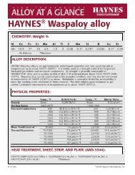
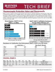
CREEP AND STRESS-RUPTURE STRENGTH<strong>HAYNES</strong> <strong>188</strong> <strong>alloy</strong> is a solidsolution-strengthenedmaterialwhich combines excellent hightemperaturestrength with goodtabricability at room temperature. It is particularly effectivefor very long-term applicationsat temperatures of 1200°F(650°C) or more. It is strongerthan nickel-base solid-solutionstrengthened<strong>alloy</strong>s, and farstronger than smple nckelchromium or iron-nicke -chromium heat-resistant <strong>alloy</strong>s.This can allow for significantsection thickness reductionwhen it is substituted for thesematerials.COMPARISON OF SHEET MATERIALS: STRESS TO PRODUCE 1% CREEP IN 1000 HOURSTEST TEMPERATURE15 750°c 800°C 850°c23010x9 625615 5600(0ft 32900°c 950°c iooo°c1009080 706050403020CtaC’)(0Ui(0100.9 I I1400°F 1500°F1600°F1700 F1800°FTEST TEMPERATURECREEP AND RUPTURE STRENGTHCOLD-ROLLED AND 2150°F (1175C) SOLUTION-ANNEALED SHEETTestApproximate Initial Stress, Ksi (MPa)TemperatureCreep,to Produce Specified Creep in:°F(°C)% 10 Hrs. 100 Hrs. 1,000 Hrs.1400(760) 0.5 22.5 (155) 16.4 (115) 11.7 (81)1.0 25.5 (175) 18.5 (130) 13.3 (92)Rupture 43.0 (295) 32.0 (220) 23.0 (160)1500(815) 0.5 15.5 (105) 11.1 (77) 7.8 (54)1.0 17.6 (120) 12.6 (87) 8.8 (61)Rupture 31.0 (215) 21.7 (150) 15.0 (105)<strong>HAYNES</strong> <strong>188</strong> <strong>alloy</strong> 4
CREEP AND RUPTURE STRENGTHCOLD-ROLLED AND 2150°F (1175°C) SOLUTION-ANNEALED SHEET (continued)TestApproximate Initial Stress, Ksi (MPa)TemperatureCreep,to Produce Specified Creep in:°FrC)10 Hrs. 100 Hrs.1,000 Hrs.1600 (870) 0.5 10.7 (74) 7.5 (52) 5.0 (34)1.0 12.2 (84) 8.4 (58) 5.7 (39)Rupture 21.0 (145) 14.4 (99) 9.4 (65)1700(925) 0.5 7.3 (50) 4.9 (34) 3.1 (21)1.0 8.2 (57) 5.6 (39) 3.6 (25)Rupture 14.3 (99) 9.1 (63) 5.5 (38)1800 (980) 0.5 4.9 (34) 3.1 (21) 1.8 (12)1.0 5.6 (39) 3.6 (25) 2.1 (14)Rupture 9.1 (63) 5.4 (37) 2.4 (17)HOT-ROLLED AND 2150°F (1175°C) SOLUTION-ANNEALED PLATETApproximate Initial Stress, Ksi (MPa)Temperature Creep, to Produce Specified Creep in:°F (°C) 10 Hrs. 100 Hrs. 1,000 Hrs. 10,000 Hrs.1300 (705) 0.5 42.0 (289) 28.0 (193) 18.0 (124) —1.0 48.0 (339) 32.5 (224) 22.0 (152) —Rupture 76.0 (524)* 56.0 (386) 40.0 (276) 28.0 (193)*1400(760) 0.5 26.0 (179) 17.0 (117) 11.5 (79) —1.0 29.0 (200) 20.5 (141) 14.0 (97) —Rupture 52.0 (359) 37.0 (255) 26.0 (179) 18.5 (128)1500(815) 0.5 17.0 (117) 11.0 (76) 7.4 (51) —1.0 19.0 (131) 13.5 (93) 9.3 (64) —Rupture 36.0 (248) 25.0 (172) 17.5 (121) 12.0 (83)1600 (870) 0.5 11.5 (79) 7.5 (52) 5.0 (34)1.0 13.0 (90) 9.0 (62) 6.4 (44)Rupture 25.0 (172) 17.0 (117) 11.6 (80) 7.8 (54)*1700(925) 0.5 8.0 (56) 5.2 (30) 3.4 (23) —1.0 9.2 (63) 6.0 (41) 4.0 (28) —Rupture 16.5 (114) 11.1 (77) 7.3 (50) —1800 (980) 0.51.0Rupture•S gniticant extrapolation.5.66.311.5(39)(43)(79)3.6 (25)3.9 (27)7.0 (48)2.3 (16)2.9 (20)4.3 (30)<strong>HAYNES</strong> <strong>188</strong> <strong>alloy</strong>
TYPICAL TENSILE PROPERTIESCOLD-ROLLED AND 2150°F (1175°C) SOLUTION-ANNEALED SHEETUltimateTest Tensile 0.2% Yield ElongationTemperature Strength Strength in 2 in. (51 mm)°F (°C) Ksi MPa Ksi MPaRoom 137.2 945 67.3 465 531000(540) 108.5 750 42.0 290 611200 (650) 103.3 710 39.7 275 591400(760) 89.9 620 38.9 270 631600 (870) 60.0 415 35.9 250 641800 (980) 35.2 245 19.0 130 592000 (1095) 18.7 130 93 64 32HOT-ROLLED AND 2150°F (1175°C) SOLUTION-ANNEALED PLATE*TestTemperature°F (°C)Room1000(540)1200(650)1400 (760)1600 (870)1800 (980)2000(1095)2100 (1150)2200(1205)* mited data.UltimateTensileStrengthKsi MPa142.6 985112.6 775109.8 75594.0 65065.3 45038.7 26521.0 14513.9 9612.0 830.2% YieldStrengthKsi MPa68.5 47039.9 27538.3 26538.9 27036.1 25027.1 18512.8 886.9 484.0 28Elongationin 2 in. (51 mm)%566973707784896071IMPACT STRENGTH PROPERTIES*TestTemperature°F (°C)Ft-lbs.Typical Charpy V-NotchImpact ResistanceJoules-300 (-185) 116 158-150 (-100) 131 17870(20) 143 1941000(540) 117 1591300 (705) 107 145*Avemge of longitudinal and transverse tests on solution-annealed plate<strong>HAYNES</strong> <strong>188</strong> <strong>alloy</strong>
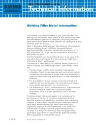
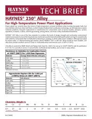
THERMAL STABILITY<strong>HAYNES</strong><strong>®</strong> <strong>188</strong> <strong>alloy</strong> is similar tothe solid-solution-strengthenedsuper<strong>alloy</strong>s, such as <strong>alloy</strong> 625or HASTELLOY<strong>®</strong> X <strong>alloy</strong>, whichwill precipitate deleteriousphases upon such long termexposure. In this case, thephase in question is a C02Wlaves phase, which serves toimpair both tensile ductility andimpact strength. The behaviorof <strong>188</strong> <strong>alloy</strong> is significantly better in this regard than <strong>HAYNES</strong>25 <strong>alloy</strong>, which it replaced; butfor applications where thermalstability is important, 230° <strong>alloy</strong>is recommended.EXPOSURE TEMPERATURE (°C)AT 500 600 700 800 900 1000I I I I I I2 ~ . Retained Room-TemperatureTensile Ductility after 8000zHour Exposure at Temperature9uJ5f3Ui-jE5zUi40 -~D200-2LiiI- 1020RT 1000 1200 1400 1600 1800ExPOSURE TEMPERATURE (°F)ROOM-TEMPERATURE PROPERTIES OF PLATE AFTER THERMAL EXPOSUREUltimateExposureTensile0.2% Yield Elongation ImpactTemperatureStrengthStrength in 2 in. (51 mm) Strength°F (°C)Hours Ksi MPa Ksi MPa % Ft-lbs. Joules1200 0 140.0 965 65.0 450 56.0 143 194(650C) 8000 151.6 1045 79.7 550 29.1 23 311400 0 140.0 965 65.0 450 56.0 143 194(7600) 8000 147.9 1020 74.0 510 10.8 3 41600 0* 146.0 1005 70.1 485 50.4 143 194(8700) 1000 157.5 1085 70.7 490 28.7 10 134000 156.0 1075 68.8 475 26.6 10 138000* 147.4 1015 64.5 445 22.2 9 1216000 146.1 1005 63.8 440 24.0 8 11Average of two test exposures. All others single exposures.COMPARATIVE IMPACTSENOTH AFTER 8000-HOUR EXPOSURESSolution-AnnealedCharpy V-Notch ImpactCharpy V-Notch Impact Following ExposureFor 8000 Hours at Temperatures, Ft-lbs. (Joules)Material Ft.-lbs. (Joules) 1200°F (650°C) 1400°F (760°C) 1600°F (870°C)230<strong>®</strong> <strong>alloy</strong> 54 (73) 30 (41) 21 (28) 21 (28)<strong>188</strong> a byXalIoy 54 (73) 15 (20) 8 (11) 15 (20)625 <strong>alloy</strong> 81 (110) 5 (7) 5 (7) 15 (2’)7 <strong>HAYNES</strong> <strong>188</strong> aloy
TYPICAL PHYSICAL PROPERTIESTemp., °F British Units Temp., °C Metric UnitsDensity Room 0.324 Ibm Room 8.98 9/cmMelting Range 2400-2570 1315-1410Electric Room 39.6 microhm-in. Room 101.0 mcrohm-cmResistivity 200 40.3 microhm-in. 100 103.0 mcrohm-cm400 41.5 microhm-in. 200 105.0 mcrohm-cm600 42.7 microhm-in. 300 107.7 microhm-cm800 43.8 microhm-in. 400 110.5 microhm-cm1000 44.7 microhm-jn. 500 112.7 microhm-cm1200 45.6 microhm-in. 600 114.8 microhm-cm1400 46.1 microhm-in. 700 116.4 microhm-crn1600 46.5 microhm-in. 800 117.5 microhm-cm1800 46.7 microhm-in. 900 118.3 microhm-cm2000 46.8 microhm-in. 1000 119.1 microhm-cmThermal Diffusivity Room 4.5 x 10~ mY/sec. Room 29.2 x 10~ cm7sec.200 5.0 x 10~ in.2/sec. 100 32.7 x 10~ cm2/sec.400 5.6 x 10~ in.2/sec. 200 36.5 x 10~ cm2/sec.600 6.Ox 10~ in.2/sec. 300 38.7x10~ cm2/sec800 6.4 x 10~ nY/sec. 400 40.8 x 10~ cm2/sec.1000 6.7 x 10 n.2/sec. 500 43.5 x 10~ cm2/sec.1200 7.1 x 10 in.2/sec 600 45.7 x 10~ cm2/sec.1400 7.6 x 10 in.2/sec. 700 48.2 x 10~ cm2/sec.1600 7.6 x 10 nY/sec. 800 50.4 x 10~ cm2/sec.1800 8.0 x 10 in.2/sec. 900 50.4 x 10~ cm2/sec.2000 8.4 x 10 n.2/sec. 1000 53.0 x 10~ cm2/sec.Thermal Conductivity Room 72 Btu-in./ft.2 hr.-°F Room 10.4 W/m-K200 84 Btu-in./tt.2 hr.-°F 100 12.2 W/m-K400 100 Btu-in./ft.2 hr.-°F 200 14.3 W/m-K600 112 Btu-in./ft.2 hr-i’ 300 15.9 W/m-K800 125 Btu-mn./ft.2 hr.-°F 400 17.5 W/m-K1000 138 Btu-in./ft.2 hr.-°F 500 19.3 W/m-K1200 152 Btu-in./ftYhr.-°F 600 21.1 W/m-K1400 167 Btu-in./tt.2 hr.-°F 700 23.0 W/m-K1600 174 Btu-in./tt.2 hr-i’ 800 24.8 W/m-K1800 189 Btu-mn./ftY hr.-°F 900 25.5 W/m-K_______________ 2000 204 Btu-in./ft.2 hr-i’ 1000 27.6 W/m-K<strong>HAYNES</strong> <strong>188</strong> <strong>alloy</strong>
Temp., °F British Units Temp., °C Metric UnitsSpecific Heat Room 0.096 BTU/lb.-°F Room 12.1 J/Kg-K200 0.101 BTU/lb.-°F 100 423 J/Kg-K400 0.106 BTU/lb.-°F 200 444 J/Kg-K600 0.112 BTU/lb.-°F 300 465 J/Kg-K800 0.117 BTU/lb.-°F 400 486 J/Kg-K1000 0.122 BTU/lb.-°F 500 502 J/Kg-K1200 0.127 BTU/lb.-°F 600 523 J/Kg-K1400 0.131 BTU/lb.-°F 700 540 J/Kg-K1600 0.136 BTU/lb.-°F 800 557 J/Kg-K1800 0.140 BTU/lb.-°F 900 573 J/Kg-K2000 0.145 BTU/lb.-°F 1000 590 J/Kg-KMean Coefficient ofThermal Expansion70-200 6.7 microinches/in-°F 25-100 12.1 μm/m-°C70-400 7.1 microinches/in-°F 25-200 12.7 μm/m-°C70-600 7.3 microinches/in-°F 25-300 13.1 μm/m-°C70-800 7.6 microinches/in-°F 25-400 13.5 μm/m-°C70-1000 7.7 microinches/in-°F 25-500 13.9 μm/m-°C70-1200 8.2 microinches/in-°F 25-600 14.3 μm/m-°C70-1400 8.5 microinches/in-°F 25-700 15.0 μm/m-°C70-1600 8.8 microinches/in-°F 25-800 15.5 μm/m-°C70-1800 9.1 microinches/in-°F 25-900 16.0 μm/m-°C25-1000 16.5 μm/m-°CTemp., °FDynamicModulus ofElasticity,10 6 psi Temp., °CDynamicModulus ofElasticity,GPaRoom 33.6 Room 232200 32.8 100 225400 31.5 200 217600 30.2 300 209800 28.9 400 2011000 27.6 500 1931200 26.2 600 1841400 24.9 700 1761600 23.6 800 1691800 22.3 900 1612000 21.0 1000 1539
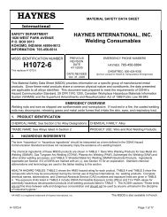
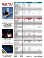
LOW CYCLE FATIGUE PROPERTIES<strong>HAYNES</strong><strong>®</strong> <strong>188</strong> <strong>alloy</strong> exhibits for strain-controlled tests run machined from bar. Tests werevery good low cycle fatigue in the temperature range from run with fully reversed strainproperties at elevated tempera- 800°F (425°C) to 1600°F (R = -1) at a frequency oftures. Results shown below are (870°C). Samples were 20 cpm (0.33 Hz).2.52.0 -*wCDzzI(1)1.5 -1.00.90.80.70.60.5 -0.4 -x800°F (425°C)j*~discontinued0.3 -tl6000F (870°c)02I1 o3I10~CYCLES TO FAILURE10° 10~COMPARATIVE LOW CYCLE FATIGUE PROPERTIESThe graph below compares (760°C)/1 000 hour pre- again run with fully reversedthe low cycle fatigue lives of a exposed condition. Samples strain (R — 1) at a frequency ofnumber of <strong>alloy</strong>s tested at were machined from plate or 20 cpm (0.33 Hz). TSR = Total800°F (425°C) in both the bar, after exposure for ex- Strain Range.as-received and 1400°Fposed samples. Tests were800°F (425°C) LCF Life for Various Alloys1 60TSR= 10%~50.5 .5woDLiir 40DTSR=065%—30oI—(1) s U)w tu 20-3o 010 —0 0<strong>188</strong> 230 X 625 617 <strong>188</strong> 230 X 625 617C As Received1400°F (760°C)/1000 Hr prior exposure<strong>HAYNES</strong> <strong>188</strong> <strong>alloy</strong> 10
OXIDATION RESISTANCE<strong>HAYNES</strong><strong>®</strong> <strong>188</strong> <strong>alloy</strong> exhibits environments, and can be used sures of short duration, <strong>188</strong>very good resistance to both air for long-term continuous expo- <strong>alloy</strong> can be used at higherand combustion gas oxidizing sure at temperatures up to temperatures.2000°F (1095°C). For expoCOMPARATIVE BURNER RIG OXiDATION RESISTANCE1000 HOUR EXPOSURE AT 1100°F (980°C)MetalLossAverageMetal AffectedMaximumMetal AffectedMaterial Mils pamMils pamMils pam230<strong>®</strong> <strong>alloy</strong> 0.8 20 2.8 71 3.5 89<strong>HAYNES</strong><strong>®</strong> <strong>188</strong> <strong>alloy</strong> 35 89 4.2 107HASTELLOY X <strong>alloy</strong> 2.7 69 5.6 142 6.4 153625 <strong>alloy</strong> 4.9 124 7.1 180 7.6 193617 <strong>alloy</strong> 2.7 69 9.8 249 10.7 272Oxidation Test ParametersBurner r g ox dation tests were combustion of No. 2 fuel oil from the gas stream every 30conducted by exposing sam- burned at a ratio of air to fuel of minutes and fan-cooled to nearpIes 3/8 in. x 2.5 in. x thickness about 50:1. (Gas velocity was amb ent temperature and then(9 mm x 64 mm x thickness), in about 0.3 mach). Samples reinserted into the flame tunnel.a rotating holder, to products of were automatically removedCOMPARA1HVE BURNER RIG OXIDATION RESISTANCE AT 2000°F (1095°C) FOR 500 HOURSOXDATION DAMAGE100 200 300 400 500 600 700 800 900sMMaximum230<strong>®</strong> <strong>alloy</strong> Metal Internal<strong>188</strong> <strong>alloy</strong>LossPenetrationx <strong>alloy</strong>617 <strong>alloy</strong> (>24 mils)625 <strong>alloy</strong> (>31 mils)5 10 15 20 25 30 35OXIDATION DAMAGE, MILS<strong>HAYNES</strong> <strong>188</strong> <strong>alloy</strong>
COMPARATIVE OXIDAT~ON RESISTANCE IN FLOWING A~R*Average Metal Affected in 1008 Hours”1800°F (980°C) 2000°F (1095°C) 2100°F (1150°C)Material Mils jim Mils jim Mils jim230<strong>®</strong><strong>alloy</strong> 0.7 18 1.3 33 3.4 86<strong>HAYNES</strong><strong>®</strong> <strong>188</strong> <strong>alloy</strong> 8.0 2036l7<strong>alloy</strong> 1.3 33 1.8 46 3.4 86HASTELLOY<strong>®</strong>X<strong>alloy</strong> 0.9 23 2.7 69 5.8 147625 <strong>alloy</strong> 0.7 18 4.8 122 18.2 462Flowing air at a velocity of 7.0 ftimin. (213.4 cnvmin.) past the samples. samples cycled to room temperature once-a-week.• * Metal Loss + Average Internal Penetration.HOT CORROSION RESISTANCE AT 1650°F (900°C)<strong>HAYNES</strong> <strong>188</strong> <strong>alloy</strong> exhibits No. 2 Fuel oil with 0.4 percent cycled out of the gas streamexcellent resistance to sulfate sulfur. The air:fuel ratio was once-an-hour and cooled todeposit type hot corrosion. 30:1. Artificial sea water was near ambient temperature. GasTests were conducted in a low injected at a rate equivalent to velocity was 13 ft/sec. (4 mIs).velocity burner rig burning5 ppm salt. Tests were run for1000 hours, with samplesMetal LossAverage Metal AffectedMaterial Mils j.tm Mils jim<strong>HAYNES</strong> <strong>188</strong> <strong>alloy</strong> 0.8 2023O<strong>alloy</strong> 1.2 30 5.1 130625 <strong>alloy</strong> 1.8 46 5.2 132HASTELLOYXaIIoy 1.6 41 5.5 140SULFIDATION RESISTANCE AT 1400°F (760°C)________<strong>HAYNES</strong> <strong>188</strong> al oy has very a gas mixture consisting of a severe test, with equilibriumgood resistance to gaseous 5 percent H2, 5 percent CO, su fur partial pressure of 106 tosulfidation envronments 1 percent CO , 0.15 percent 10 and oxygen partia presencountered in various indus- H2S and 0.1 percent H 0, bal- sures less than that needed totrial applications. Tests were ance Ar. Coupons were produce protective chromiumconducted at 1400°F (760°C) in exposed for 215 hours. This is oxide scales.1614°~o 120~~~ot=108642400300200 r100<strong>188</strong> 556 310 617 800H 625 x<strong>HAYNES</strong> <strong>188</strong> a oy 12
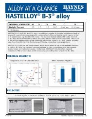
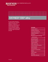
SCHEMATIC REPRESENTATION OF METALLOGRAPHJC TECHNIOUEUSED FOR EVALUATING ENVIRONMENTAL TESTSj Iv~rt:n.-0:‘E.~r1. Metal Loss = (A - 8)122. Average Internal Penetration = C3. Maximum Internal Penetration = D4. Average Metal Affected = ((A - 8)12) + C5. Maximum Metal Affected = ((A - 8)12) + DFABRICATION CHARACTERISTICSHEAT TREATMENT<strong>HAYNES</strong> <strong>188</strong> <strong>alloy</strong> is normallyfinal so ution heat-treated at2150°F (1175 C)for a timecommensurate with sectionthickness. Annealing duringtabricat on can be performed ateven lower temperatures, but afinal, subsequent solution heattreatment is needed to produceoptimum properties and structure. Please call <strong>Haynes</strong><strong>International</strong> for further nformaton.EFFECT OF COLD REDUCT~ON UPON ROOM-TEMPERATURE PROPERTIES*%ColdReductionSubsequentTemperatureUltimateTensileStrength0.2% YieldStrengthElongationin 2 in. (51 mm)Ksi MPa Ksi MPa % Hardness0 137.2 945 66.9 460 54.2 RB 98.110 151.5 1045 105.9 730 45.1 R~32.120 None 165.9 1145 132.9 915 28.3 R~37.130 195.1 1345 167.0 1150 13.4 R~41.240 214.9 1480 176.8 1220 9.8 R~43.510 148.5 1025 91.2 630 41.4 R~29.720 1950°F 153.3 1055 87.8 605 41.0 R~27.830 158.3 1090 84.2 580 41.3 R~29.640 162.7 1120 90.8 625 39.8 R~31.110 143.0 985 64.7 445 50.1 R~21.920 2050°F 149.0 1025 71.4 490 47.2 R~24.511120°C~30 br s mir~ 155.2 1070 80.3 555 43.7 Ac 27.640 159.0 1095 86.9 600 43.2 Ac 29.510 139,6 965 61.9 425 55.3 RB95.620 2150°F 141.3 975 64.9 445 53.3 A9 97.130 142.8 985 66.5 460 51.8 RB 98.540 141.5 975 64.1 440 55.5 RB 97.2* Based upon rolling reduction taken upon 0.125 in. (3.2 mm) thick sheet. Duplicate tests.13 <strong>HAYNES</strong> <strong>188</strong> <strong>alloy</strong>
WELDING<strong>HAYNES</strong> <strong>188</strong> <strong>alloy</strong> is readi ywelded by Gas Tungsten Arc(TIG), Gas Metal Arc (MIG),Shie ded Metal Arc (coatedelectrodes), electron beamwelding and resistance weldingtechniques. Its welding characteristics are similar to those for<strong>HAYNES</strong> 25 <strong>alloy</strong>. SubmergedArc welding is not recommended as this process ischaracterized by high heatinput to the base metal andslow cooIng of the weld. Thesefactors can ncrease weldrestraint and promote cracking.Base Metal PreparationThe joint surface and adjacentarea should be thoroughlycleaned before welding. Allgrease, oil, crayon marks, sulfur compounds and otherforeign matter should beremoved. Contact with copperor copper-bearing materials inthe joint area should beavoided. It is preferable, butnot necessary, that the <strong>alloy</strong> bein the solution-annealed condition when welded.Filler Metal SelectionMatching composition fillermetal is recommended for joining <strong>188</strong> <strong>alloy</strong>. For joiningsection thicknesses greaterthan 3/8 in. (9.5 mm) 230~Wwfiller wire is suggested. Forshielded metal arc welding,<strong>HAYNES</strong> 25 <strong>alloy</strong> electrodes(AMS 5796) are suggested. Fordissimilar metal joining of <strong>188</strong><strong>alloy</strong> to nickel-, cobalt- or ironbasematerials, <strong>188</strong> <strong>alloy</strong> itself,230-W filler wire, 556TM <strong>alloy</strong>,HASTELLOY S <strong>alloy</strong> (AMS5838) or HASTELLOY W <strong>alloy</strong>(AMS 5786, 5787) weldingproducts are suggested,depending upon the particularcase.Preheating, InterpassTemperatures and Post-WeldHeat TreatmentPreheat is not usually requiredso ong as base meta to bewelded is above 32 F (0°C).Interpass temperatures generally should be low. Auxiliarycooling methods may be usedbetween weld passes, asneeded, prov d ng that suchmethods do not introduce contaminants. Post-weld heattreatment is not normal yrequired for <strong>188</strong> <strong>alloy</strong>. For further information, please contact<strong>Haynes</strong> <strong>International</strong>.HEALTH AND SAFETY INERMATIONWelding can be a safe occupation. Those in the weldingindustry, however, should beaware of the potential hazardsassociated with welding fumes,gases, radiation, electricshock, heat, eye injuries, burns,etc. Also, local, municipal,state, and federal regulations(such as those issued byOSHA) relative to weldng andcutting processes should beconsidered.Nickel-, cobalt-, and iron-base<strong>alloy</strong> products may contain, invarying concentrations, the following elemental constituents:auminum, cobalt, chromium,copper, iron, manganese,molybdenum, nickel and tungsten For specificconcentrations of these andother elements present, refer tothe Materal Safety Data Sheets(MSDS) H3095 and H1072 forthe product.Inha ation of metal dust orfumes generated from weldng,cutting, grind ng, melting, ordross handling of these <strong>alloy</strong>smay cause adverse healtheffects such as reduced lungfunction, nasal and mucousmembrane irritation. Exposureto dust or fumes which may begenerated in working withthese <strong>alloy</strong>s may alsocause eye irritation, skin rashand effects on other organsystems.The operation and maintenance of welding and cuttingequipment should conform tothe provisions of AmericanNat onal Standard ANSI/AWSZ491, (Safely in Welding andCuffing”) Attention s especia y cal ed to Section 7(Protect on of Personnel) and 8(Heath Protect on andVentilat on) of ANSI/AWS Z491.Mechanical ventilation s advisable and, under certainconditions such as a very confined space, is necessaryduring welding or cuffing operations, or both, to preventpossible exposure to hazardous fumes, gases, or dustthat may occur.<strong>HAYNES</strong> <strong>188</strong> <strong>alloy</strong>
MACH NINGOperation High Speed Steel Tools Carbide ToolsNormal Roughing M-40 series, M-2, M-33, T-4, C-i or C 2 grade square insert,(Turning/Facing) T-8 and T-15. 45 SCEA, -5 Back Rake,450 SCEA’, 0° Back Rake, -5° Side Rake,+10° Side Rake, 1/16 in. Nose Radius.1/16 in. Nose Radius. 1/4 in. depth of cut max.,1/4 in. depth of cut max., .020 feed max., 60-80 sfm0.020 feed max., depending on rigidity of setup25 sfm cutting speed. Dry3, oil4, or water-base coo ant.Water base coolant.F nish ng M-40 series, M-33, M-3, T-8 0-2 or 0-3 grade square insert,(Turning/Facing) and T-15. if possible.15-45° SCEA, +10° Back Rake, 15-45° SCEA, +5° Side Rake,+15~ Side Rake, +5 Back Rake,1/32-1/16 in. Nose Radius. 1/32-1/16 in. Nose Rad us.0.040-0.010 in. depth of cut, 0.040-0.010 in. depth of cut,Water-base coolant.DrillingM-33, M-40 series, or T-15.Peed 0.001 in/Rev. 1/16 in. dia.0.002 in./Rev. 1/4 in. dia.0.003 in/Rev. 1/2 in. da.0.004 in/Rev. 1 in. d a.Speed 10-20 sfm.Oil or water-base coolant.Use coolant feed drills if p055 ble.Use short drills, heavy web135° crankshaft grind pointswherever possible.NOTES: 1 SCEA — side cutting edge angle or lead angle of the tool.Dry or water-base coolant.C-2 grade not recommended,but solid or tipped dr Is maybe successful on rigid setups.The web must be thinned toreduce thrust.Use 135° included angle on point.30-60 sfm.Coolant-feed carbide tippeddrills can be economical insome setups.Q~ - or water-base coolant.2 Water-base coolant should be premium quality, sulfochiorinated water soluble oil or chemical emulsion with extreme pressure additives. Dilute with water tomake 15:1 mix.3 At any point where dry cutting is recommended, an air let directed on the tool may provide substantial tool life increases. A water-base coolant mist mayalso be effective.4 Oil coolant should be a premium quality, sulfochiorinated oil with extreme pressure additives. A viscosity at 1 006F from 50 to 125 ssu5 Water4ase coolant may cause chipping and rapid failure of carbide tools in interrupted cuts.6 Negative rake tools should be used for interrupted cuts.<strong>HAYNES</strong> <strong>188</strong> <strong>alloy</strong>
STANDARD PRODUCTSBy Brand or Alloy Designation:HASTELLOY <strong>®</strong> Corrosion-Resistant AlloysB-3 <strong>®</strong> , C-4, C-22 <strong>®</strong> , C-22HS <strong>®</strong> , C-276, C-2000 <strong>®</strong> , G-30 <strong>®</strong> , G-35 <strong>®</strong> , G-50 <strong>®</strong> , HYBRID-BC1, and NHASTELLOY <strong>®</strong> High-Temperature AlloysS, W, and X<strong>HAYNES</strong> <strong>®</strong> High-Temperature Alloys25, R-41, 75, HR-120 <strong>®</strong> , HR-160 <strong>®</strong> , HR-224, <strong>188</strong>, 214 <strong>®</strong> , 230 <strong>®</strong> , 230-W <strong>®</strong> , 242 <strong>®</strong> , 263, 282 <strong>®</strong> , 556 <strong>®</strong> , 617, 625,625SQ <strong>®</strong> , 718, X-750, MULTIMET <strong>®</strong> , NS-163, and WaspaloyCorrosion-Wear Resistant AlloyULTIMET <strong>®</strong><strong>HAYNES</strong> <strong>®</strong> Titanium Alloy TubularTi-3Al-2.5VWear-Resistant Alloy6BStandard Forms: Bar, Billet, Plate, Sheet, Strip, Coils, Seamless or Welded Pipe & Tubing, PipeFittings, Flanges, Fittings, Welding Wire, and Coated ElectrodesProperties Data: The data and information in this publication arebased on work conducted principally by <strong>Haynes</strong> <strong>International</strong>,<strong>Inc</strong>. and occasionally supplemented by information from the openliterature, and are believed to be reliable. However, <strong>Haynes</strong>does not make any warranty or assume any legal liability orresponsibility for its accuracy, completeness, or usefulness,nor does <strong>Haynes</strong> represent that its use would not infringeupon private rights.Any suggestions as to uses and applications for specific<strong>alloy</strong>s are opinions only and <strong>Haynes</strong> <strong>International</strong>, <strong>Inc</strong>. makes nowarranty of results to be obtained in any particular situation. Forspecific concentrations of elements present in a particular productand a discussion of the potential health affects thereof, refer tothe Material Safety Data Sheet supplied by <strong>Haynes</strong> <strong>International</strong>,<strong>Inc</strong>. All trademarks are owned by <strong>Haynes</strong> <strong>International</strong>, <strong>Inc</strong>.052008Global Headquarters1020 West Park AvenueP.O. Box 9013Kokomo, Indiana 46904-9013 (USA)Phone: 1-800-354-0806 or (765) 456-6012Fax: (765) 456-6905www.haynesintl.comFor your local service center or sales offi ce, please call or visit our website.