ESR-2606 - Simpson Strong-Tie Company, Inc. - ladbs
ESR-2606 - Simpson Strong-Tie Company, Inc. - ladbs
ESR-2606 - Simpson Strong-Tie Company, Inc. - ladbs
- No tags were found...

Create successful ePaper yourself
Turn your PDF publications into a flip-book with our unique Google optimized e-Paper software.
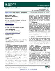
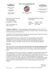
Page 5 of 9<strong>ESR</strong>-<strong>2606</strong>TABLE 2—ALLOWABLE LOADS FOR A34 AND A35 FRAMING CONNECTORSFASTENERS (Quantity-Type) ALLOWABLE LOADS 3,4,5 (lbs)MODEL NO.CONNECTION LOADC D = 1.25Joist Header/Plate CONFIGURATION 1 DIRECTION 2 C D = 1.0 C D = 1.15 C D = 1.33A34 4-8dx1½ 4-8dx1½C D = 1.6See A34 FramingF 1 345 365 365Illustration(6)F 2 280 280 280A 1 260 295 3203-8dx1½ 6-8dx1½ 2E 260 295 320C 1 170 170 170A35A 2 260 295 3206-8dx1½ 6-8dx1½ 3C 2 260 295 315D 150 150 1506-8dx1½ 6-8dx1½ 4F 1 450 450 450(6)F 2 515 595 645For SI: 1 inch = 25.4 mm, 1 lbs = 4.45 N.1. Some illustrations show connections that could cause cross-grain tension or bending of the wood during loading if not reinforced sufficiently.In this case, mechanical reinforcement should be considered.2. Refer to the illustrations in Figure 2 for definitions of load directions (A 1, A 2, C 1, C 2, D, E, F 1, F 2).3. Tabulated allowable loads must be selected based on duration of load as permitted by the applicable building code.4. Allowable loads are for one anchor. When anchors are installed on each side of the joist, the minimum joist thickness is 3 inches.5. Allowable loads under C D = 1.33 or 1.6 column have been increased for wind or earthquake loading. No further increase is allowed.Allowable loads must be reduced when other load durations govern.6. Connectors are required on both sides of joist to achieve F 2 loads in both directions.A34 Framing Connection3 A352 A35A35 Framing Connections4 A35FIGURE 2—A34 AND A35 FRAMING CONNECTORS