ESR-2606 - Simpson Strong-Tie Company, Inc. - ladbs
ESR-2606 - Simpson Strong-Tie Company, Inc. - ladbs
ESR-2606 - Simpson Strong-Tie Company, Inc. - ladbs
- No tags were found...

Create successful ePaper yourself
Turn your PDF publications into a flip-book with our unique Google optimized e-Paper software.
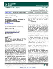
<strong>ESR</strong>-<strong>2606</strong>Issued February 1, 2008This report is subject to re-examination in two years.ICC Evaluation Service, <strong>Inc</strong>.www.icc-es.orgBusiness/Regional Office # 5360 Workman Mill Road, Whittier, California 90601 # (562) 699-0543Regional Office # 900 Montclair Road, Suite A, Birmingham, Alabama 35213 # (205) 599-9800Regional Office # 4051 West Flossmoor Road, Country Club Hills, Illinois 60478 # (708) 799-2305DIVISION: 06—WOOD AND PLASTICSSection: 06090—Wood and Plastics FasteningsREPORT HOLDER:SIMPSON STRONG-TIE COMPANY, INC.5956 WEST LAS POSITAS BOULEVARDPLEASANTON, CALIFORNIA 94588(800) 925-5099www.strongtie.comEVALUATION SUBJECT:SIMPSON STRONG-TIE STRUCTURAL ANGLES, CLIPS,AND PLATES FOR WOOD FRAMING1.0 EVALUATION SCOPECompliance with the following codes:# 2006 International Building Code ® (IBC)# 2006 International Residential Code ® (IRC)# Other Codes (see Section 8.0)Properties evaluated:Structural2.0 USESThe <strong>Simpson</strong> <strong>Strong</strong>-<strong>Tie</strong> structural angles, clips, and platesdescribed in this report are used as wood-to-wood connectorsin accordance with Section 2304.9.3 of the IBC. The angles,clips, and plates may also be used in structures regulatedunder the IRC when an engineered design is submitted inaccordance with Section R301.1.3 of the IRC.3.0 DESCRIPTION3.1 General:The angles, clips, and plates described in this report are usedas wood-to-wood connections in structural systems that havebeen designed to transfer loads from their point of origin toload-resisting elements.3.1.1 A Series Angles:The A series angles are formed from No. 18 gage galvanizedsteel. See Table 1 for angle model numbers, angledimensions, fastener schedules, and allowable loads. SeeFigure 1 for a drawing of A series angles connecting a woodpost to a wood sill plate.3.1.2 A34 and A35 Framing Angles:The A34 and A35 framing angles are formed from No. 18gage galvanized steel. The A35 angle has slots and bendlines to permit field adjustments of the legs for two- and threewaytied connections. The A34 is an equal leg angle withoutslots or bend lines. See Table 2 for angle dimensions,fastener schedules, and allowable loads. See Figure 2 forillustrations of framing configurations with the A34 and A35angles.3.1.3 LTP4 Lateral <strong>Tie</strong> Plate:The LTP4 lateral tie plate is formed from No. 20 gagegalvanized steel. See Table 3 for fastener schedules andallowable loads. See Figure 3 for dimensions of the LTP4connector and a drawing of the LTP4 used as a top plate-torimjoist connections.3.1.4 FC Series Framing Clips:The FC series framing clips are formed from No. 16 gagegalvanized steel. See Table 4 for clip model numbers, clipdimensions, fastener schedules, and allowable loads. SeeFigure 4 for clip dimensions and a drawing of FC framing clipsused as an alternative to cripple studs for headers and usedto connect a wood post to a wood sill plate.3.1.5 HH Series Header Hangers:The HH series header hangers are formed from No. 16 gagegalvanized steel. See Table 5 for hanger model numbers,hanger dimensions, fastener schedules, and allowable loads.See Figure 5 for hanger dimensions and a drawing of an HHhanger connecting a wood door header to jambs.3.1.6 GA Series Gusset Angles:The GA series gusset angles are formed from No. 18 gagegalvanized steel. See Table 6 for gusset angle modelnumbers, angle length, fastener schedules, and allowableloads. See Figure 6 for a drawing of a GA angle connectinga joist to a header.3.1.7 L Series Reinforcing Angles:The L series reinforcing angles are formed from No. 16 gagegalvanized steel. See Table 7 for angle model numbers,angle length, fastener schedules, and allowable loads. SeeFigure 7 for angle dimensions and a drawing of an L angleconnecting a joist to a header.3.1.8 LS Series Skewable Angles:The LS series skewable angles are formed from No. 18 gagegalvanized steel. The angle is fabricated to assist fieldadjustment from zero degrees up to a 135-degree bend. SeeTable 8 for angle model numbers, angle length, fastenerschedules, and allowable loads. See Figure 8 for angledimensions and a drawing of an LS angle connecting askewed joist to a header.3.1.9 Z Series Panel Stiffener Clips:The Z series stiffener clips are formed from No. 12 gagegalvanized steel. The Z clips are used to support nominally 2-by-4 or 2-by-6 wood blocking between joists or trusses thatprovide solid backing for ceiling panel material. See Table 9are not to be construed as representing aesthetics or any other attributes not specifically addressed, nor are they to be construed as anendorsement of the subject of the report or a recommendation for its use. There is no warranty by ICC Evaluation Service, <strong>Inc</strong>., express or implied, as to anyfinding or other matter in this report, or as to any product covered by the report.Copyright © 2007 Page 1 of 9
Page 2 of 9 <strong>ESR</strong>-<strong>2606</strong>for Z clip model numbers, clip dimensions, fastenerschedules, and allowable loads. See Figure 9 for Z clipdimensions and an illustration of Z clips supporting woodblocking for ceiling panels.3.2 Materials:3.2.1 Steel: The angles, clips, and plates described in thisreport are manufactured from galvanized steel in accordancewith ASTM A 653, SS designation, Grade 33, with a minimumyield strength, F y , of 33,000 psi (227 MPa) and a minimumtensile strength, F u , of 45,000 psi (310 MPa). Base-metalthicknesses for the connectors in this report are as follows:NOMINAL THICKNESS(inches0MINIMUM BASE-METALTHICKNESS (inch)No. 12 0.0975No. 16 0.0555No. 18 0.0445No. 20 0.0335For SI: 1 inch = 25.4 mm.The connectors have a minimum G90 zinc coatingspecification in accordance with ASTM A 653. Some models(designated with a model number ending with Z) are availablewith a G185 zinc coating specification in accordance withASTM A 653. Some models (designated with a model numberending with HDG) are available with a hot-dip galvanization,also known as “batch” galvanization, in accordance withASTM A 123, with a minimum specified coating weight of 2.0ounces of zinc per square foot of surface area (600 g/m 2 ),total for both sides. Model numbers in this report do notinclude the Z or HDG ending, but the information shownapplies. The lumber treater or holder of this report (<strong>Simpson</strong><strong>Strong</strong>-<strong>Tie</strong> <strong>Company</strong>) should be contacted forrecommendations on minimum corrosion resistance of steelconnectors in contact with the specific proprietarypreservative treated or fire retardant treated lumber.3.2.2 Wood: Wood members which the connectors areused must be either sawn lumber or engineered lumberhaving a minimum specific gravity of 0.50 (minimumequivalent specific gravity of 0.50 for engineered lumber), andhaving a maximum moisture content of 19 percent (16percent for engineered lumber) except as noted in Section4.1. The thickness of the wood main member must be equalto or greater than the length of the fasteners specified in thetables in this report, or as required by wood member design,whichever is greater.3.2.3 Fasteners: Nails used for connectors described in thisreport must comply with ASTM F 1667 and have the followingminimum fastener dimensions and bending yield strengths(F yb ):COMMONNAILSHANKDIAMETER(inch)NAIL LENGTH(inches)F yb(psi)8d × 1 1 / 2 0.131 1 1 / 2 100,00010d × 1 1 / 2 0.148 1 1 / 2 90,00010d 0.148 3 90,00016d 0.162 3 1 / 2 90,000For SI: 1 inch = 25.4 mm, 1 psi = 6.895 kPa.Fasteners used in contact with preservative treated or fireretardant treated lumber must comply with IBC Section2304.9.5 or IRC Section R319.3, as applicable. The lumbertreater or this report holder (<strong>Simpson</strong> <strong>Strong</strong>-<strong>Tie</strong> <strong>Company</strong>)should be contacted for recommendations on minimumcorrosion resistance of fasteners and connection capacitiesof fasteners used with the specific proprietary preservativetreated or fire retardant treated lumber.4.0 DESIGN AND INSTALLATION4.1 Design:The tabulated allowable loads shown in this report are basedon allowable stress design (ASD) and include the loadduration factor, C D , corresponding with the applicable loadsin accordance with the NDS.Tabulated allowable loads apply to products connected towood used under dry conditions and where sustainedtemperatures are 100ºF (37.8ºC) or less. When products areinstalled to wood having a moisture content greater than 19percent (16 percent for engineered wood products), or wherewet service is expected, the allowable loads must be adjustedby the wet service factor, C M , specified in the NDS. Whenconnectors are installed in wood that will experiencesustained exposure to temperatures exceeding 100ºF(37.8ºC), the allowable loads in this report must be adjustedby the temperature factor, C t , specified in the NDS.Connected wood members must be analyzed for loadcarryingcapacity at the connection in accordance with theNDS.4.2 Installation:Installation of the connectors must be in accordance with thisevaluation report and the manufacturer’s publishedinstallation instructions. In the event of a conflict between thisreport and the manufacturer’s published installationinstructions, this report governs.4.3 Special Inspection:4.3.1 IBC: Periodic special inspection is required forinstallation of connectors described in this report that aredesignated as components of a seismic-force-resistingsystem for a structure in Seismic Design Category C, D, E orF in accordance with Section 1707.3 or 1707.4, with theexception of those structures that qualify under Section1704.1.4.3.2 IRC: Special inspections are not required.5.0 CONDITIONS OF USEThe <strong>Simpson</strong> <strong>Strong</strong>-<strong>Tie</strong> structural angles, clips, and platesdescribed in this report comply with, or are suitablealternatives to what is specified in, those codes listed inSection 1.0 of this report, subject to the following conditions:5.1 The connectors must be manufactured, identified andinstalled in accordance with this report and themanufacturer’s published installation instructions. Acopy of the instructions must be available at the jobsiteat all times during installation.5.2 Calculations showing compliance with this report mustbe submitted to the code official. The calculations mustbe prepared by a registered design professional whererequired by the statues of the jurisdiction in which theproject is to be constructed5.3 Adjustment factors noted in Section 4.1 and theapplicable codes must be considered, where applicable.5.4 Connected wood members and fasteners must comply,respectively, with Sections 3.2.2 and 3.2.3 of this report.5.5 Use of connectors with preservative treated or fireretardant treated lumber must be in accordance withSection 3.2.1 of this report. Use of fasteners withpreservative treated or fire retardant treated lumbermust be in accordance with Section 3.2.3 of this report.
Page 3 of 9 <strong>ESR</strong>-<strong>2606</strong>6.0 EVIDENCE SUBMITTEDData in accordance with the ICC-ES Acceptance Criteria forJoist Hangers and Similar Devices (AC13), dated October2006 (corrected March 2007).7.0 IDENTIFICATIONThe products described in this report are identified with a diestampedlabel indicating the name of the manufacturer(<strong>Simpson</strong> <strong>Strong</strong>-<strong>Tie</strong>), the model number, and the number ofan index evaluation report (<strong>ESR</strong>-2523) that is used as anidentifier for the products recognized in this report.8.0 OTHER CODES8.1 Evaluation Scope:In addition to the codes referenced in Section 1.0, theproducts in this report were evaluated for compliance with therequirements of the following codes:# 2003 International Building Code ® (2003 IBC)# 2003 International Residential Code ® (2003 IRC)# 2000 International Building Code ® (2000 IBC)# 2000 International Residential Code ® (2000 IRC)# 1997 Uniform Building Code (UBC)The products described in this report comply with, or aresuitable alternatives to what is specified in, the codes listedabove, subject to the provisions of Sections 8.2 through 8.7.8.2 Uses:8.2.1 2003 IBC, 2003 IRC, 2000 IBC, and 2000 IRC: SeeSection 2.0 of this report.8.2.2 UBC: Replace the information in Section 2.0 with thefollowing: <strong>Simpson</strong> <strong>Strong</strong>-<strong>Tie</strong> structural angles, clips, andplates are used as wood framing connectors in accordancewith Section 2318.4.8 of the UBC.8.3 Description:8.3.1 2003 IBC and 2003 IRC: See Section 3.0 of thisreport.8.3.2 2000 IBC and 2000 IRC: See Section 3.0 of thisreport, except modify Section 3.2.3 of this report to referenceSection R323.3 of the IRC.8.3.3 UBC: See Section 3.0 of this report, except modify thefirst sentence in the last paragraph of Section 3.2.3 asfollows: Fasteners used in contact with preservative treatedor fire retardant treated lumber must, as a minimum, complywith UBC Section 2304.3.8.4 Design and Installation:8.4.1 2003 IBC, 2003 IRC, 2000 IBC, 2000 IRC: SeeSection 4.0 of this report.8.4.2 UBC: The same as Section 4.0 of this report, exceptdelete Section 4.3 since special inspection is not required.8.5 Conditions of Use:8.5.1 2003 IBC, 2003 IRC 2000 IBC, and 2000 IRC: The<strong>Simpson</strong> <strong>Strong</strong>-<strong>Tie</strong> products described in this report complywith, or are suitable alternatives to what is specified in, thosecodes listed in Section 8.0, subject to the same conditions ofuse indicated in Section 5.0 of this report.8.5.2 UBC: The <strong>Simpson</strong> <strong>Strong</strong>-<strong>Tie</strong> products described inthis report comply with, or are suitable alternatives to what isspecified in, the UBC, subject to the same conditions of useindicated in Section 5.0 of this report, except the lastsentence of Section 5.5 is replaced with the following:Fasteners used in contact with preservative treated or fireretardant treated lumber must, as a minimum, comply withUBC Section 2304.3.8.6 Evidence Submitted: 2003 IBC, 2003 IRC 2000 IBC,2000 IRC, and UBC:See Section 6.0 of this report.8.7 Identification: 2003 IBC, 2003 IRC 2000 IBC, 2000IRC, and UBC:See Section 7.0 of this report.
Page 5 of 9<strong>ESR</strong>-<strong>2606</strong>TABLE 2—ALLOWABLE LOADS FOR A34 AND A35 FRAMING CONNECTORSFASTENERS (Quantity-Type) ALLOWABLE LOADS 3,4,5 (lbs)MODEL NO.CONNECTION LOADC D = 1.25Joist Header/Plate CONFIGURATION 1 DIRECTION 2 C D = 1.0 C D = 1.15 C D = 1.33A34 4-8dx1½ 4-8dx1½C D = 1.6See A34 FramingF 1 345 365 365Illustration(6)F 2 280 280 280A 1 260 295 3203-8dx1½ 6-8dx1½ 2E 260 295 320C 1 170 170 170A35A 2 260 295 3206-8dx1½ 6-8dx1½ 3C 2 260 295 315D 150 150 1506-8dx1½ 6-8dx1½ 4F 1 450 450 450(6)F 2 515 595 645For SI: 1 inch = 25.4 mm, 1 lbs = 4.45 N.1. Some illustrations show connections that could cause cross-grain tension or bending of the wood during loading if not reinforced sufficiently.In this case, mechanical reinforcement should be considered.2. Refer to the illustrations in Figure 2 for definitions of load directions (A 1, A 2, C 1, C 2, D, E, F 1, F 2).3. Tabulated allowable loads must be selected based on duration of load as permitted by the applicable building code.4. Allowable loads are for one anchor. When anchors are installed on each side of the joist, the minimum joist thickness is 3 inches.5. Allowable loads under C D = 1.33 or 1.6 column have been increased for wind or earthquake loading. No further increase is allowed.Allowable loads must be reduced when other load durations govern.6. Connectors are required on both sides of joist to achieve F 2 loads in both directions.A34 Framing Connection3 A352 A35A35 Framing Connections4 A35FIGURE 2—A34 AND A35 FRAMING CONNECTORS
Page 6 of 9<strong>ESR</strong>-<strong>2606</strong>MODELNO.TABLE 3—ALLOWABLE LOADS FOR THE LTP4 FRAMING CONNECTORFASTENERS (Quantity-Type)ALLOWABLE LOADS 1,2 (lbs)DIRECTIONRim JoistPlatesOF LOAD Cor BlockingD = 1.0 C D = 1.15 C D = 1.25C D = 1.33C D = 1.66-8dx1 1 / 2 6-8dx1 1 / 2 G 515 590 645 685LTP46-8dx1 1 / 2 6-8dx1 1 / 2 H 515 590 645 685For SI: 1 inch = 25.4 mm, 1 lbs = 4.45 N.1. Tabulated allowable loads must be selected based on duration of load as permitted by the applicable building code.2. The LTP4 may be installed over wood-based structural sheathing (as shown in Figure 3) having a maximum thickness of 1 / 2 inch withoutadversely affecting the tabulated allowable loads.LTP4 DimensionsLTP4 Installed overSheathingLTP4attachingTop Plates toRim JoistFIGURE 3—LTP4 FRAMING CONNECTORMODEL NO.TABLE 4—ALLOWABLE LOADS FOR THE FC FRAMING CONNECTORS 1,2,3CONNECTOR WIDTH (W)(in)FASTENERS(Quantity-Type)ALLOWABLE DOWNLOAD, F 1WhereC D=1.0C D=1.15C D=1.25(lbs.)FC4 3 9 / 16 8-16d 800FC6 5 1 / 2 10-16d 920For SI: 1 inch = 25.4 mm, 1 lbs = 4.45 N.1. Tabulated allowable loads must be selected based on duration of load as permitted by the applicable building code.2. Minimum thickness of the supporting member (post) must be 2 1 / 2 inches to achieve the table load value (similar to Figure 5).3. Loads may not be increased for short-term loading.FC Connector DimensionsTypical FC Connector InstallationFIGURE 4—FC CLIPS
Page 7 of 9<strong>ESR</strong>-<strong>2606</strong>MODELNO.HANGERDIMENSIONS 1(in)TABLE 5—ALLOWABLE LOADS FOR THE HH HEADER HANGERSFASTENERS(Quantity-Type)ALLOWABLE LOADS 2,3,4,5(lbs)F 1 where C D = F 2 where C D = F 3 where C D =W H Stud Header1.0 1.25 1.0 1.33 or 1.6 1.0 1.33 or 1.6HH4 3 9 / 16 2 7 / 8 9-16d 4-16d 1,195 1,495 530 710 530 710HH6 5 1 / 2 5 1 / 4 12-16d 6-16d 1,595 1,995 800 1,065 800 1,065For SI: 1 inch = 25.4 mm, 1 lbs = 4.45 N.1. Refer to Figure 5 for definitions of angle dimension nomenclature (W and H).2. Tabulated allowable loads must be selected based on duration of load as permitted by the applicable building code.3. Allowable F 2 and F 3 loads under C D = 1.33 or 1.6 column have been increased for wind or earthquake loading. No further increase isallowed. Allowable loads must be reduced when other load durations govern.4. Duration of load increase for F 1 direction may not exceed 25 percent.5. Minimum lumber thickness must be 2½ inches to achieve tabulated allowable load values.HH4 Hanger DimensionsTypical HH InstallationAllowable Load DirectionsFIGURE 5—HH HEADER HANGERS
Page 8 of 9<strong>ESR</strong>-<strong>2606</strong>TABLE 6—ALLOWABLE LOADS FOR THE GA ANGLESALLOWABLE LOADS 1,2,3 (lbs)ANGLEMODEL LENGTH FASTENERSF 1 where C D = F 2 where C D =NO.(L) (Quantity-Type)1.331.33(inches)1.0 1.15 1.25 or1.61.0 1.15 1.25 or1.6GA1 2 3 / 4 4-10d 185 185 185 185 220 (4) 260 (4) 280 (4) 300 (4)GA2 3 1 / 4 6-10d 335 (4) 385 (4) 415 (4) 450 (4) 335 (4) 385 (4) 420 (4) 450 (4)For SI: 1 inch = 25.4 mm, 1 lbs = 4.45 N.1. Tabulated allowable loads must be selected based on duration of load as permitted by the applicable building code.2. Allowable F 1 and F 2 loads under C D = 1.33 or 1.6 column have been increased for wind or earthquake loading. No further increase is allowed.Allowable loads must be reduced when other load durations govern.3. Connectors are required on both sides to achieve F 2 loads in both directions.4. 10dx1 1 / 2-inch-long nails may be used provided the tabulated allowable loads are multiplied by 0.81, except for the GA1 angles in the F 1 direction,which must be limited to 185 lbs for all load durations.GA1FIGURE 6—GA ANGLESTypical GA InstallationTABLE 7—ALLOWABLE LOADS FOR THE L REINFORCING ANGLESALLOWABLE LOADS 1,2,3,4 (lbs)ANGLEMODEL LENGTH FASTENERSF 1 where C D = F 2 where C D =NO.(L) (Quantity-Type)1.331.33(inches)1.0 1.15 1.25 or1.61.0 1.15 1.25 or1.6L30 3 4-10d 220 240 240 240 220 255 280 295L50 5 6-10d 335 385 415 445 335 385 415 445L70 7 8-10d 445 510 555 565 445 510 555 565L90 9 10-10d 555 640 695 740 555 640 695 740For SI: 1 inch = 25.4 mm, 1 lbs = 4.45 N.1. Tabulated allowable loads must be selected based on duration of load as permitted by the applicable building code.2. Allowable F 1 and F 2 loads under C D = 1.33 or 1.6 column have been increased for wind or earthquake loading. No further increase is allowed.Allowable loads must be reduced when other load durations govern.3. Minimum lumber thickness must be 2 1 / 2 inches to achieve the tabulated allowable load values.4. 10dx1½ nails may be used provided the tabulated allowable loads are multiplied by 0.81.5. Connectors are required on both sides to achieve F 2 loads in both directions.L AngleTypical L50 Installation and Allowable Load DirectionsFIGURE 7—L REINFORCING ANGLES
Page 9 of 9<strong>ESR</strong>-<strong>2606</strong>MODEL NO.ANGLELENGTH (in)TABLE 8—ALLOWABLE LOADS FOR THE LS REINFORCING ANGLESALLOWABLE LOAD PARALLEL TO LENGTH OF ANGLE 1,2 (lbs)FASTENERS(Quantity-Size) C D=1.0 C D=1.15 C D=1.25C D = 1.33C D = 1.6LS30 3 3 / 8 6-10d 335 385 395 395LS50 4 7 / 8 8-10d 450 520 560 600LS70 6 3 / 8 10-10d 560 645 665 665LS90 7 7 / 8 12-10d 670 770 840 890For SI: 1 inch = 25.4 mm, 1 lbs = 4.45 N.1. Tabulated allowable loads must be selected based on duration of load as permitted by the applicable building code.2. The tabulated allowable loads are for a single connector.LS Angle DimensionsAllowable Bend AnglesLS Angle InstalledFIGURE 8—LS REINFORCING ANGLEMODELNO.TABLE 9 —ALLOWABLE LOADS FOR THE Z CLIPSCLIP DIMENSIONS 1FASTENERS(in)W H B TF Top SeatALLOWABLE DOWNLOADWhereC D=1.0C D=1.15C D=1.25(lbs.)Z4 1 1 / 2 3 1 / 2 2 1 / 8 1 3 / 4 1 - 16d 1 - 16d 465Z6 1 1 / 2 5 3 / 8 2 1 3 / 8 1 - 16d 1 - 16d 485Z44 2 1 / 2 3 1 / 2 2 1 3 / 8 2 - 16d 2 - 16d 865For SI: 1 inch = 25.4 mm, 1 lbs = 4.45 N.1. Refer to Figure 9 for definitions of clip dimension nomenclature (W, H, B, TF).2. Tabulated allowable loads must be selected based on duration of load as permitted by the applicable building code.3. Compression perpendicular-to-grain capacity for the joists bearing on the clips must be verified and must not exceed the allowable loadsnoted in the table.FIGURE 9—Z Z ConnectorCLIPS
<strong>ESR</strong>-<strong>2606</strong> SupplementIssued February 1, 2008This report is subject to re-examination in two years.ICC Evaluation Service, <strong>Inc</strong>.www.icc-es.orgBusiness/Regional Office # 5360 Workman Mill Road, Whittier, California 90601 # (562) 699-0543Regional Office # 900 Montclair Road, Suite A, Birmingham, Alabama 35213 # (205) 599-9800Regional Office # 4051 West Flossmoor Road, Country Club Hills, Illinois 60478 # (708) 799-2305DIVISION: 06—WOOD AND PLASTICSection: 06090—Wood and Plastic FasteningsREPORT HOLDER:SIMPSON STRONG-TIE COMPANY, INC.5956 WEST LAS POSITAS BOULEVARDPLEASANTON, CALIFORNIA 94588(800) 925-5099www.strongtie.comEVALUATION SUBJECT:SIMPSON STRONG-TIE STRUCTURAL ANGLES, CLIPS, AND PLATES FOR WOOD FRAMING1.0 EVALUATION SCOPECompliance with the following code:2004 Florida Building Code—BuildingProperty evaluated:Structural2.0 PURPOSE OF THIS SUPPLEMENTThis supplement is issued to indicate that the <strong>Simpson</strong> <strong>Strong</strong>-<strong>Tie</strong> structural angles, clips, and plates described in the masterreport comply with the 2004 Florida Building Code—Building, when designed and installed in accordance with the masterevaluation report.Use of the <strong>Simpson</strong> <strong>Strong</strong>-<strong>Tie</strong> structural angles, clips, and plates described in the master evaluation report, for compliance withthe High Velocity Hurricane Zone Provisions of the 2004 Florida Building Code—Building, has not been evaluated, and is outsidethe scope of this supplement.This supplement expires concurrently with the master evaluation report issued on February 1, 2008.are not to be construed as representing aesthetics or any other attributes not specifically addressed, nor are they to be construed as anendorsement of the subject of the report or a recommendation for its use. There is no warranty by ICC Evaluation Service, <strong>Inc</strong>., express or implied, as to anyfinding or other matter in this report, or as to any product covered by the report.Copyright © 2008 Page 1 of 1