HP ProLiant Servers Troubleshooting Guide.pdf
HP ProLiant Servers Troubleshooting Guide.pdf
HP ProLiant Servers Troubleshooting Guide.pdf
- No tags were found...

You also want an ePaper? Increase the reach of your titles
YUMPU automatically turns print PDFs into web optimized ePapers that Google loves.
<strong>HP</strong> <strong>ProLiant</strong> <strong>Servers</strong><strong>Troubleshooting</strong> <strong>Guide</strong>June 2006 (Fifth Edition)Part Number 375445-005
© Copyright 2004-2006 Hewlett-Packard Development Company, L.P.The information contained herein is subject to change without notice. The only warranties for <strong>HP</strong> products and services are set forth in the expresswarranty statements accompanying such products and services. Nothing herein should be construed as constituting an additional warranty. <strong>HP</strong>shall not be liable for technical or editorial errors or omissions contained herein.Microsoft, Windows, and Windows NT are U.S. registered trademarks of Microsoft Corporation.Windows Server 2003 is a trademark of Microsoft Corporation.Intel and Pentium are trademarks or registered trademarks of Intel Corporation or its subsidiaries in the United States and other countries.UNIX is a registered trademark of The Open Group.Linux is a U.S. registered trademark of Linus Torvalds.June 2006 (Fifth Edition)Part Number 375445-005Audience assumptionsThis document is for the person who installs, administers, and troubleshoots servers and storage systems.<strong>HP</strong> assumes you are qualified in the servicing of computer equipment and trained in recognizing hazardsin products with hazardous energy levels.
ContentsIntroduction................................................................................................................................ 10What's new............................................................................................................................................ 10Revision history ....................................................................................................................................... 10375445-xx4 (May 2006)............................................................................................................... 10375445-xx3 (September 2005) ...................................................................................................... 10Getting started............................................................................................................................ 11Pre-diagnostic steps ................................................................................................................................. 12Important safety information............................................................................................................ 12Symptom information ..................................................................................................................... 14Prepare the server for diagnosis ...................................................................................................... 14Common problem resolution ........................................................................................................ 15Loose connections ................................................................................................................................... 15Service notifications................................................................................................................................. 15Updating firmware .................................................................................................................................. 15Hard drive guidelines .............................................................................................................................. 16SAS and SATA hard drive guidelines ............................................................................................... 16SCSI hard drive guidelines ............................................................................................................. 16Hot-plug SCSI hard drive LED combinations ................................................................................................ 16SAS and SATA hard drive LED combinations .............................................................................................. 17Diagnostic flowcharts .................................................................................................................. 19<strong>Troubleshooting</strong> flowcharts ....................................................................................................................... 19Start diagnosis flowchart ................................................................................................................ 20General diagnosis flowchart ........................................................................................................... 20Power-on problems flowchart .......................................................................................................... 22POST problems flowchart ............................................................................................................... 26Operating system boot problems flowchart ....................................................................................... 28Server fault indications flowchart ..................................................................................................... 29Hardware problems .................................................................................................................... 32Procedures for all <strong>ProLiant</strong> servers.............................................................................................................. 32Power problems ...................................................................................................................................... 32Power source problems .................................................................................................................. 32Power supply problems .................................................................................................................. 32UPS problems ............................................................................................................................... 33General hardware problems..................................................................................................................... 33Problems with new hardware .......................................................................................................... 33Unknown problem ......................................................................................................................... 34Third-party device problems ............................................................................................................ 35Internal system problems .......................................................................................................................... 35CD-ROM and DVD drive problems...................................................................................................35Diskette drive problems .................................................................................................................. 36Tape drive problems ...................................................................................................................... 37Hard drive problems ...................................................................................................................... 39Fan problems................................................................................................................................ 40Memory problems ......................................................................................................................... 41PPM problems............................................................................................................................... 42Processor problems........................................................................................................................ 42System open circuits and short circuits........................................................................................................ 43External device problems.......................................................................................................................... 43Contents 3
Video problems............................................................................................................................. 43Mouse and keyboard problems ....................................................................................................... 44Audio problems............................................................................................................................. 45Printer problems ............................................................................................................................ 45Local I/O cable problems............................................................................................................... 45Modem problems .......................................................................................................................... 45Network controller problems ........................................................................................................... 47Software problems ...................................................................................................................... 49Operating system problems and resolutions ................................................................................................ 49Operating system problems ............................................................................................................ 49Operating system updates .............................................................................................................. 50Restoring to a backed-up version ..................................................................................................... 51When to Reconfigure or Reload Software ......................................................................................... 51Linux operating systems.................................................................................................................. 52Application software problems.................................................................................................................. 52Software locks up .......................................................................................................................... 52Errors occur after a software setting is changed................................................................................. 52Errors occur after the system software is changed .............................................................................. 52Errors occur after an application is installed ...................................................................................... 52Remote ROM flash problems..................................................................................................................... 52General remote ROM flash problems are occurring ........................................................................... 52Command-line syntax error ............................................................................................................. 53Access denied on target computer ................................................................................................... 53Invalid or incorrect command-line parameters....................................................................................53Network connection fails on remote communication ........................................................................... 53Failure occurs during ROM flash...................................................................................................... 53Target system is not supported......................................................................................................... 53Software tools and solutions......................................................................................................... 54Configuration tools .................................................................................................................................. 54Array Configuration Utility .............................................................................................................. 54SmartStart software........................................................................................................................ 54SmartStart Scripting Toolkit ............................................................................................................. 55<strong>HP</strong> ROM-Based Setup Utility............................................................................................................ 55Option ROM Configuration for Arrays .............................................................................................57<strong>HP</strong> <strong>ProLiant</strong> Essentials Rapid Deployment Pack................................................................................... 57Re-entering the server serial number and product ID ........................................................................... 57Management CD........................................................................................................................... 58Management tools................................................................................................................................... 58Automatic Server Recovery ............................................................................................................. 58ROMPaq utility.............................................................................................................................. 58Remote Insight Lights-Out Edition II ................................................................................................... 58Integrated Lights-Out technology...................................................................................................... 58Erase Utility .................................................................................................................................. 59StorageWorks library and tape tools................................................................................................ 59<strong>HP</strong> Systems Insight Manager ........................................................................................................... 59Management Agents...................................................................................................................... 59<strong>HP</strong> <strong>ProLiant</strong> Essentials Virtualization Management Software ................................................................ 59<strong>HP</strong> <strong>ProLiant</strong> Essentials Server Migration Pack - Physical to <strong>ProLiant</strong> Edition............................................. 60<strong>HP</strong> BladeSystem Essentials Insight Control Data Center Edition ............................................................ 60<strong>HP</strong> Control Tower .......................................................................................................................... 60System Management homepage......................................................................................................61USB support.................................................................................................................................. 61Contents 4
Clustering software ........................................................................................................................ 61Diagnostic tools ...................................................................................................................................... 61<strong>HP</strong> Insight Diagnostics.................................................................................................................... 61Survey Utility................................................................................................................................. 62Integrated Management Log ........................................................................................................... 62Array Diagnostic Utility .................................................................................................................. 63Remote support and analysis tools ............................................................................................................. 63<strong>HP</strong> Instant Support Enterprise Edition................................................................................................ 63Web-Based Enterprise Service......................................................................................................... 63Open Services Event Manager ........................................................................................................ 63Keeping the system current ....................................................................................................................... 63Drivers ......................................................................................................................................... 63Version control.............................................................................................................................. 64Resource Paqs............................................................................................................................... 64<strong>ProLiant</strong> Support Packs ................................................................................................................... 64Operating system version support .................................................................................................... 64SoftPaqs....................................................................................................................................... 64Change control and proactive notification ........................................................................................ 64Care Pack .................................................................................................................................... 65Firmware maintenance............................................................................................................................. 65Types of ROM............................................................................................................................... 65Methods for updating firmware ....................................................................................................... 66Current firmware versions ............................................................................................................... 67Updating firmware ........................................................................................................................ 67<strong>HP</strong> resources for troubleshooting................................................................................................... 69Online resources ..................................................................................................................................... 69<strong>HP</strong> website ................................................................................................................................... 69Server documentation .................................................................................................................... 69Service notifications ....................................................................................................................... 69Subscriber's choice........................................................................................................................ 69Natural language search assistant ................................................................................................... 69Care Pack .................................................................................................................................... 69White papers................................................................................................................................ 70General server resources.......................................................................................................................... 70Additional product information........................................................................................................ 70Device driver information................................................................................................................ 70External cabling information ........................................................................................................... 70Fault tolerance, security, care and maintenance, configuration and setup ............................................. 70Installation and configuration information for the server management system......................................... 70Installation and configuration information for the server setup software ................................................. 70iLO information ............................................................................................................................. 70Key features, option part numbers.................................................................................................... 70Management of the server .............................................................................................................. 71Operating system installation and configuration information (for factory-installed operating systems) ........ 71Operating system version support .................................................................................................... 71Overview of server features and installation instructions...................................................................... 71Power capacity ............................................................................................................................. 71Registering the server ..................................................................................................................... 71Server configuration information...................................................................................................... 71Software installation and configuration of the server .......................................................................... 71Switch settings, LED functions, drive, memory, expansion board and processor installation instructions, andboard layouts................................................................................................................................ 71Server and option specifications, symbols, installation warnings, and notices ........................................ 72Contents 5
Teardown procedures, part numbers, specifications ........................................................................... 72Technical topics............................................................................................................................. 72Error messages ........................................................................................................................... 73ADU error messages................................................................................................................................ 73Introduction to ADU error messages ................................................................................................. 73Accelerator Board not Detected....................................................................................................... 73Accelerator Error Log ..................................................................................................................... 73Accelerator Parity Read Errors: X..................................................................................................... 73Accelerator Parity Write Errors: X .................................................................................................... 74Accelerator Status: Cache was Automatically Configured During Last Controller Reset............................ 74Accelerator Status: Data in the Cache was Lost... .............................................................................. 74Accelerator Status: Dirty Data Detected has Reached Limit... ............................................................... 74Accelerator Status: Dirty Data Detected... ......................................................................................... 74Accelerator Status: Excessive ECC Errors Detected in at Least One Cache Line... ................................... 74Accelerator Status: Excessive ECC Errors Detected in Multiple Cache Lines... ........................................ 74Accelerator Status: Obsolete Data Detected ......................................................................................75Accelerator Status: Obsolete Data was Discarded ............................................................................. 75Accelerator Status: Obsolete Data was Flushed (Written) to Drives....................................................... 75Accelerator Status: Permanently Disabled ......................................................................................... 75Accelerator Status: Possible Data Loss in Cache.................................................................................75Accelerator Status: Temporarily Disabled.......................................................................................... 75Accelerator Status: Unrecognized Status........................................................................................... 75Accelerator Status: Valid Data Found at Reset ...................................................................................76Accelerator Status: Warranty Alert................................................................................................... 76Adapter/NVRAM ID Mismatch........................................................................................................ 76Array Accelerator Battery Pack X not Fully Charged ........................................................................... 76Array Accelerator Battery Pack X Below Reference Voltage (Recharging) .............................................. 76Board in Use by Expand Operation ................................................................................................. 76Board not Attached........................................................................................................................ 76Cache Has Been Disabled Because ADG Enabler Dongle is Broken or Missing ..................................... 76Cache Has Been Disabled; Likely Caused By a Loose Pin on One of the RAM Chips .............................. 77Configuration Signature is Zero....................................................................................................... 77Configuration Signature Mismatch ................................................................................................... 77Controller Communication Failure Occurred...................................................................................... 77Controller Detected. NVRAM Configuration not Present ...................................................................... 77Controller Firmware Needs Upgrading.............................................................................................77Controller is Located in Special "Video" Slot ..................................................................................... 77Controller Is Not Configured ........................................................................................................... 77Controller Reported POST Error. Error Code: X.................................................................................. 78Controller Restarted with a Signature of Zero .................................................................................... 78Disable Command Issued ............................................................................................................... 78Drive (Bay) X Firmware Needs Upgrading ........................................................................................ 78Drive (Bay) X has Insufficient Capacity for its Configuration................................................................. 78Drive (Bay) X has Invalid M&P Stamp............................................................................................... 78Drive (Bay) X Has Loose Cable........................................................................................................ 78Drive (Bay) X is a Replacement Drive................................................................................................ 79Drive (Bay) X is a Replacement Drive Marked OK.............................................................................. 79Drive (Bay) X is Failed.................................................................................................................... 79Drive (Bay) X is Undergoing Drive Recovery......................................................................................79Drive (Bay) X Upload Code Not Readable ........................................................................................ 79Drive (Bay) X Was Inadvertently Replaced ........................................................................................79Drive Monitoring Features Are Unobtainable..................................................................................... 80Drive Monitoring is NOT Enabled for SCSI Port X Drive ID Y............................................................... 80Contents 6
Drive Time-Out Occurred on Physical Drive Bay X.............................................................................. 80Drive X Indicates Position Y............................................................................................................. 80Duplicate Write Memory Error ........................................................................................................ 80Error Occurred Reading RIS Copy from SCSI Port X Drive ID ............................................................... 80FYI: Drive (Bay) X is Third-Party Supplied .......................................................................................... 80Identify Logical Drive Data did not Match with NVRAM...................................................................... 81Insufficient adapter resources .......................................................................................................... 81Inter-Controller Link Connection Could Not Be Established .................................................................. 81Less Than 75% Batteries at Sufficient Voltage .................................................................................... 81Less Than 75% of Batteries at Sufficient Voltage Battery Pack X Below Reference Voltage........................ 81Logical Drive X Failed Due to Cache Error ........................................................................................ 81Logical Drive X Status = Failed ........................................................................................................ 81Logical Drive X Status = Interim Recovery (Volume Functional, but not Fault Tolerant) .............................. 82Logical Drive X Status = Loose Cable Detected... ............................................................................... 82Logical Drive X Status = Overheated ................................................................................................ 82Logical Drive X Status = Overheating ............................................................................................... 82Logical Drive X Status = Recovering (rebuilding data on a replaced drive) ............................................ 82Logical Drive X Status = Wrong Drive Replaced ................................................................................ 83Loose Cable Detected - Logical Drives May Be Marked FAILED Until Corrected...................................... 83Mirror Data Miscompare ................................................................................................................ 83No Configuration for Array Accelerator Board .................................................................................. 83One or More Drives is Unable to Support Redundant Controller Operation ........................................... 83Other Controller Indicates Different Hardware Model......................................................................... 83Other Controller Indicates Different Firmware Version......................................................................... 84Other Controller Indicates Different Cache Size .................................................................................84Processor Reduced Power Mode Enabled in RBSU ............................................................................. 84Processor Not Started (Processor Stalled) .......................................................................................... 84Processor Not Started (Stepping Does Not Match) ............................................................................. 84Processor Not Started (Unsupported Processor Stepping) .................................................................... 84Processor Not Supported (Unsupported Core Speed) ......................................................................... 84RIS Copies Between Drives Do Not Match ........................................................................................ 84SCSI Port X Drive ID Y Failed - REPLACE (failure message) .................................................................. 85SCSI Port X, Drive ID Y Firmware Needs Upgrading .......................................................................... 85SCSI Port X, Drive ID Y Has Exceeded the Following Threshold(s)......................................................... 85SCSI Port X, Drive ID Y is not Stamped for Monitoring ........................................................................ 85SCSI Port X, Drive ID Y May Have a Loose Connection....................................................................... 85SCSI Port X, Drive ID Y RIS Copies Within This Drive Do Not Match..................................................... 85SCSI Port X, Drive ID Y...S.M.A.R.T. Predictive Failure Errors Have Been Detected in the Factory Monitor andPerformance Data.......................................................................................................................... 85SCSI Port X, Drive ID Y...S.M.A.R.T. Predictive Failure Errors Have Been Detected in the Power Monitor andPerformance Data.......................................................................................................................... 86SCSI Port X, Drive ID Y Was Replaced On a Good Volume: (failure message)....................................... 86Set Configuration Command Issued ................................................................................................. 86Soft firmware upgrade required....................................................................................................... 86Storage Enclosure on SCSI Bus X has a Cabling Error (Bus Disabled)... ................................................ 86Storage Enclosure on SCSI Bus X Indicated a Door Alert..................................................................... 86Storage Enclosure on SCSI Bus X Indicated a Power Supply Failure...................................................... 86Storage Enclosure on SCSI Bus X Indicated an Overheated Condition... ............................................... 87Storage enclosure on SCSI Bus X is unsupported with its current firmware version... ............................... 87Storage Enclosure on SCSI Bus X Indicated that the Fan Failed... ......................................................... 87Storage Enclosure on SCSI Bus X Indicated that the Fan is Degraded... ................................................ 87Storage Enclosure on SCSI Bus X Indicated that the Fan Module is Unplugged... ................................... 87Storage Enclosure on SCSI Bus X - Wide SCSI Transfer Failed... .......................................................... 87Swapped cables or configuration error detected. A configured array of drives... ................................... 88Contents 7
Swapped Cables or Configuration Error Detected. A Drive Rearrangement........................................... 88Swapped Cables or Configuration Error Detected. An Unsupported Drive Arrangement Was Attempted... 88Swapped cables or configuration error detected. The cables appear to be interchanged... ..................... 88Swapped cables or configuration error detected. The configuration information on the attached drives... . 89Swapped Cables or Configuration Error Detected. The Maximum Logical Volume Count X...................... 89System Board is Unable to Identify which Slots the Controllers are in.................................................... 89The Redundant Controllers Installed are not the Same Model............................................................... 89This Controller Can See the Drives but the Other Controller Can't ........................................................ 90This Controller Can't See the Drives but the Other Controller Can ........................................................ 90Unable to Communicate with Drive on SCSI Port X, Drive ID Y ............................................................ 90Unable to Retrieve Identify Controller Data. Controller May be Disabled or Failed ................................. 90Unknown Disable Code.................................................................................................................. 90Unrecoverable Read Error .............................................................................................................. 90Unsupported Processor Configuration (Processor Required in Slot #1) .................................................. 91Warning Bit Detected..................................................................................................................... 91WARNING - Drive Write Cache is Enabled on X............................................................................... 91WARNING - Mixed Feature Processors Were Detected ...................................................................... 91WARNING - Resetting Corrupted CMOS ......................................................................................... 91WARNING - Resetting Corrupted NVRAM........................................................................................ 91WARNING - Resetting Corrupted System Environment........................................................................ 91WARNING - Restoring Default Configurations as Requested ............................................................... 91WARNING: Storage Enclosure on SCSI Bus X Indicated it is Operating in Single Ended Mode... ............ 92Write Memory Error....................................................................................................................... 92Wrong Accelerator........................................................................................................................ 92POST error messages and beep codes ....................................................................................................... 92Introduction to POST error messages ................................................................................................ 92Non-numeric messages or beeps only ..............................................................................................93100 Series ................................................................................................................................. 101200 Series ................................................................................................................................. 103300 Series ................................................................................................................................. 106400 Series ................................................................................................................................. 107600 Series ................................................................................................................................. 1081100 Series ............................................................................................................................... 1091600 Series ............................................................................................................................... 1091700 Series ............................................................................................................................... 112Event list error messages ........................................................................................................................ 124Introduction to event list error messages.......................................................................................... 124A CPU Power Module (System Board, Socket X)... ........................................................................... 124ASR Lockup Detected: Cause ........................................................................................................ 124Automatic operating system shutdown initiated due to fan failure....................................................... 125Automatic Operating System Shutdown Initiated Due to Overheat Condition... .................................... 125Blue Screen Trap: Cause [NT]... .................................................................................................... 125Corrected Memory Error Threshold Passed (Slot X, Memory Module Y)............................................... 125EISA Expansion Bus Master Timeout (Slot X).................................................................................... 125PCI Bus Error (Slot X, Bus Y, Device Z, Function X) ........................................................................... 125Processor Correctable Error Threshold Passed (Slot X, Socket Y)......................................................... 125Processor Uncorrectable Internal Error (Slot X, Socket Y) ................................................................... 125Real-Time Clock Battery Failing...................................................................................................... 126System AC Power Overload (Power Supply X)................................................................................. 126System AC Power Problem (Power Supply X)................................................................................... 126System Fan Failure (Fan X, Location) .............................................................................................. 126System Fans Not Redundant.......................................................................................................... 126System Overheating (Zone X, Location) .......................................................................................... 126System Power Supplies Not Redundant........................................................................................... 126Contents 8
System Power Supply Failure (Power Supply X)................................................................................ 126Unrecoverable Host Bus Data Parity Error... .................................................................................... 126Uncorrectable Memory Error (Slot X, Memory Module Y)... ............................................................... 127<strong>HP</strong> BladeSystem infrastructure error codes ................................................................................................ 127Server blade management module error codes................................................................................ 127Power management module error codes......................................................................................... 130Port 85 codes and iLO messages ............................................................................................................ 131<strong>Troubleshooting</strong> the system using port 85 codes .............................................................................. 131Processor-related port 85 codes..................................................................................................... 131Memory-related port 85 codes ...................................................................................................... 132Expansion board-related port 85 codes.......................................................................................... 133Miscellaneous port 85 codes ........................................................................................................ 133Windows® Event Log processor error codes............................................................................................. 134Message ID: 4137 ...................................................................................................................... 134Message ID: 4140 ...................................................................................................................... 134Message ID: 4141 ...................................................................................................................... 134Message ID: 4169 ...................................................................................................................... 134Message ID: 4190 ...................................................................................................................... 134Insight Diagnostics processor error codes ................................................................................................. 135MSG_CPU_RR_1 ......................................................................................................................... 135MSG_CPU_RR_2 ......................................................................................................................... 135MSG_CPU_RR_3 ......................................................................................................................... 135MSG_CPU_RR_5 ......................................................................................................................... 135MSG_CPU_RR_6 ......................................................................................................................... 135MSG_CPU_RR_7 ......................................................................................................................... 136MSG_CPU_RR_8 ......................................................................................................................... 136MSG_CPU_RR_9 ......................................................................................................................... 136MSG_CPU_RR_10 ....................................................................................................................... 136MSG_CPU_RR_11 ....................................................................................................................... 136MSG_CPU_RR_12 ....................................................................................................................... 136MSG_CPU_RR_13 ....................................................................................................................... 136MSG_CPU_RR_14 ....................................................................................................................... 136MSG_CPU_RR_15 ....................................................................................................................... 136MSG_CPU_RR_16 ....................................................................................................................... 136MSG_CPU_RR_17 ....................................................................................................................... 137Contacting <strong>HP</strong> .......................................................................................................................... 138Contacting <strong>HP</strong> technical support or an authorized reseller .......................................................................... 138Customer self repair............................................................................................................................... 138Server information you need ................................................................................................................... 139Operating system information you need ................................................................................................... 139Microsoft operating systems .......................................................................................................... 139Linux operating systems................................................................................................................ 140Novell NetWare operating systems ............................................................................................... 141SCO operating systems ................................................................................................................ 141IBM OS/2 operating systems ........................................................................................................ 142Sun Solaris operating systems ....................................................................................................... 142Acronyms and abbreviations...................................................................................................... 144Index....................................................................................................................................... 148Contents 9
IntroductionIn this sectionWhat's new........................................................................................................................................... 10Revision history ...................................................................................................................................... 10What's newThe fifth edition of the <strong>HP</strong> <strong>ProLiant</strong> <strong>Servers</strong> <strong>Troubleshooting</strong> <strong>Guide</strong>, part number 375445-xx5, includes thefollowing additions:• c-Class server blade power-on problems flowchart (on page 25)• c-Class server blade POST problems flowchart (on page 28)• c-Class server blade fault indications flowchart (on page 31)• Windows® Event Log processor error codes (on page 134)• Insight Diagnostics processor error codes (on page 135)Revision history375445-xx4 (May 2006)The fourth edition of the <strong>HP</strong> <strong>ProLiant</strong> <strong>Servers</strong> <strong>Troubleshooting</strong> <strong>Guide</strong>, part number 375445-xx4, includedthe following additions:• Hot-plug SAS and SATA hard drive LED combinations (on page 17)• Operating system issues with Intel® dual-core processors (Hyper-Threading enabled) (on page 50)• Tape drive problems (on page 37)• New error messages in ADU error messages (on page 73) and POST error messages and beepcodes (on page 92)375445-xx3 (September 2005)The third edition of the <strong>HP</strong> <strong>ProLiant</strong> <strong>Servers</strong> <strong>Troubleshooting</strong> <strong>Guide</strong>, part number 375445-xx3, includedthe following changes:• Updated SCSI hard drive guidelines• Added hot-plug SCSI hard drive LED combinations (on page 16)• Updated diagnostic flowcharts (on page 19)• Added operating system problems (on page 49)• Added Port 85 codes and iLO messages (on page 131)• Added new error messages to ADU error messages and POST error messages and beep codesIntroduction 10
• Updated contacting <strong>HP</strong>:• Contacting <strong>HP</strong> technical support or an authorized reseller• Server information you needGetting startedNOTE: For common troubleshooting procedures, the term "server" is used to mean servers and serverblades.This guide provides common procedures and solutions for the many levels of troubleshooting a <strong>ProLiant</strong>server—from the most basic connector issues to complex software configuration problems.To understand the sections of this guide and to identify the best starting point for a problem, use thefollowing descriptions:• Common problem resolution (on page 15)Many server problems are caused by loose connections (on page 15), outdated firmware("Updating firmware" on page 15), and other issues. Use this section to perform basictroubleshooting for common problems.• Problem diagnosisWhen a server exhibits symptoms that do not immediately pinpoint the problem, use this section tobegin troubleshooting. The section contains a series of flowcharts that provide a commontroubleshooting process for troubleshooting <strong>ProLiant</strong> servers. The flowcharts identify a diagnostic toolor a process to solve the problem.• Hardware problems (on page 32)When the symptoms point to a specific component, use this section to find solutions for problemswith power, general components, system boards, system open circuits and short circuits, andexternal devices.• Software problems (on page 49)When you have a known, specific software problem, use this section to identify a solution to theproblem.• Software tools and solutions (on page 54)Use this section as a reference for software tools and utilities.• <strong>HP</strong> resources for troubleshooting (on page 69)When additional information becomes necessary, use this section to identify websites andsupplemental documents that contain troubleshooting information.• Error messagesUse this section to locate a complete list of ADU error messages (on page 73), POST error messagesand beep codes (on page 92), event list error messages (on page 124), <strong>HP</strong> BladeSysteminfrastructure error codes (on page 127), and Port 85 codes and iLO messages (on page 131).Getting started 11
Pre-diagnostic stepsWARNING: To avoid potential problems, ALWAYS read the warnings and cautionaryinformation in the server documentation before removing, replacing, reseating, ormodifying system components.IMPORTANT: This guide provides information for multiple servers. Some information may not apply to theserver you are troubleshooting. Refer to the server documentation for information on procedures, hardwareoptions, software tools, and operating systems supported by the server.1. Review the important safety information (on page 12).2. Gather symptom information (on page 14).3. Prepare the server for diagnosis.4. Use the Start diagnosis flowchart (on page 20) to begin the diagnostic process.Important safety informationFamiliarize yourself with the safety information in the following sections before troubleshooting the server.Important safety informationBefore servicing this product, read the Important Safety Information document provided with the server.Symbols on equipmentThe following symbols may be placed on equipment to indicate the presence of potentially hazardousconditions.This symbol indicates the presence of hazardous energy circuits or electric shockhazards. Refer all servicing to qualified personnel.WARNING: To reduce the risk of injury from electric shock hazards, do not openthis enclosure. Refer all maintenance, upgrades, and servicing to qualified personnel.This symbol indicates the presence of electric shock hazards. The area contains nouser or field serviceable parts. Do not open for any reason.WARNING: To reduce the risk of injury from electric shock hazards, do not openthis enclosure.This symbol on an RJ-45 receptacle indicates a network interface connection.WARNING: To reduce the risk of electric shock, fire, or damage to the equipment,do not plug telephone or telecommunications connectors into this receptacle.This symbol indicates the presence of a hot surface or hot component. If this surface iscontacted, the potential for injury exists.WARNING: To reduce the risk of injury from a hot component, allow the surface tocool before touching.Getting started 12
This symbol indicates that the component exceeds the recommended weight for oneindividual to handle safely.weight in kgweight in lbWARNING: To reduce the risk of personal injury or damage to the equipment,observe local occupational health and safety requirements and guidelines for manualmaterial handling.These symbols, on power supplies or systems, indicate that the equipment is suppliedby multiple sources of power.WARNING: To reduce the risk of injury from electric shock, remove all powercords to completely disconnect power from the system.Warnings and cautionsWARNING: Only authorized technicians trained by <strong>HP</strong> should attempt to repair thisequipment. All troubleshooting and repair procedures are detailed to allow onlysubassembly/module-level repair. Because of the complexity of the individual boardsand subassemblies, no one should attempt to make repairs at the component level or tomake modifications to any printed wiring board. Improper repairs can create a safetyhazard.WARNING: To reduce the risk of personal injury or damage to the equipment, be surethat:• The leveling feet are extended to the floor.• The full weight of the rack rests on the leveling feet.• The stabilizing feet are attached to the rack if it is a single-rack installation.• The racks are coupled together in multiple-rack installations.• Only one component is extended at a time. A rack may become unstable if more thanone component is extended for any reason.WARNING: To reduce the risk of electric shock or damage to the equipment:• Do not disable the power cord grounding plug. The grounding plug is an importantsafety feature.• Plug the power cord into a grounded (earthed) electrical outlet that is easilyaccessible at all times.• Unplug the power cord from the power supply to disconnect power to the equipment.• Do not route the power cord where it can be walked on or pinched by items placedagainst it. Pay particular attention to the plug, electrical outlet, and the point wherethe cord extends from the server.weight in kgweight in lbWARNING: To reduce the risk of personal injury or damage to the equipment:• Observe local occupation health and safety requirements and guidelines formanual handling.• Obtain adequate assistance to lift and stabilize the chassis during installation orremoval.• The server is unstable when not fastened to the rails.• When mounting the server in a rack, remove the power supplies and any otherremovable module to reduce the overall weight of the product.CAUTION: To properly ventilate the system, you must provide at least 7.6 cm (3.0 in) of clearance at thefront and back of the server.Getting started 13
CAUTION: The server is designed to be electrically grounded (earthed). To ensure proper operation, plugthe AC power cord into a properly grounded AC outlet only.Symptom informationBefore troubleshooting a server problem, collect the following information:• What events preceded the failure? After which steps does the problem occur?• What has been changed since the time the server was working?• Did you recently add or remove hardware or software? If so, did you remember to change theappropriate settings in the server setup utility, if necessary?• How long has the server exhibited problem symptoms?• If the problem occurs randomly, what is the duration or frequency?To answer these questions, the following information may be useful:• Run <strong>HP</strong> Insight Diagnostics (on page 61) and use the survey page to view the current configurationor to compare it to previous configurations.• Refer to your hardware and software records for information.• Refer to server LEDs and their statuses.Prepare the server for diagnosis1. Be sure the server is in the proper operating environment with adequate power, air conditioning,and humidity control. Refer to the server documentation for required environmental conditions.2. Record any error messages displayed by the system.3. Remove all diskettes and CDs from the media drives.4. Power down the server and peripheral devices if you will be diagnosing the server offline. Alwaysperform an orderly shutdown, if possible. This means you must:a. Exit any applications.b. Exit the operating system.c. Power down the server.5. Disconnect any peripheral devices not required for testing (any devices not necessary to power upthe server). Do not disconnect the printer if you want to use it to print error messages.6. Collect all tools and utilities, such as a Torx screwdriver, loopback adapters, ESD wrist strap, andsoftware utilities, necessary to troubleshoot the problem.• You must have the appropriate Health Drivers and Management Agents installed on the server.NOTE: To verify the server configuration, connect to the System Management homepage (on page 61) andselect Version Control Agent. The VCA gives you a list of names and versions of all installed <strong>HP</strong> drivers,Management Agents, and utilities, and whether they are up to date.• <strong>HP</strong> recommends you have access to the server documentation for server-specific information.• <strong>HP</strong> recommends you have access to the SmartStart CD for value-added software and driversrequired during the troubleshooting process.NOTE: Download the current version of SmartStart from the <strong>HP</strong> website(http://www.hp.com/servers/smartstart).Getting started 14
Common problem resolutionIn this sectionLoose connections .................................................................................................................................. 15Service notifications................................................................................................................................ 15Updating firmware ................................................................................................................................. 15Hard drive guidelines ............................................................................................................................. 16Hot-plug SCSI hard drive LED combinations............................................................................................... 16SAS and SATA hard drive LED combinations............................................................................................. 17Loose connectionsAction:• Be sure all power cords are securely connected.• Be sure all cables are properly aligned and securely connected for all external and internalcomponents.• Remove and check all data and power cables for damage. Be sure no cables have bent pins ordamaged connectors.• If a fixed cable tray is available for the server, be sure the cords and cables connected to the serverare correctly routed through the tray.• Be sure each device is properly seated.• If a device has latches, be sure they are completely closed and locked.• Check any interlock or interconnect LEDs that may indicate a component is not connected properly.• If problems continue to occur, remove and reinstall each device, checking the connectors and socketsfor bent pins or other damage.Service notificationsTo view the latest service notifications, refer to the <strong>HP</strong> website (http://www.hp.com/go/bizsupport).Select the appropriate server model, and then click the Troubleshoot a Problem link on the productpage.Updating firmwareTo update the system ROM or option firmware, use <strong>HP</strong> Smart Components. These components areavailable on the Firmware Maintenance CD and the <strong>HP</strong> website (http://www.hp.com/support). The mostrecent version of a particular server or option firmware is available on the following:• <strong>HP</strong> Support website (http://www.hp.com/support)• <strong>HP</strong> ROM-BIOS/Firmware Updates website(http://h18023.www1.hp.com/support/files/server/us/romflash.html)Common problem resolution 15
Components for option firmware updates are also available from the <strong>HP</strong> Storage Products Software andDrivers website (http://www.hp.com/support/proliantstorage).1. Find the most recent version of the component that you require. Components for controller firmwareupdates are available in offline and online formats.2. Follow the instructions for installing the component on the server. These instructions are included withthe CD and on the component website.3. Follow the additional instructions that describe how to use the component to flash the ROM. Theseinstructions are provided with each component.View additional documentation on updating firmware, such as the Regular Firmware Updates Essential forOptimal Performance and Functionality of <strong>HP</strong> <strong>ProLiant</strong> <strong>Servers</strong> white paper, on the <strong>HP</strong> ROM-BIOS/Firmware Updates website (http://h18023.www1.hp.com/support/files/server/us/romflash.html).Hard drive guidelinesSAS and SATA hard drive guidelinesWhen adding hard drives to the server, observe the following general guidelines:• The system automatically sets all drive numbers.• If only one hard drive is used, install it in the bay with the lowest drive number.• Drives must be the same capacity to provide the greatest storage space efficiency when drives aregrouped together into the same drive array.NOTE: ACU does not support mixing SAS and SATA drives in the same logical volume.SCSI hard drive guidelines• Each SCSI drive must have a unique ID.• The system automatically sets all SCSI IDs.• If only one SCSI hard drive is used, install it in the bay with the lowest number.• Drives must be the same capacity to provide the greatest storage space efficiency when drives aregrouped together into the same drive array.Hot-plug SCSI hard drive LED combinationsActivityLED (1)On, off, orflashingOn, off, orflashingOn orflashingOnline LED(2)Fault LED(3)InterpretationOn or off Flashing A predictive failure alert has been received for this drive.Replace the drive as soon as possible.On Off The drive is online and is configured as part of an array.If the array is configured for fault tolerance and all other drives in thearray are online, and a predictive failure alert is received or a drivecapacity upgrade is in progress, you may replace the drive online.Flashing Off Do not remove the drive. Removing a drive mayterminate the current operation and cause data loss.The drive is rebuilding or undergoing capacity expansion.Common problem resolution 16
ActivityLED (1)Online LED(2)Fault LED(3)InterpretationOn Off Off Do not remove the drive.The drive is being accessed, but (1) it is not configured as part of anarray; (2) it is a replacement drive and rebuild has not yet started; or(3) it is spinning up during the POST sequence.Flashing Flashing Flashing Do not remove the drive. Removing a drive may causedata loss in non-fault-tolerant configurations.One or more of the following conditions may exist:• The drive is part of an array being selected by an arrayconfiguration utility• Drive Identification has been selected in <strong>HP</strong> SIM• The drive firmware is being updatedOff Off On The drive has been placed offline due to hard disk drive failure orsubsystem communication failure.You may need to replace the drive.Off Off Off One or more of the following conditions may exist:• The drive is not configured as part of an array• The drive is configured as part of an array, but it is areplacement drive that is not being accessed or being rebuilt yet• The drive is configured as an online spareIf the drive is connected to an array controller, you may replace thedrive online.SAS and SATA hard drive LED combinationsNOTE: Predictive failure alerts can occur only when the server is connected to a Smart Array controller.Online/activity LED(green)Fault/UID LED(amber/blue)On, off, or flashing Alternating amberand blueOn, off, or flashing Steadily blueOnAmber, flashingregularly (1 Hz)InterpretationThe drive has failed, or a predictive failure alert has beenreceived for this drive; it also has been selected by amanagement application.The drive is operating normally, and it has been selected by amanagement application.A predictive failure alert has been received for this drive.Replace the drive as soon as possible.On Off The drive is online, but it is not active currently.Flashing regularly(1 Hz)Flashing regularly(1 Hz)Amber, flashingregularly (1 Hz)OffDo not remove the drive. Removing a drive mayterminate the current operation and cause data loss.The drive is part of an array that is undergoing capacityexpansion or stripe migration, but a predictive failure alert hasbeen received for this drive. To minimize the risk of data loss, donot replace the drive until the expansion or migration iscomplete.Do not remove the drive. Removing a drive mayterminate the current operation and cause data loss.The drive is rebuilding, or it is part of an array that is undergoingcapacity expansion or stripe migration.Common problem resolution 17
Online/activity LED(green)Fault/UID LED(amber/blue)Flashing irregularly Amber, flashingregularly (1 Hz)Flashing irregularly OffInterpretationThe drive is active, but a predictive failure alert has beenreceived for this drive. Replace the drive as soon as possible.The drive is active, and it is operating normally.Off Steadily amber A critical fault condition has been identified for this drive, andthe controller has placed it offline. Replace the drive as soon aspossible.OffAmber, flashingregularly (1 Hz)A predictive failure alert has been received for this drive.Replace the drive as soon as possible.Off Off The drive is offline, a spare, or not configured as part of anarray.Common problem resolution 18
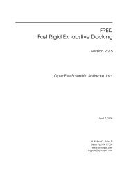
Diagnostic flowchartsIn this section<strong>Troubleshooting</strong> flowcharts ...................................................................................................................... 19<strong>Troubleshooting</strong> flowchartsTo effectively troubleshoot a problem, <strong>HP</strong> recommends that you start with the first flowchart in this section,"Start diagnosis flowchart (on page 20)," and follow the appropriate diagnostic path. If the otherflowcharts do not provide a troubleshooting solution, follow the diagnostic steps in "General diagnosisflowchart (on page 20)." The General diagnosis flowchart is a generic troubleshooting process to be usedwhen the problem is not server-specific or is not easily categorized into the other flowcharts.The available flowcharts include:• Start diagnosis flowchart (on page 20)• General diagnosis flowchart (on page 20)• Power-on problems• Server power-on problems flowchart (on page 22)• p-Class server blade power-on problems flowchart (on page 23)• c-Class server blade power-on problems flowchart (on page 25)• POST problems flowchart (on page 26)• Server and p-Class server blade POST problems flowchart (on page 27)• c-Class server blade POST problems flowchart (on page 28)• Operating system boot problems flowchart (on page 28)• Server fault indications flowchart (on page 29)• Server and p-Class server blade fault indications flowchart (on page 30)• c-Class server blade fault indications flowchart (on page 31)Diagnostic flowcharts 19
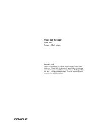
Start diagnosis flowchartUse the following flowchart to start the diagnostic process.General diagnosis flowchartDiagnostic flowcharts 20
The General diagnosis flowchart provides a generic approach to troubleshooting. If you are unsure of theproblem, or if the other flowcharts do not fix the problem, use the following flowchart.Diagnostic flowcharts 21
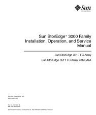
Power-on problems flowchartServer power-on problems flowchartSymptoms:• The server does not power on.• The system power LED is off or amber.• The external health LED is red or amber.• The internal health LED is red or amber.NOTE: For the location of server LEDs and information on their statuses, refer to the server documentation.Possible causes:• Improperly seated or faulty power supply• Loose or faulty power cord• Power source problem• Power-on circuit problem• Improperly seated component or interlock problem• Faulty internal componentDiagnostic flowcharts 22
p-Class server blade power-on problems flowchartSymptoms:• The server does not power on.• The system power LED is off or amber.• The health LED is red or amber.NOTE: For the location of server LEDs and information on their statuses, refer to the server documentation.Possible causes:• Improperly seated or faulty power supplyDiagnostic flowcharts 23
• Loose or faulty power cord• Power source problem• Power-on circuit problem• Improperly seated component or interlock problem• Faulty internal componentDiagnostic flowcharts 24
c-Class server blade power-on problems flowchartSymptoms:• The server does not power on.• The system power LED is off or amber.• The health LED is red or amber.NOTE: For the location of server LEDs and information on their statuses, refer to the server documentation.Possible causes:• Improperly seated or faulty power supply• Loose or faulty power cord• Power source problem• Power on circuit problem• Improperly seated component or interlock problem• Faulty internal componentDiagnostic flowcharts 25
POST problems flowchartSymptoms:• Server does not complete POSTNOTE: The server has completed POST when the system attempts to access the boot device.• Server completes POST with errorsPossible problems:• Improperly seated or faulty internal component• Faulty KVM device• Faulty video deviceDiagnostic flowcharts 26
Server and p-Class server blade POST problems flowchartDiagnostic flowcharts 27
c-Class server blade POST problems flowchartOperating system boot problems flowchartSymptoms:• Server does not boot a previously installed OS• Server does not boot SmartStartPossible causes:• Corrupted OS• Hard drive subsystem problem• Incorrect boot order setting in RBSUThere are two ways to use SmartStart when diagnosing OS boot problems on a server blade:Diagnostic flowcharts 28
• Use iLO to remotely attach virtual devices to mount the SmartStart CD onto the server blade.• Use a local I/O cable and drive to connect to the server blade, and then restart the server blade.Server fault indications flowchartSymptoms:• Server boots, but a fault event is reported by Insight Management Agents (on page 59)• Server boots, but the internal health LED, external health LED, or component health LED is red oramberDiagnostic flowcharts 29
NOTE: For the location of server LEDs and information on their statuses, refer to the server documentation.Possible causes:• Improperly seated or faulty internal or external component• Unsupported component installed• Redundancy failure• System overtemperature conditionServer and p-Class server blade fault indications flowchartDiagnostic flowcharts 30
c-Class server blade fault indications flowchartDiagnostic flowcharts 31
Hardware problemsIn this sectionProcedures for all <strong>ProLiant</strong> servers ............................................................................................................ 32Power problems ..................................................................................................................................... 32General hardware problems.................................................................................................................... 33Internal system problems ......................................................................................................................... 35System open circuits and short circuits ...................................................................................................... 43External device problems ........................................................................................................................ 43Procedures for all <strong>ProLiant</strong> serversThe procedures in this section are comprehensive and include steps about or references to hardwarefeatures that may not be supported by the server you are troubleshooting.Power problemsPower source problemsAction:1. Press the Power On/Standby button to be sure it is on. If the server has a Power On/Standby buttonthat returns to its original position after being pressed, be sure you press the switch firmly.2. Plug another device into the grounded power outlet to be sure the outlet works. Also, be sure thepower source meets applicable standards.3. Replace the power cord with a known functional power cord to be sure it is not faulty.4. Replace the power strip with a known functional power strip to be sure it is not faulty.5. Have a qualified electrician check the line voltage to be sure it meets the required specifications.6. Be sure the proper circuit breaker is in the On position.Power supply problemsAction:1. Be sure no loose connections (on page 15) exist.2. If the power supplies have LEDs, be sure they indicate that each power supply is working properly.Refer to the server documentation. If LEDs indicate a problem with a power supply, replace thepower supply.3. Be sure the system has enough power, particularly if you recently added hardware, such as harddrives. Additional power supplies may be required. Check the system information from the IML anduse the server documentation for product-specific information.Hardware problems 32
UPS problemsUPS is not working properlyAction:1. Be sure the UPS batteries are charged to the proper level for operation. See the UPS documentationfor details.2. Be sure the UPS power switch is in the On position. See the UPS documentation for the location ofthe switch.3. Be sure the UPS software is updated to the latest version. Use the Power Management softwarelocated on the Power Management CD.4. Be sure the power cord is the correct type for the UPS and the country in which the server is located.See the UPS reference guide for specifications.5. Be sure the line cord is connected.6. Be sure each circuit breaker is in the On position, or replace the fuse if needed. If this occursrepeatedly, contact an authorized service provider.7. Check the UPS LEDs to be sure a battery or site wiring problem has not occurred. See the UPSdocumentation.8. If the UPS sleep mode is initiated, disable sleep mode for proper operation. The UPS sleep mode canbe turned off through the configuration mode on the front panel.9. Change the battery to be sure damage was not caused by excessive heat, particularly if a recent airconditioning outage has occurred.NOTE: The optimal operating temperature for UPS batteries is 25°C (77°F). For approximately every 8°C to10°C (16°F to 18°F) average increase in ambient temperature above the optimal temperature, battery life isreduced by 50 percent.Low battery warning is displayedAction:1. Plug the UPS into an AC grounded outlet for at least 24 hours to charge the batteries, and then testthe batteries. Replace the batteries if necessary.2. Be sure the alarm is set appropriately by changing the amount of time given before a low batterywarning. Refer to the UPS documentation for instructions.One or more LEDs on the UPS is redAction: Refer to the UPS documentation for instructions regarding the specific LED to determine the causeof the error.General hardware problemsProblems with new hardwareAction:1. Refer to the server documentation to be sure the hardware being installed is a supported option onthe server. Remove unsupported hardware.Hardware problems 33
2. Refer to the release notes included with the hardware to be sure the problem is not caused by achange to the hardware release. If no documentation is available, refer to the <strong>HP</strong> support website(http://www.hp.com/support).3. Be sure the new hardware is installed properly. Refer to the device, server, and OS documentationto be sure all requirements are met.Common problems include:• Incomplete population of a memory bank• Installation of a processor without a corresponding PPM• Installation of a SCSI device without termination or without proper ID settings• Setting of an IDE device to Primary/Secondary when the other device is set to CS• Connection of the data cable, but not the power cable, of a new device4. Be sure no memory, I/O, or interrupt conflicts exist.5. Be sure no loose connections (on page 15) exist.6. Be sure all cables are connected to the correct locations and are the correct lengths. For moreinformation, refer to the server documentation.7. Be sure other components were not unseated accidentally during the installation of the newhardware component.8. Be sure all necessary software updates, such as device drivers, ROM updates, and patches, areinstalled, current, and the correct version for the hardware installed. For example, if you are using aSmart Array controller, you need the latest Smart Array Controller device driver. Uninstall anyincorrect drivers before installing the correct drivers.9. Run RBSU after boards or other options are installed or replaced to be sure all system componentsrecognize the changes. If you do not run the utility, you may receive a POST error messageindicating a configuration error. After you check the settings in RBSU, save and exit the utility, andthen restart the server. For more information on RBSU, refer to the <strong>HP</strong> ROM-Based Setup Utility User<strong>Guide</strong> on the Documentation CD or the <strong>HP</strong> website (http://www.hp.com/servers/smartstart).10. Be sure all switch settings are set correctly. For additional information about required switch settings,refer to the labels located on the inside of the server access panel or the server documentation.11. Be sure all boards are properly installed in the server.12. Run <strong>HP</strong> Insight Diagnostics (on page 61) to see if it recognizes and tests the device.13. Uninstall the new hardware.Unknown problemAction:1. Disconnect power to the server.2. Following the guidelines and cautionary information in the server documentation, strip the server toits most basic configuration by removing every card or device that is not necessary to start theserver. Keep the monitor connected to view the server startup process.3. Reconnect power, and then power the system on.• If the video does not work, refer to "Video problems (on page 43)."CAUTION: Only authorized technicians trained by <strong>HP</strong> should attempt to remove the system board. If youbelieve the system board requires replacement, contact <strong>HP</strong> Technical Support before proceeding.• If the system fails in this minimum configuration, one of the primary components has failed. If youhave already verified that the processor, PPM, power supply, and memory are working beforegetting to this point, replace the system board. If not, be sure each of those components isworking.Hardware problems 34
• If the system boots and video is working, add each component back to the server one at a time,restarting the server after each component is added to determine if that component is the causeof the problem. When adding each component back to the server, be sure to disconnect powerto the server and follow the guidelines and cautionary information in the server documentation.Third-party device problemsAction:1. Refer to the server and operating system documentation to be sure the server and operating systemsupport the device.2. Be sure the latest device drivers are installed.3. Refer to the device documentation to be sure the device is properly installed. For example, a thirdpartyPCI or PCI-X board may be required to be installed on the primary PCI or PCI-X bus,respectively.Testing the deviceAction:1. Uninstall the device.If the server works with the device removed and uninstalled, a problem exists with the device, theserver does not support the device, or a conflict exists with another device.2. If the device is the only device on a bus, be sure the bus works by installing a different device on thebus.3. Restarting the server each time to determine if the device is working, move the device:a. To a different slot on the same bus (not applicable for PCI Express)b. To a PCI, PCI-X, or PCI Express slot on a different busc. To the same slot in another working server of the same or similar designIf the board works in any of these slots, either the original slot is bad or the board was not properlyseated. Reinsert the board into the original slot to verify.4. If you are testing a board (or a device that connects to a board):a. Test the board with all other boards removed.b. Test the server with only that board removed.CAUTION: Clearing NVRAM deletes the configuration information. Refer to the server documentation forcomplete instructions before performing this operation or data loss could occur.5. Clearing NVRAM can resolve various problems. Clear the NVRAM, but do not use the backup .SCIfile if prompted. Have available any .CFG, .OVL, or .PCF files that are required.Internal system problemsCD-ROM and DVD drive problemsSystem does not boot from the driveAction:1. Be sure the drive boot order in RBSU is set so that the server boots from the CD-ROM drive first.2. If the CD-ROM drive jumpers are set to CS (the factory default), be sure the CD-ROM drive isinstalled as device 0 on the cable so that it is in position for the server to boot from the drive.Hardware problems 35
3. Be sure no loose connections (on page 15) exist.4. Be sure the media from which you are attempting to boot is not damaged and is a bootable CD.5. If attempting to boot from a USB CD-ROM drive:• Refer to the operating system and server documentation to be sure both support booting from aUSB CD-ROM drive.• Be sure legacy support for a USB CD-ROM drive is enabled in RBSU.Data read from the drive is inconsistent, or drive cannot read dataAction:1. Clean the drive and media.2. If a paper or plastic label has been applied to the surface of the CD or DVD in use, remove the labeland any adhesive residue.3. Be sure the inserted CD or DVD format is valid for the drive. For example, be sure you are notinserting a DVD into a drive that only supports CDs.Drive is not detectedAction:1. Be sure no loose connections (on page 15) exist.2. Refer to the drive documentation to be sure cables are connected as required.3. Be sure the cables are working properly. Replace with known functional cables to test whether theoriginal cables were faulty.4. Be sure the correct, current driver is installed.Diskette drive problemsDiskette drive light stays onAction:1. Be sure no loose connections (on page 15) exist.2. Be sure the diskette is not damaged. Run the diskette utility on the diskette (CHKDSK on somesystems).3. Be sure the diskette is properly inserted. Remove the diskette and reinsert correctly into the drive.4. Be sure the diskette drive is cabled properly. Refer to the server documentation.A problem has occurred with a diskette transactionAction: Be sure the directory structure on the diskette is not bad. Run the diskette utility to check forfragmentation (CHKDSK on some systems).Diskette drive cannot read a disketteAction:1. If the diskette is not formatted, format the diskette.2. Check the type of drive you are using and be sure you are using the correct diskette type.Hardware problems 36
Drive is not foundAction: Be sure no loose connections (on page 15) exist with the drive.Non-system disk message is displayedAction:1. Remove the non-system diskette from the drive.2. Check for and disconnect any non-bootable USB devices.Diskette drive cannot write to a disketteAction:1. If the diskette is not formatted, format the diskette.2. Be sure the diskette is not write protected. If it is, use another diskette or remove the write protection.3. Be sure you are attempting to write to the proper drive by checking the drive letter in the pathstatement.4. Be sure enough space is available on the diskette.Tape drive problemsThe following sections include the most common tape drive issues. Actions are listed in the order that theyshould be tried. If the issue is resolved, it is not necessary to complete the remaining actions.All actions may not apply to all tape drives.For detailed tape drive troubleshooting information, see the <strong>HP</strong> website(http://www.hp.com/support/proliantstorage).Stuck tape issueTo download <strong>HP</strong> StorageWorks Library and Tape Tools, see the <strong>HP</strong> website(http://www.hp.com/support/tapetools).Action:1. Manually press the Eject button. Allow up to 10 minutes for the tape to rewind and eject.2. Perform a forced eject:a. Press and hold the Eject button for at least 10 seconds.b. Allow up to 10 minutes for the tape to rewind and eject. The green Ready LED should flash.3. Power cycle the drive. Allow up to 10 minutes for the drive to become ready again.4. Press the Emergency Reset button.5. Check for conflicts in backup software services.6. Check the SCSI/HBA/Driver configuration of the drive.7. Inspect media and cables, and discard any that are faulty or damaged.8. Run the Acceptance Test in <strong>HP</strong> StorageWorks Library and Tape Tools.CAUTION: Running the Acceptance Test overwrites the tape. To avoid overwriting the tape, run the shorterDevice Analysis Test instead.9. Contact <strong>HP</strong> support.Hardware problems 37
Read/write issueAction:1. Run the Acceptance Test in <strong>HP</strong> StorageWorks Library and Tape Tools.CAUTION: Running the Acceptance Test overwrites the tape. To avoid overwriting the tape, run the shorterDevice Analysis Test instead.Backup issue2. Run the Media Validation Test in <strong>HP</strong> StorageWorks Library and Tape Tools.Action:1. Run the Acceptance Test in <strong>HP</strong> StorageWorks Library and Tape Tools.CAUTION: Running the Acceptance Test overwrites the tape. To avoid overwriting the tape, run the shorterDevice Analysis Test instead.Media issue2. Run the Media Validation Test in <strong>HP</strong> StorageWorks Library and Tape Tools.3. Check back-up logs.4. Verify a supported configuration is being used.5. Check for media damage:• Incorrect label placement• Broken, missing, or loose leader pin• Damaged cartridge seam• Usage in incorrect environment6. Check for software issues:a. Check the back-up software.b. Check that virus scanning software is not scheduled to run at the same time as the back-up.7. Verify that a tape can be formatted.Action:1. Verify that the correct media part number is being used.2. Run the Media Validation Test in <strong>HP</strong> StorageWorks Library and Tape Tools.3. Check for media damage:• Incorrect label placement• Broken, missing, or loose leader pin• Damaged cartridge seam• Usage in incorrect environment4. Check if the Tape Error LED is flashing:a. Reload the suspect tape. If the Tape Error LED stops flashing, the problem has cleared.b. Load a new or known good tape. If the Tape Error LED stops flashing, the problem has cleared.c. Reload the suspect tape. If the Tape Error LED flashes, discard the suspect media as faulty.5. Discard any media that has been used at temperatures greater than 45°C (113ºF) or less than 5ºC(41ºF).Hardware problems 38
Hard drive problemsSystem completes POST but hard drive failsAction:1. Be sure no loose connections (on page 15) exist.2. Be sure no device conflict exists.3. Be sure the hard drive is properly cabled and terminated if necessary.4. Be sure the hard drive data cable is working by replacing it with a known functional cable.5. Run Insight Diagnostics ("<strong>HP</strong> Insight Diagnostics" on page 61) and replace failed components asindicated.No hard drives are recognizedAction:1. Be sure no power problems (on page 32) exist.2. Check for loose connections (on page 15).3. Be sure that the controller supports the hard drives being installed.4. Be sure the controller has the most recent firmware.Hard drive is not recognized by the serverAction:1. Check the LEDs on the hard drive to be sure they indicate normal function. Refer to the serverdocumentation or the <strong>HP</strong> website (http://www.hp.com) for information on hard drive LEDs.2. Be sure no loose connections (on page 15) exist.3. Remove the hard drive and be sure the configuration jumpers are set properly.4. If using an array controller, be sure the hard drive is configured in an array. Run the arrayconfiguration utility.5. Be sure the drive is properly configured. Refer to the drive documentation to determine the properconfiguration.6. If it is a non-hot-plug drive, be sure a conflict does not exist with another hard drive. Check for SCSIID conflicts.7. Be sure the correct drive controller drivers are installed.A new hard drive is not recognizedAction:1. Be sure the drive bay is not defective by installing the hard drive in another bay.2. If the drive has just been added, be sure the drive is supported. Refer to the server documentation orthe <strong>HP</strong> website to determine drive support.3. Run Insight Diagnostics ("<strong>HP</strong> Insight Diagnostics" on page 61) and replace failed components asindicated.4. If the drive is a replacement drive on an array controller, make sure that the drive is the same typeand of the same or larger capacity than the original drive.You are unable to access dataAction:Hardware problems 39
1. Be sure the files are not corrupt. Run the repair utility for the operating system.2. Be sure no viruses exist on the server. Run a current version of a virus scan utility.Server response time is slower than usualFan problemsAction: Be sure the hard drive is not full, and increase the amount of free space on the hard drive, ifneeded. It is recommended that hard drives should have a minimum of 15 percent free space.General fan problems are occurringAction:1. Be sure the fans are properly seated and working.a. Follow the procedures and warnings in the server documentation for removing the access panelsand accessing and replacing fans.b. Unseat, and then reseat, each fan according to the proper procedures.c. Replace the access panels, and then attempt to restart the server.2. Be sure the fan configuration meets the functional requirements of the server. Refer to the serverdocumentation.3. Be sure no ventilation problems exist. If you have been operating the server for an extended periodof time with the access panel removed, airflow may have been impeded, causing thermal damage tocomponents. Refer to the server documentation for further requirements.4. Be sure no POST error messages ("POST error messages and beep codes" on page 92) aredisplayed while booting the server that indicate temperature violation or fan failure information.Refer to the server documentation for the temperature requirements for the server.5. Access the IML to see if any event list error messages (on page 124) relating to fans are listed.6. Replace any required non-functioning fans and restart the server. Refer to the server documentationfor specifications on fan requirements.7. Be sure all fan slots have fans or blanks installed. Refer to the server documentation for requirements.8. Verify the fan airflow path is not blocked by cables or other material.Hot-plug fan problems are occurringAction:1. Check the LEDs to be sure the hot-plug fans are working. Refer to the server documentation for LEDinformation.NOTE: For servers with redundant fans, backup fans may spin up periodically to test functionality. This ispart of normal redundant fan operation.2. Be sure no POST error messages ("POST error messages and beep codes" on page 92) aredisplayed.3. Be sure hot-plug fan requirements are being met. Refer to the server documentation.Hardware problems 40
Memory problemsGeneral memory problems are occurringAction:• Isolate and minimize the memory configuration.• Be sure the memory meets the server requirements and is installed as required by the server.Some servers may require that memory banks be fully populated or that all memory within amemory bank must be the same size, type, and speed. Refer to the server documentation todetermine if the memory is installed properly.• Check any server LEDs that correspond to memory slots.• If you are unsure which DIMM has failed, test each bank of DIMMs by removing all otherDIMMs. Then, isolate the failed DIMM by switching each DIMM in a bank with a known workingDIMM.• Remove any third-party memory.• Run <strong>HP</strong> Insight Diagnostics (on page 61) to test the memory.Server is out of memoryAction:1. Be sure the memory is configured properly. Refer to the application documentation to determine thememory configuration requirements.2. Be sure no operating system errors are indicated.3. Be sure a memory count error ("Memory count error exists" on page 41) did not occur. Refer to themessage displaying memory count during POST.Memory count error existsPossible Cause: The memory modules are not installed correctly.Action:1. Be sure the memory modules are supported by the server. Refer to the server documentation.2. Be sure the memory modules have been installed correctly in the right configuration. Refer to theserver documentation.3. Be sure the memory modules are properly seated.4. Be sure no operating system errors are indicated.5. Restart the server and check to see if the error message is still displayed.6. Run Insight Diagnostics ("<strong>HP</strong> Insight Diagnostics" on page 61) and replace failed components asindicated.Server fails to recognize existing memoryAction:1. Reseat the memory.2. Be sure the memory is configured properly. Refer to the server documentation.3. Be sure a memory count error ("Memory count error exists" on page 41) did not occur. Refer to themessage displaying memory count during POST.Hardware problems 41
Server fails to recognize new memoryAction:1. Be sure the memory is the correct type for the server and is installed according to the serverrequirements. Refer to the server documentation or <strong>HP</strong> website (http://www.hp.com).2. Be sure you have not exceeded the memory limits of the server or operating system. Refer to theserver documentation.3. Be sure no Event List error messages (on page 124) are displayed in the IML.4. Be sure the memory is properly seated.5. Be sure no conflicts are occurring with existing memory. Run the server setup utility.6. Test the memory by installing the memory into a known working server. Be sure the memory meetsthe requirements of the new server on which you are testing the memory.7. Replace the memory. Refer to the server documentation.PPM problemsAction: If the PPMs are not integrated on the system board:CAUTION: Do not operate the server for long periods with the access panel open or removed. Operatingthe server in this manner results in improper airflow and improper cooling that can lead to thermal damage.1. If applicable, check the PPM LEDs to identify if a PPM failure occurred. For information on LEDs, referto the server documentation.2. Reseat each PPM, and then restart the server.3. If reseating the PPMs is not effective, remove all but one PPM, restart the server to see if the PPM isworking, and then install each PPM individually, cycling power each time. Follow the warnings andcautionary information in the server documentation.Processor problemsAction:1. If applicable, check the processor LEDs to identify if a PPM failure occurred. For information on LEDs,refer to the server documentation.2. Be sure each processor is supported by the server and is installed properly. Refer to the serverdocumentation for processor requirements.3. Be sure the server ROM is up to date.4. Be sure you are not mixing processor stepping, core speeds, or cache sizes if this is not supportedon the server. Refer to the server documentation for more information.CAUTION: Removal of some processors and heatsinks require special considerations for replacement,while other processors and heatsinks are integrated and cannot be reused once separated. For specificinstructions for the server you are troubleshooting, refer to processor information in the server user guide.5. If the server has only one processor installed, replace it with a known functional processor. If theproblem is resolved after you restart the server, the original processor failed.6. If the server has multiple processors installed, test each processor:a. Remove all but one processor from the server. Replace each with a processor terminator board orblank, if applicable to the server.b. If the server includes PPMs that are not integrated on the system board, remove all PPMs from theserver except for the PPM associated with the remaining processor.Hardware problems 42
c. Replace the remaining processor with a known functional processor. If the problem is resolvedafter you restart the server, a fault exists with one or more of the original processors. Install eachprocessor and its associated PPM (if applicable) one by one, restarting each time, to find thefaulty processor or processors. Be sure the processor configurations at each step are compatiblewith the server requirements.System open circuits and short circuitsAction:CAUTION: Do not operate the server for long periods with the access panel open or removed. Operatingthe server in this manner results in improper airflow and improper cooling that can lead to thermal damage.1. Check the server LEDs to see if any statuses indicate the source of the problem. For LED information,refer to the server documentation.2. Remove all power sources to the server.3. Be sure no loose connections (on page 15) exist in the area.4. Be sure each component in the area is working. Refer to the section for each component in thisguide.If you cannot determine the problem by checking the specific area, perform each of the following actions.Restart the server after each action to see if the problem has been corrected.• Reseat all I/O expansion boards.• Be sure no loose connections (on page 15) exist in the rest of the server, particularly with the cablesthat connect to the system board.• Be sure no foreign material exists, such as screws, bits, or slot bracket blanks, that may be shortcircuiting components.External device problemsVideo problemsScreen is blank for more than 60 seconds after you power up the serverAction:1. Be sure the monitor power cord is plugged into a working grounded (earthed) AC outlet.2. Power up the monitor and be sure the monitor light is on, indicating that the monitor is receivingpower.3. Be sure the monitor is cabled to the intended server or KVM connection.4. Be sure no loose connections (on page 15) exist.• For rack-mounted servers, check the cables to the KVM switch and be sure the switch is correctlyset for the server. You may need to connect the monitor directly to the server to be sure the KVMswitch has not failed.• For tower model servers, check the cable connection from the monitor to the server, and thenfrom the server to the power outlet.5. Press any key, or type the password, and wait a few moments for the screen to activate to be surethe energy saver feature is not in effect.6. Be sure the video driver is current. Refer to the third-party video adapter documentation for driverrequirements.Hardware problems 43
7. Be sure a video expansion board, such as a RILOE board, has not been added to replace onboardvideo, making it seem like the video is not working. Disconnect the video cable from the onboardvideo, and then reconnect it to the video jack on the expansion board.NOTE: All servers automatically bypass onboard video when a video expansion board is present.8. Press any key, or type the password, and wait a few moments for the screen to activate to be surethe power-on password feature is not in effect. You can also tell if the power-on password is enabledif a key symbol is displayed on the screen when POST completes.If you do not have access to the password, you must disable the power-on password by using thePassword Disable switch on the system board. Refer to the server documentation.9. If the video expansion board is installed in a PCI hot-plug slot, be sure the slot has power bychecking the power LED on the slot, if applicable. Refer to the server documentation.10. Be sure the server and the OS support the video expansion board.Monitor does not function properly with energy saver featuresAction: Be sure the monitor supports energy saver features, and if it does not, disable the features.Video colors are wrongAction:• Be sure the 15-pin VGA cable is securely connected to the correct VGA port on the server and to themonitor.• Be sure the monitor and any KVM switch are compatible with the VGA output of the server.Slow-moving horizontal lines are displayedAction: Be sure magnetic field interference is not occurring. Move the monitor away from other monitorsor power transformers.Mouse and keyboard problemsAction:1. Be sure no loose connections (on page 15) exist. If a KVM switching device is in use, be sure theserver is properly connected to the switch.• For rack-mounted servers, check the cables to the switch box and be sure the switch is correctlyset for the server.• For tower model servers, check the cable connection from the input device to the server.2. If a KVM switching device is in use, be sure all cables and connectors are the proper length and aresupported by the switch. Refer to the switch documentation.3. Be sure the current drivers for the operating system are installed.4. Be sure the device driver is not corrupted by replacing the driver.5. Restart the system and check whether the input device functions correctly after the server restarts.6. Replace the device with a known working equivalent device (another similar mouse or keyboard).• If the problem still occurs with the new mouse or keyboard, the connector port on the system I/Oboard is defective. Replace the board.• If the problem no longer occurs, the original input device is defective. Replace the device.7. Be sure the keyboard or mouse is connected to the correct port. Determine whether the keyboardlights flash at POST or the NumLock LED illuminates. If not, change port connections.8. Be sure the keyboard or mouse is clean.Hardware problems 44
Audio problemsAction: Be sure the server speaker is connected. Refer to the server documentation.Printer problemsPrinter does not printAction:1. Be sure the printer is powered up and online.2. Be sure no loose connections (on page 15) exist.3. Be sure the correct printer drivers are installed.Printer output is garbledAction: Be sure the correct printer drivers are installed.Local I/O cable problemsNOTE: The local I/O cable is used only with <strong>HP</strong> <strong>ProLiant</strong> p-Class server blades.Action: If the local I/O cable does not have hot-plug functionality, be sure you are not using a PS/2keyboard or mouse. With a PS/2 keyboard or mouse, the local I/O cable cannot be connected as a hotplugdevice. Connect the local I/O cable before booting the server, or switch to USB devices (ifsupported) to use the local I/O cable hot-plug functionality.Modem problemsNo dial tone existsAction:1. Be sure the cables are plugged in as specified in the modem documentation.2. Connect a working telephone directly to the wall jack, and then test the line for a dial tone.3. If no dial tone is detected, the phone line is not working. Contact the local telephone company andarrange to correct the problem.No response occurs when you type AT commandsAction: Reconfigure the COM port address for the modem.1. Be sure the communications software is set to the COM port to which the modem is connected.2. Check IRQ settings in the software and on the modem to be sure no conflict exists.3. Type AT&F at the command prompt to reset the modem to factory-default settings.4. Be sure you are in terminal mode and not MS-DOS mode.5. Refer to the <strong>HP</strong> website (http://www.hp.com) for a complete list of AT commands.AT commands are not visibleAction: Set the echo command to On using the AT command ATE.Hardware problems 45
Data is displayed as garbled characters after the connection is establishedAction:1. Be sure both modems have the same settings, including speed, data, parity, and stop bits.2. Be sure the software is set for the correct terminal emulation.a. Reconfigure the software correctly.b. Restart the server.c. Run the communications software, checking settings and making corrections where needed.d. Restart the server, and then reestablish the modem connection.Modem does not answer an incoming callAction:1. Enable the auto-answer option in the communications software.2. Be sure an answering machine is not answering the line before the modem is able to answer.a. Turn off the answering machine.orReconfigure the auto-answer option to respond in fewer rings than the answering machine.b. Restart the server, and then reattempt the connection.Modem does not connect to another modemAction:1. Be sure a dial tone exists.2. Be sure the line is not in use at another extension before using it.3. Be sure you are dialing the correct telephone number.4. Be sure the modem on the other end is working.Modem disconnects while onlineAction:1. Be sure no loose connections (on page 15) exist.2. Be sure no line interference exists. Retry the connection by dialing the number several times. Ifconditions remain poor, contact the telephone company to have the line tested.3. Be sure an incoming call is not breaking the connection due to call waiting. Disable call waiting,and then reestablish the connection.AT command initialization string is not workingAction: Use the most basic string possible to perform the task. The default initialization string isAT&F&C1&D2&K3.Connection errors are occurringAction:1. Check the maximum baud rate for the modem to which you are connecting, and then change thebaud rate to match.2. If the line you are accessing requires error control to be turned off, do so using the AT commandAT&Q6%C0.Hardware problems 46
3. Be sure no line interference exists. Retry the connection by dialing the number several times. Ifconditions remain poor, contact the telephone company to have the line tested.4. Be sure the modem is current and compliant with CCITT and Bell standards. Replace with asupported modem if needed.You are unable to connect to an online subscription serviceAction:1. If the line you are accessing requires error control to be turned off, do so using the AT commandAT&Q6%C0.2. If the ISP you are accessing requires access at a decreased baud rate, reconfigure thecommunications software to correct the connection baud rate to match the ISP.3. If this does not work, force a slower baud rate (14400 baud) with the AT commandAT&Q6N0S37=11.You are unable to connect at 56 KbpsAction:1. Find out the maximum baud rate at which the ISP connects, and change the settings to reflect this.Reattempt to connect at a lower baud rate.2. Be sure no line interference exists. Retry the connection by dialing the number several times. Ifconditions remain poor, contact the telephone company to have the line tested.Network controller problemsNetwork controller is installed but not workingAction:1. Check the network controller LEDs to see if any statuses indicate the source of the problem. For LEDinformation, refer to the network controller documentation.2. Be sure no loose connections (on page 15) exist.3. Be sure the network cable is working by replacing it with a known functional cable.4. Be sure a software problem has not caused the failure. Refer to the operating system documentationfor guidelines on adding or replacing PCI Hot Plug devices, if applicable.5. Be sure the server and operating system support the controller. Refer to the server and operatingsystem documentation.6. Be sure the controller is enabled in RBSU.7. Check the PCI Hot Plug power LED to be sure the PCI slot is receiving power, if applicable.8. Be sure the server ROM is up to date.9. Be sure the controller drivers are up to date.10. Be sure a valid IP address is assigned to the controller and that the configuration settings are correct.11. Run Insight Diagnostics ("<strong>HP</strong> Insight Diagnostics" on page 61) and replace failed components asindicated.Network controller has stopped workingAction:1. Check the network controller LEDs to see if any statuses indicate the source of the problem. For LEDinformation, refer to the network controller documentation.Hardware problems 47
2. Be sure the correct network driver is installed for the controller and that the driver file is notcorrupted. Reinstall the driver.3. Be sure no loose connections (on page 15) exist.4. Be sure the network cable is working by replacing it with a known functional cable.5. Check the PCI Hot Plug power LED to be sure the PCI slot is receiving power, if applicable.6. Be sure the network controller is not damaged.7. Run Insight Diagnostics ("<strong>HP</strong> Insight Diagnostics" on page 61) and replace failed components asindicated.Network controller stopped working when an expansion board was addedAction:1. Be sure no loose connections (on page 15) exist.2. Be sure the server and operating system support the controller. Refer to the server and operatingsystem documentation.3. Be sure the new expansion board has not changed the server configuration, requiring reinstallationof the network driver.a. Uninstall the network controller driver for the malfunctioning controller in the operating system.b. Restart the server and run RBSU. Be sure the server recognizes the controller and that resourcesare available for the controller.c. Restart the server, and then reinstall the network driver.4. Refer to the operating system documentation to be sure the correct drivers are installed.5. Refer to the operating system documentation to be sure that the driver parameters match theconfiguration of the network controller.Problems are occurring with the network interconnect bladesAction: Be sure the network interconnect blades are properly seated and connected.Hardware problems 48
Software problemsIn this sectionOperating system problems and resolutions............................................................................................... 49Application software problems................................................................................................................. 52Remote ROM flash problems.................................................................................................................... 52The best sources of information for software problems are the operating system and application softwaredocumentation, which may also point to fault detection tools that report errors and preserve the systemconfiguration.Other useful resources include <strong>HP</strong> Insight Diagnostics (on page 61) and <strong>HP</strong> SIM ("<strong>HP</strong> Systems InsightManager" on page 59). Use either utility to gather critical system hardware and software information andto help with problem diagnosis.IMPORTANT: This guide provides information for multiple servers. Some information may not apply to theserver you are troubleshooting. Refer to the server documentation for information on procedures, hardwareoptions, software tools, and operating systems supported by the server.Refer to "Software tools and solutions (on page 54)" for more information.Operating system problems and resolutionsOperating system problemsOperating system locks upAction: Scan for viruses with an updated virus scan utility.General protection fault occursA general protection fault, or general protection error, occurs when the Microsoft operating systemterminates suddenly with an error, including but not limited to:• Miscalculating the amount of RAM needed for an allocation• Transferring execution to a segment that is not executable• Writing to a read-only or a code segment• Loading a bad value into a segment register• Using a null pointerA GPF is immediately identifiable by a blue screen with white text, and the text may contain informationthat identifies the problem.Action:• Remove any newly installed software or hardware to verify that they are not the cause.• Boot the server in Safe Mode or Last Known Good Configuration.Software problems 49
If neither of these actions resolve the problem, contact an authorized service provider. For moreinformation about debugging tools or specific GPF messages, refer to the Microsoft website(http://www.microsoft.com/whdc/devtools/debugging/default.mspx).Errors are displayed in the error logAction: Follow the information provided in the error log, and then refer to the operating systemdocumentation.Problems occur after the installation of a service packAction: Follow the instructions for updating the operating system ("Operating system updates" on page50).NetWare attempts to load MEGA4 XX.HAM or 120PCI.HAM during installation, and a RILOE IIboard is installedAction: No action is required. This occurrence does not impact the installation of NetWare.During installation of Sun Solaris, the system locks up or a panic error occursAction: Disable ACPI support in Sun Solaris. Refer to the Sun website (http://www.sun.com) fordocumentation on how to disable ACPI.Operating system issues with Intel ® dual-core processors (Hyper-Threading enabled)Some versions of Microsoft® Windows® and distributions of Linux may hang during OS installation, failto complete OS installation, or fail to boot after installation on servers with either three or four Intel® dualcoreprocessors installed.Action:Microsoft® Windows Server 2003-based media• System may hang during installation or during boot. Windows Server 2003 SP1 Slipstream doesnot exhibit this issue.• If SP1 Slipstream media is not available, the base media installation can be performed using one ofthe following methods:• Install the OS with only one or two processor(s)• Disable Hyper-Threading in RBSU, then apply SP1 before adding the additional processor(s) andre-enabling Hyper-ThreadingLinux distributions• Additional information and the appropriate solutions for the Linux distributions (if any) can be foundat the <strong>HP</strong> website (http://h18004.www1.hp.com/products/servers/linux/processor-notes.html).Operating system updatesUse care when applying operating system updates (Service Packs, hotfixes, and patches). Beforeupdating the operating system, read the release notes for each update. If you do not require specific fixesfrom the update, it is recommended that you do not apply the updates. Some updates overwrite filesspecific to <strong>HP</strong>.If you decide to apply an operating system update:1. Perform a full system backup.2. Apply the operating system update, using the instructions provided.Software problems 50
3. Install the current drivers.If you apply the update and have problems, refer to the Software and Drivers Download website(http://h18007.www1.hp.com/support/files/server) to find files to correct the problems.Restoring to a backed-up versionIf you recently upgraded the operating system or software and cannot resolve the problem, you can tryrestoring a previously saved version of the system. Before restoring the backup, make a backup of thecurrent system. If restoring the previous system does not correct the problem, you can restore the currentset to be sure you do not lose additional functionality.Refer to the documentation provided with the backup software.When to Reconfigure or Reload SoftwareIf all other options have not resolved the problem, consider reconfiguring the system. Before you take thisstep:1. Weigh the projected downtime of a software reload against the time spent troubleshootingintermittent problems. It may be advantageous to start over by removing and reinstalling the problemsoftware, or in some cases by using the System Erase Utility and reinstalling all system software.CAUTION: Perform a backup before running the System Erase Utility. The utility sets the system to itsoriginal factory state, deletes the current hardware configuration information, including array setup and diskpartitioning, and erases all connected hard drives completely. Refer to the instructions for using this utility.2. Be sure the server has adequate resources (processor speed, hard drive space, and memory) for thesoftware.3. Be sure the server ROM is current and the configuration is correct.4. Be sure you have printed records of all troubleshooting information you have collected to this point.5. Be sure you have two good backups before you start. Test the backups using a backup utility.6. Check the operating system and application software resources to be sure you have the latestinformation.7. If the last-known functioning configuration does not work, try to recover the system with operatingsystem recovery software:• Microsoft® operating systems:Windows Server 2003—Automated System Recovery Diskette. If the operating system wasfactory-installed, click Start>All Programs>Accessories>System Tools to access thebackup utility. Refer to the operating system documentation for more information.Windows® 2000—Emergency Repair Diskette. If the operating system was factory-installed,click Start>Programs>System Tools to access the Emergency Repair Disk Utility. Refer tothe operating system documentation for more information.• Novell NetWare—Repair traditional volumes with VREPAIR. On NetWare 5.X systems, repairNSS volumes with the NSS menu command, and on NetWare 6 systems, repair NSS volumesusing the NSS/PoolVerify command followed by the NSS/PoolRebuild command, ifnecessary. Refer to the NetWare documentation for more information.• Caldera UnixWare and SCO OpenServer from Caldera—Emergency boot diskette. Refer to theCaldera UnixWare or SCO OpenServer from Caldera documentation for more information.• Sun Solaris—Device Configuration Assistant boot diskette. Refer to the Solaris documentation formore information.• IBM OS/2—Power up the server from the startup diskettes. Refer to the OS/2 documentation formore information.Software problems 51
• Linux—Refer to the operating system documentation for information.Linux operating systemsFor troubleshooting information specific to Linux operating systems, refer to the Linux for <strong>ProLiant</strong> website(http://h18000.www1.hp.com/products/servers/linux).Application software problemsSoftware locks upAction:1. Check the application log and operating system log for entries indicating why the software failed.2. Check for incompatibility with other software on the server.3. Check the support website of the software vendor for known problems.4. Review log files for changes made to the server which may have caused the problem.5. Scan the server for viruses with an updated virus scan utility.Errors occur after a software setting is changedAction: Check the system logs to determine what changes were made, and then change settings to theoriginal configuration.Errors occur after the system software is changedAction: Change settings to the original configuration. If more than one setting was changed, change thesettings one at a time to isolate the cause of the problem.Errors occur after an application is installedAction:• Check the application log and operating system log for entries indicating why the software failed.• Check system settings to determine if they are the cause of the error. You may need to obtain thesettings from the server setup utility and manually set the software switches. Refer to the applicationdocumentation, the vendor website, or both.• Check for overwritten files. Refer to the application documentation to find out which files are addedby the application.• Reinstall the application.• Be sure you have the most current drivers.Remote ROM flash problemsGeneral remote ROM flash problems are occurringAction: Be sure you follow these requirements for using the Remote ROM flash utility:• A local administrative client system that is running the Microsoft® Windows NT® 4.0,Windows® 2000, or Windows Server 2003 operating systemSoftware problems 52
• One or more remote servers with system ROMs requiring upgrade• An administrative user account on each target system. The administrative account must have thesame username and password as the local administrative client system.• All target systems are connected to the same network and use protocols that enable them to be seenfrom the administrative client.• Each target system has a system partition that is at least 32 MB in size.• Verification that the ROM version to which you are upgrading can be used for all the servers orarray controllers that you are upgrading.• Follow the instructions for the Remote ROM Flash procedure that accompany the software.Command-line syntax errorIf the correct command-line syntax is not used, an error message describing the incorrect syntax isdisplayed and the program exits. Correct the syntax, and then restart the process.Access denied on target computerIf you specify a networked target computer for which you do not have administrative privileges, an errormessage is displayed describing the problem, and then the program exits. Obtain administrativeprivileges for the target computer, and then restart the process. Be sure the remote registry service isrunning on a Windows®-based system.Invalid or incorrect command-line parametersIf incorrect parameters are passed into command-line options, an error message describing the invalid orincorrect parameter is displayed and the program exits (Example: Invalid source path for systemconfiguration or ROMPaq files). Correct the invalid parameter, and then restart the process.Network connection fails on remote communicationBecause network connectivity cannot be guaranteed, it is possible for the administrative client to becomedisconnected from the target server during the ROM flash preparation. If any remote connectivityprocedure fails during the ROM flash online preparation, the ROM flash does not occur for the targetsystem. An error message describing the broken connection displays and the program exits. Attempt toascertain and correct the cause of connection failure, and then restart the process.Failure occurs during ROM flashAfter the online flash preparation has been successfully completed, the system ROM is flashed offline. Theflash cannot be interrupted during this process, or the ROM image is corrupted and the server does notstart. The most likely reason for failure is a loss of power to the system during the flash process. InitiateROMPaq disaster recovery procedures.Target system is not supportedIf the target system is not listed in the supported servers list, an error message is displayed and theprogram exits. Only supported systems can be upgraded using the Remote ROM Flash utility. To see if theserver is supported, refer to the Software and Drivers Download website(http://h18007.www1.hp.com/support/files/server).Software problems 53
Software tools and solutionsIn this sectionConfiguration tools ................................................................................................................................. 54Management tools.................................................................................................................................. 58Diagnostic tools ..................................................................................................................................... 61Remote support and analysis tools............................................................................................................ 63Keeping the system current ...................................................................................................................... 63Firmware maintenance............................................................................................................................ 65Configuration toolsArray Configuration UtilityACU is a browser-based utility with the following features:• Runs as a local application or remote service• Supports online array capacity expansion, logical drive extension, assignment of online spares, andRAID or stripe size migration• Suggests the optimum configuration for an unconfigured system• Provides different operating modes, enabling faster configuration or greater control over theconfiguration options• Remains available any time that the server is on• Displays on-screen tips for individual steps of a configuration procedureFor optimum performance, the minimum display settings are 800 × 600 resolution and 256 colors.<strong>Servers</strong> running Microsoft® operating systems require Internet Explorer 5.5 (with Service Pack 1) or later.For Linux servers, refer to the README.TXT file for additional browser and support information.For more information, refer to the <strong>HP</strong> Array Configuration Utility User <strong>Guide</strong> on the Documentation CD orthe <strong>HP</strong> website (http://www.hp.com).SmartStart softwareSmartStart is a collection of software that optimizes single-server setup, providing a simple and consistentway to deploy server configuration. SmartStart has been tested on many <strong>ProLiant</strong> server products,resulting in proven, reliable configurations.SmartStart assists the deployment process by performing a wide range of configuration activities,including:• Configuring hardware using embedded configuration utilities, such as RBSU and ORCA• Preparing the system for installing "off-the-shelf" versions of leading operating system software• Installing optimized server drivers, management agents, and utilities automatically with everyassisted installation• Testing server hardware using the Insight Diagnostics Utility ("<strong>HP</strong> Insight Diagnostics" on page 61)Software tools and solutions 54
• Installing software drivers directly from the CD. With systems that have internet connection, theSmartStart Autorun Menu provides access to a complete list of <strong>ProLiant</strong> system software.• Enabling access to the Array Configuration Utility (on page 54), Array Diagnostic Utility (on page63), and Erase Utility (on page 59)SmartStart is included in the <strong>HP</strong> <strong>ProLiant</strong> Essentials Foundation Pack. For more information aboutSmartStart software, refer to the <strong>HP</strong> <strong>ProLiant</strong> Essentials Foundation Pack or the <strong>HP</strong> website(http://www.hp.com/servers/smartstart).SmartStart Scripting ToolkitThe SmartStart Scripting Toolkit is a server deployment product that delivers an unattended automatedinstallation for high-volume server deployments. The SmartStart Scripting Toolkit is designed to support<strong>ProLiant</strong> BL, ML, and DL servers. The toolkit includes a modular set of utilities and important documentationthat describes how to apply these new tools to build an automated server deployment process.Using SmartStart technology, the Scripting Toolkit provides a flexible way to create standard serverconfiguration scripts. These scripts are used to automate many of the manual steps in the serverconfiguration process. This automated server configuration process cuts time from each server deployed,making it possible to scale server deployments to high volumes in a rapid manner.For more information, and to download the SmartStart Scripting Toolkit, refer to the <strong>HP</strong> website(http://www.hp.com/servers/sstoolkit).<strong>HP</strong> ROM-Based Setup UtilityUsing RBSURBSU, an embedded configuration utility, performs a wide range of configuration activities that mayinclude:• Configuring system devices and installed options• Displaying system information• Selecting the primary boot controller• Configuring memory options• Language selectionFor more information on RBSU, refer to the <strong>HP</strong> ROM-Based Setup Utility User <strong>Guide</strong> on the DocumentationCD or the <strong>HP</strong> website (http://www.hp.com/servers/smartstart).The first time you power up the server, the system prompts you to enter RBSU and select a language.Default configuration settings are made at this time and can be changed later. Most of the features inRBSU are not required to set up the server.To navigate RBSU, use the following keys:• To access RBSU, press the F9 key during power up when prompted in the upper right corner of thescreen.• To navigate the menu system, use the arrow keys.• To make selections, press the Enter key.IMPORTANT: RBSU automatically saves settings when you press the Enter key. The utility does not promptyou for confirmation of settings before you exit the utility. To change a selected setting, you must select adifferent setting and press the Enter key.Software tools and solutions 55
Auto-configuration processThe auto-configuration process automatically runs when you boot the server for the first time. During thepower-up sequence, the system ROM automatically configures the entire system without needing anyintervention. During this process, the ORCA utility, in most cases, automatically configures the array to adefault setting based on the number of drives connected to the server.NOTE: The server may not support all the following examples.NOTE: If the boot drive is not empty or has been written to in the past, ORCA does not automaticallyconfigure the array. You must run ORCA to configure the array settings.Boot optionsDrives installed Drives used RAID level1 1 RAID 02 2 RAID 13, 4, 5, or 6 3, 4, 5, or 6 RAID 5More than 6 0 NoneTo change any ORCA default settings and override the auto-configuration process, press the F8 key whenprompted.By default, the auto-configuration process configures the system for the English language. To change anydefault settings in the auto-configuration process (such as the settings for language, operating system, andprimary boot controller), execute RBSU by pressing the F9 key when prompted. After the settings areselected, exit RBSU and allow the server to reboot automatically.For more information, refer to the <strong>HP</strong> ROM-Based Setup Utility User <strong>Guide</strong> on the Documentation CD orthe <strong>HP</strong> website (http://www.hp.com/servers/smartstart).After the auto-configuration process completes, or after the server reboots upon exit from RBSU, the POSTsequence runs, and then the boot option screen is displayed. This screen is visible for several secondsbefore the system attempts to boot from a diskette, CD, or hard drive. During this time, the menu on thescreen allows you to install an operating system or make changes to the server configuration in RBSU.BIOS Serial ConsoleBIOS Serial Console allows you to configure the serial port to view POST error messages and run RBSUremotely through a serial connection to the server COM port. The server that you are remotely configuringdoes not require a keyboard and mouse.For more information about BIOS Serial Console, refer to the BIOS Serial Console User <strong>Guide</strong> on theDocumentation CD or the <strong>HP</strong> website (http://www.hp.com/servers/smartstart).Configuring online spare memoryTo configure online spare memory:1. Install the required DIMMs.2. Access RBSU by pressing the F9 key during power-up when the prompt is displayed in the upperright corner of the screen.3. Select System Options.4. Select Advanced Memory Protection.5. Select Online Spare with Advanced ECC Support.6. Press the Enter key.Software tools and solutions 56
7. Press the Esc key to exit the current menu, or press the F10 key to exit RBSU.For more information on online spare memory, refer to the white paper on the <strong>HP</strong> website(http://h18000.www1.hp.com/products/servers/technology/memoryprotection.html).Option ROM Configuration for ArraysBefore installing an operating system, you can use the ORCA utility to create the first logical drive, assignRAID levels, and establish online spare configurations.The utility also provides support for the following functions:• Reconfiguring one or more logical drives• Viewing the current logical drive configuration• Deleting a logical drive configuration• Setting the controller to be the boot controllerIf you do not use the utility, ORCA will default to the standard configuration.For more information regarding array controller configuration, refer to the controller user guide.For more information regarding the default configurations that ORCA uses, refer to the <strong>HP</strong> ROM-BasedSetup Utility User <strong>Guide</strong> on the Documentation CD.<strong>HP</strong> <strong>ProLiant</strong> Essentials Rapid Deployment PackThe RDP software is the preferred method for rapid, high-volume server deployments. The RDP softwareintegrates two powerful products: Altiris Deployment Solution and the <strong>HP</strong> <strong>ProLiant</strong> Integration Module.The intuitive graphical user interface of the Altiris Deployment Solution console provides simplified pointand-clickand drag-and-drop operations that enable you to deploy target servers, including server blades,remotely. It enables you to perform imaging or scripting functions and maintain software images.For more information about the RDP, refer to the <strong>HP</strong> <strong>ProLiant</strong> Essentials Rapid Deployment Pack CD orrefer to the <strong>HP</strong> website (http://www.hp.com/servers/rdp).Re-entering the server serial number and product IDAfter you replace the system board, you must re-enter the server serial number and the product ID.1. During the server startup sequence, press the F9 key to access RBSU.2. Select the System Options menu.3. Select Serial Number. The following warning is displayed:WARNING! WARNING! WARNING! The serial number is loaded into the systemduring the manufacturing process and should NOT be modified. This optionshould only be used by qualified service personnel. This value shouldalways match the serial number sticker located on the chassis.4. Press the Enter key to clear the warning.5. Enter the serial number and press the Enter key.6. Select Product ID.7. Enter the product ID and press the Enter key.8. Press the Esc key to close the menu.9. Press the Esc key to exit RBSU.10. Press the F10 key to confirm exiting RBSU. The server will automatically reboot.Software tools and solutions 57
Management CDThe Management CD contains the latest tools available for easily managing the server, such as <strong>HP</strong> SIM("<strong>HP</strong> Systems Insight Manager" on page 59) and Management Agents (on page 59).Run the Management CD shipped with the server. Refer to the Management CD user documentation aswell as the <strong>ProLiant</strong> Server Management website (http://www.hp.com/servers/manage).Management toolsAutomatic Server RecoveryASR is a feature that causes the system to restart when a catastrophic operating system error occurs, suchas a blue screen, ABEND, or panic. A system fail-safe timer, the ASR timer, starts when the SystemManagement driver, also known as the Health Driver, is loaded. When the operating system isfunctioning properly, the system periodically resets the timer. However, when the operating system fails,the timer expires and restarts the server.ASR increases server availability by restarting the server within a specified time after a system hang orshutdown. At the same time, the <strong>HP</strong> SIM console notifies you by sending a message to a designatedpager number that ASR has restarted the system. You can disable ASR from the <strong>HP</strong> SIM console orthrough RBSU.ROMPaq utilityFlash ROM enables you to upgrade the firmware (BIOS) with system or option ROMPaq utilities. Toupgrade the BIOS, insert a ROMPaq diskette into the diskette drive and boot the system.The ROMPaq utility checks the system and provides a choice (if more than one exists) of available ROMrevisions. This procedure is the same for both system and option ROMPaq utilities.For more information about the ROMPaq utility, refer to the <strong>HP</strong> website(http://www.hp.com/servers/manage).Remote Insight Lights-Out Edition IIRILOE II enables browser access to servers through a hardware-based, OS-independent graphical remoteconsole. Some of the features include virtual diskette drive and power button, server management throughany standard browser, dedicated LAN connectivity, automatic network configuration, external powerbackup, group administration, and functions available with the Remote Insight Board.For more information about RILOE II features, refer to the Remote Insight Lights-Out Edition User <strong>Guide</strong> onthe Documentation CD or on the <strong>HP</strong> website (http://www.hp.com/servers/lights-out).Integrated Lights-Out technologyThe iLO and iLO 2 subsystem is a standard component of selected <strong>ProLiant</strong> servers that provides serverhealth and remote server manageability. The iLO and iLO 2 subsystem includes an intelligentmicroprocessor, secure memory, and a dedicated network interface. This design makes iLO and iLO 2independent of the host server and its operating system. The iLO and iLO 2 subsystem provides remoteaccess to any authorized network client, sends alerts, and provides other server management functions.Using iLO and iLO 2, you can:• Remotely power up, power down, or reboot the host server.• Send alerts from iLO and iLO 2 regardless of the state of the host server.Software tools and solutions 58
Erase Utility• Access advanced troubleshooting features through the iLO and iLO 2 interface.• Diagnose iLO and iLO 2 using <strong>HP</strong> SIM through a web browser and SNMP alerting.For more information about iLO and iLO 2 features, refer to the iLO and iLO 2 documentation on theDocumentation CD or on the <strong>HP</strong> website (http://www.hp.com/servers/lights-out).CAUTION: Perform a backup before running the System Erase Utility. The utility sets the system to itsoriginal factory state, deletes the current hardware configuration information, including array setup and diskpartitioning, and erases all connected hard drives completely. Refer to the instructions for using this utility.Run the Erase Utility if you must erase the system for the following reasons:• You want to install a new operating system on a server with an existing operating system.• You encounter an error when completing the steps of a factory-installed operating system installation.The Erase Utility can be accessed from the Maintenance Utilities menu of the SmartStart CD("SmartStart software" on page 54).StorageWorks library and tape tools<strong>HP</strong> StorageWorks L&TT provides functionality for firmware downloads, verification of device operation,maintenance procedures, failure analysis, corrective service actions, and some utility functions. It alsoprovides seamless integration with <strong>HP</strong> hardware support by generating and emailing support tickets thatdeliver a snapshot of the storage system.For more information, and to download the utility, refer to the StorageWorks L&TT website(http://h18006.www1.hp.com/products/storageworks/ltt).<strong>HP</strong> Systems Insight Manager<strong>HP</strong> SIM is a web-based application that allows system administrators to accomplish normal administrativetasks from any remote location, using a web browser. <strong>HP</strong> SIM provides device management capabilitiesthat consolidate and integrate management data from <strong>HP</strong> and third-party devices.IMPORTANT: You must install and use <strong>HP</strong> SIM to benefit from the Pre-Failure Warranty for processors,SAS and SCSI hard drives, and memory modules.For additional information, refer to the Management CD in the <strong>HP</strong> <strong>ProLiant</strong> Essentials Foundation Pack orthe <strong>HP</strong> SIM website (http://www.hp.com/go/hpsim).Management AgentsManagement Agents provide the information to enable fault, performance, and configurationmanagement. The agents allow easy manageability of the server through <strong>HP</strong> SIM software, and thirdpartySNMP management platforms. Management Agents are installed with every SmartStart assistedinstallation or can be installed through the <strong>HP</strong> PSP. The Systems Management homepage provides statusand direct access to in-depth subsystem information by accessing data reported through the ManagementAgents. For additional information, refer to the Management CD in the <strong>HP</strong> <strong>ProLiant</strong> Essentials FoundationPack or the <strong>HP</strong> website (http://www.hp.com/servers/manage).<strong>HP</strong> <strong>ProLiant</strong> Essentials Virtualization Management SoftwareThe <strong>ProLiant</strong> Essentials Virtual Machine Management Pack and <strong>ProLiant</strong> Essentials Server Migration Packplug-ins extend <strong>HP</strong> Systems Insight Manager capabilities to manage virtual machines.Software tools and solutions 59
The Virtual Machine Management Pack provides the following functionality:• Central management and control of VMware® and Microsoft® virtual machines with physical host tovirtual machine association• Easy identification of VMs or host servers reaching high CPU, memory, or disk utilization levels• Highly flexible move capabilities that enable live moves and moves to dissimilar host resources• Back up, template, and alternate host capabilities that enable restoration of VMs on any availablehostThe Server Migration Pack automates the manual processes required for migrating servers betweenphysical or virtual platforms (P2V, V2P, and V2V), enabling easy migration to appropriate physical orvirtual platforms that meet performance and capacity requirements.For more information about virtualization management software, see the <strong>HP</strong> website(http://www.hp.com/go/vmmanage).<strong>HP</strong> <strong>ProLiant</strong> Essentials Server Migration Pack - Physical to <strong>ProLiant</strong> EditionThe <strong>HP</strong> <strong>ProLiant</strong> Essentials Server Migration Pack – Physical to <strong>ProLiant</strong> Edition (SMP – P2P) softwareenables administrators to upgrade or replace an existing server. SMP – P2P is an automated, accurate,and affordable tool that migrates existing servers and their content to the latest server technologies.SMP – P2P automates the migration of the operating system, applications, and data from one server toanother without errors, eliminating the need for manual redeployment of these elements on the newserver. During the migration process, the software automatically removes old drivers and loads newdrivers on the destination server. The wizard-based user interface simplifies migration and requires noadditional training.For more information about the SMP – P2P, see the <strong>HP</strong> website (http://www.hp.com/go/p2p).<strong>HP</strong> BladeSystem Essentials Insight Control Data Center Edition<strong>HP</strong> BladeSystem Essentials Insight Control Data Center Edition is an integrated suite of software thatsimplifies the management of <strong>HP</strong> BladeSystem infrastructures. Using a wizard-based installer, InsightControl Data Center Edition installs and configures <strong>HP</strong> Systems Insight Manager (<strong>HP</strong> SIM) and <strong>HP</strong> <strong>ProLiant</strong>Essentials management software rapidly and consistently, reducing manual procedures and enabling afaster deployment of production <strong>HP</strong> server blades.The software installed by Insight Control Data Center Edition delivers core management functionality for<strong>HP</strong> BladeSystem lifecycles, including hardware resource deployment, health monitoring, performancemonitoring, vulnerability scanning, and patch management. Insight Control Data Center Edition isdelivered as a standard feature of <strong>HP</strong> BladeSystem c-Class enclosures and is available as a softwareoption for <strong>HP</strong> BladeSystem p-Class environments.For more information about Insight Control Data Center Edition, see the <strong>HP</strong> website(http://www.hp.com).<strong>HP</strong> Control Tower<strong>HP</strong> Control Tower is an all-in-one software package that provides management and deployment for <strong>HP</strong>BladeSystem and its <strong>ProLiant</strong> BL p-Class server blades.Built on Linux, it delivers an easy-to-use interface tailored to blades and optimized for Linux users. <strong>HP</strong>Control Tower enables operating system deployment using both standard installation and image-basedtechnologies.For more information about <strong>HP</strong> Control Tower, see the <strong>HP</strong> website(http://www.hp.com/go/controltower).Software tools and solutions 60
System Management homepageUSB supportTo access the System Management homepage of a server, go to https://localhost:2381(https://localhost:2381).<strong>HP</strong> provides both standard USB support and legacy USB support. Standard support is provided by theoperating system through the appropriate USB device drivers. <strong>HP</strong> provides support for USB devices beforethe operating system loads through legacy USB support, which is enabled by default in the system ROM.<strong>HP</strong> hardware supports USB version 1.1.Legacy USB support provides USB functionality in environments where USB support is normally notavailable. Specifically, <strong>HP</strong> provides legacy USB functionality at:• POST• RBSU• Diagnostics• DOS• Environments which do not support USB nativelyFor more information on <strong>ProLiant</strong> USB support, refer to the <strong>HP</strong> website(http://www.compaq.com/products/servers/platforms/usb-support.html).Clustering softwareIf the server uses cluster software, such as Microsoft® Cluster Server or Novell Cluster Services, refer tothe documentation provided with the application for cluster troubleshooting information. For softwaretroubleshooting information and frequently asked questions, refer to the Microsoft® or Novell websites.To collect information on cluster configurations, run the Cluster Monitor integrated with <strong>HP</strong> SIM ("<strong>HP</strong>Systems Insight Manager" on page 59).For additional clustering documentation, refer to the High Availability website(http://h18004.www1.hp.com/solutions/enterprise/highavailability).Diagnostic tools<strong>HP</strong> Insight Diagnostics<strong>HP</strong> Insight Diagnostics is a proactive server management tool, available in both offline and onlineversions, that provides diagnostics and troubleshooting capabilities to assist IT administrators who verifyserver installations, troubleshoot problems, and perform repair validation.<strong>HP</strong> Insight Diagnostics Offline Edition performs various in-depth system and component testing while theOS is not running. To run this utility, launch the SmartStart CD.<strong>HP</strong> Insight Diagnostics Online Edition is a web-based application that captures system configuration andother related data needed for effective server management. Available in Microsoft® Windows® andLinux versions, the utility helps to ensure proper system operation.For more information or to download the utility, refer to the <strong>HP</strong> website(http://www.hp.com/servers/diags).Software tools and solutions 61
Smart Array SCSI Diagnosis featureNOTE: This feature is only available in <strong>HP</strong> Insight Diagnostics Online Edition.Survey UtilityThe <strong>HP</strong> Insight Diagnostics Online Edition ("<strong>HP</strong> Insight Diagnostics" on page 61) provides the capabilityto use non-intrusive system level checks to diagnose Smart Array SCSI hard drives. Diagnosis supportsSCSI, SATA, and SAS hard drives that are attached to a Smart Array controller and configured as part ofa logical volume. Diagnosis is not component testing, but is a combination of drive history and controllererror status.Diagnosis assists in confirming hardware status and is faster than offline testing. Using the diagnosisfeature reduces downtime and provides information on one pass.The diagnosis feature should be used:• To troubleshoot why a hard drive is in a particular state.• When <strong>HP</strong> SIM reports a hard drive pre-failure or that a hard drive has failed.• When data corruption or storage problems occur, but no physical indications are evident.• When conflicting errors exist.• When repeated failures occur.Survey Utility, a feature within <strong>HP</strong> Insight Diagnostics (on page 61), gathers critical hardware andsoftware information on <strong>ProLiant</strong> servers.This utility supports operating systems that may not be supported by the server. For operating systemssupported by the server, refer to the <strong>HP</strong> website (http://www.hp.com/go/supportos).If a significant change occurs between data-gathering intervals, the Survey Utility marks the previousinformation and overwrites the Survey text files to reflect the latest changes in the configuration.Survey Utility is installed with every SmartStart-assisted installation or can be installed through the <strong>HP</strong> PSP("<strong>ProLiant</strong> Support Packs" on page 64).NOTE: SmartStart version 7.5 and later provides the memory spare part numbers for the server.Integrated Management LogThe IML records hundreds of events and stores them in an easy-to-view form. The IML timestamps eachevent with 1-minute granularity.You can view recorded events in the IML in several ways, including the following:• From within <strong>HP</strong> SIM ("<strong>HP</strong> Systems Insight Manager" on page 59)• From within Survey Utility (on page 62)• From within operating system-specific IML viewers• For NetWare: IML Viewer• For Windows®: IML Viewer• For Linux: IML Viewer Application• From within the iLO and iLO 2 user interface• From within <strong>HP</strong> Insight Diagnostics (on page 61)For more information, refer to the Management CD in the <strong>HP</strong> <strong>ProLiant</strong> Essentials Foundation Pack.Software tools and solutions 62
Array Diagnostic UtilityADU is a tool that collects information about array controllers and generates a list of detected problems.ADU can be accessed from the SmartStart CD ("SmartStart software" on page 54) or downloaded fromthe <strong>HP</strong> website (http://www.hp.com).Remote support and analysis tools<strong>HP</strong> Instant Support Enterprise EditionISEE is a proactive remote monitoring and diagnostic tool to help manage your systems and devices, afeature of <strong>HP</strong> support. ISEE provides continuous hardware event monitoring and automated notification toidentify and prevent potential critical problems. Through remote diagnostic scripts and vital systemconfiguration information collected about your systems, ISEE enables fast restoration of your systems.Install ISEE on your systems to help mitigate risk and prevent potential critical problems.For more information on ISEE, refer to the <strong>HP</strong> website(http://www.hp.com/hps/hardware/hw_enterprise.html).To download <strong>HP</strong> ISEE, visit the <strong>HP</strong> website (http://www.hp.com/hps/hardware/hw_downloads.html).For installation information, refer to the <strong>HP</strong> ISEE Client Installation and Upgrade <strong>Guide</strong>(ftp://ftp.hp.com/pub/services/hardware/info/isee_client.<strong>pdf</strong>).Web-Based Enterprise ServiceWEBES enables administrators to manage hardware events proactively, either locally or online. Theservice provides real-time multiple event analysis, crash analysis, and notification, locally through SMTPand remotely through ISEE for OpenVMS, Tru64, and Microsoft® Windows® operating system binaryerror logs.For more information, refer to the <strong>HP</strong> website (http://h18000.www1.hp.com/support/svctools/).Open Services Event ManagerOSEM is a standalone tool that performs real-time reactive and proactive service event filtering, analysis,and notification. The tool gathers event data from SNMP traps or information provided over an HTTPinterface and notifies an administrator or <strong>HP</strong> through SMTP and ISEE.For more information, refer to the <strong>HP</strong> website (http://h18000.www1.hp.com/support/svctools/).Keeping the system currentDriversThe server includes new hardware that may not have driver support on all operating system installationmedia.If you are installing a SmartStart-supported operating system, use the SmartStart software (on page 54)and its Assisted Path feature to install the operating system and latest driver support.NOTE: If you are installing drivers from the SmartStart CD or the Software Maintenance CD, refer to theSmartStart website (http://www.hp.com/servers/smartstart) to be sure that you are using the latest versionof SmartStart. For more information, refer to the documentation provided with the SmartStart CD.Software tools and solutions 63
If you do not use the SmartStart CD to install an operating system, drivers for some of the new hardwareare required. These drivers, as well as other option drivers, ROM images, and value-add software can bedownloaded from the <strong>HP</strong> website (http://www.hp.com/support).IMPORTANT: Always perform a backup before installing or updating device drivers.Version controlThe VCRM and VCA are Web-enabled Insight Management Agents tools that <strong>HP</strong> SIM uses to facilitatesoftware update tasks.• VCRM manages the repository for Windows and Linux PSPs. Administrators can browse a graphicalview of the PSPs or configure VCRM to automatically update the repository with internet downloadsof the latest software from <strong>HP</strong>.• VCA compares software versions and updates. Administrators can configure VCA to point to arepository managed by VCRM.For more information about version control tools, refer to the <strong>HP</strong> Systems Insight Manager Help <strong>Guide</strong>and the Version Control User <strong>Guide</strong> on the <strong>HP</strong> Systems Insight Manager website(http://www.hp.com/go/hpsim).Resource PaqsResource Paqs are operating system-specific packages of tools, utilities, and information for <strong>HP</strong> serversrunning certain Microsoft® or Novell operating systems. The Resource Paqs include utilities to monitorperformance, software drivers, customer support information, and white papers on the latest serverintegration information. Refer to the Enterprise Partnerships website(http://h18000.www1.hp.com/partners), select Microsoft or Novell, depending on the operatingsystem, and follow the link to the appropriate Resource Paq.<strong>ProLiant</strong> Support PacksPSPs represent operating system-specific bundles of <strong>ProLiant</strong> optimized drivers, utilities, and managementagents. Refer to the PSP website(http://h18000.www1.hp.com/products/servers/management/psp.html).Operating system version supportSoftPaqsRefer to the operating system support matrix (http://www.hp.com/go/supportos).SoftPaqs are software utilities (such as diagnostics and configuration utilities), software upgrades,ROMPaqs (firmware upgrades), and fixes that resolve software problems or provide workarounds. Referto the Software and Drivers Download website (http://h18007.www1.hp.com/support/files/server).Change control and proactive notification<strong>HP</strong> offers Change Control and Proactive Notification to notify customers 30 to 60 days in advance ofupcoming hardware and software changes on <strong>HP</strong> commercial products.For more information, refer to the <strong>HP</strong> website(http://h18023.www1.hp.com/solutions/pcsolutions/pcn.html).Software tools and solutions 64
Care Pack<strong>HP</strong> Care Pack Services offer upgraded service levels to extend and expand standard product warrantywith easy-to-buy, easy-to-use support packages that help you make the most of your server investments.Refer to the Care Pack website (http://www.hp.com/hps/carepack/servers/cp_proliant.html).Firmware maintenance<strong>HP</strong> has developed technologies that ensure that <strong>HP</strong> servers provide maximum uptime with minimalmaintenance. Many of these technologies also reduce server management efforts, enabling administratorsto work on issues and resolve problems without taking servers offline.The process of updating system or option firmware is referred to as flashing the ROM. A ROM flashremoves the existing version of firmware from the ROM and replaces it with a more recent version.Flash the ROM to:Types of ROMSystem ROM• Support new features• Correct problems in a previous ROM versionWithout the correct firmware version, the server and hardware options may not function properly.Types of ROMs include:• System ROM (on page 65)• Option ROMs (on page 66)All <strong>ProLiant</strong> servers have a system ROM.A system reboot is required for a ROM upgrade to take effect. For disaster recovery or ROM downgradepurposes, backups of the most current ROM image are available in either redundant ROM or a ROMbackup.Redundant ROM supportThe server enables you to upgrade or configure the ROM safely with redundant ROM support. The serverhas a 4-MB ROM that acts as two, separate 2-MB ROMs. In the standard implementation, one side of theROM contains the current ROM program version, while the other side of the ROM contains a backupversion.NOTE: The server ships with the same version programmed on each side of the ROM.When you flash the system ROM, ROMPaq writes over the backup ROM and saves the current ROM as abackup, enabling you to switch easily to the alternate ROM version if the new ROM becomes corruptedfor any reason. This feature protects the existing ROM version, even if you experience a power failurewhile flashing the ROM.You can choose which ROM to use in RBSU ("<strong>HP</strong> ROM-Based Setup Utility" on page 55).Automatic backupA backup copy of the ROM image existing on the target server is made in the ROM image backupsubdirectory:\CPQSYSTEM\FWBACKUP\SYSTEMSoftware tools and solutions 65
Option ROMsFor additional information, refer to the <strong>HP</strong> Online ROM Flash User <strong>Guide</strong> on the <strong>HP</strong> website(http://h18023.www1.hp.com/support/files/server/us/romflash.html).Smart Components for option ROMs provide for efficient administration of option ROM upgrades. Typesof option ROMs include:• Array controller ROMs• iLO ROMs• RILOE II ROMs• Hard drive ROMsNOTE: Online ROM Flash components are not available for hard drive ROMs.Methods for updating firmwareMethods for updating firmware include:• Offline• OnlineOnline ROM flash technologyThe Online ROM Flash Component Utility enables system administrators to efficiently upgrade system orcontroller ROM images across a wide range of servers and array controllers. This tool has the followingfeatures:• Works offline and online• Supports Microsoft® Windows NT®, Windows® 2000, Windows Server 2003, Novell Netware,and Linux operating systemsIMPORTANT: This utility supports operating systems that may not be supported by the server. Foroperating systems supported by the server, refer to the <strong>HP</strong> website (http://www.hp.com/go/supportos).• Integrates with other software maintenance, deployment, and operating system tools• Automatically checks for hardware, firmware, and operating system dependencies, and installs onlythe correct ROM upgrades required by each target serverTo download the tool and for more information, refer to the <strong>HP</strong> website(http://h18000.www1.hp.com/support/files/index.html).For OS-specific procedures, refer to the <strong>HP</strong> Online ROM Flash User <strong>Guide</strong> on the <strong>HP</strong> website(http://h18023.www1.hp.com/support/files/server/us/romflash.html).Offline ROM flash technologyROMPaq utilityThe ROMPaq diskette is bootable and contains all the necessary system and option ROM image files andthe configuration files required to upgrade the ROM firmware. ROMPaq diskettes include ROM imagesfor one or more servers that are a part of the same family.To flash the ROM using ROMPaq:1. Download the system ROMPaq utility diskette for each target server or option for which a ROM flashis planned. ROMPaq downloads are available on the <strong>HP</strong> website (http://www.hp.com/support).Software tools and solutions 66
2. Shut down each server where the system or option ROM images are to be upgraded and rebootusing the correct ROMPaq diskette for that server.3. Follow the interactive session in the ROMPaq utility, which enables you to select the devices to beflashed.4. After the ROMPaq utility flashes the ROM for the selected devices, cycle power manually to rebootthe system back into the operating system.This procedure is most effective when flashing the ROM on a small number of servers located in closeproximity.NOTE: Option ROMPaqs have been retired as an upgrade delivery method for storage options. Firmwareupgrades for storage options are now delivered using Smart Components and Smart Componentdeployment utilities.For additional information about the ROMPaq utility, refer to the server documentation or the <strong>HP</strong> website(http://www.hp.com/support/files).ROM Update UtilityThe ROM Update Utility is offline ROM flash technology.To access the ROM Update Utility:1. Boot the server from one of the following:• <strong>HP</strong> SmartStart CD 6.x• <strong>HP</strong> Firmware Maintenance CD 7.0 or later2. Select the Maintenance tab.Current firmware versionsAutomatic firmware updates• Subscriber's Choice (http://www.hp.com/go/subscriberschoice)• VCRM ("Version control" on page 64)Manual firmware updatesDownload the latest firmware updates from the <strong>HP</strong> website(http://h18023.www1.hp.com/support/files/server/us/romflash.html).Updating firmwareTo verify the firmware version, use one of the following tools:• Insight Diagnostics Online Edition ("<strong>HP</strong> Insight Diagnostics" on page 61)Access this tool from the System Management homepage (on page 61).• VCA ("Version control" on page 64)Access this tool from the System Management homepage (on page 61).• <strong>HP</strong> SIM ("<strong>HP</strong> Systems Insight Manager" on page 59)• VCRM ("Version control" on page 64)To update the firmware:1. Check the firmware version.2. Determine the latest firmware version.3. Update the firmware to the latest version supported for the hardware configuration.Software tools and solutions 67
4. Verify the firmware update by checking the version of the current firmware.Software tools and solutions 68
<strong>HP</strong> resources for troubleshootingIn this sectionOnline resources .................................................................................................................................... 69General server resources......................................................................................................................... 70Online resources<strong>HP</strong> website<strong>Troubleshooting</strong> tools and information, as well as the latest drivers and flash ROM images, are availableon the <strong>HP</strong> website (http://www.hp.com).Server documentationServer documentation is the set of documents that ships with a server. Most server documents areavailable as a PDF or a link on the Documentation CD. Server documentation can also be accessed fromthe <strong>HP</strong> Technical Support website (http://docs.hp.com) or the <strong>HP</strong> Business Support Center website(http://www.hp.com/go/bizsupport).Service notificationsTo view the latest service notifications, refer to the <strong>HP</strong> website (http://www.hp.com/go/bizsupport).Select the appropriate server model, and then click the Troubleshoot a Problem link on the productpage.Subscriber's choice<strong>HP</strong>'s Subscriber's Choice is a customizable subscription sign-up service that customers use to receivepersonalized email product tips, feature articles, driver and support alerts, or other notifications.To create a profile and select notifications, refer to the <strong>HP</strong> website(http://www.hp.com/go/subscriberschoice).Natural language search assistantCare PackThe natural language search assistant (http://www.hp.com/support/natural_language_search) is asearch engine that finds information on <strong>HP</strong> products, including <strong>ProLiant</strong> servers. The search engineresponds to queries entered in question form.<strong>HP</strong> Care Pack Services offer upgraded service levels to extend and expand standard product warrantywith easy-to-buy, easy-to-use support packages that help you make the most of your server investments.Refer to the Care Pack website (http://www.hp.com/hps/carepack/servers/cp_proliant.html).<strong>HP</strong> resources for troubleshooting 69
White papersWhite papers are electronic documentation on complex technical topics. Some white papers contain indepthdetails and procedures. Topics include <strong>HP</strong> products, <strong>HP</strong> technology, OS, networking products, andperformance. Refer to one of the following websites:• <strong>HP</strong> Business Support Center (http://www.hp.com/go/bizsupport)• <strong>HP</strong> Industry Standard Server Technology Papers(http://h18004.www1.hp.com/products/servers/technology/whitepapers/index.html)General server resourcesAdditional product informationRefer to product information on the <strong>HP</strong> <strong>Servers</strong> website(http://www.hp.com/country/us/eng/prodserv/servers.html).Device driver informationRefer to driver information on the <strong>HP</strong> Software and Drivers website (http://www.hp.com/support).External cabling informationRefer to cabling information on the <strong>HP</strong> website (http://www.hp.com/support).Fault tolerance, security, care and maintenance, configuration and setupRefer to the server documentation available in the following locations:• Documentation CD that ships with the server• <strong>HP</strong> Business Support Center website (http://www.hp.com/go/bizsupport)• <strong>HP</strong> Technical Documentation website (http://www.docs.hp.com)Installation and configuration information for the server management systemRefer to the <strong>HP</strong> Systems Insight Manager Installation and User <strong>Guide</strong> on the Management CD or the <strong>HP</strong>website (http://www.hp.com/go/hpsim).Installation and configuration information for the server setup softwareRefer to the server user guide on the Documentation CD, the server installation poster shipped with theserver, and the SmartStart installation poster (if the server supports SmartStart) in the <strong>HP</strong> <strong>ProLiant</strong> EssentialsFoundation Pack.iLO informationRefer to the <strong>HP</strong> Integrated Lights-Out User <strong>Guide</strong> on the Documentation CD or the Remote Managementwebsite (http://www.hp.com/servers/lights-out).Key features, option part numbersRefer to the QuickSpecs on the <strong>HP</strong> website (http://www.hp.com).<strong>HP</strong> resources for troubleshooting 70
Management of the serverRefer to the <strong>HP</strong> Systems Insight Manager Help <strong>Guide</strong> on the Management CD or the <strong>HP</strong> website(http://www.hp.com/go/hpsim).Operating system installation and configuration information (for factory-installedoperating systems)Refer to the factory-installed operating system installation documentation that ships with the server.Operating system version supportRefer to the operating system support matrix (http://www.hp.com/go/supportos).Overview of server features and installation instructionsRefer to the server user guide on the Documentation CD or on the <strong>HP</strong> Business Support Center website(http://www.hp.com/go/bizsupport).Power capacityRefer to the power calculator on the <strong>HP</strong> Enterprise Configurator website(http://h30099.www3.hp.com/configurator/).Registering the serverTo register the server, refer to the <strong>HP</strong> Registration website (http://register.hp.com).Server configuration informationRefer to the server user guide on the Documentation CD, the server installation poster shipped with theserver, and the SmartStart installation poster (if the server supports SmartStart) in the <strong>HP</strong> <strong>ProLiant</strong> EssentialsFoundation Pack.Software installation and configuration of the serverIf the server supports SmartStart, refer to the SmartStart installation poster in the <strong>HP</strong> <strong>ProLiant</strong> EssentialsFoundation Pack.Switch settings, LED functions, drive, memory, expansion board and processorinstallation instructions, and board layoutsRefer to the hood labels and the server user guide. The hood labels are inside the access panels of theserver, and the server user guide is available in the following locations:• Documentation CD that ships with the server• <strong>HP</strong> Business Support Center website (http://www.hp.com/go/bizsupport)• <strong>HP</strong> Technical Documentation website (http://www.docs.hp.com)<strong>HP</strong> resources for troubleshooting 71
Server and option specifications, symbols, installation warnings, and noticesRefer to the server documentation and printed notices. Printed notices are available in the ReferenceInformation pack. Server documentation is available in the following locations:• Documentation CD that ships with the server• <strong>HP</strong> Business Support Center website (http://www.hp.com/go/bizsupport)• <strong>HP</strong> Technical Documentation website (http://www.docs.hp.com)Teardown procedures, part numbers, specificationsRefer to the server maintenance and service guide, available in the following locations:• Documentation CD that ships with the server• <strong>HP</strong> Business Support Center website (http://www.hp.com/go/bizsupport)• <strong>HP</strong> Technical Documentation website (http://www.docs.hp.com)Technical topicsRefer to white papers on one of the following:• <strong>HP</strong> Business Support Center (http://www.hp.com/go/bizsupport)• <strong>HP</strong> Industry Standard Server Technology Papers(http://h18004.www1.hp.com/products/servers/technology/whitepapers/index.html)<strong>HP</strong> resources for troubleshooting 72
Error messagesIn this sectionADU error messages............................................................................................................................... 73POST error messages and beep codes...................................................................................................... 92Event list error messages ....................................................................................................................... 124<strong>HP</strong> BladeSystem infrastructure error codes............................................................................................... 127Port 85 codes and iLO messages ........................................................................................................... 131Windows® Event Log processor error codes ........................................................................................... 134Insight Diagnostics processor error codes................................................................................................ 135ADU error messagesIntroduction to ADU error messagesThis section contains a complete alphabetical list of all ADU ("Array Diagnostic Utility" on page 63) errormessages.IMPORTANT: This guide provides information for multiple servers. Some information may not apply to theserver you are troubleshooting. Refer to the server documentation for information on procedures, hardwareoptions, software tools, and operating systems supported by the server.WARNING: To avoid potential problems, ALWAYS read the warnings and cautionaryinformation in the server documentation before removing, replacing, reseating, ormodifying system components.Accelerator Board not DetectedDescription: Array controller did not detect a configured array accelerator board.Action: Install an array accelerator board on an array controller. If an array accelerator board isinstalled, check for proper seating on the array controller board.Accelerator Error LogDescription: List of the last 32 parity errors on transfers to or from the memory on the array acceleratorboard. Displays starting memory address, transfer count, and operation (read and write).Action: If many parity errors are listed, you may need to replace the array accelerator board.Accelerator Parity Read Errors: XDescription: Number of times that read memory parity errors were detected during transfers frommemory on the array accelerator board.Action: If many parity errors occurred, you may need to replace the array accelerator board.Error messages 73
Accelerator Parity Write Errors: XDescription: Number of times that write memory parity errors were detected during transfers to memoryon the array accelerator board.Action: If many parity errors occurred, you may need to replace the array accelerator board.Accelerator Status: Cache was Automatically Configured During Last ControllerResetDescription: Cache board was replaced with one of a different size.Action: No action is required.Accelerator Status: Data in the Cache was Lost......due to some reason other than the battery being discharged.Description: Data in cache was lost, but not because of the battery being discharged.Action: Be sure the array accelerator is properly seated. If the error persists, you may need to replacethe array accelerator.Accelerator Status: Dirty Data Detected has Reached Limit......Cache still enabled, but writes no longer being posted.Description: Number of cache lines containing dirty data that cannot be flushed (written) to the driveshas reached a preset limit. The cache is still enabled, but writes are no longer being posted. This problemusually occurs when a problem with the drive or drives occurs.Action: Resolve the problem with the drive or drives. The controller can then write the dirty data to thedrives. Posted-writes operations are restored.Accelerator Status: Dirty Data Detected......Unable to write dirty data to drivesDescription: At least one cache line contains dirty data that the controller has been unable to flush(write) to the drives. This problem usually occurs when a problem with the drive or drives occurs.Action: Resolve the problem with the drive or drives. The controller can then write the dirty data to thedrives.Accelerator Status: Excessive ECC Errors Detected in at Least One Cache Line......As a result, at least one cache line is no longer in use.Description: At least one line in the cache is no longer in use due to excessive ECC errors detectedduring use of the memory associated with that cache line.Action: Consider replacing the cache. If cache replacement is not done, the remaining cache linesgenerally continue to operate properly.Accelerator Status: Excessive ECC Errors Detected in Multiple Cache Lines......As a result, the cache is no longer in use.Error messages 74
Description: The number of cache lines experiencing excessive ECC errors has reached a preset limit.Therefore, the cache has been shut down.Action:1. Reseat the cache to the controller.2. If the problem persists, replace the cache.Accelerator Status: Obsolete Data DetectedDescription: During reset initialization, obsolete data was found in the cache due to the drives beingmoved and written to by another controller.Action: No action is required. The controller either writes the data to the drives or discards the datacompletely.Accelerator Status: Obsolete Data was DiscardedDescription: During reset initialization, obsolete data was found in the cache, and was discarded (notwritten to the drives).Action: No action is required.Accelerator Status: Obsolete Data was Flushed (Written) to DrivesDescription: During reset initialization, obsolete data was found in the cache. The obsolete data waswritten to the drives, but newer data may have been overwritten.Action: If newer data was overwritten, you may need to restore newer data; otherwise, normal operationshould continue.Accelerator Status: Permanently DisabledDescription: Array accelerator board has been permanently disabled. It will remain disabled until it isreinitialized using ACU.Action: Check the Disable Code field. Run ACU ("Array Configuration Utility" on page 54) to reinitializethe array accelerator board.Accelerator Status: Possible Data Loss in CacheDescription: Possible data loss was detected during power-up due to all batteries being below sufficientvoltage level and no presence of the identification signatures on the array accelerator board.Action: No way exists to determine if dirty or bad data was in the cache and is now lost.Accelerator Status: Temporarily DisabledDescription: Array accelerator board has been temporarily disabled.Action: Check the Disable Code field.Accelerator Status: Unrecognized StatusDescription: A status was returned from the array accelerator board that ADU does not recognize.Action: Obtain the latest version of ADU ("Array Diagnostic Utility" on page 63).Error messages 75
Accelerator Status: Valid Data Found at ResetDescription: Valid data was found in posted-write memory at reinitialization. Data will be flushed todisk.Action: No error or data loss condition exists. No action is required.Accelerator Status: Warranty AlertDescription: Catastrophic problem exists with array accelerator board. Refer to other messages onDiagnostics screen for exact meaning of this message.Action: Replace the array accelerator board.Adapter/NVRAM ID MismatchDescription: EISA NVRAM has an ID for a different controller from the one physically present in the slot.Action: Run the server setup utility.Array Accelerator Battery Pack X not Fully ChargedDescription: Battery is not fully charged.Action: If 75% of the batteries present are fully charged, the array accelerator is fully operational. Ifmore than 75% of the batteries are not fully charged, allow 36 hours to recharge them.Array Accelerator Battery Pack X Below Reference Voltage (Recharging)Description: Battery pack on the array accelerator is below the required voltage levels.Action: Replace the array accelerator board if the batteries do not recharge within 36 powered-onhours.Board in Use by Expand OperationDescription: Array accelerator memory is in use by an expand operation.Action: Operate the system without the array accelerator board until the expand operation completes.Board not AttachedDescription: An array controller is configured for use with array accelerator board, but one is notconnected.Action: Connect array accelerator board to array controller.Cache Has Been Disabled Because ADG Enabler Dongle is Broken or MissingDescription: The cache has been disabled because RAID ADG volume is configured but the ADGEnabler Dongle is broken or missing.Action: Check the ADG Enabler Dongle. Replace if needed.Error messages 76
Cache Has Been Disabled; Likely Caused By a Loose Pin on One of the RAMChipsDescription: Cache has been disabled due to a large number of ECC errors detected while testing thecache during POST. This is probably caused by a loose pin on one of the RAM chips.Action: Try reseating the cache to the controller. If that does not work, replace the cache.Configuration Signature is ZeroDescription: ADU ("Array Diagnostic Utility" on page 63) detected that NVRAM contains aconfiguration signature of zero. Old versions of the server setup utility could cause this.Action: Run the latest version of server setup utility to configure the controller and NVRAM.Configuration Signature MismatchDescription: The array accelerator board is configured for a different array controller board. Theconfiguration signature on the array accelerator board does not match the one stored on the arraycontroller board.Action: To recognize the array accelerator board, run ACU ("Array Configuration Utility" on page 54).Controller Communication Failure OccurredDescription: Controller communication failure occurred. ADU was unable to successfully issuecommands to the controller in this slot.Action:1. Be sure all cables are properly connected and working.2. Be sure the controller is working, and replace if needed.Controller Detected. NVRAM Configuration not PresentDescription: EISA NVRAM does not contain a configuration for this controller.Action: Run the server setup utility to configure the NVRAM.Controller Firmware Needs UpgradingDescription: Controller firmware is below the latest recommended version.Action: Update the controller to the latest firmware version ("Firmware maintenance" on page 65).Controller is Located in Special "Video" SlotDescription: Controller is installed in the slot for special video control signals. If the controller is used inthis slot, LED indicators on the front panel may not function properly.Action: Install the controller into a different slot, and run the server setup utility to configure NVRAM.Then, run ACU ("Array Configuration Utility" on page 54) to configure the controller.Controller Is Not ConfiguredDescription: Controller is not configured. If the controller was previously configured and you changedrive locations, a problem might exist with the placement of the drives. ADU ("Array Diagnostic Utility" onError messages 77
page 63) examines each physical drive and looks for drives that have been moved to a different drivebay.Action: Look for messages indicating which drives have been moved. If no messages are displayed anddrive swapping did not occur, run ACU ("Array Configuration Utility" on page 54) to configure thecontroller and run the server setup utility to configure NVRAM. Do not run either utility if you believedrive swapping has occurred.Controller Reported POST Error. Error Code: XDescription: The controller returned an error from its internal POST.Action: Replace the controller.Controller Restarted with a Signature of ZeroDescription: ADU ("Array Diagnostic Utility" on page 63) did not find a valid configuration signature touse to get the data. NVRAM may not be present (unconfigured) or the signature present in NVRAM maynot match the signature on the controller.Action: Run the server setup utility to configure the controller and NVRAM.Disable Command IssuedDescription: The issuing of the Accelerator Disable command has disabled posted-writes. This occurredbecause of an operating system device driver.Action: Restart the system. Run ACU ("Array Configuration Utility" on page 54) to reinitialize the arrayaccelerator board.Drive (Bay) X Firmware Needs UpgradingDescription: Firmware on this physical drive is below the latest recommended version.Action: Update the drive to the latest firmware version ("Firmware maintenance" on page 65).Drive (Bay) X has Insufficient Capacity for its ConfigurationDescription: Drive has insufficient capacity to be used in this logical drive configuration.Action: Replace this drive with a larger capacity drive.Drive (Bay) X has Invalid M&P StampDescription: Physical drive has invalid monitor and performance data.Action: Run the server setup utility to properly initialize this drive.Drive (Bay) X Has Loose CableDescription: The array controller could not communicate with this drive at power-up. This drive has notpreviously failed.Action:1. Be sure all cables are properly connected and working.2. Power down the system and attempt to reconnect data/power cable to the drive.3. Power up the system.Error messages 78
4. If the problem persists, power down the system and replace the cable.5. If the problem persists, power down the system and replace the drive.Drive (Bay) X is a Replacement DriveDescription: This drive has been replaced. This message is displayed if a drive is replaced in a faulttolerantlogical volume.Action: If the replacement was intentional, allow the drive to rebuild.Drive (Bay) X is a Replacement Drive Marked OKDescription: The drive has been replaced and marked OK by the firmware, in one of three possiblescenarios: the drive was replaced in a non-fault-tolerant configuration; more drives were replaced than theconfigured fault-tolerant-configuration mode could sustain; or the storage enclosure was powered downbefore the server, preventing the drive from being rebuilt. The drive may contain incorrect data.Action: Verify data on the drives. Always power down the server before powering down any externaldrive enclosures.Drive (Bay) X is FailedDescription: The indicated physical drive has failed.Action:1. Check for loose cable connections ("Loose connections" on page 15).2. If cable connectors are secure, replace the drive.Drive (Bay) X is Undergoing Drive RecoveryDescription: This drive is being rebuilt from the corresponding mirror or parity data.Action: No action is required.Drive (Bay) X Upload Code Not ReadableDescription: An error occurred while ADU ("Array Diagnostic Utility" on page 63) was trying to readthe upload code information from this drive.Action: If multiple errors occur, the drive may need to be replaced.Drive (Bay) X Was Inadvertently ReplacedDescription: The physical drive was incorrectly replaced after another drive failed.Action:CAUTION: Do not run the server setup utility and try to reconfigure, or data will be lost.1. Power down the server.2. Replace the drive that was incorrectly replaced.3. Replace the original drive that failed.Error messages 79
Drive Monitoring Features Are UnobtainableDescription: ADU ("Array Diagnostic Utility" on page 63) is unable to get monitor and performancedata due to a fatal command problem (such as drive time-out), or is unable to get data due to thesefeatures not being supported on the controller.Action: Check for other errors such as time-outs. If no other errors occur, upgrade the firmware to aversion that supports monitor and performance, if desired.Drive Monitoring is NOT Enabled for SCSI Port X Drive ID YDescription: The monitor and performance features have not been enabled on this drive.Action: Run the server setup utility to initialize the monitor and performance features.Drive Time-Out Occurred on Physical Drive Bay XDescription: ADU issued a command to a physical drive and the command was never acknowledged.Action: The drive or cable may be bad. Check the other error messages on the Diagnostics screen todetermine resolution.Drive X Indicates Position YDescription: Message indicates a designated physical drive, which seems to be scrambled or in a drivebay other than the one for which it was originally configured.Action:1. Examine the graphical drive representation on ADU ("Array Diagnostic Utility" on page 63) todetermine proper drive locations.2. Power down the server.3. Remove drive X and place it in drive position Y.4. Rearrange the drives according to the ADU instructions.Duplicate Write Memory ErrorDescription: Data cannot be written to the array accelerator board in duplicate due to the detection ofparity errors. This is not a data-loss situation.Action: Replace the array accelerator board.Error Occurred Reading RIS Copy from SCSI Port X Drive IDDescription: An error occurred while ADU ("Array Diagnostic Utility" on page 63) was trying to readthe RIS from this drive.Action: <strong>HP</strong> stores the hard drive configuration information in the RIS. If multiple errors occur, the drivemay need to be replaced.FYI: Drive (Bay) X is Third-Party SuppliedDescription: Third-party supplied the installed drive.Action: If problems exist with this drive, replace it with a supported drive.Error messages 80
Identify Logical Drive Data did not Match with NVRAMDescription: The identify unit data from the array controller does not match with the information storedin NVRAM. This can occur if new, previously configured drives have been placed in a system that hasalso been previously configured.Action: Run the server setup utility to configure the controller and NVRAM.Insufficient adapter resourcesDescription: The adapter does not have sufficient resources to perform posted-write operations to thearray accelerator board. Drive rebuild may be occurring.Action: Operate the system without the array accelerator board until the drive rebuild completes.Inter-Controller Link Connection Could Not Be EstablishedDescription: Unable to communicate over the link connecting the redundant controllers.Action: Be sure both controllers are using the same hardware and firmware revisions. If one controllerfailed, replace it.Less Than 75% Batteries at Sufficient VoltageDescription: The operation of the array accelerator board has been disabled due to less than 75% ofthe battery packs being at the sufficient voltage level.Action: Replace the array accelerator board if the batteries do not recharge within 36 powered-onhours.Less Than 75% of Batteries at Sufficient Voltage Battery Pack X Below ReferenceVoltageDescription: Battery pack on the array accelerator is below the required voltage levels.Action: Replace the array accelerator board if the batteries do not recharge within 36 powered-onhours.Logical Drive X Failed Due to Cache ErrorDescription: This logical drive failed due to a catastrophic cache error.Action: Replace the array accelerator board and reconfigure using ACU ("Array Configuration Utility"on page 54).Logical Drive X Status = FailedDescription: This status could be issued for several reasons:• Logical drive is configured for No Fault Tolerance, and one or more drives failed.• Mirroring is enabled, and any two mirrored drives failed.• Data Guarding is enabled, and two or more drives failed.• Another configured logical drive is in the WRONG DRIVE REPLACED or LOOSE CABLE DETECTEDstate.Error messages 81
Action: Check for drive failures, wrong drive replaced, or loose cable messages. If a drive failureoccurred, replace the failed drive or drives, and then restore the data for this logical drive from the tapebackup. Otherwise, follow the procedures for correcting problems when an incorrect drive is replaced ora loose cable is detected.Logical Drive X Status = Interim Recovery (Volume Functional, but not FaultTolerant)Description: A physical drive in this logical drive has failed. The logical drive is operational, but the lossof an additional drive may cause permanent data loss.Action: Replace the failed drive as soon as possible.Logical Drive X Status = Loose Cable Detected......SOLUTION: Turn the system off and attempt to reattach any loose connections. If this does not work, replace thecable(s) and connection(s).Description: At power up, the system does not detect a configured physical drive or an external storageunit that was previously detected before the last system shutdown. This event can occur if the user removesone or more drives after the system is powered down or if a loose cable or malfunction prevents thedrives from spinning up.Action:If a drive or enclosure has been removed or disconnected, do the following:1. Power down the server.2. Check cabling.3. Power up the server and storage enclosure at the same time.If drives are failed or purposely removed while the system is off:1. Reboot the server.2. When prompted during POST, press F2 to fail the missing drives.Logical Drive X Status = OverheatedDescription: The temperature of the Intelligent Array Expansion System drives is beyond safe operatinglevels and has shut down to avoid damage.Action: Check the fans and the operating environment.Logical Drive X Status = OverheatingDescription: The temperature of the Intelligent Array Expansion System drives is beyond safe operatinglevels.Action: Check the fans and the operating environment.Logical Drive X Status = Recovering (rebuilding data on a replaced drive)Description: A physical drive in this logical drive has failed and has now been replaced. The replaceddrive is rebuilding from the mirror drive or the parity data.Action: No action is required. Normal operations can occur; however, performance will be less thanoptimal until after the rebuild process completes.Error messages 82
Logical Drive X Status = Wrong Drive ReplacedDescription: A physical drive in this logical drive has failed. The incorrect drive was replaced.Action:1. Power down the server.2. Replace the drive that was incorrectly replaced.3. Replace the original drive that failed with a new drive.CAUTION: Do not run the server setup utility and try to reconfigure, or data will be lost.Loose Cable Detected - Logical Drives May Be Marked FAILED Until CorrectedDescription: At power up, the system does not detect a configured physical drive or an external storageunit that was previously detected before the last system shutdown. This event can occur if the user removesone or more drives after the system is powered down or if a loose cable or malfunction prevents thedrives from spinning up.Action: If a drive or enclosure has been removed or disconnected, do the following:1. Power down the server.2. Check cabling.3. Power up the server and storage enclosure at the same time.If drives are failed or purposely removed while the system is off:1. Reboot the server.2. When prompted during POST, press F2 to fail the missing drives.Mirror Data MiscompareDescription: Data was found at reset initialization in the posted-write memory; however, the mirror datacompare test failed resulting in that data being marked as invalid. Data loss is possible.Action: Replace the array accelerator board.No Configuration for Array Accelerator BoardDescription: The array accelerator board has not been configured.Action: If the array accelerator board is present, run ACU ("Array Configuration Utility" on page 54) toconfigure the board.One or More Drives is Unable to Support Redundant Controller OperationDescription: At least one drive in use does not support redundant controller operation.Action: Replace the drive that does not support redundant controller operation.Other Controller Indicates Different Hardware ModelDescription: The other controller in the redundant controller configuration is a different hardware model.Action: Be sure both controllers are using the same hardware model. If they are, make sure thecontrollers are fully seated in their slots.Error messages 83
Other Controller Indicates Different Firmware VersionDescription: The other controller in the redundant controller configuration is using a different firmwareversion.Action: Be sure both controllers are using the same firmware revision.Other Controller Indicates Different Cache SizeDescription: The other controller in the redundant controller configuration has a different size arrayaccelerator.Action: Be sure both controllers are using the same capacity array accelerator.Processor Reduced Power Mode Enabled in RBSUDescription: Processors clocked downAction: If you select the reduced power mode in RBSU, the processor are displayed as their reducedspeed during POST. This message indicates that the RBSU reduced power mode has been enabled andalso indicates the maximum speed for the installed processors.Processor Not Started (Processor Stalled)Description: If processor fails to launch or fails after being launched but before completing itsinitialization, the processor is not started and this message is displayed. This is likely a defectiveprocessor.Processor Not Started (Stepping Does Not Match)Description: If a processor has a stepping different than the bootstrap processor, the processor is notstarted, and this message is displayed.Processor Not Started (Unsupported Processor Stepping)Description: If a processor has an unsupported stepping, it is not started, and this message is displayed.Processor Not Supported (Unsupported Core Speed)Description: If a processor has a core speed that is incompatible with the other installed processors, theprocessor is not started, and this message is displayed.RIS Copies Between Drives Do Not MatchDescription: The drives on this controller contain copies of the RIS that do not match. The hard drives inthe array do not have matching configuration information.Action:1. Resolve all other errors encountered.2. Obtain the latest version of ADU, and then rerun ADU ("Array Diagnostic Utility" on page 63).3. If unconfigured drives were added, configure these drives using ACU ("Array Configuration Utility"on page 54).4. If drives or arrays were moved, be sure the movement follows the guidelines listed in thedocumentation for the array controller.Error messages 84
5. If the error persists after completing steps 1 through 4, contact an <strong>HP</strong> authorized service provider.SCSI Port X Drive ID Y Failed - REPLACE (failure message)Description: ADU ("Array Diagnostic Utility" on page 63) detected a drive failure.Action: Correct the condition that caused the error, if possible, or replace the drive.SCSI Port X, Drive ID Y Firmware Needs UpgradingDescription: Drive firmware may cause problems and should be upgraded.Action: Update the drive to the latest firmware version ("Firmware maintenance" on page 65).SCSI Port X, Drive ID Y Has Exceeded the Following Threshold(s)Description: The monitor and performance threshold for this drive has been violated.Action: Check and resolve the threshold that has been violated.SCSI Port X, Drive ID Y is not Stamped for MonitoringDescription: The drive has not been stamped with monitor and performance features.Action: To stamp without destroying the current configuration:1. Run ACU ("Array Configuration Utility" on page 54).2. Change the array accelerator size and save the configuration.3. Change the array accelerator back to the original size and save again.This should cause ACU to stamp the drive with monitoring and performance features.SCSI Port X, Drive ID Y May Have a Loose Connection......SOLUTION: Turn the system off and attempt to reattach any loose connections. If this does not work, replace thecable(s) and connection(s).Description: SMART is unable to communicate with the drive, because the cable is not securelyconnected, or the drive cage connection has failed.Action:1. Power down the system.2. Reconnect the cable securely.3. Restart the system.4. If the problem persists, replace the cables and connectors as needed.SCSI Port X, Drive ID Y RIS Copies Within This Drive Do Not MatchDescription: The copies of RIS on the drive do not match.Action: Check for other errors. The drive may need to be replaced.SCSI Port X, Drive ID Y...S.M.A.R.T. Predictive Failure Errors Have Been Detectedin the Factory Monitor and Performance Data......SOLUTION: Please replace this drive when conditions permit.Error messages 85
Description: A predictive failure warning for this hard drive has been generated, indicating that a drivefailure is imminent.Action: Replace this drive at the earliest opportunity. Refer to the server documentation for drivereplacement information before performing this operation.SCSI Port X, Drive ID Y...S.M.A.R.T. Predictive Failure Errors Have Been Detectedin the Power Monitor and Performance Data......SOLUTION: Please replace this drive when conditions permit.Description: A predictive failure warning for this hard drive has been generated, indicating a drivefailure is imminent.Action: Replace this drive at the earliest opportunity. Refer to the server documentation for drivereplacement information before performing this operation.SCSI Port X, Drive ID Y Was Replaced On a Good Volume: (failure message)Description: ADU ("Array Diagnostic Utility" on page 63) found that this drive was replaced, eventhough no problem occurred with the volume.Action: No action is required.Set Configuration Command IssuedDescription: The configuration of the array controller has been updated. The array accelerator boardmay remain disabled until it is reinitialized.Action: Run the server setup utility to reinitialize the array accelerator board.Soft firmware upgrade requiredDescription: ADU ("Array Diagnostic Utility" on page 63) has determined that the controller is runningfirmware that has been soft upgraded by the Upgrade Utility. However, the firmware running is notpresent on all drives. This could be caused by the addition of new drives in the system.Action: Update all drives to the latest firmware version ("Firmware maintenance" on page 65).Storage Enclosure on SCSI Bus X has a Cabling Error (Bus Disabled)......SOLUTION: The SCSI controller has an internal and external cable attached to the same bus. Please disconnectthe internal or external cable from the controller. If this controller supports multiple buses, the cable disconnectedcan be reattached to an available bus.Description: The current cabling configuration is not supported.Action: Refer to the server documentation for cabling guidelines, and reconfigure as indicated.Storage Enclosure on SCSI Bus X Indicated a Door Alert......SOLUTION: Be sure that the storage enclosure door is closed or the side panel is properly installed.Description: The side panel of the external storage unit is open.Action: Be sure the side panel of the storage unit is securely closed.Storage Enclosure on SCSI Bus X Indicated a Power Supply Failure......SOLUTION: Replace the power supply.Error messages 86
Description: A power supply in the external storage unit has failed.Action: Replace the power supply.Storage Enclosure on SCSI Bus X Indicated an Overheated Condition......SOLUTION: Make sure all cooling fans are operating properly. Also be sure the operating environment of storageenclosure is within temperature specifications.Description: The external storage unit is generating a temperature alert.Action:1. Be sure all fans are connected and operating properly.2. Be sure the operating environment of the storage unit is within specifications.3. For better airflow, remove any dust buildup from fans or other areas.4. Check the server documentation for allowable temperature specifications and additional tips.5. If the problem persists, replace the fan.Storage enclosure on SCSI Bus X is unsupported with its current firmware version......SOLUTION: Upgrade the firmware version on the storage enclosure.Description: The firmware version of the external storage unit is not supported.Action: Update the storage device to the latest firmware version ("Firmware maintenance" on page 65).Storage Enclosure on SCSI Bus X Indicated that the Fan Failed......SOLUTION: Replace the fan.Description: The cooling fan located in the external storage unit has failed.Action: Replace the fan.Storage Enclosure on SCSI Bus X Indicated that the Fan is Degraded......SOLUTION: this condition usually occurs on enclosures with multiple fans and one of those fans has failed.Replace any fans not operating properly.Description: One or more fans in the external storage unit have failed.Action: Replace the failed fans.Storage Enclosure on SCSI Bus X Indicated that the Fan Module is Unplugged......SOLUTION: Make sure the fan module is properly connected.Description: A fan in the external storage unit is not connected properly.Action: Check and reseat all fan connections securely.Storage Enclosure on SCSI Bus X - Wide SCSI Transfer Failed......SOLUTION: This may indicate a bad SCSI cable on bus X. Try replacing the cable.Description: A cable on bus X has failed.Action:1. Replace the failed cable.2. If the problem persists, contact an authorized service provider.Error messages 87
Swapped cables or configuration error detected. A configured array of drives......was moved from another controller that supported more drives than this controller supports.SOLUTION: Upgrade the firmware on this controller. If this doesn’t solve the problem, then power down system andmove the drives back to the original controller.Description: You have exceeded the maximum number of drives supported for this controller, and theconnected controller was not part of the original array configuration.Action:1. Update the controller to the latest firmware version ("Firmware maintenance" on page 65).2. If the problem persists:Replace this controller with the original controller.orReplace this controller with a new controller that supports the number of drives in the array.Swapped Cables or Configuration Error Detected. A Drive Rearrangement......was attempted while an expand operation was running. This is an unsupported operation.SOLUTION: Power down system then move drives back to their original location. Power on system and wait for theexpand operation to complete before attempting a drive rearrangement.Description: One or more drive locations were changed while an expand operation was in progress.Action:1. Power down the server.2. Place the drives in their original locations.3. Restart the server, and then complete the expand operation.4. Move the drives to their new locations after the expand operation is completed.Swapped Cables or Configuration Error Detected. An Unsupported DriveArrangement Was Attempted......SOLUTION: Power down system then move drives back to their original location.Description: One or more physical drives were moved, causing a configuration that is not supported.Action: Move all drives to their original locations, and then refer to the server documentation forsupported configurations.Swapped cables or configuration error detected. The cables appear to beinterchanged......SOLUTION: Power down system then move the drives or cables back to their original location.Description: ADU ("Array Diagnostic Utility" on page 63) has detected a change in the cableconfiguration. One or more cables may be connected to the incorrect bus or one or more drives havebeen moved to new locations.Action:1. Refer to the server documentation for supported configurations and cabling guidelines.2. Restore to the original configuration.Error messages 88
Swapped cables or configuration error detected. The configuration information onthe attached drives......is not backward compatible with this controller’s firmware.SOLUTION: Upgrade the firmware on this controller. If this doesn’t solve the problem then power down system thenmove drives back to the original controller.Description: The current firmware version on the controller cannot interpret the configuration informationon the connected drives.Action: Update the controller to the latest firmware version ("Firmware maintenance" on page 65).orIf the problem persists, move the drives to the original controller.Swapped Cables or Configuration Error Detected. The Maximum Logical VolumeCount X......was exceeded during logical volume addition. All logical volumes beyond X have been lost and cannot berecovered.SOLUTION: Identify the drives that contain the lost logical volumes. Move those drives to another controller wherethe logical volumes can be recreated. NOTE! If a drive contains a valid logical volume and a lost logical volume,then do not move that drive to another controller.Description: More logical drives were created than are supported on this controller, causing lost logicaldrive volumes.Action: Identify the drives containing lost volumes, and then move them to another controller so the lostvolumes can be recreated.CAUTION: Removing a drive that contains valid volume data causes all valid data to be lost.System Board is Unable to Identify which Slots the Controllers are inDescription: The slot indicator on the system board is not working correctly. Firmware recognizes bothcontrollers as being installed in the same slot.Action:1. Be sure both controllers are fully seated in their slots.If the problem persists, this might indicate a controller problem or a system board problem.CAUTION: Only authorized technicians trained by <strong>HP</strong> should attempt to remove the system board. If youbelieve the system board requires replacement, contact <strong>HP</strong> Technical Support before proceeding.2. Remove one of the controllers in the configuration and see if the remaining controller generates aPOST message.3. Move the remaining controller to the other slot to see if it still generates a POST message.4. Repeat these steps with the other controller.If both controllers give POST messages in one slot but not the other, it is a system board problem. If one ofthe controllers gives POST messages and the other controller does not, replace the controller that is givingthe POST messages. Contact an authorized service provider for any warranty replacements.The Redundant Controllers Installed are not the Same Model......SOLUTION: Power down the system and verify that the redundant controllers are different models. If they aredifferent models, replace the other controller with the same model as this one.Error messages 89
Description: ADU detected two different controller models installed in a redundant controllerconfiguration. This is not supported and one or both controllers may not be operating properly.Action: Use the same controller models for redundant controller configurations.This Controller Can See the Drives but the Other Controller Can'tDescription: The other controller in the redundant controller configuration cannot recognize the drives,but this controller can.Action: Resolve any other errors and then rerun ADU ("Array Diagnostic Utility" on page 63).This Controller Can't See the Drives but the Other Controller CanDescription: The other controller in the redundant controller configuration can recognize the drives, butthis controller cannot.Action: Resolve any other errors and then rerun ADU ("Array Diagnostic Utility" on page 63).Unable to Communicate with Drive on SCSI Port X, Drive ID YDescription: The array controller cannot communicate with the drive.Action: If the hard drive amber LED is on, replace the drive.Unable to Retrieve Identify Controller Data. Controller May be Disabled or Failed...SOLUTION: Power down the system. Verify that the controller is fully seated. Then power the system on and lookfor helpful error messages displayed by the controller. If this doesn’t help, contact your <strong>HP</strong> service provider.Description: ADU ("Array Diagnostic Utility" on page 63) requested the identify controller data from thecontroller, but was unable to obtain it. This usually indicates that the controller is not seated properly orhas failed.Action:1. Power down the server.2. Be sure the controller is fully seated.3. Restart the server.4. Resolve any error messages displayed by the controller.If this does not solve the problem, contact an <strong>HP</strong> authorized service provider.Unknown Disable CodeDescription: A code was returned from the array accelerator board that ADU does not recognize.Action: Obtain the latest version of ADU ("Array Diagnostic Utility" on page 63).Unrecoverable Read ErrorDescription: Read parity errors were detected when an attempt to read the same data from both sidesof the mirrored memory was made. Data loss will occur.Action: Replace the array accelerator board.Error messages 90
Unsupported Processor Configuration (Processor Required in Slot #1)Description: Processor required in slot 1.Action: If you do not install a supported processor in slot 1, this message is displayed, and the systemhalts.Warning Bit DetectedDescription: A monitor and performance threshold violation may have occurred. The status of a logicaldrive may not be OK.Action: Check the other error messages for an indication of the problem.WARNING - Drive Write Cache is Enabled on XDescription: Drive has its internal write cache enabled. The drive may be a third-party drive, or theoperating parameters of the drive may have been altered. Condition can cause data corruption if powerto the drive is interrupted.Action: Replace the drive with a supported drive or restore the operating parameter of the drive.WARNING - Mixed Feature Processors Were DetectedDescription: Mixed feature processors were detected. The server will boot using the lowest featuredprocessor.If you install supported processors with different features in the same system, this informational message isdisplayed.WARNING - Resetting Corrupted CMOSDescription: This informational message displays when the ROM detects that CMOS is corrupted. Thedefault values are restored. This message does not display if a user has intentionally invalidated theconfiguration through RBSU by erasing NVRAM.WARNING - Resetting Corrupted NVRAMDescription: This informational message displays when the ROM detects that NVRAM is corrupted. Thedefault values are restored. This message does not display if a user has intentionally invalidated theconfiguration through RBSU by erasing NVRAM.WARNING - Resetting Corrupted System EnvironmentDescription: This informational message is displayed when the System Environment Variables arecorrupted. The default values are restored. This message does not display if a user has intentionallyinvalidated the configuration through RBSU by erasing NVRAM.WARNING - Restoring Default Configurations as RequestedDescription: If, on the subsequent power up, you select the option to erase NVRAM in RBSU, thisinformational message is displayed.Error messages 91
WARNING: Storage Enclosure on SCSI Bus X Indicated it is Operating in SingleEnded Mode......SOLUTION: This usually occurs when a single-ended drive type is inserted into an enclosure with other drivetypes; and that makes the entire enclosure operate in single ended mode. To maximize performance replace thesingle-ended drive with a type that matches the other drives.Description: One or more single-ended mode SCSI drives are installed in an external storage unit thatoperates in LVD mode.Action: The array continues to operate, but installing all LVD drives maximizes performance.Write Memory ErrorDescription: Data cannot be written to the cache memory. This typically means that a parity error wasdetected while writing data to the cache. This can be caused by an incomplete connection between thecache and the controller. This is not a data loss circumstance.Action: Power down the system and be sure that the cache board is fully connected to the controller.Wrong AcceleratorDescription: This may mean that the board was replaced in the wrong slot or was placed in a systempreviously configured with another board type. Included with this message is a message indicating (1) thetype of adapter sensed by ADU ("Array Diagnostic Utility" on page 63), and (2) the type of adapter lastconfigured in EISA NVRAM.Action: Check the diagnosis screen for other error messages. Run the server setup utility to update thesystem configuration.POST error messages and beep codesIntroduction to POST error messagesThe error messages and codes in this section include all messages generated by <strong>ProLiant</strong> servers. Somemessages are informational only and do not indicate any error. A server generates only the codes thatare applicable to its configuration and options.<strong>HP</strong> <strong>ProLiant</strong> p-Class server blades do not have speakers and thus do not support audio output. Disregardthe audible beeps information if the server falls into this category.IMPORTANT: This guide provides information for multiple servers. Some information may not apply to theserver you are troubleshooting. Refer to the server documentation for information on procedures, hardwareoptions, software tools, and operating systems supported by the server.WARNING: To avoid potential problems, ALWAYS read the warnings and cautionaryinformation in the server documentation before removing, replacing, reseating, ormodifying system components.Error messages 92
Non-numeric messages or beeps onlyAdvanced Memory Protection mode: Advanced ECCAudible Beeps: NonePossible Cause: Advanced ECC support is enabled.Action: None.Advanced Memory Protection mode: Advanced ECC with hot-add supportAudible Beeps: NonePossible Cause: Advanced ECC with Hot-Add support is enabled.Action: None.Advanced Memory Protection mode: Online spare with Advanced ECC...Xxxx MB System memory and xxxx MB memory reserved for Online Spare.Audible Beeps: NonePossible Cause: This message indicates Online Spare Memory is enabled and indicates the amount ofmemory reserved for this feature.Action: None.Advanced Memory Protection mode: Multi-board mirrored memory with Advanced ECC...Xxxx MB System memory and xxxx MB memory reserved for Mirroring.Audible Beeps: NonePossible Cause: This message indicates Mirrored Memory is enabled and indicates the amount ofmemory reserved for this feature.Action: None.Advanced Memory Protection mode: RAID memory with Advanced ECC...Xxxx MB System memory and xxxx MB memory reserved for RAID.Audible Beeps: NonePossible Cause: This message indicates RAID Memory is enabled and indicates the amount of memoryreserved for this feature.Action: None.An Unexpected Shutdown occurred prior to this power-upAudible Beeps: NonePossible Cause: The server shut down because of an unexpected event on the previous boot.Action: Check the System Management Log or OS Event Log for details on the failure.Error messages 93
Critical Error Occurred Prior to this Power-UpAudible Beeps: NonePossible Cause: A catastrophic system error, which caused the server to crash, has been logged.Action: Run Insight Diagnostics ("<strong>HP</strong> Insight Diagnostics" on page 61) and replace failed components asindicated.Fan Solution Not Fully RedundantAudible Beeps:Possible Cause: The minimum number of required fans is installed, but some redundant fans aremissing or failed.Action: Install fans or replace failed fans to complete redundancy.Fan Solution Not SufficientAudible Beeps:Possible Cause: The minimum number of required fans is missing or failed.Action: Install fans or replace any failed fans.Fatal DMA ErrorAudible Beeps: NonePossible Cause: The DMA controller has experienced a critical error that has caused an NMI.Action: Run Insight Diagnostics ("<strong>HP</strong> Insight Diagnostics" on page 61) and replace failed components asindicated.Fatal Express Port ErrorAudible Beeps: NonePossible Cause: A PCI Express port has experienced a fatal error that caused an NMI.Action: Run Insight Diagnostics ("<strong>HP</strong> Insight Diagnostics" on page 61) and replace the failed PCI Expressboards or reseat loose PCI Express boards.Fatal Front Side Bus ErrorAudible Beeps: NonePossible Cause: The processor front-side bus experienced a fatal error.Action: Run Insight Diagnostics ("<strong>HP</strong> Insight Diagnostics" on page 61) and replace any failed processorsor reseat any loose processors.Fatal Global Protocol ErrorAudible Beeps: NonePossible Cause: The system experienced a critical error that caused an NMI.Action: Run Insight Diagnostics ("<strong>HP</strong> Insight Diagnostics" on page 61) and replace failed components asindicated.Error messages 94
Fatal Hub Link ErrorAudible Beeps: NonePossible Cause: The hub link interface has experienced a critical failure that caused an NMI.Action: Run Insight Diagnostics ("<strong>HP</strong> Insight Diagnostics" on page 61) and replace failed components asindicated.FATAL ROM ERROR: The System ROM is not Properly Programmed.Audible Beeps: 1 long, 1 shortPossible Cause: The System ROM is not properly programmed.Action: Replace the physical ROM part.Fibre Channel Mezzanine/Balcony Not Supported.Audible Beeps: 2 shortDescription: The Fibre Channel adapter is not supported on the server.Action: Install the supported Fibre Channel adapter.High Temperature Condition detected by Processor XAudible Beeps: NonePossible Cause: Ambient temperature exceeds recommended levels, fan solution is insufficient, or fanshave failed.Action: Adjust the ambient temperature, install fans, or replace the failed fans.Illegal Opcode - System HaltedAudible Beeps: NonePossible Cause: The server has entered the Illegal Operator Handler because of an unexpected event.This error is often software-related and does not necessarily indicate a hardware issue.Action: Run Insight Diagnostics ("<strong>HP</strong> Insight Diagnostics" on page 61) and replace any failedcomponents as indicated. Be sure that all software is installed properly.iLO Generated NMIAudible Beeps: NonePossible Cause: The iLO controller generated an NMI.Action: Check the iLO logs for details of the event.Internal CPU Check - ProcessorAudible Beeps: NonePossible Cause: A processor has experienced an internal error.Action: Run Insight Diagnostics ("<strong>HP</strong> Insight Diagnostics" on page 61) and replace any failedcomponents as indicated, including processors and PPMs.Error messages 95
Invalid memory types were found on the same node. Please check DIMM compatibility. - SomeDIMMs may not be usedDescription: Invalid or mixed memory types were detected during POST.Action: Use only supported DIMM pairs when populating memory sockets. Refer to the applicable serveruser guide memory requirements.Invalid Password - System Halted!Audible Beeps: NonePossible Cause: An invalid password was entered.Action: Enter a valid password to access the system.Invalid Password - System Restricted!Audible Beeps: NonePossible Cause: A valid password that does not have permissions to access the system has beenentered.Action: Enter a valid password with the correct permissions.Memory found on unpopulated Node. — Processor is required to be installed for memory to beused.Description: The system detects DIMMs, but is unable to use the DIMMs because a processor is notinstalled in the corresponding socket.Action: To use the installed DIMMs, install a processor in the corresponding socket.Mixed processor speeds detected. Please make sure that all processors are the same speed. —System Halted!Audible Beeps: 1 long, 1 shortDescription: Mixed processor speeds are not supported.Action: Refer to the server documentation for supported processors. Be sure that all installed processorsare the same speed.Network Server Mode Active and No Keyboard AttachedAudible Beeps: NonePossible Cause: A keyboard is not connected. An error has not occurred, but a message is displayedto indicate the keyboard status.Action: No action is required.NMI - Button Pressed!Audible Beeps: NonePossible Cause: The NMI button was pressed, initiating a memory dump for crash dump analysis.Action: Reboot the server.Error messages 96
NMI - Undetermined SourceAudible Beeps: NonePossible Cause: An NMI event has occurred.Action: Reboot the server.Node Interleaving disabled - Invalid memory configurationDescription: Each node must have the same memory configuration to enable interleaving.Action: Populate each node with the same memory configuration and enable interleaving in RBSU.No Floppy Drive PresentAudible Beeps: NonePossible Cause: No diskette drive is installed or a diskette drive failure has occurred.Action:1. Power down the server.2. Replace a failed diskette drive.3. Be sure a diskette drive is cabled properly, if a diskette drive exists.No Keyboard PresentAudible Beeps: NonePossible Cause: A keyboard is not connected to the server or a keyboard failure has occurred.Action:1. Power down the server, and then reconnect the keyboard.2. Be sure no keys are depressed or stuck.3. If the failure reoccurs, replace the keyboard.Parity Check 2 - System DIMM MemoryAudible Beeps: NonePossible Cause: An uncorrectable error memory event occurred in a memory DIMM.Action: Run Insight Diagnostics ("<strong>HP</strong> Insight Diagnostics" on page 61) to identify failed DIMMs. Then,use the DIMM LEDs to identify failed DIMMs and replace the DIMMs.PCI Bus Parity Error, PCI Slot xAudible Beeps: NonePossible Cause: A PCI device has generated a parity error on the PCI bus.Action: For plug-in PCI cards, remove the card. For embedded PCI devices, run Insight Diagnostics andreplace any failed components as indicated.Error messages 97
Power Fault Detected in Hot-Plug PCI Slot xAudible Beeps: 2 shortPossible Cause: PCI-X Hot Plug expansion slot was not powered up properly.Action: Reboot the server.Power Supply Solution Not Fully RedundantAudible beeps: NonePossible cause: The minimum power supply requirement is installed, but a redundant power supply ismissing or failed.Action: Do one of the following:• Install a power supply.• Replace failed power supplies to complete redundancy.Redundant ROM Detected - This system contains a valid backup system ROM.Audible Beeps: NonePossible Cause: The system recognizes both the system ROM and redundant ROM as valid. This is notan error.Action: NoneREDUNDANT ROM ERROR: Backup ROM Invalid. - ......run ROMPAQ to correct error condition.Audible Beeps: NonePossible Cause: The backup system ROM is corrupted. The primary ROM is valid.Action: Run ROMPaq Utility ("SoftPaqs" on page 64) to flash the system so that the primary and backupROMs are valid.REDUNDANT ROM ERROR: Bootblock Invalid. - ......contact <strong>HP</strong> Representative.Audible Beeps: NonePossible Cause: ROM bootblock is corrupt.Action: Contact an authorized service provider.REDUNDANT ROM ERROR: Primary ROM invalid. Booting Backup ROM. -......run ROMPAQ to correct error conditionAudible Beeps: NonePossible Cause: The primary system ROM is corrupt. The system is booting from the redundant ROM.Action: Run ROMPaq Utility ("SoftPaqs" on page 64) to restore the system ROM to the correct version.Error messages 98
Temperature violation detected - system Shutting Down in x secondsAudible Beeps: 1 long, 1 shortPossible Cause: The system has reached a cautionary temperature level and is shutting down in Xseconds.Action: Adjust the ambient temperature, install fans, or replace any failed fans.There must be a first DIMM in pair if second DIMM in pair is populated. Second DIMM in pairignored.Description: The first DIMM socket in the pair is not populated. The second DIMM in the pair is notrecognized or used.Action: Populate the DIMM socket.This system only supports 667 MHz Front Side Bus Speed Processors. One or more 800 MHzFront Side Bus Speed Processors have been initialized at 667 MHz. System Halted!Audible beeps: 1 long, 1 shortPossible cause: One or more 800-MHz front side bus speed processors have been initialized at 667-MHz.Action: Correct the processor configuration.Unsupported DIMM(s) found in system. - DIMM(s) may not be usedDescription: Unsupported memory types found in system.Action: Refer to the applicable server user guide memory requirements and replace with supportedDIMMs.Unsupported PCI Card Detected Remove PCI Card from SlotAudible beeps: 2 shortPossible cause: The PCI card installed in the slot referenced in the message is strictly not supported onthis system.Action: Remove the card from the slot reported in the message.Unsupported Processor Detected System will ONLY boot ROMPAQ Utility. System Halted.Audible Beeps: 1 long, 1 shortPossible Cause: Processor and/or processor stepping is not supported by the current system ROM.Action: Refer to the server documentation for supported processors. If a ROM version exists that supportsthe processor,1. Power down the server.2. Insert a Systems ROMPAQ diskette containing the latest ROM version.3. Boot the system to flash the system to the latest ROM version. Allow 15 minutes for the process tocomplete. Successful completion is indicated by a series of beeps of increasing pitch.USB Tape-based One button Disaster Recovery (OBDR) drive detected.Select a configuration option:Error messages 99
1. Enable OBDR2. ExitAudible Beeps: NonePossible Cause: A USB tape device that supports One Button Disaster Recovery (OBDR) is installed inthe system.Action:1. Press 1 or 2.• Pressing 2 exits the configuration.• Pressing 1 starts the configuration. The following message appearsAttempting to enable OBDR for the attached USB tape drive...2. Observe the configuration progress. The following error may appear:Error - USB tape drive not in Disaster Recovery mode.3. Follow the onscreen directions:Remove power to USB drive and reboot.The following message should appear:OBDR is now enabled for the attached USB tape drive.WARNING: A Type 2 Header PCI Device Has Been Detected...The BIOS will not configure this card.It must be configured properly by the OS or driver.Audible Beeps: 2 shortPossible Cause: Only Type 0 and Type 1 Header PCI Devices are configured by the system ROM. Thedevice will not work unless the OS or device driver properly configure the card. Typically this messageonly occurs when PCI cards with a PCI to PCMCIA bridge are installed.Action: Refer to the operating system documentation or the device driver information that ships with theType 2 PCI device.WARNING - Mixed Stepping Processors were detected. System cannot proceed.Audible beeps: 1 long, 1 shortPossible cause: One or more 800-MHz front side bus speed processors have been initialized at 667-MHz.Action: Correct the processor configuration.WARNING: <strong>ProLiant</strong> Demand Based Power Management cannot be supported with thefollowing processor configuration. The system will run in Full Performance mode.Audible Beeps: NonePossible Cause: The system is configured for <strong>HP</strong> Static Low mode and the current processor cannotsupport this mode.Action: For more information about the Power Regulator for <strong>ProLiant</strong> option, refer to the <strong>HP</strong> ROM-BasedSetup Utility User <strong>Guide</strong> on the Documentation CD or the <strong>HP</strong> website(http://www.hp.com/servers/smartstart).Error messages 100
100 Series101-I/O ROM ErrorAudible Beeps: NonePossible Cause: Options ROM on a PCI, PCI-X, or PCI Express device is corrupt.Action: If the device is removable, remove the device and verify that the message disappears. UpdateOption ROM for a failed device.101-Option ROM Checksum Error......An add-in card in your system is not working correctly. If you have recently added new hardware, remove it andsee if the problem remains. If this message goes away after you remove your new hardware, there may be aproblem with the add-in card.101-ROM ErrorAudible Beeps: 1 long, 1 shortPossible Cause: An expansion board in the system is not working correctly.Action: If you have recently added new hardware, remove it and see if the problem persists. If thismessage goes away after you remove the new hardware, there may be a problem with the expansionboard. Review the expansion board documentation, and then try reinstalling the board.Audible Beeps: 1 long, 1 shortPossible Cause: System ROM checksum.Action: Run Insight Diagnostics ("<strong>HP</strong> Insight Diagnostics" on page 61) and replace failed components asindicated.102-System Board FailureAudible Beeps: NonePossible Cause: 8237 DMA controllers, 8254 timers, and similar devices.CAUTION: Only authorized technicians trained by <strong>HP</strong> should attempt to remove the system board. If youbelieve the system board requires replacement, contact <strong>HP</strong> Technical Support before proceeding.Action: Replace the system board. Run the server setup utility.102-System Board Failure, CMOS Test Failed.Audible Beeps: NonePossible Cause: 8237 DMA controllers, 8254 timers, and similar devices.CAUTION: Only authorized technicians trained by <strong>HP</strong> should attempt to remove the system board. If youbelieve the system board requires replacement, contact <strong>HP</strong> Technical Support before proceeding.Action: Contact an authorized service provider for system board replacement.Error messages 101
102-System Board Failure, DMA Test FailedAudible Beeps: NonePossible Cause: 8237 DMA controllers, 8254 timers, and similar devices.CAUTION: Only authorized technicians trained by <strong>HP</strong> should attempt to remove the system board. If youbelieve the system board requires replacement, contact <strong>HP</strong> Technical Support before proceeding.Action: Contact an authorized service provider for system board replacement.102-System Board Failure, Timer Test FailedAudible Beeps: NonePossible Cause: 8237 DMA controllers, 8254 timers, and similar devices.CAUTION: Only authorized technicians trained by <strong>HP</strong> should attempt to remove the system board. If youbelieve the system board requires replacement, contact <strong>HP</strong> Technical Support before proceeding.Action: Contact an authorized service provider for a system board replacement.104-ASR Timer FailureAudible Beeps: NonePossible Cause: System board failure.CAUTION: Only authorized technicians trained by <strong>HP</strong> should attempt to remove the system board. If youbelieve the system board requires replacement, contact <strong>HP</strong> Technical Support before proceeding.Action: Run Insight Diagnostics ("<strong>HP</strong> Insight Diagnostics" on page 61) and replace failed components asindicated.162-System Options Not SetAudible Beeps: 2 longPossible Cause: Configuration is incorrect. The system configuration has changed since the last boot(addition of a hard drive, for example) or a loss of power to the real-time clock has occurred. The realtimeclock loses power if the onboard battery is not functioning correctly.Action: Press the F1 key to record the new configuration. Run the server setup utility to change theconfiguration. If this message persists, you may need to replace the onboard battery.163-Time & Date Not SetAudible Beeps: 2 longPossible Cause: Invalid time or date in configuration memory.Action: Run the server setup utility and correct the time or date.172-1-Configuration Non-volatile Memory InvalidAudible Beeps: NonePossible Cause: Nonvolatile configuration corrupted.Action: Run the server setup utility and correct the configuration.Error messages 102
180-Log Reinitialized200 SeriesAudible Beeps: NonePossible Cause: The IML has been reinitialized due to corruption of the log.Action: Event message, no action is required.201-Memory ErrorAudible Beeps: NonePossible Cause: Memory failure detected.Action: Run Insight Diagnostics ("<strong>HP</strong> Insight Diagnostics" on page 61) and replace failed components asindicated.203-Memory Address ErrorAudible Beeps: NonePossible Cause: Memory failure detected.Action: Run Insight Diagnostics ("<strong>HP</strong> Insight Diagnostics" on page 61) and replace failed components asindicated.207 - Invalid Memory Configuration Detected. DIMMs installed when no correspondingprocessor is detected.Description: Processor is required to be installed for memory to be used.Action: Populate the processor socket or remove the DIMM.207-Invalid Memory Configuration - DIMMs must be installed in pairs or sequentiallyAudible beeps: 1 long, 1 shortPossible cause: The system is configured with only one FBDIMM and the system does not support singleFBDIMM mode, or multiple FBDIMMs are installed but were not installed in the proper order.Action: Do one of the following:• Install a valid FBDIMM pair if the system does not support single channel memory mode.• Remove and install FBDIMMs in the proper order.207-Invalid Memory Configuration - DIMMs Must be Installed SequentiallyAudible Beeps: 1 long, 1 shortPossible Cause: Installed DIMMs are not sequentially ordered.Action: Reinstall DIMMs in proper order.207-Invalid Memory Configuration - DIMM Size Parameters Not Supported.Audible Beeps: 1 long, 1 shortPossible Cause: Installed memory module is an unsupported size.Action: Install a memory module of a supported size.Error messages 103
207-Invalid Memory Configuration - Incomplete Bank Detected in Bank XAudible Beeps: 1 long, 1 shortPossible Cause: Bank is missing one or more DIMMs.Action: Fully populate the memory bank.207-Invalid Memory Configuration - Insufficient Timings on DIMMAudible Beeps: 1 long, 1 shortPossible Cause: The installed memory module is not supported.Action: Install a memory module of a supported type.207-Invalid Memory Configuration - Mismatched DIMMs within DIMM BankAudible Beeps: 1 long, 1 shortPossible Cause: Installed DIMMs in the same bank are of different sizes.Action: Install correctly matched DIMMs.207-Invalid Memory Configuration - Mismatched DIMMs within DIMM Bank......Memory in Bank X Not Utilized.Audible Beeps: 1 long, 1 shortPossible Cause: Installed DIMMs in the same bank are of different sizes.Action: Install correctly matched DIMMs.207-Invalid Memory Configuration - Mismatched DIMMs within DIMM Bank......Memory in Board X Bank X Not Utilized.Audible Beeps: 1 long, 1 shortPossible Cause: Installed DIMMs in the same bank are of different sizes.Action: Install correctly matched DIMMs.207-Invalid Memory Configuration - Unsupported DIMM in Bank xAudible Beeps: 1 long, 1 shortPossible Cause: One of the DIMMs in bank X is of an unsupported type.Action: Install supported DIMMs to fill the bank.207-Invalid Memory Configuration - Single channel memory......mode supports a single DIMM installed in DIMM socket 1. Please remove all other DIMMs or install memory invalid pairs. System Halted.Audible Beeps: 1 long, 1 shortPossible Cause: DIMMs are installed in pairs, but the server is in single channel memory mode.Action: Remove all other DIMMs or install memory in valid pairs and change the memory mode.Error messages 104
207-Invalid Memory Configuration - Unsupported DIMM in Socket XAudible Beeps: 1 long, 1 shortPossible Cause: Unregistered DIMMs or insufficient DIMM timings.Action: Install registered ECC DIMMs.207-Memory Configuration Warning - DIMM In Socket x does not have Primary Width of 4 andonly supports standard ECCAdvanced ECC does not function when mixing DIMMs with Primary Widths of x4 and x8.Audible Beeps: 1 long, 1 short, or nonePossible Cause: Installed DIMMs have a primary width of x8.Action: Install DIMMs that have a primary width of x4 if Advanced ECC memory support is required.209-Online Spare Memory Configuration - No Valid Banks for Online SpareAudible Beeps: 1 long, 1 shortPossible Cause: Two valid banks are not available to support an online spare memory configuration.Action: Install or reinstall DIMMs to support online spare configuration.209-Online Spare Memory Configuration - Spare Bank is InvalidAudible Beeps: 1 long, 1 shortPossible Cause: Installed DIMMs for online spare bank are of a size smaller than another bank.Action: Install or reinstall DIMMs to support online spare configuration.209-Hot-add Memory Configuration - Boards must be installed sequentially.Audible Beeps: 1 long, 1 shortPossible Cause: Memory boards are not installed sequentially.Action: Install or reinstall memory boards sequentially.209-Mirror Memory Configuration - Memory Sizes on boards X and Y do not matchAudible Beeps: 1 long, 1 shortPossible Cause: The overall size of two boards participating in a mirrored configuration does notmatch.Action: Install or reinstall DIMMs to support mirrored mode.209-RAID Memory Configuration - Memory Sizes on boards X and Y do not matchAudible Beeps: 1 long, 1 shortPossible Cause: The overall size of two boards participating in a RAID does not match.Action: Install or reinstall DIMMs to support RAID mode.Error messages 105
210-Memory Board Power Fault on board XAudible Beeps: 1 long, 1 shortPossible Cause: A problem exists with a memory board powering up properly.Action: Exchange DIMMs and retest. Replace the memory board if problem persists.210-Memory Board Failure on board XAudible Beeps: 1 long, 1 shortPossible Cause: A problem exists with a memory board powering up properly.Action: Exchange DIMMs and retest. Replace the memory board if problem persists.212-Processor Failed, Processor XAudible Beeps: 1 shortPossible Cause: Processor in slot X failed.Action: Run Insight Diagnostics ("<strong>HP</strong> Insight Diagnostics" on page 61) and replace failed components asindicated.214-Processor PPM Failed, Module X300 SeriesAudible Beeps: NonePossible Cause: Indicated PPM failed.Action: Run Insight Diagnostics ("<strong>HP</strong> Insight Diagnostics" on page 61) and replace failed components asindicated.301-Keyboard ErrorAudible Beeps: NonePossible Cause: Keyboard failure occurred.Action:1. Power down the server, and then reconnect the keyboard.2. Be sure no keys are depressed or stuck.3. If the failure reoccurs, replace the keyboard.301-Keyboard Error or Test Fixture InstalledAudible Beeps: NonePossible Cause: Keyboard failure occurred.Action:1. Power down the server, and then reconnect the keyboard.2. Be sure no keys are depressed or stuck.3. If the failure reoccurs, replace the keyboard.Error messages 106
303-Keyboard Controller ErrorAudible Beeps: NonePossible Cause: System board, keyboard, or mouse controller failure occurred.Action:1. Be sure the keyboard and mouse are connected.CAUTION: Only authorized technicians trained by <strong>HP</strong> should attempt to remove the system board. If youbelieve the system board requires replacement, contact <strong>HP</strong> Technical Support before proceeding.2. Run Insight Diagnostics ("<strong>HP</strong> Insight Diagnostics" on page 61) and replace failed components asindicated.304-Keyboard or System Unit ErrorAudible Beeps: NonePossible Cause: Keyboard, keyboard cable, mouse controller, or system board failure.Action:1. Be sure the keyboard and mouse are connected.CAUTION: Only authorized technicians trained by <strong>HP</strong> should attempt to remove the system board. If youbelieve the system board requires replacement, contact <strong>HP</strong> Technical Support before proceeding.400 Series2. Run Insight Diagnostics ("<strong>HP</strong> Insight Diagnostics" on page 61) and replace failed components asindicated.40X-Parallel Port X Address Assignment ConflictAudible Beeps: 2 shortPossible Cause: Both external and internal ports are assigned to parallel port X.Action: Run the server setup utility and correct the configuration.404-Parallel Port Address Conflict Detected......A hardware conflict in your system is keeping some system components from working correctly. If you haverecently added new hardware remove it to see if it is the cause of the conflict. Alternatively, use Computer Setup oryour operating system to insure that no conflicts exist.Audible Beeps: 2 shortPossible Cause: A hardware conflict in the system is preventing the parallel port from workingcorrectly.Action:1. If you have recently added new hardware, remove it to see if the hardware is the cause of theconflict.2. Run the server setup utility to reassign resources for the parallel port and manually resolve theresource conflict.3. Run Insight Diagnostics ("<strong>HP</strong> Insight Diagnostics" on page 61) and replace failed components asindicated.Error messages 107
600 Series601-Diskette Controller ErrorAudible Beeps: NonePossible Cause: Diskette controller circuitry failure occurred.Action:1. Be sure the diskette drive cables are connected.2. Replace the diskette drive, the cable, or both.3. Run Insight Diagnostics ("<strong>HP</strong> Insight Diagnostics" on page 61) and replace failed components asindicated.602-Diskette Boot Record ErrorAudible Beeps: NonePossible Cause: The boot sector on the boot disk is corrupt.Action:1. Remove the diskette from the diskette drive.2. Replace the diskette in the drive.3. Reformat the diskette.605-Diskette Drive Type Error.Audible Beeps: 2 shortPossible Cause: Mismatch in drive type occurred.Action: Run the server setup utility to set the diskette drive type correctly.611-Primary Floppy Port Address Assignment ConflictAudible Beeps: 2 shortPossible Cause: A hardware conflict in the system is preventing the diskette drive from operatingproperly.Action:1. Run the server setup utility to configure the diskette drive port address and manually resolve theconflict.2. Run Insight Diagnostics ("<strong>HP</strong> Insight Diagnostics" on page 61) and replace failed components asindicated.612-Secondary Floppy Port Address Assignment ConflictAudible Beeps: 2 shortPossible Cause: A hardware conflict in the system is preventing the diskette drive from operatingproperly.Action:1. Run the server setup utility to configure the diskette drive port address and manually resolve theconflict.Error messages 108
1100 Series2. Run Insight Diagnostics ("<strong>HP</strong> Insight Diagnostics" on page 61) and replace failed components asindicated.1151-Com Port 1 Address Assignment Conflict1600 SeriesAudible Beeps: 2 shortPossible Cause: Both external and internal serial ports are assigned to COM X.Action: Run the server setup utility and correct the configuration.1609 - The server may have a failed system battery. Some......configuration settings may have been lost and restored to defaults. Refer to server documentation for moreinformation. If you have just replaced the system battery, disregard this message.Audible Beeps: NonePossible Cause: Real-time clock system battery has lost power. The system will lose its configurationevery time AC power is removed (when the system is unplugged from AC power source) and this messagedisplays again if a battery failure has occurred. However, the system will function and retainconfiguration settings if the system is connected to the AC power source.Action: Replace battery (or add external battery).1610-Temperature Violation Detected. - Waiting 5 Minutes for System to CoolAudible Beeps: NonePossible Cause: The ambient system temperature exceeded acceptable levels.Action: Lower the room temperature.1610-Temperature Violation Detected. - Waiting 5 Minutes for System to Cool...Press Esc key to resume booting without waiting for the system to cool.WARNING: Pressing Esc is NOT recommended as the system may shutdown unexpectedly.Audible Beeps: NonePossible Cause: The ambient system temperature exceeded acceptable levels.Action: Lower the room temperature.1611-CPU Zone Fan Assembly Failure Detected. Either......the Assembly is not installed or multiple fans have failed in the CPU zone.Audible Beeps: NonePossible Cause: Required fans are missing or not spinning.Action:1. Check the fans to be sure they are installed and working.2. Be sure the assembly is properly connected and each fan is properly seated.3. If the problem persists, replace the failed fans.4. If a known working replacement fan is not spinning, replace the assembly.Error messages 109
1611-CPU Zone Fan Assembly Failure Detected. Single fan......failure. Assembly will provide adequate cooling.Audible Beeps: NonePossible Cause: Required fan is not spinning.Action: Replace the failed fan to provide redundancy, if applicable.1611-Fan Failure DetectedAudible Beeps: 2 shortPossible Cause: Required fan is not installed or spinning.Action:1. Check the fans to be sure they are working.2. Be sure each fan cable is properly connected and each fan is properly seated.3. If the problem persists, replace the failed fans.1611-Fan x Failure Detected (Fan Zone CPU)Audible Beeps: 2 shortPossible Cause: Required fan is not installed or spinning.Action:1. Check the fans to be sure they are working.2. Be sure each fan cable is properly connected, if applicable, and each fan is properly seated.3. If the problem persists, replace the failed fans.1611-Fan x Failure Detected (Fan Zone I/O)Audible Beeps: 2 shortPossible Cause: Required fan is not installed or spinning.Action:1. Check the fans to be sure they are working.2. Be sure each fan cable is properly connected, if applicable, and each fan is properly seated.3. If the problem persists, replace the failed fans.1611-Fan x Not Present (Fan Zone CPU)Audible Beeps: 2 shortPossible Cause: Required fan is not installed or spinning.Action:1. Check the fans to be sure they are working.2. Be sure each fan cable is properly connected, if applicable, and each fan is properly seated.3. If the problem persists, replace the failed fans.Error messages 110
1611-Fan x Not Present (Fan Zone I/O)Audible Beeps: 2 shortPossible Cause: Required fan is not installed or spinning.Action:1. Check the fans to be sure they are working.2. Be sure each fan cable is properly connected, if applicable, and each fan is properly seated.3. If the problem persists, replace the failed fans.1611- Power Supply Zone Fan Assembly Failure Detected. Either......the Assembly is not installed or multiple fans have failed.Audible Beeps: NonePossible Cause: Required fans are missing or not spinning.Action:1. Check the fans to be sure they are installed and working.2. Be sure the assembly is properly connected and each fan is properly seated.3. If the problem persists, replace the failed fans.4. If a known working replacement fan is not spinning, replace the assembly.1611-Power Supply Zone Fan Assembly Failure Detected. Single fan......failure. Assembly will provide adequate cooling.Audible Beeps: NonePossible Cause: Required fan is not spinning.Action: Replace the failed fan to provide redundancy, if applicable.1611-Primary Fan Failure (Fan Zone System)Audible Beeps: NonePossible Cause: A required fan is not spinning.Action: Replace the failed fan.1611-Redundant Fan Failure (Fan Zone System)Audible Beeps: NonePossible Cause: A redundant fan is not spinning.Action: Replace the failed fan.1612-Primary Power Supply FailureAudible Beeps: 2 shortPossible Cause: Primary power supply has failed.Action: Replace power supply.Error messages 111
1615-Power Supply Configuration ErrorAudible Beeps: NonePossible Cause: The server configuration requires an additional power supply. A moving bar isdisplayed, indicating that the system is waiting for another power supply to be installed.Action: Install the additional power supply.1615-Power Supply Configuration Error- A working power supply must be installed in Bay 1 for proper cooling.- System Halted!Audible Beeps: NonePossible Cause: The server configuration requires an additional power supply. A moving bar isdisplayed, indicating that the system is waiting for another power supply to be installed.Action: Install the additional power supply.1615-Power Supply Failure, Power Supply Unplugged, or Power Supply Fan Failure in Bay XAudible Beeps: NonePossible Cause: The power supply has failed, or it is installed but not connected to the system board orAC power source.Action: Reseat the power supply firmly and check the power cable or replace power supply.1616-Power Supply Configuration Failure-A working power supply must be installed in Bay 1 for proper cooling.-System Halted!1700 SeriesAudible Beeps: NonePossible Cause: Power supply is improperly configured.Action: Run the server setup utility and correct the configuration.1711-Slot Z Drive Array - RAID ADG Logical Drive(s) Configured but Array Accelerator Size
Audible Beeps: NonePossible Cause: Upgrade the Array Accelerator module to a larger size.Action: Migrate logical drives to RAID 0 or 1, reduce the number of drives in the array, or upgrade to alarger-size array accelerator module.1713-Slot Z Drive Array Controller - Redundant ROM Reprogramming Failure......Replace the controller if this error persists after restarting system.Audible Beeps: NonePossible Cause: Flash ROM is failing. The controller detected a checksum failure, but is unable toreprogram the backup ROM.Action:1. Update the controller to the latest firmware version ("Firmware maintenance" on page 65).2. If the problem persists, replace the controller.1714-Slot Z Drive Array Controller - Redundant ROM Checksum Error......Backup ROM has automatically been activated. Check firmware version.Audible Beeps: NonePossible Cause: The controller flash operation was interrupted by a power cycle, or flash ROM isfailing. The controller detected a ROM checksum error and automatically switched to the backup ROMimage.Action: If this backup ROM image is a lower version than the originally running image, update thecontroller to the latest firmware version.1715-Slot X Drive Array Controller - Memory Error(s) Occurred...Warning: Corrected Memory Error(s) were detected during controller memory self-test...Audible Beeps: NonePossible Cause: The memory is beginning to fail.Action: If this error persists, replace the controller.1720-Slot X Drive Array - S.M.A.R.T. Hard Drive(s) Detect Imminent Failure SCSI: Port Y: SCSI IDZ.Audible Beeps: NonePossible Cause: A hard drive SMART predictive failure condition is detected. It may fail at some time inthe future.Action:• If this drive is part of a non-fault-tolerant configuration, back up all data before replacing the driveand restore all data afterward.• If this drive is part of a fault-tolerant configuration, do not replace this drive unless all other drives inthe array are online.Error messages 113
1720-S.M.A.R.T. Hard Drive Detects Imminent FailureAudible Beeps: NonePossible Cause: A hard drive SMART predictive failure condition is detected. It may fail at some time inthe future.Action:• If configured as a non-RAID 0 array, replace the failing or failed drive. Refer to the serverdocumentation.• If configured as a RAID 0 array or non-RAID setup, back up the drive or drives, replace the drive,and restore the system.1721-Slot X Drive Array - Drive Parameter Tracking Predicts Imminent Failure......The following devices should be replaced when conditions permit. Do not replace drive unless all other drives inthe array are on-line! Back up data before replacing drive(s) if using RAID 0.Audible Beeps: NonePossible Cause: Drive parameter tracking reports a predictive-failure condition on the indicated drive. Itmay fail at some time in the future.Action:• If the drive is part of a non-fault-tolerant configuration, back up all data before replacing the driveand restore all data afterward.• If the drive is part of a fault-tolerant configuration, do not replace the drive unless all other drives inthe array are online.1724-Slot X Drive Array - Physical Drive Position Change(s) Detected - ......Logical drive configuration has automatically been updated.Audible Beeps: NonePossible Cause: The logical drive configuration has been updated automatically following physicaldrive position changes.Action: No action is required.1725-Slot X Drive Array-Optional SIMM Failure DetectedAudible Beeps: NonePossible Cause: SIMM has been automatically disabled due to memory errors or unsupported SIMMtype installed.Action: Replace the SIMM memory module on the indicated controller.1726-Slot X Drive Array - Array Accelerator Memory Size Change Detected. - ......Array Accelerator configuration has automatically been updated.Audible Beeps: NonePossible Cause: The array accelerator configuration has been updated automatically due toreplacement of the array accelerator (or controller) with one having different cache memory size.Action: Run the ACU ("Array Configuration Utility" on page 54) to change the default cache read/writeallocation ratio.Error messages 114
1727-Slot X Drive Array - New Logical Drive(s) Attachment Detected......If more than 32 logical drives, this message will be followed by: “Auto-configuration failed: Too many logicaldrives.”Audible Beeps: NonePossible Cause: The controller has detected an additional array of drives that was connected when thepower was off. The logical drive configuration information has been updated to add the new logicaldrives. The maximum number of logical drives supported is 32. Additional logical drives will not beadded to the configuration.Action: No action is required.1729-Slot 1 Drive Array - Performance Optimization Scan In Progress......RAID 4/5/ADG performance may be higher after completion.Audible Beeps: NonePossible Cause: RAID 4/5/ADG parity drive(s) are being initialized. Performance of the controllerimproves after the parity data has been initialized by ARM (an automatic process that runs in thebackground on the controller).Action: No action is required.1754-Slot X Drive Array - RAID ADG configured but ADG is not supported on this controllermodel.Audible Beeps: NonePossible Cause: RAID ADG configured by ADG is not supported on this controller model.Action: Replace the controller with a model that supports RAID ADG.1762-Slot X Drive Array - Controller Firmware Upgrade NeededAudible Beeps: NonePossible Cause: Different firmware versions are running on the base controller and the expansionmodule controller.Action: Upgrade the firmware on both the SA6400 base controller and SA6400 expansion modulecontroller to the same version.1763-Array Accelerator Daughtercard is Detached; Please ReattachAudible Beeps: NonePossible Cause: Array accelerator module is loose, missing, or defective.Action:1. Reseat array accelerator module.2. If the problem persists, replace the array accelerator module.1764-Slot X Drive Array - Capacity Expansion Process is Temporarily Disabled...(followed by one of the following)...Expansion will resume when Array Accelerator has been reattached.Expansion will resume when Array Accelerator has been replaced.Expansion will resume when Array Accelerator RAM allocation is successful.Expansion will resume when Array Accelerator battery reaches full charge.Error messages 115
Expansion will resume when automatic data recovery has been completed.Audible Beeps: NonePossible Cause: The capacity expansion process has been temporarily disabled.Action: Follow the action that is displayed onscreen to resume the capacity expansion process.1753-Slot Z Drive Array - Array Controller Maximum Operating Temperature Exceeded DuringPrevious Power UpAudible Beeps: NonePossible Cause: Controller is overheating.Action: Be sure adequate system cooling and sufficient airflow across controller are available.1768-Slot X Drive Array - Resuming Logical Drive Expansion ProcessAudible Beeps: NonePossible Cause: Power was lost while a logical expansion operation was performed. A controller resetor power cycle occurs while array expansion is in progress.Action: No action is required.1769-Slot X Drive Array - Drive(s) Disabled Due to Failure During Capacity Expansion...Select F1 to continue with logical drives disabled. Select F2 to accept data loss and to re-enable logical drives.Audible Beeps: NonePossible Cause: Data was lost while the array was expanded; therefore, the drives have beentemporarily disabled. Capacity expansion failed due to:• Array accelerator or hard drive failed or was removed; expansion progress data lost• Expansion progress data could not be read from array accelerator• Expansion aborted due to unrecoverable drive errors• Expansion aborted due to array accelerator errorsAction:• Press the F2 key to accept the data loss and re-enable the logical drives.• Restore data from backup.• Replace drive or array accelerator, as appropriate.1770-Slot X Drive Array - SCSI Drive Firmware Update Recommended - ......Please upgrade firmware on the following drive(s) using ROM Flash Components (download fromwww.hp.com/support/proliantstorage): Model XYZ (minimum version = ####)Audible Beeps: NonePossible Cause: Drive firmware update needed.Action: The indicated drives are running firmware that is known to cause intermittent problems. Updateall drives to the latest firmware version ("Firmware maintenance" on page 65).Error messages 116
1774-Slot X Drive Array - Obsolete Data Found in Array AcceleratorAudible Beeps: NonePossible Cause: Drives were used on another controller and reconnected to the original controller whiledata was in the original controller cache. Data found in the array accelerator is older than data found onthe drives and has been automatically discarded.Action: Check the file system to determine whether any data has been lost.1775-Slot X Drive Array - <strong>ProLiant</strong> Storage System Not Responding SCSI Port Y:...Check storage system power switch and cables. Turn the system power off while checking the <strong>ProLiant</strong> power andcable connections, then turn the system power back on to retry.Audible Beeps: NonePossible Cause: Storage system problem detected. A SCSI enclosure seems to be connected to thespecified SCSI bus, but no drives or SCSI backplane processor were detected on this bus.Action:1. Power down the server.2. Check the external <strong>ProLiant</strong> power switch. External drives must all be powered up before the mainsystem is.3. Be sure the cables are connected properly and securely.4. Update the storage device to the latest firmware version ("Firmware maintenance" on page 65).5. If the problem persists, replace the cable, backplane, or Smart Array Controller.1775-Slot X Drive Array - <strong>ProLiant</strong> Storage System Not Responding SCSI Port Y:...Turn system and storage box power OFF and check cables. Drives in this box and connections beyond it will notbe available until the cables are attached correctly.Audible Beeps: NoneAction: For cabling configuration information, refer to the storage enclosure documentation.1776-Slot X Drive Array - SCSI Bus Termination Error...Internal and external drives cannot both be attached to the same SCSI port. SCSI port Y: Check cablesAudible Beeps: NonePossible Cause: External and internal connectors of the specified SCSI ports are connected to drives.The indicated SCSI bus is disabled until this problem is resolved.Action: The SCSI bus is not properly terminated when internal and external drives are connectedconcurrently to the same SCSI bus.1. Power down the server.2. Be sure the cables to the specified port are connected properly and securely ("Loose connections" onpage 15).3. Reconfigure the drives to different SCSI ports.1776-Slot X Drive Array - Shared SAS Port Connection Conflict Detected - Ports 1I, 1E: Storageconnections detected on both shared internal and external ports....Controller selects internal port until connection is removed from one of the ports.Audible Beeps: NoneAction: For cable configuration information, refer to the controller documentation.Error messages 117
1776-Drive Array Reports Improper SCSI Port 1 CablingAudible Beeps: NonePossible Cause:• The integrated array enabler board failed.• The I/O board, drive backplane fan board, or drive backplane failed.Action:1. Replace the integrated array enabler board.2. Update the integrated Smart Array option to the latest firmware version ("Firmware maintenance" onpage 65).CAUTION: Only authorized technicians trained by <strong>HP</strong> should attempt to remove the I/O board. If youbelieve the I/O board requires replacement, contact <strong>HP</strong> Technical Support before proceeding.3. Reboot the server after replacing each item:a. Drive backplane fan boardb. Drive backplanec. I/O board1777-Slot X Drive Array - <strong>ProLiant</strong> Drive Storage Enclosure Problem Detected...(followed by one or more of the following):...SCSI Port Y: Cooling Fan Malfunction DetectedSCSI Port Y: Overheated Condition DetectedSCSI Port Y: Side-Panel must be Closed to Prevent OverheatingSCSI Port Y: Redundant Power Supply Malfunction DetectedSCSI Port Y: Wide SCSI Transfer FailedSCSI Port Y: Interrupt Signal InoperativeSCSI Port y: Unsupported <strong>ProLiant</strong> Storage System DetectedAudible Beeps: NonePossible Cause: Environment threshold was violated on the drive enclosure.Action:• Check cooling fan operation by placing a hand over the fan.• Be sure the internal plenum cooling fan in tower servers or storage systems is operational. If the fanis not operating, check for obstructions and check all internal connections.• Replace unit side panel if removed.• Check the LEDs. If the <strong>ProLiant</strong> Storage System power LED is amber instead of green, this indicates aredundant power supply failure.• If the message indicates to check SCSI cables:a. Compare the cabling against the diagrams in the <strong>HP</strong> Smart Array Controller User <strong>Guide</strong>.b. If the routing is correct, replace cables on the specified port until the POST error message iseliminated.1778-Drive Array Resuming Automatic Data Recovery ProcessAudible Beeps: NonePossible Cause: A controller reset or power cycle occurred while Automatic Data Recovery was inprogress.Action: No action is required.Error messages 118
1779-Slot X Drive Array - Replacement drive(s) detected OR previously failed drive(s) nowoperational:......Port Y: SCSI ID Z:Restore data from backup if replacement drive X has been installed.Audible Beeps: NonePossible Cause: More drives failed (or were replaced) than the fault-tolerance level allows. Unable torebuild array. If drives have not been replaced, this message indicates an intermittent drive failure.Action: Be sure the system is always powered up and down correctly:• When powering up the system, all external storage systems must be powered up before (or at thesame time as) the server.• When powering down the system, the server must be powered down before powering down anyexternal storage systems.1783-Slot X Drive Array Controller FailureAudible Beeps: NonePossible Cause: Controller failed. If this message is displayed after Options ROMPaq is run, problemsmay have occurred while attempting to flash the ROM.Action:1. Reseat the array accelerator module.2. Reseat the controller in the PCI slot.3. If the problem persists, replace the array controller.1783-Intelligent Drive Array Controller FailureAudible Beeps: NonePossible Cause: Integrated array controller firmware is corrupt, or the controller failed.Action:1. Update the controller to the latest firmware version ("Firmware maintenance" on page 65).2. If the problem persists, replace the controller.1784-Slot X Array Controller is in lock-up state due to a hardware configuration failure.(Controller is disabled until this problem is resolved.)Audible Beeps: NonePossible Cause: One or more hardware subsystems failed to initialize properly.Action: Reboot the server. If the problem still exists and a cache memory module is attached to thecontroller, replace the cache memory module and reboot the server.1784-Slot X Drive Array Drive Failure. The Following SCSI Drive(s) Should Be Replaced: SCSIPort Y: SCSI ID ZAudible Beeps: NonePossible Cause: Defective drive or SCSI cables detected.Action:1. Be sure all cables are connected properly and securely.Error messages 119
2. Be sure all drives are fully seated.3. Replace defective cables, drive X, or both.1785-Slot X Drive Array Not Configured...(followed by one of the following):...(1) Run Array Configuration Utility(2) No drives detected(3) Drive positions appear to have changed – Run Drive Array Advanced Diagnostics if previous positions areunknown. Then turn system power OFF and move drives to their original positions.(4) Configuration information indicates drive positions beyond the capability of this controller. This may be due todrive movement from a controller that supports more drives than the current controller.(5) Configuration information indicates drives were configured on a controller with a newer firmware version.Audible Beeps: NonePossible Cause: Drive array configuration not detected.Action:• Run ACU ("Array Configuration Utility" on page 54).• Power down the system and check SCSI cable connections to be sure the drives are connectedproperly.• Run ADU ("Array Diagnostic Utility" on page 63) if previous positions are unknown. Then, turn thesystem power off and move the drives to their original positions.• To avoid data loss, update the controller firmware to the same or later version on the originalcontroller ("Firmware maintenance" on page 65).1786-Disk 0 Software RAID Failure, Booting Disk 1Audible Beeps: NonePossible Cause: The operating system has marked the RAID 1 bootable partition on Disk 0 as bad orthe hard drive has failed.Action: The system attempts to boot from Disk 1. Perform one of the following actions:• Replace the primary drive, if applicable, and re-mirror the data from the secondary drive.• Repair the logical drive. Refer to the operating system documentation.1786-Slot 1 Drive Array Recovery Needed......The following SCSI drive(s) need Automatic Data Recovery: SCSI Port Y: SCSI ID ZSelect F1 to continue with recovery of data to drive. Select F2 to continue without recovery of data to drive.Audible Beeps: NonePossible Cause: A failed or replacement drive has not yet been rebuilt.Action:• Perform one of the following actions:• Press the F1 key to continue with recovery of data to the drive. Data will be automaticallyrestored to drive X when a failed drive has been replaced, or to the original drive if it is workingagain without errors.• Press the F2 key to continue without recovery of data to the drive. The failed drive will not berebuilt and the system will continue to operate in a failed state of Interim Data Recovery Mode.• Replace the failed drive and press the F1 key to rebuild the array. If the drive rebuild is notsuccessful or is aborted because the system rebooted before the rebuild of the drive completed,another version of the 1786 POST error message will be displayed. Refer to the following message.Error messages 120
1786-Slot 1 Drive Array Recovery Needed. Automatic Data Recovery Previously Aborted!......The following SCSI drive(s) need Automatic Data Recovery: SCSI Port Y: SCSI ID ZSelect F1 to retry Automatic Data Recovery to drive. Select F2 to continue without starting Automatic Data Recovery.Audible Beeps: NonePossible Cause: System is in Interim Data Recovery Mode and a failed or replacement drive has not yetbeen rebuilt. This message is displayed if the F2 key was pressed during a previous boot or if the F1 keywas pressed during a previous boot and the system rebooted before the rebuild of the drive completed.Action:• Perform one of the suggested actions:• Press the F1 key to retry Automatic Data Recovery to the drive. Data will be automaticallyrestored to drive X when a failed drive has been replaced, or to the original drive if it is workingagain without errors.• Press the F2 key to continue without recovery of data to the drive. The failed drive will not berebuilt and the system will continue to operate in a failed state of Interim Data Recovery Mode.• If drive recovery is not successful, run ADU ("Array Diagnostic Utility" on page 63) for moreinformation.• If the replacement drive failed, replace with another drive.• If the rebuild was aborted due to a read error from another physical drive in the array, back upall readable data on the array, run ADU, and then restore the data.1787-Drive Array Operating in Interim Recovery Mode......Physical drive replacement needed: Drive XAudible Beeps: NonePossible Cause: Hard drive X failed or cable is loose or defective. Following a system restart, thismessage notes that drive X is defective and fault tolerance is being used.Action:1. Be sure all cables are connected properly and securely.2. Test and replace defective cables.3. Replace drive X. (depending on the fault-tolerance level, all data may be lost if another drive fails).1788-Slot X Drive Array Reports Incorrect Drive Replacement......The following SCSI drive(s) should have been replaced: SCSI Port Y: SCSI ID Z.The following SCSI drive(s) were incorrectly replaced: SCSI Port y: SCSI ID z.Select F1 to continue – drive array will remain disabled.Select F2 to reset configuration – all data will be lost.Audible Beeps: NonePossible Cause:• Replacement drives may have been installed in the wrong drive bays.• A bad power cable connection to the drive, noise on the data cable, or defective SCSI cable exists.Action:• If replacement drives are installed in the wrong bays, properly reinstall the drives as indicated and:• Press the F1 key to restart the server with the drive array disabled.• Press the F2 key to use the drives as configured and lose all the data on them.• If a bad power cable connection exists:Error messages 121
a. Repair the connection and press the F2 key.b. If the problem persists, run ADU ("Array Diagnostic Utility" on page 63) to resolve.• Be sure the cable is routed properly.1789-Slot X Drive Array SCSI Drive(s) Not Responding......Check cables or replace the following SCSI drives: SCSI Port Y: SCSI ID ZSelect F1 to continue – drive array will remain disabled.Select F2 to failed drives that are not responding – Interim Recovery Mode will be enabled if configured for faulttolerance.Audible Beeps: NonePossible Cause: Drives that were working when the system was last used are now missing or are notstarting up. A possible drive problem or loose SCSI cable exists.Action:1. Power down the system.2. Be sure all cables are properly connected.3. Be sure all drives are fully seated.4. Power cycle any external SCSI enclosures while the system is off.5. Power up the server to see if the problem still exists.6. If configured for fault-tolerant operation and the RAID level can sustain failure of all indicated drives:a. Press the F2 key to fail the drives that are not respondingb. Replace the failed drives.7. Press the F1 key to start the system with all logical drives on the controller disabled.Be sure the system is always powered up and down correctly.• When powering up the system, all external storage systems must be powered up before the server.• When powering down the system, the server must be powered down before external storagesystems.1792-Drive Array Reports Valid Data Found in Array Accelerator......Data will automatically be written to drive array.Audible Beeps: NonePossible Cause: Power was interrupted while data was in the array accelerator memory. Power wasthen restored within several days, and the data in the array accelerator was flushed to the drive array.Action: No action is required. No data has been lost. Perform orderly system shutdowns to avoid leavingdata in the array accelerator.1793-Drive Array - Array Accelerator Battery Depleted - Data Lost. (Error message 1794 alsodisplays.)Audible Beeps: NonePossible Cause: Power was interrupted while data was in the array accelerator memory, or the arrayaccelerator batteries failed. Data in array accelerator has been lost.Action:1. Verify the integrity of the data stored on the drive. Power was not restored within enough time tosave the data.2. Perform orderly system shutdowns to avoid leaving data in the array accelerator.Error messages 122
1794-Drive Array - Array Accelerator Battery Charge Low......Array Accelerator is temporarily disabled.Array Accelerator will be re-enabled when battery reaches full charge.Audible Beeps: NonePossible Cause: The battery charge is below 75 percent. Posted writes are disabled.Action: Replace the array accelerator board if the batteries do not recharge within 36 powered-onhours.1795-Drive Array - Array Accelerator Configuration Error......Data does not correspond to this drive array. Array Accelerator is temporarily disabled.Audible Beeps: NonePossible Cause: Power was interrupted while data was in the array accelerator memory, or the datastored in the array accelerator does not correspond to this drive array.Action: Match the array accelerator to the correct drive array, or run ACU ("Array Configuration Utility"on page 54) to clear the data in the array accelerator.1796-Drive Array - Array Accelerator Not Responding......Array Accelerator is temporarily disabled.Audible Beeps: NonePossible Cause: Array accelerator is defective or is missing. Depending on the array controller model,the cache may be disabled or the controller might not be usable until this problem is corrected.Action:1. Reseat the array accelerator daughter board if the connector is loose.2. If the problem persists, replace the board.1797-Drive Array - Array Accelerator Read Error Occurred......Data in Array Accelerator has been lost.Array Accelerator is disabled.Audible Beeps: NonePossible Cause: Hard parity error detected while reading data from posted-writes memory.Action: Replace the array accelerator daughter board.1798-Drive Array - Array Accelerator Self-Test Error Occurred......Array Accelerator is disabled.Audible Beeps: NonePossible Cause: Array accelerator failed self-test. Depending on the array controller model, the cachemay be disabled or the controller might not be usable until this problem is corrected.Action: Replace the array accelerator daughter board.1799-Drive Array - Drive(s) Disabled Due to Array Accelerator Data Loss......Select “F1” to continue with logical drives disabled.Select “F2” to accept data loss and to re-enable logical drives.Error messages 123
Audible Beeps: NonePossible Cause: One or more logical drives failed due to loss of data in posted-writes memory.Action:• Press the F1 key to continue with the logical drives disabled.• Press the F2 key to accept data loss and re-enable logical drives. After pressing the F2 key, checkintegrity of the file system and restore lost data from backup.Event list error messagesIntroduction to event list error messagesThis section contains event list error messages recorded in the IML, which can be viewed through differenttools.The format of the list is different when viewed through different tools. An example of the format of anevent as displayed on the IMD follows:**001 of 010**---caution---03/19/200212:54 PMFAN INSERTEDMain SystemLocation:System BoardFan ID: 03**END OF EVENT**WARNING: To avoid potential problems, ALWAYS read the warnings and cautionaryinformation in the server documentation before removing, replacing, reseating, ormodifying system components.IMPORTANT: This guide provides information for multiple servers. Some information may not apply to theserver you are troubleshooting. Refer to the server documentation for information on procedures, hardwareoptions, software tools, and operating systems supported by the server.NOTE: The error messages in this section may be worded slightly different than as displayed by the server.A CPU Power Module (System Board, Socket X)......A CPU Power Module (Slot X, Socket Y) FailedEvent Type: Power module failureAction: Replace the power module. In the case of an embedded power module, replace the systemboard.ASR Lockup Detected: CauseEvent Type: System lockupAction: Examine the IML to determine the cause of the lockup, and then refer to the <strong>HP</strong> ROM-BasedSetup Utility User <strong>Guide</strong>, on the server Documentation CD or at the SmartStart website(http://www.hp.com/servers/smartstart), for more information.Error messages 124
Automatic operating system shutdown initiated due to fan failureEvent Type: Fan failureAction: Replace the fan.Automatic Operating System Shutdown Initiated Due to Overheat Condition......Fatal Exception (Number X, Cause)Event Type: Overheating conditionAction: Check fans. Also, be sure the server is properly ventilated and the room temperature is set withinthe required range.Blue Screen Trap: Cause [NT]......Kernel Panic: Cause [UNIX]Abnormal Program Termination: Cause [NetWare]Event Type: System lockupAction: Refer to the operating system documentation.Corrected Memory Error Threshold Passed (Slot X, Memory Module Y)......Corrected Memory Error Threshold Passed (System Memory)Corrected Memory Error Threshold Passed (Memory Module Unknown)Event Type: Correctable error threshold exceededAction: Continue normal operation, and then replace the memory module during the next scheduledmaintenance to ensure reliable operation.EISA Expansion Bus Master Timeout (Slot X)......EISA Expansion Bus Slave TimeoutEISA Expansion Board Error (Slot X)EISA Expansion Bus Arbitration ErrorEvent Type: Expansion bus errorAction: Power down the server, and then replace the EISA board.PCI Bus Error (Slot X, Bus Y, Device Z, Function X)Event Type: Expansion bus errorAction: Replace the PCI board.Processor Correctable Error Threshold Passed (Slot X, Socket Y)Event Type: Correctable error threshold exceededAction: Replace the processor.Processor Uncorrectable Internal Error (Slot X, Socket Y)Event Type: Uncorrectable errorAction: Replace the processor.Error messages 125
Real-Time Clock Battery FailingEvent Type: System configuration battery lowAction: Replace the system configuration battery.System AC Power Overload (Power Supply X)Event Type: Power supply overloadAction:1. Switch the voltage from 110 V to 220 V or add an additional power supply (if applicable to thesystem).2. If the problem persists, remove some of the installed options.System AC Power Problem (Power Supply X)Event Type: AC voltage problemAction: Check for any power source problems.System Fan Failure (Fan X, Location)Event Type: Fan failureAction: Replace the fan.System Fans Not RedundantEvent Type: Fans not redundantAction: Add a fan or replace the failed fan.System Overheating (Zone X, Location)Event Type: Overheating conditionAction: Check fans.System Power Supplies Not RedundantEvent Type: Power supply not redundantAction: Add a power supply or replace the failed power supply.System Power Supply Failure (Power Supply X)Event Type: Power supply failureAction: Replace the power supply.Unrecoverable Host Bus Data Parity Error......Unrecoverable Host Bus Address Parity ErrorError messages 126
Event Type: Host bus errorCAUTION: Only authorized technicians trained by <strong>HP</strong> should attempt to remove the system board. If youbelieve the system board requires replacement, contact <strong>HP</strong> Technical Support before proceeding.Action: Replace the board on which the processor is installed.Uncorrectable Memory Error (Slot X, Memory Module Y)......Uncorrectable Memory Error (System Memory)Uncorrectable Memory Error (Memory Module Unknown)Event Type: Uncorrectable errorAction: Replace the memory module. If the problem persists, replace the memory board.<strong>HP</strong> BladeSystem infrastructure error codesThe server blade management modules and power management modules contain service ports thatenable service personnel to gather fault information.To gather the fault information:1. Connect to the service port. For more information, refer to the <strong>HP</strong> BladeSystem Maintenance andService <strong>Guide</strong> on the <strong>HP</strong> website (http://www.hp.com/products/servers/proliant-bl/p-class/info).2. Access the diagnostics. For more information, refer to the <strong>HP</strong> BladeSystem Maintenance and Service<strong>Guide</strong> on the <strong>HP</strong> website (http://www.hp.com/products/servers/proliant-bl/p-class/info).Server blade management module error codesServer blade error codesLocationLED codesServer Blade - Slot 1 1-1 or 1-2Server Blade - Slot 2 2-1 or 2-2Server Blade - Slot 3 3-1 or 3-2Server Blade - Slot 4 4-1 or 4-2Server Blade - Slot 5 5-1 or 5-2Server Blade - Slot 6 6-1 or 6-2Server Blade - Slot 7 7-1 or 7-2Server Blade - Slot 8 8-1 or 8-2Action: Perform the following steps to resolve the problem. Stop when the problem is resolved.1. Reseat the server.Refer to server documentation on the <strong>HP</strong> website (http://www.hp.com/products/servers/proliantbl/p-class/info).Server blade management module board error codesLED code: 9-1, 9-2, 9-3, 9-4, 9-5, 9-6, 9-7, 9-8, 9-9, 9-10, 9-11, or 9-12Location: Server blade management moduleAction: Perform the following steps to resolve the problem. Stop when the problem is resolved.Error messages 127
1. Press the server blade management module reset button.2. Replace the server blade management module.Server blade management module signal backplane error codesLED code: 10-1, 10-2, or 10-3Location: Server blade management backplaneAction: Perform the following steps to resolve the problem. Stop when the problem is resolved.1. Press the server blade management module reset button.2. Replace the signal backplane.For more information, refer to the <strong>HP</strong> BladeSystem Maintenance and Service <strong>Guide</strong> on the <strong>HP</strong>website (http://www.hp.com/products/servers/proliant-bl/p-class/info).Server blade management module power backplane A error codesLED code: 11-1, 11-2, 11-3, or 11-4Location: Server blade power backplane AAction: Perform the following steps to resolve the problem. Stop when the problem is resolved.1. Press the server blade management module reset button.2. Replace the power backplane.For more information, refer to the <strong>HP</strong> BladeSystem Maintenance and Service <strong>Guide</strong> on the <strong>HP</strong>website (http://www.hp.com/products/servers/proliant-bl/p-class/info).Server blade management module power backplane B error codesLED code: 12-1, 12-2, 12-3, or 12-4Location: Server blade power backplane BAction: Perform the following steps to resolve the problem. Stop when the problem is resolved.1. Press the server blade management module reset button.2. Replace the power backplane.For more information, refer to the <strong>HP</strong> BladeSystem Maintenance and Service <strong>Guide</strong> on the <strong>HP</strong>website (http://www.hp.com/products/servers/proliant-bl/p-class/info).Interconnect A Error CodeLED code: 13-1, 13-2, 13-3, or 13-4Location: Interconnect device - side AAction: Perform the following steps to resolve the problem. Stop when the problem is resolved.1. Press the server blade management module reset button.2. Reseat the interconnect device.For more information, refer to the <strong>HP</strong> BladeSystem Maintenance and Service <strong>Guide</strong> on the <strong>HP</strong>website (http://www.hp.com/products/servers/proliant-bl/p-class/info).3. Replace the interconnect device.For more information, refer to the <strong>HP</strong> BladeSystem Maintenance and Service <strong>Guide</strong> on the <strong>HP</strong>website (http://www.hp.com/products/servers/proliant-bl/p-class/info).Error messages 128
Interconnect B Error CodeLED code: 14-1, 14-2, 14-3, or 14-4Location: Interconnect device - side BAction: Perform the following steps to resolve the problem. Stop when the problem is resolved.1. Press the server blade management module reset button.2. Reseat the interconnect device.For more information, refer to the <strong>HP</strong> BladeSystem Maintenance and Service <strong>Guide</strong> on the <strong>HP</strong>website (http://www.hp.com/products/servers/proliant-bl/p-class/info).3. Replace the interconnect device.For more information, refer to the <strong>HP</strong> BladeSystem Maintenance and Service <strong>Guide</strong> on the <strong>HP</strong>website (http://www.hp.com/products/servers/proliant-bl/p-class/info).Interconnect Module A (10-Connector) Error CodeLED code: 15-1 or 15-2Location: Interconnect module - side A (10-connector)Action: Perform the following steps to resolve the problem. Stop when the problem is resolved.1. Press the server blade management module reset button.2. Reseat the interconnect module.For more information, refer to the <strong>HP</strong> BladeSystem Maintenance and Service <strong>Guide</strong> on the <strong>HP</strong>website (http://www.hp.com/products/servers/proliant-bl/p-class/info).3. Replace the interconnect module.For more information, refer to the <strong>HP</strong> BladeSystem Maintenance and Service <strong>Guide</strong> on the <strong>HP</strong>website (http://www.hp.com/products/servers/proliant-bl/p-class/info).Interconnect Module A (6-Connector) Error CodeLED code: 17-1 or 17-2Location: Interconnect module - side A (6-connector)Action: Perform the following steps to resolve the problem. Stop when the problem is resolved.1. Press the server blade management module reset button.2. Reseat the interconnect module.For more information, refer to the <strong>HP</strong> BladeSystem Maintenance and Service <strong>Guide</strong> on the <strong>HP</strong>website (http://www.hp.com/products/servers/proliant-bl/p-class/info).3. Replace the interconnect module.For more information, refer to the <strong>HP</strong> BladeSystem Maintenance and Service <strong>Guide</strong> on the <strong>HP</strong>website (http://www.hp.com/products/servers/proliant-bl/p-class/info).Interconnect Module B (10-Connector) Error CodeLED code: 16-1 or 16-2Location: Interconnect module - side B (10-connector)Action: Perform the following steps to resolve the problem. Stop when the problem is resolved.1. Press the server blade management module reset button.2. Reseat the interconnect module.Error messages 129
For more information, refer to the <strong>HP</strong> BladeSystem Maintenance and Service <strong>Guide</strong> on the <strong>HP</strong>website (http://www.hp.com/products/servers/proliant-bl/p-class/info).3. Replace the interconnect module.For more information, refer to the <strong>HP</strong> BladeSystem Maintenance and Service <strong>Guide</strong> on the <strong>HP</strong>website (http://www.hp.com/products/servers/proliant-bl/p-class/info).Interconnect Module B (6-Connector) Error CodeLED code: 18-1 or 18-2Location: Interconnect module - side B (6-connector)Action: Perform the following steps to resolve the problem. Stop when the problem is resolved.1. Press the server blade management module reset button.2. Reseat the interconnect module.For more information, refer to the <strong>HP</strong> BladeSystem Maintenance and Service <strong>Guide</strong> on the <strong>HP</strong>website (http://www.hp.com/products/servers/proliant-bl/p-class/info).3. Replace the interconnect module.For more information, refer to the <strong>HP</strong> BladeSystem Maintenance and Service <strong>Guide</strong> on the <strong>HP</strong>website (http://www.hp.com/products/servers/proliant-bl/p-class/info).Unknown server blade management module error codeLED code: 19-1Location: UnknownAction: Perform the following steps to resolve the problem. Stop when the problem is resolved.1. Press the server blade management module reset button.2. Replace the server blade management module.Power management module error codesPower supply error codesLocationLED codesPower Supply - Slot 1 1-1 or 1-2Power Supply - Slot 2 2-1 or 2-2Power Supply - Slot 3 3-1 or 3-2Power Supply - Slot 4 4-1 or 4-2Power Supply - Slot 5 5-1 or 5-2Power Supply - Slot 6 6-1 or 6-2Action: Perform the following steps to resolve the problem. Stop when the problem is resolved.1. Reseat the power supply.For more information, refer to the <strong>HP</strong> BladeSystem Maintenance and Service <strong>Guide</strong> on the <strong>HP</strong>website (http://www.hp.com/products/servers/proliant-bl/p-class/info).2. Reseat the power management module.3. Replace the power supply.Error messages 130
Power management module board error codesLED code: 7-1, 7-2, 7-3, 7-4, 7-5, 7-6, 7-7, 7-8, 7-9, 7-10, 7-11, 7-12, or 7-13Location: Power management boardAction: Perform the following steps to resolve the problem. Stop when the problem is resolved.1. Reseat the power management module.2. Replace the power management module.Power management module backplane error codesLED code: 8-1, 8-2, 8-3, 8-4, 8-5, 8-6, 8-7, or 8-8Location: Power management backplaneAction: Perform the following steps to resolve the problem. Stop when the problem is resolved.1. Press the power management module reset button.Unknown power management module error codeLED code: 19-1Location: UnknownAction: Perform the following steps to resolve the problem. Stop when the problem is resolved.1. Press the power management module reset button.Port 85 codes and iLO messages<strong>Troubleshooting</strong> the system using port 85 codes1. Locate the port 85 code display.IMPORTANT: Be sure the port 84/85 switch is set to display port 85 codes.2. Locate the code in the following table.For example, if the port 85 code displays "31h," see "Processor-related port 85 codes (on page131)" for more information.Port 85 code3xh4xh6xhAll other codes,including 00h, 01h,and 5xhDescriptionPort 85 codes in this format indicate processor-related errors. See "Processorrelatedport 85 codes (on page 131)" for more information.Port 85 codes in this format indicate memory-related errors. See "Memory-relatedport 85 codes (on page 132)" for more information.Port 85 codes in this format indicate expansion board-related errors. See"Expansion board-related port 85 codes (on page 133)" for more information.Port 85 codes in this range cover several areas. See the section "Miscellaneousport 85 codes (on page 133)" for more information.3. Reference the designated section in this guide for the appropriate troubleshooting steps.Processor-related port 85 codesProcessor-related port 85 codes display in the format 3xh.Error messages 131
IMPORTANT: Reboot the server after completing each numbered step. If the error condition continues,proceed with the next step.To troubleshoot processor-related error codes:1. Bring the server to base configuration by removing all components that are not required by theserver to complete POST. This process can include removing all:• Expansion boards• Processors, except the processor installed in socket 1IMPORTANT: Processor socket 1 and PPM slot 1 must be populated at all times or the server does notfunction properly.• PPMs, except the PPM installed in slot 1• DIMMs, except the first bank• Hard drives• Peripheral devices2. Reseat the processor in socket 1.3. Reseat the remaining processors, rebooting after each installation to identify any failed processors.IMPORTANT: Populate the processors in the following order: 1, 2, 4, 3.IMPORTANT: Always install a PPM when you install a processor. The system fails to boot if the PPM ismissing.4. Replace the processor in socket 1.5. Replace the processor board, if applicable.6. Replace the system board.IMPORTANT: If replacing the system board or clearing NVRAM, you must re-enter the server serial numberthrough RBSU ("Re-entering the server serial number and product ID" on page 57).Memory-related port 85 codesMemory-related port 85 codes display in the format 4xh.IMPORTANT: Reboot the server after completing each numbered step. If the error condition continues,proceed with the next step.To troubleshoot memory-related error codes:1. Check the memory LEDs for any identified errors or failed DIMMs, and take corrective action.2. Bring the server to base configuration by removing all components that are not required by theserver to complete POST. This process can include removing all:• Expansion boards• Processors, except the processor installed in socket 1IMPORTANT: Processor socket 1 and PPM slot 1 must be populated at all times or the server does notfunction properly.• PPMs, except the PPM installed in slot 1• DIMMs, except the first bank• Hard drives• Peripheral devicesError messages 132
3. Reseat the remaining memory boards, rebooting after each installation to isolate any failed memoryboards, if applicable.4. Replace the DIMMs with a remaining bank of memory.5. Replace the memory board, if applicable.6. Replace the system board.IMPORTANT: If replacing the system board or clearing NVRAM, you must re-enter the server serial numberthrough RBSU ("Re-entering the server serial number and product ID" on page 57).Expansion board-related port 85 codesExpansion board-related port 85 codes display in the format 6xh.IMPORTANT: Reboot the server after completing each numbered step. If the error condition continues,proceed with the next step.To troubleshoot expansion board-related error codes:1. Reseat all expansion boards.2. Bring the server to base configuration by removing all components that are not required by theserver to complete POST. This process can include removing all:• Expansion boards• Processors, except the processor installed in socket 1IMPORTANT: Processor socket 1 and PPM slot 1 must be populated at all times or the server does notfunction properly.• PPMs, except the PPM installed in slot 1• DIMMs, except the first bank• Hard drives• Peripheral devices3. Install the expansion boards one at a time, rebooting between each installation to isolate the failedexpansion board.4. Replace the failed expansion board, if applicable.5. Replace the PCI riser board, if applicable.6. Replace the system board.IMPORTANT: If replacing the system board or clearing NVRAM, you must re-enter the server serial numberthrough RBSU ("Re-entering the server serial number and product ID" on page 57).Miscellaneous port 85 codesTo troubleshoot all other port 85 codes:IMPORTANT: Reboot the server after completing each numbered step. If the error condition continues,proceed with the next step.1. Bring the server to base configuration by removing all components that are not required by theserver to complete POST. This process can include removing all:• Expansion boards• Processors, except the processor installed in socket 1Error messages 133
IMPORTANT: Processor socket 1 and PPM slot 1 must be populated at all times or the server does notfunction properly.• PPMs, except the PPM installed in slot 1• DIMMs, except the first bank• Hard drives• Peripheral devices2. Install each remaining system component, rebooting between each installation to isolate any failedcomponents.3. Clear the system NVRAM.4. Replace the system board.IMPORTANT: If replacing the system board or clearing NVRAM, you must re-enter the server serial numberthrough RBSU ("Re-entering the server serial number and product ID" on page 57).Windows ® Event Log processor error codesMessage ID: 4137Severity: ErrorDescription: The processor in slot X, socket X has corrected an excessive number of internal errors. Thesystem will continue to operate.Action: Replace the processor.Message ID: 4140Severity: WarningDescription: The system is operating with a heterogeneous processor environment.Action: NoneMessage ID: 4141Severity: WarningDescription: Only X out of the X installed processors have been started by the operating system. Thesystem will continue to operate.Action: Confirm that the license agreement in use supports all of the installed processors.Message ID: 4169Severity: WarningDescription: The processor in slot X, socket X has corrected an excessive number of internal errors. Thesystem will continue to operate.Action: Replace the processor.Message ID: 4190Severity: ErrorError messages 134
Description: The system encountered an NMI prior to this boot. The NMI source was: Uncorrectablecache memory error.Action: Replace the processor.Insight Diagnostics processor error codesMSG_CPU_RR_1Event type: Unable to divide and multiply with zero and infinity.Action:• Ensure proper ventilation and cooling for the server.• Ensure the processor heatsinks are attached correctly (do not remove them).• Check diagnostics and the Integrated Management Log for heat-related events.• Upgrade to the latest versions of system BIOS and Insight Diagnostics.• Replace the processor.MSG_CPU_RR_2Event type: A Pentium floating point bug exists.Action: Replace the processor.MSG_CPU_RR_3Event type: Coprocessor geometric series is out of range.Action:• Ensure proper ventilation and cooling for the server.• Ensure the processor heatsinks are attached correctly (do not remove them).• Check diagnostics and the Integrated Management Log for heat-related events.• Upgrade to the latest versions of system BIOS and Insight Diagnostics.• Replace the processor.MSG_CPU_RR_5Event type: Refresh count is out of range.Action: Replace the board that contains the memory controller.MSG_CPU_RR_6Event type: Unable to perform arithmetic operations on registers.Action:• Ensure proper ventilation and cooling for the server.• Ensure the processor heatsinks are attached correctly (do not remove them).• Check diagnostics and the Integrated Management Log for heat-related events.• Upgrade to the latest versions of system BIOS and Insight Diagnostics.• Replace the processor.Error messages 135
MSG_CPU_RR_7Event type: CPU speed is out of range.Action: Replace the processor.MSG_CPU_RR_8Event type: Unable to update the CMOS time.Action: Replace the board that CMOS is on.MSG_CPU_RR_9Event type: MMX hardware is not present.Action: Replace the processor.MSG_CPU_RR_10Event type: MMX add instruction has failed.Action: Replace the processor.MSG_CPU_RR_11Event type: MMX subtraction instruction has failed.Action: Replace the processor.MSG_CPU_RR_12Event type: MMX multiply instruction has failed.Action: Replace the processor.MSG_CPU_RR_13Event type: MMX logical instruction has failed.Action: Replace the processor.MSG_CPU_RR_14Event type: MMX shift instruction has failed.Action: Replace the processor.MSG_CPU_RR_15Event type: MMX pack/unpack instruction has failed.Action: Replace the processor.MSG_CPU_RR_16Event type: MMX compare instruction has failed.Error messages 136
Action: Replace the processor.MSG_CPU_RR_17Event type: Stress integer math test has failed.Action:• Ensure proper ventilation and cooling for the server.• Ensure the processor heatsinks are attached correctly (do not remove them).• Check diagnostics and the Integrated Management Log for heat-related events.• Upgrade to the latest versions of system BIOS and Insight Diagnostics.• Replace the processor.Error messages 137
Contacting <strong>HP</strong>In this sectionContacting <strong>HP</strong> technical support or an authorized reseller......................................................................... 138Customer self repair ............................................................................................................................. 138Server information you need.................................................................................................................. 139Operating system information you need.................................................................................................. 139Contacting <strong>HP</strong> technical support or an authorized resellerBefore contacting <strong>HP</strong>, always attempt to resolve problems by completing the procedures in this guide.IMPORTANT: Collect the appropriate server information ("Server information you need" on page 139)and operating system information ("Operating system information you need" on page 139) beforecontacting <strong>HP</strong> for support.For the name of the nearest <strong>HP</strong> authorized reseller:• In the United States, see the <strong>HP</strong> US service locator webpage (http://www.hp.com/service_locator).• In other locations, see the Contact <strong>HP</strong> worldwide (in English) webpage(http://welcome.hp.com/country/us/en/wwcontact.html).For <strong>HP</strong> technical support:• In the United States, for contact options see the Contact <strong>HP</strong> United States webpage(http://welcome.hp.com/country/us/en/contact_us.html). To contact <strong>HP</strong> by phone:• Call 1-800-<strong>HP</strong>-INVENT (1-800-474-6836). This service is available 24 hours a day, 7 days aweek. For continuous quality improvement, calls may be recorded or monitored.• If you have purchased a Care Pack (service upgrade), call 1-800-633-3600. For moreinformation about Care Packs, refer to the <strong>HP</strong> website (http://www.hp.com).• In other locations, see the Contact <strong>HP</strong> worldwide (in English) webpage(http://welcome.hp.com/country/us/en/wwcontact.html).Customer self repairWhat is customer self repair?<strong>HP</strong>'s customer self-repair program offers you the fastest service under either warranty or contract. Itenables <strong>HP</strong> to ship replacement parts directly to you so that you can replace them. Using this program,you can replace parts at your own convenience.A convenient, easy-to-use program:• An <strong>HP</strong> support specialist will diagnose and assess whether a replacement part is required to addressa system problem. The specialist will also determine whether you can replace the part.• For specific information about customer replaceable parts, refer to the maintenance and serviceguide on the <strong>HP</strong> website (http://www.hp.com/support).Contacting <strong>HP</strong> 138
Server information you needBefore contacting <strong>HP</strong> technical support, collect the following information:• Explanation of the issue, the first occurrence, and frequency• Any changes in hardware or software configuration before the issue surfaced• Third-party hardware information:• Product name, model, and version• Company name• Specific hardware configuration:• Product name, model, and serial number• Number of processors and speed• Number of DIMMs and their size and speed• List of controllers and NICs• List of connected peripheral devices• List of any other optional <strong>HP</strong> or Compaq hardware• Network configuration• Specific software information:• Operating system information ("Operating system information you need" on page 139)• List of third-party, <strong>HP</strong>, and Compaq software installed• PCAnywhere information, if installed• Verification of latest drivers installed• Verification of latest ROM/BIOS• Verification of latest firmware on array controllers and drives• Results from attempts to clear NVRAMOperating system information you needDepending on the problem, you may be asked for certain pieces of information. Be prepared to accessthe information listed in the following sections, based on operating system used.Microsoft operating systemsCollect the following information:• Whether the operating system was factory installed• Operating system version number• A current copy of the following files:• WinMSD (Msinfo32.exe on Microsoft® Windows® 2000 systems)• Boot.ini• Memory.dmp• Event logs• Dr. Watson log (drwtsn32.log) if a user mode application, such as the Insight Agents, is havinga problem• IRQ and I/O address information in text formatContacting <strong>HP</strong> 139
• An updated Emergency Repair Diskette• If <strong>HP</strong> drivers are installed:• Version of the PSP used• List of drivers from the PSP• The drive subsystem and file system information:• Number and size of partitions and logical drives• File system on each logical drive• Current level of Microsoft® Windows® Service Packs and Hotfixes installed• A list of each third-party hardware component installed, with the firmware revision• A list of each third-party software component installed, with the version• A detailed description of the problem and any associated error messagesLinux operating systemsCollect the following information:• Operating system distribution and versionLook for a file named /etc/distribution-release (for example, /etc/redhat-release)• Kernel version in use• Output from the following commands (performed by root):• lspci -v• uname -a• cat /proc/meminfo• cat /proc/cpuinfo• rpm -ga• dmesg• lsmod• ps -ef• ifconfig -a• chkconfig -list• mount• Contents of the following files:• /var/log/messages• /etc/modules.conf or etc/conf.modules• /etc/lilo.conf or /etc/grub.conf• /etc/fstab• If <strong>HP</strong> drivers are installed:• Version of the PSP used• List of drivers from the PSP (/var/log/hppldu.log)• A list of each third-party hardware component installed, with the firmware revisions• A list of each third-party software component installed, with the versions• A detailed description of the problem and any associated error messagesContacting <strong>HP</strong> 140
Novell NetWare operating systemsCollect the following information:• Whether the operating system was factory installed• Operating system version number• Printouts or electronic copies (to e-mail to a support technician) of AUTOEXEC.NCF, STARTUP.NCF,and the system directory• A list of the modules. Use CONLOG.NLM to identify the modules and to check whether errors occurwhen the modules attempt to load.• A list of any SET parameters that are different from the NetWare default settings• A list of the drivers and NLM files used on the server, including the names, versions, dates, and sizes(can be taken directly from the CONFIG.TXT or SURVEY.TXT files)• If <strong>HP</strong> drivers are installed:• Version of the PSP used• List of drivers from the PSP• Printouts or electronic copies (to e-mail to a support technician) of:• SYS:SYSTEM\SYS$LOG.ERR• SYS:SYSTEM\ABEND.LOG• SYS:ETC\CPQLOG.LOG• SYS:SYSTEM\CONFIG.TXT• SYS:SYSTEM\SURVEY.TXT• Current patch level• A list of each third-party hardware component installed, with the firmware revisions• A list of each third-party software component installed, with the versions• A detailed description of the problem and any associated error messagesSCO operating systemsCollect the following information:• Installed system software versions (TCP/IP, VP/Ix)• Process status at time of failure, if possible• Printouts or electronic copies (to e-mail to a support technician) of:• Output of /etc/hwconfig command• Output of /usr/bin/swconfig command• Output of /etc/ifconfig command• /etc/conf/cf.d/sdevice• /etc/inittab• /etc/conf/cf.d/stune• /etc/conf/cf.d/config.h• /etc/conf/cf.d/sdevice• /var/adm/messages (if PANIC messages are displayed)• If <strong>HP</strong> drivers are installed:• Version of the EFS used• List of drivers from the EFSContacting <strong>HP</strong> 141
• If management agents are installed, version number of the agents• System dumps, if they can be obtained (in case of panics)• A list of each third-party hardware component installed, with the firmware revisions• A list of each third-party software component installed, with the versions• A detailed description of the problem and any associated error messagesIBM OS/2 operating systemsCollect the following information:• Operating system version number and printouts or electronic copies (to e-mail to a supporttechnician) of:• IBMLAN.INI• PROTOCOL.INI• CONFIG.SYS• STARTUP.CMD• SYSLEVEL information in detail• TRAPDUMP information (if a TRAP error occurs)• A directory listing of:• C:\• C:\OS2• C:\OS2\BOOT• <strong>HP</strong>FS386.INI (for Advanced or Advanced with SMP)• If <strong>HP</strong> drivers are installed:• Version of the SSD used• List of drivers from the SSD• Versions of the OS/2 Management Insight Agents, CPQB32.SYS, and OS/2 Health Driver use• The drive subsystem and file system information:• Number and size of partitions and logical drives• File system on each logical drive• Warp Server version used and:• Whether Entry, Advanced, Advanced with SMP, or e-Business• All services running at the time the problem occurred• A list of each third-party hardware component installed, with the firmware revisions• A list of each third-party software component installed, with the versions• A detailed description of the problem and any associated error messagesSun Solaris operating systemsCollect the following information:• Operating system version number• Type of installation selected: Interactive, WebStart, or Customer JumpStart• Which software group selected for installation: End User Support, Entire Distribution, DeveloperSystem Support, or Core System Support• If <strong>HP</strong> drivers are installed with a DU:Contacting <strong>HP</strong> 142
• DU number• List of drivers in the DU diskette• The drive subsystem and file system information:• Number and size of partitions and logical drives• File system on each logical drive• A list of all third-party hardware and software installed, with versions• A detailed description of the problem and any associated error messages• Printouts or electronic copies (to e-mail to a support technician) of:• /usr/sbin/crash (accesses the crash dump image at /var/crash/$hostname)• /var/adm/messages• /etc/vfstab• /usr/sbin/prtconfContacting <strong>HP</strong> 143
Acronyms and abbreviationsACPIAdvanced Configuration and Power InterfaceACUArray Configuration UtilityADGAdvanced Data Guarding (also known as RAID 6)ADUArray Diagnostics UtilityCCITTInternational Telegraph and Telephone Consultative CommitteeCScable selectDMAdirect memory accessDUdriver updateEFSExtended Feature SupplementEULAend user license agreementFCFibre ChannelHTTPhypertext transfer protocolAcronyms and abbreviations 144
IDEintegrated device electronicsiLOIntegrated Lights-OutIMDIntegrated Management DisplayIMLIntegrated Management LogIPInternet ProtocolISEEInstant Support Enterprise EditionISPInternet service providerKVMkeyboard, video, and mouseLEDlight-emitting diodeLVDlow-voltage differentialMMXmultimedia extensionsNMInon-maskable interruptNVRAMnon-volatile memoryOBDROne Button Disaster RecoveryAcronyms and abbreviations 145
ORCAOption ROM Configuration for ArraysOSoperating systemPOSTPower-On Self TestPPMprocessor power modulePSP<strong>ProLiant</strong> Support PackRBSUROM-Based Setup UtilityRILOERemote Insight Lights-Out EditionRILOE IIRemote Insight Lights-Out Edition IIRISreserve information sectorROMread-only memorySASserial attached SCSISATAserial ATASIMSystems Insight ManagerSIMMsingle inline memory moduleAcronyms and abbreviations 146
SMARTself-monitoring analysis and reporting technologySNMPSimple Network Management ProtocolSSDsupport software disketteUPSuninterruptible power systemUSBuniversal serial busVCAVersion Control AgentVCRMVersion Control Repository ManagerAcronyms and abbreviations 147
Index1120PCI.HAM 50Aaccelerator error log 73accelerator status 74, 75, 76ACPI support 50ACU (Array Configuration Utility) 54adapters 76additional information 70ADU (Array Diagnostic Utility) 63ADU Error Messages 73Altiris Deployment Solution 57Altiris eXpress Deployment Server 57application software problems 52array accelerator board 73, 74, 76, 80, 81, 92,112, 114, 122, 123array configuration 54Array Configuration Utility (ACU) 54Array Diagnostic Utility (ADU) 63ASR (Automatic Server Recovery) 58, 124AT commands 45, 46audio 45audio problems 45auto-configuration process 56Automatic Server Recovery (ASR) 58Autorun menu 54Bbackup issue, tape drive 38backup, restoring 51batteries, insufficient warning when low 33battery 33, 81, 109beep codes 92BIOS Serial Console 56BIOS upgrade 58blank screen 43blue screen event 125booting problems 35booting the server 35Ccables 15, 83, 88, 89cables, VGA 44cabling 70cache, replacing 74Care Pack 65cautions 13CD-ROM drive 35Change Control 64clustering software guidelines 61color 44COM port 109command syntax 53command-line syntax error 53common problem resolution 15common problems 15configuration errors 88, 89configuration of system 54, 71configuration tools 54connection errors 46, 47connection problems 15, 46contacting <strong>HP</strong> 138, 139controllers, array 83, 84, 89, 90, 113, 115, 116,119creating a disk image 57critical error 94CSR (customer self repair) 138customer self repair (CSR) 138Ddata loss 36data recovery 36, 39deployment software 57diagnose tab, <strong>HP</strong> Insight Diagnostics 62diagnosing problems 62diagnostic tools 54, 57, 58, 61, 62diagnostics utility 61dial tone 45DIMMs 103, 104, 105dirty data 74diskette drive 36diskette drive problems 36, 37Index 148
diskette image creation 57DMA error 94documentation 69, 70drive errors 36, 37, 78, 79, 80, 90, 97, 108drive failure, detecting 36drive LEDs 16, 17, 36drive not found 37, 39drive problems 35, 36, 37drivers 63, 70DVD-ROM drive 35EECC errors 74energy saver features 44Erase Utility 59error log 50error messages 50, 53, 73, 92, 124, 127event list error messages 124expansion board 48, 71expansion board-related port 85 codes 133express port error 94external device problems 43Ffan assembly 109, 110, 111fan LED 40fan problems 40fans 40, 94, 110, 111, 125fault-tolerance methods 70features 70, 71Fibre Channel adapters 95firmware maintenance 65firmware, updating 15, 66, 67firmware, upgrade 15, 115, 116firmware, version 67flash ROM 58front side bus error 94Ggeneral diagnosis flowchart 20general protection fault 49general server resources 70global protocol error 94Hhard drive LEDs 16, 17hard drive problems, diagnosing 39hard drive, failure of 39hard drives 16, 39hardware features 32hardware problems 32, 33, 39, 40hardware supported 32hardware troubleshooting 32, 33, 34, 35, 43health driver 58hotfixes 50<strong>HP</strong> BladeSystem infrastructure error codes 127<strong>HP</strong> Enterprise Configurator 71<strong>HP</strong> Insight Diagnostics 61, 62, 124<strong>HP</strong> <strong>ProLiant</strong> Essentials Foundation Pack 59, 70, 71<strong>HP</strong> <strong>ProLiant</strong> Essentials Rapid Deployment Pack 57<strong>HP</strong> Systems Insight Manager, overview 59, 70, 71<strong>HP</strong> troubleshooting resources 69<strong>HP</strong> website 69hub link error 95IIBM OS/2 142iLO (Integrated Lights-Out) 58, 70, 145iLO messages 131IMD (Integrated Management Display) 124IML (Integrated Management Log) 62, 124Important Safety Information document 12information required 139infrastructure error codes 127Insight Diagnostics 61, 62, 124Insight Diagnostics processor error codes 135installation instructions 71Instant Support Enterprise Edition 63Integrated Lights-Out (iLO) 58, 70, 145Integrated Management Log (IML) 62, 124internal system problems 35Kkeyboard 44, 97keyboard problems 44, 106, 107KVM 44LLEDs 33LEDs, troubleshooting 17Linux 52, 140local I/O cable 45logical drive, failure of 81, 82, 83, 115logical drive, migrating 112loose connections 15Mmaintenance and service guide 72Index 149
Management Agents 59Management CD 58, 70, 71management tools 58media issue, tape drive 38MEGA4 XX.HAM 50memory 41, 56, 71, 103, 104, 105, 125memory boards 106memory count error 41memory error 103memory not recognized 41, 42memory problems 41memory, configuring 56, 103, 104, 105memory, mirrored 54, 105memory, online spare 56memory, RAID 105memory-related port 85 codes 132Microsoft operating systems 139miscellaneous port 85 codes 133modem problems 45modems 45, 46monitor 43, 44mouse 44mouse problems 44NNatural Language Search Assistant 69network connection problems 53network controller problems 47network controllers 47, 48network interconnect blades 48new hardware 33NMI event 94, 95, 96, 97no dial tone 45Novell NetWare 50, 141OOne Button Disaster Recovery 99online spare memory 56, 105online troubleshooting resources 69Open Services Event Manager 63operating system crash 49operating system problems 49, 125operating system updates 50operating systems 49, 50, 52, 64, 71, 139option ROM 66Option ROM Configuration for Arrays (ORCA) 57ORCA (Option ROM Configuration for Arrays) 57Ppanic error 50parameters 53parity errors 73, 74, 80, 97part numbers 70, 72passwords 96patches 50PCI boards 35port 85 code, expansion board-related 133port 85 code, list 131port 85 code, memory-related 132port 85 code, miscellaneous 133port 85 code, processor-related 131port 85 code, troubleshooting 131port 85 code, viewing 131POST error messages 84, 91, 92, 99power calculator 71power cord 13power management module error codes 130power module 124power problems 32, 33power source 32power supplies 32, 111, 112powering up 55power-on problems flowchart 22PPM (Processor Power Module) 42PPM failure LEDs 16, 42PPM problems 42, 106PPM slots 42printer problems 45printers 45processor error codes 134, 135processor failure LEDs 42processor problems 42, 96, 106processor-related port 85 codes 131processors 42, 71, 99<strong>ProLiant</strong> Support Pack (PSP) 64, 146PSPs, overview 64QQuickSpecs 70Rrack stability 13rack warnings 13RAID configuration 115RBSU (ROM-Based Setup Utility) 35, 55, See ROM-Based Setup Utility (RBSU)RBSU configuration 55Index 150
ead/write errors 36, 37read/write issue, tape drive 38redundant ROM 65, 98, 113registering the server 71Remote Insight Lights-Out Edition II (RILOE II) 50, 58remote ROM flash 52, 53remote ROM flash problems 52remote support and analysis tools 63required information 139Resource Paqs 64resources 69resources, troubleshooting 69restoring 51RILOE II (Remote Insight Lights-Out Edition II) 50, 58ROM error 95, 98ROM legacy USB support 61ROM update utility 67ROM, types 65ROM, updating 53ROM-Based Setup Utility (RBSU) 35, 55ROMPaq Disaster Recovery 53ROMPaq utility 58, 64, 66Ssafety considerations 12SAS drives 16SATA hard drive 16SCO 141scripted installation 55serial number 57server blade management module error codes 127server documentation 69, 70, 71, 72server features and options 70server management 70, 71server setup 70, 76service notifications 15Service Packs 50short circuits 43Smart Array SCSI Diagnosis feature 62SmartStart autorun menu 54SmartStart Scripting Toolkit 55SmartStart software 70, 71SmartStart, overview 54SoftPaqs 64software 49, 54software errors 52software failure 52software problems 49software resources 54, 71software troubleshooting 49, 52specifications, option 72specifications, server 72start diagnosis flowchart 20storage enclosure 86, 87storage, external 70StorageWorks Library and Tape Tools (L&TT) 59stuck tape 37Subscriber's Choice 69Sun Solaris 50, 142support 63support packs 54supported operating systems 64Survey Utility 62switches 71symbols in text 14, 72symbols on equipment 12, 72syntax 53syntax error 53System Erase Utility 59System Management Homepage 61system not supported 53system ROM 65Systems Insight Manager 59Ttape drives 37tape drives, failure of 37teardown procedures 72technical topics 72temperature 99, 109temperature, overtemperature LED 16testing devices 35third-party devices 35troubleshooting 17, 32troubleshooting resources 69Uunknown problem 34updating the firmware 66, 67updating the operating system 50UPS (uninterruptible power supply) 33USB support 61utilities 54utilities, deployment 55, 57Vvideo colors 44video problems 43, 44Index 151
Wwarnings 13, 72Web-Based Enterprise Service 63website, <strong>HP</strong> 69, 70white papers 70, 72Windows Event Log processor error codes 134Index 152