Fuel Pump (3S–GTE) - CelicaTech
Fuel Pump (3S–GTE) - CelicaTech
Fuel Pump (3S–GTE) - CelicaTech
- No tags were found...
You also want an ePaper? Increase the reach of your titles
YUMPU automatically turns print PDFs into web optimized ePapers that Google loves.
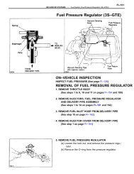
MFI AND SFI SYSTEMS–<strong>Fuel</strong> System (<strong>Fuel</strong> <strong>Pump</strong> (<strong>3S–GTE</strong>))FI–137(c) Remove the union bolt and two gaskets, and dis–connect the fuel inlet hose from the delivery pipe.HINT:• Put a suitable container or shop towel under thecoldstart injector pipe.• Slowly loosen the union bolt.(d) Install the fuel inlet hose and SST (pressure gauge)to the delivery pipe with three new gaskets and SST(union bolt).SST 09268–45012Torque: 29 N–m (300 kgf–cm, 22 ft–lbf)(e) Wipe off any splattered gasoline.(f) Using SST, connect terminals +B and FP of thedata link connector 1.SST 09843–18020(g) Reconnect the battery negative (–) cable.(h) Turn the ignition switch ON.(i) Measure the fuel pressure.<strong>Fuel</strong> pressure: 226 – 265 kPa(2.3 – 2.7 kgf/cm 2 , 33 – 38 psi)If pressure is high, replace the fuel pressure regulator.If pressure is low, check the following parts:• <strong>Fuel</strong> hoses and connection• <strong>Fuel</strong> pump• <strong>Fuel</strong> filter• <strong>Fuel</strong> pressure regulator(j) Remove SST.SST 09843–18020
FI–140MFI AND SFI SYSTEMS–<strong>Fuel</strong> System (<strong>Fuel</strong> <strong>Pump</strong> (<strong>3S–GTE</strong>))1. DISCONNECT CABLE FROM NEGATIVE TERMINALOF BATTERYCAUTION: Work must be started after approx. 20 se–conds or longer from the time the ignition switch isturned to the ”LOCK” position and the negative (–) ter–minal cable is disconnected from the battery.2. REMOVE FLOOR SERVICE HOLE COVER(a) Remove the lead wire protector.(b) Disconnect the fuel pump and fuel sender gaugeconnectors.(c) Remove the three screws and service hole cover.3. DRAW OUT FUEL FROM FUEL TANK(a) Remove the five screws and fuel sender gauge.(b) Remove the gasket from the fuel sender gauge.(c) Draw out the fuel from the fuel tank.(d) Install a new gasket to the fuel sender gauge.(e) Insert the sender gauge into the fuel tank.(f) Reinstall the fuel sender gauge with the five screws.Torque: 1.5 N–m (15 kgf–cm, 73 in.–lbf)4. REMOVE LH REAR WHEEL
MFI AND SFI SYSTEMS–<strong>Fuel</strong> System (<strong>Fuel</strong> <strong>Pump</strong> (<strong>3S–GTE</strong>))FI–1415. REMOVE FUEL TANK PROTECTORRemove the clip, six bolts and tank protector.6. REMOVE FUEL INLET PIPE PROTECTORRemove the two screws and pipe protector.7. DISCONNECT FUEL INLET PIPE FROM FUEL TANK(a) Remove the seven bolts, and disconnect the inletpipe.(b) Remove the gasket from the inlet pipe.8. DISCONNECT FUEL HOSESCAUTION: Remove the fuel filter cap to prevent thefuel from flowing out.(a) <strong>Fuel</strong> outlet hose(b) <strong>Fuel</strong> return hose(c) <strong>Fuel</strong> evaporation bent hose9. REMOVE FUEL TANK(a) Support the fuel tank with a jack.(b) Remove the nut, clip, pin and fuel tank bands. Re–move the two tank bands.(c) Remove the fuel tank.
MFI AND SFI SYSTEMS–<strong>Fuel</strong> System (<strong>Fuel</strong> <strong>Pump</strong> (<strong>3S–GTE</strong>))FI–143DISASSEMBLY OF FUEL PUMP(See page FI–142)1. REMOVE FUEL PUMP FROM FUEL PUMP BRACKET(a) Pull out the lower side of the fuel pump from thepump bracket.(b) Remove the rubber cushion from the fuel pump.(c) Remove the nut and spring washer, and disconnectthe lead wire from the fuel pump. Disconnect thethree lead wires.(d) Disconnect the fuel hose from the fuel pump, andremove the fuel pump.2. REMOVE FUEL PUMP FILTER FROM FUEL PUMP(a) Using a small screwdriver, remove the clip.(b) Pull out the pump filter.ASSEMBLY OF FUEL PUMP(See page FI–142)1. INSTALL FUEL PUMP FILTER TO FUEL PUMPinstall the pump filter with a new clip.2. INSTALL FUEL PUMP TO FUEL PUMP BRACKET(a) Connect the fuel hose to the outlet port of the fuelpump.(b) Connect the lead wire to the fuel pump with thespring washer and nut. Connect the two lead wires.(c) Install the rubber cushion to the fuel pump.(d) Install the fuel pump by pushing the lower side ofthe fuel pump.
FI–144MFI AND SFI SYSTEMS–<strong>Fuel</strong> System (<strong>Fuel</strong> <strong>Pump</strong> (<strong>3S–GTE</strong>))INSTALLATION OF FUEL PUMP(See page FI–139)1. INSTALL FUEL PUMP BRACKET ASSEMBLY TO FUELTANK(a) Install a new gasket to the pump bracket.(b) Insert the pump bracket assembly into the fuel tank.(c) Install the pump bracket with the six bolts.Torque: 2.9 N–m (30 kgf–cm, 26 in.lbf)2. INSTALL FUEL EVAPORATION BENT TUBE(a) Install a new gasket to the bent tube.(b) Install the bent tube with the four screws.Torque: 1.5 N–m (15 kgf–cm, 13 in.–lbf)(c) Install the bolt holding the bent tube to the fuelpump bracket.Torque: 2.9 N–m (30 kgf–cm, 26 in.–lbf)3. INSTALL FUEL TANK(a) Attach the fuel tank to the body.(b) Install the fuel tank band with the pin, clip and nut.Install the two tank bands.Torque: 22 N–m (220 kgf–cm, 16 ft–lbf)4. CONNECT FUEL HOSES(a) <strong>Fuel</strong> outlet hoseTorque (See page FI–9):30 N–m (310 kgf–cm, 22 ft–lbf)(b) <strong>Fuel</strong> return hose(c) <strong>Fuel</strong> evaporation bent hose
MFI AND SFI SYSTEMS–<strong>Fuel</strong> System (<strong>Fuel</strong> <strong>Pump</strong> (<strong>3S–GTE</strong>))FI–1455. INSTALL FUEL INLET PIPE(a) Install a new gasket to the inlet pipe.(b) Install the inlet pipe with the seven bolts.Torque: 2.9 N–m (30 kgf–cm, 26 in–lbf)6. INSTALL FUEL INLET PIPE PROTECTOR(a) Attach the pipe protector to the body.(b) Install the pipe protector with the two screws.7. INSTALL FUEL TANK PROTECTOR(a) Attach the tank protector to the body.(b) Install the tank protector with the clip and six bolts.8. INSTALL LH REAR WHEEL9. INSTALL FLOOR SERVICE HOLE COVER(a) Run the lead wires of the fuel pump and sendergauge through the holes in the service hole cover.(b) Install the service hole cover with the three screws.(c) Install the lead wire protector.10. FILL WITH FUEL11. CHECK FOR FUEL LEAKAGE (See page FI–10)12. CONNECT CABLE TO NEGATIVE TERMINAL OFBATTERY


