Troubleshooting Guide - weller truck parts
Troubleshooting Guide - weller truck parts
Troubleshooting Guide - weller truck parts

You also want an ePaper? Increase the reach of your titles
YUMPU automatically turns print PDFs into web optimized ePapers that Google loves.
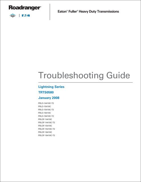
Eaton ® Fuller ® Heavy Duty Transmissions<br />
<strong>Troubleshooting</strong> <strong>Guide</strong><br />
Lightning Series<br />
TRTS0580<br />
January 2008<br />
FRLO-14410C-T2<br />
FRLO-15410C<br />
FRLO-15410C-T2<br />
FRLO-16410C<br />
FRLO-16410C-T2<br />
FRLOF-14410C<br />
FRLOF-14410C-T2<br />
FRLOF-15410C<br />
FRLOF-15410C-T2<br />
FRLOF-16410C<br />
FRLOF-16410C-T2
General Warnings<br />
Before starting a vehicle:<br />
1. Sit in driver’s seat<br />
2. Place shift lever in neutral<br />
3. Set the parking brake<br />
Before working on a vehicle or leaving the cab with engine running:<br />
1. Place shift lever in neutral<br />
2. Set parking brake<br />
3. Block wheels<br />
Do not release the parking brake or attempt to select a gear until<br />
the air pressure is at the correct level.<br />
When parking the vehicle or leaving the cab:<br />
1. Place shift lever in neutral<br />
2. Set the parking brake<br />
Do not operate if alternator lamp is lit or if gauges indicate low<br />
voltage.<br />
General Warnings<br />
Suggested Tools<br />
• Volt/Ohm Meter<br />
SPX / Kent-Moore 1 (800) 328-6657<br />
P/N 5505027<br />
• PC-based Service Tool “ServiceRanger”<br />
Contact your OEM<br />
• Data Link Tester<br />
Eaton Service Parts 1 (800) 826-4357<br />
P/N MF-KIT-04<br />
• Eaton Test Adapter Kit<br />
SPX / Kent-Moore 1 (800) 328-6657<br />
P/N J-43318<br />
• 6-Pin Deutsch Diagnostic Adapter<br />
SPX / Kent-Moore 1 (800) 328-6657<br />
P/N J-38500-60A<br />
Related Publications<br />
• TRIG-0580 - Lightning Installation <strong>Guide</strong><br />
• TRDR-0580 - Lightning Driver Instructions<br />
• TRSM-0580 - Lightning Service Manual<br />
For more information call 1-800-826-HELP (4357) or visit<br />
www.Roadranger.com.
Section 1: Basic <strong>Troubleshooting</strong><br />
Diagnostic Procedure for Lightning Models .............1-2<br />
Operational Check List .............................................1-3<br />
Basic System <strong>Troubleshooting</strong> .................................1-4<br />
What To Do If The Transmission<br />
Is Not Operating Properly ................................1-5<br />
Retrieving Fault Information .....................................1-6<br />
Fault Code Table for Lightning Transmission ...........1-7<br />
Symptom Complaints ...............................................1-8<br />
Air System <strong>Troubleshooting</strong><br />
Vehicle Air Supply Requirement .............................1-12<br />
Air System - Overview ............................................1-13<br />
Air System - ECU ...................................................1-14<br />
Air System - Splitter Subsystem ............................1-15<br />
Air System - Range Subsystem ..............................1-16<br />
Clutch Housing Breather Leak Overview ................1-18<br />
Clutch Housing Breather Leak ................................1-19<br />
Transmission ECU Breather Leak Overview ............1-20<br />
Transmission ECU Breather Leak ...........................1-21<br />
Range Cylinder Test Overview ................................1-22<br />
Range Cylinder Test ...............................................1-23<br />
Splitter Cylinder Test Overview ..............................1-26<br />
Splitter Cylinder Test ..............................................1-27<br />
Electronic System <strong>Troubleshooting</strong><br />
Electrical System Requirements .............................1-30<br />
Wiring Diagram ......................................................1-31<br />
Pinouts ...................................................................1-32<br />
Power-Up Sequence Test Overview .......................1-34<br />
Power-up Sequence Test .......................................1-35<br />
Electrical Pretest Overview .....................................1-38<br />
Electrical Pretest ....................................................1-39<br />
Shift Knob Test- No Fault Codes Overview .............1-42<br />
Shift Knob Test- No Fault Codes ............................1-43<br />
J-1587 Data Link Test Overview .............................1-46<br />
J-1587 Data Link Test ............................................1-47<br />
Table of Contents<br />
Section 2: Fault Isolation Procedures<br />
Component Code 11(SID 254, FMI 12)<br />
Transmission ECU ............................................ 2-1<br />
Component Code 33 (PID 158 or 168, FMI 3 or 4)<br />
System Voltage Fault ........................................ 2-3<br />
Component Code 35 (SID 231, FMI 2)<br />
J-1939 Data Link Test ...................................... 2-5<br />
Component Code 36 (SID 48 or 49, FMI 2)<br />
Position Sensor Test ...................................... 2-13<br />
Component Code 43 (SID 36, FMI 4, 5, 6)<br />
Low Range Solenoid ...................................... 2-15<br />
Component Code 46 (SID 37, FMI 4, 5, 6)<br />
Splitter Solenoid ............................................. 2-17<br />
Component Code 48 (SID 35, FMI 4, 5, 6)<br />
High Range Solenoid ...................................... 2-19<br />
Component Code 58 (PID 191, FMI 2)<br />
Output Shaft Speed Sensor ............................ 2-21<br />
System Code 66 (SID 58, FMI 1)<br />
Unconfirmed Torque Path .............................. 2-25<br />
System Code 71 (SID 61, FMI 7)<br />
Range or Splitter Stuck in Gear ...................... 2-29<br />
Component Code 73 (SID 58, FMI 11)<br />
Transmission Missed Synchronous ............... 2-31<br />
System Code 74 (SID 14, FMI 7)<br />
Engine Missed Synchronous .......................... 2-33<br />
System Code 93 (SID 231, FMI 14)<br />
J-1939 Engine Message Fault ......................... 2-33<br />
Reverse Switch Test Overview ............................... 2-39<br />
Reverse Switch Test .............................................. 2-40<br />
Neutral Switch Test Overview ................................ 2-43<br />
Neutral Switch Test ................................................ 2-44<br />
1-1<br />
Table of Contents
Diagnostic Procedure for Lightning Models<br />
1-2<br />
Key On<br />
Service light<br />
comes on for a<br />
few seconds<br />
then turns off<br />
Yes<br />
Retrieve active<br />
fault codes<br />
Active Codes?<br />
Retrieve inactive<br />
fault codes<br />
Inactive<br />
Codes?<br />
Symptom?<br />
No<br />
(Code 25)<br />
No<br />
(Code 25)<br />
No<br />
Test Complete<br />
Fault Isolation Procedures<br />
No<br />
Yes<br />
Yes<br />
Yes<br />
- Perform vehicle electrical test<br />
- Perform "No service light test"<br />
- Solid service light? - Replace ECU<br />
- Perform vehicle electrical test<br />
- Follow troubleshooting guide<br />
diagnostics for all Actives Codes<br />
- Clear Inactive Codes/test drive &<br />
confirm code(s) have not reset<br />
- Record & clear inactive fault codes<br />
- Verify complaints / test drive<br />
- If fault code is reset after clearing,<br />
perform vehicle electrical test, and<br />
following diagnostics for symptom<br />
driven faults<br />
- Perform vehicle electrical test<br />
- Perform pneumatic test<br />
- Isolate transmission / clutch issues<br />
- Follow basic troubleshooting/symptom<br />
driven diagnostic procedures
Operational Check List<br />
Fault Isolation Procedures<br />
When operating properly, the lightning transmission will act in the following manner:<br />
Top-2 feature will not function with cruise control turned off.<br />
Service light flashes once at vehicle initial power up.<br />
Service light flickers at vehicle power down.<br />
Service light flashes continuously with an active fault code.<br />
Synchronizer will not trigger with key off.<br />
Synchronizer will not trigger in neutral with key on and vehicle stationary.<br />
Synchronizer will trigger with key on, vehicle stationary and lever moved into a high range gear.<br />
Synchronizer will not downshift into low range if lever is moved into a low range gear at too high of road speed.<br />
If started in a high range gear the vehicle accelerator pedal will be “dead”.<br />
If driver beats the range up-shift with lever movement to a high range gear the accelerator pedal is “dead” until synchronous<br />
is made.<br />
Splitter will not trigger with key off.<br />
Splitter will trigger with key on and in any lever position.<br />
Accelerator pedal is “dead” when splitter is up shifting if the driver attempts to accelerate before splitter synchronous is<br />
made.<br />
Engine accelerates when splitter downshifts if the driver doesn’t control engine RPM for proper synchronous.<br />
Aggressive splitter shifts below 1100 engine RPMs and whenever the transmission has a fast deceleration of the output<br />
shaft.<br />
Aggressive splitter shifts with clutch disengaged or foot resting on clutch pedal disengaging clutch switch.<br />
Aggressive splitter shifts with clutch switch wired improperly – check for engine brake and cruise control functionality.<br />
1-3<br />
Fault Isolation Procedures
Basic System <strong>Troubleshooting</strong><br />
1-4<br />
Fault Isolation Procedures<br />
Following is information to help a vehicle operator start basic troubleshooting of the transmission system.This is not a complete<br />
list. In many cases, the vehicle needs to be evaluated by a trained and experienced transmission technician.<br />
Problem Possible Causes<br />
Growl/Rattle in a “float” or<br />
coast condition.<br />
Check for damaged, worn, or defective driveshaft, support bearing, or u-joints, which would result<br />
in noise or vibration. Check for improper vehicle ride height, which would cause improper u-joint<br />
operating angles. Check for axle problem, which would result in noise or vibration. Check for tire<br />
problem, which would result in noise or vibration.<br />
At idle Check for damaged or defective master clutch, master clutch release bearing, or clutch linkage,<br />
which would result in noise or vibration. Check for loose components, brackets, exhaust system,<br />
and hoses in transmission area, which would result in noise or vibration.<br />
Growl/Rattle on a “pull” Check for engine problem, which would result in noise or excessive vibration.Check master clutch<br />
for defects in dampening devices.<br />
Lever Check for loose or damaged shift lever, which may vibrate and cause noise. Check for components<br />
added to the shift lever; such as, cruise control, which may vibrate and cause noise.<br />
All other conditions Check for loose clutch housing bolts. Check transmission oil for excessive metal particles, which<br />
may indicate internal problem. Check for damaged or worn gearing.<br />
Problem Possible Causes<br />
Hard Lever Shifting Check for damaged or binding shift lever or shift control system.Check for lever interference with<br />
cab floor. Check for upper or lower shift boot tugging on shift lever. Check for a defective or damaged<br />
master clutch, which would result in clutch drag. Check for improper clutch brake engagement.<br />
Check that proper shifting procedures are followed.<br />
Problem Possible Cause<br />
Transmission is operating<br />
at higher than normal temperature<br />
If transmission is equipped with an internal cooler, check for pinched engine coolant hoses or<br />
closed shut off valves. See section on Operating Temperatures with Coolers. Check oil level.
Fault Isolation Procedures<br />
What to Do if the Transmission is Not Operating Properly<br />
If a problem occurs with the transmission or vehicle system, the transmission may not shift correctly. These effects may include:<br />
Harsh, slow, or grinding button only shifts.<br />
No button shifts (5 gear ratios only).<br />
No range shift (low range or high range gear ratios only).<br />
The Service Light on the Shift Knob may be on continuously, may be flashing, or may not illuminate at all.<br />
If the Transmission is Not Operating Properly, Try the Following Steps:<br />
1. Check the dash air gauge to make sure at least 90 PSI is available in both primary and secondary air systems.<br />
2. Try resetting the Transmission Electronic Control Unit (ECU) - See procedure below.<br />
3. If vehicle and road conditions permit, you may be able to operate the transmission as a 5 speed (no button shifts).<br />
Transmission Reset Procedure<br />
In some cases, “resetting” the transmission Electronic Control Unit (ECU) can restore proper transmission operation. Use the following<br />
procedure to reset the ECU.<br />
When it is safe to do so, stop the vehicle.<br />
Place the transmission shift lever in neutral and turn the ignition key to the “off” position.<br />
Wait 5 seconds.<br />
Restart the engine.<br />
If the problem continues, proceed to page 9 and identify the symptom.<br />
Transmission Diagnostics<br />
The Lightning Series Transmission ECU has self-diagnostic capability. The transmission recognizes when a problem occurs and<br />
“stores” the information about these problems (faults) in the ECU memory. This information can be retrieved by the following<br />
methods:<br />
Retrieve basic fault information (flash codes) by counting flashes of the service light.<br />
Some OEM vehicles have an electronic dashboard, which displays fault information. Refer to the specific OEM chassis<br />
operator instructions for the procedure.<br />
Connect an applicable hand-held or PC diagnostic tool to the vehicle’s SAE J-1587 diagnostic connector.<br />
1-5<br />
Fault Isolation Procedures
Retrieving Fault Information<br />
The transmission Electronic Control Unit (ECU) turns on the<br />
service lamp, located on the shift knob, in the event the ECU<br />
detects an electronic fault and at initial power-up. Once the<br />
ECU has successfully powered-up, the ECU turns off the service<br />
lamp. The power-up sequence usually takes a few seconds.<br />
The service lamp remains on continuously if the ECU<br />
execution malfunctioned at power-up. The ECU begins code diagnostics<br />
only after the ECU has successfully powered-up. The<br />
service lamp flashes steadily if the ECU has detected an Active<br />
fault code.<br />
Note: Any Active code detected at vehicle start-up immediately<br />
starts flashing the service light on the shift knob.<br />
The service light provides access to diagnostic fault information,<br />
which has been logged in the transmission ECU. The service<br />
light flashes a sequence of on/off pulses, which can be<br />
translated into specific “flash codes”. The flash codes can then<br />
be used to identify a specific fault in the transmission system.<br />
Transmission faults are classified as either Active (current<br />
problem) or In-Active (non-current problem). An Active fault is<br />
logged when the ECU recognizes a problem with the transmission.<br />
During an Active fault, the service light flashes steadily or<br />
may stay on continuously. If during vehicle operation, the<br />
problem corrects itself, the service light stops flashing and the<br />
fault is logged as an In-Active fault.<br />
How to Retrieve Fault Codes<br />
Retrieve Lightning fault codes by enabling the Lightning system’s<br />
self-diagnostic mode.<br />
Note: You can also use a P.C. based diagnostic tool such as<br />
ServiceRanger to retrieve fault codes.<br />
Retrieving Active Fault Codes:<br />
1. Place the shift lever in neutral.<br />
2. Set the parking brakes.<br />
3. Turn the ignition key on but do not start the engine.<br />
4. Starting with the key in the on position. Turn the key<br />
off and on two (2) times within five seconds ending<br />
with the key in the on position.<br />
5. Observe the flash sequence of the service light on the<br />
shift knob. Flash codes may take 5 seconds to begin<br />
flashing. A one or two second pause separates each<br />
stored code, and the sequence automatically repeats<br />
itself after flashing all codes.<br />
1-6<br />
Fault Isolation Procedures<br />
Retrieving In-Active Fault Codes:<br />
1. Use the procedure to retrieve Active fault codes except,<br />
turn the key off and on four (4) times within five<br />
seconds ending with the key in the on position.<br />
2. Observe the flash sequence of the service light on the<br />
shift knob. A one or two second pause separates each<br />
stored code, and the sequence automatically repeats<br />
itself after flashing all codes.<br />
Clearing Fault Codes:<br />
The following procedure clears all In-Active fault codes from<br />
the ECU’s memory.<br />
1. Place the shift lever in neutral.<br />
2. Set the parking brakes.<br />
3. Turn the ignition key on but do not start the engine.<br />
4. Start with the key in the on position. Turn the key off<br />
and on six (6) times within five seconds ending with<br />
the key in the on position. The service light will flash<br />
on for 5 seconds confirming the codes are cleared.<br />
Example of Flash Codes<br />
Fault Code 35 Fault Code 11<br />
Short Pause Long Pause Short Pause<br />
Service Light
Fault Isolation Procedures<br />
Fault Code Table for Lightning Transmission<br />
Component Fault Codes*<br />
Flash<br />
Code<br />
*Component Fault Codes specifically isolate problems that may arise with the electronic components used in the Lightning series<br />
transmissions. These codes occur at initial vehicle power-up if not induced by intermittent vibration or heat problems.<br />
**System Fault Codes specifically isolate problems that may arise from a mechanical or pneumatic problem that has prevented<br />
or missed a shift in the Lightning transmission. System fault codes are only active during vehicle operation and are not detected<br />
at initial vehicle power-up.<br />
Note: System fault codes also indicate problems with other components that affect the performance of the transmission such as<br />
low air pressure. Troubleshoot the code properly to isolate the component causing the fault to become active.<br />
# Hand Held Codes<br />
Description MID PID SID FMI<br />
11 Transmission ECU 130 254 12<br />
25 No Codes 130<br />
33 Ignition/Battery Voltage Low or High 130 158 or 168 3 or 4<br />
35 Engine to Transmission J1939<br />
Communication Link<br />
130 231 2<br />
36 Shift Lever Position Sensor 130 48 or 49 2<br />
43 Low Range Shift Solenoid 130 36 4, 5, or 6<br />
46 Splitter Shift Solenoid 130 37 4, 5, or 6<br />
48 High Range Shift Solenoid 130 35 4, 5, or 6<br />
58 Output Speed Sensor 130 191 2<br />
System Fault Codes **<br />
Flash Code Description MID PID SID FMI<br />
66 Unconfirmed Torque Path (Input speed and<br />
output speed do not equal known gear ratio)<br />
130 58 1<br />
71 Splitter or Range Stuck in Gear 130 61 7<br />
73 Transmission Missed Synchronization 130 58 11<br />
74 Engine/Transmission Missed<br />
Synchronization<br />
130 14 7<br />
93 J-1939 Engine Message Fault 130 231 14<br />
MID – Message ID Assignment. In this case, MID 130 represents the transmission.<br />
PID – Parameter ID Assignment. Generally represents a status or value.<br />
SID – Subsystem ID Assignment. Identifies a failure in a subsystem.<br />
FMI – Failure Mode ID. Describes the type of failure detected in the subsystem<br />
1-7<br />
Fault Isolation Procedures
Symptom Complaints<br />
1-8<br />
Fault Isolation Procedures<br />
Symptom Possible Condition Remedy Reference<br />
No service light Electrical circuit is open,<br />
grounded, or blown VIGN fuse<br />
or faulty light<br />
Service light on continuously Light circuit grounded to VBATT,<br />
transmission performance not<br />
affected<br />
Transmission ECU internal failure;<br />
3 speed operation only;<br />
No splitter or range shifts<br />
No fault codes set. Performance of<br />
transmission not affected by nonfunctioning<br />
light. Check fuse then if<br />
necessary, perform service light<br />
test.<br />
Repair vehicle wiring harness.<br />
Perform vehicle electrical test, if OK<br />
- replace transmission ECU.<br />
Top 2 option not functioning Cruise control turned off Turn on cruise control.<br />
No button shifts after cruise control<br />
if turned off while in Top 2<br />
mode<br />
Top 2 option stops functioning<br />
as a result of another problem<br />
Repair for other faults such as Output<br />
Speed Sensor Position Sensor.<br />
Look for other complaints such as<br />
engine brake or cruise not functioning.<br />
Hold Mode Normal Operation. Lever must be<br />
cycled through neutral to regain button<br />
function.<br />
Harsh or aggressive splitter shifts ECU Malfunction Active Fault Code 11. page 1<br />
Before proceeding, see note at<br />
bottom of page.<br />
Position Sensor Malfunction Active Fault Code 36. page 13<br />
(any shift using the splitter button) Engine Missed Synchronization Active Fault Code 74. page 33<br />
Grinding or Raking Splitter Shifts Out-Of-Synchronous or shifts<br />
Engine Synchronous speed outof-limit<br />
of operating range<br />
(Shifts from 1st to 2nd, 3rd. to 4<br />
th, 5th to 6th, 7 th to 8 th, and 9 th<br />
to 10th. Shift grinds but engages.)<br />
Lever/Splitter shifts attempted in an<br />
out-of-synchronous condition. Review<br />
Driver Instruction Book -<br />
TRDR-0580 - for proper driving<br />
techniques.<br />
Low or high air pressure Faulty Air Regulator.<br />
Splitter leak or partial blocked air<br />
system<br />
Driver resting foot on Clutch<br />
Pedal so as to disengage clutch<br />
switch but still has clutch engaged<br />
Perform Splitter Cylinder Test. page 26<br />
Remove foot from clutch pedal except<br />
when necessary to shift, start or<br />
stop the vehicle.
Fault Isolation Procedures<br />
Symptom Possible Condition Remedy Reference<br />
Clutch Switch Contamination<br />
built up on switch, for example,<br />
dirt, ice, etc. or Mechanical<br />
Clutch Linkage<br />
Note: Aggressive splitter shifts may occur normally under the following conditions.<br />
Cruise control and engine brake is<br />
also inoperative when the clutch<br />
switch malfunctions. Refer to OEM<br />
manual for troubleshooting clutch<br />
switch.<br />
1. Low speed splitter shifts below 1100 RPMs. - This is normal operation.<br />
2. Splitter shifts on grades with heavily loaded vehicle. - This is normal operation.<br />
3. Anytime the vehicle has a fast deceleration of the transmission output shaft. For example, making a hard left-hand turn<br />
and moving the splitter at the same time. - This is normal operation.<br />
Symptom Possible Condition Remedy Reference<br />
Harsh shifts (Lever Only) Out-Of-Synchronous Shifts Lever shifts attempted in an out-ofsynchronous<br />
condition. Review Driver’s<br />
Instruction Book for proper techniques.<br />
(Skip shifts. i.e. 1 st to 3 rd., or 3<br />
rd. to 5 th.)<br />
Clutch Drag Adjust Clutch and check for clutch<br />
slippage and drag.<br />
Clutch Brake Check for improper clutch brake engagement.<br />
Slow/grinding/raking or inoperative<br />
Range Shift (Shift from 6 th to<br />
7 th or from 7 th to 6 th.)<br />
Low or High Air Pressure<br />
Air System Leaks<br />
Reduced Air Flow<br />
Damaged Mechanical <strong>parts</strong> internal<br />
to the transmission<br />
Perform Range Cylinder Test. page 22<br />
Five speed transmission. (Only<br />
Even or Odd Numbered Gears.)<br />
ECU Malfunction Active Fault Code 11. page 1<br />
Unconfirmed torque path Active Fault Code 66. page 25<br />
through transmission<br />
Splitter stuck in gear Active Fault Code 71. page 29<br />
Review Air System Overview.<br />
Repair for damaged internal <strong>parts</strong>.<br />
page 13<br />
Output Speed Sensor Malfunc- Perform Output Shaft Speed Sensor page 21<br />
tion<br />
test.<br />
Splitter System Air Leak Perform Splitter Cylinder test. page 26<br />
Shift Knob Malfunction No Active Fault Codes. Perform Shift<br />
Knob test.<br />
page 42<br />
1-9<br />
Fault Isolation Procedures
Six speed transmission. (Only 1st<br />
through 6th gears.)<br />
1-10<br />
Fault Isolation Procedures<br />
Symptom Possible Condition Remedy Reference<br />
Four Speed Transmission. (Only 7<br />
th through 10 th gears.)<br />
Three Speed Transmission (Only<br />
1 st, 3 rd., 5 th gears)<br />
Splitter Solenoid Short or Open Active Fault Code 46. Perform Solenoid<br />
test.<br />
Loss of communication with<br />
engine<br />
Active Fault Code 35 and gears 1, 3, 5,<br />
7, 9. J-1939 communication link broken.<br />
page 17<br />
page 5<br />
Range system air leak Perform Range Cylinder test. page 22<br />
Position sensor malfunction Active Fault Code 36. page 13<br />
Low Range Solenoid Malfunction<br />
Active Fault Code 43. page 15<br />
High Range Solenoid Malfunction<br />
Active Fault Code 48. page 19<br />
Range stuck in gear. Active Fault Code 71. page 29<br />
Transmission missed synchronous.<br />
Active Fault Code 73. page 31<br />
High Range Synchronizer Mechanical<br />
Failure<br />
Low Range Solenoid Malfunction<br />
Perform Range Cylinder test prior to<br />
disassembly, then replace damaged<br />
synchronizer <strong>parts</strong> if required. Refer<br />
to “Synchronizer” repair strategy item<br />
TRSM-0915 (Note: after 12/31/04 this<br />
publication will be TRMT-0001) for<br />
repair details.<br />
page 22<br />
Active Fault Code 43. page 15<br />
Range System Air Leak Perform Range Cylinder test. page 22<br />
High Range Solenoid Malfunction<br />
Active Fault Code 48. page 19<br />
Range stuck in gear. Active Fault Code 71. page 29<br />
Low Range Synchronizer Mechanical<br />
Failure<br />
Perform air system test prior to disassembly,<br />
then replace damaged synchronizer<br />
<strong>parts</strong> if required. Refer to<br />
“Synchronizer” repair strategy item<br />
TRSM-0915 (Note: after 12/31/04 this<br />
publication will be TRMT-0001) for<br />
repair details.<br />
Low System Voltage Active Fault Code 33. page 3<br />
Loss of air pressure to transmission.<br />
Check vehicle air pressure.<br />
ECU Malfunction. Active Fault Code 11.<br />
Service light on continuously. Replace<br />
ECU.<br />
page 1
Fault Isolation Procedures<br />
Symptom Possible Condition Remedy Reference<br />
Two Speed Transmission (only 7<br />
th, 9 th gears)<br />
Software download unsuccessful<br />
ECU malfunction service light<br />
on continuously<br />
Neutral Switch Wheel Chair Lift / PTO etc. not<br />
operating<br />
Engine will not crank (some applications)<br />
Reverse Switch Reverse Light / Beeper not<br />
functioning.<br />
Replace ECU.<br />
Replace ECU.<br />
Perform Neutral Switch Test per OEM<br />
recommendations.<br />
Perform Neutral Switch Test per OEM<br />
recommendations.<br />
Perform Reverse Switch Test per<br />
OEM recommendations.<br />
1-11<br />
Fault Isolation Procedures
Vehicle Air Supply Requirement<br />
1-12<br />
Fault Isolation Procedures<br />
The transmission filter/regulator assembly provides the inlet port for transmission supplied air. You will find the filter/regulator<br />
located at the rear of the transmission on the driver’s side of the <strong>truck</strong>. The filter/regulator assembly regulates the transmission<br />
supply to 80 PSI (551 kPa) maximum.<br />
Filter / Regulator<br />
Inlet Air Pressure Required 90-130 PSI (620-896 kPa)<br />
Air Dryer Required<br />
Inlet Port Size SAE 3/8” – 18 NPT
Air System - Overview<br />
Fault Isolation Procedures<br />
The Lightning series transmission uses an automatically controlled range cylinder to manage the air operated range shift between<br />
6th and 7th gear. The button on the shift knob controls the splitter shift. Splitter shifts occur every time the transmission shifts<br />
consecutive from one gear to the next gear or when the button is moved from one state to the next.<br />
The simple block diagram below shows the relationship between the air system and electronic controls.<br />
Splitter Signal from Shift Knob<br />
Engine Communication (J1939)<br />
Diagnostic Communication (J1587)<br />
H<br />
L Non-Contacting Sensor to<br />
sense desired range position<br />
Splitter<br />
Range<br />
Constant Air<br />
H L S<br />
Charge Air<br />
The Lightning series transmission utilizes an electric over air concept for actuating the splitter and range cylinders. An electric<br />
signal is sent to the ECU. The ECU then, enables a solenoid valve, which in turn directs air to the appropriate cylinder. A switch in<br />
the shift knob directs the splitter shift. The position of the switch indicates to the ECU the desired splitter state. The ECU makes<br />
the shift automatically when the proper conditions are achieved. The signal to the ECU for a range shift is automatically made when<br />
the shift lever passes from the middle rail (6th gear) to the outside rail (7th gear). A sensor detects the movement and signals the<br />
ECU to actuate the range valve. As with the splitter shift, the range shift only occurs when a specific set of conditions is achieved.<br />
ECU<br />
Solenoid<br />
Pak<br />
Output Speed<br />
Sensor<br />
1-13<br />
Fault Isolation Procedures
Air System - ECU<br />
1-14<br />
Fault Isolation Procedures<br />
The transmission’s electronic control unit (ECU) activates solenoids in the ECU, which opens up internal air passages. The transmission<br />
air filter/regulator is the only external air system component.<br />
The air moves through passages internal to the transmission and the seal plate of the ECU. The illustration below shows the air<br />
passages as viewed through the ECU.<br />
Splitter<br />
80 PSI Supply<br />
from Regulator /<br />
Constant Air<br />
to Splitter<br />
To Splitter<br />
Cylinder<br />
Range Cylinder<br />
O-ring<br />
Seal Plate<br />
Splitter Diagnostic Port<br />
Supply to Valves<br />
Range HI<br />
Diagnostic Port<br />
To HI Range<br />
Range HI Range Valve<br />
Supply to<br />
Valves<br />
Splitter Cylinder<br />
O-rings<br />
Exploded View of Air System<br />
From Splitter Valve<br />
To LO Range<br />
Electronic Control Unit<br />
(ECU)<br />
LO Range Valve<br />
Splitter Valve
Air System - Splitter Subsystem<br />
Fault Isolation Procedures<br />
The ECU controls the operation of the splitter solenoid function, responding to driver input from the splitter button on the shift<br />
knob or Top-2 operation.<br />
The splitter cylinder has three distinct positions, forward (overdrive), rear (direct) and intermediate (neutral). The forward position<br />
is achieved by activating the splitter solenoid valve, which applies air pressure to the rearward side of the piston. This is the splitter<br />
state for the even numbered gears (2, 4, 6, 8 and 10)<br />
The rearward position is achieved by de-activating the splitter solenoid valve, which exhausts the air pressure from the rearward<br />
side of the splitter piston. The constant air pressure then forces the piston rearward. This is the splitter state for the odd numbered<br />
gears (1, 3, 5, 7 and 9).<br />
The intermediate or neutral state is achieved by the ECU rapidly turning on and off the splitter solenoid valve. This condition results<br />
in a pressure on the rearward side of the splitter piston that is between 0 and full system pressure. This neutral state is used to<br />
allow the gears to synchronize prior to engagement, thereby significantly improving the shift quality.<br />
Constant Air Pressure Constant Air Pressure<br />
Splitter in<br />
Direct<br />
Constant Air Pressure<br />
Signal Air Pressure<br />
Splitter in<br />
Overdrive<br />
Signal Air Pressure<br />
Splitter in<br />
Neutral<br />
1-15<br />
Fault Isolation Procedures
Air System - Range Subsystem<br />
1-16<br />
Fault Isolation Procedures<br />
The ECU controls the operation of all range solenoid valve functions. The driver’s movement of the shift lever accomplishes a<br />
change in the position of the range from high range to low range or vice versa.<br />
The range piston has two distinct positions. Both the forward and rearward positions are a function of mechanical stops. Only one<br />
side of the piston has air pressure at any one time. The ECU automatically selects either high or low range as the lever passes<br />
through neutral when making an up-shift from 6th gear to 7th gear or the downshift from 7th gear to 6th gear.<br />
In either case, the distinct sound of the range shifting is audible outside the cab, standing next to the stationary <strong>truck</strong>.<br />
Air<br />
Pressure<br />
Low Range High Range<br />
LO<br />
R<br />
HI<br />
R<br />
2<br />
1<br />
4<br />
3<br />
6<br />
5<br />
Low Range<br />
8<br />
7<br />
10<br />
9<br />
High<br />
Range<br />
Air<br />
Pressure
Fault Isolation Procedures<br />
This page left blank intentionally.<br />
1-17<br />
Fault Isolation Procedures
Clutch Housing Breather Leak Overview<br />
Overview<br />
Air leaks out the breather located on top of clutch housing.<br />
An air operated PTO with an air leak can pressurize the<br />
transmission and cause air to leak out the transmission<br />
breather.<br />
Detection<br />
Audible Air Leak<br />
Fallback<br />
There is no fallback mode for this failure.<br />
1-18<br />
Fault Isolation Procedures<br />
Required Tools<br />
Basic Hand Tools<br />
Possible Causes<br />
Possible Leak Paths<br />
Splitter Cylinder O-Rings<br />
Range Cylinder O-Ring<br />
Air operated PTO leak<br />
Splitter Cylinder Range Cylinder
Clutch Housing Breather Leak<br />
Fault Isolation Procedures<br />
Step A Procedure Condition Action<br />
1. Key on.<br />
2. Vehicle stationary and secured,<br />
air system fully charged, engine<br />
not running.<br />
3. Listen for air leaking<br />
out the breather while<br />
moving the shift lever<br />
to make the range<br />
cylinder shift from low<br />
range to high range.<br />
When stationary, the<br />
lever must be moved<br />
in and out of a high<br />
range gear to make the<br />
synchronizer shift.<br />
Note: Oil leaking out the<br />
breather may be a sign<br />
indicating an air leak<br />
internal to the<br />
transmission.<br />
Air leaks in both positions Repair the splitter cylinder, and<br />
replace all cylinder o-rings. Go to<br />
Step V.<br />
Air leaks only in low<br />
range<br />
Repair the range cylinder, and<br />
replace all cylinder o-rings. Go to<br />
Step V.<br />
Step V Procedure Condition Action<br />
1. Fully charge air<br />
system on vehicle and<br />
check for<br />
effectiveness of repair.<br />
Breather still leaks Go to Step A.<br />
Breather does not leak Test Complete.<br />
1-19<br />
Clutch Housing Breather<br />
Leak
Transmission ECU Breather Leak<br />
Overview<br />
Overview<br />
Air leaks out the breather on the ECU.<br />
The breather exhausts a slight amount of air every time<br />
the transmission makes a range shift and when the splitter<br />
shifts to any odd numbered gear.<br />
Detection<br />
Audible Air Leak.<br />
Fallback<br />
There is no fallback mode for failure.<br />
1-20<br />
Possible Leak Paths<br />
Fault Isolation Procedures<br />
Required Tools<br />
Basic Hand Tools<br />
Possible Causes<br />
Solenoid<br />
(Non-Serviceable - Inside ECU)<br />
This fault can be caused by any of the following:<br />
Splitter or Range Cylinder O-rings<br />
Solenoid Seals or O-rings (ECU)<br />
Seal Plate<br />
Possible Leak Path<br />
Splitter Cylinder Range Cylinder
Transmission ECU Breather Leak<br />
Fault Isolation Procedures<br />
Step A Procedure Condition Action<br />
1. Key on, vehicle stationary and<br />
secured, air system fully<br />
charged, engine not running.<br />
2. Cycle the splitter<br />
cylinder by moving the<br />
button on the shift<br />
knob from the down<br />
position to the up<br />
position.<br />
Leak stops with the<br />
button in the up position.<br />
Leaks in either position Go to Step B.<br />
Replace the splitter cylinder orings<br />
and clean out any<br />
contamination in the cylinder. If leak<br />
continues after making this repair,<br />
then replace the transmission ECU<br />
and seal plate. Go to Step V.<br />
Step B Procedure Condition Action<br />
1. Key on, vehicle stationary and<br />
secured, air system fully<br />
charged, engine not running.<br />
2. Cycle the range<br />
cylinder by moving the<br />
shift lever into high<br />
range (the 7/8 gear<br />
position) then back into<br />
neutral. The<br />
synchronizer makes a<br />
distinct audible noise<br />
when shifting.<br />
Leak stops when in high<br />
range.<br />
Leak stops when in low<br />
range.<br />
Replace the range cylinder piston<br />
and clean out any contamination in<br />
the cylinder. If leak continues after<br />
making this repair, then replace the<br />
transmission ECU and seal plate.<br />
Go to Step V<br />
Replace the range cylinder piston<br />
and clean out any contamination in<br />
the cylinder. If leak continues after<br />
making this repair, then replace the<br />
transmission ECU and seal plate.<br />
Go to Step V.<br />
Step V Procedure Condition Action<br />
1. Charge the vehicle air<br />
system and test<br />
repairs for<br />
effectiveness.<br />
No Leaks Test Complete<br />
Air still leaks out breather<br />
on ECU.<br />
Repeat test procedures for air leaks.<br />
1-21<br />
Transmission ECU<br />
Breather Leak
Range Cylinder Test Overview<br />
Overview<br />
The range cylinder test does not relate to any specific fault<br />
code, but must be performed prior to disassembly of the<br />
transmission if a range system mechanical failure is suspected.<br />
The range cylinder test verifies the basic air system<br />
inputs are operating correctly, before proceeding with<br />
disassembly. The driver complaint must be confirmed or<br />
duplicated before preceding with the testing.<br />
Detection<br />
There is no detection process specifically for the Range<br />
Cylinder. However, failures of this type are generally detected<br />
by the driver as a symptom such as the transmission<br />
range shift may grind, rake, or fail to operate.<br />
Fallback<br />
There is no fallback for the Range Cylinder Test.<br />
1-22<br />
Fault Isolation Procedures<br />
Required Tools<br />
Basic Hand Tools<br />
Possible Causes<br />
This fault can be caused by any of the following:<br />
Truck air pressure out of range<br />
Faulty air/filter regulator<br />
Air system contamination<br />
Friction material worn or damaged on synchronizer<br />
Other internal mechanical failure
Range Cylinder Test<br />
Fault Isolation Procedures<br />
Step A Procedure Condition Action<br />
1. Start vehicle and<br />
build up air pressure<br />
to maximum. Shut off<br />
vehicle.<br />
Vehicle's primary and<br />
secondary air supply is<br />
less than 90 PSI or leaks<br />
down<br />
Vehicle air pressure is<br />
greater than 90 PSI and<br />
no leaks.<br />
Repair vehicle's air system and go<br />
to Step V.<br />
Go to Step B.<br />
Step B Procedure Condition Action<br />
1. Drain air tanks to prevent injury.<br />
2. Remove one of three plugs in<br />
transmission filter/regulator and<br />
insert pressure gauge.<br />
3. Start vehicle and build<br />
up air pressure to<br />
maximum. Shut off<br />
vehicle.<br />
Front of<br />
Transmission<br />
Filter / Regulator<br />
Regulated<br />
Air Pressure<br />
Air Inlet<br />
Port<br />
Transmission filter/<br />
regulator pressure less<br />
than or greater than 77 to<br />
82 PSI.<br />
Regulator pressure<br />
between 77 and 82 PSI.<br />
Replace filter/regulator<br />
assembly. Go to Step V.<br />
Go to Step C.<br />
1-23<br />
Range Cylinder Test
Range Cylinder Test, continued<br />
1-24<br />
Fault Isolation Procedures<br />
Step C Procedure Condition Action<br />
1. Drain air tanks to prevent injury.<br />
2. Remove either the plug for the<br />
high range test port or low range<br />
test port located on the top of<br />
the transmission and insert<br />
pressure gauge.<br />
3. Start vehicle and build up air<br />
pressure to maximum. Shut off<br />
vehicle.<br />
4. Key in the on position, do not<br />
start vehicle.<br />
5. Have an assistant move the<br />
lever to cycle the range cylinder<br />
by moving the lever in and out of<br />
a high range gear position.<br />
6. Watch the reaction of<br />
the pressure gauge<br />
and listen for the range<br />
to shift.<br />
Gauge response is<br />
sudden and immediate.<br />
Gauge reads between 77<br />
to 82 PSI and the distinct<br />
sound of the range<br />
shifting is audible.<br />
Gauge is slow to respond<br />
or the range shift is not<br />
audible.<br />
Clean the area around the plugs prior<br />
to removal to prevent dirt or other<br />
contamination from falling into the<br />
ports after removing the plugs.<br />
Go to Step D.<br />
Remove transmission ECU and<br />
clean out any contamination in air<br />
passages or cylinders. Go to Step<br />
V.<br />
Splitter Test Port<br />
High Range Test Port<br />
Low Range Test Port
Range Cylinder Test, continued<br />
Fault Isolation Procedures<br />
Step D Procedure Condition Action<br />
1. Remove and disassemble<br />
transmission.<br />
2. Inspect all<br />
synchronizer <strong>parts</strong>.<br />
Synchronizer <strong>parts</strong><br />
excessively worn or<br />
damaged. Refer to<br />
publication TRSM-0915<br />
for synchronizer<br />
replacement guidelines.<br />
No <strong>parts</strong> worn or<br />
damaged<br />
Replace damaged <strong>parts</strong>. Go to Step<br />
V.<br />
Go to Step V.<br />
Step V Procedure Condition Action<br />
1. Start vehicle and road<br />
test to determine<br />
repair effectiveness.<br />
Range shifts properly Test complete<br />
Range still grinds/rakes<br />
or inoperative<br />
Repeat test procedures<br />
1-25<br />
Range Cylinder Test
Splitter Cylinder Test Overview<br />
Overview<br />
The Splitter Cylinder Test does not relate to any specific<br />
fault code, but must be performed prior to disassembly of<br />
the transmission if a splitter system mechanical failure is<br />
suspected. The splitter cylinder test verifies the basic air<br />
system inputs are operating correctly, before proceeding<br />
with transmission disassembly.<br />
Detection<br />
There is no detection process specifically for the splitter<br />
cylinder. However, failures of this type are generally detected<br />
by the driver as a symptom such as the transmission<br />
splitter shift may grind, rake, or fail to operate. The<br />
driver complaint must be confirmed or duplicated before<br />
proceeding with the testing.<br />
Fallback<br />
There is no fallback for the Splitter Cylinder Test.<br />
1-26<br />
Fault Isolation Procedures<br />
Required Tools<br />
Basic Hand Tools<br />
Possible Causes<br />
This fault can be caused by any of the following:<br />
Truck air pressure out of range<br />
Faulty air/filter regulator<br />
Air system contamination<br />
Faulty shift knob / splitter switch or<br />
vehicle wiring<br />
Internal mechanical failure
Splitter Cylinder Test<br />
Fault Isolation Procedures<br />
Step A Procedure Condition Action<br />
1. Review driver's instruction for<br />
proper driving technique.<br />
2. Test drive <strong>truck</strong> with<br />
operator.<br />
Driver operating splitter<br />
improperly<br />
Driver operating splitter<br />
properly<br />
Provide instruction and end test.<br />
Go to Step B.<br />
Step B Procedure Condition Action<br />
1. Start vehicle and build<br />
up air pressure to<br />
maximum. Shut off<br />
vehicle.<br />
Vehicle's primary and<br />
secondary air supplies<br />
less than 90 PSI or leaks<br />
down<br />
Vehicle air pressure is<br />
greater than 90 PSI and<br />
no leaks<br />
Repair vehicle's air system and<br />
go to Step V.<br />
Go to Step C.<br />
Step C Procedure Condition Action<br />
1. Drain air tanks to prevent injury.<br />
2. Remove one of three plugs in<br />
transmission filter/regulator and<br />
insert pressure gauge.<br />
3. Start vehicle and build<br />
up air pressure to<br />
maximum. Shut off<br />
vehicle.<br />
Front of<br />
Transmission<br />
Filter / Regulator<br />
Regulated<br />
Air Pressure<br />
Air Inlet<br />
Port<br />
Transmission filter/<br />
regulator pressure less<br />
than or greater than 77 to<br />
82 PSI<br />
Regulator pressure<br />
between 77 and 82 PSI<br />
Replace filter/regulator assembly.<br />
Go to Step V.<br />
Go to Step D.<br />
1-27<br />
Splitter Cylinder Test
Splitter Cylinder Test, continued<br />
1-28<br />
Fault Isolation Procedures<br />
Step D Procedure Condition Action<br />
1. Drain air tanks to prevent injury.<br />
2. Remove the plug for the splitter<br />
test port located on the top of<br />
the transmission and insert<br />
pressure gauge. See illustration<br />
below.<br />
3. Start vehicle and build up air<br />
pressure to maximum. Shut off<br />
vehicle.<br />
4. Key in the on position, do not<br />
start vehicle.<br />
5. Have an assistant move the<br />
button to cycle the splitter<br />
cylinder.<br />
6. Watch the reaction of<br />
the pressure gauge<br />
and listen for the<br />
splitter to shift.<br />
Gauge response is<br />
sudden and immediate.<br />
Gauge reads between 77<br />
to 82 PSI with button in<br />
the up position and the<br />
faint sound of the splitter<br />
shifting is audible<br />
Gauge is slow to respond<br />
or the splitter shift is not<br />
audible<br />
No response on gauge.<br />
Gauge reads “0”.<br />
Go to Step E.<br />
Remove transmission ECU and<br />
clean out any contamination in air<br />
passages or cylinders. Go to Step<br />
V.<br />
Perform “Shift Knob Test - No Fault<br />
Codes Overview” on page 42.
Splitter Cylinder Test, continued<br />
Fault Isolation Procedures<br />
Step D Procedure Condition Action<br />
Step E Procedure Condition Action<br />
1. Remove and disassemble<br />
transmission.<br />
2. Inspect all splitter<br />
<strong>parts</strong>.<br />
Splitter <strong>parts</strong> excessively<br />
worn or damaged<br />
No <strong>parts</strong> worn or<br />
damaged<br />
Replace damaged <strong>parts</strong>. Go to Step<br />
V.<br />
Go to Step V.<br />
Step V Procedure Condition Action<br />
1. Start vehicle and road<br />
test to determine<br />
repair effectiveness.<br />
Splitter shifts properly Test Complete.<br />
Splitter still grinds/rakes<br />
or inoperative<br />
Clean the area around the plugs prior<br />
to removal to prevent dirt or other<br />
contamination from falling into the<br />
ports after removing the plugs.<br />
Splitter Test Port<br />
High Range Test Port<br />
Low Range Test Port<br />
Repeat test procedures.<br />
1-29<br />
Splitter Cylinder Test
Electrical System Requirements<br />
1-30<br />
Fault Isolation Procedures<br />
This transmission requires an electronically managed engine, which complies with current SAE J-1939 provisions. The transmission<br />
electronic control unit (ECU) communicates with the engine ECU over the J-1939 communication link. The OEM also provides<br />
the J-1939 and J-1587 data-link to the transmission.<br />
Reverse Switch<br />
Location<br />
Neutral Switch<br />
Location<br />
18-pin<br />
ECU Connector<br />
Shift Knob<br />
Connection<br />
Transmission Electrical Attachment Points<br />
ECU<br />
Assembly<br />
Output<br />
Speed Sensor
Wiring Diagram<br />
Fault Isolation Procedures<br />
The Lightning transmission uses a single 18-pin connector at the ECU. The transmission receives input to manage splitter shifts,<br />
into this connector from the engine, shift knob, and output speed sensor. The drawing below illustrates these connections:<br />
T<br />
R<br />
A<br />
N<br />
S<br />
M<br />
I<br />
S<br />
S<br />
I<br />
O<br />
N<br />
E<br />
C<br />
U<br />
A1<br />
B1<br />
A3<br />
B3<br />
A2<br />
B2<br />
D1<br />
D2<br />
D3<br />
F3<br />
E3<br />
E1<br />
E2<br />
F1<br />
F2<br />
C3<br />
C2<br />
C1<br />
10 AMP FUSE<br />
+ 12 V (VBATT)<br />
SWITCHED<br />
10 AMP FUSE<br />
IGNITION (VIGN)<br />
Note: Power source connections must be reliable and as close to<br />
the actual source as possible. Relay connections are not advisable.<br />
A = J1587(+)<br />
B = J1587(-)<br />
A = Speed Sensor (+)<br />
B = Speed Sensor (-)<br />
Terminating<br />
resistor<br />
Note: Shield Not Used with J1939 Lite.<br />
J-1939/11 data link<br />
(OEM supplied)<br />
VBATT<br />
GROUND (GND1)<br />
GROUND (GND2)<br />
Sensor Supplied by Eaton<br />
A A<br />
Output Shaft<br />
B B<br />
Speed Sensor<br />
SHIFT<br />
KNOB<br />
A = Service Light Power<br />
B = Shift Knob Ground<br />
C = Voltage Signal<br />
RESERVED FOR<br />
ENGINE CRUISE CONTROL<br />
AND ENGINE RETARDER<br />
C = Shield<br />
B = J1939(-)<br />
A = J1939(+)<br />
+<br />
_<br />
Battery<br />
Shield<br />
termination<br />
C<br />
A<br />
B E<br />
A<br />
B<br />
C<br />
Engine ECM<br />
ATA<br />
J1587<br />
Terminating<br />
resistor<br />
1-31<br />
Fault Isolation Procedures
18-way Pinout<br />
1-32<br />
Fault Isolation Procedures<br />
Circuit Pin Location Description Notes<br />
VBATT A1 Battery Positive Voltage 12 volt 10 Amp Fuse or auto reset (thermal) circuit<br />
breaker required<br />
VIGN B1 Switch Battery Positive Voltage<br />
Switched Ignition - 12 volt<br />
10 Amp Fuse or auto reset (thermal) circuit<br />
breaker required<br />
GND1 A3 Battery Negative Connection required at or near vehicle ground<br />
point<br />
GND2 B3 Battery Negative Connection required at or near vehicle ground<br />
point<br />
J-1939+ C1 Serial Communication- Engine J-1939 Configured per J-1939 physical layer specification<br />
J-1939- C2 Serial Communication- Engine J-1939 Configured per J-1939 physical layer specification<br />
CAN_Shield (J-<br />
1939)<br />
C3 Serial Communication- Engine Configured per J-1939 physical layer specification<br />
J-1587+ A2 Serial Communication - Diagnostics J-<br />
1587- High<br />
J-1587- B2 Serial Communication - Diagnostics J-<br />
1587- Low<br />
SPD1+ D1 Transmission Output Speed<br />
SPD1- D2 Transmission Output Speed<br />
Knob_Gnd F3 Shift Knob Ground<br />
Srv_ Light D3 Power to Knob mounted service light<br />
Splitter_SW E3 Voltage Signal to Splitter Switch<br />
Cruise / Retarder E1, E2, F1, F2 Reserved for engine cruise / engine retarder<br />
Not available as of January 1, 1999<br />
Note: Always use the correct connector pin lead adapters from Eaton Test Adapter Kit when performing pin-out diagnostics. This<br />
will prevent damage to the connector pins.
Fault Isolation Procedures<br />
This page left blank intentionally.<br />
1-33<br />
Fault Isolation Procedures
Power-Up Sequence Test Overview<br />
Overview<br />
The power-up Sequence Test is used to identify a faulty<br />
component as the result of a failure during the transmission<br />
self-check.<br />
Detection<br />
The power-up self-check is performed automatically each<br />
time the key is turned on. Turn the key on and watch the<br />
service lamp located on the driver's side of the shift knob.<br />
If power-up stops with the service lamp constantly on or<br />
it never comes on, self-check has failed. There are no fault<br />
codes to identify a failure of the self-check.<br />
Fallback<br />
If the self-check fails, the transmission may have full functionality<br />
or range and splitter function may be lost.<br />
1-34<br />
Transmission ECU<br />
Connection<br />
OEM Interface<br />
Connection<br />
Fault Isolation Procedures<br />
Typical OEM Wiring Harness<br />
and Connections<br />
Speed Sensor<br />
Connection<br />
Required Tools<br />
Basic Hand Tools<br />
Possible Causes<br />
This fault can be caused by any of the following:<br />
Shift Knob<br />
Wiring harness or connectors from 18-way connector<br />
to shift knob<br />
Transmission ECU<br />
Shift Knob<br />
Connection
Power-Up Sequence Test<br />
Fault Isolation Procedures<br />
Step A Procedure Condition Action<br />
1. Key on.<br />
2. Observe service lamp. If service lamp lights for<br />
one second and turns off.<br />
Test Complete.<br />
Light comes on Go to Step B.<br />
If test fails Go to Step V.<br />
Step B Procedure Condition Action<br />
1. Key off.<br />
2. Remove 18-way connector from<br />
transmission ECU.<br />
3. Using a 1.5 volt DC<br />
battery connect the<br />
positive (+) side of the<br />
battery to pin D3 and<br />
the negative (-) side of<br />
the battery to pin F3.<br />
This should illuminate<br />
the light.<br />
A3<br />
A2<br />
A1<br />
B3 C3 D3<br />
B2 C2<br />
B1 C1<br />
D2<br />
D1<br />
E3<br />
E2<br />
E1<br />
Light comes on Replace Transmission ECU.<br />
If test fails Go to Step C.<br />
F3<br />
F2<br />
F1<br />
Dry Cell<br />
1.5 Volts<br />
1-35<br />
Power-up Sequence Test
Power-Up Sequence Test, continued<br />
1-36<br />
Fault Isolation Procedures<br />
Step C Procedure Condition Action<br />
1. Remove skirt from bottom of<br />
shift knob and disconnect shift<br />
knob from wiring harness<br />
2. Using a 1.5 volt DC<br />
battery, connect the<br />
positive (+) side of the<br />
battery to pin A and the<br />
negative (-) side of the<br />
battery to pin B. This<br />
should illuminate the<br />
light.<br />
Note: Raised ribs on the<br />
connector identify pin<br />
locations<br />
Dry Cell<br />
1.5 Volts<br />
A B C<br />
Light comes on Repair or replace damaged wiring<br />
harness.<br />
If test fails Replace shift knob.<br />
Step V Procedure Condition Action<br />
1. Perform Electrical Pre-Test.<br />
2. Using a 1.5 volt DC<br />
battery, connect the<br />
positive (+) side of the<br />
battery to pin A and the<br />
negative (-) side of the<br />
battery to pin B. This<br />
should illuminate the<br />
light.<br />
Pre-test fails Repair vehicle harness or electrical<br />
system according to OEM<br />
specifications.<br />
Pre-test passes Replace Transmission ECU.
Power-Up Sequence Test, continued<br />
Fault Isolation Procedures<br />
This page left blank intentionally.<br />
1-37<br />
Power-up Sequence Test
Electrical Pretest Overview<br />
Overview<br />
The pretest does not relate to any specific fault code, but<br />
must be completed before performing Fault Code Isolation<br />
Table procedures. The pretest verifies the basic electrical<br />
inputs before testing individual circuits.<br />
Detection<br />
There is no detection process specifically for the basic<br />
electrical supply. However, failures of this type are generally<br />
detected by the transmission or driver as different<br />
symptom or fault code.<br />
Fallback<br />
There is no fallback for the electrical pretest, however, it<br />
may effect other systems.<br />
1-38<br />
Fault Isolation Procedures<br />
Required Tools<br />
Basic Hand Tools<br />
Digital Volt/Ohm Meter<br />
<strong>Troubleshooting</strong> <strong>Guide</strong><br />
Possible Causes<br />
This pretest can be used for any of the following:<br />
Corroded Power Contacts<br />
Blown Fuse<br />
Wiring Harness<br />
Low Batteries
Electrical Pretest<br />
Fault Isolation Procedures<br />
Step A Procedure Condition Action<br />
1. Key off.<br />
2. Check VBATT and<br />
ignition fuse or circuit<br />
breaker.<br />
Note: System has two fuses or<br />
circuit breakers, one for<br />
switched ignition and the<br />
other for VBATT.<br />
Fuses or circuit breakers<br />
blown or tripped.<br />
Fuses or circuit breakers<br />
good.<br />
Replace or reset the fuse. Check for<br />
short to ground on VBATT or VIGN.<br />
Go to Step V.<br />
Go to Step B.<br />
Step B Procedure Condition Action<br />
1. Key on - Engine Running.<br />
2. Check <strong>truck</strong> charging<br />
system including<br />
alternator, regulator<br />
and batteries. Check<br />
per OEM or<br />
manufacturer<br />
recommendations.<br />
Truck charging system<br />
does not meet OEM<br />
specifications for<br />
charging requirements.<br />
Charging system meets<br />
OEM specifications.<br />
Repair charging system, i.e.<br />
alternator, batteries, etc., and Go<br />
to Step V.<br />
Go to Step C.<br />
Step C Procedure Condition Action<br />
1. Key off<br />
2. Locate transmission<br />
power and ground<br />
connections (2 of<br />
each) and inspect for<br />
looseness or<br />
corrosion.<br />
Connections loose or<br />
corroded<br />
Connections clean and<br />
tight<br />
Repair connections and Go to Step<br />
V.<br />
Go to Step D.<br />
1-39<br />
Electrical Pretest
Electrical Pretest, continued<br />
1-40<br />
Fault Isolation Procedures<br />
Step D Procedure Condition Action<br />
1. Key off.<br />
2. Disconnect 18-way connector<br />
from transmission.<br />
3. Disconnect negative (-) battery<br />
cable from battery.<br />
4. Measure resistance<br />
between ECU<br />
connector pin A3 and<br />
negative battery cable<br />
and between<br />
connector pin B3 and<br />
negative battery cable.<br />
If resistance is 0 to 0.3<br />
ohms<br />
If resistance is outside of<br />
range<br />
Go to Step E.<br />
Repair ground path for<br />
transmission and repeat this step.<br />
Step E Procedure Condition Action<br />
1. Key off.<br />
2. Reconnect negative (-) battery<br />
cable removed from previous<br />
test.<br />
3. Leave 18-way connector<br />
disconnected from<br />
transmission.<br />
4. Check voltage from A1<br />
to A3 and from A1 to<br />
B3.<br />
VOLTS<br />
V COM<br />
A3<br />
A2<br />
A1<br />
Voltage across pins<br />
greater than or less than<br />
specified system voltage<br />
or 12 to 13 volts.<br />
Voltage equals specified<br />
system voltage of 12 to<br />
13 volts.<br />
B3 C3 D3<br />
B2 C2<br />
B1 C1<br />
D2<br />
D1<br />
E3<br />
E2<br />
E1<br />
F3<br />
F2<br />
F1<br />
Repair <strong>truck</strong> harness or electrical<br />
system according to OEM<br />
specification and go to Step V.<br />
Go to Step F.
Electrical Pretest, continued<br />
Fault Isolation Procedures<br />
Step F Procedure Condition Action<br />
1. Leave 18-way connector<br />
disconnected from<br />
transmission.<br />
2. Key on.<br />
3. Check voltage across<br />
pins A1 to A3 and<br />
across B1 to B3 of the<br />
harness.<br />
VOLTS<br />
V COM<br />
Voltage across pins<br />
greater than or less than<br />
specified system voltage<br />
or 12 to 13 volts.<br />
Voltage equals specified<br />
system voltage of 12 to<br />
13 volts.<br />
Repair <strong>truck</strong> harness or electrical<br />
system according to OEM<br />
specification and go to Step V.<br />
System OK. Go to Symptom<br />
Driven/Trouble Code Diagnostics.<br />
Step V Procedure Condition Action<br />
1. Road test vehicle for<br />
repair effectiveness.<br />
A3<br />
A2<br />
A1<br />
B3 C3 D3<br />
B2 C2<br />
B1 C1<br />
Condition does not<br />
reoccur<br />
D2<br />
D1<br />
E3<br />
E2<br />
E1<br />
F3<br />
F2<br />
F1<br />
Test complete<br />
Condition reoccurs Repeat test procedures.<br />
1-41<br />
Electrical Pretest
1-42<br />
Fault Isolation Procedures<br />
Shift Knob Test - No Fault Codes Overview<br />
Overview<br />
Perform the Shift Knob test if there is no splitter function<br />
when the splitter switch on the Shift Knob is moved up or<br />
down, and no active fault codes are logged.<br />
Detection<br />
The splitter does not change from low to high or high to<br />
low when the splitter switch on the shift knob is changed.<br />
There are no fault codes for a splitter switch failure.<br />
Fallback<br />
Odd number gears only 1st, 3rd, 5th, 7th, and 9th.<br />
Transmission ECU<br />
Connection<br />
OEM Interface<br />
Connection<br />
Typical OEM Wiring Harness<br />
and Connections<br />
Speed Sensor<br />
Connection<br />
Required Tools<br />
Basic Hand Tools<br />
Possible Causes<br />
This fault can be caused by any of the following:<br />
Faulty Shift Knob<br />
Harness Between Shift Knob and Transmission<br />
ECU<br />
Transmission ECU<br />
Shift Knob<br />
Connection
Shift Knob Test - No Fault Codes<br />
Fault Isolation Procedures<br />
Step A Procedure Condition Action<br />
1. Key off.<br />
2. Remove 18-pin connector from<br />
the transmission ECU.<br />
3. Measure resistance<br />
across pins F3 and E3<br />
of the harness with the<br />
splitter button in the<br />
down position then in<br />
the up position.<br />
A3<br />
A2<br />
A1<br />
B3 C3 D3<br />
B2 C2<br />
B1 C1<br />
OHMS<br />
V COM<br />
D2<br />
D1<br />
E3<br />
E2<br />
E1<br />
F3<br />
F2<br />
F1<br />
If the button down<br />
position meter reads .5<br />
ohms or less and button<br />
up position meter reads<br />
infinite ohms<br />
If either position falls<br />
outside this range<br />
Replace transmission ECU. Go to<br />
Step V.<br />
Go to Step B.<br />
1-43<br />
Shift Knob Test - No Fault<br />
Codes
Shift Knob Test - No Fault Codes, continued<br />
1-44<br />
Fault Isolation Procedures<br />
Step B Procedure Condition Action<br />
1. Gently remove the shift knob<br />
skirt being careful not to damage<br />
electrical connections.<br />
2. Disconnect 3-way connector<br />
located under skirt.<br />
3. Measure resistance<br />
across pins B and C of<br />
the connector with the<br />
splitter button in the<br />
down position then in<br />
the up position.<br />
Note: Raised ribs on the<br />
connector identify pin<br />
locations.<br />
In the button down<br />
position meter reads .5<br />
ohms or less and Button<br />
up position meter reads<br />
infinite ohms<br />
If either position falls<br />
outside this range<br />
Replace or repair wiring harness<br />
between shift knob and<br />
transmission ECU. Go to Step V.<br />
Replace shift knob. Go to Step V.<br />
Step V Procedure Condition Action<br />
1. Reconnect all connectors.<br />
2. Key on.<br />
OHMS<br />
V COM<br />
3. Drive vehicle to test for<br />
repair effectiveness.<br />
A B C<br />
Transmission has all<br />
available gears<br />
Transmission still has<br />
only five available gears<br />
Test Complete.<br />
Review tests procedures and check<br />
for any active fault codes. Re-run<br />
necessary tests.
Shift Knob Test - No Fault Codes, continued<br />
Fault Isolation Procedures<br />
This page left blank intentionally.<br />
1-45<br />
Shift Knob Test - No Fault<br />
Codes
J-1587 Data Link Test Overview<br />
Overview<br />
Does not affect transmission operation. Any tool connected<br />
to the ATA J-1587 Data Link connector does not work<br />
correctly.<br />
Detection<br />
The service technician observes the failure when operating<br />
the PC-based Service Tool. To observe this failure,<br />
simply connect the PC-based Service Tool to the transmission<br />
via the J-1587 diagnostic connector located in the<br />
cab.<br />
Fallback<br />
There is no fallback mode for J-1587 Data Link. The PC-<br />
Based Service Tool will not work correctly.<br />
1-46<br />
A ATA+<br />
B ATA–<br />
C + Battery<br />
D<br />
E Ground<br />
F<br />
Fault Isolation Procedures<br />
J-1587 data link<br />
6-way<br />
diagnostic connector<br />
F<br />
E<br />
A<br />
D<br />
C<br />
B<br />
+12<br />
volts<br />
battery<br />
GROUND<br />
Required Tools<br />
Basic Hand Tools<br />
Digital Volt/Ohm Meter<br />
<strong>Troubleshooting</strong> <strong>Guide</strong><br />
Service Tool<br />
Possible Causes<br />
This fault can be caused by any of the following:<br />
J-1587 data link<br />
Transmission ECU<br />
Service Tool<br />
9-way<br />
diagnostic connector<br />
All OEM responsible wiring shown is "typical". Consult specific application.<br />
+12 volt non-switched from battery<br />
Communication from and to the ECU<br />
J<br />
C<br />
D<br />
H E<br />
B A<br />
G<br />
F<br />
A Ground<br />
B + Battery<br />
C<br />
D<br />
E<br />
F ATA+<br />
G ATA-<br />
H<br />
J
J-1587 Data Link Test<br />
Fault Isolation Procedures<br />
Step A Procedure Condition Action<br />
1. Key on.<br />
2. Measure voltage<br />
between pins C and E<br />
on the 6-way<br />
diagnostic connector<br />
or pins B and A on the<br />
9-way connector.<br />
F<br />
A<br />
E C<br />
D<br />
B<br />
V COM<br />
If voltage is within .6<br />
volts of battery voltage<br />
If voltage is outside of<br />
range<br />
Go to Step B<br />
Repair battery or ground line to<br />
vehicle diagnostic connector. Go to<br />
Step V.<br />
Step B Procedure Condition Action<br />
1. Disconnect Transmission ECU<br />
18-way connector.<br />
2. Measure resistance<br />
across 18-way<br />
connector pin A2 and<br />
either 6-way diagnostic<br />
connector pin A or 9way<br />
diagnostic<br />
connector pin F.<br />
VOLTS J<br />
C<br />
D<br />
H E<br />
B A<br />
G<br />
F<br />
If resistance is 0 to .3<br />
ohms<br />
If resistance is outside of<br />
range<br />
VOLTS<br />
V COM<br />
Go to Step C.<br />
Repair vehicle's interface harness<br />
and go to Step V.<br />
1-47<br />
J-1587 Data Link Test
J-1587 Data Link Test, continued<br />
1-48<br />
Fault Isolation Procedures<br />
Step C Procedure Condition Action<br />
1. Measure resistance<br />
across either 6-way<br />
diagnostic connector<br />
pin A or 9-way<br />
diagnostic connector<br />
pin F and ground.<br />
V COM<br />
If resistance is greater<br />
than 10K ohms or infinite<br />
If resistance is less than<br />
10K ohms<br />
OHMS OHMS<br />
J<br />
F<br />
A<br />
B<br />
E C<br />
D<br />
V COM<br />
Ground Ground<br />
C<br />
D<br />
H E<br />
B A<br />
G F<br />
Go to Step D.<br />
Repair vehicle's harness and go to<br />
Step V.
J-1587 Data Link Test, continued<br />
Fault Isolation Procedures<br />
Step D Procedure Condition Action<br />
1. Measure resistance<br />
across 18-way<br />
connector pin B2 and<br />
either 6-way<br />
diagnostic connector<br />
pin B or 9-way<br />
diagnostic connector<br />
pin G.<br />
A3<br />
A2<br />
A1<br />
A3<br />
A2<br />
A1<br />
B3 C3 D3<br />
B2 C2<br />
B1 C1<br />
D2<br />
D1<br />
B3 C3 D3<br />
B2 C2<br />
B1 C1<br />
D2<br />
D1<br />
E3<br />
E2<br />
E1<br />
E3<br />
E2<br />
E1<br />
F3<br />
F2<br />
F1<br />
F3<br />
F2<br />
F1<br />
If resistance is 0 to .3<br />
ohms<br />
If resistance is outside of<br />
range<br />
OHMS<br />
V COM<br />
F<br />
E<br />
OHMS<br />
V COM<br />
A<br />
D<br />
C<br />
B<br />
J<br />
C<br />
D<br />
H E<br />
B A<br />
G<br />
F<br />
Go to Step E.<br />
Repair vehicle's harness and go to<br />
Step V.<br />
1-49<br />
J-1587 Data Link Test
J-1587 Data Link Test, continued<br />
1-50<br />
Fault Isolation Procedures<br />
Step E Procedure Condition Action<br />
1. Measure resistance<br />
between either 6-way<br />
diagnostic connector<br />
pin B or 9-way<br />
diagnostic connector<br />
pin G and ground.<br />
V COM<br />
If resistance is greater<br />
than 10K ohms or infinite<br />
If resistance is less than<br />
10K ohms<br />
OHMS OHMS<br />
J<br />
F<br />
E<br />
A<br />
D<br />
B<br />
V COM<br />
Ground Ground<br />
C<br />
D<br />
H E<br />
B A<br />
G F<br />
Go to Step F.<br />
Repair vehicle's harness and go to<br />
Step V.
J-1587 Data Link Test, continued<br />
Fault Isolation Procedures<br />
Step F Procedure Condition Action<br />
1. Disconnect all data links to the<br />
vehicle's diagnostic connector<br />
leaving only the transmission<br />
connected.<br />
2. Connect the data link tester<br />
across the diagnostic connector<br />
pins A and B for the 6-way<br />
diagnostic connector or F and G<br />
of the 9-way diagnostic<br />
connector.<br />
3. Key on.<br />
4. Place the Data Link<br />
Tester in the<br />
communication test<br />
mode.<br />
If test passes Problem exits with service tool in<br />
one of the following area.<br />
Communication Box, Cables or the<br />
PC. Repair as required and go to<br />
Step V.<br />
If test fails Replace transmission ECU and go<br />
to Step V.<br />
Step V Procedure Condition Action<br />
1. Key on.<br />
J<br />
F<br />
E<br />
C<br />
A<br />
D<br />
D<br />
B<br />
C<br />
H<br />
B A<br />
E<br />
G F<br />
Black<br />
Red<br />
Red<br />
Black<br />
2. Connect tool to J-<br />
1587.<br />
Data Link Tester<br />
CONTINUITY TEST<br />
SELF TEST<br />
OFF OFF<br />
COMMUNICATION<br />
TEST<br />
Part No. 691582<br />
Data Link Tester<br />
CONTINUITY TEST<br />
SELF TEST<br />
OFF OFF<br />
COMMUNICATION<br />
TEST<br />
Part No. 691582<br />
If service tool functions<br />
correctly<br />
If service tool does not<br />
function correctly<br />
Test Complete.<br />
Return to Step A and<br />
repeat procedure.<br />
1-51<br />
J-1587 Data Link Test
Component Code 11<br />
(SID 254, FMI 12)<br />
Transmission ECU<br />
Overview<br />
This fault code indicates an internal failure of the transmission<br />
ECU.<br />
Detection<br />
The transmission ECU detects an internal solenoid power<br />
supply problem or three consecutive attempts to read or<br />
write program memory information each time the ignition<br />
key is turned on. Active fault code 11 cannot be accessed<br />
using the key switch method to access flash codes. An<br />
electronic diagnostic tool such as ServiceRanger or Pro-<br />
Link must be used to confirm active fault code 11.<br />
Fallback<br />
Depending on the failure mode, shift performance may<br />
not be affected. The driver may have only odd number<br />
gears in either low or high range, or he may have 6-speed<br />
shifting with low range only.<br />
2-1<br />
Fault Isolation Procedures<br />
Transmission ECU<br />
Required Tools<br />
Basic Hand Tools<br />
Diagnostic Tool<br />
Possible Causes<br />
This fault can be caused by any of the following:<br />
Transmission ECU
Fault Isolation Procedures<br />
Code 11 (SID 254, FMI 12) Transmission ECU<br />
Step A Procedure Condition Action<br />
1. Key on.<br />
2. Retrieve codes. Active Code Replace Transmission ECU.<br />
In-Active Code Test Complete.<br />
2-2<br />
SideTitle Code 11<br />
(SID 254, FMI 12)
Component Code 33<br />
(PID 158,168, FMI 3,4)<br />
System Voltage Fault<br />
Overview<br />
This fault code indicates vehicle ignition or battery voltage<br />
supplied to the transmission ECU connector pins A1 or B1<br />
is outside the acceptable operating range.<br />
Detection<br />
The fault code can be set during initial power up or during<br />
normal operation if either of the following conditions occur:<br />
1. Vehicle battery power supplied to transmission ECU<br />
connector pin A1 falls below 9 volts for 5 seconds.<br />
2. Vehicle ignition power is lost at transmission ECU connector<br />
pin B1 longer than 60 seconds and J1939 data link<br />
remains active.<br />
Fallback<br />
Detection mode 1 results in fallback to 1st, 3rd, and 5th<br />
gears only.<br />
Detection mode 2 results in fallback to odd gears only -<br />
1st, 3rd, 5th, 7th, 9th.<br />
2-3<br />
Fault Isolation Procedures<br />
Required Tools<br />
Basic Hand Tools<br />
Possible Causes<br />
This fault can be caused by any of the following:<br />
Truck charging system<br />
Battery or ground connections<br />
Fuses or circuit breakers<br />
Transmission ECU
Fault Isolation Procedures<br />
Code 33 (PID 158,168, FMI 3,4) System Voltage Fault<br />
Step A Procedure Condition Action<br />
1. Perform Vehicle<br />
Electrical Pretest.<br />
Vehicle Passes Test Go to Step V.<br />
Vehicle Fails Test Repair according to manufacturers<br />
recommendations. Go to Step V.<br />
Step V Procedure Condition Action<br />
1. All connectors secure and in<br />
place on transmission<br />
2. Clear all fault codes from<br />
transmission ECU.<br />
3. Key on.<br />
4. Wait 5 minutes and<br />
look for fault code 33 to<br />
reappear.<br />
Fault reoccurs Replace transmission ECU.<br />
Fault does not reoccur Test complete.<br />
2-4<br />
Code 33<br />
PID 158,168, FMI 3,4)
Component Code 35<br />
(SID 231, FMI 2)<br />
J-1939 Data Link Test<br />
Overview<br />
This fault code indicates J1939 data link communication<br />
between the transmission and all other J1939 devices has<br />
failed.<br />
Detection<br />
15 seconds after key-on and throughout vehicle operation<br />
the transmission constantly monitors communication<br />
with all other J1939 devices. If communication to or from<br />
the engine or other devices is lost for more than a fraction<br />
of a second and there is a shift request, Fault Code 35 will<br />
be logged and the service light will begin flashing. If communication<br />
is lost and there is no shift request (steady<br />
speed condition), the fault code will not be set as long as<br />
communication is reestablished before a shift request. If<br />
communication is reestablished after an active fault code<br />
is set, the light will stop flashing and the fault will be<br />
logged as inactive.<br />
Fallback<br />
An active J-1939 fault causes the transmission to default<br />
to a 5-speed fallback mode in either low or high split depending<br />
on last known gear position. Range shift now<br />
triggers in neutral with engine running and the vehicle stationary.<br />
Terminating<br />
resistor<br />
2-5<br />
J-1939/11 data link<br />
(OEM supplied)<br />
Fault Isolation Procedures<br />
Engine ECM<br />
+<br />
_<br />
Battery<br />
Shield<br />
termination<br />
Required Tools<br />
Basic Hand Tools<br />
Digital Volt/Ohm Meter<br />
<strong>Troubleshooting</strong> <strong>Guide</strong><br />
Data Link Tester<br />
Possible Causes<br />
This fault can be caused by any of the following:<br />
J-1939 data link<br />
J- 1939 data link connectors<br />
Engine ECM<br />
Transmission ECU<br />
Terminating<br />
resistor
Fault Isolation Procedures<br />
Code 35 (SID 231, FMI 2) J-1939 Data Link Test<br />
Step A Procedure Condition Action<br />
1. Key off<br />
2. Disconnect transmission ECU<br />
18-way connector.<br />
3. Disconnect engine ECM's<br />
connector, which contains the<br />
J-1939 data link.<br />
4. Measure resistance across<br />
vehicle interface harness from:<br />
Transmission<br />
ECU 18-way<br />
connector and<br />
engine ECM<br />
+J-1939 pin<br />
(See OEM<br />
Engine pinout).<br />
Transmission<br />
ECU 18-way connector C1<br />
and ground.<br />
A3 B3 C3 D3 E3<br />
A2 B2 C2 D2 E2<br />
A1 B1<br />
D1 E1<br />
F3<br />
F2<br />
F1<br />
If resistance between pin<br />
C1 and engine ECM<br />
+J-1939 pin is 0 to .3<br />
ohms and if resistance<br />
between pin C1 and<br />
ground is greater than<br />
10K.<br />
If resistance is outside of<br />
this range<br />
OHMS<br />
V COM<br />
Ground<br />
J1939 (+)<br />
J1939 (-)<br />
Shield<br />
A3 B3 C3 D3 E3<br />
A2 B2 C2<br />
D2 E2<br />
A1 B1<br />
D1 E1<br />
EATON<br />
Lightning<br />
18-Way ECU<br />
Connector<br />
C1<br />
C2<br />
C3<br />
Go to Step B.<br />
Repair J-1939 data link harness<br />
between ECM and transmission<br />
ECU, then go to Step V.<br />
F3<br />
F2<br />
F1<br />
OHMS<br />
V COM<br />
Engine ECM<br />
+ J1939 pin<br />
2-6<br />
Code 35<br />
(SID 231, FMI 2)
Code 35 (SID 231, FMI 2) J-1939 Data Link Test, continued<br />
2-7<br />
Fault Isolation Procedures<br />
Step B Procedure Condition Action<br />
1. Measure resistance across:<br />
Transmission<br />
ECU 18-way<br />
connector C2 and<br />
Engine ECM -J-<br />
1939 pin (See<br />
OEM Engine<br />
pinout).<br />
Transmission<br />
ECU 18-way<br />
connector C2 and<br />
ground.<br />
A3 B3 C3 D3 E3<br />
A2 B2<br />
D2 E2<br />
A1 B1 C1<br />
D1 E1<br />
F3<br />
F2<br />
F1<br />
If resistance between pin<br />
C2 and engine ECM<br />
-J-1939 pin is 0 to .3<br />
ohms and if resistance<br />
between pin C2 and<br />
ground is greater than 10K ohms.<br />
If resistance is outside of<br />
this range<br />
OHMS<br />
V COM<br />
Ground<br />
J1939 (+)<br />
J1939 (-)<br />
Shield<br />
A3 B3 C3 D3 E3<br />
A2 B2<br />
D2 E2<br />
A1 B1 C1<br />
D1 E1<br />
EATON<br />
Lightning<br />
18-Way ECU<br />
Connector<br />
C1<br />
C2<br />
C3<br />
F3<br />
F2<br />
F1<br />
If equipped with J-1939 Lite. Go to<br />
Step D. If not equipped with J-<br />
1939 Lite Go to Step C.<br />
Repair J-1939 data link harness<br />
between ECM and transmission<br />
ECU Go to Step V.<br />
OHMS<br />
V COM<br />
Engine ECM<br />
+ J1939 pin
Fault Isolation Procedures<br />
Code 35 (SID 231, FMI 2) J-1939 Data Link Test, continued<br />
Step C Procedure Condition Action<br />
1. Measure resistance<br />
across Transmission<br />
ECU 18-way<br />
connector C3 and<br />
Engine ECM Shield<br />
pin (See OEM Engine<br />
pinout).<br />
J1939 (+)<br />
J1939 (-)<br />
Shield<br />
If resistance between pin<br />
C3 and engine ECM<br />
Shield pin is 0 to .3<br />
ohms.<br />
If resistance is outside of<br />
this range<br />
EATON<br />
Lightning<br />
18-Way ECU<br />
Connector<br />
C1<br />
C2<br />
C3<br />
A3 B3 C3 D3 E3<br />
A2 B2<br />
D2 E2<br />
A1 B1 C1<br />
D1 E1<br />
F3<br />
F2<br />
F1<br />
Go to Step D. If working with Mack<br />
engine Step E.<br />
Repair J-1939 data link harness<br />
between ECM and transmission<br />
ECU, then go to Step V.<br />
OHMS<br />
V COM<br />
Engine ECM<br />
+ J1939 pin<br />
2-8<br />
Code 35<br />
(SID 231, FMI 2)
Code 35 (SID 231, FMI 2) J-1939 Data Link Test, continued<br />
2-9<br />
Fault Isolation Procedures<br />
Step D Procedure Condition Action<br />
1. Key off.<br />
2. Measure resistance on<br />
vehicle interface<br />
harness between<br />
transmission 18-way<br />
connector pins C1 and<br />
C2.<br />
A3<br />
A2<br />
A1<br />
B3 C3 D3<br />
B2<br />
B1<br />
C1<br />
D2<br />
D1<br />
E3<br />
E2<br />
E1<br />
F3<br />
F2<br />
F1<br />
If resistance between pin<br />
C1 and C2 is between 50<br />
to 70 ohms<br />
If resistance is outside of<br />
range<br />
OHMS<br />
V COM<br />
Go to Step E.<br />
Repair J-1939 data link harness and<br />
go to Step V.
Fault Isolation Procedures<br />
Code 35 (SID 231, FMI 2) J-1939 Data Link Test, continued<br />
Step E Procedure Condition Action<br />
1. Key off.<br />
2. Reconnect engine ECM<br />
connector and transmission<br />
ECU 18-way connector.<br />
3. Disconnect the 3-way stub<br />
connector, which connects the<br />
transmission into the J-1939<br />
data link.<br />
4. Connect the data link tester to<br />
the 3-way stub connector,<br />
which connects the<br />
transmission into the J-1939<br />
data link.<br />
5. Place the data link tester in<br />
communication test mode.<br />
6. Key on. If test passes Problem exists with the engine<br />
ECM. Repair according to<br />
manufacturer's recommendations<br />
and go to Step V.<br />
Note: If vehicle does not use a<br />
3-way connector, then do<br />
not reconnect the engine<br />
ECM and connect the data<br />
link tester across the +/-<br />
J-1939 terminals.<br />
Transmission<br />
ECU<br />
If test fails Replace transmission ECU and go<br />
to Step V.<br />
Data Link Tester<br />
CONTINUITY TEST<br />
SELF TEST<br />
OFF OFF<br />
COMMUNICATION<br />
TEST<br />
Part No. 691582<br />
J1939 (+)<br />
J1939 (-)<br />
Shield<br />
EATON<br />
Lightning<br />
18-Way ECU<br />
Connector<br />
C1<br />
C2<br />
C3<br />
Data Link Tester<br />
CONTINUITY TEST<br />
SELF TEST<br />
OFF OFF<br />
COMMUNICATION<br />
TEST<br />
Part No. 691582<br />
2-10<br />
Code 35<br />
(SID 231, FMI 2)
Code 35 (SID 231, FMI 2) J-1939 Data Link Test, continued<br />
2-11<br />
Fault Isolation Procedures<br />
Step V Procedure Condition Action<br />
1. Key off.<br />
2. Key on.<br />
3. Clear codes.<br />
4. Drive the vehicle in an attempt to<br />
reset fault code.<br />
5. Check for fault codes<br />
and associated fall<br />
back modes.<br />
If no codes Test Complete.<br />
Code reappears Return to Step A and retest.<br />
If different code appears Go to fault code testing for isolation<br />
procedure.
Fault Isolation Procedures<br />
Code 35 (SID 231, FMI 2) J-1939 Data Link Test, continued<br />
This page left blank intentionally.<br />
2-12<br />
Code 35<br />
(SID 231, FMI 2)
Component Code 36<br />
(SID 48,49, FMI 2)<br />
Position Sensor Test<br />
Overview<br />
This fault code indicates the transmission position sensor<br />
is outside the acceptable operating range.<br />
Detection<br />
The transmission ECU monitors the Position Sensor values<br />
every 10 milliseconds. The fault code is set if the value<br />
is outside the acceptable range 10 times within the last 1<br />
second of operation.<br />
Fallback<br />
For SID 48 the transmission defaults to six speed shifting<br />
(low range gears only). For SID 49 all gears remain functional,<br />
but all engine control is returned to the driver.<br />
2-13<br />
Fault Isolation Procedures<br />
Transmission ECU<br />
Required Tools<br />
Basic Hand Tools<br />
Possible Causes<br />
Shift Position Sensor has failed but is non-serviceable<br />
(must replace complete transmission ECU).
Fault Isolation Procedures<br />
Code 36 (SID 48,49, FMI 2) Position Sensor Test<br />
Step A Procedure Condition Action<br />
1. Test drive vehicle to<br />
verify active Fault Code<br />
36.<br />
Active code 36. Replace transmission ECU and<br />
reset.<br />
In-active code 36. Record and clear all in-active fault<br />
codes. Test drive vehicle to verify<br />
complaint. Perform diagnostic test<br />
procedure for active fault code or<br />
follow symptom complaint<br />
procedure if no fault codes are<br />
logged.<br />
2-14<br />
Code 36<br />
(SID 48,49, FMI 2)
Component Code 43<br />
(SID 36, FMI 4,5,6)<br />
Low Range Solenoid<br />
Overview<br />
This fault code indicates an electrical failure of the Low<br />
Range solenoid.<br />
Detection<br />
Starting at key-on and during normal operation, the transmission<br />
continuously measures the low range solenoid<br />
circuit. Any condition resulting in an electrical short to<br />
ground, open circuit, or low / high current for at least 1<br />
second will set the fault code.<br />
Fallback<br />
Depending on the failure mode, the transmission defaults<br />
to only odd number gears in either low or high range, or<br />
high range gears only.<br />
2-15<br />
Fault Isolation Procedures<br />
Transmission ECU<br />
Required Tools<br />
Basic Hand Tools<br />
Possible Causes<br />
Low Range solenoid has failed but is non-serviceable<br />
(must replace complete transmission ECU assembly).
Fault Isolation Procedures<br />
Code 43 (SID 36, FMI 4,5,6) Low Range Solenoid<br />
Step A Procedure Condition Action<br />
1. Test drive vehicle to<br />
verify active Fault Code<br />
43.<br />
Active code 43 Replace transmission ECU and<br />
retest.<br />
In-active code 43 Record and clear all inactive fault<br />
codes. Test drive vehicle to verify<br />
complaint. Perform diagnostic<br />
procedure for active fault codes or<br />
follow symptom complaint<br />
procedure if no faults are logged.<br />
2-16<br />
Code 43<br />
(SID 36, FMI 4,5,6)
Component Code 46<br />
(SID 37, FMI 4,5,6)<br />
Splitter Solenoid<br />
Overview<br />
This fault indicates an electrical failure of the Splitter solenoid.<br />
Detection<br />
Starting at key-on and during normal operation, the transmission<br />
continuously measures the splitter solenoid circuit.<br />
Any condition resulting in an electrical short to<br />
ground, open circuit, or low / high current for at least 1<br />
second will set the fault code<br />
Fallback<br />
Depending on the failure mode, the transmission defaults<br />
to only odd number gears in either low or high range, or<br />
all odd number gears.<br />
2-17<br />
Fault Isolation Procedures<br />
Transmission ECU<br />
Required Tools<br />
Basic Hand Tools<br />
Possible Causes<br />
Splitter Solenoid has failed but is non-serviceable (must<br />
replace complete transmission ECU assembly).
Fault Isolation Procedures<br />
Code 46 (SID 37, FMI 4,5,6) Splitter Solenoid<br />
Step A Procedure Condition Action<br />
1. Test drive vehicle to<br />
verify active Fault Code<br />
46.<br />
Active code 46 Replace transmission ECU and<br />
retest<br />
In-active code 46 Record and clear all inactive fault<br />
codes. Test drive vehicle to verify<br />
complaint. Perform diagnostic<br />
procedure for active fault codes or<br />
follow symptom complaint<br />
procedure if no faults are logged.<br />
2-18<br />
Code 46<br />
(SID 37, FMI 4,5,6)
Component Code 48<br />
(SID 35, FMI 4,5,6)<br />
High Range Solenoid<br />
Overview<br />
This fault code indicates an electrical failure of the High<br />
Range solenoid.<br />
Detection<br />
Starting at key-on and during normal operation, the transmission<br />
continuously measures the high range solenoid<br />
circuit. Any condition resulting in an electrical short to<br />
ground, open circuit, or low / high current for at least 1<br />
second will set the fault code.<br />
Fallback<br />
Depending on the failure mode, the transmission defaults<br />
to only odd number gears in either low or high range, or<br />
low range gears only.<br />
2-19<br />
Fault Isolation Procedures<br />
Transmission ECU<br />
Required Tools<br />
Basic Hand Tools<br />
Possible Causes<br />
High Range solenoid has failed but is non-serviceable<br />
(must replace complete transmission ECU assembly).
Fault Isolation Procedures<br />
Code 48 (SID 35, FMI 4,5,6) High Range Solenoid<br />
Step A Procedure Condition Action<br />
1. Test drive vehicle to<br />
verify active Fault Code<br />
48.<br />
Active code 48 Replace transmission ECU and<br />
retest.<br />
In-active code 48 Record and clear all inactive fault<br />
codes. Test drive vehicle to verify<br />
complaint. Perform diagnostic<br />
procedure for active fault codes or<br />
follow symptom complaint<br />
procedure if no faults are logged.<br />
2-20<br />
Code 48<br />
(SID 35, FMI 4,5,6)
Component Code 58<br />
(PID 191, FMI 2)<br />
Output Shaft Speed Sensor<br />
Overview<br />
This fault code indicates an electrical problem has occurred<br />
in the output shaft speed sensor circuit.<br />
Detection<br />
This fault code can be set three ways:<br />
1) With the <strong>truck</strong> stopped, at key-on the transmission ECU<br />
performs a continuity check on the output speed sensor<br />
circuit. The fault code will be set for an open circuit or a<br />
short to ground condition.<br />
2) While the <strong>truck</strong> is moving, in gear, engine speed<br />
present, and clutch engaged - the fault code will be set if<br />
the output speed signal is lost for at least six seconds.<br />
3) With the <strong>truck</strong> stopped, key on, transmission in 4th<br />
gear or higher, clutch engaged - the fault code will be set<br />
if the clutch switch fails open after five seconds (clutch<br />
state and output speed do not match).<br />
Fallback<br />
The transmission defaults to five speed shifting with odd<br />
number gears only.<br />
2-21<br />
Transmission ECU<br />
Connection<br />
OEM Interface<br />
Connection<br />
Typical OEM Wiring Harness<br />
and Connections<br />
Fault Isolation Procedures<br />
Speed Sensor<br />
Connection<br />
Shift Knob<br />
Connection<br />
Required Tools<br />
Basic Hand Tools<br />
Possible Causes<br />
This fault can be caused by any of the following:<br />
Faulty Output Speed Sensor<br />
Open or short in wiring Harness to Sensor<br />
Clutch Switch (at pedal) fails open<br />
Transmission ECU<br />
Front View Side View<br />
Seal Area<br />
Non Threaded<br />
Portion of Sensor
Fault Isolation Procedures<br />
Code 58 (PID 191, FMI 2) Output Shaft Speed Sensor<br />
Step A Procedure Condition Action<br />
1. Check for debris/contamination<br />
around the output speed sensor<br />
and connection.<br />
2. Check for proper adjustment of<br />
the speed sensor.<br />
3. Check for loose<br />
speedometer tone<br />
wheel.<br />
If any of these conditions<br />
exist<br />
Speed sensor location is<br />
free of contamination,<br />
corrosion, and all cap<br />
screws and output nut tight<br />
Repair, adjust, clean or tighten to<br />
manufacturer's specification then<br />
go to Step V.<br />
Go to Step B.<br />
Step B Procedure Condition Action<br />
1. Key off.<br />
2. Remove 18-way<br />
connector from<br />
transmission ECU and<br />
measure resistance<br />
across pins D1 to D2<br />
and between pin D1 to ground.<br />
OHMS<br />
V COM<br />
A3 B3 C3 D3 E3<br />
A2 B2 C2<br />
D2 E2<br />
A1 B1 C1<br />
D1 E1<br />
If resistance between<br />
pins D1 and D2 reads<br />
between 2K and 5K ohms<br />
and resistance from D1<br />
to ground is greater than<br />
10K<br />
If resistance measures<br />
outside the above ranges<br />
than<br />
F3<br />
F2<br />
F1<br />
A3 B3 C3 D3 E3<br />
A2 B2 C2<br />
D2 E2<br />
A1 B1 C1<br />
D1 E1<br />
Go to Step C.<br />
Go to Step D.<br />
F3<br />
F2<br />
F1<br />
OHMS<br />
V COM<br />
Ground<br />
2-22<br />
Code 58<br />
(PID 191, FMI 2)
Code 58 (PID 191, FMI 2) Output Shaft Speed Sensor, continued<br />
2-23<br />
Fault Isolation Procedures<br />
Step C Procedure Condition Action<br />
1. Perform clutch pedal<br />
switch diagnostics per<br />
OEM instructions.<br />
Clutch switch contacts<br />
should be engaged<br />
(pedal in the up<br />
position) and closed<br />
when clutch is<br />
disengaged (pushed in).<br />
If clutch switch fails open<br />
or installation issues<br />
prevent the switch from<br />
operating correctly<br />
If clutch switch test<br />
passes and functions<br />
100% of the time<br />
Adjust or replace clutch switch per<br />
OEM instructions and go to Step V.<br />
Replace transmission ECU and go<br />
to Step V.<br />
Step D Procedure Condition Action<br />
1. Disconnect transmission<br />
harness from output speed<br />
sensor.<br />
2. Measure resistance<br />
between output speed<br />
sensor pins and each<br />
pin to ground.<br />
If output speed sensor<br />
resistance is 2K to 5K<br />
ohms and output sensor<br />
pin to ground is greater<br />
than 10K ohms<br />
For ohm readings outside<br />
the conditions above<br />
OHMS<br />
V COM<br />
OHMS<br />
V COM<br />
Ground<br />
Repair or replace harness from<br />
sensor to 18-way connector.<br />
Replace output speed sensor and<br />
go to Step V.
Fault Isolation Procedures<br />
Code 58 (PID 191, FMI 2) Output Shaft Speed Sensor, continued<br />
Step V Procedure Condition Action<br />
1. Replace all connectors.<br />
2. Clear any codes.<br />
3. Drive vehicle to test<br />
effectiveness of repair.<br />
No fault codes Repair complete.<br />
Code reappears or other<br />
fault occurs<br />
Return to appropriate test<br />
procedure.<br />
2-24<br />
Code 58<br />
(PID 191, FMI 2)
System Code 66<br />
(SID 58, FMI 1)<br />
Unconfirmed Torque Path<br />
Overview<br />
This fault code indicates that the current input and output<br />
speeds do not match the current selected gear position ratio.<br />
Detection<br />
This fault code can only be set as an active fault code while<br />
driving the vehicle. The transmission ECU constantly<br />
monitors engine speed, output speed, shift lever position,<br />
and splitter button position to confirm actual gear position.<br />
The ECU will set the fault when speed information<br />
and gear position do not match for at least ten seconds<br />
with the master clutch engaged<br />
Fallback<br />
The transmission defaults to five-speed shifting with either<br />
all odd or all even number gears.<br />
2-25<br />
Fault Isolation Procedures<br />
Required Tools<br />
Basic Hand Tools<br />
Possible Causes<br />
This fault can be caused by any of the following:<br />
Slipping Clutch<br />
Clutch Switch Failure<br />
Electrical Interference with J-1939 link or Transmission<br />
ECU.<br />
Service work on the vehicle created high electrical<br />
current through the transmission such as improper<br />
arc welding techniques.<br />
Output Speed Sensor<br />
Transmission ECU
Fault Isolation Procedures<br />
Code 66 (SID 58, FMI 1) Unconfirmed Torque Path<br />
Step A Procedure Condition Action<br />
1. Test drive vehicle to<br />
determine clutch<br />
performance.<br />
Clutch slips or has other<br />
noticeable performance<br />
problems.<br />
Clutch performs<br />
according to<br />
manufacturer<br />
specification<br />
Repair clutch according to<br />
manufacturer specification and<br />
retest.<br />
Go to Step B.<br />
Step B Procedure Condition Action<br />
1. Perform diagnostics on<br />
clutch switch per OEM<br />
or manufacturer<br />
recommendation.<br />
Note: Clutch switch failure also<br />
results in an inoperable<br />
engine brake and cruise<br />
control.<br />
Clutch switch does not<br />
pass diagnostics test<br />
Clutch switch passes<br />
diagnostics test<br />
Replace clutch switch per<br />
manufacturer or OEM<br />
recommendations<br />
Go to Step C.<br />
Step C Procedure Condition Action<br />
1. Using a hand-held tool<br />
or similar tool, drive<br />
the vehicle and<br />
monitor output speed<br />
in 9th gear.<br />
Output speed matches<br />
engine rpm within 50<br />
rpm<br />
Output speed and engine<br />
rpm do not match<br />
Problem lies outside the<br />
transmission. Contact vehicle or<br />
engine manufacturer<br />
Go to Step D.<br />
Step D Procedure Condition Action<br />
1. Perform Diagnostics<br />
for Code 58 Output<br />
Speed Sensor.<br />
Output speed sensor test<br />
passes<br />
Output speed sensor test<br />
fails<br />
Go to Step E.<br />
Perform Repairs and Go to Step V.<br />
2-26<br />
Code 66<br />
(SID 58, FMI 1)
Code 66 (SID 58, FMI 1) Unconfirmed Torque Path, continued<br />
2-27<br />
Fault Isolation Procedures<br />
Step E Procedure Condition Action<br />
1. Perform diagnostics<br />
for Position Sensor<br />
Code 36.<br />
Position Sensor Test<br />
Passes<br />
Position Sensor Test<br />
Fails<br />
Replace Transmission ECU. Go to<br />
Step V.<br />
Perform Repairs and Go to Step V.<br />
Step V Procedure Condition Action<br />
1. Test drive vehicle to<br />
test effectiveness of<br />
repair.<br />
Transmission operates<br />
properly and code does<br />
not reappear<br />
Transmission fault code<br />
reappears<br />
Test Complete<br />
Repeat test procedures for Active<br />
Fault.
Fault Isolation Procedures<br />
This page left blank intentionally.<br />
2-28<br />
Code 66<br />
(SID 58, FMI 1)
System Code 71<br />
(SID 61, FMI 7)<br />
Range or Splitter Stuck in Gear<br />
Overview<br />
This fault code indicates the transmission was unable to<br />
move the front box to neutral during a shift request.<br />
Detection<br />
This fault code is set differently for Top 2 shifts and non-<br />
Top 2 shifts and it can only be set as an active fault code<br />
while driving the vehicle.<br />
1) For non-Top 2 shifts the fault code will be set during a<br />
shift attempt after the engine has crossed through zero<br />
torque five time and the transmission is unable to pull the<br />
splitter or range out of gear.<br />
2) For Top 2 shifts the transmission controls the throttle<br />
and the fault code will be set if attempts to pull the splitter<br />
out of gear have failed after nine seconds. The driver<br />
should notice continuous engine throttle blips or surges<br />
and no manual throttle control during this nine-second<br />
period prior to setting the fault code.<br />
Fallback<br />
The transmission defaults to five-speed shifting with either<br />
all odd or all even number gears for an inoperable<br />
splitter system or six speed shifting for an inoperable<br />
range system.<br />
2-29<br />
Fault Isolation Procedures<br />
Required Tools<br />
Basic Hand Tools<br />
Possible Causes<br />
This fault can be caused by any of the following:<br />
Air regulator malfunction<br />
Air cylinder malfunctions such as excessive air<br />
leaks or contamination<br />
Solenoid Mechanical Malfunctions<br />
Transmission internal damage with components<br />
such as range or splitter shift components
Fault Isolation Procedures<br />
Code 71 (SID 61, FMI 7) Range or Splitter Stuck in Gear<br />
Step A Procedure Condition Action<br />
1. Key on, vehicle running<br />
2. Test drive vehicle in a safe area<br />
then place the lever into 3rd<br />
gear.<br />
3. Drive the vehicle and<br />
attempt to make an upshift<br />
to 4th gear.<br />
Transmission completes<br />
shift<br />
Transmission does not<br />
complete shift to 4th gear<br />
Go to Step V.<br />
Perform Splitter Cylinder Test.<br />
Step V Procedure Condition Action<br />
1. Key on, vehicle running<br />
2. Test drive vehicle in a safe area<br />
then place the lever into 6th gear<br />
3. Drive the vehicle and<br />
attempt to make an upshift<br />
to 7th gear.<br />
Transmission does not<br />
complete shift to 7th.<br />
Transmission goes back<br />
to 6th or 3rd/4th gear<br />
when vehicle has slowed<br />
down to 3rd/4th gear<br />
road speed.<br />
Transmission completes<br />
shift<br />
Perform Range Cylinder Test.<br />
Repeat test procedures to isolate<br />
problem.<br />
2-30<br />
Code 71<br />
(SID 61, FMI 7)
System Code 73<br />
(SID 58, FMI 11)<br />
Transmission Missed Synchronous<br />
Overview<br />
An indication the transmission has failed to achieve complete<br />
ratio synchronization on splitter or range shifts<br />
where engine control is involved. The code can only be set<br />
as an active code while driving the vehicle and it can not<br />
be set while in Top 2 (auto) mode.<br />
Detection<br />
This fault code can only be set as an active fault code while<br />
driving the vehicle. Upon completion of an engine controlled<br />
non-Top 2 range or splitter shift, the transmission<br />
monitors gear ratio match information while the engine is<br />
reapplying torque. This fault code will be set if the ratio information<br />
fails to remain constant during the engine<br />
torque ramp-up on any three shift attempts during one vehicle<br />
key-on cycle.<br />
Fallback<br />
All gears remain available but engine control is fully returned<br />
to the driver.<br />
2-31<br />
Fault Isolation Procedures<br />
Transmission ECU<br />
Required Tools<br />
Basic Hand Tools<br />
Possible Causes<br />
This fault can be caused by any of the following:<br />
Clutch or clutch switch malfunction<br />
Air system malfunction such as low pressure,<br />
contamination, or leaks<br />
Transmission ECU
Fault Isolation Procedures<br />
Code 73 (SID 58, FMI 11) Transmission Missed Synchronous<br />
Step A Procedure Condition Action<br />
1. Test drive vehicle to<br />
determine clutch<br />
performance.<br />
Clutch slips or has other<br />
noticeable performance<br />
problems<br />
Clutch performs<br />
according to<br />
manufacturer<br />
specification<br />
Repair clutch according to<br />
manufacturer specification and<br />
retest.<br />
Go to Step B.<br />
Step B Procedure Condition Action<br />
1. Perform diagnostics on<br />
clutch switch per OEM<br />
or manufacturer<br />
recommendation.<br />
Note: Clutch switch failure also<br />
results in an inoperable<br />
engine brake and cruise<br />
control.<br />
Clutch switch does not<br />
pass diagnostics test<br />
Clutch switch passes<br />
diagnostics test<br />
Replace clutch switch per<br />
manufacturer or OEM<br />
recommendations and retest.<br />
Go to Step C.<br />
Step C Procedure Condition Action<br />
1. Test drive vehicle and<br />
attempt to duplicate<br />
complaint by<br />
performing splitter<br />
shifts and range shifts.<br />
Note: The fault code will be set if<br />
the gear ratio match<br />
information fails to remain<br />
constant during engine<br />
torque ramp-up on any<br />
three shifts during one<br />
key-on cycle.<br />
Fault code is set while<br />
performing splitter shifts<br />
Fault code is set while<br />
performing range shifts<br />
Perform Splitter Cylinder Test.Go<br />
to Step V.<br />
Perform Range Cylinder Test. Go<br />
to Step V.<br />
Step V Procedure Condition Action<br />
1. Determine if air system<br />
tests for Range or<br />
Splitter systems pass<br />
for air related issues.<br />
Tests fail for air related<br />
problems<br />
Tests pass up to point<br />
where you are instructed<br />
to remove and<br />
disassemble transmission<br />
Repair per procedures and retest.<br />
Replace Transmission ECU and<br />
retest.<br />
2-32<br />
Transmission Missed<br />
SynchronousCode 73
System Code 74<br />
(SID 14, FMI 7)<br />
Engine Missed Synchronous<br />
Overview<br />
This fault code indicates the engine failed to respond to<br />
transmission requests during a splitter shift.<br />
Detection<br />
This fault code can only be set as an active fault code while<br />
driving the vehicle. This fault code is set differently for Top<br />
2 shifts and non-Top 2 shifts<br />
1) For Top 2 shifts, the code will be set if the engine fails<br />
to respond to transmission requests for engine control for<br />
nine seconds during any one shift.<br />
2) For non-Top 2 shifts the code will be set if the engine<br />
fails to respond to transmission requests for engine control<br />
for three separate three second occurrences during<br />
one vehicle key-on cycle.<br />
Fallback<br />
All gears remain available but engine control is returned to<br />
the driver for all shifts.<br />
2-33<br />
Fault Isolation Procedures<br />
Required Tools<br />
• Eaton Data Link Tester (MF-KIT-04)<br />
Possible Causes<br />
This fault can be caused by any of the following:<br />
• J-1939 Communication Link<br />
• Vehicle Dynamics<br />
• Electrical Harness Interface<br />
• Transmission ECU
Fault Isolation Procedures<br />
Code 74 (SID 14, FMI 7) Engine Missed Synchronous<br />
Step A Procedure Condition Action<br />
1. Perform J-1939<br />
communication link<br />
test.<br />
Link passes test Go to Step B.<br />
Link does not pass test Repair link according to test<br />
procedure. Test Complete.<br />
Step B Procedure Condition Action<br />
1. Key on and vehicle running and<br />
parking brakes set.<br />
2. Disengage clutch and place lever<br />
into 7th/8th gear position.<br />
3. Listen for the distinct noise of<br />
the range shifting into high<br />
range.<br />
4. Depress accelerator<br />
pedal.<br />
Vehicle accelerates<br />
above engine idle.<br />
Vehicle does not<br />
accelerate or accelerator<br />
pedal is "dead"<br />
Note: This is the expected<br />
condition.<br />
Replace transmission ECU and<br />
position sensor.<br />
Go to Step V.<br />
2-34<br />
Code 74<br />
(SID 14, FMI 7)
Code 74 (SID 14, FMI 7) Engine Missed Synchronous, continued<br />
2-35<br />
Fault Isolation Procedures<br />
Step V Procedure Condition Action<br />
1. Key on and vehicle running.<br />
2. Drive vehicle normally until 7th<br />
gear.<br />
3. "Rush" the shift from 7th to 8th<br />
gear by:<br />
Bringing the<br />
engine to<br />
governed RPM<br />
Move the splitter<br />
button into the<br />
up position.<br />
Release the<br />
accelerator and<br />
quickly reapply<br />
Engine accelerates Dynamic communication link<br />
problem. Repair for faulty harness<br />
connections.<br />
Vehicle does not<br />
accelerate or accelerator<br />
pedal is "dead" until shift<br />
is complete<br />
Note: This is the expected<br />
condition.<br />
Contact engine or vehicle<br />
manufacturer to check for proper<br />
vehicle performance characteristics<br />
including:<br />
a. Electrical<br />
interface<br />
harness<br />
b. Vehicle dynamics, such as<br />
driveline setup<br />
c. Engine performance<br />
characteristics
Fault Isolation Procedures<br />
Code 74 (SID 14, FMI 7) Engine Missed Synchronous, continued<br />
This page left blank intentionally.<br />
2-36<br />
Code 74<br />
(SID 14, FMI 7)
System Code 93<br />
(SID 231, FMI 14)<br />
J-1939 Engine Message Fault<br />
Overview<br />
This fault code indicates the transmission Electronic Control<br />
Unit (ECU) is broadcasting J-1939 messages and receiving<br />
J-1939 messages, but has not received J-1939<br />
messages from the engine or another required devices<br />
such as the chassis control module.<br />
Detection<br />
The fault detected if J-1939 communication from the engine<br />
or other required device is lost for 5 seconds.<br />
Fallback<br />
If the fault occurs while moving it will cause a 5-speed fallback<br />
in either low or high split depending on last known<br />
gear position. If the fault occurs at system initialization<br />
(key-on), it causes a 5-speed fallback in low split.<br />
2-37<br />
Engine<br />
Terminating<br />
Resistor<br />
Engine<br />
ECM<br />
Fault Isolation Procedures<br />
J1939 Data Link<br />
(OEM Supplied)<br />
Chassis<br />
ECU<br />
Required Tools<br />
Basic Hand Tools<br />
<strong>Troubleshooting</strong> <strong>Guide</strong><br />
Possible Causes<br />
This fault can be caused by any of the following:<br />
OEM Supplied J-1939 Harness<br />
Engine ECM<br />
Chassis ECM<br />
Terminating<br />
Resistor
Fault Isolation Procedures<br />
Code 93 (SID 231, FMI 14) J-1939 Engine Message Fault<br />
Step AA Procedure Condition Action<br />
1. Key on.<br />
2. If fault code 93 is present,<br />
inactive or active.<br />
3. Inspect OEM J-1939 harness.<br />
If problem found Repair OEM J-1939 harness. Go<br />
to Step V.<br />
If no problem is found Go to Step V.<br />
Step V Procedure Condition Action<br />
1. Key off.<br />
2. Reconnect all connectors.<br />
3. Key on.<br />
4. Clear codes.<br />
5. Test drive vehicle to test<br />
effectiveness of repair.<br />
6. Check for codes. If no codes Test complete.<br />
If code 93 appears Return to Step A to find error in<br />
testing.<br />
If code other than 93 appears Go to Fault Code Table on page<br />
1-7 to diagnose.<br />
2-38<br />
Code 93<br />
(SID 231, FMI 14)
Reverse Switch Test Overview<br />
Overview<br />
The reverse switch is a normally open switch. When the<br />
shift lever is in the reverse gear position the switch closes<br />
and electrical current flows through the switch.<br />
Detection<br />
The reverse switch normally provides an electrical signal<br />
to the vehicle back-up lights or alarm when the transmission<br />
shift lever is in the reverse gear position. The reverse<br />
switch is indepentent from the transmission controls. A<br />
failure of the switch or vehicle wiring running to the switch<br />
will not effect transmission operation.<br />
Fallback<br />
No Fallback Condition.<br />
2-39<br />
Reverse Switch<br />
Location<br />
Neutral Switch<br />
Location<br />
18-pin<br />
ECU Connector<br />
Fault Isolation Procedures<br />
Required Tools<br />
Basic Hand Tools<br />
Digital Volt/Ohm Meter<br />
<strong>Troubleshooting</strong> <strong>Guide</strong><br />
Possible Causes<br />
This fault can be caused by any of the following:<br />
Shorted or failed open switch<br />
Actuating pin failure<br />
Shift Knob<br />
Connection<br />
Transmission Electrical Attachment Points<br />
ECU<br />
Assembly<br />
Output<br />
Speed Sensor
Reverse Switch Test<br />
Fault Isolation Procedures<br />
Step A Procedure Condition Action<br />
1. Key off.<br />
2. Disconnect connector from<br />
reverse switch and place shift<br />
lever in reverse.<br />
3. Measure resistance<br />
between the two pins<br />
on the reverse switch.<br />
If resistance is between 0<br />
to .3 ohms<br />
If resistance is outside of<br />
range or open<br />
Go to Step B.<br />
Go to Step V.<br />
Step B Procedure Condition Action<br />
1. Key off.<br />
2. Place shift lever in any gear<br />
position other than reverse.<br />
3. Measure resistance<br />
between the two pins<br />
on the reverse swich.<br />
VOLTS<br />
V COM A<br />
B A<br />
If resistance is open Reverse switch is functioning.<br />
Repair vehicle wiring harness.<br />
If resistance is not open<br />
or infinite<br />
Go to Step V.<br />
2-40<br />
Reverse Switch Test
Reverse Switch Test, continued<br />
2-41<br />
Fault Isolation Procedures<br />
Step V Procedure Condition Action<br />
1. Remove reverse switch from<br />
transmission.<br />
2. Inspect reverse switch<br />
opening checking for<br />
actuating pin<br />
movement while<br />
moving the shift lever.<br />
The pin should drop<br />
deeper in the hold with<br />
the transmission in<br />
any non-reverse gear<br />
position and move out<br />
in the hold when<br />
reverse gear is selected.<br />
If pin moves in and out<br />
freely<br />
If pin does not move<br />
freely or sticks<br />
Replace reverse switch and retest.<br />
Remove actuating pin and inspect.<br />
Then repair or replace any faulty<br />
<strong>parts</strong>.
Reverse Switch Test, continued<br />
Fault Isolation Procedures<br />
2-42<br />
Reverse Switch Test
Neutral Switch Test Overview<br />
Overview<br />
The neutral switch is a normally closed switch. When the<br />
shift lever is in the neutral position the switch is closed<br />
and electrical current flows through the switch.<br />
Detection<br />
This may cause a malfunction of accessory equipment<br />
powered by the Power Take Off (PTO) gear.<br />
Fallback<br />
No Fallback Condition.<br />
2-43<br />
Reverse Switch<br />
Location<br />
Neutral Switch<br />
Location<br />
18-pin<br />
ECU Connector<br />
Fault Isolation Procedures<br />
Required Tools<br />
Basic Hand Tools<br />
Digital Volt/Ohm Meter<br />
<strong>Troubleshooting</strong> <strong>Guide</strong><br />
Possible Causes<br />
This fault can be caused by any of the following:<br />
Shorted or failed open switch<br />
Actuating pin failure<br />
Shift Knob<br />
Connection<br />
Transmission Electrical Attachment Points<br />
ECU<br />
Assembly<br />
Output<br />
Speed Sensor
Neutral Switch Test<br />
Fault Isolation Procedures<br />
Step A Procedure Condition Action<br />
1. Key off.<br />
2. Disconnect wire connector from<br />
neutral switch and place shift<br />
lever in neutral.<br />
3. Measure resistance<br />
between the two pins<br />
on the neutral switch.<br />
If resistance is 0 to .3<br />
ohms<br />
If resistance is outside of<br />
range or open<br />
Go to Step B.<br />
Go to Step V.<br />
Step B Procedure Condition Action<br />
1. Key off.<br />
2. Place shift lever in any gear<br />
position other than neutral.<br />
3. Measure resistance<br />
between the two pins<br />
on the neutral switch.<br />
VOLTS<br />
V COM A<br />
B A<br />
If resistance is open Neutral switch passes, inspect<br />
vehicle wiring harness.<br />
If resistance is not open Go to Step V.<br />
Step V Procedure Condition Action<br />
1. Remove neutral switch from<br />
transmission.<br />
2. Inspect neutral switch<br />
opening checking for<br />
actuating pin<br />
movement while moving the<br />
shift lever.<br />
If pin moves in and out<br />
freely<br />
If pin does not move<br />
freely or sticks<br />
Replace neutral switch and retest.<br />
Remove actuating pin and inspect.<br />
Then repair or replace any faulty<br />
<strong>parts</strong>.<br />
2-44<br />
Neutral Switch Test
Copyright Eaton and Dana Corporation,<br />
2007. EATON AND DANA CORPORA TION<br />
hereby grants its customer s, vendor s, or<br />
distributor s permission to freely copy,<br />
reproduce and/or distribute this document<br />
in printed format. It may be copied only in its<br />
entirety without any changes or modifications.<br />
THIS INFORMATION IS NOT INTENDED<br />
FOR SALE OR RESALE, AND THIS NOTICE<br />
MUST REMAIN ON ALL COPIES.<br />
©20 07 Eaton Corporation · All rights reserved.<br />
Pr inted in US A<br />
Fo r spec’ing or service assistance, call 1-80 0-826-HELP (4357) 24 hours a day, 7 days a w eek (Mexico:<br />
001-80 0-826-4357), for mo re time on the road. O r visit our w eb sit e at www .roadr ang er.com .<br />
Roadranger: Eaton, Dana and other trusted partner s providing the best<br />
products and services in the industry , ensuring more time on the road.<br />
Eaton Corporation • Truc k Components Operations • P. O. Bo x 4013 • Kalamaz oo, MI 490 03 • U.S.A. • www .roadranger .com