Spray Gas Quench Design Considerations - BETE Fog Nozzle, Inc.
Spray Gas Quench Design Considerations - BETE Fog Nozzle, Inc.
Spray Gas Quench Design Considerations - BETE Fog Nozzle, Inc.
- No tags were found...

Create successful ePaper yourself
Turn your PDF publications into a flip-book with our unique Google optimized e-Paper software.
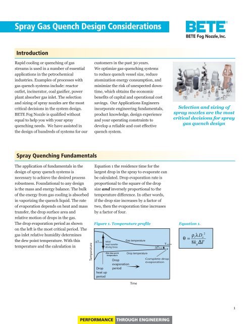
<strong>Spray</strong> <strong>Gas</strong> <strong>Quench</strong> <strong>Design</strong> <strong>Considerations</strong><strong>BETE</strong> <strong>Fog</strong> <strong>Nozzle</strong>,<strong>Inc</strong>.IntroductionRapid cooling or quenching of gasstreams is used in a number of essentialapplications in the petrochemicalindustries. Examples of processes withgas quench systems include: reactoroutlet, incinerator, coal gasifier, powerplant absorber gas inlet. The selectionand sizing of spray nozzles are the mostcritical decisions in the system design.<strong>BETE</strong> <strong>Fog</strong> <strong>Nozzle</strong> is qualified withoutequal to help you with your sprayquenching needs. We have assisted inthe design of hundreds of systems for ourcustomers in the past 30 years.We optimize gas-quenching systemsto reduce quench vessel size, reduceatomization energy consumption, andminimize the risk of unexpected downtime,which obtains the economicbenefits of capital and operational costsavings. Our Applications Engineersincorporate engineering fundamentals,product knowledge, design experienceand your operating constraints todevelop a reliable and cost effectivequench system.Selection and sizing ofspray nozzles are the mostcritical decisions for spraygas quench design<strong>Spray</strong> <strong>Quench</strong>ing FundamentalsThe application of fundamentals in thedesign of spray quench systems isnecessary to achieve the desired processrobustness. Foundational to any designis the mass and energy balance. The bulkof the energy from gas cooling is absorbedin vaporizing the quench liquid. The rateof evaporation depends on heat and masstransfer, the drop surface area andrelative motion of drops in the gas.The drop evaporation period as shownon the left is the most critical period. Thegas inlet relative humidity determinesthe dew point temperature. With thistemperature and the calculation inTemperatureEquation 1 the residence time for thelargest drop in the spray to evaporate canbe calculated. Drop evaporation rate isproportional to the square of the dropsize and inversely proportional to thetemperature difference. In other words,if the drop size increases by a factor oftwo, then the evaporation time increasesby a factor of four.Figure 1. Temperature profile Equation 1.∆TinletDropheat upperiodInitialheat transferdriving force-<strong>Gas</strong> dew pointtemperatureDropevaporationperiod<strong>Gas</strong> temperatureDrop temperature∆TfinalToutletComplete dropevaporationTime1PERFORMANCE THROUGH ENGINEERING
Symbol Variable Unitsθ Evaporation time Sρl Density of drop (liquid) Kg/m3λ Heat of vaporization of liquid J/kgD0 Drop diameter, initial, t = 0 Mkg Thermal conductivity J/m s KT Log mean temperature difference Kbetween drop and gasPenetration and dispersion of the liquiddrops into the gas stream is essential tomaximize the evaporation rate and theuniformity of the cooling. The spraypattern in process applications narrowsas the gas velocity increases. Figure 2shows the effect of gas velocity on thespray width of various drop sizes. Highgas density (elevated pressure and gascomposition) and high gas velocitydramatically reduce the spray angle.Under extreme conditions a spray cancollapse, resulting in limited dispersion ofthe drops into the gas stream. Therefore,drop trajectory calculations are essentialto assure the design will provide sufficientdrop penetration into the gas steam.Figure 2A. 2.5 m/s gas velocity.<strong>Gas</strong> velocity impact on drop trajectory with 45 psi nozzle pressure dropand 90 degree cone angle spray for 300 (red), 100 (blue) and 30 (black)micron drop diameters.2PERFORMANCE THROUGH ENGINEERING
<strong>Spray</strong> <strong>Nozzle</strong>sBecause of the wide variety ofquench system sizes, configurations,and process requirements,there is no one best nozzle for allapplications. Our design andapplication experience results inthe optimal spray nozzle choicefor your system. We assess yourneeds by determining the categoryof nozzle (single-fluid ortwo-fluid), the specific nozzle model,nozzle size, and material of construction.The range of operation from minimumcapacity to design rate to amaximum rate is also consideredin the nozzle selection. The sprayangle and the arrangement ofmultiple nozzles are also designfactors. Drop size, a critical designfactor; is affected by pressuredrop, spray angle, and nozzleorifice size as indicated inFigure 6. <strong>Inc</strong>reasing the orificesize to accommodate additional flowcan be offset with a higher-pressuredrop or a larger spray angle.Figure 6. Factors affectingdrop size.Table 1 shows specific nozzle modelsand types used in gas quench systems.Wet-wall quench designs often use singlefluidnozzles because of their simplicityand low cost. Wall washing flat fannozzles are used to control the wet-drywall interface to assure solids do notaccumulate on the wall. Dry wall systemsrequire a nozzle selection that provides amore finely atomized spray. Two-fluidnozzles are used in applications requiringa wide range of operation or when a shortevaporation time is required.<strong>Nozzle</strong> Type<strong>BETE</strong><strong>Nozzle</strong>s<strong>Quench</strong><strong>Design</strong>Table 1. <strong>Nozzle</strong> types used for quenching.<strong>Nozzle</strong> BenefitsSingle-fluid flat fan FF, SPN Wet-wall Fan pattern conformswell to wall wetting, highvelocity assures solids do notaccumulate on the wallSingle-fluid Single-fluid Wet-wall or Fine atomization, simplifiedcontrol dry-wallTwo-fluid XA, SpiralAir Dry-wall Wide operating range, finestatomization for short residencetimes, variety of spray angles.The <strong>BETE</strong> SpiralAir nozzle provideshighly efficient use of the atomizing airwith a multistage atomization process andcontrol of the spray pattern by the outletpassages design. Figure 7 shows examplesof different spray patterns that can beused to optimize the spray dependent ongas velocity, residence time, and quenchchamber dimensions.Figure 7. Spiral Air TM spray patternsgenerated by various nozzles caps.<strong>BETE</strong> offers spray nozzle lance assembliesfor single-fluid or two-fluid nozzles tomeet process and materials requirements.Many of applications have specializedmaterials of construction needs to avoidcorrosion and erosion caused by thequench liquid or the process gas. Ourdesign and fabrication capabilitiesprovide the broadest range of alloysfor the nozzle and lance to meet yourspecific needs. We have fabricatedquench nozzle lances from manydifferent materials, such as stainlesssteel alloys, chrome alloys, nickel alloys,cobalt alloys, titanium, and duplexstainless steel alloys.Figure 8. Lateral header withtwo-fluid nozzles.5PERFORMANCE THROUGH ENGINEERING
Reliability <strong>Considerations</strong>System reliability is influenced by manyfactors. Solids in the quench liquid areoften the root cause of the two mainfactors that cause system downtime,plugging, and erosion of nozzles.Solids in the quenching media maycause nozzle clogging. Plugging internalpassages of the spray nozzle leads tonon-uniform and inadequate gas cooling.It is important to select the correct nozzledesign and material of construction tomaximize free-passage, reduce cloggingand extend operating life. A strainersystem in the upstream piping can alsoprotect nozzles and maintain the nozzleperformance by preventing repair workand unnecessary equipment shut downs.the drop size. Wear and erosion of nozzlesdepends on process specific conditionssuch as; the velocity of the liquid, thehardness of the particles in the liquid andthe corrosive nature of the environment.Operational experience is frequently thebest guide to assessing if erosion is areasonable concern. Material selection isalso an important design factor tominimize nozzle wear and extend thesystem operating life. <strong>BETE</strong> has themanufacturing capability and engineeringexperience to assist you in selecting themost appropriate nozzle constructionmaterial to withstand the operatingenvironment.The second factor is the erosion ofinternal passages and nozzle outlet thatdistorts the spray pattern and increasesProcess controlThe process control of quench systemsmust be considered in the design phaseto achieve the optimal result. The quenchliquid flow is often controlled to achievea desired quench zone exit temperature.Instrumentation to monitor single-fluidnozzle pressure drop is frequently used.Two-fluid nozzles require a morethoughtful and deliberate approach tocontrol the atomizing gas and the liquidflow. One objective of nozzle control isto minimize the amount of atomizinggas (compressed air) and therefore,reduce the energy input to supply theatomizing media. Improved controlreduces operational cost and stabilizesthe system response to extremeconditions.Wet-wall conceptThe design of many wet wall quenchesinvolves little process control becausea constant liquid pressure is used tocontinually maintain the maximumrequired flow. This assures thequench spray system is always atpeak performance. Highly variable inletgas flows are robustly quenched with thissimple control approach. The measuredpressure drop is crosschecked with theexpected spray nozzle pressure dropbased on the measured flow. Thismeasurement is valuable to identifyany gross issues with the nozzles orflow measuring device. Control systemshave many conditions that need to beevaluated. The spray design must beable to manage the possible situationsgiven the combinations of flow pathsand range of flows.6PERFORMANCE THROUGH ENGINEERING
Dry-wall conceptSingle fluid nozzles are often used witha narrow range of gas throughput, andwhere multiple lances are used to managegreater turndown requirements. Thequench temperature control systemdetermines the flow rate of quenchliquid. Pressure drop control is used withmultiple lances to maintain a minimumpressure drop to assure the drop size issmaller than a predetermined value.Turndown to less than 75% of designis managed by controlling the flow tothe groups of nozzles to maintain therequired drop size, as described in thefirst example.Conventional flow control for two-fluidnozzles, shown in Figure 9, often usedin dry-wall quench systems providesexcellent and robust control. Numerouscontrol strategies can be implementedbased on overall system and processrequirements. The design of large-scalesystems with several second residencetime, should consider the gas transit timefrom the spray to sensor as lag-time ordead time between controller action andthe sensor response. This dead time variesdepending on throughput and inputtemperature. Numerous potential controlstrategies can be implemented based onoverall system requirements. One is afeed forward set point based on inlettemperature and mass flow. Multimodecontrollers using the combination of feedforwardand feedback provide additionalrobustness, but add complexity.Control of two-fluid nozzles is morecomplex than single-fluid nozzles;however, the range of operation is muchbroader. The myth is evaporation timeis controlled by constant drop size. Thereality is that under turndown conditionsthe gas residence time is longer andconsequently the drop size requiredcan be larger than in the maximum rateconditions. The flow control systemdescribed in Figure 10 can be used forinternal-mix or external-mix nozzle types.Internal-mix two-fluid nozzles needspecial attention on controller tuningbecause of the interaction between thegas and liquid control loops. For example,a slight increase in the liquid flow in asystem with two independent mass flowcontrollers causes an increase in nozzleFT<strong>Quench</strong> Liquid<strong>Quench</strong> LiquidFTFTAtomizing <strong>Gas</strong>FCFCFCStrainerPTStrainerSingle Fluid <strong>Quench</strong> <strong>Nozzle</strong> System ConfigurationFigure 9.PTCheck ValvePTTwo Fluid <strong>Quench</strong> <strong>Nozzle</strong> System ConfigurationFigure 10.pressure drop which in turn causes thegas control valve to open. These actionsresult in feedback to the liquid controlloop and ultimately overshoot of theliquid flow. The non-linear feedback cancause oscillatory behavior if the controllertuning parameters of the gas and liquidflows are not coordinated.Back flow prevention is critical ininternal-mix two-fluid nozzle piping toassure quench liquid does enter thecompressed air header. Several featureshave been incorporated into the systemas shown in Figure 13, recommendedmeasurements of the flow and nozzlepressure drop for both the gas andliquid streams.<strong>BETE</strong> Applications Engineering expertisecan reduce the initial and long term costof the quenching operation system.Process gasflowProcess gasflowFCFTPTControl ValveStrainerCheck ValveFlow Rate ControllerFlow Rate TransmitterPressure TransmitterSignal7PERFORMANCE THROUGH ENGINEERING
Maintenance <strong>Considerations</strong>Maximum reliability can often beenhanced with simple system configurationsuch as strainers to prevent smallamounts of solids from plugging nozzles,as mentioned above. If nozzles are subjectto high temperature environments anddo not continually have a flow of liquidor atomizing gas, the nozzle will overheatand material failure can result. The risk ofan unplanned shutdown is reduced withscheduled maintenance to manage wearor erosion of nozzles and to inspect forpartial clogging and overheating nozzles.We recommend visual inspection and thedevelopment of a routine replacementplan. Some systems require nozzlechange-out every 1 to 2 years to fullymaintain the process performance. Forclean liquid service an annual inspectionis a starting point for a PM (PreventativeMaintenance) program.Examples of <strong>Spray</strong> <strong>Quench</strong> ApplicationsThe examples below provide aperspective on the range of designsand considerations involved insystem design.Pressurized <strong>Gas</strong> <strong>Quench</strong>A large-scale reactor gas dry wall quenchsystem was used by a customer to cool apressurized gas stream (~100 psi) from1000° C to 250°C to protect downstreamequipment. Because this system wasrefractory lined, a dry-wall design wasessential to prevent excessive thermalstresses on the refractory. A high degreeof turndown (8:1) was necessary tomanage conditions from startup to fullrate operation. The system geometry,shown in Figure 11, had a short distancebetween the liquid injection point and theend of the refractory lining. The customerinitially used a nozzle (not from <strong>BETE</strong>)that cooled only to 500° C. The nozzleused was a spring-loaded pintle typedesigned as a steam-desuperheatingnozzle, which resulted in a large dropsize at a higher flow. <strong>BETE</strong> ApplicationsEngineering analysis showed theexcessive drop size produced by thisnozzle and the system configuration werethe root causes of inadequate cooling.The spray impinged on the refractory walland liquid flowed at the bottom of thepiping. The surface area of the liquidstream flowing co-currently with the gaslimited the ineffective heat transfer.The system designed in collaboration<strong>BETE</strong> Applications Engineering was agroup of 19 <strong>BETE</strong> TF 8 FC nozzlesarranged as shown Figure 11B. Thesewere sized to operate at a pressure dropof 200 psi to achieve the desired dropsize and spray penetration into the highvelocity gas steam. The system requiredthe addition of a high-pressure centrifugalpump to deliver quench water to the spraynozzles. Three lateral headers were usedto manage the turndown. At low rate onlyone header would be in operation and agas purge would cool the other headers.Full rate operation would have all threeheaders in operation.The resulting quench system design onlyrequired fine-tuning of the transitionpoints between the operation of one, two,and three headers. High reliability wasachieved with careful consideration of allthe operating modes and proper materialselection even though the spray lanceswere in a harsh high temperatureenvironment.<strong>Quench</strong>LiquidCooled gasoutletHot gas inletFigure 11A. Cross section oforiginal system showing nozzlecentrally mounted in the 1 meterID system.Header 1Header 2Header 3Figure 11B. End view of headersystem and nozzles.8PERFORMANCE THROUGH ENGINEERING
Acid <strong>Gas</strong> <strong>Quench</strong>A customer’s acid gas recovery fromenergy efficient thermal treatmentsystems required the cooling ofHydrogen Chloride acid gas betweena heat recovery boiler exit from 250° Cto 50° C at the entrance of an absorptiontower. The quench liquid for this wet-walldesign was the strong acid from theabsorber tower. As with many wet-walldesigns, the amount of evaporation of thequench liquid is approximately 10%.Entrainment of small droplets into thepacked tower reduces the countercurrentabsorption efficiency. Therefore, a largerdrop size with sufficient surface area forheat transfer was needed. A cost effectivesolution was required that was compatiblewith the corrosive hot aqueous HCl.The nozzle selected by <strong>BETE</strong> ApplicationsEngineering <strong>BETE</strong> TF 16 FC made fromglass filled PTFE. This material choiceallows operations with HCl at approximately30 psi to achieve the drop size of350 micron required for the heat transfer.These nozzles were mounted in anejector venturi inducing gas flowthrough the system.<strong>Gas</strong> Cooling ExampleA confidential process being developedby a customer required the cooling gasstream to be instantaneous and uniform.The drop size needed to achieve the50-millisecond evaporation time andquench liquid flow rate restricted thenozzle type to the two-fluid nozzle. Steamwas chosen as the atomizing gas mediumbecause any non-condensable gas wouldadd to the overall process complexity.The <strong>BETE</strong> XASR external-mix nozzlewas selected to allow the most efficientuse of steam. An internal mix nozzlewould have required additional steamto preheat the liquid to saturation.The process performance met allexpectations for the entire range ofoperating conditions and rates.SummaryAn optimized spray quench designrequires engineering analysis of theoperating environment, spray nozzleperformance and process reliability.<strong>BETE</strong> Applications Engineers willpartner with you to develop andoptimize the quench system for yourapplication. Our analysis tools andexperience with hundreds of applicationsprovide a rapid and robust engineeringdesign of your spray quench system.The result is a quench system thatoperates efficiently and reliably foryour process.<strong>BETE</strong> <strong>Fog</strong> <strong>Nozzle</strong>,<strong>Inc</strong>.50 Greenfield St.Greenfield, MA 01301 USAT (413) 772-0846F (413) 772-6729www.bete.com9PERFORMANCE THROUGH ENGINEERING