GWC005DC1- GWC024DC1 - GEA Happel Belgium
GWC005DC1- GWC024DC1 - GEA Happel Belgium
GWC005DC1- GWC024DC1 - GEA Happel Belgium
- No tags were found...

You also want an ePaper? Increase the reach of your titles
YUMPU automatically turns print PDFs into web optimized ePapers that Google loves.
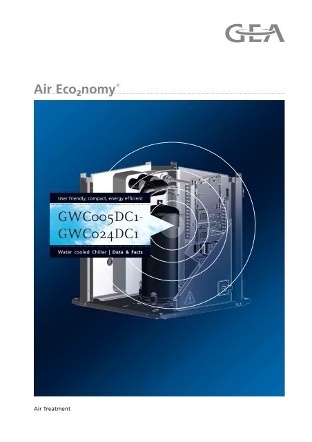
User friendly, compact, energy efficient<strong>GWC005DC1</strong>-<strong>GWC024DC1</strong>Water cooled Chiller | Data & FactsAir Treatment
Table of ContentsGWC 005-024 DC1Overview ............................................................................................ 3Unit Description ................................................................................ 4<strong>GEA</strong> GWC Series ...................................................................................................... 4Components .............................................................................................................. 5Options ...................................................................................................................... 6Unit size GWC 005-024 DC1 ............................................................. 7General technical data .............................................................................................. 7Electrical data ........................................................................................................... 8Performance data ............................................................................ 10Cooling/Heating capacity tables GWC 005-012 DC1 .............................................. 10Cooling/Heating capacity tables GWC 016-024 DC1 .............................................. 11Capacity tables ................................................................................ 12Capacity correction factor ........................................................................................ 12Dimensional drawing & centre of gravity ..................................... 13Dimensional drawing GWC 005-012 DC1 ............................................................... 13Dimensional drawing GWC 016-024 DC1 ............................................................... 14Centre of gravity ...................................................................................................... 15Piping diagram ................................................................................ 16GWC 005-012 DC1 ................................................................................................. 16GWC 016-024 DC1 ................................................................................................. 17Wiring diagram ................................................................................ 18Sound data ...................................................................................... 20Sound power spectrum ........................................................................................... 20Operation range .............................................................................. 21Hydraulic performance ................................................................... 22Water pressure drop curve evaporator/condenser .................................................. 22Protection NoticesThe reproduction, distribution and utilization of this document as well as the communication of its contentsto others without express authorization is prohibited. Offenders will be held liable for the payment of damages.All rights reserved in the event of the grant of a patent, utility model od design.2 PR-2008-0323-GB • Subject to modifications • Status 09/2008
GWC 005-024 DC1Overview– Scroll compressor– Optimised for use with R-407C– Electronic DDC controller– Low operating sound level– Low energy consumption– Compact dimensions and low refrigerant volume– Easy installation and maintenance– Stainless steel plate heat exchanger– Remote cooling or heating selection– Water/water heat pump, with water reversibility– Compatible with hydraulic module– For GWC 005-024 DC1 following components are standard– included: main switch, pressure ports, flow switch, filter, shut-off valves– and air purge.Pic. 1:GWClow noiseoperationScrollcompressorPR-2008-0323-GB • Subject to modifications • Status 09/2008 3
Unit Description<strong>GEA</strong> GWC SeriesGWC 005-024 DC1Compact, modular design water-cooled chiller for indoor installation IP20 - manufacturedaccording to the lSO 9001 quality standard. The GWC-DC1 range has been designedfor both air conditioning and process cooling applications. The use of state-ofthe-arttechnologies and high quality materials ensures efficiency, reliability and anextended service life.ComponentsEach <strong>GEA</strong> chiller is subjected to many hours of test runs in the factory allowing for standardrequirements.Casing / ColourPowder coated, galvanised steel plate. Fully factory assembled on a base frame.Colour ivory white ( ± RAL 7044) / Munsell code 5Y7.5/1Number of cooling circuitsUnit 005-012: single circuit,Unit 016-024: double circuit.Each refrigerant circuit has its own independent design thereby guaranteeing a highlevel of system reliability. The GWC 016-024 DC1units have 2 plate heat exchangers(two refrigerant circuits / one water circuit) in order to minimise the hydraulic installationoverhead.CompressorOne R-407C optimised fully hermetically sealed scroll type compressor per refrigerantcircuit. As a design requirement, this compressor characteristically offers extremelysmooth performance, efficiency and operational reliability. Each compressor is mountedin the unit with vibration isolation and fitted with a compressor motor overcurrent(Klixon).CondenserR-407C optimised counter flow plate heat exchanger made of stainless steel, platesbrazed gastight with copper, for water and glycol mixtures. The water pressure may notexceed the maximum permissible operating pressure of 10 bar!Evaporatorspecial refrigerant distribution system has been incorporated into the plate duct foroptimal capacity of the complete heat transmission surface.As well as an additional increase in efficiency, this is also responsible for stable controlbehaviour in the heat exchanger. The plate heat exchanger is heatinsulated to ensureit is diffusion-proof to prevent any heat loss.Electronic contactor and water filter as standard. The water pressure may not exceedthe maximum permissible operating pressure of 10 bar!4 PR-2008-0323-GB • Subject to modifications • Status 09/2008
GWC 005-024 DC1Unit DescriptionComponentsPipingConsisting of Cu pipe with all the necessary cooling fittings such as:– Service valves,– Filter dryer,– thermostatic expansion valve with external pressure equalisation.The plate heat exchanger is cased with galvanised steel.Safety and control devicesEach refrigerant circuit is fitted with the following safety devices:– High- and low-pressure switch,– hot gas temperature monitoring,– compressor thermal cut-out,– overload relay,– frost protection.Each refrigerant circuit is fitted with the following control devices:– Electronic temperature monitoring,– phase-sequence relay,– timing safety device and– switch frequency limiter.Switching and control deviceIn addition to the fully automated -Chiller digital controller (manufactured by CARREL),the control cabinet manufactured in accordance with the valid EN directives (CE) containsall the required switching and control components such as:– Main switch,– load,– auxiliary and control cut-outs,– transformers,– control fuses,– relay and auxiliary relay,– sensors,– -Chiller digital controller.The electronics have an automatic restart after power failure and provide the followingdigital inputs and outputs hard-wired to terminals for incorporating the GLT:Tab. 1Digital inputsContactorPump contactRemote On/OffCooling/heatingDigital outputsCollection fault messageGeneral operating messageOperating message per compressorCold water pump driveReversing valvePR-2008-0323-GB • Subject to modifications • Status 09/2008 5
Unit DescriptionOptionsGWC 005-024 DC1Chiller digital controllerThe GWC-DC1 units are fitted with a digital controller, which allows the user to configure,operate and service the unit in a user-friendly manner. The -Chiller digital controllerconsists of a numerical display, 4 control keys and 4 LEDs.The following functions are supported by the electronics, amongst other things:– Allocation of the set point and the desired switching hysteresis– Cold water return controller (cooling mode)– Chilled water return controller (heating mode)– Allocation of pump lead times/overrun times– Allocation of service intervals– Displaying the current operating parameter such as flow and return temperatures– Recording operating hours (compressor/pump)– Fault code query– Password protectionAs an option this chiller can be fitted with an interface for integrating it into a BuildingManagement System (BMS), which either supports the MODbus/J-bus or BACnet protocol.OptionsDescription Option description Unit size Availability005 008 010 012 016 020 024Standard unit ✓ ✓ ✓ ✓ ✓ ✓ ✓Not completely combinable optionsGZWCGLYCC.O04 Glycol application chilled water temperature down to -5 °C ✓ ✓ ✓ ✓ ✓ ✓ ✓GZWCGLYCC.O05 Glycol application chilled water temperature down to -10 °C ✓ ✓ ✓ ✓ ✓ ✓ ✓FactorymountedFactorymountedAvailable kitGZWCSMBCC.E09 BMS gateway modbus / j-bus protocol ✓ ✓ ✓ ✓ ✓ ✓ ✓ KitGZWCSBNCC.E10 BMS gateway bacnet protocol ✓ ✓ ✓ ✓ ✓ ✓ ✓ KitGZWCAC1CC.E08 BMS card ✓ ✓ ✓ ✓ ✓ ✓ ✓ KitGZWCRUMCC.E01 Remote controller ✓ ✓ ✓ ✓ ✓ ✓ ✓ KitGZWC005CC.I17 Low noise operation GWC 005 DC1 ✓ 1 – – – – – – KitGZWC008..012CC.I17 Low noise operation GWC 008-012 DC1 – ✓ 1 ✓ 1 ✓ 1 – – – KitGZWC016..024CC.I17 Low noise operation GWC 016-024 DC1 – – – – ✓ 2 ✓ 2 ✓ 2 KitGHM10A41/48 Hydraulic module, Buffer tank with pump ✓ ✓ – – – – – KitGHM15A41/48 Hydraulic module, Buffer tank with pump – – ✓ ✓ – – – KitGHM30A41/48 Hydraulic module, Buffer tank with pump – – – – ✓ ✓ ✓ KitTab. 2NotesSymbols* = Option number std = standard on unit- To install GZWCSMBCC.E09, GZWCSBNCC.E10 and GZWCRUMCC.E01=> GZWCAC1CC.E08 needs to be installed on the unit..✓✓x-AvailableAvailable and a quantity of x is needed for this unit size.Not availableHatched area = preliminary data6 PR-2008-0323-GB • Subject to modifications • Status 09/2008
GWC 005-024 DC1Unit size GWC 005-024 DC1General technical dataUnit size 005 008 010 012 016 020 024Capacity* Cooling Nominal [kW] 13.0 21.5 28.0 32.5 43.0 56.0 65.0Capacity Steps [%] 1 1 1 1 2 2 2Nominal input* Cooling [kW] 3.61 5.79 7.48 8.75 11.80 15.50 17.60Casing Material Polyester painted steel plateDimensionsUnitHeight [mm] 600 600 600 600 600 600 600Width [mm] 600 600 600 600 600 600 600Depth [mm] 600 600 600 600 1200 1200 1200Weight Unit [kg] 118 155 165 172 300 320 334Water HeatExchangerCompressorTypeMinimum water volumein the systemWater flowrateGelötete Edelstahl-Plattenwärmetauscher[l] 62 103 134 155 205 268 311Min. [l/min] 19 31 40 47 62 80 93Nominal [l/min] 37 62 80 93 123 161 186Max. [l/min] 75 123 161 186 247 321 373Insulation materialPolyethylene foamModel Quantity n 1 1 1 1 1 1 1TypeBrased plateWater flowrateMin [l/min] 24 39 51 59 79 102 118Nominal [l/min] 48 78 102 118 157 205 237Max [l/min] 95 157 203 237 314 410 474Modell Quantity 1 1 1 1 1 1 1TypeVollhermetischer ScrollverdichterRefrigerant oil typeDaphne FVC68DRefrigerant oil charge[l] 1.5 2.7 2.7 2.7 2.7 2.7 2.7[l] – – – – 2.7 2.7 2.7Quantity n 1 1 1 1 2 2 2TypeModelJT140BF-YEJT212DA-YEJT300DA-YEJT335DA-YEJT212DA-YEJT300DA-YEJT335DA-YESpeed [U/min] 2900 2900 2900 2900 2900 2900 2900Sound Level Sound Power Cooling [dBA] 64 64 64 71 67 67 74Refrigerant typeR-407CRefrigerant circuitRefrigerant charge [kg] 1.2 2.0 2.5 3.1 4.6 4.6 5.6No of circuits n 1 1 1 1 2 2 2Refrigerant controlThermostatic expansion valvePipingconnectionsEvaporator water inlet/outletCondensor water inlet/outletFBSP 25 FBSP 25 FBSP 25 FBSP 25 FBSP 40 FBSP 40 FBSP 40field installationFBSP 25 FBSP 25 FBSP 25 FBSP 25 FBSP 40 FBSP 40 FBSP 40field installationNotes Capacity is for chilled water range Δt = 2˜5 °CPower input is total input (kW) : compressor + control circuit + pumpsWater flow rate (WFR) = (860 x CC)/(60 x Δt) in (l/min) = ((860 x CC)/(60 x Δt)) x (1/60000) in m³/s (CC = coolingcapacity from table (kW)/ Δt = chilled water temperature rise within 2˜5 °C / WFR should always be within the limits).No pumps are supplied with the unit, so the added power input for the pumps is calculated as (WFR (m³/s) x Δp (Pa))/0.3 (as fixed by 6/C/003). This is for the cooled and cooling water (DP = pressure drop from pressure drop curves).A filter strainer must be added in the water circuit of the evaporator and the condensor. A flow switch must be providedat the evaporator side. Min. water volume system applicable at nominal conditions.Nominal cooling capacities are based on the following conditions: Evaporator: 12 °C/7 °C, condenser 30 °C/35 °CThe sound power level is an absolute value indicating the ’’power’’ which a sound source generates.The sound data is valid at nominal operation condition dB(A) = A-weighted sound power level (A-scale according to IEC)Reference acoustic pressure 0 dB = 1 pW. Measured according to ISO9614* Eurovent conditions specified in notesPR-2008-0323-GB • Subject to modifications • Status 09/2008 7
Unit size GWC 005-024 DC1Electrical dataGWC 005-024 DC1Unit size 005 008 010 012 016 020 024SupplyUnitCompressorNamePhaseFrequency [Hz] 50 50 50 50 50 50 50Voltage [V] 400 400 400 400 400 400 400VoltageToleranceW1Min. [%] -10 %Max. [%] +10 %Starting Current [A] 49 79 109 129 93 127 149Nominal RunningCurrentCooling[A] 6.6 10.4 13.1 15.0 20.8 26.2 30.0Max. Running Current [A] 9 14.5 18.5 22 28 36 40Recommended fuses accordingto IEC standard269-23N3x16aM 3x20aM 3x25aM 3x25aM 3x35aM 3x40aM 3x50aMPhase 3 3 3 3 3 3 3Voltage [V] 400 400 400 400 400 400 400Starting current (soft start) [A] 49 79 109 129 79 109 129Nominal running current(RLA)[A] 6.6 10.4 13.1 15.0 10.4 13.1 15.0Max. Running Current [A] 9.0 14.5 18.5 22.0 14.0 18.0 20.0Starting MethodDirect on line8 PR-2008-0323-GB • Subject to modifications • Status 09/2008
GWC 005-024 DC1The digital controller consists of a numeric display, four labelledkeys which you can press an four LEDs providing extra user information.Pic. 2:Digital controllerKeys provided on the controller:Each key, except for , combines two functions: /, / and / . The function carried out whenthe user presses one of these keys depends on the statusof the controller and the unit at that specificmoment.Key, to enter the scroll list of user parameters, toconfirm a parameter modification and to return tonormal operation.Key, to de-activate the buzzer in the case of analarm.LEDs provided on the controller:LED, indicates the status of the compressor.The LED does not light up when the compressor isnot active, blinks when the compressor cannotstart up although extra load is requested (e.g.timer active) and lights up permanently when thecompressor is active.LED, indicates that heating mode is active.Key, to scroll through the list of direct or user parametersor to raise a setting.LED, indicates that cooling mode is active.Key, to start the unit in heating mode or to switchthe unit off when heating mode is active.LED, indicates that the value on the numeric displayshould be multiplied by 100.Key, to enter the scroll list of direct parameters orto switch between a parameter’s code and itsvalue.Key, to start the unit in cooling mode or to switchthe unit off when cooling mode is active.Key, to scroll through the list of direct or user parametersor to lower a setting.PR-2008-0323-GB • Subject to modifications • Status 09/2008 9
Performance dataCooling/Heating capacity tables GWC 005-012 DC1GWC 005-024 DC1LWC 20 25 30 35 40 45 50 55LWE-10-504710141620TypTab. 3CC HC PI CC HC PI CC HC PI CC HC PI CC HC PI CC HC PI CC HC PI CC HC PI005 8,0 10,8 2,75 7,5 10,5 2,95 7,0 10,2 3,20 6,4 9,9 3,49 5,7 9,6 3,82 5,0 9,2 4,19 – – – – – –008 12,4 16,0 3,55 12,2 16,2 4,02 11,5 16,1 4,53 10,7 15,8 5,08 9,8 15,4 5,66 8,7 15,0 6,29 – – – – – –010 16,4 21,6 5,18 16,4 22,2 5,80 16,1 22,6 6,50 15,3 22,6 7,29 14,3 22,4 8,17 12,9 22,1 9,14 – – – – – –012 20,9 27,0 6,12 20,8 27,4 6,69 20,6 28,0 7,41 19,7 28,0 8,27 18,2 27,5 9,29 16,3 26,7 10,47 – – – – – –005 9,9 12,7 2,75 9,4 12,4 2,97 8,9 12,1 3,23 8,3 11,8 3,56 7,6 11,5 3,87 6,9 11,2 4,25 6,2 10,9 4,63 – – –008 15,9 19,7 3,77 15,4 19,6 4,25 14,7 19,5 4,77 13,9 19,2 5,34 12,9 18,9 5,95 11,8 18,4 6,61 10,5 17,8 7,31 – – –010 20,1 25,4 5,35 20,1 26,0 5,94 19,8 26,4 6,62 18,9 26,3 7,40 18,1 26,4 8,26 16,8 26,0 9,22 154 25,6 10,28 – – –012 24,4 30,6 6,25 24,3 31,1 6,84 24,1 31,7 7,56 23,3 31,8 8,42 22,0 31,5 9,42 20,2 30,9 10,61 18,0 29,8 11,81 – – –005 11,9 14,7 2,77 11,4 14,4 3,00 10,9 14,2 3,27 10,3 13,9 3,60 9,7 13,6 3,94 8,9 13,3 4,33 8,1 12,9 4,73 7,3 12,5 5,23008 18,8 22,8 4,01 18,3 22,8 4,46 17,6 22,5 4,97 16,8 22,4 5,55 15,8 22,0 6,18 14,7 21,5 6,88 13,4 21,0 7,64 12,1 20,5 8,45010 23,7 29,2 5,46 23,7 29,7 5,99 23,4 30,1 6,63 22,6 30,0 7,37 21,9 30,1 8,21 20,6 29,8 9,14 19,2 29,4 10,18 17,2 28,5 11,31012 27,9 34,2 6,22 27,8 34,7 6,87 27,7 35,3 7,62 26,9 35,4 8,49 25,7 35,2 9,47 24,1 34,9 10,74 22,0 33,8 11,75 19,5 32,7 13,17005 13,1 15,8 2,73 12,9 15,9 2,99 12,5 15,8 3,28 12,0 15,7 3,63 11,4 15,4 3,97 10,7 15,1 4,37 10,0 14,8 4,79 9,1 14,4 529008 20,8 24,9 4,07 20,6 25,1 4,55 20,2 25,3 5,08 19,8 25,5 5,67 18,8 25,1 6,31 17,7 24,7 7,01 16,4 24,1 7,76 14,6 23,2 8,56010 26,7 32,2 5,51 26,7 32,7 6,05 26,4 33,1 6,70 25,7 33,2 7,49 24,9 33,2 8,29 23,7 32,9 9,22 22,2 32,5 10,24 20,3 31,8 11,47012 30,8 37,2 6,44 30,7 37,8 7,09 30,6 38,4 7,85 30,0 38,7 8,71 28,9 38,6 9,71 27,5 38,3 10,80 25,6 37,6 12,00 23,4 36,7 13,27005 14,3 17,1 2,76 14,0 17,0 3,00 13,5 16,8 3,29 13,0 16,6 3,61 12,3 16,3 3,98 11,6 16,0 4,37 10,9 15,7 4,84 10,1 15,4 5,33008 22,7 26,9 4,24 22,5 27,2 4,66 22,2 27,4 6,17 21,5 27,3 5,79 20,5 26,9 6,35 19,2 26,2 7,00 17,6 25,4 7,75 15,6 24,3 8,69010 28,9 34,5 5,66 28,9 35,0 6,11 28,6 35,4 6,76 28,0 35,4 7,48 27,1 35,5 8,35 26,0 35,2 9,25 24,5 34,8 10,32 22,6 34,1 11,45012 33,1 39,6 6,52 33,01 40,2 7,19 33,0 40,9 7,95 32,5 41,2 8,75 31,5 41,3 9,81 30,1 41,0 10,90 28,1 40,2 12,12 25,7 39,0 13,33005 15,5 18,2 2,76 15,1 18,1 3,03 14,8 18,1 3,33 14,3 17,9 3,64 13,7 17,8 4,05 13,0 17,5 4,46 12,2 17,2 4,92 11,2 16,6 5,35008 24,6 28,8 4,22 24,4 29,1 4,67 24,0 29,2 5,19 23,3 29,1 5,78 22,3 28,8 6,40 21,1 28,2 7,10 19,5 27,3 7,85 17,6 26,3 8,69010 30,4 35,9 5,56 30,3 36,4 6,12 30,1 36,9 6,78 29,6 37,2 7,53 29,0 37,3 8,36 27,9 37,2 9,30 26,6 36,9 10,32 24,9 36,3 11,47012 34,5 41,1 6,61 34,4 41,7 7,29 34,3 42,3 8,05 33,7 42,6 8,90 32,8 42,7 9,89 31,4 42,4 10,97 29,6 41,8 12,14 27,5 40,9 13,37005 16,2 19,0 2,75 16,2 19,2 3,06 16,2 19,6 3,38 16,0 19,7 3,67 15,6 19,7 4,12 14,9 19,5 4,55 14,0 19,0 5,02 12,6 18,2 5,37008 26,4 30,6 4,20 26,3 31,0 4,68 26,2 31,4 5,21 25,7 31,5 5,75 24,8 31,3 6,46 23,6 30,8 7,19 22,0 30,0 7,98 20,2 28,9 8,68010 32,3 37,8 5,56 32,2 38,3 6,13 32,2 38,9 6,76 31,9 39,5 7,55 31,4 39,8 8,37 30,6 39,9 9,29 29,4 39,8 10,31 27,9 39,4 11,49012 38,4 45,0 6,67 38,3 45,7 7,35 38,0 46,1 8,12 37,4 46,4 9,00 36,5 46,4 9,94 35,2 46,2 10,98 33,7 45,6 12,11 31,0 44,4 13,36005 16,7 19,5 2,74 16,7 19,8 3,06 16,7 20,0 3,38 16,5 20,2 3,68 16,2 20,3 4,13 15,6 20,2 4,55 14,8 19,8 5,01 13,7 19,0 5,37008 27,2 31,4 4,19 27,1 31,8 4,67 27,0 32,2 5,20 26,6 32,4 5,74 25,8 32,3 6,45 24,7 31,9 7,17 23,2 31,2 7,96 21,5 30,1 8,68010 32,6 38,2 5,57 32,6 38,7 6,15 32,5 39,3 6,82 32,3 39,9 7,58 31,9 40,3 8,41 31,2 40,5 9,34 30,2 40,6 10,36 28,9 40,4 11,49012 38,8 45,5 6,70 38,7 46,1 7,39 38,5 46,7 8,17 38,1 47,1 9,06 37,3 47,3 9,99 36,1: 47,2 11,03 34,7 46,8 12,16 32,9 46,4 13,43005 17,6 20,3 2,73 17,6 20,6 3,05 17,5 20,9 3,38 17,5 21,2 3,69 17,4 21,5 4,12 17,0 21,5 4,54 16,3 21,3 4,99 15,4 20,7 5,36008 28,9 33,0 4,16 28,8 33,4 4,64 28,7 33,9 5,17 28,5 34,2 5,71 28,0 34,4 6,41 27,0 34,2 7,13 25,8 33,7 7,92 24,0 32,6 8,67010 33,2 38,8 5,58 33,2 39,4 6,19 33,1 40,0 6,66 33,1 40,8 7,63 32,9 41,4 8,49 32,4 41,9 9,42 31,8 42,2 10,44 31,0 42,5 11,50012 40,9 47,6 6,67 40,8 48,2 7,38 40,8 49,0 8,17 40,7 49,8 9,09 40,7 50,7 9,98 40,6 51,6 11,02 39,2 51,3 12,14 37,4 50,9 13,49NotesSymbols1 Cooling capacity is according to Eurovent rating standard6/C/003-2003 and valid for chilled water range Δt = 3~8 °C.CC : Cooling capacity (kW)HC : Heating capacity (kW)2 Heating capacity is according to Eurovent rating standard6/C/003-2003 and valid for chilled water range Δt = 3~8 °C.PI : Power input (kW)LWE : Leaving Water Evaporator (°C)3 Power input is total input according to Eurovent rating standard. LWC : Leaving Water Condenser (°C)10 PR-2008-0323-GB • Subject to modifications • Status 09/2008
GWC 005-024 DC1Performance dataCooling/Heating capacity tables GWC 016-024 DC1LWC 20 25 30 35 40 45 50 55LWETypCC HC PI CC HC PI CC HC PI CC HC PI CC HC PI CC HC PI CC HC PI CC HC PI-10016 24,8 32,2 7,5 24,3 32,7 8,5 23,0 32,4 9,5 21,4 31,9 10,6 19,5 31,1 11,7 17,3 30,2 13,0 – – – – – –020 32,9 43,5 10,8 32,9 44,8 12,1 32,2 45,5 13,5 30,7 45,5 15,1 28,6 45,2 16,8 25,9 44,5 18,8 – – – – – –024 41,9 54,2 12,3 41,5 55,0 13,5 41,2 55,9 14,9 39,4 55,8 16,6 36,5 55,0 18,7 32,5 53,3 21,0 – – – – – –-5016 31,8 39,7 8,0 30,6 39,5 8,9 29,4 39,2 10,0 27,7 33,7 11,1 25,7 38,0 12,3 23,5 37,1 13,6 20,9 35,9 15,0 – – –020 40,2 51,2 11,2 40,2 52,4 12,4 39,7 53,2 13,7 37,8 52,9 15,3 36,3 53,2 17,0 33,7 52,5 18,9 30,8 51,7 21,0 – – –024 48,7 61,4 12,6 48,6 62,4 13,8 48,3 63,4 15,2 46,7 63,5 16,9 44,1 62,8 18,9 40,5 61,6 21,3 36,0 59,4 23,7 – – –0016 37,4 45,8 8,4 36,5 45,8 9,3 35,1 45,4 10,4 33,6 45,1 11,5 31,5 44,3 12,8 29,2 43,4 14,2 26,7 42,3 15,7 24,1 41,4 17,3020 47,5 58,7 11,4 47,5 59,8 12,5 46,9 60,5 13,7 45,3 60,4 15,2 43,8 60,6 16,9 41,3 60,0 18,8 38,5 59,2 20,8 34,4 57,4 23,1024 55,9 68,6 12,5 55,6 69,5 13,8 55,4 70,7 15,3 53,9 70,9 17,1 51,5 70,4 19,0 48,2 69,6 21,6 44,1 67,4 23,6 39,0 65,2 26,44016 43,6 51,9 8,3 42,5 51,8 9,3 41,1 51,5 10,3 39,5 51,1 11,5 37,5 50,3 12,8 35,2 49,5 14,2 32,7 48,4 15,7 30,1 47,4 17,3020 53,5 64,9 11,5 53,5 66,0 12,6 52,8 66,6 13,9 51,5 66,9 15,5 49,8 66,8 17,1 47,5 66,3 18,9 44,5 65,4 21,0 40,7 64,0 23,4024 61,6 74,9 13,0 61,5 76,0 14,3 61,1 77,0 15,8 59,9 77,5 17,5 57,9 77,4 19,5 55,0 76,6 21,7 51,3 75,2 24,1 46,9 73,3 26,67016 46,4 55,1 8,6 45,9 55,4 9,5 44,7 55,3 10,5 43,0 54,8 11,8 40,9 53,9 12,9 38,3 52,5 14,2 35,1 50,8 15,7 31,1 48,7 17,5020 57,9 69,4 11,6 57,9 70,5 12,7 57,3 71,2 14,0 56,0 71,4 15,5 54,4 71,5 17,2 52,0 71,0 18,9 49,1 70,2 21,1 45,3 68,6 23,3024 66,2 79,4 13,1 66,1 80,5 14,5 65,9 82,0 16,0 65,0 82,7 17,6 63,1 82,8 19,7 60,2 82,0 21,8 56,3 80,4 24,3 51,3 77,9 26,810016 49,1 57,8 8,6 48,7 58,3 9,5 47,9 58,5 10,6 46,6 58,3 11,7 44,6 57,6 13,0 42,0 56,5 14,4 38,9 54,8 15,9 35,1 52,7 17,6020 60,9 72,4 11,6 60,7 73,4 12,7 60,3 74,3 14,0 59,4 74,8 15,5 58,0 75,2 17,2 56,0 75,0 19,1 53,3 74,4 21,1 49,8 73,1 23,4024 69,0 84,1 13,3 68,9 85,2 14,7 68,5 86,5 16,2 67,5 87,1 17,9 65,5 87,1 19,9 62,8 86,5 22,0 59,3 85,2 24,4 55,0 83,3 26,814016 52,6 61,3 8,6 52,5 62,1 9,5 52,2 62,9 10,6 51,3 63,1 11,7 49,5 62,6 13,1 47,1 61,7 14,5 43,9 60,1 16,1 40,3 57,9 17,5020 64,7 76,2 11,6 64,5 77,2 12,7 64,4 78,4 14,0 63,9 79,4 15,6 62,9 60,1 17,2 61,3 80,3 19,1 59,0 80,0 21,1 55,8 79,2 23,5024 76,8 90,3 13,4 76,7 91,6 14,8 76,0 92,4 16,3 74,9 93,0 18,1 72,9 92,8 20,0 70,5 92,4 22,1 57,4 91,6 24,3 64,0 90,6 26,816016 54,3 6Z9 8,5 54,2 63,8 9,5 54,0 64,6 10,6 53,2 64,9 11,6 51,6 64,7 13,1 49,4 63,9 14,5 46,4 62,6, 16,1 42,8 60,4 17,5020 65,3 76,8 11,6 65,2 77,9 12,8 65,1 79,1 14,1 64,7 80,3 15,6 63,9 81,1 17,3 62,5 81,6 19,2 60,5 81,6 21,2 57,9 81,3 23,5024 77,7 93,0 13,5 77,5 94,2 14,8 77,0 95,2 16,4 76,2 96,1 18,2 74,5 96,3 20,0 72,3 96,1 22,1 69,3 95,3 24,4 65,9 94,4 26,920Tab. 4016 57,6 66,2 8,5 57,5 67,0 9,5 57,4 68,0 10,5 56,9 68,5 11,6 55,8 68,9 13,0 54,0 68,5 14,4 51,4 67,5 16,0 47,9 65,4 17,5020 66,6 78,1 11,6 66,5 79,3 12,9 66,4 80,5 14,2 66,4 82,0 15,7 65,9 83,3 17,5 65,0 84,2 19,3 63,7 84,9 21,3 62,1 85,4 23,5024 84,5 98,2 13,4 84,4 99,5 14,8 84,2 101 16,4 84,0 102 18,3 83,0 103 20,1 81,2 103 22,1 78,4 103 24,4 74,9 102 27,1NotesSymbols1 Cooling capacity is according to Eurovent rating standard6/C/003-2003 and valid for chilled water range Δt = 3~8 °C.CC : Cooling capacity (kW)HC : Heating capacity (kW)2 Heating capacity is according to Eurovent rating standard6/C/003-2003 and valid for chilled water range Δt = 3~8 °C.PI : Power input (kW)LWE : Leaving Water Evaporator (°C)3 Power input is total input according to Eurovent rating standard. LWC : Leaving Water Condenser (°C)PR-2008-0323-GB • Subject to modifications • Status 09/2008 11
Capacity tablesCapacity correction factorGWC 005-024 DC1Required glycol concentrationCorrection factor for glycolType Concentration (wt%) 0 10 20 30 40Ethylen glycol Freezing point °C 0 -4 -9 -16 -23Min. LWE °C 4 2 0 -5 -11Propylen glycol Freezing point °C 0 -3 -7 -13 -22Min. LWE °C 4 3 -2 -4 -10Tab. 5% GlycolLegendEthylene glycolPropylene glycolKc Correction on cooling capacityKi Correction on power inputKf Correction on flow rateKp Correction on pressure drop12 PR-2008-0323-GB • Subject to modifications • Status 09/2008
GWC 005-024 DC1Dimensional drawing & centre of gravityDimensional drawing GWC 005-012 DC1Required service spacearound the unitScale 1/18View A-A1 Compressor 12 Digital display controller2 Evaporator 13 Power supply intake (Ø 48)3 Condenser 14 Ballvalve4 Switchbox 15 Water filter5 Chilled water in 16 Air purge6 Chilled water out 17 T-joint for air purge7 Condenser water out 18 Flow switch8 Condenser water in 19 Main switch9 Evaporator entering water temperature sensor 20 Flow switch pipe10 Freeze up sensor11 Condensor entering water temperature sensorPR-2008-0323-GB • Subject to modifications • Status 09/2008 13
Dimensional drawing & centre of gravityDimensional drawing GWC 016-024 DC1GWC 005-024 DC1Required service spacearound the unitScale 1/18View A-A1 Compressor 12 Digital display controller2 Evaporator 13 Power supply intake (Ø 48)3 Condenser 14 Ballvalve4 Switchbox 15 Water filter5 Chilled water in 16 Air purge6 Chilled water out 17 T-joint for air purge7 Condenser water out 18 Flow switch8 Condenser water in 19 Main switch9 Evaporator entering water temperature sensor 20 Flow switch pipe10 Freeze up sensor11 Condensor entering water temperature sensor14 PR-2008-0323-GB • Subject to modifications • Status 09/2008
GWC 005-024 DC1Dimensional drawing & centre of gravityCentre of gravityGWC 005-012 DC1Pic. 3GW C016-024 DC1Pic. 4PR-2008-0323-GB • Subject to modifications • Status 09/2008 15
Piping diagramGWC 005-012 DC1GWC 005-024 DC1Shut offvalveAirpurgeFilterEvaporatorCondenserAir purgeShut offvalveWater inletWater outletShut offvalveFlow switchFilterShut offvalveWater outletExpansion valveFilterWater inletM1C Compressor motor 1R3T Outlet water evap. temp. sensorR5T Inlet water cond. temp. sensorS1HP High pressure switchS4LP Low pressure switchR4T Freeze-up protectionS33T Discharge temperature controller------ FieldpipingO Check valveL Flare connectionM Screw connectionN Flange connectionZ Pinched pipeP Spinned pipe16 PR-2008-0323-GB • Subject to modifications • Status 09/2008
GWC 005-024 DC1Piping diagramGWC 016-024 DC1AirpurgeAir purgeShut offvalveFilterEvaporatorCondenserShut offvalveWater inletWater outletShut offvalveFlow switchFilterFilterShut offvalveWater outletExpansion valveWater inletFilterExpansion valveM1-2CR4TR5TS1HPS2HPS4LPS5LPR3TQ1DQ2DCompressor motorFreeze-up protectionInlet water cond. temp. sensorHigh pressure switchHigh pressure switchLow pressure switchLow pressure switchInlet water evap. temp. sensorDischarge temperature controllerDischarge temperature controller- - - - - - Field pipingO Check valveL Flare connectionM Screw connectionN Flange connectionZ Pinched pipeP Spinned pipePR-2008-0323-GB • Subject to modifications • Status 09/2008 17
Wiring diagramGWC 005-024 DC10 1 2 3 4 5 6 7 8 9 10 11ForGWC005-012GRC005-012For GWCFor GWCForGWC016-024GRC016-024Option kit .E08Only forGRC UnitsOnly forGRC UnitsTo microchiller compactAddress cardSerial line togatewayOption kit .E01TocableshieldRemoteuserinterfaceDefrost temp.Option soft startOnly forGWC016-024 / GRC016-024GWC005-024GRC005-0242nd compressor only toGWC016-024GRC016-024Only forGWC016-024GRC016-024(1) Terminal 1Fuses +overcurrentAll models (400 V)005 008 010 012 016 020 024F1,F2,F3 (= gL/gG) 3x16A 3x20A 3x25A 3x32A 3x40A 3x50A 3x50AF4 8A 8A 8A 8A 8A 8A 8AF5 125mAT 125mAT 125mAT 125mAT 125mAT 125mAT 125mATF1U 5A 5A 5A 5A 5A 5A 5AF3U 315mAT 315mAT 315mAT 315mAT 315mAT 315mAT 315mATK4S 9A 14.5A 18.5A 22A 14A 18A 20AK5S - - - - 14A 18A 20A(2) Wire 2(3) Field wiring, to be in accordance with the localelectrical regulations(4) Earth wiring(5) Option(6) PCB-display(7) Outside switchbox(8) If compressor rotates reversely, it may be damaged.(9) GWC : Water ChillerGRC: Unit with remote condensor(10)OPTION.E08 = Address card kit for BMS-connections.E01 = Remote user interfaceSoft starter as option(11) Terminals for fieldwiringX1M: H3-6P, Y3R, K1-2F: Output terminal for field wiring(voltage free contact max. 2 A/outgoing)X3M: S7S, S9S: Input terminal for field wiring (don’t connect voltage)(switch load 6mA / 30VDC)(12) Y3R Is activated in cooling modeS7S Open = HeatingS7S Closed =Cooling(13) Dipswitch settingS2A dipswitch: Defrost & fan settingno meaning for GWC CO & GWC CL CO18 PR-2008-0323-GB • Subject to modifications • Status 09/2008
GWC 005-024 DC1Wiring diagramY3R * Reverse valve of water circuitY1S,Y2S Liquid solenoid valve circuit 1, circuit 2X1-82(A/B/M) ConnectorsTR2Transfo 230V->24V for supply of I/O PCBTR1Transfo 230V->24V for supply of controller PCBS12M Main isolator switchS10LFlowswitchS9S * Switch for remote start/stopS7S * Switch for cool/heat selectionS4LP,S5LP Low pressure switch circuit 1, circuit 2S1HP,S2HP High pressure switch circuit 1, circuit 2R5TCondenser inlet water temperature sensorR4TEvaporator outlet water temperature sensorR3TEvaporator inlet water temperature sensorQ1D,Q2D Discharge thermal protector circuit 1, circuit 2PEMain earth terminalM1C,M2C Compressor motor circuit 1, circuit 2K1P * Pump contactorK1F,K2F # Fan contactorK6S * Overcurrent relay pumpK4S,K5S Overcurrent relay circuit 1, circuit 2K1M,K2M Compressor contactor circuit 1, circuit 2H6P * Indication lamp general operationH5P * Indication lamp operation compressor 2H4P * Indication lamp operation compressor 1H3P * Indication lamp alarmF3UFuse controller PCBF1UFuse I/O PCBF6 #Fuse for pump contactorF5 ## Surge proof fuseF4Fuse I/O PCBF1,F2,F3 # Main fuses for the unitE1H,E2H Crankcase heater circuit 1, circuit 2A7P ** PCB: remote user interfaceA5P ** PCB: softstarter for circuit 1A3P ** PCB: address cardA2PPCB: I/O PCBA1PPCB: controller PCBPR-2008-0323-GB • Subject to modifications • Status 09/2008 19
Sound dataSound power spectrumGWC 005-024 DC1GWC 005-010 DC1 (5-10PS)GWC 012 DC1 (12PS)Sound power level (dB)Sound power level (dB)LinearOctave band center frequency (Hz)LinearOctave band center frequency (Hz)NOTESOption low noise = -3dBaNOTESOption low noise = -3dBaGWC 016-020 DC1 (16-20PS)GWC 024 DC1 (24PS)Sound power level (dB)Sound power level (dB)LinearOctave band center frequency (Hz)LinearOctave band center frequency (Hz)NOTESOption low noise = -3dBaNOTESOption low noise = -3dBa20 PR-2008-0323-GB • Subject to modifications • Status 09/2008
GWC 005-024 DC1Operation rangeGWC-DC1EWWP-KAW1NGlycol GlykolWater Wasser* ∗LWE =Leaving = Wasseraustrittstemperatur Water Evaporator Verdampfer (°C) (°C)* ∗LWC = Leaving Wasseraustrittstemperatur Water Condenser Kondensator (°C) (°C)4TW57193-1PR-2008-0323-GB • Subject to modifications • Status 09/2008 21
Hydraulic performanceWater pressure drop curve evaporator/condenserGWC 005-024 DC1GWC 005-012 DC1EWWP014-035KAW1NPressure Druckverlust drop im Verdampfer evaporator012Pressure Druckverlust drop (mH2O)Pressure Druckverlust drop (mH2O) (mH2O)008 010005Water Durchflußmenge flow rate (l/min)Pressure Druckverlust drop im Verflüssiger evaporator008010005012Water Durchflußmenge flow rate (l/min)4TW57199-1A22 PR-2008-0323-GB • Subject to modifications • Status 09/2008
GWC 005-024 DC1Hydraulic performanceWater pressure drop curve evaporator/condenserGWC 016-024 DC1EWWP045-065KAW1NPressure Druckverlust drop im Verdampfer evaporator020016024Pressure Druckverlust drop (mH2O) (mH2O)Pressure Druckverlust drop (mH2O) (mH2O)Water Durchflußmenge flow rate (l/min)Pressure Druckverlust drop imevaporatorVerflüssiger016020024Water Durchflußmenge flow rate (l/min)4TW57239-1PR-2008-0323-GB • Subject to modifications • Status 09/2008 23
Customer proximity, sales structuresReachable always and everywhere!ABBGBIHBYCHCZCZDD<strong>GEA</strong> KlimatechnikGmbH & Co KGA-4673 GaspoltshofenTel. +43 / 7735 / 8000-0<strong>GEA</strong> <strong>Happel</strong> <strong>Belgium</strong> N. V.B-1130 BrusselsTel. +32 / 2 / 2406161EVISS Ltd.BG-7000 RousseTel . +359 / 82 / 81000<strong>GEA</strong> KlimatechnikGmbH & Co KGRS-11070 Novi BeogradTel. +381 / 11 / 3193955<strong>GEA</strong> Klimatechnik UABLT-01141 VilniusTel. +370 / 5 / 2106060ATC Klimatec Schweiz AGCH-3065 Bolligen-StationTel. +41 / 31 / 9171919<strong>GEA</strong> LVZ, a.s.CZ-46312 LiberecTel. +420 / 48 / 5225-111<strong>GEA</strong> Klimatizace spol. s r.o.CZ-46312 LiberecTel. +420 / 48 / 5225-303<strong>GEA</strong> <strong>Happel</strong>Klimatechnik GmbHD-44625 HerneTel. +49 / 2325 / 468-00<strong>GEA</strong> <strong>Happel</strong>Wieland GmbHD-44625 HerneTel. +49 / 2325 / 468-754DDDKEESTFFFINGB<strong>GEA</strong> DelbagLufttechnik GmbHD-44625 HerneTel. +49 / 2325 / 468-700<strong>GEA</strong> Delbag-LuftfilterVertriebsgesellschaft mbHD-10709 BerlinTel. +49 / 30 / 43592-3<strong>GEA</strong> Klimateknik ApSDK-2610 RødovreTel . +45 / 38 / 887070<strong>GEA</strong> Air TreatmentMarketing Services Int.GmbH – oficina EspañaE-28036 MadridTel. +34 / 91 / 3837701<strong>GEA</strong> Klimatechnik UABLT-01141 VilniusTel. +370 / 5 / 2106060<strong>GEA</strong> DelbagFiltration de l‘airF-77450 MontryTel. +33 / 1 / 60043355<strong>GEA</strong> <strong>Happel</strong> France sarlF-59436 Roncq CedexTel. +33 / 3 / 20689020OY TEKNOCALOR ABFIN-01300 VantaaTel. + 358 / 9 / 82546020<strong>GEA</strong> Denco Ltd.UK-HR4 8DS HerefordTel. +44 / 1432 / 277 277HHRIEISLLTLVMWENNL<strong>GEA</strong> Klimatechnika KftH-1037 BudapestTel. +36 / 1 / 4393200<strong>GEA</strong> Klima-rashladnatehnika d.o.o.HR-10000 ZagrebTel. +385 / 1 / 6064900Aspect Environmental Ltd.Ardee, Co. Louth IrelandTel. +353 / 41 / 6858983Rafn JenssonIS-110 ReykjavikTel. +354 / 56 / 780-30<strong>GEA</strong> <strong>Happel</strong> LuxembourgL-4940 BascharageTel. +352 / 26 / 502970<strong>GEA</strong> Klimatechnik UABLT-01141 VilniusTel. +370 / 5 / 2106060<strong>GEA</strong> Klimatechnik UABLT-01141 VilniusTel. +370 / 5 / 2106060<strong>GEA</strong> KlimatechnikGmbH & Co KGRS-110 70 Novi BeogradTel. +381 / 11 / 3193955<strong>GEA</strong> Klimaprodukter ASN-0484 OsloTel. +47 / 220 / 27990<strong>GEA</strong> <strong>Happel</strong> Nederland B.V.NL-2909 LLCapelle a/d IjsselTel. +31 / 10 / 2350606PPLRORUSSSKSLOSRBTRUAUAENónio, Lda.P-1269-090 LisboaTel. +351 / 21 / 3826160<strong>GEA</strong> Klimatyzacja Sp. z o.o.PL-54610 WroclawTel. +48 / 71 / 3737952<strong>GEA</strong> Klimatechnik s.r.l.RO-300222 TimisoaraTel. +40 / 356 / 423703<strong>GEA</strong> KlimatechnikGmbH & Co KGRU-105094 MoskvaTel. +7 / 495 / 9566674<strong>GEA</strong> EXOS Ventilation ABS-74528 EnköpingTel. +46 / 171 / 85530<strong>GEA</strong> Klimatizácia s.r.o.SK-83104 BratislavaTel. +421 / 7 / 44457917<strong>GEA</strong> KlimatizacijskaTehnika d.o.o.SI-1000 LjubljanaTel. +386 / 1 / 2573850<strong>GEA</strong> KlimatechnikGmbH & Co KGRS-11070 Novi BeogradTel. +381 / 11 / 3193955<strong>GEA</strong> ISISANTR-80700Balmumcu IstanbulTel. +90 / 212 / 2757171<strong>GEA</strong> Ukraina t.o.v.UA-01135 KyivTel. +38 / 044 / 4619356<strong>GEA</strong> Air TreatmentMiddle EastUAE-DubaiTel. +971 / 4 / 887 3881The complete addresses are available on theInternet under: www.gea-air-eco2nomy.com.PR-2008-0323-GB PR-xxxx-xxxx-xxx • Subject to to modificationStatus Issue xx/xxxx 09/2008 • Copyright <strong>GEA</strong> Air Air Treatmentwww.gea-air-eco2nomy.com