E2V Technologies MG5349 Tunable S-Band Magnetron - Alphatron
E2V Technologies MG5349 Tunable S-Band Magnetron - Alphatron
E2V Technologies MG5349 Tunable S-Band Magnetron - Alphatron
- No tags were found...

Create successful ePaper yourself
Turn your PDF publications into a flip-book with our unique Google optimized e-Paper software.
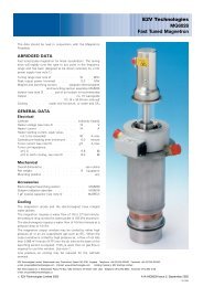
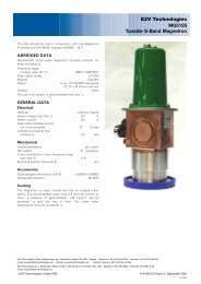
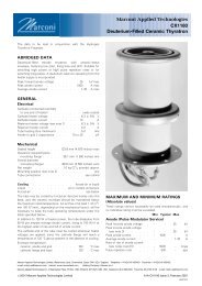
<strong>E2V</strong> <strong>Technologies</strong><strong>MG5349</strong><strong>Tunable</strong> S-<strong>Band</strong> <strong>Magnetron</strong>The data should be read in conjunction with the <strong>Magnetron</strong>Preamble and with British Standard BS9030 : 1971.ABRIDGED DATAMechanically tuned pulse magnetron intended primarily forlinear accelerators.Frequency range . . . . . . 2992 to 3001 MHzPeak output power . . . . . . . . . . 3.1 MWMagnet . . . . . . . . . electromagnet MG6053Output . . . . . . . . . . . to no. 10 waveguide(72.140 x 34.04 mm internal)Isolator . . . . . . . . . . the use of an isolator isrecommended, see note 7Cooling . . . . . . . . . . . . . . . waterGENERALElectricalCathode . . . . . . . . . . . . indirectly heatedHeater voltage (see note 1) . . . . . . 14 VHeater current at 14 V . . . . . . . . 8.0 AHeater starting current, peak value,not to be exceeded . . . . . . . . 20 A maxCathode pre-heating time (minimum) . . . 10 minMechanicalOverall dimensions . . . . . . . . . . . see outlineNet weight . . . . . . . . . . . . 7.3 kg approxTuner revolutions to cover frequencyrange (see note 2) . . . . . . . . . 4 approxMethod of mounting . . . . . . . . . . see note 3Mounting position (see note 4) . . . . . . . . . anyCoolingThe magnetron is water cooled and has an integral waterjacket. The recommended water flow is 5 litres per minute ormore; a pressure of approximately 1.25 kg/cm 2 will benecessary to give this rate of flow. The outlet watertemperature must not exceed 50 8C.The cooling fins on the cathode stem must be cooled by an airflow of at least 0.28 m 3 /min.<strong>E2V</strong> <strong>Technologies</strong> Limited, Waterhouse Lane, Chelmsford, Essex CM1 2QU England Telephone: +44 (0)1245 493493 Facsimile: +44 (0)1245 492492e-mail: enquiries@e2vtechnologies.com Internet: www.e2vtechnologies.com Holding Company: <strong>E2V</strong> Holdings Limited<strong>E2V</strong> <strong>Technologies</strong> Inc. 4 Westchester Plaza, PO Box 1482, Elmsford, NY10523-1482 USA Telephone: (914) 592-6050 Facsimile: (914) 592-5148e-mail: enquiries@e2vtechnologies.us# <strong>E2V</strong> <strong>Technologies</strong> Limited 2002 A1A-<strong>MG5349</strong> Issue 2, October 2002181/6395
MAXIMUM AND MINIMUM RATINGS(Absolute values)These ratings cannot necessarily be used simultaneously, andno individual rating should be exceeded.Min MaxMagnetic field (see note 5) . . 100.0 165.0 mT1000 1650 gaussHeater voltage (see note 1) . . . – 14 VHeater starting current (peak) . . – 20 AAnode voltage (peak) . . . . . – 52 kVAnode current (peak) . . . . 60 120 AInput power (mean) . . . . . . – 8.0 kWPulse duration . . . . . . . . – 5.0 msRate of rise of voltage pulse(see note 6) . . . . . . . . – 120 kV/msOutlet water temperature . . . . – 50 8CVSWR at the output coupler(see note 7) . . . . . . . . – 1.5:1Pressurising of waveguide(see note 8) . . . . . . . . – 3.1 kg/cm 2 gTYPICAL OPERATIONOperational ConditionsMagnetic field . . . . . . . . . . 160.0 + 0.5 mT1600 + 5 gaussHeater voltage . . . . . . . . . . . 0 VAnode current (peak) . . . . . . . . 115 APulse duration . . . . . . . . . . . 4.0 msPulse repetition rate . . . . . . . . 325 ppsRate of rise of voltage pulse . . . . . 120 kV/msTypical PerformanceAnode voltage (peak) . . . . . . . . 49.8 kVOutput power (peak) . . . . . . . . . 3.1 MWOutput power (mean) . . . . . . . . 4.0 kWFrequency drift . . . . . . . . . . . . see note 9TEST CONDITIONS AND LIMITSThe magnetron is tested to comply with the following electricalspecification.Test ConditionsMagnetic field (see note 5) . . . . . . 160.0 + 0.5 mT1600 + 5 gaussHeater voltage (for test) . . . . . . . . 0 VAnode current (peak) . . . . . . . . 115 APulse repetition rate . . . . . . . . 250 ppsPulse duration . . . . . . . . . . . 4.0 msVSWR at the output coupler . . . . . . 1.1:1Rate of rise of voltage pulse (see note 6) . 120 kV/msLimitsMin MaxAnode voltage (peak) . . . . 46 52 kVOutput power (peak)(see note 10) . . . . . . . 3.0 – MWFrequency (see notes 11 and 12):lower end of tuning range . . . – 2992 MHzupper end of tuning range . . 3001 – MHzRF bandwidth at 1 / 4 power . . . – 1.5 MHzFrequency pulling(VSWR not less than 1.5:1) . . – 7.0 MHzStability (see note 13) . . . . . – 0.5 %Heater current . . . . . . . . . . . . see note 14LIFE TESTThe quality of all production is monitored by the randomselection of tubes which are then life-tested under TypicalOperation Conditions. If the tube is to be operated underconditions other than those specified herein, <strong>E2V</strong> <strong>Technologies</strong>should be consulted to verify that the life of the magnetron willnot be impaired.End of Life Criteria(Under the test conditions specified above)Output power (peak) . . . . . . . . . 2.7 MW minRF bandwidth at 1 / 4 power . . . . . . . 1.2 MHz maxFrequency . . . . . . . . . within test limits above.NOTES1. With no anode input power.The heater voltage must be reduced within 5 secondsafter the application of HT according to the scheduleshown on page 3.The magnetron heater must be protected against arcingby the use of a minimum capacitance of 4000 pFshunted across the heater directly at the input terminals;in some cases a capacitance as high as 2 mF may benecessary depending on the equipment design. Forfurther details see the <strong>Magnetron</strong> Preamble.2. The tuner mechanism is driven by means of the threethreaded holes in the tuner knob (see outline) via aflexible drive. The minimum torque required is 0.7 kgcm;the torque applied must not exceed 5.0 kg-cm.3. It is recommended that the magnetron is mounted in theelectromagnet by flange B so that the external polepieceis in contact with the electromagnet poleface. Careshould be taken in mounting the electromagnet, so thatno mechanical stress is applied to the magnetron stemprotruding through the electromagnet poleface.4. To minimise frequency deviation when the magnetron isrotated about a horizontal axis, this axis should beparallel to the axis of the tuner.5. The magnetron is designed for use with anelectromagnet type MG6053 which can be supplied ifrequired. The north seeking poleface of the magnetmust be adjacent to the magnetron anode face which isopposite the cathode stem. The axis of the field is in linewith the axis of the anode and is at right angles to the Hplane of the system waveguide. The user is invited toconsult <strong>E2V</strong> <strong>Technologies</strong> on the choice ofelectromagnets.6. Defined as the steepest tangent to the leading edge ofthe voltage pulse above 80% amplitude. Anycapacitance in the viewing system must not exceed6.0 pF.7. It is recommended that the magnetron should beisolated from the load by means of an isolator ofapproved design. Information on the characteristics of asuitable isolator may be obtained from <strong>E2V</strong><strong>Technologies</strong>.8. At the maximum pressure of 3.1 kg/cm 2 gauge themaximum leakage will be such that with an enclosedvolume of 1 litre the pressure will not drop by more than70 kPa in 7 days.<strong>MG5349</strong>, page 2# <strong>E2V</strong> <strong>Technologies</strong>
9. The frequency of the magnetron will vary during the first30 seconds after the application of anode voltage.Typically the frequency will be 1.0 MHz high 5 secondsafter switching on HT and 0.2 MHz high 60 secondsafter switching on.10. The maximum variation of peak output power when themagnetron is rotated through 3608 around any axis ofthe magnetron will not be greater than 4%.11. With a water flow rate 5.0 litres per minute. Otherfrequency ranges can be supplied on request.12. The maximum variation of frequency when themagnetron is rotated through 3608 around any axis ofthe magnetron will not be greater than 0.7 MHz.13. With the magnetron operating into a VSWR of 1.15:1.Pulses are defined as missing when the RF energy levelis less than 70% of the normal energy level in a 0.5%frequency range. Missing pulses are expressed as apercentage of the number of input pulses applied duringthe period of observation after a period of 10 minutesoperation.14. Measured with heater voltage of 14 V and no anodeinput power, the heater current limits are 7.0 Aminimum, 9.0 A maximum.HEATER VOLTAGE REDUCTIONSCHEDULEHEATER VOLTAGE (V)161412108642UPPER LIMITLOWER LIMIT6463A00 1.0 2.0 3.0 4.0 5.0MEAN INPUT POWER (kW)RECOMMENDED PARAMETERS FOR VARIOUS POWER LEVELSMAGNETIC FIELD (GAUSS)1100 1200 1300 1400 1500 16003.5MAGNETIC FIELD (mT)110 120 130 140 150 1606493A3.02.5OUTPUT POWER (MW)2.01.51.0NORMALOPERATINGCONDITIONS30 35 40 45 50 55ANODE VOLTAGE (kV)75 80 90 100 110 115ANODE CURRENT (A)73 1 / 2 73 72 71 0FREQUENCY CHANGE (MHz)# <strong>E2V</strong> <strong>Technologies</strong> <strong>MG5349</strong>, page 3
OUTLINE (All dimensions without limits are nominal)6462AABCD1E1FGH1JKSEE NOTE 1LFLANGE ‘B’NM1P1Q1R3 HOLES 10-32 UNF-2Bx S DEEPEQUISPACED ON T PCDSEE NOTE 21UUHF COAX CONNECTORSEE NOTE 3WATER JACKET CONNECTORSTHREADED 1 / 4 " BSPVZX1YW<strong>MG5349</strong>, page 4# <strong>E2V</strong> <strong>Technologies</strong>
6464AAARefMillimetres1ACAD22.58AHAJDetail of RF Output Flange22.581 HOLE 1AGSEE NOTE 41 HOLE 1ABSEE NOTE 44 HOLES 1AEON AF PCDSEE NOTE 58 HOLES 1AKEQUISPACED ON AL PCDSEE NOTE 6Outline Notes1. The tolerance on this dimension applies only to the tunerdrive.2. Positional tolerance 0.05 mm diameter.3. Heater-cathode connector is a UHF 50 O coaxial socket; thecorresponding plug is MIL STD PL259 with PTFE insulator.The cathode connection is the outer shell of the socket.4. Positional tolerance 0.5 mm diameter.5. The 4 holes will clear studs 6.35 mm diameter spaced asshown on 139.7 mm pitch circle diameter and within0.127 mm of their normal positions, with the magnetronlocated by dowel pins 7.80 mm diameter and 6.22 mmdiameter spaced 139.700 + 0.051 mm apart.6. Positional tolerance 0.15 mm diameter.A 243.0 maxB 210.0 max6.30 maxC5.00 minD 6.35 + 0.15E 133.5 + 1.5F 92.0 + 0.1G 105.0 + 5.03.30 maxH3.05 minJ 38.0 + 0.5K 135.75 + 0.50L 90.0 maxM 88.0 maxN 35.0 + 1.0P 95.0 maxQ 106.0 maxR 42.0 maxS 6.5 minT 19.05U 41.5 maxV 12.5 + 0.5W 30.0 minX 113.0 maxY 93.0 maxZ 30.0 maxAA 260.0 maxAB 8.0 + 0.05152.40 maxAC152.15 minAD 139.7AE 8.0 + 0.1AF 139.7AG 6.40 + 0.05AH 54.0 maxAJ 100.0 maxAK 6.4 + 0.1AL 120.65# <strong>E2V</strong> <strong>Technologies</strong> <strong>MG5349</strong>, page 5
HEALTH AND SAFETY HAZARDS<strong>E2V</strong> <strong>Technologies</strong> magnetrons are safe to handle and operate,provided that the relevant precautions stated herein areobserved. <strong>E2V</strong> <strong>Technologies</strong> does not accept responsibility fordamage or injury resulting from the use of electronic devices itproduces. Equipment manufacturers and users must ensurethat adequate precautions are taken. Appropriate warninglabels and notices must be provided on equipmentsincorporating <strong>E2V</strong> <strong>Technologies</strong> devices and in operatingmanuals.High VoltageEquipment must be designed so that personnel cannot comeinto contact with high voltage circuits. All high voltage circuitsand terminals must be enclosed and fail-safe interlock switchesmust be fitted to disconnect the primary power supply anddischarge all high voltage capacitors and other stored chargesbefore allowing access. Interlock switches must not bebypassed to allow operation with access doors open.RF RadiationPersonnel must not be exposed to excessive RF radiation. AllRF connectors must be correctly fitted before operation so thatno leakage of RF. energy can occur and the RF output must becoupled efficiently to the load. It is particularly dangerous tolook into open waveguide or coaxial feeders while the device isenergised. Screening of the cathode sidearm of high powermagnetrons may be necessary.X-Ray RadiationHigh voltage magnetrons emit a significant intensity of X-raysnot only from the cathode sidearm but also from the outputwaveguide. These rays can constitute a health hazard unlessadequate shielding for X-ray radiation is provided. This is acharacteristic of all magnetrons and the X-rays emittedcorrespond to a voltage much higher than that of the anode.Whilst <strong>E2V</strong> <strong>Technologies</strong> has taken care to ensure the accuracy of the information contained herein it accepts no responsibility for the consequences of any usethereof and also reserves the right to change the specification of goods without notice. <strong>E2V</strong> <strong>Technologies</strong> accepts no liability beyond that set out in its standardconditions of sale in respect of infringement of third party patents arising from the use of tubes or other devices in accordance with information contained herein.<strong>MG5349</strong>, page 6Printed in England# <strong>E2V</strong> <strong>Technologies</strong>