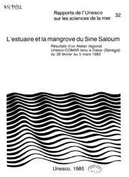
Sea Level Measurement <strong>and</strong> Interpretati<strong>on</strong>An internati<strong>on</strong>al working group was set up in the late1980s by the Internati<strong>on</strong>al Associati<strong>on</strong> for the PhysicalSciences of the Ocean, under its Commissi<strong>on</strong> <strong>on</strong> MeanSea Level <strong>and</strong> Tides, to recommend a strategy for thegeodetic fixing of tide gauge bench marks. Theseresulted in the ‘Carter reports’ (Carter et al., 1989;Carter, 1994). The following secti<strong>on</strong>s provide a summary<strong>and</strong> describe recent developments. The reader isreferred to Neilan et al. (1998) <strong>and</strong> Bevis et al. (2002)for further details.a4.4.2 GPS MeasurementsOver the past decade, the GPS technique has developedrapidly to the extent that it is of fundamentalimportance to many areas of geophysical re<strong>sea</strong>rch (seelinks documented <strong>on</strong> the PSMSL training web page).The Internati<strong>on</strong>al GNSS Service (IGS) receives datafrom a global network of GPS stati<strong>on</strong>s <strong>and</strong> producesinformati<strong>on</strong> <strong>on</strong> the orbits of the GPS satellites whichis significantly more precise than the ephemeridesroutinely transmitted by the satellites themselves. Thisinformati<strong>on</strong> is employed by re<strong>sea</strong>rchers to produce precisepositi<strong>on</strong>ing computati<strong>on</strong>s. GPS data from the IGSnetwork are archived at the IGS Central Bureau.bIdeally, all tide gauge sites should be equipped witha permanent c<strong>on</strong>tinuous receiver (CGPS). However,in practice, the financial resources required are oftenlarge. Many countries adopt the procedure of installingpermanent GPS receivers at strategic tide gauges<strong>and</strong> then densifying the network with regular GPScampaign <strong>measurement</strong>s (Neilan et al., 1998). Thereis clearly an advantage in c<strong>on</strong>centrating CGPS workat sites with l<strong>on</strong>g durati<strong>on</strong> PSMSL RLR mean <strong>sea</strong> <strong>level</strong>records. The GLOSS Implementati<strong>on</strong> Plan refers to thisset as the GLOSS L<strong>on</strong>g-Term Trends (GLOSS-LTT) network.The campaigns can then c<strong>on</strong>centrate <strong>on</strong> othertide gauges in the network for which the records areshorter. The exact mix between permanent <strong>and</strong> campaignGPS tide gauges will change as the cost of GPSreceivers c<strong>on</strong>tinues to decrease.For studies involving <strong>sea</strong> <strong>level</strong>, it is recommended thata dual-frequency CGPS receiver should be installeddirectly at the tide gauge so that it m<strong>on</strong>itors anymovement of the TGBM. If the receiver is placedexactly at the TGBM, then the GPSBM <strong>and</strong> theTGBM will coincide, eliminating the need for <strong>level</strong>lingbetween the two benchmarks. The TGBM is then thefundamental point that is geocentrically located bythe GPS <strong>measurement</strong>s <strong>and</strong> to which all the <strong>sea</strong> <strong>level</strong><strong>measurement</strong>s are related. In practice, tide gauge sitesare not always ideal for making GPS <strong>measurement</strong>s.This may be due to obscured sky visibility, excessivemultipath transmissi<strong>on</strong>s or because of radio interference,in which case a site should be chosen that is asclose as possible to the tide gauge. Ideally, this shouldbe within a few hundred metres.Figure 4.3 Alternative forms of GPS mounting(a) a Norwegian tide gauge with GPS antenna mounted<strong>on</strong> an adjacent platform;(b) GPS antenna <strong>on</strong> a pillar, as recommended by theCGPS@TG group (http://soest.hawaii.edu/cgps_tg).32IOC <str<strong>on</strong>g>Manual</str<strong>on</strong>g>s <strong>and</strong> Guides No 14 vol IV
Sea Level Measurement <strong>and</strong> Interpretati<strong>on</strong>The GPSBM <strong>and</strong> GPS antenna need to be <strong>level</strong>led to theTGBM at least annually. Experience has shown that theseregular <strong>level</strong>ling c<strong>on</strong>necti<strong>on</strong>s are often neglected overthe years. This is particularly true if the distance involvedis more than a few hundred metres <strong>and</strong> it can never beassumed that even relatively close sites are not moving differentiallyat a rate of around 1 mm per year.Whilst the detailed procedures for making GPS <strong>measurement</strong>sat tide gauges are still the subject of re<strong>sea</strong>rch,<strong>and</strong> are still being discussed by the IGS/PSMSL TechnicalCommittee, there is already a general agreement <strong>on</strong>the main principles. Using GPS for measuring horiz<strong>on</strong>talcrustal movements is now well established. However,for the vertical comp<strong>on</strong>ent, measuring l<strong>and</strong> movementsto better than l mm per year is still a major challenge.Re<strong>sea</strong>rch is c<strong>on</strong>tinuing <strong>on</strong> modelling the wet comp<strong>on</strong>entof the troposphere, modelling the deformati<strong>on</strong> of theEarth due to surface loading by ocean tides, coastal <strong>and</strong>global <strong>sea</strong> <strong>level</strong>s, atmospheric variati<strong>on</strong>s <strong>and</strong> hydrologicalloading. A major re<strong>sea</strong>rch challenge lies in realizing <strong>and</strong>maintaining a global reference frame that is sufficientlystable for measuring vertical movements to an accuracy ofa few tenths of a millimetre per year (Teferle et al., 2006;Ge et al., 2005).In some countries, a sec<strong>on</strong>d CGPS receiver is beinginstalled a few kilometres inl<strong>and</strong> at a site which hasa good multipath envir<strong>on</strong>ment <strong>and</strong> a better c<strong>on</strong>necti<strong>on</strong>to bedrock. While such a site might be better fortesting geophysical models of vertical crustal movements,it cannot be c<strong>on</strong>sidered to be a substitute forthe CGPS receiver at the tide gauge. The difficulty <strong>and</strong>cost of <strong>level</strong>ling over distances of a few kilometres aresignificant.Many of the practical issues involved with installing CGPSat tide gauges are reviewed in the case studies <strong>on</strong> the website http://soest.hawaii.edu/cgps_tg <strong>and</strong> also in the associatedpaper by Bevis et al. (2002).4.4.3 DORIS MeasurementsDORIS is a French tracking system based <strong>on</strong> a spacesegment placed <strong>on</strong> an orbiting satellite <strong>and</strong> a networkof ground stati<strong>on</strong>s distributed worldwide. Initially it wasc<strong>on</strong>ceived to improve our knowledge of satellite orbits, but<strong>on</strong>ce these were determined to a sufficient accuracy, thesystem could be used to locate the geocentric positi<strong>on</strong> ofthe receiving antenna at each ground stati<strong>on</strong>.DORIS is a <strong>on</strong>e-way Doppler uplink system in which theground stati<strong>on</strong>s broadcast c<strong>on</strong>tinuously <strong>on</strong> two frequencies,2 GHz <strong>and</strong> 400 MHz, in order to correct Doppler<strong>measurement</strong>s for i<strong>on</strong>ospheric delay. Each beac<strong>on</strong> includesan ultra-stable oscillator <strong>and</strong> meteorological sensors tocorrect the data for tropospheric delay. The space segmentis made up of the set of satellites carrying the DORIS<strong>on</strong>board receiver. Six DORIS receivers are currently working<strong>on</strong>board the TOPEX–Poseid<strong>on</strong>, Jas<strong>on</strong>, Envisat <strong>and</strong> theEarth observati<strong>on</strong> satellites Spot-2, Spot-4 <strong>and</strong> Spot-5.The DORIS technique has proved to be capable of m<strong>on</strong>itoringvertical l<strong>and</strong> movements with the following precisi<strong>on</strong>.In the early 1990s, when <strong>on</strong>ly <strong>on</strong>e satellite was inorbit, the precisi<strong>on</strong> of absolute positi<strong>on</strong>ing was about 4cm. This precisi<strong>on</strong> was regularly improved as new satelliteswere launched, <strong>and</strong> reached around 1.5 cm accuracy. Thesix satellites now in orbit provide sub-centimetre precisi<strong>on</strong>in absolute positi<strong>on</strong>ing, <strong>and</strong> vertical l<strong>and</strong> velocities with aprecisi<strong>on</strong> of 1 mm per year.The current network of DORIS ground stati<strong>on</strong>s offersa homogeneous distributi<strong>on</strong> over the c<strong>on</strong>tinents <strong>and</strong>oceans, with about 60 beac<strong>on</strong>s deployed in some 30countries. It is planned to increase this distributi<strong>on</strong> throughthe framework of the Internati<strong>on</strong>al DORIS Service. SomeDORIS ground stati<strong>on</strong>s have been co-located at stati<strong>on</strong>spossessing other geodetic instrumentati<strong>on</strong>. For example:7 at Satellite Laser Ranging sites; 28 at GPS sites; 9 at VLBIsites; <strong>and</strong> 14 at tide gauges.4.4.4 Absolute Gravity MeasurementsThe principle of the absolute gravimeter is the <strong>measurement</strong>of the accelerati<strong>on</strong> of a mass in free fall (or ri<strong>sea</strong>nd fall) in a vacuum using a laser length st<strong>and</strong>ard <strong>and</strong>a rubidium-frequency time st<strong>and</strong>ard. The mass used inthe gravimeter is a retro-reflector that forms <strong>on</strong>e end ofa laser interferometer. By counting interference fringes asthe mass falls, the positi<strong>on</strong> of the mass is measured <strong>and</strong>determined as a functi<strong>on</strong> of time. C<strong>on</strong>siderable effort hasbeen put into reducing or eliminating various sources ofsystematic error in the instrument. The latest transportableabsolute gravimeter is the FG5 instrument (Niebauer et al.1995). The specificati<strong>on</strong>s for this instrument are a precisi<strong>on</strong>of better than 1 mgal <strong>and</strong> an accuracy of 2 µgal (N.B.1 gal = 1 cm/sec 2 , so 1 µgal = 10 nm/sec 2 . A microgal(mgal) corresp<strong>on</strong>ds roughly to 5 mm of crustal movement).For further details of the absolute gravimeter <strong>and</strong> abibliography of published papers see the Micro-g website(http://www.microgsoluti<strong>on</strong>s.com/).The gravity value at a site is found by making repeateddrops of the test mass for typically <strong>on</strong>e or two days<strong>and</strong> making correcti<strong>on</strong>s for the gravitati<strong>on</strong>al variati<strong>on</strong>scaused by tides, earth tides <strong>and</strong> atmospheric pressure.Various intercomparis<strong>on</strong> experiments have been madebetween different FG5 absolute gravimeters; typicallythey agree at the 1–2 µgal <strong>level</strong> (Sasagawa et al., 1995).At good sites, <strong>measurement</strong>s made over a number ofyears show repeatability of about 2 µgal.In free air the gravity gradient at the Earth’s surface, is3 mgal/cm. In practice, for crustal deformati<strong>on</strong> work,since a large area of the Earth’s surface is usually displacedsimultaneously, the measured gravity change isabout 2 µgal/cm. Thus, it can be seen that absoluteIOC <str<strong>on</strong>g>Manual</str<strong>on</strong>g>s <strong>and</strong> Guides No 14 vol IV33