Manual on sea level measurement and ... - unesdoc - Unesco
Manual on sea level measurement and ... - unesdoc - Unesco
Manual on sea level measurement and ... - unesdoc - Unesco
- No tags were found...

Create successful ePaper yourself
Turn your PDF publications into a flip-book with our unique Google optimized e-Paper software.
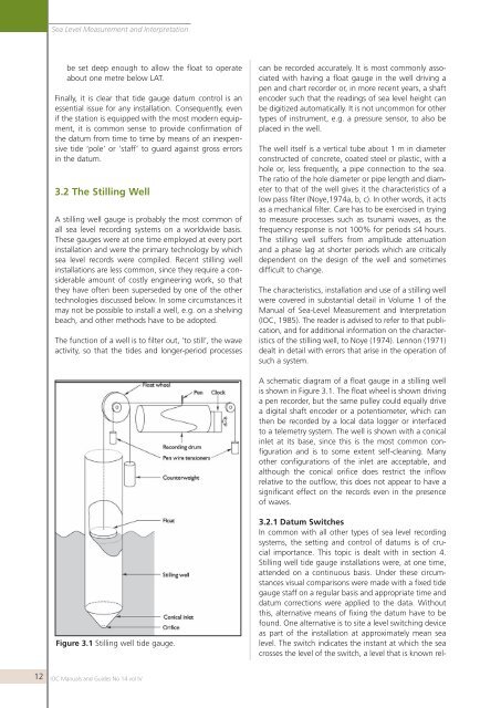
Sea Level Measurement <strong>and</strong> Interpretati<strong>on</strong>be set deep enough to allow the float to operateabout <strong>on</strong>e metre below LAT.Finally, it is clear that tide gauge datum c<strong>on</strong>trol is anessential issue for any installati<strong>on</strong>. C<strong>on</strong>sequently, evenif the stati<strong>on</strong> is equipped with the most modern equipment,it is comm<strong>on</strong> sense to provide c<strong>on</strong>firmati<strong>on</strong> ofthe datum from time to time by means of an inexpensivetide ‘pole’ or ‘staff’ to guard against gross errorsin the datum.3.2 The Stilling WellA stilling well gauge is probably the most comm<strong>on</strong> ofall <strong>sea</strong> <strong>level</strong> recording systems <strong>on</strong> a worldwide basis.These gauges were at <strong>on</strong>e time employed at every portinstallati<strong>on</strong> <strong>and</strong> were the primary technology by which<strong>sea</strong> <strong>level</strong> records were compiled. Recent stilling wellinstallati<strong>on</strong>s are less comm<strong>on</strong>, since they require a c<strong>on</strong>siderableamount of costly engineering work, so thatthey have often been superseded by <strong>on</strong>e of the othertechnologies discussed below. In some circumstances itmay not be possible to install a well, e.g. <strong>on</strong> a shelvingbeach, <strong>and</strong> other methods have to be adopted.The functi<strong>on</strong> of a well is to filter out, ‘to still’, the waveactivity, so that the tides <strong>and</strong> l<strong>on</strong>ger-period processescan be recorded accurately. It is most comm<strong>on</strong>ly associatedwith having a float gauge in the well driving apen <strong>and</strong> chart recorder or, in more recent years, a shaftencoder such that the readings of <strong>sea</strong> <strong>level</strong> height canbe digitized automatically. It is not uncomm<strong>on</strong> for othertypes of instrument, e.g. a pressure sensor, to also beplaced in the well.The well itself is a vertical tube about 1 m in diameterc<strong>on</strong>structed of c<strong>on</strong>crete, coated steel or plastic, with ahole or, less frequently, a pipe c<strong>on</strong>necti<strong>on</strong> to the <strong>sea</strong>.The ratio of the hole diameter or pipe length <strong>and</strong> diameterto that of the well gives it the characteristics of alow pass filter (Noye,1974a, b, c). In other words, it actsas a mechanical filter. Care has to be exercised in tryingto measure processes such as tsunami waves, as thefrequency resp<strong>on</strong>se is not 100% for periods ≤4 hours.The stilling well suffers from amplitude attenuati<strong>on</strong><strong>and</strong> a phase lag at shorter periods which are criticallydependent <strong>on</strong> the design of the well <strong>and</strong> sometimesdifficult to change.The characteristics, installati<strong>on</strong> <strong>and</strong> use of a stilling wellwere covered in substantial detail in Volume 1 of the<str<strong>on</strong>g>Manual</str<strong>on</strong>g> of Sea-Level Measurement <strong>and</strong> Interpretati<strong>on</strong>(IOC, 1985). The reader is advised to refer to that publicati<strong>on</strong>,<strong>and</strong> for additi<strong>on</strong>al informati<strong>on</strong> <strong>on</strong> the characteristicsof the stilling well, to Noye (1974). Lenn<strong>on</strong> (1971)dealt in detail with errors that arise in the operati<strong>on</strong> ofsuch a system.A schematic diagram of a float gauge in a stilling wellis shown in Figure 3.1. The float wheel is shown drivinga pen recorder, but the same pulley could equally drivea digital shaft encoder or a potentiometer, which canthen be recorded by a local data logger or interfacedto a telemetry system. The well is shown with a c<strong>on</strong>icalinlet at its base, since this is the most comm<strong>on</strong> c<strong>on</strong>figurati<strong>on</strong><strong>and</strong> is to some extent self-cleaning. Manyother c<strong>on</strong>figurati<strong>on</strong>s of the inlet are acceptable, <strong>and</strong>although the c<strong>on</strong>ical orifice does restrict the inflowrelative to the outflow, this does not appear to have asignificant effect <strong>on</strong> the records even in the presenceof waves.Figure 3.1 Stilling well tide gauge.3.2.1 Datum SwitchesIn comm<strong>on</strong> with all other types of <strong>sea</strong> <strong>level</strong> recordingsystems, the setting <strong>and</strong> c<strong>on</strong>trol of datums is of crucialimportance. This topic is dealt with in secti<strong>on</strong> 4.Stilling well tide gauge installati<strong>on</strong>s were, at <strong>on</strong>e time,attended <strong>on</strong> a c<strong>on</strong>tinuous basis. Under these circumstancesvisual comparis<strong>on</strong>s were made with a fixed tidegauge staff <strong>on</strong> a regular basis <strong>and</strong> appropriate time <strong>and</strong>datum correcti<strong>on</strong>s were applied to the data. Withoutthis, alternative means of fixing the datum have to befound. One alternative is to site a <strong>level</strong> switching deviceas part of the installati<strong>on</strong> at approximately mean <strong>sea</strong><strong>level</strong>. The switch indicates the instant at which the <strong>sea</strong>crosses the <strong>level</strong> of the switch, a <strong>level</strong> that is known rel-12IOC <str<strong>on</strong>g>Manual</str<strong>on</strong>g>s <strong>and</strong> Guides No 14 vol IV