Masoneilan Noise Control Manual - ICEWeb
Masoneilan Noise Control Manual - ICEWeb
Masoneilan Noise Control Manual - ICEWeb
- No tags were found...

Create successful ePaper yourself
Turn your PDF publications into a flip-book with our unique Google optimized e-Paper software.
2. Aerodynamic <strong>Noise</strong>Prediction (cont.)2.3 Additional CommentsExamples of the use of the prediction methods are shownin detail in the respective standards. These examples maybe used to verify a computer program.The IEC standard also provides for prediction for proprietarylow noise trim designs and other valve configurationsnot specifically covered by the standard. The manufactureris required to incorporate additional changes in soundpressure level as a function of travel and/or pressure ratio,in addition to the sound pressure level obtained by usingthe appropriate clauses applying to valves with standardtrim. <strong>Masoneilan</strong> has accomplished this requirement in ourvalve sizing and selection computer program.NomenclatureA = flow areaC v = valve capacityc = sound speed of gasc p = sound speed of pipingd p = outlet pipe inner diameterd v = outlet valve inner diameterd vc = trim jet vena contracta diameterF d = valve style modifierF L = pressure recovery coefficientf = sound frequencyf o = acoustic-structural Coincident Frequencyf p = flow peak frequencyf r = pipe ring frequencyL e = expander and pipe flow noise soundpressurelevel, A-weighted and 1 meterfrom the pipe wallL g = pipe Mach number correction factorL pAe = A-weighted sound-pressure level•m = mass flow rateL pAe.1m = A-weighted sound-pressure level,1 meter from pipe wallL pi = pipe internal sound-pressure levelM = Mach numberMw = molecular weight of gasp = pressurep a = actual pressure outside pipep s = standard pressure outside pipe(1 atmosphere)R = universal gas constantT = gas temperatureTL = pipe transmission lossTL fr = pipe transmission loss at ring frequencyt p = pipe wall thicknessU = velocityW a = sound powerW m = stream power of mass flowGreekγ = ratio of specific heatsη = acoustical efficiency factorρ = gas densitySubscripts1 = upstream of valve or vena contracta2 = downstream of valve or vena contractae = expanderv = valve outletvc = vena contractaI = Regime I8 OZ3000 01/02
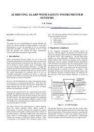
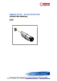
3. Aerodynamic <strong>Control</strong> Valve<strong>Noise</strong> Reduction3.1 MethodsReduction of control valve aerodynamic noise can beachieved by either source treatments (preventing the noisegeneration) or path treatments (pipe insulation, silencers,or increasing pipe schedule). Source treatment oftenbecomes the preferable method. Sound, once generated,propagates virtually unattenuated in downstream pipe.In addition, as discussed in the Appendix, very high soundlevels inside piping systems can damage the pipe andmechanical components located downstream by inducingexcessive vibration.3.1.1. Source TreatmentThe generation of noise can be controlled byusing trim components specially designed forlow noise production. There are basically twomethods employed in reducing noise generated inthe valve trim:1. Use of Small, Properly Spaced Fluid JetsThe size of the fluid jets affects noise generationin three ways. First, by reducing the size of thefluid jets (and consequently the size of theeddies), the efficiency of conversion betweenmechanical and acoustical power is reduced.Second, the smaller eddies shift the acousticenergy generated by the flow to the higherfrequency regions where transmission throughthe pipe walls is sharply reduced. Third, thehigher frequency sound, if raised above 10000 Hz,is de-emphasized by both the A-weighting filternetwork and the human ear.The spacing of the fluid jets affects the locationof the point downstream at which the fluid jetsmutually interfere. The mutual interaction ofthe fluid jets at the proper location downstreamthereby reduces the shock-eddy interaction that islargely responsible for valve noise under criticalflow conditions. This factor further reducesacoustical efficiency.2. Adiabatic Flow with FrictionThe principle of “Adiabatic Flow with Friction” is toreduce pressure much like the pressure losswhich occurs in a long pipeline. This effect is producedby letting the fluid pass through a numberof restrictions, providing a tortuous flow patterndissipating energy through high headloss ratherthan through shock waves.The flow area of the valve trim is graduallyincreased toward the downstream section.This compensates for expansion of the gas withpressure loss and ensures a nearly constant fluidvelocity throughout the complete throttling process.Enthalpy hS0Ideal Adiabatic Flow with FrictionMultistepInternalFriction DeviceEntropyS0 2ConventionalSingle OrificeValveSFigure 2As shown on Figure 2, in conventional orifice typevalves, internal energy is converted into velocity(kinetic energy). This results in a sharp decreasein enthalpy. Downstream turbulence accompaniedby shock waves, reconverts this velocity intothermal energy with a permanent increase inentropy level (corresponding to the pressurechange P 1 -P 2 ).These same shock waves arethe major source of undesirable throttling noise. Ina LO-DB valve, however, the velocity change isminimized and the enthalpy level remains nearlyconstant.Most <strong>Masoneilan</strong> LO-DB valves use both of thepreviously mentioned methods to limit noisegeneration to the minimum levels possible. Whencontrolling noise using source treatments, suchas LO-DB valves, it is imperative that the fluidvelocity at the valve outlet is limited to avoidregenerating noise at this potential source.Low noise valves are inherently quieter (less efficientnoise generators), due to their specialtrim designs. The noise generated by the outlet,if not properly limited, can easily dominateover the noise generated by the trim, renderingthe low noise trim virtually ineffective. There are twomethods used to control outlet velocity. First, thedownstream pressure can be increased by using<strong>Masoneilan</strong> LO-DB cartridges and expansionplates. This method, from Bernoulli’s principle,decreases the velocity at the valve outlet byincreasing the pressure immediately downstreamof the valve. The second method is simply tochoose a valve size that is adequate to ensure theproper outlet velocity.OZ3000 01/029
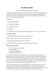
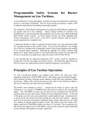
3. Aerodynamic <strong>Control</strong> Valve<strong>Noise</strong> Reduction (cont.)device, the result is a much quieter system operation.Also, because the intermediate pressurebetween the valve and the restrictor is increased,sonic valve outlet velocity and its associatednoise generation are avoided. This often facilitatesthe use of smaller valves, typically resultingin total system cost savings of 50%. When usedwith conventional valves, up to 20 dBA noisereduction can be achieved at modest cost.Thesavings over a valve alone installation are attributedto use of smaller (because of reduced outletvelocity), relatively low cost valves such as theCamflex ® and Varimax . With LO-DB valves, over30 dBA noise reduction can be achieved with thesame sizable cost advantages. These devices areparticularly effective at pressure ratios of 3 or morewhere the maximum advantage of multiple-stagingeffect can be realized.21000 Series with LO-DB TrimThis valve model fills the moderate cost, moderatenoise reduction category of the product line.Operated flow-to-open (FTO), it produces noiselevels approximately 16-19 dBA lower than conventionalvalves. The LO-DB trim is based on<strong>Masoneilan</strong>'s multiple-orifice cage concept. It iscompletely interchangeable with other 21000Series parts. A two-stage noise reducing trim isnow available for greater noise reduction.The 21000 LO-DB is the optimum choice for abroad range of process applications due to itssimple construction, tight shutoff, and effectivenoise reduction.2600 Series with LO-DB TrimThis valve is ideally suited to chemical and otherindustries. Its key features include a modularapproach to valve construction that resultsin angle, globe or other configurations, availabilityof numerous body materials, quick change trimand separable flanges. The LO-DB trim basedon <strong>Masoneilan</strong>'s multiple-orifice cage concept,generates up to 12 dBA less noise than conventionalvalves.41000 Series with LO-DB TrimThe 41000 Series control valve can be equippedwith four different efficient noise reduction packageswhich comply with process conditions.These trim packages are directly interchangeablewith conventional construction. These packagesinclude:1. Standard Capacity LO-DB2. High Capacity LO-DB3. Reduced Capacity LO-DB4. Multi-Stage LO-DBThe cage, which is the LO-DB element, has beendesigned using the latest in hole sizing and spacingtechnology from both <strong>Masoneilan</strong> researchand NASA funded programs. Proper hole sizingand spacing prevents jet reconvergence andshock-induced effects, which reduce acousticenergy formation.30000 Series Varimax with LO-DB TrimThe Varimax LO-DB valve provides control of highpressure compressible fluids without the erosion,vibration and high noise levels associated withconventionally designed rotary valves. Becausethe Varimax has relatively large flow passages itis particularly well suited for applications involvinggases. For high pressure ratios, LO-DB cartridgesin the globe adaptor are recommended.The high rangeability 100:1 of this VarimaxLO-DB valve allows wide variations in controlledflow. Operation is stable because the plug isequilibrated. This uniquely balanced plug has nosecondary balancing seal and mounts with astandard seat.72001 Series LO-DBUsing the proven 41000 LO-DB trim design in anangle body configuration, the 72001 Series fabricated,low noise, angle valve provides high flowcapacity with high noise attenuation. Typicalapplications involve gas collection systems, compressorsurge control, and gas-to-flare lines.<strong>Noise</strong> prediction and attenuation are identical withthe 41000 LO-DB Series. Furthermore, an optimalsecond stage cage provides added noisereduction on high pressure drop service whenrequired. The 72001 Series valves are availablewith outlet sizes up to 36" and capacities up to5000 Cv, and with expanded outlet to reducevalve outlet velocity.72003 Series V-LOGUsed on very high pressure ratio applications(usually > 10 to 1), where the 2-stage drilled cagedesign cannot provide acceptable noise levelsand/or some trim velocity limitations are required.The trim design is a brazed stack of overlappingdiscs which form individual tortuous flowpaths. High path flow resistance is achieved byright angle turns with some contractions andexpansions. Because each stack uses individuallaser cut discs, customized staging and flowOZ3000 01/02 11
3. Aerodynamic <strong>Control</strong> Valve<strong>Noise</strong> Reduction (cont.)characteristics can be achieved. The small flowpaths shift sound frequency to increasetransmission losses while area expansion andpath resistance reduce trim velocities anddecrease sound source strength. The V-LOG trimis available in the very large and versatile 72000Series style angle bodies with expanded outletsto reduce valve outlet velocities. Like the 72001Series this product is typically used in large gasline applications, Vent-to-Flare, Soot Blower, andCompressor Recycle.77000 Series LO-DBThis is a specialized valve, of extremely toughconstruction fitted with an effective multiplestagedLO-DB trim. The multi-step labyrinth typeplug and seat ring incorporate Stellite-faced seatingsurfaces which, when coupled with leveragedactuator force, provide tight shutoff. The labyrinthflow pattern, with a large number of steps, resultsin gradual pressure reduction and quiet operation- approximately 20 dBA quieter than conventionalvalves. Perhaps most importantly, the shape ofthe flow passages are designed to preventdeposits and entrapment of solids that may beentrained in the fluid stream. Combined with lowfluid velocity, longer wear is ensured. These plusmany other features make the 77000 Series valveideal for high pressure drop applications, especiallythose involving solid-entrained fluids typicalof drilling rig platforms, where it has achievednotable success.30000 Series Varimaxwith LO-DB Trim2600 Series Valvewith LO-DB Trim21000 Series Valvewith LO-DB Trim41000 Series Valvewith LO-DB Trim41000 Series Valvewith LO-DB Trimand Optional Diffuser41000 Series Double Stagewith LO-DB Trim77000 Series LO-DB Valve 72000 Series LO-DB ValveLO-DB CartridgeLO-DB Expansion Plate12 OZ3000 01/02
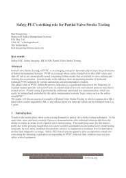
3. Aerodynamic <strong>Control</strong> Valve<strong>Noise</strong> Reduction (cont.)3.3 LO-DB Static Restrictor SelectionP 1Flow DirectionUsed with either conventional or low noise valves, LO-DBcartridges and expansion plates can be an extremely costeffective low noise system.The static restrictor should be sized using valve sizingequations. Normally, the pressure ratio across the restrictorshould be taken as 2 to 1 for initial sizing purposes. Theaddition of a restrictor holds a higher downstream pressureon the control valve, reducing the noise generation of thevalve. A pressure drop of at least 20% of the total pressuredrop should be taken across the valve to assure goodcontrol. If a conventional valve requires a pressure dropof less than 20% to meet the acceptable noise level, aLO-DB valve must be considered.For high system pressure ratios, two or more restrictorsmay be used. For sizing purposes, a pressure ratio of 2 to1 should be taken across each restrictor.3.3.1 Estimation of Sound LevelAerodynamic noise generated by a low noise staticrestrictor (LO-DB cartridge or expansion plate)can be calculated by using the same procedureemployed to estimate low noise control valvenoise level.P 3When a valve and a restrictor are in series, themethod for calculating the overall noise level willvary somewhat depending upon how the valveand restrictor are connected (i.e., reducer orlength of pipe). The following methods are usedto calculate system noise.Case IValve and downstream restrictor(s) are closecoupled by reducer(s).1. Calculate the aerodynamic valve noise for aconventional valve or a low noise valve,using the restrictor inlet pressure as valvedownstream pressure, and pipe wall thicknessand pipe diameter downstream of therestrictor(s).2. Calculate the sound level of the restrictor(s)by using the methods for low noise valves.3. Find the total sound level for the valve andrestrictor(s) combination.a. From the sound levels calculated inSteps 1 and 2, subtract 6 dBA for eachrestrictor downstream of a noise source.The limit of 12 dBA applies with 2 ormore downstream restrictors.b. Determine the final sound level by logarithmicaddition. Logarithmically add theresults above according to Figure 4 toobtain the estimated sound level downstreamof the final restrictor.Note that the close coupling of the valve and LO-DBcartridges and expansion plates results in a lowerpredicted noise level than when separated by pipe.Case IIValve and downstream restrictor(s) are separatedby a length of pipe (not close coupled).1. Calculate the sound level downstream of thefinal restrictor as in Case I.P 22. Calculate the sound level for the controlvalve using restrictor upstream pressure asvalve downstream pressure, and pipe wallthickness and pipe diameter of the connectingpipe. This is the sound level radiated bythe connecting pipe.3. Compare sound levels of the connecting pipeand downstream of the final restrictor. Theconnecting pipe is an effective noise sourcethat should be examined to determine overallsystem performance.3.02.52.01.51.00.5012345678 9 10 12 14 16Figure 4Decibel Difference Between Two Sound Levels dBAdBA to be Added to Largest LevelOZ3000 01/0213
4. Atmospheric Vent Systems4.1 Introduction<strong>Noise</strong> emitted from atmospheric vents, using eitherconventional, low noise valves, or valve-restrictor systemscan be calculated using the procedure below. Sphericalradiation is assumed which reduces noise by 6 dBA foreach doubling of distance. However, at long distances,much lower noise levels would be expected due to atmosphericabsorption and attenuating effects of topography,wind, temperature gradients, and ground effects.LO-DB static resistors (cartridges and plates) used witheither LO-DB or conventional valves, can often providethe most cost effective solution to vent applications.If these systems are used, only the final system soundlevel is considered.4.2 <strong>Noise</strong> Calculation Procedure90˚45˚-5dBA-10dBA135˚-15dBA0dBA0˚VerticalVent StackStep 1Step 2Step 3Calculate the base sound level for a conventionalvalve, low noise valve, or static restrictor by themethods given in the previous sections. However,in each case, use transmission loss, TL, equal tozero. Correct for distance, r, by subtracting 20 logr/3 for distance in feet (or 20 log r for distance inmeters) to obtain the corrected sound level.Correct for DirectivityThe directivity index is important in vent applicationsbecause of the directional nature of highfrequency noise typical of control valve signature.Figure 5 is based on typical average peak frequenciesof 1000 to 4000 Hz. If a silencer is used,the directivity index will change appreciably.Silencers, by design, absorb the high frequency(directional) components from the valve spectralsignature, leaving predominantly low frequencynoise. Consequently, for silencer applications,use one half the directivity index at each angleshown. Add the directivity index to the sound leveldetermined in Step 1.For large distances, make appropriate correctionsfor wind and temperature gradients, topography,and atmospheric absorption, for a specificapplication.5. Hydrodynamic <strong>Noise</strong>5.1 PredictionFigure 5Directivity IndexThe basic sources of hydrodynamic noise include:• Turbulent flow• Flashing• Cavitation• Mechanical vibration resulting from turbulent flow,cavitation, and flashingProblems resulting from high hydrodynamic noise levelsare flashing erosion, cavitation erosion, and combined erosion/corrosion.Unlike aerodynamic noise, hydrodynamicnoise can be destructive even at low levels, thus requiringadditional limitations for good valve application practice.The international standard for control valve hydrodynamicnoise prediction is IEC-534-8-4. The method in thisstandard is based on physics principles, and can beapplied to any valve style. Like the aerodynamic standardthe intended accuracy is plus or minus five decibels.14OZ3000 01/02
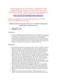
5. Hydrodynamic <strong>Noise</strong> (cont.) incipient is found by use of very high frequencyThe factors used in the calculations are:• F L• X FPressure Recovery, Choked Flow FactorDifferential Pressure Ratiodetection.Flow Curve• X FZ is approximately σ i (not high frequencydetection)K cX FZ• X FZPressure Ratio at Which Cavitation Inception isAcoustically DetectedQσ i (High Freq.)• η FOZ3000 01/02Acoustical Efficiency Factor (Ratio of SoundPower to Stream Power)1x10 -8 for Std. Globe Valve• ∆L F Valve Specific Correction Factor for CavitatingFlowL wi Measured - L wi Calculated• L wi Internal Sound Power• F B Factor to Account for Cavitation of Multi-Component Fluids Having a Range of VaporPressures5.1.1 The graph below depicts a typical liquid flowcurve for a control valve over a wide rangeof pressure drops, with constant inlet pressure.Flow rate is plotted on the vertical axis versus thesquare root of pressure drop. At relatively lowto moderate pressure drop, in the range of fullyturbulent and non-vaporizing flow, flow is proportionalto the square root of pressure drop. Athigh-pressure drop, flow is choked; that is, furtherdecrease of downstream pressure does not resultin an increase in flow rate. Note that the pressurerecovery factor, F L , is determined by test at theintersection of the straight line representingnon-vaporizing flow and the straight-line representingchoked flow. The factor K c is determinedas the point of deviation of the straight-line flowcurve. The newer factor X FZ is determinedacoustically as the point where an increasingnoise level is detected. Although not required foruse in this standard, the cavitation factor Sigmadenotes the inception of vaporization determinedby high frequency detection through the use of anaccelerometer. Note that the X FZ and Sigma maybe very close, and for all practical purposes canbe considered the same point, unless Sigma155.1.2 Non-Cavitating FlowThe basic equations for non-cavitating flow areshown below:• Stream Power• Sound PowerF LKey Factors: Mass Flow and Pressure Drop5.1.3 Cavitating FlowThe equation for cavitating flow has additionalquantities:∆P is Limited by Critical Pressure DropKey Factors: ∆L F , Ratio X FZ / X F∆PNOTE: FB factor is included in the cavitation noise adderfor multi-component fluids.
5. Hydrodynamic <strong>Noise</strong> (cont.)5.1.4 Pipewall Transmission LossThe internal frequency spectrum is firstdetermined:• Standardized Spectrum Based on Std. SingleSeated Globe Valve Water Testing• <strong>Noise</strong> Spectrum in the Single Octave BandRange of 500 Hz through 8000 HzThe pipewall transmission loss is then calculated for eachfrequency band:• Pipe Wall Transmission LossKey Factors: Pipe Diameter, Wall Thickness, Ratio ofCenter Frequency to Ring Frequency5.1.5 External Sound Pressure LevelThe external unweighted sound power level isnext calculated in each frequency band:5.1.6 A generalized hydrodynamic noise curve isdepicted in the graph shown below. Sound levelin dBA is plotted on the vertical axis versus thepressure drop ratio (pressure drop divided by inletpressure minus vapor pressure). The most interestingfeature of this curve is that a rounded curveis superimposed on the intermediate straight line(shown in the turbulent region) and the dotted lineprojection. This illustrates the result of the use ofthe sound power equation that adds an additionalquantity in the cavitating region.The method predicts that all globe valves havingequal pressure recovery will produce the samenoise level in the non-cavitating region. However,by selecting a valve with higher X FZ (or lowerSigma), the inception of increased noise due tovaporization and cavitation will be forestalled tohigher-pressure drop. With the selection of anticavitationvalve trim, the resulting noise levels willbe dramatically reduced.Hydrodynamic <strong>Noise</strong>Non-CavitatingCavitatingl p= 3 Meters Min.Key Factors: Diameter and Length of Pipe and TLThen the A-weighted external sound power levelis determined:• A-Weighting Sound Levels (L WA )SounddBALaminarTurbulentfm, Hz 500 1000 2000 4000 8000Correction Values, dB -3.2 0.00 +1.2 +1.0 -1.1• A-Weighted Sound Power Level0Hydrodynamic <strong>Noise</strong> PredictionXF = ∆P/(Pl-Pv)Acoustical Version of the Sigma (σ) CurveL wAn is the External A-Weighted Sound Power Level of then th Octave BandFinally, the external sound pressure level is calculated:• Based on open field conditions and cylindricalradiation, the sound pressure level 1 meterdownstream of the valve outlet flange and 1meter lateral of the pipe is:16OZ3000 01/02
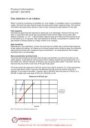
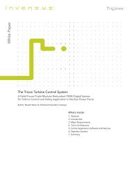
5. Hydrodynamic <strong>Noise</strong> (cont.)5.1.7 A flow chart illustrating the hydrodynamic noise prediction method is shown below.Hydrodynamic <strong>Noise</strong> Prediction Flow ChartOZ3000 01/0217
5. Hydrodynamic <strong>Noise</strong> (cont.)Nomenclaturec F = speed of sound in the fluidc p = speed of sound of the longitudinal waves inthe pipe wallC v = flow coefficientd i = inside diameter of the downstream piped o = outside diameter of the downstream pipef = frequencyf m = octave center frequencyf r = ring frequencyF B = Factor to account for cavitation of multicomponentfluids having a range of vaporpressures.F L = liquid pressure recovery factorl o = reference length of pipe = 1l p = length of pipeL pAe = A-weighted sound-pressure level externalof pipeL WAn = A-weighted sound power level of the n thoctave bandL We = external sound power level (unweighted)L WAe = A-weighted sound power level externalof pipeL Wi = internal sound power level∆L F = valve specific correction value•m = mass flow rateP o = reference sound pressure = 2 x 10 -5p v = absolute vapor pressure of fluid at inlettemperaturep 1 = valve inlet absolute pressurep 2 = valve outlet absolute pressure∆P = differential pressure between upstreamand downstream (p 1 -p 2 )T 1 = inlet absolute temperatureT L = transmission loss (unweighted)t = thickness of wall pipeU 2 = fluid velocity at outlet of valveW m = fluid power loss in the valveW o = reference sound power = 10 -12x = ratio of differential pressure to inletabsolute pressure (∆P/p 1 )x F = differential pressure ratio (∆P/p 1 -p v )x Fz = characteristic pressure ratio for cavitationη F = acoustical efficiency factor for liquid(at φ = 0.75)ρ F = density (specific mass) at p 1 and T 1ρ p = density (specific mass) of pipe material5.2 Application Guidelines and EquipmentSelection5.2.1 Cavitating FluidCavitating fluid, usually water, can be one of themost devastating forces found in control valveapplications. Caused by high localized stressesincurred by vapor implosion, it can quickly destroycritical valve parts if not properly controlled oreliminated. Fortunately, because the imposedstresses are highly localized, the vapor implosionmust occur at or very close to valve metal surfacesto cause damage. This attribute providesmany methods of controlling these destructiveforces, some of which are described below.The damage potential of any cavitating fluid isdirectly proportional to:1. Inlet Pressure P 1 : The inlet pressure isdirectly related to the amount of energy availableto cause damage. The greater the inletpressure, the greater the potential energyapplied to the cavitating fluid and the greaterthe damage potential.2. Degree of Cavitation: This factor, related tothe percentage of the fluid which cavitates,is proportional to the required vs. actualvalve F L and to the degree that the fluidvapor pressure is well-defined. For example,using a valve with a F L of 0.9, a system witha required F L of 0.98 will have a muchgreater percentage of fluid cavitating than asystem with a required F L of 0.92, both at thesame P 1 , and will, therefore, experiencegreater damage. Secondly, a fluid that doesnot have a well-defined vapor pressure, thatwill boil over a wide temperature range, willlikely be self-buffering in a cavitating application.Consult <strong>Masoneilan</strong> Engineering.18 OZ3000 01/02
5. Hydrodynamic <strong>Noise</strong> (cont.)3. Fluid Surface Tension: Since fluid surfacetension affects the amount of pressure recoveryexperienced before vapor implosion, itdirectly affects the amount of energy soreleased. Consequently, fluids with low surfacetension will tend to cause less damage.5.2.2 Equipment ApplicationPreventative Measures: There are several preventativemeasures that can eliminate cavitationdamage. First, however, it cannot be overstressedthat cavitation must be eliminated orcontrolled. Further use of hard materials is not asolution and will only delay ultimate valve failure.On all but the lowest pressure systems, this delaywill be insignificant. Several steps which can betaken are as follows:1. Use a valve with low pressure recovery (highF L ): Often on a moderately cavitating system,cavitation can be eliminated by using alow pressure recovery valve such as a cageguided globe. The goal is to increase thecritical pressure drop, F L2(P 1 -P v ), above thevalve ∆P.2. Reduce ∆P: If the ∆P can be reduced sothat the vena contracta pressure does notdrop below the vapor pressure, cavitation willbe eliminated. Often this can be done bychanging the physical location of the valve(elevation, etc.).3. Use of back pressure plates: If system rangeabilitypermits, use of back pressure plates toincrease P 2 , reducing ∆P below the critical∆P 1 can be the most cost effective solution.Cavitation <strong>Control</strong>: At low to moderately highpressures, cavitation can be controlled by use ofspecially designed trims. These trims function intwo ways:1. High F L : Recall, cavitation damage is directlyproportional to the percentage of fluidcavitating. Consequently, valves with lowpressure recovery (high F L ) will experienceless cavitation damage.2. Containment: Because cavitation is a highlylocalized phenomenon which requires directimpingement on metal surfaces to causedamage, use of a design which diverts thebubble implosion away from metal surfacescan be effective.Most cage guided single and two-stage anticavitationvalves including <strong>Masoneilan</strong>'s LO-DB41000, 21000 and 2600 Series are examples ofcavitation control. Although they can be cost effectivesolutions, there are limitations to theamount of energy that can be absorbed in thismanner. Consult <strong>Masoneilan</strong> Engineering.Cavitation Prevention: Where high potential energyexists (high P 1 ) on cavitating fluid, cavitationmust be eliminated through use of good multiplestagetrim, designed specifically for anti-cavitationservice. Ideally, the pressure staging shouldbe such that the smallest pressure drop occurs atthe last stage to minimize overall valve pressurerecovery. To minimize plug damage, the flowshould be axial, parallel to the plug; for goodcontrol, there should be no dead spots in the trim,providing a good smooth flow characteristic.Finally, since most valves of this type will beseated much of the time, extra-tight shutoff shouldbe provided. See <strong>Masoneilan</strong>'s VRT ® productcatalogs, 78000, 78200 LINCOLNLOG , and77000 product catalogs.Flashing Fluid: When flashing exists in a controlvalve, potential physical damage to the valve mustbe considered. Flashing fluid vapor carries liquiddroplets at high velocity, quickly eroding carbonsteel. Use of higher alloys such as chrome-molywill result in acceptable performance.Variable Resistance Trim Type SSectioned to Show Flow PassagesVariable Resistance Trim Type CSectioned to Show Flow PassagesOZ3000 01/0219
6. References6.1 CEI/IEC 60534-8-3, 2 nd Edition, 2000“<strong>Control</strong> Valve Aerodynamic <strong>Noise</strong> Prediction Method”6.2 CEI/IEC 534-8-4, 1 st Edition, 1994“Prediction of <strong>Noise</strong> Generated by Hydrodynamic Flow”6.3 CEI/IEC 534-8-1, 1 st Edition, 1986“Laboratory Measurement of <strong>Noise</strong> Generated by Aerodynamic Flow Through <strong>Control</strong> Valves”6.4 CEI/IEC 534-8-2, 1 st Edition, 1991“Laboratory Measurement of <strong>Noise</strong> Generated by Hydrodynamic Flow Through <strong>Control</strong> Valves”6.5 ISA Standard ISA S75.17, 1989“<strong>Control</strong> Valve Aerodynamic <strong>Noise</strong> Prediction”6.6 ISA Standard ISA S75.07, 1987“Laboratory Measurement of Aerodynamic <strong>Noise</strong> Generated by <strong>Control</strong> Valves”6.7 ISA Recommended Practice ISA RP75.23, 1995“Consideration for Evaluating <strong>Control</strong> Valve Cavitation”20 OZ3000 01/02
Appendix:Installation ConsiderationsIn closed systems, control valve noise generated by thethrottling process is radiated to the atmosphere throughdownstream piping. <strong>Noise</strong> calculations are based onlaboratory conditions, including an acoustic “free field” (anenvironment without acoustic reflections) and with pipingsystems designed so that they will not contribute togenerated noise. Consequently, like any other equipmentin a facility, these factors should be considered whendeveloping expected installed control valve noise levels.Acoustical EnvironmentThe acoustical environment refers to the type of “field” inwhich the valve is installed. It is a measure of the soundbuild-up expected due to acoustic reflections from boundaries,other equipment, as well as the total size (volume)of the installed environment. These factors are explainedin any basic acoustics text but cannot be anticipated by thecontrol valve manufacturer.Piping Design GuidelinesThe following guidelines should be considered for optimumresults.1. Straight run before and after valveStraight pipe for at least 10 diametersupstream and 20 diameters downstream ofthe valve is recommended.3. Fluid VelocityDepending on velocity, fluid flow may createnoise levels higher than that produced by thecontrol valve. <strong>Masoneilan</strong> provides a meansfor calculating the Mach number (M) at servicepressure and temperature conditions.Average Velocity of Flowing MediumM =Sound Velocity in the Flowing MediumWith LO-DB trim and fluid velocities above 1 / 3Mach, fluid velocity noise must be calculatedand total system sound level reevaluated.4. Expanders and ReducersLike any other source of turbulence in a fluidstream, expanders and reducers may be thecause of additional system noise. Concentricexpanders and reducers with includedangles smaller than 30˚ upstream and 15˚downstream of the valve are recommended.As an exception to the above, short reducers(large included angles) are recommendedwith LO-DB restrictors because of their inherentstiffness and the fact that velocity is lowupstream of the restrictors.RestrictorsFlowFlowD 1 D 210 D 1 20 D 1Shortest PossibleIntermediateExpanders2. Isolating ValvesIsolating block valves must be selected toensure minimum resistance to fluid flow. Fullbore type is preferred.5. Bends, T's and other Piping ConnectionsDrastic disruptions in the fluid stream, especiallyif high fluid velocity exists, are potentialnoise sources. Possible improvements toconventional design for piping connectionsare shown in Figure 6.Piping SupportsA vibration free piping system is not always possible toobtain, especially when thin wall piping such as Schedules5S and 10S are used. Supports in strategic locations, however,will alleviate a lot of the potential structural problems.At the same time, they reduce the possibility of structureborne noise. In some cases, piping may be buried toreduce noise and vibration problems.OZ3000 01/0221
Appendix:Installation Considerations (cont.)Preferred DesignBendAngularOne-Plane TurnA. Pipe TurnsB. InletsUsual DesignElbowLateralDouble OffsetExtreme Sound LevelsFluid borne valve generated noise induces mechanicalvibration in the piping system which is radiated to the environmentas valve noise. The valve sound level is indicativeof this surface motion. Excessive vibration can cause failureor damage to valve and pipe mounted instruments, andaccessories. Piping cracks, loose flange bolts, and otherproblems can develop. For this reason, valve noise shouldbe limited to 115-120 dBA. If higher levels are expected,LO-DB valves, LO-DB static restrictors or other alternativesshould be used to reduce noise below the recommendedlevels. Note that pipe insulation and certain other “add on”noise control treatments, which do not change the pipe wallsurface motion, are ineffective. In most cases, suchextreme sound levels are precluded by occupational andenvironmental noise requirements anyway.C. Elevation ChangesStreamlinedOpposingD. JunctionsStreamlined BranchingConventional BranchE. ConnectionsFigure 6Reference Articles:1. “Escape Piping Vibrations While Designing,” J. C. Wachel and C. L. Bates, Hydrocarbon Processing, October 1976.2. “How to Get the Best Process Plant Layouts for Pumps and Compressors,” R. Kern, Chemical Engineering, December 1977.3. “Predicting <strong>Control</strong> Valve <strong>Noise</strong> from Pipe Vibrations,” C. L. Reed, Instrumentation Technology, February 1976.4. "Improving Prediction of <strong>Control</strong> Valve <strong>Noise</strong>," H. Boger, InTech, August 1998.5. “Avoid <strong>Control</strong> Valve Application Problems with Physics-Based Models," J. A. Stares and K. W. Roth, Hydrocarbon Processing,August 2001.22 OZ3000 01/02
OZ3000 01/0223
<strong>Masoneilan</strong> Direct Sales OfficesAUSTRIADresser Valves Europe GmbHKaiserallee 14A-2100 Korneuburg (near Wien), AustriaPhone: 43-2262-63689Fax: 43-2263-6368915BELGIUMDresser Europe S.p.r.L.281-283 Chaussee de Bruxelles281-283 Brusselsesteenweg1190 Brussels, BelgiumPhone: 32-2-344-0970Fax: 32-2-344-1123BRAZILDresser Industria E Comercio LtdaDivisao <strong>Masoneilan</strong>Rua Senador Vergueiro, 43309521-320 Sao Caetano Do SulSao Paolo, BrazilPhone: 55-11-453-5511Fax: 55-11-453-5565CANADAAlbertaDresser Flow <strong>Control</strong>DI Canada, Inc.Suite 1300, 311-6th Ave., S.W.Calgary, Alberta T2P 3H2CanadaPhone: 403-290-0001Fax: 403-290-1526OntarioDresser Flow <strong>Control</strong>DI Canada, Inc.5010 North Service RoadBurlington, Ontario L7L 5R5CanadaPhone: 905-335-3529Fax: 905-336-7628CHINADresserSuite 2403, Capital Mansion6 Xinyuannan RoadChao Yang districtBeijing 100040Phone: 86-10-6466-1164Fax: 86-10-6466-0195FRANCEDresser Produits Industriels S.A.S.Division <strong>Masoneilan</strong>4, place de Saverne92400 CourbevoieFrancePhone: 33-1-49-04-90-00Fax: 33-1-49-04-90-10GERMANYDresser Valves Europe GmbHKlein-Kollenburg-Strasse 78-8047877 Willich, GermanyMailing Address:P.O. Box 120847860 Willich, GermanyPhone: 49-2156-9189-0Fax: 49-2156-9189-99INDIADresser Valve India Pvt. Ltd.305/306 “Midas” - Sahar PlazaMathurdas Vasanji RoadJ.B. Nagar - Andheri EastMumbai, India 400 059Phone: 91-22-835-4790Fax: 91-22-835-4791ITALYDresser Italia S.r.L.<strong>Masoneilan</strong> OperationVia Cassano, 7780020 Casavatore (Naples), ItalyPhone: 39-81-7892-111Fax: 39-81-7892-208JAPANNiigata <strong>Masoneilan</strong> Company, Ltd.20th Floor, Marive East TowerWBG 2-6 Nakase, Mihama-KuChiba-shi, Chiba 261-7120, JapanPhone: 81-43-297-9222Fax: 81-43-299-1115KOREADresser Korea, Inc.#2107 Kuk Dong Building60-1, 3-Ka, Choongmu-roChung-Ku, Soeul, 100705Phone: 82-2-274-0792Fax: 82-2-274-0794KUWAITDresserP.O. Box 242Safat 13003, KuwaitCourier:Flat No. 36, Floor 8Gaswa Complex, MahboulaKuwaitPhone: 965-9061157MALAYSIADresser Flow <strong>Control</strong> - Far EastBusiness Suite 19A-9-1Level 9, UOA CentreNo. 19 Jalan Pinang50450 Luala Lumpur, MalaysiaPhone: 60-3-2163-2322Fax: 60-3-2163-6312MEXICODresser Valve de Mexico, S.A. de C.V.Henry Ford No. 114, Esq. FultonFraccionamiento Industrial San Nicolas54030 Tlalnepantla Estado de MexicoPhone: 52-5-310-9863Fax: 52-5-310-5584THE NETHERLANDSDresser Valves EuropeSteenhouwerstraat 113194 AG HoogvlietThe NetherlandsMailing Address:P.O. Box 640NL3190 AN Hoogvliet RTThe NetherlandsPhone: 31-10-438-4122Fax: 31-10-438-4443SINGAPOREDresser Singapore, Pte. Ltd.16, Tuas Avenue 8Singapore 639231Phone: 65-861-6100Fax: 65-861-7172SOUTH AFRICADresser Ltd., South Africa BranchP.O. Box 2234, 16 Edendale RoadEastleigh, Edenvale 1610Republic of South AfricaPhone: 27-11-452-1550Fax: 27-11-452-6542SPAIN<strong>Masoneilan</strong> S.A.C/ Murcia 39 C08830 Sant Boi de LlobregatBarcelona, SpainPhone: 34-93-652-6430Fax: 34-93-652-6444SWITZERLANDDresser Valves Europe SAFrauntalweg 76CH-8045 Zurich, SwitzerlandMailing Address:P.O. Box 3568CH-8021 Zurich, SwitzerlandPhone: 41-1-450 28 91Fax: 41-1-450 28 95UNITED ARAB EMIRATESDresserMiddle East OperationsPost Box 61302R/A 8, Units JA01/JA02Jebel Ali Free ZoneUnited Arab EmiratesCourier:Units Nos. JAO1 + JAO2Roundabout 8Jebel Ali Free ZoneUnited Arab EmiratesPhone: 971-4-8838-752Fax: 971-4-8838-038UNITED KINGDOMDI U.K. LimitedTrevithick WorksGillibrands Estate, SkelmersdaleLancashire WN8 9TU, EnglandUnited KingdomPhone: 44-1695-52600Fax: 44-1695-52662DI U.K.Unit 4, Suite 1.1, Nobel HouseGrand Union Office ParkPacket Boat Lane, UxbridgeMiddlesex UB8 2GH, EnglandUnited KingdomPhone: 44-1895-454900Fax: 44-1895-454919UNITED STATESNorthern RegionDresser Flow <strong>Control</strong>85 Bodwell StreetAvon, MA 02322-1190Phone: 508-586-4600Fax: 508-427-8971Southern RegionDresser Flow <strong>Control</strong>11100 West Airport Blvd.Stafford, TX 77477-3014Phone: 281-568-2211Toll Free: 800-847-1099Fax: 281-568-1414South Texas OperationsDresser Flow <strong>Control</strong>4841 Leopard StreetCorpus Christi, TX 78408-2621Phone: 361-877-2414Fax: 361-584-1196<strong>Masoneilan</strong> AftermarketSales & Service Center16030 Bear Bayou DriveChannelview, TX 77530Phone: 281-862-1500Fax: 281-862-1550Experience, Knowledge & Technology...In <strong>Control</strong>Visit us at www.masoneilan.comCopyright 2001. Dresser Flow <strong>Control</strong>