basic system diagrams door phone systems function ... - Dialog-Urmet
basic system diagrams door phone systems function ... - Dialog-Urmet
basic system diagrams door phone systems function ... - Dialog-Urmet
- No tags were found...

You also want an ePaper? Increase the reach of your titles
YUMPU automatically turns print PDFs into web optimized ePapers that Google loves.
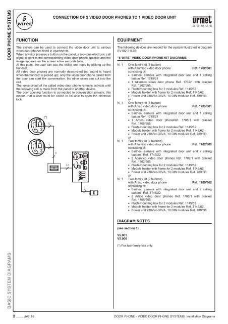
DOOR PHONE SYSTEMSFUNCTIONThe <strong>system</strong> can be used to connect the video <strong>door</strong> unit to variousvideo <strong>door</strong> <strong>phone</strong>s fi tted in apartments.When a visitor presses a button on the panel, a two-tone electronic callsignal is sent to the corresponding video <strong>door</strong> <strong>phone</strong> speaker and theimage appears on the screen a few seconds later.At this point, the user can see the visitor and reply by picking up thehandset.All video <strong>door</strong> <strong>phone</strong>s are normally deactivated (no sound is heardwhen the handset is picked up); only the video <strong>door</strong> <strong>phone</strong> called fromthe <strong>door</strong> can start the conversation. No other users can cut into thecall.The voice circuit of the called video <strong>door</strong> <strong>phone</strong> remains activate untilthe following call is made from the panel to another device.The <strong>door</strong> opening <strong>function</strong> is connected to conversation privacy; thismeans that a user must be called to be able to open the electricallock.(*)57CONNECTION OF 2 VIDEO DOOR PHONES TO 1 VIDEO DOOR UNIT610TC2EQUIPMENTThe following devices are needed for the <strong>system</strong> illustrated in diagramSV102-3147B:“5-WIRE” VIDEO DOOR PHONE KIT DIAGRAMSN. 1 One-family kit (1 button)with Atlantico video <strong>door</strong> <strong>phone</strong> Ref. 1702/601consisting of:• Sinthesi camera with integrated <strong>door</strong> unit and 1 callingbutton Ref. 1745/21• 1 Atlantico video <strong>door</strong> <strong>phone</strong> Ref. 1702/1 with bracketRef. 1202/955• Flush-mounting box for 2 modules Ref. 1145/52• Module holder with frame for 2 modules Ref. 1145/62• Power unit 230Vac-38VA, 10 DIN modules Ref. 789/5BorN. 1 One-family kit (1 button)with Artico video <strong>door</strong> <strong>phone</strong> Ref. 1705/601consisting of:• Sinthesi camera with integrated <strong>door</strong> unit and 1 callingbutton Ref. 1745/21• 1 Artico video <strong>door</strong> <strong>phone</strong>Ref. 1705/1 with bracketRef. 1705/955• Flush-mounting box for 2 modules Ref. 1145/52• Module holder with frame for 2 modules Ref. 1145/62• Power unit 230Vac-38VA, 10 DIN modules Ref. 789/5BorN. 1 Two-family kit (2 buttons)with Atlantico video <strong>door</strong> <strong>phone</strong> Ref. 1702/602consisting of:• Sinthesi camera with integrated <strong>door</strong> unit and 2 callingbuttons Ref. 1745/22• 2 Atlantico video <strong>door</strong> <strong>phone</strong>s Ref. 1702/1 with bracketRef. 1202/955• Flush-mounting box for 2 modules Ref. 1145/52• Module holder with frame for 2 modules Ref. 1145/62• Power unit 230Vac-38VA, 10 DIN modules Ref. 789/5BorN. 1 Two-family kit (2 buttons)with Artico video <strong>door</strong> <strong>phone</strong> Ref. 1705/602consisting of:• Sinthesi camera with integrated <strong>door</strong> unit and 2 callingbuttons Ref. 1745/22• 2 Artico video <strong>door</strong> <strong>phone</strong>s Ref. 1705/1 with bracketRef. 1705/955• Flush-mounting box for 2 modules Ref. 1145/52• Module holder with frame for 2 modules Ref. 1145/62• Power unit 230Vac-38VA, 10 DIN modules Ref. 789/5BDIAGRAM NOTES(see section 1)V5.001V5.006(*) For two-family kits onlyBASIC SYSTEM DIAGRAMS2 −−−− sec.1e DOOR PHONE - VIDEO DOOR PHONE SYSTEMS: Installation Diagrams
CONNECTION OF 2 VIDEO DOOR PHONES TO 1 VIDEO DOOR UNIT(*)R1R2BACA(V5.006)SV102-3147BDOOR PHONE SYSTEMSR1R2ABCATCC1C2VIDEOPOWER SUPPLY+R-6+6CAMERA UNITWITH DOOR UNITAND 2 BUTTONSG/T3PS45FSN1/~1/~~SEBASIC SYSTEM DIAGRAMSR1 AB+TCLock ReleaseAPR1R2PS1/~~0~12SE2R1+TCSE1R20230MAIN~ELECTRIC LOCKDOOR PHONE - VIDEO DOOR PHONE SYSTEMS: Installation Diagramssec.1e−−−− 3
DOOR PHONE SYSTEMSFUNCTIONCONNECTION OF 1 VIDEO DOOR PHONE TO 1 VIDEO DOOR UNITThe <strong>system</strong> can be used to connect the video <strong>door</strong> unit to the video<strong>door</strong> <strong>phone</strong> fi tted in the apartment.When a visitor presses a button on the panel, a two-tone electronic callsignal is sent to the corresponding video <strong>door</strong> <strong>phone</strong> speaker and theimage appears on the screen a few seconds later.At this point, the user can see the visitor and reply by picking up thehandset.The <strong>door</strong> opening <strong>function</strong> is connected to conversation privacy; thismeans that a user must be called to be able to open the electricallock.EQUIPMENTThe following devices are needed for the <strong>system</strong> illustrated in diagramSV102-2082C:VIDEO DOOR PHONE REFERENCESN. 1 One-family kit(1 button) Ref. 956/31consisting of:• Smyle panel with camera and 1 button with built-in <strong>door</strong>unit.• 1 Artico video <strong>door</strong> <strong>phone</strong> with bracket• Power unit 110-230Vac 38VA, 7 DIN modules6DIAGRAM NOTES(see section 1)TCV5.007V5.01142(V5.011)SV102-2082CR3POWER SUPPLYMAIN~BASIC SYSTEM DIAGRAMSTCLockReleaseELECTRIC LOCK4 −−−− sec.1e DOOR PHONE - VIDEO DOOR PHONE SYSTEMS: Installation Diagrams
FUNCTIONCONNECTION OF 2 VIDEO DOOR PHONES TO 1 VIDEO DOOR UNITThe <strong>system</strong> can be used to connect the video <strong>door</strong> unit to the video<strong>door</strong> <strong>phone</strong> fi tted in the apartment.When a visitor presses a button on the panel, a two-tone electronic callsignal is sent to the corresponding video <strong>door</strong> <strong>phone</strong> speaker and theimage appears on the screen a few seconds later.At this point, the user can see the visitor and reply by picking up thehandset.The <strong>door</strong> opening <strong>function</strong> is connected to conversation privacy; thismeans that a user must be called to be able to open the electricallock.6EQUIPMENTThe following devices are needed for the <strong>system</strong> illustrated in diagramSV102-2081B:VIDEO DOOR PHONE KIT DIAGRAMSN. 1 Two-family kit(2 buttons) Ref. 956/32consisting of:• Smyle panel with camera and 2 buttons with built-in <strong>door</strong>unit.• 2 Artico video <strong>door</strong> <strong>phone</strong>s with bracket• Power unit 110-230Vac 38VA, 7 DIN modulesDOOR PHONE SYSTEMS87DIAGRAM NOTES(see section 1)V5.007V5.011TC42(V5.011)R3SV102-2081B2(V5.006)(V5.011)R31POWER SUPPLYMAIN~TCLockReleaseELECTRIC LOCKBASIC SYSTEM DIAGRAMSDOOR PHONE - VIDEO DOOR PHONE SYSTEMS: Installation Diagramssec.1e−−−− 5
DOOR PHONE SYSTEMSFUNCTIONThe 5-wire video <strong>door</strong> <strong>phone</strong> <strong>system</strong> implements conversation privacy,call and <strong>door</strong> opener <strong>function</strong>s in normal <strong>door</strong> <strong>phone</strong> <strong>system</strong>s with only5 wires in the riser column: 4 commons + 1 single for each device.The <strong>door</strong> unit is powered with only two wires and a transformer at12V~.The most interesting application of a 5-wire <strong>system</strong> is in old buildingswhere a <strong>door</strong> <strong>phone</strong> <strong>system</strong> is already fi tted. The existing <strong>system</strong> canbe transformed into a video <strong>door</strong> <strong>phone</strong> <strong>system</strong> without adding wiresto the column or in the apartments.Specifi c conversation privacy circuits must be fi tted in the panel forensuring conversation privacy for all video <strong>door</strong> <strong>phone</strong>s in the <strong>system</strong>(one for each button). All video <strong>door</strong> <strong>phone</strong>s are normally deactivated(no sound is heard when the handset is picked up); only the video <strong>door</strong><strong>phone</strong> called from the <strong>door</strong> can start the conversation. No other userscan cut into the call.The voice circuit of the called video <strong>door</strong> <strong>phone</strong> remains activate untilthe following call is made from the panel to another device.The <strong>door</strong> opening <strong>function</strong> is connected to conversation privacy; thismeans that a user must be called to be able to open the electricallock.55552 x 82Ω 1/4WVIDEODISTRIBUTORVIDEODISTRIBUTORCONNECTION OF SEVERAL VIDEO DOOR PHONETO 1 VIDEO OUTDOOR STATION4+n4+n5555EQUIPMENTThe following devices are needed for the <strong>system</strong> illustrated in diagramSV102-2633H:VIDEO DOOR PHONE REFERENCESAtlantico modelN. X Video <strong>door</strong> <strong>phone</strong> Ref. 1702/1N. X Bracket Ref. 1202/955orArtico modelN. X Video <strong>door</strong> <strong>phone</strong> Ref. 1705/1N. X Bracket Ref. 1705/955VIDEO OUTDOOR STATION REFERENCESSinthesi modelN. 1 Module with camera and <strong>door</strong> unit Ref. 1745/20-/21-/22N. X Button modules Ref. 1145/11-/12-/13-/14N. X/4 Conversation privacy device Ref. 1145/74orThe panels must be installed in fl ush-mounting boxes withmodule holder frames or in cases with hood for wall-mountedversions. Refer to “Sinthesi panel” section of Door<strong>phone</strong> andVideo<strong>door</strong><strong>phone</strong> <strong>system</strong> - product technical manual.K-Steel modelN. 1 Module camera Ref. 1755/30AN. 1 Module with <strong>door</strong> unit Ref. 1155/30-/31-/32AN. X Button modules Ref. 1155/11-/12A-/13A-/14AN. X/4 Conversation privacy device Ref. 1145/74The panels must be installed in fl ush-mounting boxes withmodule holder frames or in cases with hood for wall-mountedversions. Refer to “K-Steel modular vandal-proof panel” sectionof Door<strong>phone</strong> and Video<strong>door</strong><strong>phone</strong> <strong>system</strong> - product technicalmanual.TCTC2 10+nor725 modelN. 1 Panel with N buttons Mod. 725N. 1 Amplifi ed <strong>door</strong> unit Ref. 1035/67N. 1 Camera Ref. 725/600N. 1 Video adapter Ref. 1742/13AN. 1 Front plate Ref. 725/601-/602N. X/4 Conversation privacy device Ref. 1035/25The panels must be installed in fl ush-mounting boxes withmodule holder frames or in cases with hood for wall-mountedversions. Refer to “Panels with anodized aluminium front plateMod. 725” section of Door<strong>phone</strong> and Video<strong>door</strong><strong>phone</strong> <strong>system</strong>- product technical manual.BASIC SYSTEM DIAGRAMSPOWER SUPPLY REFERENCESN. 1 Video power supply Ref. 789/5BN. 1 Video distributor Ref. 955/40DIAGRAM NOTES(see section 1)C4.007 C4.008 C4.018 CU.009 VD.002V5.001 VU.002 VX.006 VX.008 VX.0146 −−−− sec.1e DOOR PHONE - VIDEO DOOR PHONE SYSTEMS: Installation Diagrams
CONNECTION OF SEVERAL VIDEO DOOR PHONETO 1 VIDEO OUTDOOR STATIONR1R2ABCAR1R2ABA BIIIR2R1OutputII2 x 82 1/4WR1R2ABR1R2ABCASV102-2633HDOOR PHONE SYSTEMSVIDEODISTRIBUTORR1R2ABCAR1R2ABIV IInputR1R2ABR1R2ABCAA BR2R1TO THE FOLLOWINGVIDEO DISTRIBUTORA BR2R1R1R2ABCAR1R2ABOutputIII IIR1R2ABR1R2ABCAVIDEODISTRIBUTORR1R2ABCATo thefollowingTo the following conversationmoduleprivacy device(C4.007)(C4.008)BUTTON MODULER1R2ABIVA BInputIR2R1R1R2ABR1R2ABCAName taglightingTC(CU.009)P. E.PS43SN1/~ 5 ~2Camera+AdapterMod.7254 1 1 4ABR1+TC(VU.002)ELECTRIC LOCK(VX.006)To thefollowingconversationprivacydeviceName taglighting(C4.018)(VD.002)G/T 4 1~12 U4C4~0 U3C3~0 U2C2~12 U1C1G/T4 1 (VX.006)C2C1C2C1~12~0PS PSG/T 3G/TF F5 54 4SN SN1 1/~1/~ 1/~~ ~2 SER1 BA R1 BA+TC +TC~12~0K-Steel SinthesiELECTRIC LOCKMod. K-Steel/SinthesiLockReleaseName taglightingLINE~LINE~(VX.014)-6+6APR1R2+RPS1/~~0~12SE2SE1R2R1+TC~~~0~12~~VIDEOPOWER SUPPLY(VX.008)LIGHT BULBTRANSFORMERBASIC SYSTEM DIAGRAMSDOOR PHONE - VIDEO DOOR PHONE SYSTEMS: Installation Diagramssec.1e−−−− 7
DOOR PHONE SYSTEMSFUNCTIONCONNECTION OF SEVERAL VIDEO DOOR PHONE TO 2 VIDEO OUTDOOR STATIONAutomatic switching during calls (Mod. Sinthesi or Mod. K-Steel)This <strong>system</strong> allows the connection of a column of video <strong>door</strong> <strong>phone</strong>sto 2 video out<strong>door</strong> stations with automatic switching.When a visitor presses a call button on one of the two push buttonpanels, in the called apartment the bitonal electronic call is sent to thecorresponding video <strong>door</strong> <strong>phone</strong> loudspeaker and the image appearson the screen after about 8 seconds.During this phase, the relay box automatically inserts the relativeloudspeaking unit and TV camera, excluding the other video out<strong>door</strong>station from the service.At this point, the user sees the visitor and may respond, if desired,lifting the handset. At the end of the call, only the electric lock of theentrance concerned is activated pressing the key .If, during a conversation, a call is made from the other push buttonpanel towards another video <strong>door</strong> <strong>phone</strong>, the fi rst will automaticallyswitch off and the last video <strong>door</strong> <strong>phone</strong> called will be activated. Itis not possible therefore to communicate with the 2 video out<strong>door</strong>stations at the same time in that they operate alternatively and aremutually exclusive.EQUIPMENTThe following devices are needed for the <strong>system</strong> illustrated in diagramSV102-2902G:VIDEO DOOR PHONE REFERENCESAtlantico modelN. X Video <strong>door</strong> <strong>phone</strong> Ref. 1702/1N. X Bracket Ref. 1202/955orArtico modelN. X Video <strong>door</strong> <strong>phone</strong> Ref. 1705/1N. X Bracket Ref. 1705/955VIDEO OUTDOOR STATION REFERENCESTC552 x 82Ω 1/4WVIDEODISTRIBUTOR55Sinthesi modelN. 2 Module with camera and <strong>door</strong> unit Ref. 1745/20-/21-/22N. X Button modules Ref. 1145/11-/12-/13-/14N. X/4 Conversation privacy device Ref. 1145/74orThe panels must be installed in fl ush-mounting boxes withmodule holder frames or in cases with hood for wall-mountedversions. Refer to “Sinthesi panel” section of Door<strong>phone</strong> andVideo<strong>door</strong><strong>phone</strong> <strong>system</strong> - product technical manual.54+n5K-Steel modelN. 2 Module camera Ref. 1755/30AN. 2 Module with <strong>door</strong> unit Ref. 1155/30-/31-/32AN. X Button modules Ref. 1155/11-/12A-/13A-/14AN. X/4 Conversation privacy device Ref. 1145/745VIDEODISTRIBUTOR4+n5The panels must be installed in fl ush-mounting boxes withmodule holder frames or in cases with hood for wall-mountedversions. Refer to “K-Steel modular vandal-proof panel” sectionof Door<strong>phone</strong> and Video<strong>door</strong><strong>phone</strong> <strong>system</strong> - product technicalmanual.POWER SUPPLY REFERENCESN. 1 Video power supply Ref. 789/5BN. 1 Transformer Ref. 9000/230N. 1 Relay box Ref. 788/51N. X Video distributor Ref. 955/40TCTC2 13+n 14+n2DIAGRAM NOTES(see section 1)C4.007 C4.008 C4.016 C4.018 CU.009 V5.001VD.002 VX.006 VX.008 VX.014BASIC SYSTEM DIAGRAMSVX.021Cut or remove the jumpers on the device(s):a) PS - G/Tb) 4 - F8 −−−− sec.1e DOOR PHONE - VIDEO DOOR PHONE SYSTEMS: Installation Diagrams
DOOR PHONE SYSTEMSFUNCTIONCONNECTION OF SEVERAL VIDEO DOOR PHONE TO 2 VIDEO OUTDOOR STATIONAutomatic switching during calls (Mod. 725)This <strong>system</strong> allows the connection of a column of video <strong>door</strong> <strong>phone</strong>sto 2 video out<strong>door</strong> stations with automatic switching.When a visitor presses a call button on one of the two push buttonpanels, in the called apartment the bitonal electronic call is sent to thecorresponding video <strong>door</strong> <strong>phone</strong> loudspeaker and the image appearson the screen after about 8 seconds.During this phase, the relay box automatically inserts the relativeloudspeaking unit and TV camera, excluding the other video out<strong>door</strong>station from the service.At this point, the user sees the visitor and may respond, if desired,lifting the handset. At the end of the call, only the electric lock of theentrance concerned is activated pressing the key .If, during a conversation, a call is made from the other push buttonpanel towards another video <strong>door</strong> <strong>phone</strong>, the fi rst will automaticallyswitch off and the last video <strong>door</strong> <strong>phone</strong> called will be activated. Itis not possible therefore to communicate with the 2 video out<strong>door</strong>stations at the same time in that they operate alternatively and aremutually exclusive.EQUIPMENTThe following devices are needed for the <strong>system</strong> illustrated in diagramSV102-2913B:VIDEO DOOR PHONE REFERENCESAtlantico modelN. X Video <strong>door</strong> <strong>phone</strong> Ref. 1702/1N. X Bracket Ref. 1202/955orArtico modelN. X Video <strong>door</strong> <strong>phone</strong> Ref. 1705/1N. X Bracket Ref. 1705/955VIDEO OUTDOOR STATION REFERENCESTC552 x 82Ω 1/4WVIDEODISTRIBUTOR4+n55725 modelN. 2 Panel with N buttons Mod. 725N. 2 Amplifi ed <strong>door</strong> unit Ref. 1035/67N. 2 Camera Ref. 725/600N. 2 Video adapter Ref. 1742/13AN. 2 Front plate Ref. 725/601-/602N. X/4 Conversation privacy device Ref. 1035/25The panels must be installed in fl ush-mounting boxes withmodule holder frames or in cases with hood for wall-mountedversions. Refer to “Panels with anodized aluminium front plateMod. 725” section of Door<strong>phone</strong> and Video<strong>door</strong><strong>phone</strong> <strong>system</strong>- product technical manual.55VIDEODISTRIBUTOR4+n55POWER SUPPLY REFERENCESN. 1 Video power supply Ref. 789/5BN. 1 Transformer Ref. 9000/230N. 1 Relay box Ref. 788/51N. X Video distributor Ref. 955/40DIAGRAM NOTES(see section 1)CU.009 V5.001 VU.002 VX.006 VX.008 VX.014TCTC2 13+n 14+nBASIC SYSTEM DIAGRAMS210 −−−− sec.1e DOOR PHONE - VIDEO DOOR PHONE SYSTEMS: Installation Diagrams
CONNECTION OF SEVERAL VIDEO DOOR PHONE TO 2 VIDEO OUTDOOR STATIONAutomatic switching during calls (Mod. 725 or Mod. Domus Aura)COLUMNOutputSV102-2913BDOOR PHONE SYSTEMSVIDEODISTRIBUTORInputTO THE FOLLOWINGVIDEO DISTRIBUTOROutputVIDEODISTRIBUTORInputPushbuttonpanelPushbuttonpanel(CU.009)CONVERSATIONPRIVACY DEVICE(VX.006)RELAYBOX(CU.009)"1""2"TCTC(VU.002)TV Camera+adapterELECTRICLOCKTRANSFORMER(VX.008)LockReleaseLINE~VIDEO POWERSUPPLY(VX.008)LINE~LockReleaseName taglighting(VX.014)TV Camera+adapterELECTRICLOCKLINE~LIGHT BULBTRANSFORMER(VU.002)BASIC SYSTEM DIAGRAMSDOOR PHONE - VIDEO DOOR PHONE SYSTEMS: Installation Diagramssec.1e−−−− 11
DOOR PHONE SYSTEMSFUNCTIONCONNECTION OF SEVERAL VIDEO DOOR PHONE TO 4 VIDEO OUTDOORSTATIONSAutomatic switching during calls (Mod. Sinthesi or Mod. K-Steel)This <strong>system</strong> allows the connection of a column of video <strong>door</strong> <strong>phone</strong>sto 4 video out<strong>door</strong> stations with automatic switching. Therefore, it issuitable for a building with 4 entrances common to all apartments.When a visitor presses a call button on one of the two push buttonpanels, in the called apartment the bitonal electronic call is sent to thecorresponding video <strong>door</strong> <strong>phone</strong> loudspeaker and the image appearson the screen after about 7 seconds. During this phase, the relay boxautomatically inserts the relative loudspeaking unit and TV camera,excluding the other video out<strong>door</strong> station from the service. At thispoint, the user sees the visitor and may respond, if desired, lifting thehandset. At the end of the call, only the electric lock of the entranceconcerned is activated pressing the key . If, during a conversation,a call is made from the other push button panel towards another video<strong>door</strong> <strong>phone</strong>, the fi rst will automatically switch off and the last video<strong>door</strong> <strong>phone</strong> called will be activated. In this <strong>system</strong> it is not possibleto speak simultaneously from the four out<strong>door</strong> stations because theywork one at a time in automatic switching.EQUIPMENTThe following devices are needed for the <strong>system</strong> illustrated in diagramSV102-3092D:VIDEO DOOR PHONE REFERENCESAtlantico modelN. X Video <strong>door</strong> <strong>phone</strong> Ref. 1702/1N. X Bracket Ref. 1202/955orArtico modelN. X Video <strong>door</strong> <strong>phone</strong> Ref. 1705/1N. X Bracket Ref. 1705/955VIDEO OUTDOOR STATION REFERENCESTC552 x 82Ω 1/4WVIDEODISTRIBUTOR4+n55Sinthesi modelN. 4 Module with camera and <strong>door</strong> unit Ref. 1745/20-/21-/22N. X Button modules Ref. 1145/11-/12-/13-/14N. X/4 Conversation privacy device Ref. 1145/74orThe panels must be installed in fl ush-mounting boxes withmodule holder frames or in cases with hood for wall-mountedversions. Refer to “Sinthesi panel” section of Door<strong>phone</strong> andVideo<strong>door</strong><strong>phone</strong> <strong>system</strong> - product technical manual.5VIDEODISTRIBUTOR5K-Steel modelN. 4 Module camera Ref. 1755/30AN. 4 Module with <strong>door</strong> unit Ref. 1155/30-/31-/32AN. X Button modules Ref. 1155/11-/12A-/13A-/14AN. X/4 Conversation privacy device Ref. 1145/7454+n5The panels must be installed in fl ush-mounting boxes withmodule holder frames or in cases with hood for wall-mountedversions. Refer to “K-Steel modular vandal-proof panel” sectionof Door<strong>phone</strong> and Video<strong>door</strong><strong>phone</strong> <strong>system</strong> - product technicalmanual.2TC14+n14+nTC2POWER SUPPLY REFERENCESN. 1 Video power supply Ref. 789/5BN. 3 Transformer Ref. 9000/230N. 1 Relay box Ref. 788/54N. X Video distributor Ref. 955/40DIAGRAM NOTESTCTC2 14+n 15+n 2(see section 1)C4.007 C4.008 C4.016 C4.018 CU.009 V5.001VD.002 VX.006 VX.008 VX.014BASIC SYSTEM DIAGRAMSVX.021Cut or remove the jumpers on the device(s):a) PS - G/Tb) 4 - F12 −−−− sec.1e DOOR PHONE - VIDEO DOOR PHONE SYSTEMS: Installation Diagrams
CONNECTION OF SEVERAL VIDEO DOOR PHONE TO 4 VIDEO OUTDOORSTATIONSAutomatic switching during calls (Mod. Sinthesi or Mod. K-Steel)R1R2ABCAR1R2ABR1R2OutputIIABIVCOLUMN2 x 82 1/4WR1R2ABR1R2ABCASV102-3092DDOOR PHONE SYSTEMSDISTRIBUTORR1R2ABCAR2R1ABIIIIInputR1R2ABR1R2ABCAR1R2ABTO THE FOLLOWINGVIDEO DISTRIBUTORR1R2ABR1R2ABCAR1R2ABOutputIIIVR1R2ABR1R2ABCADISTRIBUTORR1R2ABCAR2R1ABIIIIInputR1R2ABR1R2ABCAR1R2ABTo the followingmodule(C4.007)(C4.008)Button module(C4.007)(C4.008)Button moduleTo the followingmoduleName taglighting(C4.018)G/T~12~0~0~12G/TC2C1U4U3U2U1C2C1R1R2 1 2 6 9 V3V5COLUMNU4U3U2U1C2C1G/T~12~0~0~12G/TC2C1Name taglighting(C4.018)"3"TC~12~0G/T G/T34PS PS4FSN SN F5 51 1/~1/~ 1/~~ ~2 SE(VX.021)C3SN3V3+6V5SE~0~12INPUTCINPUTBC2SN2V3+6V5SE~0~12(VX.021)G/T4PSFSN51/~1/~~SE~12~0G/T34PSFSN511/~~2TC"2"(C4.016)(CU.009)(VD.002)AB+TCR1~12~0K-SteelAB+TCR1SinthesiLockReleaseLINE~12+TCR1-612+TCR1-6LINE~LockReleaseAB+TCR1SinthesiAB+TCR1~12~0K-Steel(VD.002)(C4.016)(CU.009)To the followingmoduleELECTRICLOCK~ ~ ~ ~12 0TRANSFORMER(VX.008)~ ~12 0~(VX.008)~TRANSFORMERTo the followingconversationprivacy deviceELECTRICLOCKTo the followingmoduleName taglighting(C4.018)(C4.007)(C4.008)Button moduleG/T~12~0~0~12G/TC2C1U4U3U2U1C2C1RELAYBOXConversationprivacy device(VX.006)14C4C3C2C11 4(C4.007)(C4.008)Button moduleU4U3U2U1C2C1G/T~12~0~0~12G/TC2C1Name taglighting(C4.018)"4"TC(C4.016)(CU.009)(VD.002)~12~0G/T G/T34PS PS4FSN SN F5 51 1/~1/~ 1/~~ ~2 SEAB+TCR1~12~0K-SteelAB+TCR1SinthesiELECTRICLOCK(VX.021)LockReleaseLINE~~ ~ ~ ~12 0TRANSFORMER(VX.008)(VX.008)C4SN4V3+6V5SE~0~1212+TCR1-6VIDEO POWERSUPPLYINPUTDVOLTAGEINPUTA-6I-6U +TC R2 R1 AP +6~12 ~B ~A ~0SEC1SN1V3+6V5SE~0~1212+TCR1-6GNDLINE~LINE~(VX.014)Name taglightingPS+TC ~12R2 ~0R1 ~ ~1/~ ~ ~ ~ ~12(VX.021)LockReleaseLIGHT BULBTRANSFORMERG/T4PSFSN51/~1/~~SEAB+TCR1Sinthesi~12~0G/T34PSFSN511/~~2AB+TCR1~12~0K-SteelELECTRICLOCK(VD.002)TC(C4.016)(CU.009)"1"BASIC SYSTEM DIAGRAMSDOOR PHONE - VIDEO DOOR PHONE SYSTEMS: Installation Diagramssec.1e−−−− 13
DOOR PHONE SYSTEMSFUNCTIONThis <strong>system</strong> allows the connection of a column of video <strong>door</strong> <strong>phone</strong>sto 4 video out<strong>door</strong> stations with automatic switching. Therefore, it issuitable for a building with 4 entrances common to all apartments.When a visitor presses a call button on one of the two push buttonpanels, in the called apartment the bitonal electronic call is sent to thecorresponding video <strong>door</strong> <strong>phone</strong> loudspeaker and the image appearson the screen after about 7 seconds. During this phase, the relay boxautomatically inserts the relative loudspeaking unit and TV camera,excluding the other video out<strong>door</strong> station from the service. At thispoint, the user sees the visitor and may respond, if desired, lifting thehandset. At the end of the call, only the electric lock of the entranceconcerned is activated pressing the key . If, during a conversation,a call is made from the other push button panel towards another video<strong>door</strong> <strong>phone</strong>, the fi rst will automatically switch off and the last video<strong>door</strong> <strong>phone</strong> called will be activated. In this <strong>system</strong> it is not possibleto speak simultaneously from the four out<strong>door</strong> stations because theywork one at a time in automatic switching.CONNECTION OF SEVERAL VIDEO DOOR PHONETO 4 VIDEO OUTDOOR STATIONSAutomatic switching during calls (Mod. 725)EQUIPMENTThe following devices are needed for the <strong>system</strong> illustrated in diagramSV102-2806F:VIDEO DOOR PHONE REFERENCESAtlantico modelN. X Video <strong>door</strong> <strong>phone</strong> Ref. 1702/1N. X Bracket Ref. 1202/955orArtico modelN. X Video <strong>door</strong> <strong>phone</strong> Ref. 1705/1N. X Bracket Ref. 1705/955VIDEO OUTDOOR STATION REFERENCESTC55552 x 82Ω 1/4WVIDEODISTRIBUTOR4+nVIDEODISTRIBUTOR4+n5555725 modelN. 4 Panel with N buttons Mod. 725N. 4 Amplifi ed <strong>door</strong> unit Ref. 1035/67N. 4 Camera Ref. 725/600N. 4 Video adapter Ref. 1742/13AN. 4 Front plate Ref. 725/601-/602N. X/4 Conversation privacy device Ref. 1035/25The panels must be installed in fl ush-mounting boxes withmodule holder frames or in cases with hood for wall-mountedversions. Refer to “Panels with anodized aluminium front plateMod. 725” section of Door<strong>phone</strong> and Video<strong>door</strong><strong>phone</strong> <strong>system</strong>- product technical manual.POWER SUPPLY REFERENCESN. 1 Video power supply Ref. 789/5BN. 3 Transformer Ref. 9000/230N. 1 Relay box Ref. 788/54N. X Video distributor Ref. 955/402TCTC2DIAGRAM NOTES(see section 1)14+n14+nBASIC SYSTEM DIAGRAMSCU.009 V5.001VX.006 VX.008 VX.014 VU.002TCTC2 14+n 15+n 214 −−−− sec.1e DOOR PHONE - VIDEO DOOR PHONE SYSTEMS: Installation Diagrams
R1R2ABCACONNECTION OF SEVERAL VIDEO DOOR PHONETO 4 VIDEO OUTDOOR STATIONSAutomatic switching during calls (Mod. 725)R1R2ABR1R2OutputIIABIVCOLUMN2 x 82 1/4WR1R2ABR1R2ABCASV102-2806FDOOR PHONE SYSTEMSVIDEODISTRIBUTORR1R2ABCAR1R2ABIInputIIIR1R2ABR1R2ABCAR1R2A BTO THE FOLLOWINGVIDEO DISTRIBUTORR1R2ABCAR1R2ABR1R2OutputIIABIVR1R2ABR1R2ABCAVIDEODISTRIBUTORR1R2ABCAR1R2ABIInputIIIR1R2ABR1R2ABCAR1R2A BName taglightingName taglighting"3"TC(CU.009)P. E.PS4SN51/~3~2TV Camera+Adapter(VU.002)AB+TCR1ELECTRICLOCKLockReleaseLINE ~~ ~ ~ ~12 0C3SN3V3+6SE~0~12V5-612+TCR1R1R2 1 2 6 9 V3V5COLUMNINPUTINPUTC DC4SN4V3+6~12~0SEV5-612+TCR1TCP. E.PS4SN51/~3~2(CU.009)ABTV Camera+TC+R1AdapterLockRelease(VU.002)LINE ~ELECTRICLOCK~ ~ ~ ~0 12"4"TRANSFORMER(VX.008)RELAYBOXTRANSFORMER(VX.008)Name taglightingCONVERSATIONPRIVACY DEVICE(VX.006)1 4 4 11 4 4 1Name taglighting"2"TC(CU.009)P. E.PS4SN51/~3~2TV Camera+Adapter(VU.002)AB+TCR1ELECTRICLOCKLockReleaseLINE ~~ ~ ~ ~12 0TRANSFORMER(VX.008)C2SN2V3+6SE~0~12V5-612+TCR1INPUTBVOLTAGEINPUTAIGN - + + ~ ~ ~ ~ NH AP 6 R2R1TC6 0 A B 12SED+ - R2 R1 R2R1+ PS AP ~ ~ SE 10 1 / SE +6 6TC 12 2 R~C1SN1V3+6SE~12~0V5-612+TCR1LINE ~~VIDEO POWER SUPPLY(VX.008)Name taglighting~ ~0 12~LockRelease~(VX.014)LINE~LIGHT BULBTRANSFORMER(VU.002)P. E.PS4SN51/~3~2AB TV Camera++TCR1AdapterELECTRICLOCKTC(CU.009)"1"BASIC SYSTEM DIAGRAMSDOOR PHONE - VIDEO DOOR PHONE SYSTEMS: Installation Diagramssec.1e−−−− 15
DOOR PHONE SYSTEMSFUNCTIONCONNECTION OF SEVERAL VIDEO DOOR PHONETO 1 VIDEO DOOR UNIT AND 1 DOOR UNITAutomatic switching during calls (Mod. Sinthesi o K-Steel)This type of <strong>system</strong> is used to connect a video <strong>door</strong> <strong>phone</strong> column toan automatically switching video <strong>door</strong> unit or <strong>door</strong> unit.A two-tone electronic call is sent to the corresponding video <strong>door</strong><strong>phone</strong> speaker when a call button is pressed on either of the twopanels; the picture appears on the screen after approximately sevenseconds if the call was made by the video <strong>door</strong> unit.The video <strong>door</strong> <strong>phone</strong> will not light up and the video <strong>door</strong> <strong>phone</strong> willwork as a normal <strong>door</strong> <strong>phone</strong> if the call is made from thcamera unit andpanel.Press at the end of the call to open the concerned <strong>door</strong> electricallock only.2 x 82Ω 1/4WVIDEO OUTDOOR STATION REFERENCESSinthesi modelN. 1 Module with camera and <strong>door</strong> unit Ref. 1745/20-/21-/22N. X Button modules Ref. 1145/11-/12-/13-/14N. X/4 Conversation privacy device Ref.1145/74orThe panels must be installed in fl ush-mounting boxes withmodule holder frames or in cases with hood for wall-mountedversions. Refer to “Sinthesi panel” section of Door<strong>phone</strong> andVideo<strong>door</strong><strong>phone</strong> <strong>system</strong> - product technical manual.TC5VIDEODISTRIBUTORE5K-Steel modelN. 1 Module camera Ref. 1755/30AN. 1 Module with <strong>door</strong> unit Ref. 1155/30-/31-/32AN. X Button modules Ref. 1155/11-/12A-/13A-/14AN. X/4 Conversation privacy device Ref. 1145/7454+n5The panels must be installed in fl ush-mounting boxes withmodule holder frames or in cases with hood for wall-mountedversions. Refer to “K-Steel modular vandal-proof panel” sectionof Door<strong>phone</strong> and Video<strong>door</strong><strong>phone</strong> <strong>system</strong> - product technicalmanual.55VIDEODISTRIBUTORE4+n55OUTDOOR STATION REFERENCESSinthesi modelN. X Button modules Ref. 1145/11-/12-/13-/14N. 1 Module with <strong>door</strong> unit set-up Ref. 1145/20-/21N. 1 Amplifi ed <strong>door</strong> unit Ref. 1145/67N. X/4 Conversation privacy device Ref. 1145/74The panels must be installed in fl ush-mounting boxes withmodule holder frames or in cases with hood for wall-mountedversions. Refer to “Sinthesi panel” section of Door<strong>phone</strong> andVideo<strong>door</strong><strong>phone</strong> <strong>system</strong> - product technical manual.TCor2 14+n 8+n 2K-Steel modelN. X Button modules Ref. 1155/11-/12A-/13A-/14AN. 1 Module with <strong>door</strong> unit Ref. 1155/30-/31-/32AN. X/4 Conversation privacy device Ref. 1145/74The panels must be installed in fl ush-mounting boxes withmodule holder frames or in cases with hood for wall-mountedversions. Refer to “K-Steel modular vandal-proof panel” sectionof Door<strong>phone</strong> and Video<strong>door</strong><strong>phone</strong> <strong>system</strong> - product technicalmanual.POWER SUPPLY REFERENCESBASIC SYSTEM DIAGRAMSEQUIPMENTThe following devices are needed for the <strong>system</strong> illustrated in diagramSV102-3121C:VIDEO DOOR PHONE REFERENCESAtlantico modelN. X Video <strong>door</strong> <strong>phone</strong> Ref. 1702/1N. X Bracket Ref. 1202/955orArtico modelN. X Video <strong>door</strong> <strong>phone</strong> Ref. 1705/1N. X Bracket Ref. 1705/955N. 1 Video power supply Ref. 789/5BN. 1 Transformer Ref. 9000/230N. 1 Relay box Ref. 788/51N. X Video distributor Ref. 955/40DIAGRAM NOTES(see section 1)C4.006 C4.007 C4.008 C4.016 C4.018 CU.009V5.001 VD.002 VU.002 VX.006 VX.008 VX.014VX.021aCut or remove the jumpers on the device(s):a) PS - G/T b) 4 - FVX.021bCut or remove the jumpers on the device(s):a) 4 - F16 −−−− sec.1e DOOR PHONE - VIDEO DOOR PHONE SYSTEMS: Installation Diagrams
CONNECTION OF SEVERAL VIDEO DOOR PHONETO 1 VIDEO DOOR UNIT AND 1 DOOR UNITAutomatic switching during calls (Mod. Sinthesi o K-Steel)R1R2ABCAR1R2ABAB R1 R2OutputR1R2III IVABVIDEODISTRIBUTOR2 x 82 1/4WR1R2ABCASV102-3121CDOOR PHONE SYSTEMSR1R2ABCAR1R2ABIA BInputIIR1R2R1R2ABR1R2ABCATO THE FOLLOWINGVIDEO DISTRIBUTORABR1 R2R1R2ABCAR1R2ABIIIOutputIVR1R2ABR1R2ABCAVIDEODISTRIBUTORR1R2ABCAR1R2ABIInputIIR1R2ABR1R2ABCATo thefollowingmoduleTo the followingconversationprivacy deviceA BR1R2To thefollowingmodule(C4.007)(C4.008)BUTTON MODULE(C4.007)(C4.008)BUTTON MODULETCName taglighting(C4.018)AMPLIFIEDLOUDSPEAKINGUNIT(CU.009)(C4.016)(VX.021a)TV CAMERAG/T 4 1~12 U4C4~0 U3C3~0 U2C2~12 U1C1G/T4 1C2C1~12~0G/T G/T34 4PS PSF FSN SN5 51 1/~1/~ 1/~~ ~2 SEA+TCBR1~12~0K-Steel(VD.002)ELECTRICLOCKC2C1A+TCBR1SinthesiMod. K-Steel/SinthesiCONVERSATIONPRIVACY DEVICE(VX.006)LockRelease13C12SN114561415R1 +TC12~ ~ PS+R 1/~ R1 R2R2 +60 -6RELAYBOXLINE~~ ~VIDEO POWER SUPPLY(VX.008)C2SN23~12~0 789101112~ ~0 12LockReleaseLINE~~~TRANSFORMER(VX.008)U4U3U2U1G/TU1C1C234PSFSN511/~~2G/T~12~0~0~12G/TG/T~12~0~12~0Mod. K-Steel/SinthesiName taglighting~12~~~LIGHT BULBTRANSFORMERELECTRICLOCK(VX.014)Name taglighting(C4.006)(C4.016)(CU.009)(VX.021b)LINE~BASIC SYSTEM DIAGRAMSDOOR PHONE - VIDEO DOOR PHONE SYSTEMS: Installation Diagramssec.1e−−−− 17
DOOR PHONE SYSTEMSFUNCTIONThis <strong>system</strong> is particularly suitable for residential properties where it isnecessary to connect the single villas to a proper video out<strong>door</strong> stationand to a common one located at the main entry.During calling the video <strong>door</strong> <strong>phone</strong> is automatically switched on themain video out<strong>door</strong> station or to the secondary one of its own group, bymeans of the switching relay. The services for secondary video out<strong>door</strong>stations are independent, so that they be realized simultaneously.When the call is coming from the main video out<strong>door</strong> station, only thegroup of the called video <strong>door</strong> <strong>phone</strong> is switched on it, the other onescontinue to service towards the secondary.55CONNECTION OF SEVERAL SETS OF VIDEO DOOR PHONESTO 1 MAIN VIDEO OUTDOOR STATIONEach column is also connected to its own secondary video out<strong>door</strong> station(Mod. Sinthesi or Mod. K-Steel)2 x 82Ω 1/4W 2 x 82Ω 1/4WVIDEODISTRIBUTOR5555VIDEODISTRIBUTOR55EQUIPMENTThe following devices are needed for the <strong>system</strong> illustrated in diagramSV102-3060B:VIDEO DOOR PHONE REFERENCESAtlantico modelN. X Video <strong>door</strong> <strong>phone</strong> Ref. 1702/1N. X Bracket Ref. 1202/955orArtico modelN. X Video <strong>door</strong> <strong>phone</strong> Ref. 1705/1N. X Bracket Ref. 1705/955VIDEO OUTDOOR STATION REFERENCESTC4+n55VIDEODISTRIBUTOR5 54+n14+n4+n55VIDEODISTRIBUTOR5 54+n14+nSinthesi modelN. 1+K Module with camera and <strong>door</strong> unit Ref. 1745/20-/21-/22N. X Button modules Ref. 1145/11-/12-/13-/14N. X/4 Conversation privacy device Ref. 1145/74orThe panels must be installed in fl ush-mounting boxes withmodule holder frames or in cases with hood for wall-mountedversions. Refer to “Sinthesi panel” section of Door<strong>phone</strong> andVideo<strong>door</strong><strong>phone</strong> <strong>system</strong> - product technical manual.TC28+n11+k(n+1)TC8+n2TCK-Steel modelN. 1+K Module camera Ref. 1755/30AN. 1+K Module with <strong>door</strong> unit Ref. 1155/30-/31-/32AN. X Button modules Ref. 1155/11-/12A-/13A-/14AN. X/4 Conversation privacy device Ref. 1145/74The panels must be installed in fl ush-mounting boxes withmodule holder frames or in cases with hood for wall-mountedversions. Refer to “K-Steel modular vandal-proof panel” sectionof Door<strong>phone</strong> and Video<strong>door</strong><strong>phone</strong> <strong>system</strong> - product technicalmanual.2K= quantity of columnsPOWER SUPPLY REFERENCESN. K Video power supply Ref. 789/5BN. 1 Transformer Ref. 9000/230N. K Relay box Ref. 788/51N. X Video distributor Ref. 955/40N. 1 Supplementary power supply Ref. 1090/850DIAGRAM NOTES(see section 1)C4.007 C4.008 C4.014 C4.017 CU.009V5.001 VD.002 VX.006 VX.008 VX.014BASIC SYSTEM DIAGRAMSVX.021aCut or remove the jumpers on the device(s):a) 4 - FVX.021bCut or remove the jumpers on the device(s):a) P1 - P218 −−−− sec.1e DOOR PHONE - VIDEO DOOR PHONE SYSTEMS: Installation Diagrams
R1R2ABCACONNECTION OF SEVERAL SETS OF VIDEO DOOR PHONESTO 1 MAIN VIDEO OUTDOOR STATIONEach column is also connected to its own secondary video out<strong>door</strong> station(Mod. Sinthesi or Mod. K-Steel)R1R2ABR1R2IIABOutputIV2 x 82 -1/4WR1R2AB1st COLUMNR1R2ABCA2nd COLUMNSV102-3060BDOOR PHONE SYSTEMSVIDEODISTRIBUTORR1R2ABCAR1R2ABIIIIInputR1R2ABR1R2ABCAR1R2ABTO THE FOLLOWINGVIDEO DISTRIBUTORR1R2AB(CU.009)(C4.017)OutputR1R1R1R1R2R2R2R2II IVAAAABBBBCACAVIDEODISTRIBUTORR1R1R1R1R2R2R2R2I IIIAAAABBBBCACAInputR1R2 A BTo the followingTo theconversationfollowingprivacy devicemoduleLIGHT BULB MAIN ~CONVERSATIONTRANSFORMERPRIVACY DEVICE BUTTON MODULE(VX.006)~14G/T(VX.014)C4 U4 ~12~C3 U3 ~0C2 U2 ~0~12C1 U1 ~12~0G/T14(C4.007)(C4.008)R114G/TR2C4 U4 ~12APC3 U3 ~0C2 U2 ~0C1 U1 ~12SE311 14G/TSE214SE1 VIDEO POWERC2(CU.009)+RSUPPLY(C4.017)-6 (VX.008)RELAY+6BOXSN2(VX.021a)3 3(C4.014)24TCSN1PS PS+TC83F FPS56SN SN5 51/~1/~ 1~01/~ 1/~~12~0~12~ ~SE 20LINE ~12A A23015B B9+TC +TCR1R1 R1R2~12SECONDARY~0C1 7 1 4 1013Sinthesi K-SteelTV CAMERA UNIT (VD.002)AMPLIFIED LOUDSPEAKINGLockReleaseUNITELECTRICLOCKR1R2 A BB OutputTo theAfollowingI IImoduleR2R1VIDEODISTRIBUTORBUTTON MODULEBAIV IIIG/TR2~12 U4R1 Input~0 U3~0 U2~12 U1P1R1R2A BG/TP2GNDV outG/T U4~12 U30~0 U2LINE ~~0 U1230~12 G/TADDITIONAL POWERSUPPLY UNITG/T(VX.008) (VX.021b)~12 U4~0 U3~0 U2~12 U1G/T(C4.007)(C4.008)G/T U4~12 U3~0 U2~0 U1~12 G/TG/T~12 U4~0 U3~0 U2~12 U1G/TG/T U4~12 U3~0 U2~0 U1~12 G/T(VD.002)~12~0A AB+TC +TCR1 BTCR13 3PS PS45 5 (VX.021a)F FSN SN1/~ 1/~1 1/~~ ~2 SE(VX.014)MAINLockReleaseLINE ~K-Steel SinthesiLINE~TV CAMERA UNITAMPLIFIED LOUDSPEAKING~ ~ ~ ~ ~ ~ ~ ~UNIT12 012Name taglightingELECTRICLOCKName taglightingTRANSFORMER(VX.008)Name taglightingLIGHT BULBTRANSFORMERxName taglighting2 x 821/4WABR1R2ABR1R2AS 1ST COLUMNCallsTO THE FOLLOWINGCOLUMNTCBASIC SYSTEM DIAGRAMSDOOR PHONE - VIDEO DOOR PHONE SYSTEMS: Installation Diagramssec.1e−−−− 19
DOOR PHONE SYSTEMSFUNCTIONThis <strong>system</strong> is particularly suitable for residential properties where it isnecessary to connect the single villas to a proper video out<strong>door</strong> stationand to a common one located at the main entry.During calling the video <strong>door</strong> <strong>phone</strong> is automatically switched on themain video out<strong>door</strong> station or to the secondary one of its own group, bymeans of the switching relay. The services for secondary video out<strong>door</strong>stations are independent, so that they be realized simultaneously.When the call is coming from the main video out<strong>door</strong> station, only thegroup of the called video <strong>door</strong> <strong>phone</strong> is switched on it, the other onescontinue to service towards the secondary.5CONNECTION OF SEVERAL SETS OF VIDEO DOOR PHONESTO 1 MAIN VIDEO OUTDOOR STATIONEach column is also connected to its own secondary out<strong>door</strong> station(Mod. Sinthesi or Mod. K-Steel)2 x 82Ω 1/4W 2 x 82Ω 1/4WVIDEODISTRIBUTOR55VIDEODISTRIBUTOR5orThe panels must be installed in fl ush-mounting boxes withmodule holder frames or in cases with hood for wall-mountedversions. Refer to “Sinthesi panel” section of Door<strong>phone</strong> andVideo<strong>door</strong><strong>phone</strong> <strong>system</strong> - product technical manual.K-Steel modelN. 1 Module camera Ref. 1755/30AN. 1 Module with <strong>door</strong> unit Ref. 1155/30-/31-/32AN. X Button modules Ref. 1155/11-/12A-/13A-/14AN. X/4 Conversation privacy device Ref. 1145/74The panels must be installed in fl ush-mounting boxes withmodule holder frames or in cases with hood for wall-mountedversions. Refer to “K-Steel modular vandal-proof panel” sectionof Door<strong>phone</strong> and Video<strong>door</strong><strong>phone</strong> <strong>system</strong> - product technicalmanual.5555OUTDOOR STATION REFERENCES4+n4+n55VIDEODISTRIBUTOR5 555VIDEODISTRIBUTOR5 5Sinthesi modelN. X Button modules Ref. 1145/11-/12-/13-/14N. K Module with <strong>door</strong> unit set-up Ref. 1145/20-/21N. K Amplifi ed <strong>door</strong> unit Ref. 1145/67N. X/4 Conversation privacy device Ref. 1145/7414+nTC4+n8+n8+n4+n14+nTCorThe panels must be installed in fl ush-mounting boxes withmodule holder frames or in cases with hood for wall-mountedversions. Refer to “Sinthesi panel” section of Door<strong>phone</strong> andVideo<strong>door</strong><strong>phone</strong> <strong>system</strong> - product technical manual.2211+k(n+1)TC2K= quantity of columnsK-Steel modelN. X Button modules Ref.1155/11-/12A-/13A-/14AN. K Module with <strong>door</strong> unit Ref. 1155/30-/31-/32AN. X/4 Conversation privacy device Ref. 1145/74The panels must be installed in fl ush-mounting boxes withmodule holder frames or in cases with hood for wall-mountedversions. Refer to “K-Steel modular vandal-proof panel” sectionof Door<strong>phone</strong> and Video<strong>door</strong><strong>phone</strong> <strong>system</strong> - product technicalmanual.POWER SUPPLY REFERENCESBASIC SYSTEM DIAGRAMSEQUIPMENTThe following devices are needed for the <strong>system</strong> illustrated in diagramSV102-3094D:VIDEO DOOR PHONE REFERENCESAtlantico modelN. X Video <strong>door</strong> <strong>phone</strong> Ref. 1702/1N. X Bracket Ref. 1202/955orArtico modelN. X Video <strong>door</strong> <strong>phone</strong> Ref. 1705/1N. X Bracket Ref. 1705/955VIDEO OUTDOOR STATION REFERENCESSinthesi modelN. 1 Module with camera and <strong>door</strong> unit Ref. 1745/20-/21-/22N. X Button modules Ref. 1145/11-/12-/13-/14N. X/4 Conversation privacy device Ref. 1145/74TCN. K Video power supply Ref. 789/5BN. 1 Transformer Ref. 9000/230N. K Relay box Ref. 788/51N. X Video distributor Ref. 955/40N. 1 Supplementary power supply Ref. 1090/850N. X Kit of 10 diodes Ref. 1131/4DIAGRAM NOTES(see section 1)C4.007 C4.008 C4.014 C4.017 CU.009V5.001 VD.002 VX.006 VX.008 VX.014VX.021aCut or remove the jumpers on the device(s):a) 4 - FVX.021bCut or remove the jumpers on the device(s):a) P1 - P220 −−−− sec.1e DOOR PHONE - VIDEO DOOR PHONE SYSTEMS: Installation Diagrams
CONNECTION OF SEVERAL SETS OF VIDEO DOOR PHONESTO 1 MAIN VIDEO OUTDOOR STATIONEach column is also connected to its own secondary out<strong>door</strong> station(Mod. Sinthesi or Mod. K-Steel)R1R2AB1st COLUMN2 x 82 -1/4W2nd COLUMNSV102-3094DDOOR PHONE SYSTEMSOutputR1R2ABCAR1R2ABIIIVR1R2ABR1R2ABCAVIDEODISTRIBUTORR1R2ABCAR1R2ABIInputIIIR1R2ABR1R2ABCAR1R2ABTO THE FOLLOWINGVIDEO DISTRIBUTORR1R2ABR1R2ABCAR1R2ABOutputIIIVR1R2ABR1R2ABCAVIDEODISTRIBUTORR1R2ABCAR1R2ABIInputIIIR1R2ABR1R2ABCAR1R2ABTo the followingconversationprivacy deviceTo thefollowingmoduleLIGHT BULBTRANSFORMER~~~12~0(VX.014)MAIN ~Name taglightingCONVERSATIONPRIVACY DEVICE(VX.006)(C4.007)(C4.008)C4C3C2C11414BUTTON MODULEU4U3U2U1G/T~12~0~0~12G/TAS 1ST COLUMNAPSE3SE2SE1R1R2VIDEO POWERSUPPLY(VX.008)87RELAYBOXC2C4C3C2C11414U4U3U2U1G/T~12~0~0~12G/TName taglighting+R-6+6+TCPS1/~~12~0~~(C4.014)LINE ~115~0~129SN2SN1 2 3612(VX.021a)34PSFSN511/~~2(CU.009)(C4.017)AMPLIFIED LOUDSPEAKING UNITR1R2C1104 1LockReleaseELECTRICLOCKR1R2AB2 x 821/4WTo thefollowingmoduleBUTTON MODULEG/T~12~0~0~12G/TG/T~12~0~0~12G/T~12~0~0~12G/TU4U3U2U1U4U3U2U1G/TU4U3U2U1VIDEODISTRIBUTORP1P2GNDV out0230xADDITIONAL POWERSUPPLY UNIT(VX.008) (VX.021b)BAR2R1BALINER2R1~IIVOutputR1R2IIIIIInputABABR1R2ABR1R2G/T~12~0~0~12U4U3U2U1G/T(C4.007)(C4.008)TO THE FOLLOWINGCOLUMNName taglighting(VD.002)(CU.009)(C4.017)TCG/T~12~0~0~12G/TG/T~12~0~0~12K-SteelU4U3U2U1U4U3U2U1G/T~12~0A AB+TC +TCR1 BR13 3PS PS4SN5 5F SNF1/~ 1/~1 1/~~ ~2 SESinthesiTV CAMERA UNITAMPLIFIED LOUDSPEAKINGUNITELECTRICLOCK(VX.021a)LockReleaseLINETRANSFORMER(VX.008)~Name taglighting~ ~ ~ ~ ~ ~ ~ ~12 012LIGHT BULBTRANSFORMER(VX.014)LINE~CallsBASIC SYSTEM DIAGRAMSDOOR PHONE - VIDEO DOOR PHONE SYSTEMS: Installation Diagramssec.1e−−−− 21
DOOR PHONE SYSTEMSFUNCTIONCONNECTION OF 4 VIDEO DOOR PHONES TO 1 VIDEO OUTDOOR STATION(Mod. Sinthesi or Mod. K-Steel)The video <strong>door</strong> unit calls the 4 video <strong>door</strong> <strong>phone</strong>s in parallel with switch-on atthe same timeThis <strong>system</strong> allows the connection of a column of video <strong>door</strong> <strong>phone</strong>sto 4 video out<strong>door</strong> stations with automatic switching. Therefore, it issuitable for a building with 4 entrances common to all apartments.When a visitor presses a call button on one of the two push buttonpanels, in the called apartment the bitonal electronic call is sent to thecorresponding video <strong>door</strong> <strong>phone</strong> loudspeaker and the image appearson the screen after about 7 seconds.EQUIPMENTThe following devices are needed for the <strong>system</strong> illustrated in diagramSV102-3166C:VIDEO DOOR PHONE REFERENCESAtlantico modelN. X Video <strong>door</strong> <strong>phone</strong> Ref. 1702/1N. X Bracket Ref. 1202/9552 x 82Ω 1/4WVIDEO OUTDOOR STATION REFERENCESTC65Sinthesi modelN. 1 Module with camera and <strong>door</strong> unit Ref. 1745/216VIDEODISTRIBUTOR5The panels must be installed in fl ush-mounting boxes withmodule holder frames or in cases with hood for wall-mountedversions. Refer to “Sinthesi panel” section of Door<strong>phone</strong> andVideo<strong>door</strong><strong>phone</strong> <strong>system</strong> - product technical manual.8orK-Steel modelN. 1 Module with camera and <strong>door</strong> unit Ref. 1755/219TC2The panels must be installed in fl ush-mounting boxes withmodule holder frames or in cases with hood for wall-mountedversions. Refer to “K-Steel modular vandal-proof panel” sectionof Door<strong>phone</strong> and Video<strong>door</strong><strong>phone</strong> <strong>system</strong> - product technicalmanual.POWER SUPPLY REFERENCESN. 1 Video power supply Ref. 789/5BN. 1 Supplementary power supply Ref. 789/3N. X Video distributor Ref. 955/40DIAGRAM NOTES(see section 1)V5.001 VD.002 VX.008BASIC SYSTEM DIAGRAMS22 −−−− sec.1e DOOR PHONE - VIDEO DOOR PHONE SYSTEMS: Installation Diagrams
CONNECTION OF 4 VIDEO DOOR PHONES TO 1 VIDEO OUTDOOR STATION(Mod. Sinthesi or Mod. K-Steel)The video <strong>door</strong> unit calls the 4 video <strong>door</strong> <strong>phone</strong>s in parallel with switch-on atthe same timePOWER SUPPLY(VX.008)~~V2R2 outR1RLR2 inR1LINE~2 x 82 1/4WSV102-3166CDOOR PHONE SYSTEMSA BR2R1R2R1RDABR3CAR1R2ABOutputIIIVR1R2ABR2R1RDABGCARDR1R2ABGCAR1R2ABVIDEODISTRIBUTORIIIIInputR1R2ABR2R1RDABGCAA BR2R1TC(VD.002)~12~0C1G/T+TCR1SN1/~1/~1/~~SEK-SteelELECTRICLOCKPS45FABC1G/TPS45A FB+TCR1SN1/~1/~~SESinthesiLock ReleaseLINE~AP-6+6SE1+RR1R2+TCR1PS1/~~0~12SE2R2~~VIDEOPOWER SUPPLY(VX.008)BASIC SYSTEM DIAGRAMSDOOR PHONE - VIDEO DOOR PHONE SYSTEMS: Installation Diagramssec.1e−−−− 23
DOOR PHONE SYSTEMSFUNCTIONCONNECTION OF SEVERAL COLOUR VIDEO DOOR PHONESTO 1 VIDEO OUTDOOR STATION(Mod. Sinthesi)The 5-wire video <strong>door</strong> <strong>phone</strong> <strong>system</strong> implements conversation privacy,call and <strong>door</strong> opener <strong>function</strong>s in normal <strong>door</strong> <strong>phone</strong> <strong>system</strong>s with only5 wires in the riser column: 4 commons + 1 single for each device.The <strong>door</strong> unit is powered with only two wires and a transformer at12V~.The most interesting application of a 5-wire <strong>system</strong> is in old buildingswhere a <strong>door</strong> <strong>phone</strong> <strong>system</strong> is already fi tted. The existing <strong>system</strong> canbe transformed into a video <strong>door</strong> <strong>phone</strong> <strong>system</strong> without adding wiresto the column or in the apartments.Specifi c conversation privacy circuits must be fi tted in the panel forensuring conversation privacy for all video <strong>door</strong> <strong>phone</strong>s in the <strong>system</strong>(one for each button). All video <strong>door</strong> <strong>phone</strong>s are normally deactivated(no sound is heard when the handset is picked up); only the video <strong>door</strong><strong>phone</strong> called from the <strong>door</strong> can start the conversation. No other userscan cut into the call.The voice circuit of the called video <strong>door</strong> <strong>phone</strong> remains activate untilthe following call is made from the panel to another device.The <strong>door</strong> opening <strong>function</strong> is connected to conversation privacy; thismeans that a user must be called to be able to open the electricallock.4+n4+n2 x 82Ω 1/4WVIDEODISTRIBUTOR4+n4+n4+nEQUIPMENTThe following devices are needed for the <strong>system</strong> illustrated in diagramSV102-3122E:VIDEO DOOR PHONE REFERENCESAtlantico modelN. X Video <strong>door</strong> <strong>phone</strong> Ref. 1702/40N. X Bracket Ref. 1202/955orModello UtopiaN. X Video <strong>door</strong> <strong>phone</strong> Ref. 1703/1N. X Bracket Ref. 1703/955VIDEO OUTDOOR STATION REFERENCESSinthesi modelN. X Button modules Ref. 1145/11-/12-/13-/14N. 1 Module camera Ref. 1745/40N. 1 Video adapter Ref. 1742/13AN. 1 Module with <strong>door</strong> unit set-up Ref. 1145/20-/21N. 1 Amplifi ed <strong>door</strong> unit Ref. 1145/67N. X/4 Conversation privacy device Ref. 1145/74The panels must be installed in fl ush-mounting boxes withmodule holder frames or in cases with hood for wall-mountedversions. Refer to “Sinthesi panel” section of Door<strong>phone</strong> andVideo<strong>door</strong><strong>phone</strong> <strong>system</strong> - product technical manual.TCPOWER SUPPLY REFERENCES4+nVIDEODISTRIBUTOR4+n 4+n4+nTC4+nN. 1 Video power supply Ref. 789/5BN. X Video distributor Ref. 955/40DIAGRAM NOTES(see section 1)CU.009 V5.001 VU.002 VX.006 VX.008 VX.014BASIC SYSTEM DIAGRAMS2 10+n24 −−−− sec.1e DOOR PHONE - VIDEO DOOR PHONE SYSTEMS: Installation Diagrams
CONNECTION OF SEVERAL COLOUR VIDEO DOOR PHONESTO 1 VIDEO OUTDOOR STATION(Mod. Sinthesi)R1R2ABCAR1R2ABABIVR2R1OutputIIVIDEODISTRIBUTORRef.955/402 x 82 1/4WR1R2ABR1R2ABCASV102-3122EDOOR PHONE SYSTEMSR1R2ABCAR1R2ABIII IInputR1R2ABR1R2ABCAA BR2R1TO THE FOLLOWINGVIDEO DISTRIBUTORABR2R1R1R2ABCAR1R2ABOutputIVIIVIDEODISTRIBUTORRef.955/40R1R2ABR1R2ABCAR1R2ABCAR1R2ABIII IInputR1R2ABR1R2ABCAA BR2R1To the followingmoduleName taglightingBUTTONS MODULEG/T~12~0~0~12G/TU4U3U2U1TV CAMERA UNITTo the followingconversationprivacy devicesCONVERSATIONPRIVACY DEVICES(VX.006)4 1C4C3C2C14 1LINE~Name taglighting(VX.014)~0~12~~LIGHT BULBTRANSFORMER(CU.009)TC(VU.002)R2 +TC BAR1TU1C2C1PSG/T 3F54SN11/~~2AMPLIFIEDLOUDSPEAKING UNITELECTRIC LOCKLockReleaseLINE~R1R2+TCR1+R-6+6~~SE1APSE2PS1/~~0~12R2VIDEOPOWER SUPPLY(VX.008)BASIC SYSTEM DIAGRAMSDOOR PHONE - VIDEO DOOR PHONE SYSTEMS: Installation Diagramssec.1e−−−− 25
DOOR PHONE SYSTEMSSV102-3239: CONNECTION OF 1 VIDEO DOOR PHONE AND 1 DOOR PHONETO 1 RISING COLUMN. SINGLE CALLSSV102-1710D: CONNECTION OF ONE DOOR PHONE IN PARALLEL TO 1 VIDEO DOOR PHONESV102-1712F: CONNECTION OF TWO VIDEO DOOR PHONES IN PARALLELR1R2ABCACA112R1R2ABR1R2AB2x 82 1/4WA BOutputIIIIVR2R1IIIR1R2ABR1R2ABRef.955/40VIDEODISTRIBUTORSV102-3239InputA BR2R1callsA BR2R1FROM RISING COLUMNSV102-1710DEQUIPMENTIN PARALLELR1R2ABCACA112R1R2ABR1R2ABA BIIVR1R2OutputIIVIDEODISTRIBUTORRef.955/40IIIInputR1R2ABR1R2ABA BR1R2SinglecallCOMMONSFROM COLUMNSV102-1712FBASIC SYSTEM DIAGRAMSEQUIPMENTIN PARALLELPOWER SUPPLYRef.789/2(VX.008)R2R1ABCAR2R1ABCA2300RLV2R2 inR1R2 outLINE~SinglecallR2R1ABR2R1ABA BIIIA BFROM COLUMNR1R2OutputIIIVIDEODISTRIBUTORRef.955/40IVInputR1R2COMMONSR2R1ABR2R1AB26 −−−− sec.1e DOOR PHONE - VIDEO DOOR PHONE SYSTEMS: Installation Diagrams
SV102-1470C: CONNECTION OF A CALL REPEATER RELAY Ref. 788/52FOR OPERATING ADDITIONAL RINGERSV102-3240: CONNECTION OF A CALL REPEATER RELAY Ref. 788/22FOR OPERATING ADDITIONAL RINGERSV102-3238: EXAMPLE OF CONNECTION FOR RELEASING DOOR LOCKDURING A CALL BY THE VIDEO DOOR PHONER1R2ABCACALLREPEATER RELAYRef.788/52R1R2ABA BIR1R2OutputIIVIDEODISTRIBUTORRef.955/40R1R2ABSV102-1470CDOOR PHONE SYSTEMSCHIME12 V~S3S1R1R1CR2R26~012~ IV IIIA ABBLINE~A BInputR1R2~ ~012~~TRANSFORMERRef.9000/230(VX.008)SinglecallCOMMONSFROM COLUMNCALLREPEATER RELAYRef.788/22R1R2ABCACH-CH+NACLINE~~~~12 ~ 0~12~Ref.9854/40RINGERR1R2ABR1R2AB2x 82 1/4WA B R2R1OutputIIVA BIIVIDEODISTRIBUTORRef.955/40IIIInputR1R2R1R2ABR1R2ABSV102-3240Ref.9000/230TRANSFORMER(VX.008)callsA BR1R2FROM RISING COLUMNSV102-3238A BR1R2SWITCHNNFCALLREPEATER RELAYRef.788/22++L0LNAR1R2ABCACH-CH+CNC~12~00230TRANSFORMERRef.9000/230MAIN~ELECTRICALLOCK TIMERRef.1032/81SE2-/~+24+12/~-/~APNOCNC(C4.023)(VX.021)SinglecallR1R2ABR1R2ABOutputR1R2I IIABVIDEODISTRIBUTORRef.955/40IVA BIIIInputR1R2COMMONSFROM COLUMNR1R2ABBASIC SYSTEM DIAGRAMSDOOR PHONE - VIDEO DOOR PHONE SYSTEMS: Installation Diagramssec.1e−−−− 27
DOOR PHONE SYSTEMSEXAMPLE OF SIGNAL A, SIGNAL B AND POWER (R1, R2) DISTRIBUTION ONSEVERAL COLUMNSR1R2AB2 x 82Ohm 1/4WABR2 R1OutputIIIIIVIDEODISTRIBUTORRef.955/40R1R2ABR1R2AB2 x 82Ohm 1/4WR2 R1OutputIIABIIIR1R2VIDEODISTRIBUTORRef.955/40ABSV102-2978CR1R2ABIABIVInputR2 R1R1R2ABR1R2ABIR2 R1IVInputABR1R2ABR1R2ABR1R2ABABIIIABR2 R1OutputIIIVIDEODISTRIBUTORRef.955/40IVInputR2 R1R1R2ABR1R2AB2 x 82Ohm 1/4WR1R2ABR1R2ABR2 R1OutputIIIR1 R2ABIIIABR1R2VIDEODISTRIBUTORRef.955/40IVInputABR1R2ABTO THEFOLLOWINGCOLUMNR1R2BAR1R2ABAB R1 R2OutputIABII955/40IIIIVInputR2R1R1R2ABR1R2ABTO THEFOLLOWINGCOLUMNBASIC SYSTEM DIAGRAMSTCR2 R1VIDEO OUTDOORVIDEOPOWER SUPPLYThe video power unit Ref. 789/5B can power up to 8 video distributors Ref. 955/40 if Atlantico, orScaitel monitors are not installed in parallel in the <strong>system</strong>.The closing resistors must not be present on the video <strong>door</strong> <strong>phone</strong> brackets.28 −−−− sec.1e DOOR PHONE - VIDEO DOOR PHONE SYSTEMS: Installation Diagrams