GMAW (MIG) / FCAW / MCAW - BOC World of Welding
GMAW (MIG) / FCAW / MCAW - BOC World of Welding
GMAW (MIG) / FCAW / MCAW - BOC World of Welding
- No tags were found...

Create successful ePaper yourself
Turn your PDF publications into a flip-book with our unique Google optimized e-Paper software.
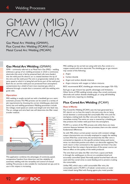
4 <strong>Welding</strong> Processes<strong>GMAW</strong> (<strong>MIG</strong>) /<strong>FCAW</strong> / <strong>MCAW</strong>Gas Metal Arc <strong>Welding</strong> (<strong>GMAW</strong>),Flux Cored Arc <strong>Welding</strong> (<strong>FCAW</strong>) andMetal Cored Arc <strong>Welding</strong> (<strong>MCAW</strong>)Gas Metal Arc <strong>Welding</strong> (<strong>GMAW</strong>)GMA – commonly referred to as Metal Inert Gas (<strong>MIG</strong>) – weldingembraces a group <strong>of</strong> arc welding processes in which a continuouselectrode (the wire) is fed by powered feed rolls (wire feeder)into the weld pool. An electric arc is created between the tip <strong>of</strong>the wire and the weld pool. The wire is progressively melted at thesame speed at which it is being fed and forms part <strong>of</strong> the weld pool.Both the arc and the weld pool are protected from atmosphericcontamination by a shield <strong>of</strong> inert (non-reactive) gas, which isdelivered through a nozzle that is concentric with the welding wireguide tube.Operation<strong>MIG</strong> welding is usually carried out with a handheld gun as a semiautomaticprocess. The <strong>MIG</strong> process can be suited to a variety <strong>of</strong>job requirements by choosing the correct shielding gas, electrode(wire) size and welding parameters. <strong>Welding</strong> parameters includethe voltage, travel speed, arc (stick-out) length and wire feed rate.The arc voltage and wire feed rate will determine the filler metaltransfer method.123456789101 Gun trigger2 <strong>Welding</strong> wire3 Weld4 Weld pool5 Gun6 Shroud7 Gas diffuser8 Contact tip9 Shielding10 DropletsThis application combines the advantages <strong>of</strong> continuity, speed,comparative freedom from distortion and the reliability <strong>of</strong>automatic welding with the versatility and control <strong>of</strong> manualwelding. The process is also suitable for mechanised set-ups, and itsuse in this respect is increasing.<strong>MIG</strong> welding can be carried out using solid wire, flux cored, or acopper-coated solid wire electrode. The shielding gas or gas mixturemay consist <strong>of</strong> the following:■■■■ArgonCarbon dioxideArgon and carbon dioxide mixturesArgon mixtures with oxygen or helium mixtures<strong>BOC</strong> recommends <strong>BOC</strong> shielding gas mixtures (see pages 120–133).Each gas or gas mixture has specific advantages and limitations.Other forms <strong>of</strong> <strong>MIG</strong> welding include using a flux cored continuouselectrode and carbon dioxide shielding gas, or using self-shieldingflux cored wire, requiring no shielding.Flux Cored Arc <strong>Welding</strong> (<strong>FCAW</strong>)How it WorksFlux Cored Arc <strong>Welding</strong> (<strong>FCAW</strong>) uses the heat generated by aDC electric arc to fuse the metal in the joint area, the arc beingstruck between a continuously fed consumable filler wire and theworkpiece, melting both the filler wire and the workpiece in theimmediate vicinity. The entire arc area is covered by a shielding gasthat protects the molten weld pool from the atmosphere.<strong>FCAW</strong> is a variant <strong>of</strong> the <strong>MIG</strong> process and, while there are manycommon features between the two processes, there are also severalfundamental differences.As with <strong>MIG</strong>, direct current power sources with constant voltageoutput characteristics are normally employed to supply the weldingcurrent. With flux cored wires, the terminal that the filler wire isconnected to depends on the specific product being used (somewires run electrode positive and others run electrode negative). Thework return is then connected to the opposite terminal. It has alsobeen found that the output characteristics <strong>of</strong> the power source canhave an effect on the quality <strong>of</strong> the welds produced.The wire feed unit takes the filler wire from a spool, and feedsit through the welding gun, to the arc at a predetermined andaccurately controlled speed. Normally, special knurled feed rolls areused with flux cored wires to assist feeding and to prevent crushingthe consumable.Unlike <strong>MIG</strong>, which uses a solid consumable filler wire, theconsumable used in <strong>FCAW</strong> is <strong>of</strong> tubular construction, an outermetal sheath being filled with fluxing agents plus metal powder.92 AU : IPRM 2007 : Section 4 : <strong>Welding</strong> Processes
<strong>GMAW</strong> (<strong>MIG</strong>) / <strong>FCAW</strong> / <strong>MCAW</strong>4The flux fill is also used to provide alloying, arc stability, slag cover,de-oxidation and, with some wires, gas shielding.In terms <strong>of</strong> gas shielding, there are two different ways inwhich this may be achieved with the <strong>FCAW</strong> process:■■Additional gas-shielding supplied from anexternal source, such as a gas cylinderProduction <strong>of</strong> a shielding gas by decomposition <strong>of</strong>fluxing agents within the wire (self-shielding)Gas shielded wires are available with either a basic or rutile flux fill,while self-shielded wires have a broadly basic-type flux fill. The fluxfill dictates the way the wire performs, the properties obtainable,and suitable applications.Gas-Shielded OperationMany cored wire consumables require an auxiliary gas shield in thesame way that solid wire <strong>MIG</strong> consumables do. These types <strong>of</strong> wireare generally referred to as ‘gas-shielded’.Using an auxiliary gas shield enables the wire designer toconcentrate on the performance characteristics, process tolerance,positional capabilities and mechanical properties <strong>of</strong> the products.In a flux cored wire, the metal sheath is generally thinner than that<strong>of</strong> a self-shielded wire. The area <strong>of</strong> this metal sheath surrounding theflux cored wire is much smaller that than that <strong>of</strong> a solid <strong>MIG</strong> wire.This means that the electrical resistance within the flux cored wireis higher than with solid <strong>MIG</strong> wires and it is this higher electricalresistance that gives this type <strong>of</strong> wire some <strong>of</strong> its novel operatingproperties.One <strong>of</strong>ten quoted property <strong>of</strong> fluxed cored wires are their higherdeposition rates than solid <strong>MIG</strong> wires. What is <strong>of</strong>ten not explainedis how they deliver these higher values and whether these can beutilised. For example, if a solid <strong>MIG</strong> wire is used at 250 amps, thenexchanged for a flux cored wire <strong>of</strong> the same diameter, and weldingpower source controls are left unchanged, then the current readingwould be much less than 250 amps, and perhaps as low as 220 amps.This is because <strong>of</strong> Ohms Law, which states that as the electricalresistance increases (and if the voltage remains stable) then thecurrent must fall.To bring the welding current back to 250 amps, it is necessary toincrease the wire feed speed, effectively increasing the amount <strong>of</strong>wire being pushed into the weld pool to make the weld. It is thiseffect that produces the ‘higher deposition rates’ that the flux coredwire manufacturers claim for this type <strong>of</strong> product. Unfortunately, inmany instances, the welder has difficulty in utilising this higher wirefeed speed and must either increase the welding speed or increasethe size <strong>of</strong> the weld. Often in manual applications, neither <strong>of</strong> thesechanges can be implemented and the welder simply reduces thewire feed speed back to where it was and the advantages are lost.However, if the process is automated in some way, then the processcan show improvements in productivity.It is also common to use longer contact tip to workplace distanceswith flux cored arc welding than with solid wire <strong>MIG</strong> welding, whichhas the effect <strong>of</strong> increasing the resistive heating on the wire furtheraccentuating the drop in welding current. Research has also shownthat increasing this distance can lead to an increase in the ingress<strong>of</strong> nitrogen and hydrogen into the weld pool, which can affect thequality <strong>of</strong> the weld.Flux cored arc welding has a lower efficiency than solid wire <strong>MIG</strong>welding, because part <strong>of</strong> the wire fill contains slag forming agents.Although the efficiency varies by wire type and manufacturer, it istypically between 75 and 85%.Flux cored arc welding does, however, have the same drawback assolid wire <strong>MIG</strong> in terms <strong>of</strong> gas disruption by wind, and screeningis always necessary for site work. It also incurs the extra cost <strong>of</strong>shielding gas, but this is <strong>of</strong>ten outweighed by gains in productivity.Self-Shielded OperationThere are also self-shielded consumables designed to operatewithout an additional gas shield. In this type <strong>of</strong> product, arcshielding is provided by gases generated by decomposition <strong>of</strong> someconstituents within the flux fill. These types <strong>of</strong> wire are referred toas ‘self-shielded’.If no external gas shield is required, then the flux fill mustprovide sufficient gas to protect the molten pool and to providede-oxidisers and nitride formers to cope with atmosphericcontamination. This leaves less scope to address performance, arcstabilisation and process tolerance, so these tend to suffer whencompared with gas shielded types.Wire efficiencies are also lower, at about 65%, in this mode <strong>of</strong>operation than with gas-shielded wires. However, the wires do havea distinct advantage when it comes to site work in terms <strong>of</strong> windtolerance, as there is no external gas shield to be disrupted.Extended self shielded flux cored wire nozzleWhen using self-shielded wires, external gas supply is notrequired and, therefore, the gas shroud is not necessary. However,an extension nozzle is <strong>of</strong>ten used to support and direct thelong electrode extensions that are needed to obtain highdeposition rates.Metal Cored Arc <strong>Welding</strong> (<strong>MCAW</strong>)How It WorksMetal Cored Arc <strong>Welding</strong> (<strong>MCAW</strong>) uses the heat generated bya DC electric arc to fuse metal in the joint area, the arc beingstruck between a continuously fed consumable filler wire and theworkpiece, melting both the filler wire and the workpiece in theimmediate vicinity. The entire arc area is covered by a shielding gas,which protects the molten weld pool from the atmosphere.As <strong>MCAW</strong> is a variant <strong>of</strong> the <strong>MIG</strong> welding process, there are manycommon features between the two processes, but there are alsoseveral fundamental differences.As with <strong>MIG</strong>, direct current power sources with constant voltageoutput characteristics are normally employed to supply the weldingcurrent. With metal cored wires, the terminal that the filler wire isconnected to depends on the specific product being used. (Somewires are designed to run on electrode positive, while others runon electrode negative, and some run on either.) The work returnlead is then connected to the opposite terminal. Electrode negativeoperation will usually give better positional welding characteristics.AU : IPRM 2007 : Section 4 : <strong>Welding</strong> Processes93
4<strong>GMAW</strong> (<strong>MIG</strong>) / <strong>FCAW</strong> / <strong>MCAW</strong>The output characteristics <strong>of</strong> the power source can have an effecton the quality <strong>of</strong> the welds produced.The wire feed unit takes the filler wire from a spool or bulk pack,and feeds it through the welding gun to the arc at a predeterminedand accurately controlled speed. Normally, special knurled feed rollsare used with metal cored wires to assist feeding and to preventcrushing the consumable.Unlike <strong>MIG</strong>, which uses a solid consumable filler wire, theconsumable used in <strong>MCAW</strong> is <strong>of</strong> tubular construction, an outermetal sheath being filled entirely with metal powder, except fora small amount <strong>of</strong> non-metallic compounds. These are added toprovide some arc stability and de-oxidation.<strong>MCAW</strong> consumables always require an auxiliary gas shield in thesame way that solid <strong>MIG</strong> wires do. Wires are normally designed tooperate in argon-carbon dioxide or argon-carbon dioxide-oxygenmixtures or carbon dioxide. Argon-rich mixtures tend to producelower fume levels than carbon dioxide.As with <strong>MIG</strong>, the consumable filler wire and the shielding gas aredirected into the arc area by the welding gun. In the head <strong>of</strong> the gun,the welding current is transferred to the wire by means <strong>of</strong> a copperalloy contact tip, and a gas diffuser distributes the shielding gasevenly around a shroud which then allows the gas to flow over theweld area. The position <strong>of</strong> the contact tip relative to the gas shroudmay be adjusted to limit the minimum electrode extension.Modes <strong>of</strong> metal transfer with <strong>MCAW</strong> are very similar to thoseobtained in <strong>MIG</strong> welding, the process being operable in both ‘diptransfer’ and ‘spray transfer’ modes. Metal cored wires may also beused in pulse transfer mode at low mean currents, but this has notbeen widely exploited.Process Schematic Diagram for <strong>MIG</strong> / <strong>FCAW</strong> and <strong>MCAW</strong>1234Circuit diagram <strong>of</strong> <strong>MIG</strong> processModes <strong>of</strong> Metal Transfer567891011121 Gas hose2 Gas cylinder3 Power source4 Return cable5 Continous wire6 Wire feed unit7 Power cable8 Torch conduit9 <strong>Welding</strong> gun10 Arc11 Workpiece12 Earth clampThe mode or type <strong>of</strong> metal transfer in <strong>MIG</strong> welding depends uponthe current, arc voltage, electrode diameter and type <strong>of</strong> shielding gasused. In general, there are four modes <strong>of</strong> metal transfer.Modes <strong>of</strong> metal transfer with <strong>FCAW</strong> are similar to those obtainedin <strong>MIG</strong> welding, but here the mode <strong>of</strong> transfer is heavily dependenton the composition <strong>of</strong> the flux fill, as well as on current and voltage.The most common modes <strong>of</strong> transfer in <strong>FCAW</strong> are:■■■■Dip transferGlobular transferSpray transferPulsed arc transfer operation has been applied to flux coredwires but, as yet, is not widely used because the other transfermodes are giving users what they require in most cases.Dip TransferAlso known as short-circuiting arc or short-arc, this is an allpositionalprocess, using low heat input. The use <strong>of</strong> relativelylow current and arc voltage settings cause the electrode tointermittently short-circuit with the weld pool at a controlledfrequency. Metal is transferred by the wire tip actually dipping intothe weld pool and the short-circuit current is sufficient to allow thearc to be re-established. This short-circuiting mode <strong>of</strong> metal transfereffectively extends the range <strong>of</strong> <strong>MIG</strong> welding to lower currents sothin sheet material can readily be welded. The low heat input makesthis technique well-suited to the positional welding <strong>of</strong> root runs onthick plate, butt welds for bridging over large gaps and for certaindifficult materials where heat input is critical. Each short-circuitcauses the current to rise and the metal fuses <strong>of</strong>f the end <strong>of</strong> theelectrode. A high short-circuiting frequency gives low heat input. Diptransfer occurs between ±70–220A, 14–23 arc volts. It is achievedusing shielding gases based on carbon dioxide and argon.781 2 3 4 5 6TimeShort circuit cycleSchematic <strong>of</strong> Dip TransferArcing cycle1 Short circuit2 Necking3 Arc re-ignition4 Arc established5 Arc gap shortens6 Short circuit7 Current (A)8 Voltage (V)Metal cored wires transfer metal in dip mode at low currents, justlike solid <strong>MIG</strong> wires. This transfer mode is used for all positionalwork with these types <strong>of</strong> wire.Globular TransferMetal transfer is controlled by slow ejection, resulting in large,irregularly-shaped ‘globs’ falling into the weld pool under the action<strong>of</strong> gravity. Carbon dioxide gas drops are dispersed haphazardly. Withargon-based gases, the drops are not as large and are transferred ina more axial direction. There is a lot <strong>of</strong> spatter, especially in carbondioxide, resulting in greater wire consumption, poor penetrationand poor appearance. Globular transfer occurs between the dip andspray ranges. This mode <strong>of</strong> transfer is not recommended for normalwelding applications and may be corrected when encounteredby either decreasing the arc voltage or increasing the amperage.Globular transfer can take place with any electrode diameter.1 2Schematic <strong>of</strong> Globular Transfer31 Large droplet2 Splatter3 WorkpieceBasic flux cored wires tend to operate in a globular mode or ina globular-spray transfer mode, where larger than normal spraydroplets are propelled across the arc, but they never achieve a truespray transfer mode. This transfer mode is sometimes referred to asnon-axial globular transfer.94 AU : IPRM 2007 : Section 4 : <strong>Welding</strong> Processes
<strong>GMAW</strong> (<strong>MIG</strong>) / <strong>FCAW</strong> / <strong>MCAW</strong>4Self-shielded flux cored wires operate in a predominantly globulartransfer mode, although at high currents the wire <strong>of</strong>ten ‘explodes’across the arc.Spray TransferIn spray transfer, metal is projected by an electromagnetic forcefrom the wire tip in the form <strong>of</strong> a continuous stream <strong>of</strong> discretedroplets approximately the same size as the wire diameter. Highdeposition rates are possible and weld appearance and reliabilityare good. Most metals can be welded, but the technique islimited generally to plate thicknesses greater than 6mm. Spraytransfer, due to the tendency <strong>of</strong> the large weld pool to spillover, cannot normally be used for positional welding. The mainexception is aluminium and its alloys where, primarily because <strong>of</strong>its low density and high thermal conductivity, spray transfer inposition can be carried out.The current flows continuously because the high voltagemaintains a long arc and short-circuiting cannot take place. Itoccurs best with argon-based gases.Pulsed TransferPulsed arc welding is a controlled method <strong>of</strong> spray transfer,using currents lower than those possible with the spray transfertechnique, thereby extending the applications <strong>of</strong> <strong>MIG</strong> welding intothe range <strong>of</strong> material thickness where dip transfer is not entirelysuitable.The pulsed arc equipment effectively combines two powersources into one integrated unit. One side <strong>of</strong> the power sourcesupplies a background current which keeps the tip <strong>of</strong> the wiremolten. The other side produces pulses <strong>of</strong> a higher current thatdetach and accelerate the droplets <strong>of</strong> metal into the weld pool. Thetransfer frequency <strong>of</strong> these droplets is regulated primarily by therelationship between the two currents. Pulsed arc welding occursbetween ±50–220A, 23–35 arc volts, and only with argon and argonbasedgases. It enables welding to be carried out in all positions.123451 Gas shroud2 Wire3 Shielding gas4 Droplets5 Weld6 WorkpieceCurrent (A)3002000Pulsed arc droplets18 ms Time6Schematic for Pulse TransferSchematic <strong>of</strong> Spray TransferIn solid wire <strong>MIG</strong>, as the current is increased, dip transfer passesinto spray transfer via a transitional globular transfer mode. Withmetal cored wires there is virtually a direct transition from diptransfer to spray transfer as the current is increased.For metal cored wire, spray transfer occurs as the current densityincreases and an arc is formed at the end <strong>of</strong> the filler wire,producing a stream <strong>of</strong> small metal droplets. Often the outsidesheath <strong>of</strong> the wire will melt first and the powder in the centre flowsas a stream <strong>of</strong> smaller droplets into the weld pool. This effect seemsto give much better transfer <strong>of</strong> alloying elements into the weld.In spray transfer, as the current density increases, an arc is formedat the end <strong>of</strong> the filler wire, producing a stream <strong>of</strong> small metaldroplets. In solid wire <strong>MIG</strong>, this transfer mode occurs at highercurrents. Flux cored wires do not achieve a completely true spraytransfer mode, but a transfer mode that is almost true spray mayoccur at higher currents and can occur at relatively low currentsdepending on the composition <strong>of</strong> the flux.Rutile flux cored wires will operate in this almost-spray transfermode at all practicable current levels. They are also able to operatein this mode for positional welding. Basic flux cored and selfshieldedflux cored wires do not operate in anything approachingtrue spray transfer mode.ProcessMetal Inert Gas(<strong>MIG</strong>)Flux Cored(Gas Shielded)Flux Cored(Self Shielded)Metal CoredDipTransferGlobularTransferSprayTransferPulsedTransfer● ● ●●●●●NotTrue Spray● ● ●AU : IPRM 2007 : Section 4 : <strong>Welding</strong> Processes95
4<strong>GMAW</strong> (<strong>MIG</strong>) / <strong>FCAW</strong> / <strong>MCAW</strong><strong>MIG</strong>(Carbon steel and alloys)Gas requiredCarbon Dioxide 56Argoshield mixture 60–64Metal Consumables<strong>MIG</strong> wire (carbon steel) 351Other Consumables and AccessoriesAbrasives 512Anti spatter compounds 548Contact tips 274Cylinder trolleys 194Earthing clamps 231<strong>MIG</strong> nozzles and other consumables 274<strong>MIG</strong> torches 259Hoses and fittings 179Machine spares —NDT – dye penetrant sprays —<strong>Welding</strong> cable 232<strong>Welding</strong> screens 639Gas EquipmentRegulator and flowmeter 158Integrated regulator flowmeter —EquipmentFume extractors 631<strong>MIG</strong> machines 234Grinders 496Wire feeder rolls —Wire feeders 257Personal Protective EquipmentAprons —Boots 628Eye protection 604Dust masks 612Ear muffs 609Face shields —Fire extinguishers 640Gloves 616Hand shields and helmets 595Hats and caps —Overalls —Signage —<strong>MIG</strong>(Copper/silicon bronze)Gas requiredSpecshield Copper 70Alushield mixture 67Metal Consumables<strong>MIG</strong> wire (copper/copper alloys) 439Other Consumables and AccessoriesAbrasives 512Anti spatter compounds 548Contact tips 274Cylinder trolleys 194Earthing clamps 231<strong>MIG</strong> nozzles and other consumables 274<strong>MIG</strong> torches 259Hoses and fittings 179Machine spares —NDT – dye penetrant sprays —<strong>Welding</strong> cable 232<strong>Welding</strong> screens 639Gas EquipmentRegulator and flowmeter 158Integrated regulator flowmeter —EquipmentFume extractors 631<strong>MIG</strong> machines 234Grinders 496Wire feeder rolls —Wire feeders 257Personal Protective EquipmentAprons —Boots 628Eye protection 604Dust masks 612Ear muffs 609Face shields —Fire extinguishers 640Gloves 616Hand shields and helmets 595Hats and caps —Overalls —Signage —<strong>MIG</strong>(Stainless steel)Gas requiredStainshield mixture 65–66Metal Consumables<strong>MIG</strong> wire (stainless steel) 406Other Consumables and AccessoriesAbrasives 512Anti spatter compounds 548Contact tips 274Cylinder trolleys 194Earthing clamps 231<strong>MIG</strong> nozzles and other consumables 274<strong>MIG</strong> torches 259Hoses and fittings 179Machine spares —NDT – dye penetrant sprays —Pickling and passivating paste 549<strong>Welding</strong> cable 232<strong>Welding</strong> screens 639Gas EquipmentRegulator and flowmeter 158Integrated regulator flowmeter —EquipmentFume extractors 631<strong>MIG</strong> machines 234Grinders 496Wire feeder rolls —Wire feeders 257Personal Protective EquipmentAprons —Boots 628Eye protection 604Dust masks 612Ear muffs 609Face shields —Fire extinguishers 640Gloves 616Hand shields and helmets 595Hats and caps —Overalls —Signage —96 AU : IPRM 2007 : Section 4 : <strong>Welding</strong> Processes
<strong>GMAW</strong> (<strong>MIG</strong>) / <strong>FCAW</strong> / <strong>MCAW</strong>4<strong>MIG</strong>(Aluminium)Gas requiredArgon 54Alushield mixture 67Metal Consumables<strong>MIG</strong> wire (aluminium) 425Other Consumables and AccessoriesAbrasives 512Anti spatter compounds 548Contact tips 274Cylinder trolleys 194Earthing clamps 231<strong>MIG</strong> nozzles and other consumables 274<strong>MIG</strong> torches 259Hoses and fittings 179Machine spares —NDT – dye penetrant sprays —<strong>Welding</strong> cable 232<strong>Welding</strong> screens 639Gas EquipmentRegulator and flowmeter 158Integrated regulator flowmeter —EquipmentFume extractors 631<strong>MIG</strong> machines 234Grinders 496Wire feeder rolls —Wire feeders 257Personal Protective EquipmentAprons —Boots 628Eye protection 604Dust masks 612Ear muffs 609Face shields —Fire extinguishers 640Gloves 616Hand shields and helmets 595Hats and caps —Overalls —Signage —<strong>FCAW</strong>(Carbon steel)Gas requiredCarbon Dioxide 56Argoshield 52 63Metal Consumables<strong>FCAW</strong> wire (carbon steel) 351Other Consumables and AccessoriesAbrasives 512Anti spatter compounds 548Contact tips 274Cylinder trolleys 194Earthing clamps 231<strong>MIG</strong> nozzles and other consumables 274<strong>MIG</strong> torches 259Hoses and fittings 179Machine spares —NDT – dye penetrant sprays —<strong>Welding</strong> cable 232<strong>Welding</strong> screens 639Gas EquipmentRegulator and flowmeter 158Integrated regulator flowmeter —EquipmentFume extractors 631<strong>MIG</strong> machines 234Grinders 496Wire feeder rolls —Wire feeders 257Personal Protective EquipmentAprons —Boots 628Eye protection 604Dust masks 612Ear muffs 609Face shields —Fire extinguishers 640Gloves 616Hand shields and helmets 595Hats and caps —Overalls —Signage —<strong>FCAW</strong>(Stainless steel)Gas requiredCarbon Dioxide 56Argoshield 52 63Metal Consumables<strong>FCAW</strong> wire (stainless steel) 406Other Consumables and AccessoriesAbrasives 512Anti spatter compounds 548Contact tips 274Cylinder trolleys 194Earthing clamps 231<strong>MIG</strong> nozzles and other consumables 274<strong>MIG</strong> torches 259Hoses and fittings 179Machine spares —NDT – dye penetrant sprays —Pickling and passivating paste 549<strong>Welding</strong> cable 232<strong>Welding</strong> screens 639Gas EquipmentRegulator and flowmeter 158Integrated regulator flowmeter —EquipmentFume extractors 631<strong>MIG</strong> machines 234Grinders 496Wire feeder rolls —Wire feeders 257Personal Protective EquipmentAprons —Boots 628Eye protection 604Dust masks 612Ear muffs 609Face shields —Fire extinguishers 640Gloves 616Hand shields and helmets 595Hats and caps —Overalls —Signage —AU : IPRM 2007 : Section 4 : <strong>Welding</strong> Processes97