Mixing unit ZIP52 2K - Wagner
Mixing unit ZIP52 2K - Wagner
Mixing unit ZIP52 2K - Wagner
- No tags were found...

You also want an ePaper? Increase the reach of your titles
YUMPU automatically turns print PDFs into web optimized ePapers that Google loves.
Translation of the originalOperating Manual<strong>ZIP52</strong> <strong>2K</strong>Edition 04 / 2011<strong>Mixing</strong> <strong>unit</strong><strong>ZIP52</strong> <strong>2K</strong>C_Z2_00001II 2G IIB T4
EDITION 04 /2011PART NO. ZZB025ENG<strong>ZIP52</strong> <strong>2K</strong>.OPERATING MANUALContents1 ABOUT THESE INSTRUCTIONS 51.1 Languages 51.2 Warnings, notes and symbols in these instructions 52 GENERAL SAFETY INSTRUCTIONS 62.1 Safety instructions for the operator 62.1.1 Electrical equipment 62.1.2 Personnel qualifications 62.1.3 A safe work environment 62.2 Safety instructions for staff 62.2.1 Safe handling of WAGNER spray <strong>unit</strong>s 72.2.2 Earth the <strong>unit</strong> 72.2.3 Material hoses 72.2.4 Cleaning 82.2.5 Handling hazardous liquids, varnishes and paints 82.2.6 Touching hot surfaces 82.3 Correct use 82.4 Use in an explosion hazard area 92.4.1 Correct use 92.4.2 Explosion protection identification 92.4.3 Max. surface temperature 92.4.4 Safety regulations 93 PRODUCT LIABILITY AND WARRANTY 113.1 Important notes on product liability 113.2 Warranty 113.3 CE-conformity 124 DESCRIPTION 134.1 Field of application 134.1.1 Using in accordance with the instructions 134.2 Extent of delivery 134.3 Data 134.3.1 Materials of the parts transporting paint 134.3.2 Technical data 144.3.3 Dimensions and connections 154.4 Functioning 165 STARTING UP AND OPERATING 195.1 Installation and connection 195.1.1 Set up the pump 195.1.2 Earthing 205.1.3 Initial flushing 215.2 Start up 225.2.1 Safety regulations 225.2.2 How to start working 245.2.3 Filling with working material 245.3 Work 255.3.1 Spraying 253
EDITION 04 /2011PART NO. ZZB025ENG<strong>ZIP52</strong> <strong>2K</strong>.OPERATING MANUALContents5.3.2 Painting hints 255.3.3 Work stop 255.3.4 Finishing work and cleaning 275.3.5 Filters cleaning operations 285.4 Storing for longer periods of time 286 FAULT LOCATION, MAINTENANCE AND REPAIR 296.1 Trouble shooting and solution 296.2 Maintenance 307 ACCESSORIES 317.1 Accessories 318 SPARE PARTS 358.1 How to order spare parts 358.2 Overview modules 368.3 Connecting pipes 378.3.1 Air pipes 378.3.2 Product pipes <strong>unit</strong> U843.00 388.3.3 Product pipes <strong>unit</strong> U843.00A 398.4 Paint pump 408.5 Flushing solvent pump 438.6 <strong>ZIP52</strong> motor 468.7 Compensator 488.8 <strong>Mixing</strong> head 508.8.1 <strong>Mixing</strong> head <strong>unit</strong> U843.00 508.8.2 <strong>Mixing</strong> head <strong>unit</strong> U843.00A 518.9 Air group 528.9.1 Air group U843.00 528.9.2 Air group U843.00A 538.10 Floor stand 548.10.1 Floor stand U843.00 548.10.2 Floor stand U843.00A 558.11 Antipulsator 564
EDITION 04 /2011PART NO. ZZB025ENG<strong>ZIP52</strong> <strong>2K</strong>.OPERATING MANUAL1 ABOUT THESE INSTRUCTIONS 1.1 LANGUAGES -- ZZB025ENG-- --ZZB025ITA ZZB025SPA-- -- -- --1.2 WARNINGS, NOTES AND SYMBOLS IN THESE INSTRUCTIONS 5
EDITION 04 /2011PART NO. ZZB025ENG<strong>ZIP52</strong> <strong>2K</strong>.OPERATING MANUAL2 GENERAL SAFETY INSTRUCTIONS2.1 SAFETY INSTRUCTIONS FOR THE OPERATOR 2.1.1 ELECTRICAL EQUIPMENT 2.1.2 PERSONNEL QUALIFICATIONS 2.1.3 A SAFE WORK ENVIRONMENT Ensure that the floor of the working area is anti-static in accordance with EN 50053 Part 1§7-2. Ensure that all persons within the working area wear anti-static shoes, e.g. shoes withleather soles. Ensure that during spraying, persons wear anti-static gloves so that they are earthed viathe handle of the spray gun. Customer to provide paint mist extraction systems conforming to local regulations. Ensure that the following components of a safe working environment are available:– Material/air hoses adapted to the working pressure– Personal safety equipment (breathing and skin protection) Ensure that there are no ignition sources such as naked flame, glowing wires or hotsurfaces in the vicinity. Do not smoke.2.2 SAFETY INSTRUCTIONS FOR STAFF 6
EDITION 04 /2011PART NO. ZZB025ENG<strong>ZIP52</strong> <strong>2K</strong>.OPERATING MANUAL2.2.1 SAFE HANDLING OF WAGNER SPRAY UNITSThe spray jet is under pressure and can cause dangerous injuries.Avoid injection of paint or cleaning agents: Never point the spray gun at people. Never reach into the spray jet. Before all work on the <strong>unit</strong>, in the event of work interruptions and functionalfaults:– Switch off the energy/compressed air supply– Secure the spray gun against actuation.– Relieve the pressure from the spray gun and <strong>unit</strong>.– By functional faults: If possible, remove the defect as described inchap. „Trouble shooting“, otherwise apply to an authorised after-sale service point.In the event of skin injuries caused by paint or cleaning agents: Note down the paint or cleaning agent that you have been using. Consult a doctor immediately.Avoid danger of injury through recoil forces: Ensure that you have a firm footing when operating the spray gun. Only hold the spray gun briefly in any one position.2.2.2 EARTH THE UNITElectrostatic charges can occur on the <strong>unit</strong> due to the electrostatic charge and the flowspeed involved in spraying.These can cause sparks and flames upon discharge. Ensure that the <strong>unit</strong> is earthed for every spraying operation. Earth the workpieces to be coated. Ensure that all persons inside the working area are earthed, e.g. that they are wearingantistatic shoes. When spraying, wear antistatic shoes to earth yourself via the spray gun handle.If gloves are used, they must be antistatic2.2.3 MATERIAL HOSES 7
EDITION 04 /2011PART NO. ZZB025ENG<strong>ZIP52</strong> <strong>2K</strong>.OPERATING MANUAL2.2.4 CLEANING 2.2.5 HANDLING HAZARDOUS LIQUIDS, VARNISHES AND PAINTS 2.2.6 TOUCHING HOT SURFACES 2.3 CORRECT USE 8
EDITION 04 /2011PART NO. ZZB025ENG<strong>ZIP52</strong> <strong>2K</strong>.OPERATING MANUAL2.4 USE IN AN EXPLOSION HAZARD AREA2.4.1 CORRECT USE 2.4.2 EXPLOSION PROTECTION IDENTIFICATIONAs defined in the Directive 94/9/CE (ATEX 95), the <strong>unit</strong> is suitable for use in areas wherethere is an explosion hazard.II 2G IIB T4CE: Communautés EuropéennesEx: Symbol for explosion protectionII: Unit class II2: Category 2 (Zone 1)G: Ex-atmosphere gasIIB: Explosion classT4: Temperature class: maximum surface temperature < 135°C; 275°F.2.4.3 MAX. SURFACE TEMPERATUREMax. surface temperature:same as the permissible material temperaturePermissible ambient temperature: see under Technical data, Section 4.3.22.4.4 SAFETY REGULATIONSSafe handling of WAGNER spray <strong>unit</strong>sThe maximum surface temperature of the pump can be reached if it runs dry. Ensure that the pump is filled with sufficient working or cleaning medium.Mechanical sparks can form if the <strong>unit</strong> comes into contact with metal.In an explosive atmosphere: Do not knock or push the <strong>unit</strong> against steel or rusty iron. Do not drop the <strong>unit</strong>. Use only tools that are made of a permitted material.Ignition temperature of the pumped material Check that the ignition temperature of the pumped material is higher thanthe max. allowable surface temperature.Medium supporting atomizing To atomize the material, use only weakly oxidizing gases, e.g. air.9
EDITION 04 /2011PART NO. ZZB025ENG<strong>ZIP52</strong> <strong>2K</strong>.OPERATING MANUAL 10
EDITION 04 /2011PART NO. ZZB025ENG<strong>ZIP52</strong> <strong>2K</strong>.OPERATING MANUAL3 PRODUCT LIABILITY AND WARRANTY3.1 IMPORTANT NOTES ON PRODUCT LIABILITY 3.2 WARRANTY 11
EDITION 04 /2011PART NO. ZZB025ENG<strong>ZIP52</strong> <strong>2K</strong>.OPERATING MANUAL3.3 CE-CONFORMITYHerewith we declare that the supplied version of:Pneumatic pumps with article no.Part no.ModelU843.00 Pump <strong>ZIP52</strong> <strong>2K</strong> with flushing pumpU843.00A Pump <strong>ZIP52</strong> <strong>2K</strong> without flushing pumpComplies with the following provisons applying to it2006/42/CE94/9/CE AtexApplied standards, in particular:UNI EN ISO 12100-1 UNI EN 809 UNI EN 1127-1UNI EN ISO 12100-2 UNI EN 14121-1 EN 12621UNI EN 563 UNI EN ISO 3746 UNI EN ISO 13463Marking:II 2G IIB T4 ZDI.2112
EDITION 04 /2011PART NO. ZZB025ENG<strong>ZIP52</strong> <strong>2K</strong>.OPERATING MANUAL4 DESCRIPTION4.1 FIELD OF APPLICATION4.1.1 USING IN ACCORDANCE WITH THE INSTRUCTIONSThe pneumatic diaphragm pump is suitable for process liquid materials.SIHC_0067_GBCAUTIONAbrasive fluids and pigments !Greater wear of the parts carrying the material. Use suitable pump model (delivery per cycle, material, valves, etc.)see chapter 4.3.2. Verify that fluids and solvents used are compatible with the constrution materialof the pump as described in chapter 4.3.1.4.2 EXTENT OF DELIVERY<strong>Mixing</strong> <strong>unit</strong> with 1:1 fixed ratio, with pneumatic diaphragm pump composed of:- Diaphragm pump with independent sections- Flushing diaphragm pump (if expected)- Connection elementsCE-conformity see Chapter 3Operating manual in englishPart No. : ZZB025ENGOperating manual for the other language see Chapter 1The delivery note shows the exact scope of delivery.Accessories: see chapter 7.4.3 DATA4.3.1 MATERIALS OF THE PARTS TRANSPORTING PAINTPump bodyDiaphragmsValves ballsValves seatsO-ringsAntipulsatorsConnectionsAluminiumUHMW-PE / PTFEStainless steelStainless steelPTFE / EPDMNickel-plated steelNickel-plated steel/brass13
EDITION 04 /2011PART NO. ZZB025ENG<strong>ZIP52</strong> <strong>2K</strong>.OPERATING MANUAL4.3.2 TECHNICAL DATADescription Units <strong>ZIP52</strong> <strong>2K</strong>Pressure ratio 1:1<strong>Mixing</strong> ratio (in volume) 1:1Flow volume per double stroke (DS) cm³ 65Max. operating pressure (Pump)MPabarpsi0.88116Max. possible strokes in operationDS/minDC/min60Min. - Max. air inlet pressureMPabarpsi0.88116Ø air inlet connection (female) BSP 1/4“Sound pressure with 5 bar feeding air anddB(A) 7650 DS/min (LqA) frequency*Material outlet connection BSP 1/4“WeightModel with flushing pump cod. U843.00Model without flushing pump cod. U843.00Akg; lb 30; 66,226; 57,3Range of material temperature °C; F +5° ÷ +80°; (+41 ÷ +176)Range of the ambient temperature °C; F +4° ÷ +40° ; (+39 ÷ +104)Allowable sloping position at work
EDITION 04 /2011PART NO. ZZB025ENG<strong>ZIP52</strong> <strong>2K</strong>.OPERATING MANUAL4.3.3 DIMENSIONS AND CONNECTIONS<strong>ZIP52</strong> <strong>2K</strong>mm; inchA 470; 18,50B 440; 17,32C 1100; 43,31D BSP 1/4” ME BSP 1/4” MCEDU843.00AC_Z2_00002BCEU843.00ADAC_Z2_00003B15
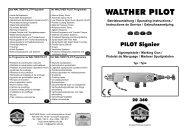
EDITION 04 /2011PART NO. ZZB025ENG<strong>ZIP52</strong> <strong>2K</strong>.OPERATING MANUAL4.4 FUNCTIONING14ca715581011126b93124C_Z2_0000413UNIT <strong>ZIP52</strong>-<strong>2K</strong> - Model with flushing pump cod. U843.00a Paint pump 7 A-component solvent valveb Flushing solvent pump 8 B-component solvent valvec Compensator 9 Main air on-off valve1 A-component suction pipe 10 Paint pump air pressure2 B-component suction pipe 11 Flushing pump air pressure3 A-comp. return pipe 12 Atomising air pressure4 B-comp. return pipe 13 Solvent suction pipe5 A-component recycling valve 14 A-component antipulsator6 B-component recycling valve 15 B-component antipulsator16
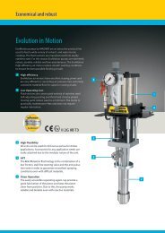
EDITION 04 /2011PART NO. ZZB025ENG<strong>ZIP52</strong> <strong>2K</strong>.OPERATING MANUALc14a1553101246912C_Z2_00005UNIT <strong>ZIP52</strong>-<strong>2K</strong> - Model without flushing pump cod. U843.00Aa Paint pump 9 Main air on-off valvec Compensator 10 Paint pump air pressure1 A-component suction pipe 12 Atomising air pressure2 B-component suction pipe 14 A-component antipulsator3 A-comp. return pipe 15 B-component antipulsator4 B-comp. return pipe5 A-component recycling valve6 B-component recycling valve17
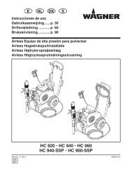
EDITION 04 /2011PART NO. ZZB025ENG<strong>ZIP52</strong> <strong>2K</strong>.OPERATING MANUALGeneral informationFluid section – Pump and compensatorThis <strong>unit</strong> has been designed to proportionate and pumptwo components (A) and (B) separately, with a 1:1 mixingratio, avoiding the frequent and expensive maintenancerequired by piston mixing <strong>unit</strong>s, since the paints have a highcontent of extenders or coarse pigments.The working principle is both simple and effective: it isbased on a diaphragm pump with independent pumpingchambers, driven by compressed air.Two diaphragms (A 1- A ) connected through the shaft (B)2divide two independent and adjoining volumes into fourchambers. The two inner chambers are the driving chambers(C 1-C 2) while the outer chambers are the pumping ones (D 1-D 2); a pneumatic distributor conveys the compressed airalternatively into the first or the second driving chamber(C 1-C 2), provoking the diaphragm displacement and thefollowing emptying of one of the pumping chamber (dueto volume reduction) as well as the contemporary fillingof the other pumping chamber (due to volume increase);a series of check valves (E) prevents the fluid flowing back,caused by the suction and delivery phase in each pumpingchamber.A compensator (F) composed of two chambers (G 1-G 2) and(H) separated by a diaphragm, is assembled directly on thepump delivery inlets.During the given phase (shaft displacement to the right),the chamber (G 2) will be filled with a volume increase thatwill move the diaphragm (H) to the left and consequentlythe chamber (G 1) will be emptied (with a volume decrease).Due to the system pressure drop, part of the fluid pumpedinto the chamber (G 1) will flow into the mixer, automaticallymaking up for the lack of the component which is notpumped during this phase; also in this case, a series of checkvalves (E) prevents the liquid re-flowing.This phase is followed by a symmetric one.EFHG 1 G 2D 1D 2C 1 – C 2EBA 1 – A 2 18
EDITION 04 /2011PART NO. ZZB025ENG<strong>ZIP52</strong> <strong>2K</strong>.OPERATING MANUAL5 STARTING UP AND OPERATING5.1 INSTALLATION AND CONNECTION5.1.1 SET UP THE PUMP1. Place the pump on a flat and horizontal surface.2. Connect the double product/air pipe and the spraying gun, paying attention not toreverse the atomizing air pipe with the product pipe.WARNINGDischarge of electrostatically charged components in atmospherescontaining solvents!Explosion hazard from electrostatic sparks. Clean the pump only with a damp cloth.SIHC_41_0041_GBWARNINGInclined surface!Risk of accidents if the <strong>unit</strong> rolls away/falls. Place the frame with the pump horizontally. Lock the frame.SIHC_41_0012_GB19
EDITION 04 /2011PART NO. ZZB025ENG<strong>ZIP52</strong> <strong>2K</strong>.OPERATING MANUAL5.1.2 EARTHING Earthing schema (example)ConveyorWorkpieceSpraying stand ΩPaint containerAnti-static floor20
EDITION 04 /2011PART NO. ZZB025ENG<strong>ZIP52</strong> <strong>2K</strong>.OPERATING MANUAL5.1.3 INITIAL FLUSHING1. Turn off completely the atomising air on the spraying gun. Please refer to the manual.2. Put the suction pipes (1 and 2) with their recycling pipes into a container filled withsolvent.3. Turn on the recycling valves (5 and 6) and make sure the solvent valves (7 and 8) areclosed (if any – models with flushing pump).4. Slowly open the ball valve (9).5810693124C_Z2_000065. Adjust the pressure regulator (10) until the pump starts working.6. Wait until the solvents comes out from both the recycling pipes (3 and 4).7. Turn off the recycling valves (5 and 6).8. Point the gun to the solvent container and turn it on.Warning: risk of material‘s sprayback! Protect body and eyes!9. Wash the system until clean solvent comes out from the gun.10. Turn off the ball valve (9) and depressurise the motor, pulling the gun trigger into thesolvent container.11. When the system is depressurized, close the spray gun.12. Dispose of the container content in compliance with the local regulations in force.21
EDITION 04 /2011PART NO. ZZB025ENG<strong>ZIP52</strong> <strong>2K</strong>.OPERATING MANUAL5.2 START UP5.2.1 SAFETY REGULATIONSEvery time before starting up the following points should be observed as laid down in theoperating instructions:- That it is possible to observe the safety regulations in Chap. 2.- The starting up procedure, has been carried out properly. WARNINGGas mixtures can explode if there is an incompletely filledpump!Danger to life from flying parts. Ensure that the pump and suction system are alwayscompletely filled with cleaning agent or working medium. Do not spray the <strong>unit</strong> empty after cleaning.SIHI_41_0025_GB22
EDITION 04 /2011PART NO. ZZB025ENG<strong>ZIP52</strong> <strong>2K</strong>.OPERATING MANUALBefore every start-up, the following points should be observed as laid down in the operatingmanual:- Make sure the gun is turned off- Check the permissible pressures- Check all connections for leaks- Check hose for damageIt should be ensured that the <strong>unit</strong> is in the following state before carrying out any work onit:- Depressurise the pump and the gun hose- Make sure the gun is turned off- The air supply should be interrupted5C_Z2_0000769Emergency stopIn the case of unforeseen occurrences close immediately the ball valve (9) and depressurisethe pump opening the gun or the recycling valves (5 and 6).During operation the pump must be in vertical position.23
EDITION 04 /2011PART NO. ZZB025ENG<strong>ZIP52</strong> <strong>2K</strong>.OPERATING MANUAL5.2.2 HOW TO START WORKINGTips to prepare accelerated/catalysed polyester paints.Prepare two containers. Put half of the paint to be used into the first container, and theother half in the second container.In case of a total quantity of 10 litres, put the accelerator required for all the 10 litres into acontainer and the catalyst required to catalyse all the 10 litres into the other container.EXAMPLE: if a paint is to be catalysed at 2% and accelerated at 2% and 10 litres of paint aregoing to be prepared, put 5 litres into the first container and 5 litres into the second one.Put the 200cc of accelerator into container A and 200cc of catalyst into container B.Mix well the content of the two containers making sure to use different tools, to avoidmixing accelerator traces with catalysed resin and vice-versa.5.2.3 FILLING WITH WORKING MATERIALTurn off the gun atomising air. Please refer to the gun manual.Plunge the A-component suction pipe into the A-component container and the B-component suction pipe into the B-component container.WARNING : Never reverse the suction pipes of the two components to avoid the risk ofproduct hardening inside the equipment.Place the valves (5) and (6) on the recycling.Open slowly the ball valve (9) of motor feeding air.Adjust the pressure regulator (10) until the pump starts working.Point the gun without nozzle to the waste container.Warning: risk of material‘s sprayback! Protect body and eyes!Acting on the pressure regulator (10), adjust the air pressure so that the pump can cycleregularly.When pure material is delivered without air bubbles, close the ball valve (9) and depressurizethe motor by pushing the gun trigger directing it towards the container.When the system is depressurized, close the spray gun.Dispose of the container content in compliance with the local regulations.24
EDITION 04 /2011PART NO. ZZB025ENG<strong>ZIP52</strong> <strong>2K</strong>.OPERATING MANUAL5.3 WORK5.3.1 SPRAYINGWait until the two pumps are perfectly charged and make sure no air bubbles are comingout from the recycling (3) and (4).Make sure the recycling valves (5 and 6 ) are closed.Keep the gun open on a container used for the washing solvent (waste container) until allthe solvent contained into the pipes comes out and the mixed paint starts flowing.Adjust the motor air pressure (10) to the required value to have a good product supply.Pressure shall be proportional to product viscosity and to the size of the nozzle used forthe gun.Adjust the atomising air pressure to 1,5-2 bar, using the regulator (12). Also in this case, thenecessary pressure shall be proportional to the viscosity of the product being used.Adjust the fan width according to the needs and start painting.5.3.2 PAINTING HINTSIf the pump speeds up suddenly and starts to shake, it means that there is no paint leftinside it and that it is sucking air. You must therefore supply it with new paint. If the pumpstarts shaking like it would do if there were no paint left (but in fact there is), you mustclean the suction pipes filters (see the “Filter cleaning operations” paragraph).If the pump works asymmetrically, with a fast phase and a slow phase, it means that one ofthe components has finished. A filling up is therefore required.WARNING:Every time painting is stopped, close the motor air valve (9x) and at the same timeput valves (5 and 6) in recycling position, to discharge pressure.5.3.3 WORK STOP1. Close spray gun.2. Close ball valve (9).3. Depressurise the system opening the recycling valves (5 and 6).4. Clean the equipment as described below, to prevent the mixed product from catalysinginto the circuit, blocking the equipment.25
EDITION 04 /2011PART NO. ZZB025ENG<strong>ZIP52</strong> <strong>2K</strong>.OPERATING MANUALIntermediate flushing – Only for models with flushing pump1. If painting is to be interrupted for a time similar to the reaction time of the productbeing used (always refer to the technical characteristics provided by the manufacturer),an intermediate flushing must be carried out, in the following way:2. Close the motor feeding air (9).3. Put the levers of A-component valve (5) and B-component valve (6) in recyclingposition.4. Close the atomising air (12), open the gun on the waste container and keep it open,open the washing solvent valves (7 and 8) alternatively and repeatedly, until cleansolvent comes out.5. To resume work, make sure the washing solvent valves (7 and 8) are closed; open themotor feeding air valve (9) to start up the pump and let each product recycle, makingsure there are no air bubbles coming out from the recycling.6. As soon as the pumps are properly primed, put at the same time the two levers of therecycling valves (5 and 6) in working position.7. Open the gun on the waste container and wait until the mixed paint comes out.8. Open the atomising air (11). Now the original working conditions have been restored.Warning : In case of models without flushing pump, use the final flushing procedurealso for these short interruptions.Final flushing – for all models.Wash carefully the equipment at the end of each job.After painting, close the motor feeding air (9).Put the levers of A-component (5) and of B-component (6) valves in recycling position.Reduce the motor feeding pressure to 1,5 – 2 bar, using the regulator (10).Close the atomising air (12).Open the motor air valve (9).Lift the suction pipes of the 2 components (1) and (2) from their containers and afteremptying the pumps, plunge them into the solvent containers. Let them recycle for abouta minute.Put the valves (5) and (6) in working position, keep the gun open and, if necessary, increasethe motor feeding pressure, then let it recycle for a few minutes until clean solvent comesout.Close the motor feeding air (9).Only for models with flushing pump:Keep the gun open on the waste container, open the washing solvent valves (7) and (8)alternatively and repeatedly, until clean solvent comes out.Close the gun, put it on the washing solvent container, re-open it and let it recycle for abouta minute. Close the gun.Close the washing solvent valves (7) and (8).NOTE: After using it, it is necessary to leave the equipment full of solvent; any paint residueleft after a hasty washing cannot harden and shall be discharged when resuming work.The filters shall be cleaned at the end of each job.26
EDITION 04 /2011PART NO. ZZB025ENG<strong>ZIP52</strong> <strong>2K</strong>.OPERATING MANUAL 5.3.4 FINISHING WORK AND CLEANINGNoteThe device should be cleaned for maintenance purposes, etc. Ensure that no remainingmaterial dries and sticks.Procedure:1. Working breaks -> procedure on chapter 5.3.3.2. Carry out the initial flushing operations ->procedure on chapter 5.1.3.3. Maintain the gun as laid down in the operating instructions.4. Clean and check the suction system and, in particular, the suction filter (see instructionsbelow).5. Clean and check the filtering cartridge of the antipulsators (see instructions below).6. Clean the outside of the system.7. Put the whole system back together.8. Fill the equipment with solvent as described in paragraph 5.2.3 „Filling with workingmaterial“.SIHI_41_0025_GBWARNINGGas mixtures can explode if there is an incompletely filledpump!Danger to life from flying parts. Ensure that the pump and suction system are alwayscompletely filled with cleaning agent or working medium. Do not spray the <strong>unit</strong> empty after cleaning.27
EDITION 04 /2011PART NO. ZZB025ENG<strong>ZIP52</strong> <strong>2K</strong>.OPERATING MANUAL5.3.5 FILTERS CLEANING OPERATIONSWARNING:Before you clean the filters, you must close the compressed air input valve and releasethe pressure contained inside the pump and the pipes attached to it.The equipment is supplied with filters on both suction and delivery pipes.ALL FILTERS MUST BE CLEANED DAILY.IT IS ALSO NECESSARY TO CLEAN THEM WHEN USING A DIFFERENT COLOUR PAINTFROM THE ONE PREVIOUSLY USED.To clean the filter of suction pipes (1), (3) and (13 if any) in models with flushing pump–loosen the spring, remove the filtering disk and put it into the solvent, then brush it andblow with compressed air.To clean the antipulsators filters (14) and (15), unscrew the cap and the locking nut, removethe filtering cartridge and put it into the solvent, then brush it and blow with compressedair. Make sure to clean also the filter inside part with solvent; if necessary, blow it withcompressed air.WARNING: Protect the eyes from any solvent splash.When reassembling the filter, make sure to position correctly the gasket.5.4 STORING FOR LONGER PERIODS OF TIMEWhen storing the device for longer periods of time it is necessary to thoroughly clean itand protect it from corrosion. Replace solvent in the material pump with a suitable preservingoil. Fill separating fluid cup with separating fluid.Procedure:1. Carry out Paragraph 5.3.4 “Finishing work and cleaning“, points 1 through 8.2. Cleaning with preserving agent acc. Paragraph 5.1.3.3. Protect the air motor with pneumatic oil: connect an oiler to the compressed air inletand run for a few double strokes.28
EDITION 04 /2011PART NO. ZZB025ENG<strong>ZIP52</strong> <strong>2K</strong>.OPERATING MANUAL6 FAULT LOCATION, MAINTENANCE AND REPAIR6.1 TROUBLE SHOOTING AND SOLUTIONProblem Cause SolutionThe pump does notworkThe pump works butthe paints does notarrive to the gun andrecyclingThe paint comes outfrom the gun with adiscontinuous flowPaint flow rate is poorand does not varyincreasing the feedingpressureAbnormal catalyst(anomalous dosing)• Lack of air pressure to the pump(no reading on the manometer)• The pressure regulator doesnot work (no reading on themanometer)• The pump pneumatic motor doesnot start up• Insufficient supply of compressedair• Clogged circuit filters• Clogged suction valves and/orpipes• Air infiltration in suction circuits• Partially clogged filters• Too high paint viscosity• Partially clogged suction pipefilters• Air infiltration from suction pipes• Tightness problems of diaphragmpump valvesIf the problem is not listed above consult your WAGNER Service Center.• Check the pressure in the feeding aircircuit• Repair or replace the pressure regulator• Close/open the air valve to the pump ortemporary cut the compressed air feeding• Check compressed air supply• Check the suction pipe filters, clean themcarefully and replace them• Make sure the suction pipes or valves arenot clogged by hardened paint residue• Make sure there are no air infiltrations(tightening clamps, fittings, etc.)• Check and clean the filters• Dilute the paint according tomanufacturer’s instructions• Check and clean the suction pipe filters• Make sure there are no air infiltrations(tightening clamps, fittings, etc.)• Check the diaphragm pump valves.Replace if necessary29
EDITION 04 /2011PART NO. ZZB025ENG<strong>ZIP52</strong> <strong>2K</strong>.OPERATING MANUAL6.2 MAINTENANCE 1. Check and clean the delivery and suction filters every day or whenever necessary.2. Every shut down should be carried out as laid down in paragraph 5.3.4!3. Check and replace if necessary hoses, tubes, couplings every days.WAGNER recommends to check the whole spray system every year from a technical expert(e.g. WAGNER service technician).30
EDITION 04 /2011PART NO. ZZB025ENG<strong>ZIP52</strong> <strong>2K</strong>.OPERATING MANUAL7 ACCESSORIES7.1 ACCESSORIES8733114542 5631C_Z2_0001931
EDITION 04 /2011PART NO. ZZB025ENG<strong>ZIP52</strong> <strong>2K</strong>.OPERATING MANUALList accessories<strong>ZIP52</strong> <strong>2K</strong>Pos K DescriptionNo1 Stainless steel ST suction hose T406.002 Suction pipe ST compl. met. part T420.003 Flexible pipe holder M208.044 SSt contact clip E0107.035 Hose clamp R601.006 Solvent resistant suction hose S402.00A7 Double pipe PE 6x8 - 7,5 mt. with sheathing S419.00G7 Double pipe PE 6x8 - 10 mt. with sheathing S419.00GA8 SP5 manual gun - mm. 0,8 R950.088 SP5 manual gun - mm. 1,0 R950.108 SP5 manual gun - mm. 1,2 R950.128 SP5 manual gun - mm. 1,5 R950.158 SP5 manual gun - mm. 1,8 R950.1832
EDITION 04 /2011PART NO. ZZB025ENG<strong>ZIP52</strong> <strong>2K</strong>.OPERATING MANUAL33
EDITION 04 /2011PART NO. ZZB025ENG<strong>ZIP52</strong> <strong>2K</strong>.OPERATING MANUAL34
EDITION 04 /2011PART NO. ZZB025ENG<strong>ZIP52</strong> <strong>2K</strong>.OPERATING MANUAL8 SPARE PARTS8.1 HOW TO ORDER SPARE PARTS 35
EDITION 04 /2011PART NO. ZZB025ENG<strong>ZIP52</strong> <strong>2K</strong>.OPERATING MANUAL8.2 OVERVIEW MODULESU843.00 U843.00APos Description See pag. See pag.a Paint pump Pag. 40 Pag. 40b Flushing solvent pump Pag. 43 Pag. 43c Compensator Pag. 48 Pag. 48d <strong>Mixing</strong> head Pag. 50 Pag. 51e Air group Pag. 52 Pag. 53f Floor stand Pag. 54 Pag. 55g Antipulsator Pag. 56 Pag. 56h Suction pipe Pag. 31 Pag. 31ccaagedhhgedhhggfbhC_Z2_0000836
EDITION 04 /2011PART NO. ZZB025ENG<strong>ZIP52</strong> <strong>2K</strong>.OPERATING MANUAL8.3 CONNECTING PIPES8.3.1 AIR PIPESU843.0012U843.00A4 41C_Z2_00020Air pipesUnits U843.00 - U843.00APos Description Q.ty (*) No.1 Hose nylon d.8 black 300 mm S103.07N2 Hose nylon d.8 black 420 mm S103.07N(*) Unit total quantity37
EDITION 04 /2011PART NO. ZZB025ENG<strong>ZIP52</strong> <strong>2K</strong>.OPERATING MANUAL8.3.2 PRODUCT PIPES UNIT U843.004335221 1C_Z2_00021Product pipes <strong>unit</strong> U843.00Pos Description Q.ty No.1 Antipulsator feeding pipe 2 S468.002 Delivery pipe to mixing head 2 S468.00A3 Recycling pipe 2 S468.00B4 Washing valves connecting pipe 1 S468.00C5 Washing delivery pipe 1 S468.00D38
EDITION 04 /2011PART NO. ZZB025ENG<strong>ZIP52</strong> <strong>2K</strong>.OPERATING MANUAL8.3.3 PRODUCT PIPES UNIT U843.00A33221 1C_Z2_00022Product pipes <strong>unit</strong> U843.00APos Description Q.ty No.1 Antipulsator feeding pipe 2 S468.002 Delivery pipe to mixing head 2 S468.00A3 Recycling pipe 2 S468.00B39
EDITION 04 /2011PART NO. ZZB025ENG<strong>ZIP52</strong> <strong>2K</strong>.OPERATING MANUAL8.4 PAINT PUMP1075211386419C_Z2_00009Spare parts listPaint pumpPos K Description Q.ty No.1 M6 low self-locking nut 4 K311.62A2 Sleeve 1/4 1 M279.003 <strong>ZIP52</strong> pump ind/ind 1 U551.ATSS84 Flexible pipe holder G1/2 2 M208.045 Fast swivel fitting L 1/4x8 1 M336.006 L-shaped fitting MF 1/2 2 M217.047 Washer d.6 4 K505.628 <strong>ZIP52</strong> pump’s bracket 1 E3384.629 Antipulsator’s bracket 2 E3388.6210 Socket screw M6x20 4 K107.6211 Loctite 542 - -40
EDITION 04 /2011PART NO. ZZB025ENG<strong>ZIP52</strong> <strong>2K</strong>.OPERATING MANUAL85 Nm; 3.7 lbft3.5 Nm; 2.5 lbft13202232417654211218141112 Nm; 8.8 lbft31091925 26271122155 Nm; 3.7 lbftC_Z2_0002475 Nm; 3.7 lbft41
EDITION 04 /2011PART NO. ZZB025ENG<strong>ZIP52</strong> <strong>2K</strong>.OPERATING MANUALSpare parts list<strong>ZIP52</strong> pump ind/indU551.ATSS8Pos K Description Q.ty No.1 Suction manifold 2 F184.01D2 Delivery manifold 2 F185.01D3 Outer diaphragm disk 2 F834.07R4 Diaphragm cover 2 F978.015 Product diaphragm 2 G921.056 Support diaphragm 2 G921.067 Socket screw M6x35 4 K142.628 Socket screw M6x30 4 K183.629 Self-locking nut M6 16 K311.6210 Washer 6 20 K505.6211 Self-tapping screw 1 K1012.6212 Screw 4 K1040.6213 Rivet 2 K1041.6214 Screw 12 K1044.6215 Self-locking nut M6 8 K311.62A16 -17 Motor 1 T6103.00S18 Fluid valve <strong>unit</strong> 4 T6105.0019 Lug 1 Y622.00A20 Cover plate 1 Z535.00X21 Side plate -22 Cover round plate 2 Z543.00A23 Nipple 1 B0177.14A24 Contact washer 4 K564.7225 Ball 4 K805.0326 Ball seat 4 B0148.03A27 O-ring 4 L206.05Product o-ring set 1 T9077.00Fluid service set 1 T9080.00 = Wearing parts = Included in service set42
EDITION 04 /2011PART NO. ZZB025ENG<strong>ZIP52</strong> <strong>2K</strong>.OPERATING MANUAL8.5 FLUSHING SOLVENT PUMP61087254311981C_00010Spare parts listFlushing solvent pumpPos K Description Q.ty No.1 Low self-locking nut M6 4 K311.622 Sleeve 1/4 1 M279.003 <strong>ZIP52</strong> pump universal 1 U550.ATSS74 Flexible pipe holder G1/2 1 M208.045 Fast swivel fitting L L 1/4x8 1 M336.006 L-shaped fitting MM 1/4 1 M215.047 Reduction MF 1/2x1/4 1 M247.008 Washer d.6 8 K505.629 <strong>ZIP52</strong> pump’s bracket 1 E3384.6210 Socket screw M6x20 4 K107.6211 Loctite 542 - -43
EDITION 04 /2011PART NO. ZZB025ENG<strong>ZIP52</strong> <strong>2K</strong>.OPERATING MANUAL8165 Nm; 3.7 lbft23.5 Nm; 2.5 lbft24132025 262723176542112181412 Nm; 8.8 lbft113221091915 Nm; 3.7 lbft157C_Z2_000255 Nm; 3.7 lbft44
EDITION 04 /2011PART NO. ZZB025ENG<strong>ZIP52</strong> <strong>2K</strong>.OPERATING MANUALSpare parts list<strong>ZIP52</strong> pump universalU550.ATSS7Pos K Description Q.ty No.1 Suction manifold 1 F184.01C2 Delivery manifold 1 F185.01C3 Outer diaphragm disk 2 F834.07R4 Diaphragm cover 2 F978.015 Product diaphragm 2 G921.056 Support diaphragm 2 G921.067 Socket screw M6x35 4 K142.628 Socket screw M6x30 4 K183.629 Self-locking nut M6 16 K311.6210 Washer 6 20 K505.6211 Self-tapping screw 1 K1012.6212 Screw 4 K1040.6213 Rivet 2 K1041.6214 Screw 12 K1044.6215 Self-locking nut M6 8 K311.62A16 Plug 1/2 4 M254.14A17 Motor 1 T6103.0018 Fluid valve <strong>unit</strong> 4 T6105.0019 Lug 1 Y622.00A20 Cover plate 1 Z535.00X21 Side plate -22 Cover round plate 2 Z543.00A23 Nipple 1 B0177.1424 Contact washer 4 K564.7225 Ball 4 K805.0326 Ball seat 4 B0148.03A27 O-ring 4 L206.05Product o-ring set 1 T9077.00Fluid service set 1 T9080.00 = Wearing parts = Included in service set45
EDITION 04 /2011PART NO. ZZB025ENG<strong>ZIP52</strong> <strong>2K</strong>.OPERATING MANUAL8.6 <strong>ZIP52</strong> MOTOR2 Nm; 1.47 lbft1149215312138712 Nm; 1.47 lbft1417516106C_Z2_0002346
EDITION 04 /2011PART NO. ZZB025ENG<strong>ZIP52</strong> <strong>2K</strong>.OPERATING MANUAL Spare parts list<strong>ZIP52</strong> motor T6103.00 T6103.00SPos K Description Q.ty No. No.1 Feeler pin 2 B0146.04 B0146.042 Inner diaphragm disk 2 B0147.71 B0147.713 Shaft 1 B0150.03 B0150.03S4 Cover (pressure side) 1 F194.91 F194.915 Bushing guide rod 2 F829.07 F829.076 Cover (discharge side) 1 F830.07 F830.077 Motor block with safety valve 1 T6103.00A T6103.00A8 Reversing valve gasket 1 G925.06 G925.069 Pressure cover gasket 1 G7020.06 G7020.0610 Silencer 1 H618.07 H618.0711 Screw 4 K1038.62 K1038.6212 Screw 6 K1039.62 K1039.6213 Lip gasket 2 L470.06 L470.0614 Lip gasket 2 L471.06 L471.0615 Reversing valve (*) 1 P4003.00 P4003.0016 Safety valve (**) 1 see pos. 7 see pos. 717 Side plate 1 Z546.00 Z546.00Fluid service set 1 T9080.00 T9080.00(*) Includes pos. 8 and 9(**) Not available separately = Wearing parts = Included in service set47
EDITION 04 /2011PART NO. ZZB025ENG<strong>ZIP52</strong> <strong>2K</strong>.OPERATING MANUAL8.7 COMPENSATOR5 Nm; 3.7 lbft165 Nm; 3.7 lbft5141219639115 Nm; 3.7 lbft131075 Nm; 3.7 lbft4155 Nm; 3.7 lbft18218C_Z2_0001117195 Nm; 3.7 lbft48
EDITION 04 /2011PART NO. ZZB025ENG<strong>ZIP52</strong> <strong>2K</strong>.OPERATING MANUAL Spare parts listCompensatorPos K Description Q.ty No.1 Compensator supporting carter 1 E3387.622 Suction manifold <strong>ZIP52</strong> independent 2 F184.01D3 Delivery manifold <strong>ZIP52</strong> independent 2 F185.01D4 <strong>ZIP52</strong> product cover 2 F978.015 Self-locking nut M6 10 K311.626 Low self-locking nut M6 12 K311.62A7 Diaphragm disk 2 B0474.078 Label for <strong>ZIP52</strong> <strong>2K</strong> 1 Z5042.009 Product valve <strong>unit</strong> 4 T6105.0010 Compensator diaphragm 1 G7037.0511 Conical nipple 1/2 2 M206.0412 O-ring 2 L179.06A13 Threaded pin 1 H1151.62A14 Washer d.6 33 K505.6215 Socket screw M6x20 7 K107.6216 Socket screw M6x30 4 K183.6217 Socket screw M6x35 4 K142.6218 Socket screw M6x40 6 K128.6219 Loctite 542 - -49
EDITION 04 /2011PART NO. ZZB025ENG<strong>ZIP52</strong> <strong>2K</strong>.OPERATING MANUAL8.8 MIXING HEAD8.8.1 MIXING HEAD UNIT U843.0011976214115161034131285C_Z2_00012Spare parts list<strong>Mixing</strong> head <strong>unit</strong> U843.00Pos K Description Q.ty No.1 <strong>Mixing</strong> body 1 B0284.032 Mixer valve body 2 A194.223 Self-locking nut M5 2 K323.624 Nut G1/4 2 K341.04A5 Line mixer 1 T678.006 Mixer paint valve shutter 2 T701.00SA7 Fitting G1/4x10 2 M276.048 L-shaped fitting MM 1/4 5 M215.049 Fitting T FFM 1/4 2 M218.0410 Fitting T MFM 1/4 1 M340.0011 Right ball valve G1/4 1 M110.00DA12 Left ball valve G1/4 1 M110.00SA13 Dashboard 1 E3385.6214 Plug 1/4 1 M623.1215 Socket screw M5x40 2 K118.6216 Needle valve 1/4 2 M116.0050
EDITION 04 /2011PART NO. ZZB025ENG<strong>ZIP52</strong> <strong>2K</strong>.OPERATING MANUAL8.8.2 MIXING HEAD UNIT U843.00A865211112391074C_Z2_00013Spare parts list<strong>Mixing</strong> head <strong>unit</strong> U843.00APos K Description Q.ty No.1 <strong>Mixing</strong> body 1 B0284.032 Mixer valve body 2 A194.223 Self-locking nut M5 2 K323.624 Line mixer 1 T678.005 Mixer paint valve shutter 2 T701.00SA6 Fitting G1/4x10 2 M276.047 L-shaped fitting MM 1/4 4 M215.048 Right ball valve G1/4 1 M110.00DA9 Left ball valve G1/4 1 M110.00SA10 Dashboard 1 E3385.6211 Plug 1/4 1 M623.1212 Socket screw M5x40 2 K118.6251
EDITION 04 /2011PART NO. ZZB025ENG<strong>ZIP52</strong> <strong>2K</strong>.OPERATING MANUAL8.9 AIR GROUP8.9.1 AIR GROUP U843.008296134531011121111514716C_Z2_00014Spare parts listAir group U843.00Pos. Description Q.ty No.1 Dashboard 1 E3385.622 Pressure regulator 1/4” 3 P123.003 Air manifold 1 T139.014 Spring 1 H261.035 O-ring 3 L159.066 L-shaped fitting MF 1/8 3 M214.047 Hollow screw 1/4” 3 M404.008 Pressure gauge 0-1 MPa 3 P936.009 Fast swivel fitting L 1/4x8 3 M336.0010 Reduction MF 1/4x3/8 1 M250.0011 Conical nipple 1/4 2 M205.0412 Ball valve MF 1/4 1 M106.0013 L-shaped fitting MM 1/4 1 M215.0414 Flushing pump pressure label 1 Z5044.0015 Paint pump pressure label 1 Z5043.0016 Atomising air pressure label 1 Z5045.0052
EDITION 04 /2011PART NO. ZZB025ENG<strong>ZIP52</strong> <strong>2K</strong>.OPERATING MANUAL8.9.2 AIR GROUP U843.00A121091120267161734513141514819183.5 Nm ; 2.58 lbft1C_Z2_00015Spare parts listAir group U843.00APos. Description Q.ty No.1 Dashboard 1 E3385.622 Pressure regulator 1/4” 2 P123.003 Air manifold 1 T139.014 Spring 1 H261.035 O-ring 2 L159.066 Gasket 1 M404.00G7 L-shaped fitting MF 1/8 2 M214.048 Hollow screw 1/4” 3 M404.009 Sleeve 1/4 1 M279.0010 Plug 1/4 1 M623.1211 Pressure gauge 0-1 MPa 2 P936.0012 Fast swivel fitting L 1/4x8 2 M336.0013 Reduction MF 1/4x3/8 1 M250.0014 Conical nipple 1/4 2 M205.0415 Ball valve MF 1/4 1 M106.0016 L-shaped MM 1/4 1 M215.0417 Cover plate 1 Z543.00B18 Atomising air pressure label 1 Z5045.0019 Paint pump pressure label 1 Z5043.0020 Loctite 542 - -53
EDITION 04 /2011PART NO. ZZB025ENG<strong>ZIP52</strong> <strong>2K</strong>.OPERATING MANUAL8.10 FLOOR STAND8.10.1 FLOOR STAND U843.0084529435 Nm; 3.7 lbft11146710C_Z2_00016Spare parts listFloor stand U843.00Pos K Description Q.ty No.1 Right leg 1 T6167.002 Left leg 1 T6167.00A3 Nut M6 1 K316.624 Washer 6 9 K505.625 Gun hook 1 H009.626 Support spacer 1 H1156.627 Socket screw M8x40 2 K1015.628 Socket screw M6x45 4 K184.629 Contact washer d.6 4 K564.7210 Socket screw M6x10 4 K173.6211 Spacer d.14 4 H1178.6254
EDITION 04 /2011PART NO. ZZB025ENG<strong>ZIP52</strong> <strong>2K</strong>.OPERATING MANUAL8.10.2 FLOOR STAND U843.00A8452910435 Nm; 3.7 lbft167C_Z2_000175 Nm; 3.7 lbftSpare parts listFloor stand U843.00APos K Description Q.ty No.1 Right leg 1 T6167.002 Left leg 1 T6167.00A3 Nut M6 1 K316.624 Washer 6 5 K505.625 Gun hook 1 H009.626 Support spacer 1 H1156.627 Socket screw M8x40 2 K1015.628 Socket screw M6x45 4 K184.629 Contact washer d.6 4 K564.7210 Low self-locking nut M6 4 K311.62A55
EDITION 04 /2011PART NO. ZZB025ENG<strong>ZIP52</strong> <strong>2K</strong>.OPERATING MANUAL8.11 ANTIPULSATOR131414985101211610Spare parts listAntipulsator732C_Z2_00018Pos K Description Q.ty No.1 Antipulsator body 1 A291.222 Screw 2 K136.623 Contact washer 2 K572.624 Antipulsator cap 1 A292.715 Antipulsator filter 1 T455.006 Filter support 1 A364.047 Nipple 3/8 BSP x 1/4 BSP 1 M618.628 Ball 9/16” AISI 420 1 K820.039 Antipulsator seal gasket 1 G605.0710 Plug 1/4 BSP 2 M623.1211 L-shaped fitting 1/4 BSP 1 B0462.0312 Antipulsator base 1 A290.2213 Antipulsator spanner 1 T803.6214 Carbon steel antipulsator filter T405.0056
EDITION 04 /2011PART NO. ZZB025ENG<strong>ZIP52</strong> <strong>2K</strong>.OPERATING MANUAL57
EDITION 04 /2011PART NO. ZZB025ENG<strong>ZIP52</strong> <strong>2K</strong>.OPERATING MANUALGermanyJ.WAGNER GmbHOtto-Lilienthal-Str. 18Postfach 1120D- 88677 MarkdorfTelephone: ++49/ (0)7544 / 5050Telefax: ++49/ (0)7544 / 505200E-Mail:service.standard@wagner-group.comBelgiumWAGNER Spraytech Benelux BVVeilinglaan 56B- 1861 WolvertemTelephone: ++32/ (0)2 / 269 4675Telefax: ++32/ (0)2 / 269 7845E-Mail: info@wagner-group.beUnited KingdomWAGNER Spraytech (UK) Ltd.Haslemere WayTramway Industrial EstateGB- Banbury, OXON OX16 8TYTelephone: ++44/ (0)1295 / 265 353Telefax: ++44/ (0)1295 / 269861E-Mail: enquiry@wagnerspraytech.co.ukNetherlandsWAGNER SPRAYTECH Benelux BVZonnebaan 10NL- 3542 EC UtrechtPO Box 16563600 BR MaarssenTelephone: ++31/ (0)30 / 241 4155Telefax: ++31/ (0)30 / 241 1787E-Mail: info@wagner-group.nlJapanWAGNER Spraytech Ltd.2-35, Shinden NishimachiJ- Daito Shi, Osaka, 574-0057Telephone: ++81/ (0)720 / 874 3561Telefax: ++81/ (0)720 / 874 3426E-Mail: marketing@wagner-japan.co.jpSwedenWAGNER SVERIGE ABMuskötgatan 19S- 25466 HelsingborgTelephone: ++46/ (0)42 150 020Telefax: ++46/ (0)42 150 035E-Mail: mailbox@wagner.seCzechoslovakiaWAGNER s.r.o.Na Belidle 1/63C- 15000 Praha 5Telephone: ++420/ (0)2/ 573 123 24Telefax: ++420/ (0)2/ 545 001E-Mail: wagner.s.r.o.@telecom.czSwitzerlandJ.WAGNER AGIndustriestrasse 22Postfach 663CH- 9450 AltstättenTelephone: ++41/ (0)71 / 757 2211Telefax: ++41/ (0)71 / 757 2222E-Mail: rep-ch@wagner-group.chDenmarkWAGNER Spraytech Scandinavia A/SKornmarksvej 26DK- 2605 BrøndbyTelephone: ++45/ 43 271 818Telefax: ++45/ 43 43 05 28E-Mail wagner@wagner-group.dkFranceJ.WAGNER France S.A.R.L.5, Ave. du 1er Mai – BP 47F- 91122 Palaiseau-CedexTelephone: ++33/ (0)1 / 69 19 46 76Telefax: ++33/ (0)1 / 69 81 72 57E-Mail: division.batiment@wagner-france.frItalyWAGNER COLORA S.r.lVia Fermi, 3I- 20875 Burago di Molgora (MB)Telephone: ++39/ 039 / 625021Telefax: ++39/ 039 / 6851800E-Mail: info@wagnercolora.comAustriaJ.WAGNER GmbHOtto-Lilienthal-Str. 18Postfach 1120D- 88677 MarkdorfTelephone: ++49/ (0)7544 / 5050Telefax: ++49/ (0)7544 / 505200E-Mail:service.standard@wagner-group.comSpainWAGNER Spraytech Iberica S.A.Ctra. N- 340, Km. 1245,4E- 08750 Molins de Rei (Barcelona)Telephone: ++34/ (0)93/ 680 0028Telefax: ++34/ (0)93/ 668 0156E-Mail: info@wagnerspain.comUSAWalter Pilot North America46890 Continental DriveChesterfield, MI 48047 USATelephone: ++1/ 877 / 925-8437Telefax: ++1/ 586 / 598-1457http://www.waltherpilotna.com58
ZZB025ENG