Introduction to Sports Biomechanics: Analysing Human Movement ...
Introduction to Sports Biomechanics: Analysing Human Movement ...
Introduction to Sports Biomechanics: Analysing Human Movement ...

You also want an ePaper? Increase the reach of your titles
YUMPU automatically turns print PDFs into web optimized ePapers that Google loves.
Hysteresis<br />
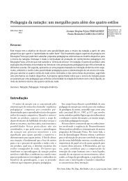
Hysteresis exists when the input–output relationship depends on whether the input<br />
force is increasing or decreasing, as in Figure 5.21(b). Hysteresis can be caused, for<br />
example, by the presence of deforming mechanical elements in the force transducers. It<br />
is expressed as the maximum difference between the output voltage for the same force,<br />
increasing and decreasing, divided by the full-scale output voltage. It should be 0.5% of<br />
full-scale deflection or less.<br />
Range<br />
The range of forces that can be measured must be adequate for the application and the<br />
range should be adjustable. If the range is <strong>to</strong>o small for the forces being measured, the<br />
output voltage will saturate (reach a constant value) as shown in Figure 5.21(c). Suitable<br />
maximum ranges for many sports biomechanics applications would be −10 <strong>to</strong> +10 kN<br />
for the two horizontal axes and −10 <strong>to</strong> +20 kN for the vertical axis.<br />
Sensitivity<br />
Sensitivity is the change in the recorded signal for a unit change in the force input,<br />
or the slope of the idealised linear voltage–force relationships of Figure 5.21. The<br />
sensitivity decreases with increasing range. Good sensitivity is essential as it is a limiting<br />
fac<strong>to</strong>r on the accuracy of the measurement. In most modern force plate systems, an<br />
analog-<strong>to</strong>-digital (A–D) converter is used and is usually the main limitation on the<br />
overall system resolution. An 8-bit A–D converter divides the input in<strong>to</strong> an output<br />
that can take one of 256 (2 8 ) discrete values. The resolution is then 100/255%,<br />
approximately 0.4%. A 12-bit A–D converter will improve the resolution <strong>to</strong> about<br />
0.025%. In a force plate system with adjustable range, it is essential <strong>to</strong> choose the range<br />
that just avoids saturation, so as <strong>to</strong> achieve optimum sensitivity. For example, consider<br />
that the maximum vertical force <strong>to</strong> be recorded is 4300 N, an 8-bit A–D converter is<br />
used, and a choice of ranges of 10 000 N, 5000 N and 2500 N is available. The best<br />
available range is 5000 N, and the force would be recorded approximately <strong>to</strong> the nearest<br />
20 N (5000/255). The percentage error in the maximum force is then only about<br />
0.5% (20 × 100/4300). A range of 10 000 N would double this error <strong>to</strong> about 1%. A<br />
range of 2500 N would cause saturation, and the maximum force recorded would be<br />
2500 N, an underestimate of over 40% (compare with Figure 5.21(c)).<br />
Crosstalk<br />
CAUSES OF MOVEMENT – FORCES AND TORQUES<br />
Force plates are normally used <strong>to</strong> measure force components in more than one direction.<br />
The possibility then exists of forces in one component direction affecting<br />
the forces recorded by the transducers used for the other components. The term<br />
crosstalk is used <strong>to</strong> express this interference between the recording channels for the<br />
various force components. Crosstalk must be small, preferably less than 3% of full-scale<br />
deflection.<br />
205