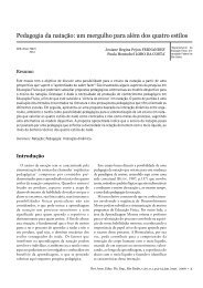
Introduction to Sports Biomechanics: Analysing Human Movement ...
Introduction to Sports Biomechanics: Analysing Human Movement ...
Introduction to Sports Biomechanics: Analysing Human Movement ...

Create successful ePaper yourself
Turn your PDF publications into a flip-book with our unique Google optimized e-Paper software.
Phase planes<br />
MORE ON MOVEMENT PATTERNS – THE GEOMETRY OF MOTION<br />
made of the loss of ‘time’ as a variable, although marking the data, or time, points as<br />
in Figure 3.16 adds some indication of how the angles change with time. We do, however,<br />
lose access <strong>to</strong> time-series shape patterns, that is slope = velocity; curvature =<br />
acceleration; such relationships do not apply <strong>to</strong> angle–angle diagrams.<br />
Perhaps the main criticism of angle–angle diagrams is that they do not show coordination<br />
changes very clearly without painstaking analysis of the patterns, as for the<br />
hip–knee coupling above. Only the ankle–knee coupling of the three joint couplings<br />
that we compared between walking and running was qualitatively different <strong>to</strong>pologically<br />
between the two modes of gait. Phase planes, a <strong>to</strong>tally different approach,<br />
are based on the notion that any system, such as a body segment, can be graphed as<br />
diagrams of two variables; for the phase planes used in human movement analysis, these<br />
variables are usually joint angle and angular velocity. As it turns out, although the<br />
relevance of a phase-plane for a single joint <strong>to</strong> coordination between joints may seem<br />
hard <strong>to</strong> fathom, phase planes turn out <strong>to</strong> be pivotal for our understanding of movement<br />
coordination, as will be evident later in this section.<br />
Example phase planes, for the hip (Figure 3.17(a)) and the knee (Figure 3.17(b))<br />
joints in a running stride, are shown in Figure 3.17. Its description – although not its<br />
analysis – is ‘child’s play’ compared <strong>to</strong> both angle–time series and angle–angle diagrams.<br />
As we define flexion as a decrease in joint angle and extension as an increase, then flexion<br />
must be from left <strong>to</strong> right and extension from right <strong>to</strong> left in Figure 3.17. Similarly, as<br />
we saw in the previous section on time series, a flexion velocity is negative and an<br />
extension velocity is positive; so, flexion must be below the horizontal (zero) line in<br />
Figure 3.17 and extension above it. And that is about that; the diagrams of Figure 3.17<br />
must progress clockwise. Why? Well let’s assume the opposite – they proceed anticlockwise.<br />
In this case, in the <strong>to</strong>p half of Figure 3.17(a) the joint would be flexing –<br />
from right <strong>to</strong> left – while the angular velocity was positive, indicating extension. We<br />
have proved a contradiction; therefore, our phase planes must progress clockwise with<br />
time.<br />
The value of phase planes starts <strong>to</strong> become evident when we define the so-called<br />
‘phase angle’ as shown for ‘real data’ in Figure 3.18. We have changed the graph so<br />
that it is ‘centred’ on its mean value, for reasons that need not concern us in this book.<br />
If we now subtract the phase angle – defined anticlockwise from the right horizontal –<br />
for one joint from that for a second joint at the same instant, we define a variable<br />
known as relative phase. Here, we subtract the knee phase angle from that for the<br />
hip, rp = pah – pak. We can do this for every time instant in the cycle <strong>to</strong> arrive at<br />
values of this relative phase as a function of time, which is known as ‘continuous relative<br />
phase’.<br />
A graph of continuous relative phase as a function of time is shown in Figure 3.19.<br />
Continuous relative phase is simply another coordination ‘pattern’, although more<br />
difficult <strong>to</strong> interpret than angle–angle diagrams. In Figure 3.19, for example, we see that<br />
103