Chain Drive KSM 400 (Instruction).pdf - ferralux.ro
Chain Drive KSM 400 (Instruction).pdf - ferralux.ro
Chain Drive KSM 400 (Instruction).pdf - ferralux.ro
- No tags were found...

You also want an ePaper? Increase the reach of your titles
YUMPU automatically turns print PDFs into web optimized ePapers that Google loves.
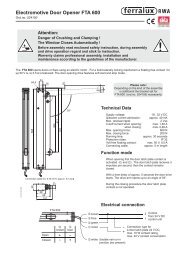
<st<strong>ro</strong>ng>Chain</st<strong>ro</strong>ng> <st<strong>ro</strong>ng>Drive</st<strong>ro</strong>ng> <st<strong>ro</strong>ng>KSM</st<strong>ro</strong>ng> <st<strong>ro</strong>ng>400</st<strong>ro</strong>ng>for natural ventilationDelivery includes:Ventilation drive <st<strong>ro</strong>ng>KSM</st<strong>ro</strong>ng> <st<strong>ro</strong>ng>400</st<strong>ro</strong>ng>Self sticking warning signDrilling measureMounting brackets24 V DC, app<strong>ro</strong>x. 2,0 A (ord.no. 524014)230 V AC, app<strong>ro</strong>x. 0,3 A (ord.no. 497304)Upper edge of drive11,65105,5288105,5M 646821 Bracket to mount drive at window 2 Casement bracket 3 Brace bracket4 Cap of mounting rail 5 Mounting rail 6 Cap7 Screw to connect mounting rail with cap 8 Locknut for eye bolt 9 Short eye bolt10 End of chain 11 Gudgeon 12 Safety screw for brace (1)13 Adjusting screw for st<strong>ro</strong>ke adjustmentAssembly (correct p<strong>ro</strong>ceeding)1. Select the app<strong>ro</strong>piate mounting method (see page 2 - 3)2. Brackets for mounting method 1 and 2 are included.3. Fix mounting rail and casement bracket according to theinstructions. (Frame height for mounting method 1 & 2 =min. 800 mm, for mounting method 3 - 5 = min. 500 mm).4. Fix the drive at the mounting rail.5. Fasten the end of chain at the casement bracket.6. Note: At overload disconnection possible (chain notreaching the end position) mind danger of gearing damage.The correct p<strong>ro</strong>ceeding for optimal adjustment of the endpositions is:<st<strong>ro</strong>ng>Drive</st<strong>ro</strong>ng> the chain in and close the casement. Now adjustthe eye bolt (9) for a easy thread of gudgeon (11) into thecasement bracket (1 or 2).After that secure the safety screw (12) with the locknut (8).7. The st<strong>ro</strong>ke can be adjusted with the adjusting screw (13).8. Pay attention to the drive run. The chain may not affect thecasement during the drive run. Otherwise the chain jams.Danger of gearing damage ! No warranty claims !No correct assembly!Caution !The chain may not affect the casementduring the drive run !Danger of gearing demage !No warrenty claims !Attention:Danger of Crushing and Clamping !The Window Closes Automatically !Before assembly read enclosed safety instruction, during assemblyand drive operation regard and stick to instruction.Warrenty claims p<strong>ro</strong>fessional assembly, installation andmaintenance according to the guidelines of the manufacturer.!1
<st<strong>ro</strong>ng>Chain</st<strong>ro</strong>ng> <st<strong>ro</strong>ng>Drive</st<strong>ro</strong>ng> <st<strong>ro</strong>ng>KSM</st<strong>ro</strong>ng> <st<strong>ro</strong>ng>400</st<strong>ro</strong>ng>Mounting examples (w/o options)Mounting method 1 - For pivot-hung, inward opening window (with Z-bracket)Frame(e.g. Schüco)Space requirements:min. 50 mm95.5105<st<strong>ro</strong>ng>KSM</st<strong>ro</strong>ng> <st<strong>ro</strong>ng>400</st<strong>ro</strong>ng>2 drillings forriveting nut M598 112Frame351332CasementCentre2 drillings forriveting nut M4min. 800Safety armOpening directionmin. 800285<st<strong>ro</strong>ng>KSM</st<strong>ro</strong>ng> <st<strong>ro</strong>ng>400</st<strong>ro</strong>ng>Connection cableCaution:Secure pivot-hung window with tiltingsafety arm !Don’t limit the adjusted st<strong>ro</strong>ke !max. 1500RA 1148-00.00.002Rotation point of casementMounting method 2 - For pivot-hung,inward opening window, with casement fixed driveView ZFrame(e.g. Schüco)105<st<strong>ro</strong>ng>KSM</st<strong>ro</strong>ng> <st<strong>ro</strong>ng>400</st<strong>ro</strong>ng>Space requirements:min. 26 mmmin. 800Safety armOpening direction2 drillings forriveting nut M52 drillings forriveting nut M4Casement21.5Frame1898 112Centre12<st<strong>ro</strong>ng>KSM</st<strong>ro</strong>ng> <st<strong>ro</strong>ng>400</st<strong>ro</strong>ng>285Caution:Secure pivot-hung window with tiltingsafety arm !Don’t limit the adjusted st<strong>ro</strong>ke !min. 800Flexiblec<strong>ro</strong>ssingof cableRotation point of casement2max. 1500RA 1148-00.00.002
<st<strong>ro</strong>ng>Chain</st<strong>ro</strong>ng> <st<strong>ro</strong>ng>Drive</st<strong>ro</strong>ng> <st<strong>ro</strong>ng>KSM</st<strong>ro</strong>ng> <st<strong>ro</strong>ng>400</st<strong>ro</strong>ng>Mounting exemples (with options)Mounting method 3 - For pivot-hung, inward opening drive mounted with pivoting bracket (ord.no. 524035)"A"2 drillings forriveting nut M4432124,57,5 22Frame"C""B"21X = 57 for mounting drilling "A”X = 36 for mounting drilling "B"X = 15 for mounting drilling "C"X198Casement Centre14 115 1294 drillings for riveting nut M614Pivoting bracketord.no. 524035Extended eye boltord.no. 524040Caution:Frame height: min 500 mmSecure frame withtilting safety arm90Pivoting bracket left215,2211935Pivoting bracket right10,2651432,5Extended eye bolt for mounting space >= 10 mm(e.g. wooden windows) ord.no. 5240403,484M 6335320Mounting method 4 - For outward opening drive, mounted at <strong>ro</strong>of-light,with pivoting bracket set (ord.no. 524038)140,524,5Centre of casementPivoting bracket set(2 pieces)ord.no. 5240384,5Æ 10,22,5 5,24238(leftexecution)1532,51235724427429520,5Opening direction329966LA 1076-51.00.002Mounting method 5 - <st<strong>ro</strong>ng>Drive</st<strong>ro</strong>ng> mounting at reveal- opening direction outwardsBracket set for reveal mounting (2 pieces) ord.no. 524034520493
<st<strong>ro</strong>ng>Chain</st<strong>ro</strong>ng> <st<strong>ro</strong>ng>Drive</st<strong>ro</strong>ng> <st<strong>ro</strong>ng>KSM</st<strong>ro</strong>ng> <st<strong>ro</strong>ng>400</st<strong>ro</strong>ng>Electrical connection of 24 V DC version24 V DCJunction box<st<strong>ro</strong>ng>Drive</st<strong>ro</strong>ng> end line module 70 M10 k10 k1 2 3 4 5<st<strong>ro</strong>ng>KSM</st<strong>ro</strong>ng> <st<strong>ro</strong>ng>400</st<strong>ro</strong>ng>Please note:Use 3-wire lead forline monitoring.Connect the drive end linemodule 70 M only to the lastin line junction box.<st<strong>ro</strong>ng>Drive</st<strong>ro</strong>ng> end line module 70 M(ord.no. 670051)connect it only in the lastto line junction boxblackredblackredflexible c<strong>ro</strong>ssing of connection cablewith linemonitoring1 2 3 4 5 6 7 8EMB 7000(terminal X4-Xn)orEMB 7100orEMB 7200Electrical connection of 230 V AC versionw/o linemonitoring1 2 3 4If the drive operates in the w<strong>ro</strong>ng direction interchangethe leads of connection cable.Check the colour of leads on one’s own responsibility.max. 1500 mm230 V ACL1Please note:Check the colour of CLOSE / OPENleads on one’s own responsibility.Nb<strong>ro</strong>wn - CLOSEblack - OPENblue or grey230 V AC<st<strong>ro</strong>ng>KSM</st<strong>ro</strong>ng> <st<strong>ro</strong>ng>400</st<strong>ro</strong>ng>min. 800 mmflexible c<strong>ro</strong>ssing of connection cableTechnical Data:• With end switches for OPEN and CLOSE• P<strong>ro</strong>tection class: IP 55• Connection cable: app<strong>ro</strong>x. 3,0 m• For pivot-hung, top-hung and turning sashand for <strong>ro</strong>of-light• With douple link chain made of stainless steel• Acustical warning in case of disconnection(chain not reaching the end position)Trusting / pulling force: max. 250 N / 300 NSt<strong>ro</strong>ke adjustable to 100-150-200-250-300-350-<st<strong>ro</strong>ng>400</st<strong>ro</strong>ng> mmLifting speed24 V DC version: app<strong>ro</strong>x. 18,0 mm/s (w/o load)230 V AC version: app<strong>ro</strong>x. 28,0 mm/s (w/o load)Nominal voltage:24 V DC or 230 V ACCurrent consumption:24 V DC version: app<strong>ro</strong>x. 2,0 A230 V AC version: app<strong>ro</strong>x. 0,3 AResidual ripple (at 24 V): max. 2 Vppaumüller aumatic gmbhSteinerne Furt 58a • 86167 AugsburgPhone: +49-821-270 93-0 • Fax: +49-821-70 98 42E-Mail: info@<st<strong>ro</strong>ng>ferralux</st<strong>ro</strong>ng>.de • Internet: www.<st<strong>ro</strong>ng>ferralux</st<strong>ro</strong>ng>.bizaumüller U.K. Ltd.6a Avon Gorge Ind. Estate • Portview Road • Bristol BS11 9LQPhone: +44-117-9820440 • Fax: +44-117-9820850 • e-mail: uk@<st<strong>ro</strong>ng>ferralux</st<strong>ro</strong>ng>.de201-1-0-1-1.2 MS(AK) 08.05Duty cycle: 20 %Suitable for parallel switchingAmbient temperature range: -5° C up to +50° CDimensions (W x H x D): 82 x 288 x 46 mmColour: RAL 9006(white aluminium like E6 / EV1)Technical modifications w/o advance notice reserved. We will not be held liable for printing / typing er<strong>ro</strong>rs.4201-1-0-1-8
Safety <st<strong>ro</strong>ng>Instruction</st<strong>ro</strong>ng>s for <st<strong>ro</strong>ng>Drive</st<strong>ro</strong>ng>sRead before assembly and keep the safety instructions over the life-span of drive!Danger of Crushing and Clamping !The Window Closes Automatically !When closing and opening the drive stops by the integratedor external overload disconnection (depending on the type ofdrive). For corresponding pressing force please refer thetechnical data.Caution - Accelerator can seriously injure fingers andlimbs. During assembly and operation, do not interfere intothe window gap and the travelling chain or spindle !Potential chrushing and cutting points between the casementand the frame, dome lights and support frame must be securedup to a height of 2,50 mtr. by safety measures, which immediatelystop in case of interference and therefore prevent injury.This does not apply to assembly in commercial and industrialenvi<strong>ro</strong>nment with exclusive entrance and use by instructedpersons.Assembly instructionfor p<strong>ro</strong>fessional assembly, installation and maintenance bytrained, qualified and sensible electricians and skilled fitterswith knowledge of electrical and mechanical drive assembly.Read and consider all informations in these assembly instructionand retain it for future use (maintenance).A reliable operation and an avoidance of damage and dangersis only guaranteed when the equipment is assembled carefullyand the setting are carried out according to these instruction.All measures are to be checked and adapted if necessary onone´s own authority.Please pay attention to connection assignment, the permissibleon drive voltage (see type indification plate), the minmum andmaximum power ratings (see technical data) and keep theassembly and installation notes exactly. Connect never 24 Vdrives to 230 V ! Mortal danger !Spare parts, attachements and cont<strong>ro</strong>lsThe drive operates reliably with cont<strong>ro</strong>ls of manufacturer. Onlyuse attachements of the manufacturer. No adhesion, warrantyand service obligations will be honored for third party p<strong>ro</strong>ducts.For spare parts or extension only use orginal spare parts.ApplicationsSuitable exclusive for automatic opening und closing of thewindows indicated in the assembly instruction. In case ofuncertainty contact the manufacturer or his representativefor further application informations.Always ensure that your system corresponds to the validregulations. In particular pay attention to opening range of thewindow, permissible fitting size, opening time and openingspeed, pressing force, temperature resistance of the drive andconnection cable, c<strong>ro</strong>sssection of the leads in relation to thecable length and power consumption. Required mounting partsare to be adapted to the window type and are to be complementedif necessary. P<strong>ro</strong>tect all aggregates f<strong>ro</strong>m dirt and moisture,exept drive is operatable within damp area (see technical data).Application of pivot-hung windowA chain drive requires a tilting safety arm. It prevents damageand danger for persons. Please note: The safety arm must beco-ordinated with the st<strong>ro</strong>ke length of the drive (see technicaldata). That means, the opening width of safety arm must belarger then the st<strong>ro</strong>ke length. Otherwise the safety arm willrestrict the drive’s range.Symbols for Safety <st<strong>ro</strong>ng>Instruction</st<strong>ro</strong>ng>s:!Attention !Danger for person byelectric currentAttention !Danger of crushing and clampingby drive operation(sticker is attached to the drive)Caution !Danger of the damageof drive and / or windowRouting of cable and electrical connectionsare only to be done by a qualified electrical company. In termsof installation stick to all significant guide lines (e.g. DIN VDE forGermany). If possible, agree on cable types with the local app<strong>ro</strong>valauthorities and fire p<strong>ro</strong>tection authority. Please note particulary:Install all low-voltage cables (24 V DC) separatly f<strong>ro</strong>m the highvoltagecables. Flexible cables must not to be plastered in and freelysuspended cables must be p<strong>ro</strong>vided with tension relief. The cablesmust be installed in such a way that they cannot be sheared off,twisted or bent off during operation. Junction boxes and external drivecont<strong>ro</strong>ls must be accessible for maintenance work. Implement cabletype, cable length and c<strong>ro</strong>sssection in accordance with the technicaldata. In order for maintenance and repair all 230 V system componentsmust be able to be disconnected f<strong>ro</strong>m the power supply.Maintenance and exchange of system componentsAllways disconnect in all-pole case the power supply and - so faravailable - the back-up batteries before maintenance work or exchangeof system components (e.g. exchange of the drive).A durable drive operation presupposes regular maintenance by thespecialized and qualified company (is legally prescribed with smokeand heat venting systems). The operational avialability status is to beexamined regularly. With the maintenance:Free the equipment f<strong>ro</strong>m any contamination. Check fixing and lockingscrews. Test the opening and closing operation by trail run. The motorgearing is maintenance-free. Defective equipment must only berepaired in our works. Only original spare parts are to be used.A service contract is recommended for this purpose.After installationand any changes to the system check all functions by means of a trailrun. After completion the user have must been instructed into allimportant operating steps.Manufacturer’s declarationThe drive including its cont<strong>ro</strong>ller is manufactured und tested accordingto the Eu<strong>ro</strong>pean Regulations. A corresponding manufacturer’sdeclaration has been submitted. You may only operate the equipment,if a Declaration of Conformity exists for the entire system.Total life-spanConsider with automatic operation (natural climatic and ventilationcont<strong>ro</strong>l) the total life-span of 10.000 ventilation cycles.DisposalThe drive contains electrical parts and must be disposed accordingto the national legal regulations.aumuller aumatic gmbhSteinerne Furt 58a • 86167 AugsburgPhone: +49-821-270 93-0 • Fax: +49-821-70 98 42E-Mail: info@<st<strong>ro</strong>ng>ferralux</st<strong>ro</strong>ng>.de • Internet: www.<st<strong>ro</strong>ng>ferralux</st<strong>ro</strong>ng>.bizaumuller U.K. Ltd.6a Avon Gorge Ind. Estate • Portview Road • Bristol BS11 9LQPhone: +44-117-9820440 • Fax: +44-117-9820850• e-mail: uk@<st<strong>ro</strong>ng>ferralux</st<strong>ro</strong>ng>.de121-80-0-9-1.2 MS(AK) 07.05121-80-0-9-8