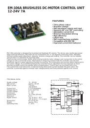
em-240 brushless dc-motor controller 12-24v 1.5a - Electromen
em-240 brushless dc-motor controller 12-24v 1.5a - Electromen
em-240 brushless dc-motor controller 12-24v 1.5a - Electromen
- No tags were found...

You also want an ePaper? Increase the reach of your titles
YUMPU automatically turns print PDFs into web optimized ePapers that Google loves.
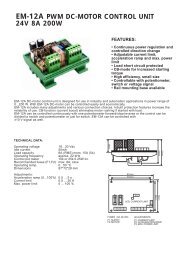
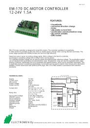
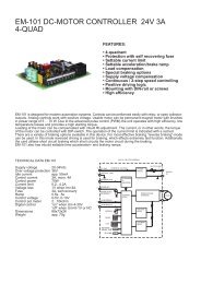
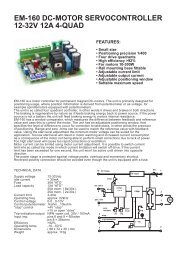
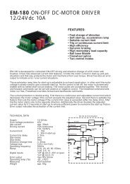
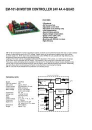
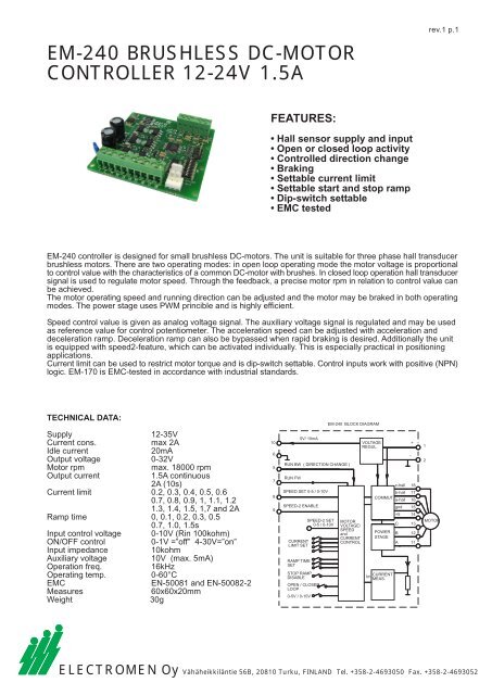
EM-<strong>240</strong> BRUSHLESS DC-MOTORCONTROLLER <strong>12</strong>-24V 1.5Arev.1 p.1FEATURES:• Hall sensor supply and input• Open or closed loop activity• Controlled direction change• Braking• Settable current limit• Settable start and stop ramp• Dip-switch settable• EMC testedEM-<strong>240</strong> <strong>controller</strong> is designed for small <strong>brushless</strong> DC-<strong>motor</strong>s. The unit is suitable for three phase hall transducer<strong>brushless</strong> <strong>motor</strong>s. There are two operating modes: in open loop operating mode the <strong>motor</strong> voltage is proportionalto control value with the characteristics of a common DC-<strong>motor</strong> with brushes. In closed loop operation hall transducersignal is used to regulate <strong>motor</strong> speed. Through the feedback, a precise <strong>motor</strong> rpm in relation to control value canbe achieved.The <strong>motor</strong> operating speed and running direction can be adjusted and the <strong>motor</strong> may be braked in both operatingmodes. The power stage uses PWM princible and is highly efficient.Speed control value is given as analog voltage signal. The auxiliary voltage signal is regulated and may be usedas reference value for control potentiometer. The acceleration speed can be adjusted with acceleration anddeceleration ramp. Deceleration ramp can also be bypassed when rapid braking is desired. Additionally the unitis equipped with speed2-feature, which can be activated individually. This is especially practical in positioningapplications.Current limit can be used to restrict <strong>motor</strong> torque and is dip-switch settable. Control inputs work with positive (NPN)logic. EM-170 is EMC-tested in accordance with industrial standards.TECHNICAL DATA:Supply <strong>12</strong>-35VCurrent cons.max 2AIdle current20mAOutput voltage 0-32VMotor rpmmax. 18000 rpmOutput current1.5A continuous2A (10s)Current limit 0.2, 0.3, 0.4, 0.5, 0.60.7, 0.8, 0.9, 1, 1.1, 1.21.3, 1.4, 1.5, 1,7 and 2ARamp time 0, 0.1, 0.2, 0.3, 0.50.7, 1.0, 1.5sInput control voltage 0-10V (Rin 100kohm)ON/OFF control0-1V =”off” 4-30V=”on”Input impedance10kohmAuxiliary voltage10V (max. 5mA)Operation freq.16kHzOperating t<strong>em</strong>p.0-60°CEMCEN-50081 and EN-50082-2Measures60x60x20mmWeight30g1065789RUN BW ( DIRECTION CHANGE )RUN FW5V/ 10mASPEED SET 0-5 / 0-10VSPEED-2 ENABLECURRENTLIMIT SETRAMP TIMESETSTOP RAMPDISABLEOPEN / CLOSEDLOOP0-5V / 0-10VSPEED-2 SET0-5 / 0-10VEM-<strong>240</strong> BLOCK DIAGRAMMOTORVOLTAGE/SPEEDandCURRENTCONTROLVOLTAGEREGUL.CURRENTImMEAS.c-hall 18b-hallCOMMUT.a-hallPOWERSTAGEgnd+5CBA+-1716151413<strong>12</strong>11<strong>12</strong>MOTORELECTROMEN Oy Vähäheikkiläntie 56B, 20810 Turku, FINLAND Tel. +358-2-4693050 Fax. +358-2-4693052
ev.1 p.2EM-<strong>240</strong> OPERATING INSTRUCTIONSSupply filtered <strong>12</strong>-35VDC withripple < 20% with full loadd.CAUTION ! reverse polarity can damage the unitCAUTION ! no internal fuseSETTINGS AND CONNECTING UNITHEIGHT 20mm5V ( 10mA )SPEED-2 ENABLESPEED-1FORWARD0V GNDREVERSE(DIRECTION)Switch off power before connecting <strong>motor</strong> andpower supply to EM-<strong>240</strong>. Prepare the controlcircuit. Set current limit and ramp timeaccording to application.30mm3.2mm60mmIn open loop mode <strong>motor</strong> rpm will drop whenloaded (in relation to control voltage),whereas in closed loop mode the <strong>motor</strong> rpm willbe constant (in relation to control voltage)unless the current limit is not exceeded. Thecontrol value relation to <strong>motor</strong> output voltageis illustrated in the chart below. Speed-2control value is given via molex-connector,the scaling is same as in speed-1 input. Ifspeed-2 feature is not required, thispotentiometer can simply be left out.Recommended speed control potentiometer valueis 2..50kohm for both speed-1 and speed-2.Control inputs can be used with switches, analogvoltage or NPN outputs of a logic. A voltagesignal greater than 4V is logic 1, maximum inputvoltage 30V. Forward input will start up the <strong>motor</strong>in forward direction. Reverse input will start upthe <strong>motor</strong> in reverse direction. When <strong>motor</strong> isalready running forward, direction will change.Speed-2 will set the running speed according toinput signal in molex connector. Notice:Speed-2 input will start up the <strong>motor</strong> in forwarddirection even if no other inputs are activated.Control voltage and speed set value are inreference with 0V gnd potential (pin6).60mm3mm+24Vcurrent limit / Adip-switches 1-42 1.7 1.5 1.40V1.3AEM-<strong>240</strong>BC+5hall 0V56mmA-hallB-hallBRUSHLESS DC1.2 1.1 1 0.9 0.8C-hallmolex-connector0 n2 5VSPEED20.7 0.6 0.5 0.4 0.30.2<strong>motor</strong> voltage / rpm in proportion to control valueramp time / sdip-switches 5-7closed loop controlopen loop control1.5 1 0.7 0.50.30.2 0.1 0rpmUm/Vsetting0-5Vsetting0-10V1800015000<strong>12</strong>0009000600030003025201510500 246 8 10 <strong>12</strong>control value / V"on" = deceleration on"off" = deceleration off= brake ondip-switch 8on = closed loopoff= open loopdip-switch 9on = 0-10Voff= 0-5Vdip-switch 10, control voltageCONTROL SET VOLTAGETAAKSEGND 0VETEENNOP-2REVERSEGND 0VFORWARDSPEED-2+10V567 8 910 567 8 910EXAMPLE 1Speed control with potentiometer.Speed-2 with external potentiometer.Control input with switches.EXAMPLE 2Speed control with voltage 0-5V or 0-10V.Speed-2 with external potentiometer.Control input with 4-30V<strong>dc</strong> voltage.