PICBASIC PLUS LITE Manual - Profe Saul
PICBASIC PLUS LITE Manual - Profe Saul
PICBASIC PLUS LITE Manual - Profe Saul
- No tags were found...

Create successful ePaper yourself
Turn your PDF publications into a flip-book with our unique Google optimized e-Paper software.
<strong>PICBASIC</strong> <strong>PLUS</strong><strong>LITE</strong>COMPILERVersion 1.0BASIC compiler for the 14-bit range of PIC micros.Near fully functional compiler, but limited to20 lines of code and two PICmicro’s.Namely, the 16F84 and the 16F877.
<strong>PICBASIC</strong> <strong>PLUS</strong> CompilerPlease Note.Although every precaution has been taken with the preparation of this manual to ensurethat any projects, designs or programs enclosed, operate in a correct and safe manner.The author and publisher assume no responsibility for errors or omissions. Neither isany liability assumed for the failure of any project, design or program, or any damagecaused to equipment that it may be connected to, or used in combination with.Copyright Crownhill Associates. All right reserved. No part of this publication may bereproduced, stored in a retrieval system, or distributed in any form or by any meanswithout the written permission of the publisher or author.The Microchip logo and name are registered trademarks of Microchip Technologies Inc.The EPIC tm programmer is a trade name of microEngineering Labs inc.<strong>PICBASIC</strong> <strong>PLUS</strong> is a trade name of Crownhill Associates.Published and distributed by Crownhill Associates LtdAuthor Les Johnson.First Edition August 2001.1Copyright Crownhill 2001
<strong>PICBASIC</strong> <strong>PLUS</strong> CompilerTable of Contents.1 - Introduction............................................................................................................................ 51.1. PIC Devices...................................................................................................................... 51.2. <strong>PICBASIC</strong> <strong>PLUS</strong> Discussion........................................................................................ 61.4. Contact Details................................................................................................................. 62 - Starting Out............................................................................................................................ 72.1. Installing the software ..................................................................................................... 72.3. Ready to start ?................................................................................................................ 82.4. Customising the editor..................................................................................................103 - Program Rules ....................................................................................................................113.1. Device specific issues...................................................................................................113.2. Identifiers.........................................................................................................................123.3. Line Labels .....................................................................................................................123.4. Variables .........................................................................................................................123.5. Aliases .............................................................................................................................133.6. Constants ........................................................................................................................133.7. Symbols...........................................................................................................................133.8. Numeric Representations.............................................................................................143.9. String Constants ............................................................................................................143.10. Ports and Other Registers .........................................................................................143.11. General Format............................................................................................................144 - Math operators....................................................................................................................154.1. Addition ‘+’.....................................................................................................................154.2. Subtraction ‘-‘................................................................................................................154.3. Multiply ‘*’.......................................................................................................................164.4. Multiply HIGH ‘**’..........................................................................................................164.5. Multiply MIDDLE ‘*/’.....................................................................................................164.6. Divide ‘/’..........................................................................................................................174.7. Modulus ‘//’....................................................................................................................174.8. Bitwise operators.............................................................................................................184.9. And ‘&’ ............................................................................................................................184.10. Or ‘|’ ..............................................................................................................................184.11. Xor ‘^’............................................................................................................................195 - <strong>PICBASIC</strong> <strong>PLUS</strong> Commands and Directives .............................................................205.1. ADIN ............................................................................................................................225.2. ASM – ENDASM and @ ..........................................................................................245.3. BRANCH ....................................................................................................................255.4. BRANCHL..................................................................................................................265.5. BUSIN .........................................................................................................................275.6. BUSOUT.....................................................................................................................305.7. CALL ...........................................................................................................................332Copyright Crownhill 2001
Table of Contents (continued…)<strong>PICBASIC</strong> <strong>PLUS</strong> Compiler5.8. CDATA........................................................................................................................345.9. CLS .............................................................................................................................365.10. CONFIG ...................................................................................................................375.11. COUNTER...............................................................................................................385.12. CREAD .....................................................................................................................395.13. CURSOR..................................................................................................................405.14. CWRITE ...................................................................................................................415.15. DATA........................................................................................................................425.16. DECLARE................................................................................................................43ADIN Declares.................................................................................................................43BUSIN, BUSOUT Declares..............................................................................................44LCD Declares...................................................................................................................44KEYPAD Declare. ............................................................................................................47RSIN-RSOUT Declares....................................................................................................47SHIN-SHOUT Declare......................................................................................................49CRYSTAL Frequency Declare..........................................................................................495.17. DELAYMS ................................................................................................................505.18. DELAYUS ................................................................................................................515.19. DEVICE ....................................................................................................................525.20. DIG............................................................................................................................535.21. DIM............................................................................................................................545.22. EDATA......................................................................................................................575.23. END...........................................................................................................................585.24. EREAD .....................................................................................................................595.25. EWRITE ...................................................................................................................605.26. FOR … NEXT … [STEP].......................................................................................615.27. GOSUB.....................................................................................................................625.28. GOTO .......................................................................................................................635.29. HIGH (or SET).........................................................................................................645.30. IF …THEN … ELSE … ENDIF.............................................................................655.31. INCLUDE.................................................................................................................675.32. INKEY.......................................................................................................................695.33. INPUT.......................................................................................................................705.34. [LET] .........................................................................................................................715.35. LCDREAD................................................................................................................725.36. LCDWRITE..............................................................................................................735.37. LOOKDOWN ...........................................................................................................745.38. LOOKDOWNL.........................................................................................................755.39. LOOKUP ..................................................................................................................765.40. LOOKUPL................................................................................................................775.41. LOW (or CLEAR) ....................................................................................................785.42. ON_INTERRUPT....................................................................................................795.43. OUTPUT...................................................................................................................855.44. ORG..........................................................................................................................865.45. PEEK ........................................................................................................................873Copyright Crownhill 2001
Table of Contents (continued…)<strong>PICBASIC</strong> <strong>PLUS</strong> Compiler5.46. PIXEL........................................................................................................................885.47. PLOT.........................................................................................................................895.48. POKE........................................................................................................................915.49. POT...........................................................................................................................925.50. PRINT.......................................................................................................................935.51. PULSIN...................................................................................................................1015.52. PULSOUT..............................................................................................................1025.53. PWM .......................................................................................................................1035.54. RANDOM ...............................................................................................................1045.55. RCIN .......................................................................................................................1055.56. READ ......................................................................................................................1085.57. REM........................................................................................................................1095.58. REPEAT … UNTIL ...............................................................................................1105.59. RESTORE..............................................................................................................1115.60. RETURN................................................................................................................1125.61. RSIN .......................................................................................................................1135.62. RSOUT...................................................................................................................1155.63. SERVO ...................................................................................................................1175.64. SET_OSCCAL.......................................................................................................1195.65. SHIN .......................................................................................................................1205.66. SHOUT...................................................................................................................1225.67. SNOOZE ................................................................................................................1245.68. SLEEP....................................................................................................................1255.69. SOUND...................................................................................................................1285.70. STOP ......................................................................................................................1295.71. SWAP .....................................................................................................................1305.72. SYMBOL ................................................................................................................1315.73. UNPLOT.................................................................................................................1325.74. WHILE … WEND..................................................................................................1336 - Incorporating Assembler into a BASIC program.....................................................134Assembler Labels ................................................................................................................134Assembler Literals...............................................................................................................135Assembler Variables...........................................................................................................136Special instruction mnemonics..........................................................................................137Memory Manipulation.........................................................................................................1387 - The on-board Programmer............................................................................................1417.1. Using the on-board Programmer..............................................................................1414Copyright Crownhill 2001
<strong>PICBASIC</strong> <strong>PLUS</strong> Compiler1 - IntroductionThe <strong>PICBASIC</strong> <strong>PLUS</strong> compiler was written with simplicity and flexibility in mind. UsingBASIC, which is almost certainly the easiest programming language around, you cannow produce extremely powerful applications for your PIC without having to learn therelative complexity of assembler. Having said this, we have included various ‘enhancements’for extra versatility and ease of use in the event that assembler is required.<strong>PICBASIC</strong> <strong>PLUS</strong> provides a seamless development environment, found with no otherPIC BASIC compiler, With <strong>PICBASIC</strong> <strong>PLUS</strong> , you can write, debug and compile yourcode within the same Windows environment, and by using a compatible programmer,just one key press allows you to program and verify the resulting code in the PIC of yourchoice!It should be noted that <strong>PICBASIC</strong> <strong>PLUS</strong> is NOT code compatible with the popular Parallax<strong>PICBASIC</strong>, which is a proprietary language, specific to their BASIC Stamp Parts.1.1. PIC DevicesThe devices supported by this software are the most commonly used and the compilertakes advantage of their various features e.g. The A/D converter in the 16F87x series,the data memory eeprom area in the 16C84 and 16F84. This manual is not intended togive you details about PIC devices Therefore for further information, visit the Microchipwebsite at www.microchip.com, and download the multitude of datasheets available.Because of the limited architecture of the 12-bit devices, the compiler is only compatiblewith the 14-bit core types. This isn’t such a limitation, as the 16C55x range of devicesmay be used instead of the original 16C5x devices. If an 8-pin device is required, theincredibly flexible 12C67x range may be used.5Copyright Crownhill 2001
<strong>PICBASIC</strong> <strong>PLUS</strong> Compiler1.2. <strong>PICBASIC</strong> <strong>PLUS</strong> DiscussionFor your convenience we have set up a web site www.letbasic.com, where there is asection for users of <strong>PICBASIC</strong> to discuss the compiler, and provide self help with programswritten for <strong>PICBASIC</strong>, or download sample programs. The web site is well wortha visit now and then either to learn a bit about how other peoples code works or to requesthelp should you encounter any problems with programs that you have written.To become a member of the discussion list, send an email to: -In the message body enter: -majordomo@qunos.netsubscribe LETBASIC-LThis will then reply with a message to verify your email address and ask you to reply.Once this is done, messages may be sent to: -letbasic-l@qunos.net1.4. Contact DetailsShould you need to get in touch with us for any reason our details are as follows: -Postal:Crownhill Associates Limited32 Broad StreetEly, CambridgeshireCB4 4AHTelephone: UK: 01353 666709Int: +44 1353 666709Fax: UK: 01353 666710Int: +44 1353 666710Email:Web Site:Sales@crownhill.co.ukhttp://www.crownhill.co.ukhttp://www/letbasic.com6Copyright Crownhill 2001
<strong>PICBASIC</strong> <strong>PLUS</strong> Compiler2 - Starting Out2.1. Installing the softwareUsing Windows explorer, change to your CD and locate the program called setup orsetup.exe this is the main install application. Double-click this and follow the on-screenprompts.Note, the software is now fully installed on your hard drive so there is no need to put theCD in when you want to run it.7Copyright Crownhill 2001
<strong>PICBASIC</strong> <strong>PLUS</strong> Compiler2.3. Ready to start ?Once the compiler is run you will be presented with an editor. This allows BASIC codeto be written, compiled, then programmed using one of many programmers. The editorimplements syntax highlighting for ease of use. All keywords, numbers, comments etchave a different colour representing them.The editor window above, shows a simple program for flashing an LED.The program is compiled by clicking on the Compile button, or right clicking themouse and choosing Compile. The program will then be compiled and assembled, andif there are no errors in the code, the Program button will be enabled. Any errors will bedisplayed on the bottom window, along with the offending line or lines.As an example of your first piece of code, enter the following program: -Again:DEVICE 16F84DECLARE XTAL 4SYMBOL LED = PORTB.0HIGH LEDDELAYMS 500LOW LEDDELAYMS 500GOTO AgainThis will flash an LED connected to bit-0 of PORTB.8Copyright Crownhill 2001
<strong>PICBASIC</strong> <strong>PLUS</strong> CompilerOnce the compile button is pressed, the following text should be displayed in the bottomwindow: -<strong>PICBASIC</strong> COMPILED OK. 60 Words used from a possible 102426 Variables used in the 16F84 from a possible 68The text is pretty much self explanatory in that it informs you that 60 words are used inthe 16F84 device, which has 1024 (1K) of available program memory. The same is truefor the variables used. The word ‘variable’ is used to indicate RAM memory, therefore ifa WORD size variable is used in the program, it will require two RAM locations. Eventhough the flashing LED program didn’t declare any variables, the compiler always usesa minimum of 26 RAM locations, these are it’s system variables.To view the assembler code produced, click on the View buttonappear displaying the assembled source code.A new window willThe code may now be programmed into the PIC by clicking the program buttonsection seven for details of the choices of programmer., see9Copyright Crownhill 2001
<strong>PICBASIC</strong> <strong>PLUS</strong> Compiler2.4. Customising the editor.The editor itself may be customised to a certain degree by choosing File->Editor Options.You will be presented with an options box that allows the syntax colours to bealtered along with how the editor handles tabs etc: -All the new settings are remembered by the compiler, so there’s no need to alter themevery time the editor is opened.10Copyright Crownhill 2001
<strong>PICBASIC</strong> <strong>PLUS</strong> Compiler3 - Program RulesAs with any language, there are rules you must follow when producing a program and<strong>PICBASIC</strong> <strong>PLUS</strong> is no exception. These are laid out in this section.3.1. Device specific issues.Before venturing into your latest project, always read the datasheet for the specific devicebeing used. Because some devices have features that may interfere with expectedpin operations. The PIC16C62x and the 16F62x devices are examples of this. ThesePICmicros have analogue comparators on PORTA. When these chips first power up,PORTA is set to analogue mode. This makes the pin functions on PORTA work in astrange manner. To change the pins to digital, simply add the following line near thefront of your BASIC program, or before any of the pins are accessed: -CMCON = 7Any PICmicro with analogue inputs, such as the PIC16C7xx, PIC16F87x andPIC12C67x series devices, will power up in analogue mode. If you intend to use themas digital types you must set the pins to digital by using the following line of code: -ADCON1 = 7Another example of potential problems is that bit-4 of PORTA (PortA.4) exhibits unusualbehaviour when used as an output. This is because the pin has an open drain outputrather than the usual bipolar stage as in the rest of the output pins. This means it canpull to ground when set to 0 (low), but it will simply float when set to a 1 (high), insteadof going high.To make this pin act as expected, add a pull-up resistor between the pin and 5 Volts. Atypical value resistor may be between 1K and 33K, depending on the device it is driving.If the pin is used as an input, it behaves the same as any other pin.Some PICmicros, such as the PIC16F87x range, allow low-voltage programming. Thisfunction takes over one of the PORTB (PortB.3) pins and can cause the device to acterratically if this pin is not pulled low. In normal use, It’s best to make sure that lowvoltageprogramming is disabled at the time the PICmicro is programmed. By default,the low voltage programming fuse is disabled, however, if the CONFIG directive is used,then it may inadvertently be omitted.All of the PICmicro pins are set to inputs on power-up. If you need a pin to be an output,set it to an output before you use it, or use a BASIC command that does it for you. Onceagain, always read the PICmicro data sheets to become familiar with the particular part.The name of the port pins on the PIC12C67x and 12CE67x devices is GPIO. The namefor the TRIS register is TRISIO: -GPIO.0 = 1TRISIO = %101010‘ Set GPIO.0 high‘ Manipulate ins and outs11Copyright Crownhill 2001
<strong>PICBASIC</strong> <strong>PLUS</strong> Compiler3.2. IdentifiersAn identifier is a technical term for a name. Identifiers are used in <strong>PICBASIC</strong> <strong>PLUS</strong> forline labels, variable names, and constant aliases. An identifier is any sequence of letters,digits, and underscores, although it must not start with a digit. Identifiers are notcase sensitive, therefore label, LABEL, and Label are all treated as equivalent. Andwhile labels might be any number of characters in length, only the first 32 are recognised.3.3. Line LabelsIn order to mark statements that the program may wish to reference with the GOTO,CALL, or GOSUB commands, <strong>PICBASIC</strong> <strong>PLUS</strong> uses line labels. Unlike many olderBASICs, <strong>PICBASIC</strong> <strong>PLUS</strong> doesn't allow or require line numbers and doesn't requirethat each line be labelled. Instead, any line may start with a line label, which is simply anidentifier followed by a colon ‘:’.Lab:PRINT “Hello World”GOTO Lab3.4. VariablesVariables are where temporary data is stored in a BASIC program. They are createdusing the DIM keyword. Because RAM space on PICmicros is somewhat limited in size,choosing the right size variable for a specific task is important. Variables may be bits,bytes or words. Space for each variable is automatically allocated in the micro controller’sRAM area. The format for creating a variable is as follows: -DIM Label as SizeLabel is any identifier, (excluding keywords). Size is BIT, BYTE or WORD. Some examplesof creating variables are: -DIM Dog as BYTE ‘ Create an 8-bit variable (0-255)DIM Cat as BIT ‘ Create a single bit variable (0-1)DIM Rat as WORD ‘ Create a 16-bit variable (0-65535)The number of variables available depends on the amount of RAM on a particular deviceand the size of the variables within the BASIC program. <strong>PICBASIC</strong> <strong>PLUS</strong> reservesapproximately 26 RAM locations for its own use. It may also create additional temporaryvariables for use when calculating complex equations.There are certain reserved words that cannot be used as variable names, these are thesystem variables used by the compiler.The following reserved words cannot be used as variable names: -PP0, PP0H, PP1, PP1H, PP2, PP2H, PP3, PP3H, PP4, PP4H, PP5, PP5H, PP6, PP6H,PP7, PP7H, GEN, GENH, GEN2, GEN2H, GEN3, GEN3H, GEN4, GEN4H, GPR, BPF.12Copyright Crownhill 2001
<strong>PICBASIC</strong> <strong>PLUS</strong> Compiler3.5. AliasesDIM can also be used to create an alias to a variable. This is very useful for accessingthe separate parts of a variable.DIM Fido as DogDIM Mouse as Rat.LOWBYTEDIM Tail as Rat.HIGHBYTEDIM Flea as Dog.0‘ Fido is another name for Dog‘ Mouse is the first byte (low byte) of word Rat‘ Tail is the second byte (high byte) of word Rat‘ Flea is bit-0 of Dog3.6. ConstantsNamed constants may be created in the same manner as variables. It can be more informativeto use a constant name instead of a constant number. Once a constant is declared,it cannot be changed later, hence the name ‘constant’.DIM Label as Constant expressionDIM Mouse as 1DIM Mice as Mouse * 4003.7. SymbolsSYMBOL provides yet another method for aliasing variables and constants. SYMBOLcannot be used to create a variable. Constants declared using SYMBOL do not use anyRAM within the PIC.SYMBOL Tiger = cat‘ Cat was previously created using DIMSYMBOL Mouse = 1 ‘ Same as DIM Mouse as 1SYMBOL Tigouse = Tiger + Mouse ‘ Add Tiger to Mouse to make TigouseIf a variable or register’s name is used in a constant expression then the variable’s orregister’s address will be substituted, not the value held in the variable or register: -SYMBOL CON = (PORTA + 1) ‘ CON will hold the value 6 (5+1)SYMBOL is also useful for aliasing Ports and Registers: -SYMBOL LED = PORTA.1SYMBOL T0IF = INTCON.2‘ LED now references bit-1 of PortA‘ T0IF now references bit-2 of INTCON registerThe equal sign between the Constant’s name and the alias value is optional: -SYMBOL LED PORTA.1‘ Same as SYMBOL LED=PORTA.113Copyright Crownhill 2001
<strong>PICBASIC</strong> <strong>PLUS</strong> Compiler3.8. Numeric Representations<strong>PICBASIC</strong> <strong>PLUS</strong> recognises four different number representations: -Binary is prefixed by %. i.e. %0101Hexadecimal is prefixed by $. i.e. $0ACharacter byte is surrounded by quotes. i.e. “a” represents a value of 97Decimal values need no prefix.3.9. String Constants<strong>PICBASIC</strong> <strong>PLUS</strong> doesn't provide conventional string handling capabilities, but stringscan be used with some commands. A string contains one or more characters and isdelimited by double quotes.PRINT "Hello World"‘ Output String ("H","e","l","l","o",” “,"W","o","r","l","d")Strings are usually treated as a list of individual character values, and are used by commandssuch as PRINT, RSOUT, BUSOUT, EWRITE etc.3.10. Ports and Other RegistersAll of the PICmicro registers, including the ports, can be accessed just like any otherbyte-sized variable. This means that they can be read from, written to or used in equationsdirectly:PORTA = %01010101Var = Wrd * PORTA‘ Write value to PORTA‘ Multiply variable WRD with the contents of PORTA3.11. General FormatThe compiler is not case sensitive, except when processing string constants such as“hello”.Multiple instructions and labels can be combined on the same line by separating themwith colons ‘:’.The examples below show the same program as separate lines and as a single-line...Multiple-line version: -TRISB = %00000000 ' Make all pins on PortB outputsFOR Var = 0 TO 100 ' Count from 0 to 100PORTB = Var' Make PortB = count (Var)NEXT' Continue counting until 100 is reachedSingle-line version: -TRISB = %00000000 : FOR Var = 0 TO 100 : PORTB = Var : NEXT14Copyright Crownhill 2001
<strong>PICBASIC</strong> <strong>PLUS</strong> Compiler4 - Math operatorsThe <strong>PICBASIC</strong> <strong>PLUS</strong> Compiler performs all math operations in full hierarchal order.Which means that there is precedence to the operators. For example, multiplies anddivides are performed before adds and subtracts. To ensure the operations are carriedout in the correct order use parenthesis to group the operations: -A = (( B – C ) * ( D + E )) / FAll math operations are unsigned and performed with 16-bit precision.The operators supported are: -+ Addition- Subtraction* Multiplication** Top 16 Bits of Multiplication*/ Middle 16 Bits of Multiplication/ Division// Remainder (Modulus)> Shift Right& Bitwise AND| Bitwise OR^ Bitwise XOR4.1. Addition ‘+’.The Addition operator (+) adds variables and/or constants, returning a 16-bit result.Works exactly as you would expect with unsigned integers from 0 to 65535. If the resultof addition is larger than 65535, the carry bit will be lost.DIM Value1 as WORDDIM Value2 as WORDValue1 = 1575Value2 = 976Value1 = Value1 + Value2PRINT @Value1' Add the numbers.' Display the result4.2. Subtraction ‘-‘.The Subtraction operator (-) subtracts variables and/or constants, returning a 16-bit result.Works exactly as you would expect with unsigned integers from 0 to 65535.DIM Value1 as WORDDIM Value2 as WORDValue1 = 1000Value2 = 999Value1 = Value1 - Value2PRINT @Value1' Subtract the numbers.' Display the result15Copyright Crownhill 2001
<strong>PICBASIC</strong> <strong>PLUS</strong> Compiler4.3. Multiply ‘*’.The Multiply operator (*) multiplies variables and/or constants, returning the low 16 bitsof the result. Works exactly as you would expect with unsigned integers from 0 to65535. If the result of multiplication is larger than 65535, the excess bits will be lost.DIM Value1 as WORDDIM Value2 as WORDValue1 = 1000Value2 = 19Value1 = Value1 * Value2PRINT @Value1' Multiply Value1 by Value2.' Display the result4.4. Multiply HIGH ‘**’.The Multiply High operator (**) multiplies variables and/or constants, returning the high16 bits of the result. When multiplying two 16-bit values, the result can be as large as 32bits. Since the largest variable supported by the compiler is 16-bits, the highest 16 bitsof a 32-bit multiplication result are normally lost. The ** (double-star) operand producesthese upper 16 bits.For example, suppose 65000 ($FDE8) is multiplied by itself. The result is4,225,000,000 or $FBD46240. The * (star, or normal multiplication) instruction wouldreturn the lower 16 bits, $6240. The ** instruction returns $FBD4.DIM Value1 as WORDDIM Value2 as WORDValue1 = $FDE8Value2 = Value1 ** Value1PRINT hex Value2' Multiply $FDE8 by itself' Return high 16 bits.4.5. Multiply MIDDLE ‘*/’.The Multiply Middle operator (*/) multiplies variables and/or constants, returning themiddle 16 bits of the 32-bit result. This has the effect of multiplying a value by a wholenumber and a fraction. The whole number is the upper byte of the multiplier (0 to 255whole units) and the fraction is the lower byte of the multiplier (0 to 255 units of 1/256each). The */ operand allows a workaround for the compiler’s integer-only math.Suppose we are required to multiply a value by 1.5. The whole number, and thereforethe upper byte of the multiplier, would be 1, and the lower byte (fractional part) would be128, since 128/256 = 0.5. It may be clearer to express the */ multiplier in HEX as $0180,since hex keeps the contents of the upper and lower bytes separate. Here's an example:DIM Value1 as WORDValue1 = 100Value1 = Value1 */ $0180 ' Multiply by 1.5 [1 + (128/256)]PRINT @Value1 ' Show result (150).16Copyright Crownhill 2001
<strong>PICBASIC</strong> <strong>PLUS</strong> CompilerTo calculate constants for use with the */ instruction, put the whole number portion in theupper byte, then use the following formula for the value of the lower byte: -INT(fraction * 256)For example, take Pi (3.14159). The upper byte would be $03 (the whole number), andthe lower would be INT(0.14159 * 256) = 36 ($24). So the constant Pi for use with */would be $0324. This isn’t a perfect match for Pi, but the error is only about 0.1%.4.6. Divide ‘/’.The Divide operator (/) divides variables and/or constants, returning a 16-bit result.Works exactly as you would expect with unsigned integers from 0 to 65535.DIM Value1 as WORDDIM Value2 as WORDValue1 = 1000Value2 = 5Value1 = Value1 / Value2 ' Divide the numbers.PRINT @Value1 ' Show the result (200).4.7. Modulus ‘//’.The Modulus operator (//) returns the remainder left after dividing one value by another.Some division problems don’t have a whole-number result; they return a whole numberand a fraction. For example, 1000/6 = 166.667. Integer math doesn’t allow the fractionalportion of the result, so 1000/6 = 166. However, 166 is an approximate answer, because166*6 = 996. The division operation left a remainder of 4. The // returns the remainder ofa given division operation. Numbers that divide evenly, such as 1000/5, produce a remainderof 0: -DIM Value1 as WORDDIM Value2 as WORDValue1 = 1000Value2 = 6Value1 = Value1 // Value2 ' Get remainder of Value1 / Value2.PRINT @Value1 ' Show the result (4).17Copyright Crownhill 2001
4.8. Bitwise operators.<strong>PICBASIC</strong> <strong>PLUS</strong> Compiler4.9. And ‘&’The And operator (&) returns the bitwise AND of two values. Each bit of the values issubject to the following logic: -0 AND 0 = 00 AND 1 = 01 AND 0 = 01 AND 1 = 1The result returned by & will contain 1s in only those bit positions in which both inputvalues contain 1s: -DIM Value1 as BYTEDIM Value2 as BYTEDIM Result as BYTEValue1 = %00001111Value2 = %10101101Result = Value1 & Value2PRINT bin Result ' Display AND result (%00001101)orPRINT bin ( %00001111 & %10101101 ) ' Display AND result (%00001101)4.10. Or ‘|’The OR operator (|) returns the bitwise OR of two values. Each bit of the values is subjectto the following logic: -0 OR 0 = 00 OR 1 = 11 OR 0 = 11 OR 1 = 1The result returned by | will contain 1s in any bit positions in which oneor the other (or both) input values contain 1s: -DIM Value1 as BYTEDIM Value2 as BYTEDIM Result as BYTEValue1 = %00001111Value2 = %10101001Result = Value1 | Value2PRINT bin Result ' Display OR result (%10101111)orPRINT bin ( %00001111 | %10101001 ) ' Display OR result (%10101111)18Copyright Crownhill 2001
<strong>PICBASIC</strong> <strong>PLUS</strong> Compiler4.11. Xor ‘^’The Xor operator (^) returns the bitwise XOR of two values. Each bit of the values issubject to the following logic: -0 XOR 0 = 00 XOR 1 = 11 XOR 0 = 11 XOR 1 = 0The result returned by ^ will contain 1s in any bit positions in which one or the other (butnot both) input values contain 1s: -DIM Value1 as BYTEDIM Value2 as BYTEDIM Result as BYTEValue1 = %00001111Value2 = %10101001Result = Value1 ^ Value2PRINT bin Result ' Display XOR result (%10100110)-- or --PRINT bin ( %00001111 ^ %10101001 ) ' Display XOR result (%10100110)19Copyright Crownhill 2001
<strong>PICBASIC</strong> <strong>PLUS</strong> Compiler5 - <strong>PICBASIC</strong> <strong>PLUS</strong> Commands and DirectivesADINASM-ENDASMBRANCHBRANCHLBUSINBUSOUTCALLCDATACLSCONFIGCOUNTERCREADCURSORCWRITEDATADECLAREDELAYMSDELAYUSDEVICEDIGDIMEDATAENDEREADEWRITEFOR…TO…NEXT…STEPGOSUB….RETURNGOTOHIGH (or SET)IF…THEN…ELSE…ENDIFINCLUDEINKEYINPUT[LET]LCDREADLCDWRITELOOKDOWNLOOKDOWNLLOOKUPLOOKUPLLOW (or CLEAR)ON_INTERRUPTOUTPUTORGPEEKRead on-chip analog to digital converter.Insert assembly language code section.Computed GOTO (equiv. to ON..GOTO).BRANCH out of page (long BRANCH).Read bytes from I 2 C device.Write bytes to I 2 C device.Call assembly language subroutine.Define initial contents in memory.Clear the LCD.Set or Reset programming fuse configurations.Count number of pulses on a pin.Read word from code memory.Position the cursor on the LCD.Write word to code memory.Define initial contents in memory.Adjust library routine parameters.Delay (1mSec resolution).Delay (1uSec resolution).Choose the type of PIC to compile with.Return the value of a decimal digit.Create a variable.Define initial contents of on-chip EEPROM.Stop execution.Read byte or word from on-chip EEPROM.Write byte to on-chip EEPROM.Repeatedly execute statements.Call BASIC subroutine at specified label.Continue execution at specified label.Make pin, port, or register high.Conditionally execute statements.Load a BASIC file into the source code.Scan a keypad.Make pin an input.Assign result of an expression to a variable.Read a single byte from a Graphic LCD.Write bytes to a Graphic LCD.Search constant table for value.Search constant / variable table for value.Fetch constant value from table.Fetch constant / variable value from table.Make pin, port, or register low.Execute a subroutine on a HARWARE interrupt.Make pin an output.Set Program Origin.Read byte from register.20Copyright Crownhill 2001
<strong>PICBASIC</strong> <strong>PLUS</strong> Compiler<strong>PICBASIC</strong> <strong>PLUS</strong> Commands and Directives (continued)PIXELPLOTPOKEPOTPRINTPULSINPULSOUTPWMRANDOMRCINREADREMREPEAT…UNTILRESTORERETURNRSINRSOUTSERVOSET_OSCCALSHINSHOUTSNOOZESLEEPSOUNDSTOPSWAPSYMBOLUNPLOTWHILE…WENDRead a single pixel from a Graphic LCD.Set a single pixel on a Graphic LCD.Write byte to register.Read potentiometer on specified pin.Display characters on LCD.Measure pulse width on a pin.Generate pulse to a pin.Output pulse width modulated pulse train to pin.Generate a pseudo-random number.Measure pulse width on a pin.Read byte or word from memory.Add a remark to the source code.Execute statements until condition is true.Adjust the position of data to READ.Continue at statement following last GOSUB.Asynchronous serial input from fixed pin and baud.Asynchronous serial output to fixed pin and baud.Control a servo motor.Calibrate the on-chip oscillator.Synchronous serial input.Synchronous serial output.Power down processor for short period of time.Power down processor for a period of time.Generate tone or white-noise on specified pin.Stop program execution.Exchange the values of two variables.Create an alias to a constant, port, pin, or registerClear a single pixel on a Graphic LCD.Execute statements while condition is true.21Copyright Crownhill 2001
<strong>PICBASIC</strong> <strong>PLUS</strong> Compiler5.1. ADINSyntax :Overview :Operators :Example :variable = ADIN channel numberRead the value from the on-board Analogue to Digital Converter.Variable is a user defined variable.Channel number can be a constant or a variable expression.‘Read the value from channel 0 of the ADC and place in variable Var.DECLARE ADIN_RES 10 ‘ 10-bit result requiredDECLARE ADIN_TAD FRC ‘ RC Osc chosenDECLARE ADIN_STIME 50 ‘ Allow 50us sample timeDIM Var as WORDTRISA = %00000001 ‘ Configure AN0 (PortA.0) as an inputADCON1=%10000000 ‘ Set analogue input on PortA.0Var=ADIN 0‘ Place the conversion into variable VARDeclares :There are three DECLARE directives for use with ADIN.These are: -DECLARE ADIN_RES 8 , 10 , or 12.Sets the number of bits in the result.If this DECLARE is not used, then the default is the resolution of thePIC type used. For example, the new 16F87X range will result in aresolution of 10-bits, while the standard PIC types will produce an 8-bit result. Using the above DECLARE allows an 8-bit result to be obtainedfrom the 10-bit PIC types, but NOT 10-bits from the 8-bit types.DECLARE ADIN_TAD 2_FOSC , 8_FOSC , 32_FOSC , or FRC.Sets the ADC’s clock source.All compatible PICs have four options for the clock source used by theADC. 2_FOSC, 8_FOSC, and 32_FOSC, are ratios of the externaloscillator, while FRC is the PIC’s internal RC oscillator. Instead of usingthe predefined names for the clock source, values from 0 to 3 maybe used. These reflect the settings of bits 0-1 in register ADCON0.Care must be used when issuing this DECLARE, as the wrong type ofclock source may result in poor resolution, or no conversion at all. If indoubt use FRC which will produce a slight reduction in resolution andconversion speed, but is guaranteed to work first time, every time.FRC is the default setting if the DECLARE is not issued in the BASIClisting.22Copyright Crownhill 2001
<strong>PICBASIC</strong> <strong>PLUS</strong> CompilerDECLARE ADIN_STIME 0 to 65535 microseconds (us).Allows the internal capacitors to fully charge before a sample is taken.This may be a value from 0 to 65535 microseconds (us).A value too small may result in a reduction of resolution. While toolarge a value will result in poor conversion speeds without any extraresolution being attained.A typical value for ADIN_STIME is 50 to 100. This allows adequatecharge time without loosing too much conversion speed. But experimentationwill produce the right value for your particular requirement.The default value if the DECLARE is not used in the BASIC listing is50.Notes :Before the ADIN command may be used, the appropriate TRIS registermust be manipulated to set the desired pin to an input. Also, theADCON1 register must be set according to which pin is required asan analogue input, and in some cases, to configure the format of theconversion’s result. See the numerous Microchip datasheets for moreinformation on these registers and how to set them up correctly for thespecific device used.If multiple conversions are being implemented, then a small delayshould be used after the ADIN command. This allows the ADC’s internalcapacitors to discharge fully: -Again: Var = ADIN 3 ‘ Place the conversion into variable VarDELAYUS 1 ‘ Wait for 1usGOTO Again ‘ Read the ADC foreverSee also :RCIN, POT23Copyright Crownhill 2001
5.2. ASM – ENDASM and @<strong>PICBASIC</strong> <strong>PLUS</strong> CompilerSyntax :ASMassembler mnemonicsENDASMor@ assembler mnemonicOverview :Incorporate in-line assembler in the BASIC code. The mnemonics arepassed directly to the assembler without the compiler interfering inany way. This allows a great deal of flexibility that cannot always beachieved using BASIC commands alone.The <strong>PICBASIC</strong> <strong>PLUS</strong> compiler caters for using assembler like noother BASIC compiler available. Because this is a rather detailed subject,section 6 has been specially written to answer some of yourquestions and illustrate how assembler mnemonics may be used withthe compiler.24Copyright Crownhill 2001
<strong>PICBASIC</strong> <strong>PLUS</strong> Compiler5.3. BRANCHSyntax : BRANCH Index, [Label1 {,...Labeln }]Overview :Operators :Cause the program to jump to different locations based on a variableindex. On a PIC device with only one page of memory.Index is a constant, variable, or expression, that specifies the addressto branch to.Label1,...Labeln are valid labels that specify where to branch to.Example : DEVICE 16F84DIM index as BYTEStart: index = 2 ‘assign index a value of 2‘jump to label 2 (Lab_2) because index = 2BRANCH index,[Lab_0, Lab_1, Lab_2]Lab_0: index = 2 ‘index now equals 2GOTO StartLab_1: index = 0 ‘index now equals 0GOTO StartLab_2: index = 1 ‘index now equals 1GOTO StartThe above example we first assign the index variable a value of 2,then we define our labels. Since the first position is considered 0 andthe variable index equals 2 the BRANCH command will cause theprogram to jump to the third label in the brackets [Lab2].Notes :BRANCH is similar to the ON x GOTO command found in other BA-SICs. It’s useful when you want to organise a structure such as: -IF Var = 0 THEN GOTO Lab_0IF Var = 1 THEN GOTO Lab_1IF Var = 2 THEN GOTO Lab_2' Var =0: go to label "Lab_0"' Var =1: go to label "Lab_1"' Var =2: go to label "Lab_2"You can use BRANCH to organize this into a single statement: -BRANCH Var, [Lab_0 , Lab_1, Lab_2]This works exactly the same as the above IF...THEN example. If thevalue is not in range (in this case if Var is greater than 2), BRANCHdoes nothing. The program continues with the next instruction..The BRANCH command is primarily for use with PIC devices thathave one page of memory (0-2047). If larger PIC’s are used and yoususpect that the branch label will be over a page boundary, use theBRANCHL command instead.See also :BRANCHL25Copyright Crownhill 2001
<strong>PICBASIC</strong> <strong>PLUS</strong> Compiler5.4. BRANCHLSyntax : BRANCHL Index, [Label1 {,...Labeln }]Overview :Operators :Cause the program to jump to different locations based on a variableindex. On a PIC device with more than one page of memory.Index is a constant, variable, or expression, that specifies the addressto branch to.Label1,...Labeln are valid labels that specify where to branch to.Example : DEVICE 16F877DIM index as BYTEStart: index = 2 ‘assigned index a value of 2‘jump to label 2 (Lab2) because index = 2BRANCHL index , [Lab0, Lab1, Lab2]Lab1: index = 2 ‘index now equals 2GOTO StartLab2: index = 0 ‘index now equals 0GOTO StartLab3: index = 1 ‘index now equals 1GOTO StartThe above example we first assign the index variable a value of 2,then we define our labels. Since the first position is considered 0 andthe variable index equals 2 the BRANCHL command will cause theprogram to jump to the third label in the brackets [Lab2].Notes :See also :The BRANCHL command is mainly for use with PIC devices thathave more than one page of memory (greater than 2048). It may alsobe used on any PIC device, but does produce code that is larger thanBRANCH.BRANCH26Copyright Crownhill 2001
<strong>PICBASIC</strong> <strong>PLUS</strong> Compiler5.5. BUSINSyntax : Variable = BUSIN Control , { Address }orBUSIN Control , { Address }, [ Variable {, Variable…} ]Overview :Operators :Receives a value from the I 2 C bus and places it into variable/s. By firstsending the control and optional address out of the clock pin (SCL),and data pin (SDA).Variable is a user defined variable or constant.Control may be a constant value or a BYTE sized variable expression.Address may be a constant value or a variable expression.The two variations of the BUSIN command may both be used in thesame BASIC program. The first type is useful for simply receiving asingle value from the bus. The second type may be used to receiveseveral values and designate each to a separate variable.The BUSIN command operates as an I 2 C master and may be used tointerface with any device that complies with the 2-wire I 2 C protocol.The most significant 7-bits of control byte contain the control code andthe slave address of the device being interfaced with. Bit-0 is the flagthat indicates whether a read or write command is being implemented.For example, if we were interfacing to an external eeprom such as the24C32, the control code would be %10100001 or $A1. The most significant4-bits (1010) are the eeprom’s unique slave address. Bits 2 to3 reflect the three address pins of the eeprom. And Bit-0 is set to signifythat we wish to read from the eeprom. Note that this bit is automaticallyset by the BUSIN command, regardless of its initial setting.Example :‘ Receive a byte from the I 2 C bus and place it into variable Var.DIM Var as BYTE‘ We’ll only read 8-bitsDIM Address as WORD ‘ 16-bit address requiredSYMBOL Control %10100001 ‘ Target an eepromAddress = 20 ‘ Read the value at address 20Var = BUSIN Control , Address ‘ Read the byte from the eepromorBUSIN Control , Address, [ Var ]‘ Read the byte from the eeprom27Copyright Crownhill 2001
<strong>PICBASIC</strong> <strong>PLUS</strong> CompilerAddress, is an optional parameter that may be an 8-bit or 16-bit value.If a variable is used in this position, the size of address is dictated bythe size of the variable used (BYTE or WORD). In the case of theprevious eeprom interfacing, the 24C32 eeprom requires a 16-bit address.While the smaller types require an 8-bit address. Make sureyou assign the right size address for the device interfaced with, or youmay not achieve the results you intended.The value received from the bus depends on the size of the variablesused. For example: -DIM Wrd as WORDWrd = BUSIN Control , Address‘ Declare a WORD size variableWill receive a 16-bit value from the bus. While: -DIM Var as BYTEVar = BUSIN Control , Address‘ Declare a BYTE size variableWill receive an 8-bit value from the bus.Using the second variation of the BUSIN command allows differingvariable assignments. For example: -DIM Var as BYTEDIM Wrd as WORDBUSIN Control , Address , [ Var , Wrd ]Will receive two values from the bus, the first being an 8-bit value dictatedby the size of variable VAR which has been declared as a byte.And a 16-bit value, this time dictated by the size of the variable WRDwhich has been declared as a word. Of course, BIT type variablesmay also be used, but in most cases these are not of any practicaluse as they still take up a byte within the eeprom.Declares :There are three DECLARE directives for use with BUSIN.These are: -DECLARE SDA_PIN PORT . PINDeclares the port and pin used for the data line (SDA). This may beany valid port on the PIC. If this declare is not issued in the BASICprogram, then the default Port and Pin is PortA.0DECLARE SCL_PIN PORT . PINDeclares the port and pin used for the clock line (SCL). This may beany valid port on the PIC. If this declare is not issued in the BASICprogram, then the default Port and Pin is PortA.128Copyright Crownhill 2001
<strong>PICBASIC</strong> <strong>PLUS</strong> CompilerThese declares, as is the case with all the DECLARES, may only beissued once in any single program, as they setup the I 2 C library codeat design time.You may imagine that it’s limiting having a fixed interface, but youmust remember that several different devices may be attached to asingle bus, each having a unique slave address. Which means thereis no need to use up more than two pins on the PIC.DECLARE SLOW_BUS ON - OFF or 1 - 0Slows the bus speed when using an oscillator higher than 4MHz.The standard speed for the I 2 C bus is 100KHz. Some devices use ahigher bus speed of 400KHz. If you use an 8MHz or higher oscillator,the bus speed may exceed the devices specs, which will result in intermittentreads, or in some cases, no reads at all. Therefore, use thisDECLARE if you are not sure of the device’s spec. The datasheet forthe device used will inform you of its bus speed.Notes :When the BUSIN command is used, the appropriate SDA and SCLPort and Pin are automatically setup for ins and outs.Because the I 2 C protocol calls for an open-collector interface, pull-upresistors are required on both the SDA and SCL lines. Values of 4.7Kto 10K Ohms will suffice.See also :BUSOUT for suitable circuit, DECLARE29Copyright Crownhill 2001
<strong>PICBASIC</strong> <strong>PLUS</strong> Compiler5.6. BUSOUTSyntax : BUSOUT Control , { Address } , [ Variable {, Variable…} ]Overview :Operators :Transmit a value to the I 2 C bus by first sending the control and optionaladdress out of the clock pin (SCL), and data pin (SDA).Variable is a user defined variable or constant.Control may be a constant value or a BYTE sized variable expression.Address may be a constant, variable, or expression.The BUSOUT command operates as an I 2 C master and may be usedto interface with any device that complies with the 2-wire I 2 C protocol.The most significant 7-bits of control byte contain the control code andthe slave address of the device being interfaced with. Bit-0 is the flagthat indicates whether a read or write command is being implemented.For example, if we were interfacing to an external eeprom such as the24C32, the control code would be %10100000 or $A0. The most significant4-bits (1010) are the eeprom’s unique slave address. Bits 2 to3 reflect the three address pins of the eeprom. And Bit-0 is clear tosignify that we wish to write to the eeprom. Note that this bit is automaticallycleared by the BUSOUT command, regardless of its initialvalue.Example :‘ Send a byte to the I 2 C bus.DIM Var as BYTE‘ We’ll only read 8-bitsDIM Address as WORD ‘ 16-bit address requiredSYMBOL Control %10100000 ‘ Target an eepromAddress = 20 ‘ Write to address 20Var = 200 ‘ The value place into address 20BUSOUT Control , Address , [ Var ] ‘ Send the byte to the eepromDELAYMS 5‘ Allow time for allocation of byteAddress, is an optional parameter that may be an 8-bit or 16-bit value.If a variable is used in this position, the size of address is dictated bythe size of the variable used (BYTE or WORD). In the case of theabove eeprom interfacing, the 24C32 eeprom requires a 16-bit address.While the smaller types require an 8-bit address. Make sureyou assign the right size address for the device interfaced with, or youmay not achieve the results you intended.30Copyright Crownhill 2001
<strong>PICBASIC</strong> <strong>PLUS</strong> CompilerThe value sent to the bus depends on the size of the variables used.For example: -DIM Wrd as WORD‘ Declare a WORD size variableBUSOUT Control , Address , [ Wrd ]Will send a 16-bit value to the bus. While: -DIM Var as BYTEBUSOUT Control , Address , [ Var ]‘ Declare a BYTE size variableWill send an 8-bit value to the bus.Using more than one variable within the brackets allows differing variablesizes to be sent. For example: -DIM Var as BYTEDIM Wrd as WORDBUSOUT Control , Address , [ Var , Wrd ]Will send two values to the bus, the first being an 8-bit value dictatedby the size of variable VAR which has been declared as a byte. And a16-bit value, this time dictated by the size of the variable WRD whichhas been declared as a word. Of course, BIT type variables may alsobe used, but in most cases these are not of any practical use as theystill take up a byte within the eeprom.A string of characters can also be transmitted, by enclosing them inquotes: -BUSOUT Control , Address , [ “Hello World” , Var , Wrd ]Declares :There are four DECLARE directives for use with BUSOUT.These are: -DECLARE SDA_PIN PORT . PINAssigns the port and pin used for the data line (SDA). This may beany valid port on the PIC. If this declare is not issued in the BASICprogram, then the default Port and Pin is PortA.0DECLARE SCL_PIN PORT . PINAssigns the port and pin used for the clock line (SCL). This may beany valid port on the PIC. If this declare is not issued in the BASICprogram, then the default Port and Pin is PortA.1These declares, as is the case with all the DECLARES, may only beissued once in any single program, as they setup the I 2 C library codeat design time.31Copyright Crownhill 2001
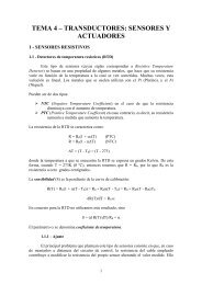
<strong>PICBASIC</strong> <strong>PLUS</strong> CompilerYou may imagine that it’s limiting having a fixed interface, but youmust remember that several different devices may be attached to asingle bus, each having a unique slave address. Which means thereis no need to use up more than two pins on the PIC.DECLARE SLOW_BUS ON - OFF or 1 - 0.Slows the bus speed when using an oscillator higher than 4MHz.The standard speed for the I 2 C bus is 100KHz. However, some devicesuse a higher bus speed of 400KHz. If you use an 8MHz orhigher oscillator, the bus speed may exceed the devices specs, whichwill result in intermittent writes, or in some cases, no writes at all.Therefore, use this DECLARE if you are not sure of the device’s spec.The datasheet for the device used will inform you of its bus speed.Notes :When the BUSOUT command is used, the appropriate SDA and SCLPort and Pin are automatically setup for ins and outs.Because the I 2 C protocol calls for an open-collector interface, pull-upresistors are required on both the SDA and SCL lines. Values from4.7KΩ to 10KΩ will usually suffice.See also :BUSIN+5 Volts0VC110uFC20.1uFR14.7k4MHzCrystalC322pF41615C422pF14VDDRB7MCLR RB6RB5RB4RB3OSC1 RB2RB1RB0PIC16F84RA4OSC2 RA3RA2RA1VSS RA051312111098763211817R2-R34.7k658VCC24C32SCLSDA VSS4WPA0A1A27123A typical use for the I 2 C commands is for interfacing with serialeeproms. The diagram shows the connections to the I 2 C bus of a24C32 serial eeprom.32Copyright Crownhill 2001
<strong>PICBASIC</strong> <strong>PLUS</strong> Compiler5.7. CALLSyntax :Overview :Operators :Example :CALL LabelExecute the assembly language subroutine named label.Label must be a valid label name.‘ Call an assembler routineCALL Asm_SubASMAsm_Sub{mnemonics}ReturnENDASMNotes :See also :The GOSUB command is usually used to execute a BASIC subroutine.However, if your subroutine happens to be written in assembler,the CALL command should be used. The main difference betweenGOSUB and CALL is that when CALL is used, the label’s existenceis not checked until assembly time. Using CALL, a label in an assemblylanguage section can be accessed that would otherwise be inaccessibleto GOSUB. This also means that any errors produced will beassembler types.GOSUB, GOTO33Copyright Crownhill 2001
<strong>PICBASIC</strong> <strong>PLUS</strong> Compiler5.8. CDATASyntax : CDATA { alphanumeric data }Overview :Operators :Place information directly into memory for access by CREAD andCWRITE.alphanumeric data can be any alphabetic character or string enclosedin quotes (“) or numeric data without quotes.Example : DEVICE 16F877 ‘ Use a 16F877 PICDIM Var as BYTEVar = CREAD 2000 ‘ Read the data from address 2000ORG 2000‘ Set the address of the CDATA commandCDATA 120 ‘ Place 120 at address 2000In the above example, the data is located at address 2000 within thePIC, then it’s read using the CREAD command.Notes :CDATA is only available on the newer PIC types that have selfmodifyingfeatures, such as the 16F87x range.In order for the CREAD and CWRITE commands to locate the data inmemory, CDATA commands should be preceded by an ORG directive.ORG 4000 ‘ Move the address pointer to 4000CDATA “Hello World” , 16200 , 253 ‘ Place the data at address 4000The above example, places the data “Hello World” at address 4000within the PIC. You must make sure that this area is not being usedby your program. This can be done by examining the last address inthe HEX window.An alternative, and I think better, method for locating the address ofthe CDATA table is by using a small ASM routine: -DIM Lab_Addr as WORD' Get the address of CDATA LABEL into variable Lab_Addr@ Movlw High Table ; Get hi address of tableWreg_Byte Lab_AddrH ; Place into Variable@ Movlw Low Table ; Get lo address of tableWreg_Byte Lab_Addr ; Place into Variable{ rest of code }Table:- CDATA { list of values }By placing the above code at the top of a program, the CDATA’s addressis now held in the variable LAB_ADDR.34Copyright Crownhill 2001
<strong>PICBASIC</strong> <strong>PLUS</strong> CompilerThis may now be used in any expression, or more importantly, in theCWRITE and CREAD commands. It also allows the CDATA table tobe located anywhere in memory without the use of the ORG directive.Notice the dash after the label’s name, this disables any bank switchingcode that may otherwise disturb the location in memory of theCDATA table. Also the use of the pseudo command WREG_BYTE,this is explained in the ‘using assembler section’ of the manual.The configuration fuse setting WRTE must be enabled beforeCDATA, CREAD, and CWRITE may be used. This enables the selfmodifyingfeature. If the CONFIG directive is used, then theWRTE_ON fuse setting must be included in the list: -CONFIG WDT_ON , XT_OSC , WRTE_ONBecause the 14-bit core devices are only capable of holding 14 bits toa WORD, values greater than 16383 ($3FFF) cannot be stored.See also :CONFIG, CREAD, CWRITE, ORG35Copyright Crownhill 2001
<strong>PICBASIC</strong> <strong>PLUS</strong> Compiler5.9. CLSSyntax :Overview :CLSClears the alphanumeric or graphic LCD and places the cursor at thehome position i.e. line 1, position 1Example : CLS ‘ Clear the LCDPRINT "HELLO" ‘ Display the word “HELLO” on the LCDCURSOR 2 , 1 ‘ Move the cursor to line 2, position 1PRINT "WORLD" ‘ Display the word “WORLD” on the LCDIn the above example, the LCD is cleared using the CLS command,which also places the cursor at the home position i.e. line 1, position1. Next, the word HELLO is displayed in the top left corner. The cursoris then moved to line 2 position 1, and the word WORLD is displayed.See also :CURSOR, DECLARE, see PRINT for an LCD connection circuit.36Copyright Crownhill 2001
<strong>PICBASIC</strong> <strong>PLUS</strong> Compiler5.10. CONFIGSyntax : CONFIG { configuration fuse settings }Overview :Operators :Enable or Disable particular fuse settings for the PIC type used.configuration fuse settings vary from PIC to PIC, however, certainsettings are standard to all PIC types. These are: -WDT_ON Enable the internal Watchdog timer.WDT_OFF Disable the internal Watchdog timer.HS_OSC Use a High-speed crystal (Xtals over 4MHz) .XT_OSC Use a standard crystal (4MHz or under).LP_OSC Use a low frequency crystal (KHz range).PWRTE_ON Enable power up timer.PWRTE_OFF Disable power up timer.Example :‘ Disable the Watchdog timer and specify an HS_OSCCONFIG WDT_OFF , HS_OSCNotes :If the CONFIG directive is not used within the BASIC program thendefault values are used. These may be found in the .LPB files in theINC folder.Any fuse names that are omitted from the CONFIG list will normallyassume an OFF or DISABLED state. However, this also applies to theOSC settings, therefore, if no OSC fuse is indicated, then the defaultwill be LP_OSC.Before programming the PIC, always check the fuse settings in theprogrammer window.Always read the datasheet for the particular PIC of interest, beforeusing this directive.37Copyright Crownhill 2001
<strong>PICBASIC</strong> <strong>PLUS</strong> Compiler5.11. COUNTERSyntax :Overview :Operators :Example :Loop:Notes :Variable = COUNTER Pin , PeriodCount the number of pulses that appear on pin during period, andstore the result in variable.Variable is a user-defined variable.Pin is a Port.Pin constant declaration i.e. PortA.0.Period may be a constant, variable, or expression.‘ Count the pulses that occur on PortA.0 within a 100ms period‘ and displays the results.DIM Wrd as WORD ‘ Declare a word size variableSYMBOL Pin = PortA.0 ‘ Assign the input pin to PortA.0CLSWrd=COUNTER , Pin , 100 ‘ Variable Wrd now contains the CountCURSOR 1 , 1PRINT dec Wrd , “ “ ‘ Display the decimal result on the LCDGOTO Loop‘ Do it indefinitelyThe resolution of period is in milliseconds (ms). It obtains its scalingfrom the oscillator declaration, DECLARE XTAL.COUNTER checks the state of the pin in a concise loop, and countsthe rising edge of a transition (low to high).With a 4MHz oscillator, the pin is checked every 20us, and every 4uswith a 20MHz oscillator. From this we can determine that the highestfrequency of pulses that may be counted is: -25KHz using a 4MHz oscillator.125KHz using a 20MHz oscillator.See also :DECLARE38Copyright Crownhill 2001
<strong>PICBASIC</strong> <strong>PLUS</strong> Compiler5.12. CREADSyntax :Overview :Operators :Example :Variable = CREAD AddressRead data from anywhere in memory.Variable is a user-defined variable.Address is a constant, variable, or expression, that represents anyvalid address within the PIC.‘ Read memory locations within the PICDEVICE 16F877 ‘ Needs to be a 16F87x type PICDIM Var as BYTEDIM Wrd as WORDDIM Address as WORDAddress=1000 ‘ Address now holds the base addressVar = CREAD 1000 ‘ Read 8-bit data at address 1000 into VarWrd = CREAD Address+10 ‘ Read 14-bit data at address 1000+10Notes :The CREAD command takes advantage of the new self-modifyingfeature that is available in the newer 16F87x range of devices.If a WORD size variable is used as the assignment, then a 14-bitWORD will be read. If a BYTE sized variable is used as the assignment,then 8-bits will be read.Because the 14-bit core devices are only capable of holding 14 bits toa WORD, values greater than 16383 ($3FFF) cannot be read.See CDATA for an alternative method for locating the address of aCDATA table.The configuration fuse setting WRTE must be enabled beforeCDATA, CREAD, and CWRITE may be used, this is the default setting.This enables the self-modifying feature. If the CONFIG directiveis used, then the WRTE_ON fuse setting must be included in the list: -CONFIG WDT_ON , XT_OSC , WRTE_ONSee also :CDATA, CONFIG, CWRITE, ORG39Copyright Crownhill 2001
<strong>PICBASIC</strong> <strong>PLUS</strong> Compiler5.13. CURSORSyntax :Overview :Operators :Example 1 :CURSOR Line , PositionMove the cursor position on the LCD to a specified line and position.Line is a constant, variable, or expression that corresponds to the linenumber from 1 to maximum lines.Position is a constant, variable, or expression that moves the positionwithin the line chosen, from 1 to maximum position.DIM Line as BYTEDIM Xpos as BYTELine = 2Xpos = 1CLS‘ Clear the LCDPRINT "HELLO" ‘ Display the word “HELLO” on the LCDCURSOR Line , Xpos ‘ Move the cursor to line 2, position 1PRINT "WORLD" ‘ Display the word “WORLD” on the LCDIn the above example, the LCD is cleared using the CLS command,which also places the cursor at the home position i.e. line 1, position1. Next, the word HELLO is displayed in the top left corner. The cursoris then moved to line 2 position 1, and the word WORLD is displayed.Example 2 : DIM Xpos as BYTEDIM Ypos as BYTEAgain: Ypos = 1 ‘ Start on line 1FOR Xpos = 1 TO 16 ‘ Create a loop of 16CLS‘ Clear the LCDCURSOR Ypos , Xpos ‘ Move the cursor to position Ypos,XposPRINT "*"‘ Display the characterDELAYMS 100NEXTYpos = 2 ‘ Move to line 2FOR Xpos = 16 TO 1 STEP -1 ‘ Create another loop, this time reverseCLS‘ Clear the LCDCUSROS Ypos , Xpos ‘ Move the cursor to position Ypos,XposPRINT "*"‘ Display the characterDELAYMS 100NEXTGOTO Again‘ Repeat foreverExample 2 displays an asterisk character moving around the perimeterof a 2-line by 16 character LCD.See also :CLS, see PRINT for an LCD connection circuit40Copyright Crownhill 2001
<strong>PICBASIC</strong> <strong>PLUS</strong> Compiler5.14. CWRITESyntax : CWRITE Address , [ Variable { , Variable…} ]Overview :Operators :Example :Write data to anywhere in memory.Variable can be a constant, variable, or expression.Address is a constant, variable, or expression that represents anyvalid address within the PIC.‘ Write to memory location 2000+ within the PICDEVICE 16F877 ‘ Needs to be a 16F87x type PICDIM Var as BYTEDIM Wrd as WORDDIM Address as WORDAddress = 2000 ‘ Address now holds the base addressVar = 234Wrd = 1043CWRITE Address, [10, Var, Wrd ] ‘ Write to address 2000 +ORG 2000Notes :The CWRITE command takes advantage of the new self-modifyingfeature that is available in the newer 16F87x range of devices.If a WORD size variable is used, then a 14-bit WORD will be written. Ifa BYTE sized variable is used, then 8-bits will be written.Because the 14-bit core devices are only capable of holding 14 bits toa WORD, values greater than 16383 ($3FFF) cannot be written.See CDATA for an alternative method for locating the address of aCDATA table.The configuration fuse setting WRTE must be enabled beforeCDATA, CREAD, and CWRITE may be used. This enables the selfmodifyingfeature. If the CONFIG directive is used, then theWRTE_ON fuse setting must be included in the list: -CONFIG WDT_ON , XT_OSC , WRTE_ON, LVPE_OFFTake care not to overwrite existing code when using the CWRITEcommands, and also remember that the all PICmicro devices have afinite amount of write cycles (approx 1000). A single program can easilyexceed this limit, making that particular memory cell or cells inaccessible.See also :CDATA, CONFIG, CREAD, ORG41Copyright Crownhill 2001
<strong>PICBASIC</strong> <strong>PLUS</strong> Compiler5.15. DATASyntax : DATA { alphanumeric data }Overview :Operators :Example :Defines a table of alphanumeric data.alphanumeric data can be any alphabetic character or string enclosedin quotes (“) or numeric data without quotes.DIM Var as BYTEDATA 5 , 8 , ”fred” , 12RESTOREREAD Var ‘ Variable Var will now contain the value 5READ Var ‘ Variable Var will now contain the value 8‘ Pointer now placed at location 4 in our data table i.e. “r”RESTORE 3‘ Var will now contain the value 114 i.e. the ‘r’ character in decimalREAD VarThe data table is defined with the values 5,8,102,114,101,100,12 as“fred” equates to f:102, r:114, e:101, d:100 in decimal. The tablepointer is immediately restored to the beginning of the table. This isnot always required but as a general rule, it is a good idea to preventtable reading from overflowing.The first READ Var, takes the first item of data from the table and incrementsthe table pointer. The next READ Var therefore takes thesecond item of data. RESTORE 3 moves the table pointer to thefourth location (first location is pointer position 0) in the table - in thiscase where the letter ‘r’ is. READ Var now retrieves the decimalequivalent of ‘r’ which is 114.Notes :DATA tables should be placed near the beginning of your program.Attempts to read past the end of the table will result in errors and unpredictableresults.Only one instance of DATA is allowed per program, however, they beof any length. If the alphanumeric contents of the DATA statement willnot fit on one line then the extra information must be placed directlybelow using another DATA statement: -DATA “HELLO ”DATA “WORLD”is the same as: -DATA“HELLO WORLD”See also:READ , RESTORE42Copyright Crownhill 2001
<strong>PICBASIC</strong> <strong>PLUS</strong> Compiler5.16. DECLARESyntax :Overview :Operators :DECLARE code modifying directive , modifying valueAdjust certain aspects of the produced code, i.e. Crystal frequency,LCD port and pins, serial baud rate etc.code modifying directive is a set of pre-defined words. See list below.modifying value is the value that corresponds to the command. Seelist below.ADIN Declares.DECLARE ADIN_RES 8 , 10 , or 12.Sets the number of bits in the result.If this DECLARE is not used, then the default is the resolution of thePIC type used. For example, the new 16F87X range will result in aresolution of 10-bits, while the standard PIC types will produce an 8-bit result. Using the above DECLARE allows an 8-bit result to be obtainedfrom the 10-bit PIC types, but NOT 10-bits from the 8-bit types.DECLARE ADIN_TAD 2_FOSC , 8_FOSC , 32_FOSC , or FRC.Sets the ADC’s clock source.All compatible PICs have four options for the clock source used by theADC, 2_FOSC, 8_FOSC, and 32_FOSC, are ratios of the externaloscillator, while FRC is the PIC’s internal RC oscillator. Instead of usingthe predefined names for the clock source, values from 0 to 3 maybe used. These reflect the settings of bits 0-1 in register ADCON0.Care must be used when issuing this DECLARE, as the wrong type ofclock source may result in poor resolution, or no conversion at all. If indoubt use FRC which will produce a slight reduction in resolution andconversion speed, but is guaranteed to work first time, every time.FRC is the default setting if the DECLARE is not issued in the BASIClisting.DECLARE ADIN_STIME 0 to 65535 microseconds (us).Allows the internal capacitors to fully charge before a sample is taken.This may be a value from 0 to 65535 microseconds (us).A value too small may result in a reduction of resolution. While toolarge a value will result in poor conversion speeds without any extraresolution being attained.A typical value for ADIN_STIME is 50 to 100. This allows adequatecharge time without loosing too much conversion speed.43Copyright Crownhill 2001
BUSIN, BUSOUT Declares.LCD Declares.<strong>PICBASIC</strong> <strong>PLUS</strong> CompilerBut experimentation will produce the right value for your particular requirement.The default value if the DECLARE is not used in the BA-SIC listing is 50.DECLARE SDA_PIN PORT . PINDeclares the port and pin used for the data line (SDA). This may beany valid port on the PIC. If this declare is not issued in the BASICprogram, then the default Port and Pin is PortA.0DECLARE SCL_PIN PORT . PINDeclares the port and pin used for the clock line (SCL). This may beany valid port on the PIC. If this declare is not issued in the BASICprogram, then the default Port and Pin is PortA.1DECLARE SLOW_BUS ON - OFF or 1 - 0Slows the bus speed when using an oscillator higher than 4MHz.The standard speed for the I 2 C bus is 100KHz. However, some devicesuse a higher bus speed of 400KHz. If an 8MHz or higher oscillatoris used, the bus speed may exceed the device’s specs, which willresult in intermittent writes or reads, or in some cases, none at all.Therefore, use this DECLARE if you are not sure of the device’s spec.The datasheet for the device used will inform you of its bus speed.DECLARE LCD_DTPIN PORT . PINAssigns the Port and Pins that the LCD’s DT lines will attach to.The LCD may be connected to the PICmicro using either a 4-bit busor an 8-bit bus. If an 8-bit bus is used, all 8 bits must be on one port. Ifa 4-bit bus is used, it must be connected to either the bottom 4 or top4 bits of one port. For example: -DECLARE LCD_DTPIN PORTB.4 ‘ Used for 4-line interface.DECLARE LCD_DTPIN PORTB.0 ‘ Used for 8-line interface.In the above examples, PortB is only a personal preference. TheLCD’s DT lines can be attached to any valid port on the PIC. If theDECLARE is not used in the program, then the default Port and Pin isPortB.4, which assumes a 4-line interface..DECLARE LCD_ENPIN PORT . PINAssigns the Port and Pin that the LCD’s EN line will attach to. Thisalso assigns the graphic LCD’s EN pin, however, the default value44Copyright Crownhill 2001
<strong>PICBASIC</strong> <strong>PLUS</strong> Compilerremains the same as for the alphanumeric type, so this will requirechanging.If the DECLARE is not used in the program, then the default Port andPin is PortB.2.DECLARE LCD_RSPIN PORT . PINAssigns the Port and Pins that the LCD’s RS line will attach to. Thisalso assigns the graphic LCD’s RS pin, however, the default valueremains the same as for the alphanumeric type, so this will requirechanging.If the DECLARE is not used in the program, then the default Port andPin is PortB.3.DECLARE LCD_INTERFACE 4 or 8Inform the compiler as to whether a 4-line or 8-line interface is requiredby the LCD.If the DECLARE is not used in the program, then the default interfaceis a 4-line type.DECLARE LCD_LINES 1 , 2 , or 4Inform the compiler as to how many lines the LCD has.LCD’s come in a range of sizes, the most popular being the 2 line by16 character types. However, there are 4-line types as well. Simplyplace the number of lines that the particular LCD has into the declare.If the DECLARE is not used in the program, then the default numberof lines is 2.GRAPHIC LCD Declares. NOT AVAILABLE IN THE <strong>LITE</strong> VERSION.DECLARE LCD_TYPE 1 or 0 , GRAPHIC or ALPHAInform the compiler as to the type of LCD that the PRINT commandwill output to. If GRAPHIC or 1 is chosen then any output by thePRINT command will be directed to a graphic LCD based on theSamsung S6B0108 chipset. A value of 0 or ALPHA, or if the DE-CLARE is not issued will target the standard alphanumeric LCD typeTargeting the graphic LCD will also enable commands such as PLOT,UNPLOT, LCDGET, and LCDPUT.DECLARE LCD_DTPORT PORTAssign the port that will output the 8-bit data to the graphic LCD.If the DECLARE is not used, then the default port is PORTB.45Copyright Crownhill 2001
<strong>PICBASIC</strong> <strong>PLUS</strong> CompilerDECLARE LCD_RWPIN PORT . PINAssigns the Port and Pin that the graphic LCD’s RW line will attach to.If the DECLARE is not used in the program, then the default Port andPin is PortC.0.DECLARE LCD_CS1PIN PORT . PINAssigns the Port and Pin that the graphic LCD’s CS1 line will attachto.If the DECLARE is not used in the program, then the default Port andPin is PortC.0.DECLARE LCD_CS2PIN PORT . PINAssigns the Port and Pin that the graphic LCD’s CS2 line will attachto.If the DECLARE is not used in the program, then the default Port andPin is PortC.0.DECLARE INTERNAL_FONT ON - OFF, 1 or 0The graphic LCD’s that are compatible with <strong>PICBASIC</strong> <strong>PLUS</strong> are nonintelligenttypes, therefore, a separate character set is required. Thismay be in one of two places, either externally, in an I 2 C eeprom, or internallyin a CDATA table.If an external font is chosen, the I 2 C eeprom must be connected to thespecified SDA and SCL pins (as dictated by DECLARE SDA and DE-CLARE SCL).If an internal font is chosen, it must be on a PIC device that has selfmodifying code features, such as the 16F87X range.The CDATA table that contains the font must have a label, namedFONT: preceding it. For example: -FONT: CDATA $7E , $11 , $11 , $11 , $7E , $0CDATA $7F , $49 , $49 , $49 , $36 , $0{ rest of font table }‘ Chr “A”‘ Chr “B”The font table may be anywhere in memory, however, it is best placedafter the main program code.If the DECLARE is omitted from the program, then an external font isthe default setting.46Copyright Crownhill 2001
KEYPAD Declare.RSIN-RSOUT Declares.<strong>PICBASIC</strong> <strong>PLUS</strong> CompilerDECLARE FONT_ADDR 0 to 7Set the slave address for the I 2 C eeprom that contains the font.When an external source for the font is chosen, it may be on any oneof 8 eeproms attached to the I 2 C bus. So as not to interfere with anyother eeproms attached, the slave address of the eeprom carrying thefont code may be chosen.If the DECLARE is omitted from the program, then address 0 is thedefault slave address of the font eeprom.DECLARE KEYPAD_PORT PORTAssigns the Port that the keypad is attached to.The keypad routine requires pull-up resistors, therefore, the best Portfor this device is PortB which comes equipped with internal pull-ups. Ifthe DECLARE is not used in the program, then PortB is the defaultPort.DECLARE RSOUT_PIN PORT . PINAssigns the Port and Pin that will be used to output serial data fromthe RSOUT command. This may be any valid port on the PIC.If the DECLARE is not used in the program, then the default Port andPin is PortB.0.DECLARE RSIN_PIN PORT . PINAssigns the Port and Pin that will be used to input serial data by theRSIN command. This may be any valid port on the PIC.If the DECLARE is not used in the program, then the default Port andPin is PortB.1.DECLARE RSOUT_MODE INVERTED , TRUE or 1 , 0Sets the serial mode for the data transmitted by RSOUT. This may beinverted or true. Alternatively, a value of 1 may be substituted to representinverted, and 0 for true.If the DECLARE is not used in the program, then the default mode isINVERTED.DECLARE RSIN_MODE INVERTED , TRUE or 1 , 0Sets the serial mode for the data received by RSIN. This may be invertedor true. Alternatively, a value of 1 may be substituted to representinverted, and 0 for true.47Copyright Crownhill 2001
<strong>PICBASIC</strong> <strong>PLUS</strong> CompilerIf the DECLARE is not used in the program, then the default mode isINVERTED.DECLARE SERIAL_BAUD 0 to 65535 bps (baud)Informs the RSIN and RSOUT routines as to what baud rate to receiveand transmit data.Virtually any baud rate may be transmitted and received, but there arestandard bauds, namely: -300, 600, 1200, 2400, 4800, 9600, and 19200.When using a 4MHz crystal, the highest baud rate that is reliablyachievable is 9600. However, an increase in the oscillator speed allowshigher baud rates to be achieved, including 38400 baud.If the DECLARE is not used in the program, then the default baud is9600.DECLARE RSOUT_PACE 0 to 65535 microseconds (us)Implements a delay between characters transmitted by the RSOUTcommand.On occasion, the characters transmitted serially are in a stream that istoo fast for the receiver to catch, this results in missed characters. Toalleviate this, a delay may be implemented between each individualcharacter transmitted by RSOUT.If the DECLARE is not used in the program, then the default is no delaybetween characters.DECLARE RSIN_TIMEOUT 0 to 65535 microseconds (us)Sets the time, in ms, that RSIN will wait for a start bit to occur.RSIN waits in a tight loop for the presence of a start bit. If no timeoutparameter is issued, then it will wait forever.The RSIN command has the option of jumping out of the loop if nostart bit is detected within the time allocated by timeout.If the DECLARE is not used in the program, then the default timeoutvalue is 10000us or 10ms.48Copyright Crownhill 2001
SHIN-SHOUT Declare.<strong>PICBASIC</strong> <strong>PLUS</strong> CompilerDECLARE SHIFT_DELAYUS 0 - 65535 microseconds (us)Extend the active state of the shift clock.The clock used by SHIN and SHOUT runs at approximately 45KHzdependent on the oscillator. The active state is held for a minimum of2 microseconds. By placing this declare in the program, the activestate of the clock is extended by an additional number of microsecondsup to 65535 (65.535 milliseconds) to slow down the clock rate.If the DECLARE is not used in the program, then the default is noclock delay.CRYSTAL Frequency Declare.DECLARE XTAL 4 , 8 , 10 , 12 , 16 , or 20Inform the compiler as to what frequency crystal is being used.Some commands are very dependant on the oscillator frequency,RSIN, RSOUT, DELAYMS, and DELAYUS being just a few. In orderfor the compiler to adjust the correct timing for these commands, itmust know what frequency crystal is being used.If the DECLARE is not used in the program, then the default frequencyis 4MHz.Notes :The DECLARE directive alters the corresponding library subroutine atruntime. This means that once the DECLARE is added to the BASICprogram, it cannot be UNDECLARED later, or changed in any way.The DECLARE directive is also capable of passing information to anassembly routine. For example: -DECLARE USE_THIS_PIN PORTA , 1Notice the use of a comma, instead of a point for separating the registerand bit number. This is because it is being passed directly to theassembler as a #DEFINE directive.49Copyright Crownhill 2001
<strong>PICBASIC</strong> <strong>PLUS</strong> Compiler5.17. DELAYMSSyntax :Overview :Operators :DELAYMS LengthDelay execution for length x milliseconds (ms). Delays may be up to65535ms (65.535 seconds) long.Length can be a constant, variable, or expression.Example : DECLARE XTAL 4DIM Var as BYTEDIM Wrd as WORDVar = 50Wrd = 1000DELAYMS 100DELAYMS VarDELAYMS WrdDELAYMS Wrd + 10‘ Delay for 100ms‘ Delay for 50ms‘ Delay for 1000ms‘ Delay for 1010msNotes :See also :DELAYMS is oscillator independent, as long as you inform the compilerof the crystal frequency to use, using the DECLARE directive.DECLARE, DELAYUS, SLEEP, SNOOZE50Copyright Crownhill 2001
<strong>PICBASIC</strong> <strong>PLUS</strong> Compiler5.18. DELAYUSSyntax :Overview :Operators :DELAYUS LengthDelay execution for length x microseconds (us). Delays may be up to65535us (65.535 milliseconds) long.Length can be a constant, variable, or expression.Example : DECLARE XTAL 20DIM Var as BYTEDIM Wrd as WORDVar = 50Wrd = 1000DELAYUS 1DELAYUS 100DELAYUS VarDELAYUS WrdDELAYUS Wrd + 10‘ Delay for 1us‘ Delay for 100us‘ Delay for 50us‘ Delay for 1000us‘ Delay for 1010usNotes :DELAYUS is oscillator independent, as long as you inform the compilerof the crystal frequency to use, using the DECLARE directive.If a constant is used as length, then delays down to 1us can beachieved, however, if a variable is used as length, then there’s a minimumdelay time depending on the frequency of the crystal used: -CRYSTAL FREQ4MHz8MHz10MHz16MHz20MHzMINIMUM DELAY24us12us8us5us2usSee also :DECLARE, DELAYMS, SLEEP, SNOOZE51Copyright Crownhill 2001
<strong>PICBASIC</strong> <strong>PLUS</strong> Compiler5.19. DEVICESyntax :Overview :Operators :DEVICE Device numberInform the compiler which PICmicro device is being used.Device number can be almost ANY 14-bit core device.Example : DEVICE 16F877 ‘ Produce code for a 16F877 PIC deviceorDEVICE 16F84‘ Produce code for a 16F84 PIC deviceNotes :DEVICE should be the first command placed in the program.If you are unsure if the device you wish to use is supported by<strong>PICBASIC</strong> <strong>PLUS</strong> , then check if it highlight’s in bold blue text. If itdoes, then it is supported.If the DEVICE directive is not used in the BASIC program, the codeproduced will default to the ever-popular 16F84 device.52Copyright Crownhill 2001
<strong>PICBASIC</strong> <strong>PLUS</strong> Compiler5.20. DIGSyntax :Overview :Operators :Example :Variable = DIG Value , Digit numberReturns the value of a decimal digit.Value is a constant, variable, or expression, from which the digit numberis to be extracted.Digit number is a constant, variable, or expression, that representsthe digit to extract from value. (0 - 4 with 0 being the rightmost digit).DIM Var1 as BYTEDIM Var2 as BYTEVar1 = 124Var2 = DIG Var1 , 1 ‘ Extract the second digit’s valuePRINT @Var2 ‘ Display the value, which is 253Copyright Crownhill 2001
<strong>PICBASIC</strong> <strong>PLUS</strong> Compiler5.21. DIMSyntax : DIM Variable { as } { Size }Overview :Operators :Example 1 :Example 2 :Notes :All user-defined variables must be declared using the DIM statement.Variable can be any alphanumeric character or string.as is required when the size of the variable is stated.Size is the physical size of the variable, it may be BIT, BYTE, orWORD.‘ Declare the variables all as BYTE sizedDIM A , B , My_Var , fred , cat , zz‘ Declare different sized variablesDIM Var as BYTE ‘ Declare an 8-bit BYTE sized variableDIM Wrd as WORD ‘ Declare a 16-bit WORD sized variableDIM BitVar as BIT ‘ Declare a 1-bit BIT sized variableAny variable that is declared without the ‘as‘ text after it, will assumean 8-bit BYTE type.DIM should be placed near the beginning of the program. Any referencesto variables not declared or before they are declared will produceerrors.Variable names, as in the case or labels, may freely mix numeric contentand underscores.DIM MyVar as BYTEorDIM My_Var as BYTEorDIM My_Var2 as BYTEVariable names may start with an underscore, but must not start witha number. They can be no more than 32 characters long. Any charactersafter this limit will be ignored.DIM 2MyVaris NOT allowed.Variable names are case insensitive, which means that the variable: -DIM MyVaRIs the same as…DIM MYVAR54Copyright Crownhill 2001
<strong>PICBASIC</strong> <strong>PLUS</strong> CompilerDIM can also be used to create constants i.e. numbers: -DIM Num as 100 ‘ NUM now represents the value 100DIM BigNum as 1000 ‘ BIGNUM now represents 1000Constant values differ to their variable counterparts because they donot take up any RAM space. They are simply ALIAS’s to numbers.Numeric constants can have a value between 0 and 65535. And maycontain complex equations: -DIM Complex as (( 2000 / 54 )
<strong>PICBASIC</strong> <strong>PLUS</strong> CompilerRAM space for variables is allocated within the PIC in the order thatthey are placed in the BASIC code. For example: -DIM Var1 as BYTEDIM Var2 as BYTEPlaces VAR1 first, then VAR2: -VAR1 EQU nVAR2 EQU nThis means that on a PIC with more than one BANK, the first n variableswill always be in BANK0 (the value of n depends on the specificPICmicro used).The position of the variable within BANKs is usually of little importanceif BASIC code is used, however, if assembler routines are beingimplemented, always assign any variables used within them first.Problems may also arise if a WORD variable crosses a BANK boundary.If this happens, a warning message will be displayed in the errorwindow. Most of the time, this will not cause any problems, however,to err on the side of caution, try and ensure that WORD type variablesare fully inside a BANK. This is easily accomplished by placing adummy BYTE variable before the offending WORD type variable.WORD type variables have a low byte and a high byte. The high bytemay be accessed by simply adding the letter H to the end of the variable’sname. For example: -DIM Wrd as WORDWill produce the assembler code: -WrdWrdHEQU nEQU nTo access the high byte of variable WRD, use: -WrdH = 1This is especially useful when assembler routines are being implemented,such as: -MOVLW 1MOVWF WrdH ; Load the high byte of WRD with 1See Also :SYMBOL56Copyright Crownhill 2001
<strong>PICBASIC</strong> <strong>PLUS</strong> Compiler5.22. EDATASyntax : EDATA Constant1 { ,...Constantn etc }Overview :Operators :Example :Places constants or strings directly into the on-board eeprom memoryof compatible PIC’sConstant1,Constantn are values that will be stored in the on-boardeeprom. When using an EDATA statement, all the values specifiedwill be placed in the eeprom starting at location 0. The EDATA statementdoes not allow you to specify an eeprom address other than thebeginning location at 0. To specify a location to write or read datafrom the eeprom other than 0 refer to the EREAD, EWRITE commands.‘ Stores the values 1000,20,255,15, and the ASCII values for‘ H’,’e’,’l’,’l’,’o’ in the eeprom starting at memory position 0.EDATA 1000 , 20 , $FF , %00001111 , ”Hello”Notes :16-bit values may also be placed into eeprom memory. These areplaced high byte then low byte. For example, if 1000 is placed into anEDATA statement, then the order is: -EDATA 1000In eeprom it looks like 03 , 232Alias’s to constants may also be used in an EDATA statement: -SYMBOL Alias = 200EDATA Alias , 120 , 254 , “Hello World”See also :EREAD, EWRITE57Copyright Crownhill 2001
<strong>PICBASIC</strong> <strong>PLUS</strong> Compiler5.23. ENDSyntax :Overview :Notes :See also :ENDThe END statement stops compilation of source. Nothing in the BA-SIC source after an END is compiled.END stops the PIC processing by placing it into a continuous loop.The port pins remain the same but the device is NOT in low powermode.STOP, SLEEP, SNOOZE58Copyright Crownhill 2001
<strong>PICBASIC</strong> <strong>PLUS</strong> Compiler5.24. EREADSyntax :Overview :Operators :Variable = EREAD AddressRead information from the on-board eeprom available on some PICtypes.Variable is a user defined variable.Address is a constant, variable, or expression, that contains the addressof interest within eeprom memory.Example : DEVICE 16F84 ‘ A PIC with on-board eepromDIM Var as BYTEDIM Wrd as WORDEDATA 10 , 354 ‘ Place some data into the eepromVar = EREAD 0 ‘ Read the 8-bit value from address 0Wrd = EREAD 1 ‘ Read the 16-bit value from address 1Notes :If a WORD type variable is used as the assignment variable, then a16-bit value will be read from eeprom, and if a BYTE type variable isused, then 8-bits will be read. To read an 8-bit value while using aWORD sized variable, use the LOWBYTE modifier: -Wrd.LOWBYTE = EREAD 1Wrd.HIGHBYTE = 0‘ Read an 8-bit value‘ Clear the high byte of WrdIf a 16-bit (WORD) size value is read from the eeprom, the addressmust be incremented by two for the next read.Most of the Flash PIC types have a portion of memory set aside forstorage of information. The amount of memory is specific to the individualPIC type, some, such as the 16F84, has 64 bytes, while thenewer 16F877 device has 256 bytes.Eeprom memory is non-volatile, and is an excellent place for storageof long-term information, or tables of values.Reading data with the EREAD command is almost instantaneous, butwriting data to the eeprom can take up to 10ms per byte.See also :EDATA, EWRITE59Copyright Crownhill 2001
<strong>PICBASIC</strong> <strong>PLUS</strong> Compiler5.25. EWRITESyntax : EWRITE Address , [ Variable {, Variable…etc } ]Overview :Operators :Write information to the on-board eeprom available on some PICtypes.Address is a constant, variable, or expression, that contains the addressof interest within eeprom memory.Variable is a user defined variable.Example : DEVICE 16F628 ‘ A PIC with on-board eepromDIM Var as BYTEDIM Wrd as WORDDIM Address as BYTEVar = 200Wrd = 2456Address = 0‘ Point to address 0 within the eepromEWRITE Address , [ Wrd , Var ] ‘ Write a 16-bit then an 8-bit valueNotes :If a WORD type variable is used, then a 16-bit value will be written toeeprom, and if a BYTE type variable is used, then 8-bits will be written.To write an 8-bit value while using a WORD sized variable, usethe LOWBYTE modifier: -EWRITE Address , [ Wrd.LOWBYTE , Var ]If a 16-bit (WORD) size value is written to the eeprom, the addressmust be incremented by two before the next write: -FOR Address = 0 TO 64 STEP 2EWRITE Address , [ Wrd ]NEXTMost of the Flash PIC types have a portion of memory set aside forstorage of information. The amount of memory is specific to the individualPIC type, some, such as the 16F84, has 64 bytes, while thenewer 16F877 device has 256 bytes.Eeprom memory is non-volatile, and is an excellent place for storageof long-term information, or tables of values.Writing data with the EWRITE command can take up to 10ms perbyte, but reading data from the eeprom is almost instantaneous,.See also :EDATA, EREAD60Copyright Crownhill 2001
5.26. FOR … NEXT … [STEP]<strong>PICBASIC</strong> <strong>PLUS</strong> CompilerSyntax : FOR Variable = Startcount TO Endcount [ STEP { Stepval } ]{code body}NEXTOverview :Operators :Example 1 :The FOR…NEXT loop is used to execute a statement, or series ofstatements a predetermined amount of times.Variable refers to an index variable used for the sake of the loop. Thisindex variable can itself be used in the code body but beware of alteringits value within the loop as this can cause many problems.Startcount is the start number of the loop, which will initially be assignedto the variable. This does not have to be an actual number - itcould be the contents of another variable.Endcount is the number on which the loop will finish. This does nothave to be an actual number - it could be the contents of anothervariable.Stepval is an optional constant or variable by which the variable increasesor decreases with each trip through the FOR-NEXT loop. Ifstartcount is larger than endcount, then a minus sign must precedestepval.‘ Display in decimal, all the values of WRD within an upward loopDIM Wrd as WORDFOR Wrd = 0 TO 2000 STEP 2PRINT @Wrd,” “NEXT‘ Perform an upward loop‘ Display the value of WRD‘ Close the loopExample 2 :‘ Display in decimal, all the values of WRD within a downward loopDIM Wrd as WORDFOR Wrd = 2000 TO 0 STEP -2PRINT @Wrd,” “NEXT‘ Perform a downward loop‘ Display the value of WRD‘ Close the loopNotes :You may have noticed from the above examples, that no variable ispresent after the NEXT command. A variable after NEXT is purely optional.FOR-NEXT loops may be nested as deeply as the memory on thePIC will allow. To break out of a loop you may use the GOTO commandwithout any ill effects.See also :REPEAT-UNTIL , WHILE-WEND61Copyright Crownhill 2001
<strong>PICBASIC</strong> <strong>PLUS</strong> Compiler5.27. GOSUBSyntax :Overview :Operators :GOSUB Label……RETURNGOSUB jumps the program to a defined label and continues executionfrom there. Once the program hits a RETURN command the programreturns to the GOSUB that called it and continues executionfrom that point.Label is a user-defined label placed at the beginning of a line whichmust have a colon ‘:’ directly after it.Example : GOTO Start ‘ Jump over the subroutinesSubA: { subroutine A code…………}RETURNStart:SubB: { subroutine B code…………}RETURN‘ Actual start of the main programGOSUB SubAGOSUB SubBSTOPNotes :<strong>PICBASIC</strong> <strong>PLUS</strong> allows any amount of GOSUBs in a program, butthe 14-bit PIC architecture only has an 8-level stack, which only allows8 GOSUBs to be nested. The compiler only ever uses a maximumof 4-levels for it’s library subroutines, therefore do not use morethan 4 GOSUBs within subroutines.A subroutine must always end with a RETURN command.See also :CALL, GOTO62Copyright Crownhill 2001
<strong>PICBASIC</strong> <strong>PLUS</strong> Compiler5.28. GOTOSyntax :Overview :Operators :Example :GOTO LabelJump to a defined label and continue execution from there.Label is a user-defined label placed at the beginning of a line whichmust have a colon ‘:’ directly after it.IF Var = 3 THEN GOTO Jumpover{code here executed only if Var3…………}Jumpover:{continue code execution}In this example, if VAR=3 then the program jumps over all the codebelow it until it reaches the label JUMPOVER where program executioncontinues as normal.63Copyright Crownhill 2001
<strong>PICBASIC</strong> <strong>PLUS</strong> Compiler5.29. HIGH (or SET)Syntax :Overview :Operators :HIGH (or SET) Variable or Variable.BitPlace a variable or bit in a high state. For a variable, this means fillingit with 1’s. For a bit this means setting it to 1.Variable can be any variable or register, such as a PortVariable.Bit can be any variable and bit combination, i.e. PortA.1Example :SYMBOL LED = PORTB.4HIGH LEDSET PORTB.3HIGH STATUS.0‘ Set the carry flag highNotes :There is no difference between the SET and HIGH commands.If a port register is targeted using HIGH, then it is automatically set tooutput.See also :DIM, LOW, SYMBOLConnect tospecifiedPIC pin470LEDThe above diagram shows the connection of an LED to any of thepins of a PIC. A resistor must be used in series with the LED to limitthe current supplied to it.64Copyright Crownhill 2001
<strong>PICBASIC</strong> <strong>PLUS</strong> Compiler5.30. IF …THEN … ELSE … ENDIFSyntax : IF Comparison THEN Instruction : { Instruction }or…IF Comparison THEN Instruction : { Instruction } : ELSE Instructionor…IF Comparison THENInstructionELSEInstructionENDIFOverview :Operators :Example 1 :Evaluates the comparison and, if it fulfils the criteria, executes expression.If comparison is not fulfilled the instruction is ignored, unlessan ELSE directive is used, in which case the code after it is implementeduntil the ENDIF is found.When all the instruction are on the same line as the IF-THEN statement,all the instructions on the line are carried out if the condition isfulfilled.Comparison is composed of variables, numbers and comparators.Instruction is the statement to be executed should the comparisonfulfil the IF criteriaSYMBOL LED = PORTB.4Var = 3LOW LEDIF Var > 4 THEN HIGH LED : DELAYMS 500 : LOW LEDIn the above example, VAR is not greater than 4 so the IF criteria isn’tfulfilled. Consequently, the HIGH LED statement is never executedleaving the state of port pin PortB.4 low.However, if we change the value of variable VAR to 5, then the LEDwill turn on for 500ms then off, because VAR is now greater than 4, sofulfils the comparison criteria.A second form of IF, evaluates the expression and if it is true then thefirst block of instructions is executed. If it is false then the secondblock (after the ELSE) is executed. The program continues after theENDIF instruction.65Copyright Crownhill 2001
<strong>PICBASIC</strong> <strong>PLUS</strong> CompilerThe ELSE is optional. If it is missed out then if the expression is falsethe program continues after the ENDIF line.Example 2 :IF X & 1 = 0 THENA = 0B = 1ELSEA = 1ENDIFIF Z = 1 THENA = 0B = 0ENDIFA third form of IF, allows the ELSE to be placed on the same line asthe IF: -IF X >= 10 THEN HIGH LED1 : ELSE LOW LED2Notice that there is no ENDIF instruction. The comparison is automaticallyterminated by the end of line condition. So in the above example,if X is greater or equal to 10 then LED1 will illuminate, otherwise,LED2 will illuminate.The IF statement allows any type of variable, register or constant tobe compared. A common use for this is checking a Port bit: -IF PORTA.0 = 1 THEN HIGH LED: ELSE LOW LEDAny commands on the same line after THEN will only be executed ifthe comparison if fulfilled: -IF VAR = 1 THEN HIGH LED : DELAYMS 500 : LOW LEDNotes : A GOTO command is optional after the THEN: -IF PORTB.0 = 1 THEN LABELIn fact, the THEN is also optional, however code is more understandablewith the THEN in place. Consider the following two lines of code.IF VAR = 1 THEN VAR = 10andIF VAR = 1 VAR = 10Both lines produce the same result, but the second line is a bit easierto understand. The decision is yours to make whether to use theTHEN part of the constructor not.66Copyright Crownhill 2001
<strong>PICBASIC</strong> <strong>PLUS</strong> Compiler5.31. INCLUDESyntax :Overview :INCLUDE “Filename”Include another file at the current point in the compilation. All the linesin the new file are compiled as if they were in the current file at thepoint of the INCLUDE command.A Common use for the include command is shown in the examplebelow. Here a small master document is used to include a number ofsmaller library files which are all compiled together to make the overallprogram.Operators :Example :Notes :Filename is any valid <strong>PICBASIC</strong> <strong>PLUS</strong> file.‘ Main Program INCLUDES sub filesINCLUDE “STARTCODE.BAS”INCLUDE “MAINCODE.BAS”INCLUDE “ENDCODE.BAS”The file to be included into the BASIC listing may be in one of threeplaces on the hard drive.1… Within the INC folder of the compiler’s current directory.2… Within the Compiler’s current directory.3… Within the BASIC program’s directory.The list above also shows the order in which they are searched for.Using INCLUDE files to tidy up your code.If the include file contains assembler subroutines then it must alwaysbe placed at the beginning of the program. This allows the subroutine/sto be placed within the first bank of memory (0..2048), thusavoiding any bank boundary errors. Placing the include file at the beginningof the program also allows all of the variables used by the routinesheld within it to be pre-declared. This again makes for a tidierprogram, as a long list of variables is not present in the main program.There are some considerations that must be taken into account whenwriting code for an include file, these are: -1). Always jump over the subroutines.When the include file is placed at the top of the program this is thefirst place that the compiler starts, therefore, it will run the subroutine/sfirst and the RETURN command will be pointing to a randomplace within the code. To overcome this, place a GOTO statementjust before the subroutine starts.67Copyright Crownhill 2001
<strong>PICBASIC</strong> <strong>PLUS</strong> CompilerFor example: -GOTO OVER_THIS_SUBROUTINE‘ The subroutine is placed hereOVER_THIS_SUBROUTINE:‘ Jump over the subroutine‘ Jump to here first2). Variable and Label names should be as meaningful as possible.For example. Instead of naming a variable LOOP, change it toISUB_LOOP. This will help eliminate any possible duplication errors,caused by the main program trying to use the same variable or labelname. However, try not to make them too obscure as your code willbe harder to read and understand, it might make sense at the time ofwriting, but come back to it after a few weeks and it will be meaningless.3). Comment, Comment, and Comment some more.This cannot be emphasized enough. ALWAYS place a plethora ofremarks and comments. The purpose of the subroutine/s within theinclude file should be clearly explained at the top of the program, also,add comments after virtually every command line, and clearly explainthe purpose of all variables and constants used. This will allow thesubroutine to be used many weeks or months after its conception. Arule of thumb that I use is that I can understand what is going onwithin the code by reading only the comments to the right of thecommand lines.68Copyright Crownhill 2001
<strong>PICBASIC</strong> <strong>PLUS</strong> Compiler5.32. INKEYSyntax :Overview :Operators :Variable = INKEYScan a keypad and place the returned value into variableVariable is a user defined variableExample :DIM Var as BYTEVar=INKEYDELAYMS 50PRINT @Var,” “‘ Scan the keypad‘ Debounce by waiting 50ms‘ Display the result on the LCDNotes :INKEY will return a value between 0 and 16. If no key is pressed, thevalue returned is 16.Using a LOOKUP command, the returned values can be re-arrangedto correspond with the legends printed on the keypad: -Var = INKEYKEY = LOOKUP Var, [255,1,4,7,”*”,2,5,8,0,3,6,9,”#”,0,0,0]The above example is only a demonstration, the values inside theLOOKUP command will need to be re-arranged for the type of keypadused, and it’s connection configuration.Declare :DECLARE KEYPAD_PORT PORTAssigns the Port that the keypad is attached to.The keypad routine requires pull-up resistors, therefore, the best Portfor this device is PortB, which comes equipped with internal pull-ups.If the DECLARE is not used in the program, then PortB is the defaultPort.+5 VoltsC110uf0vR14.7kC24MHz0.1ufCrystal16C322pf415C422pf14VDDRB7MCLR RB6RB5RB4RB3OSC1 RB2RB1RB0PIC16F84RA4OSC2 RA3RA2RA1RA0VSS51312111098763211817R2-R54701 2 34 5 67 8 9*0 #COLUMNSROWSThe above diagram illustrates a typical connection of a 12-button keypadto a PIC16F84. If a 16-button type is used, then COLUMN 4 willconnect to PortB.7 (RB7).69Copyright Crownhill 2001
<strong>PICBASIC</strong> <strong>PLUS</strong> Compiler5.33. INPUTSyntax :Overview :Operators :INPUT Port . PinMakes the specified Pin an input.Port.Pin must be a Port.Pin constant declaration.Example : INPUT PortA.0 ‘ Make bit-0 of PortA an inputNotes :An Alternative method for making a particular pin an input is by directlymodifying the TRIS register: -TRISB.0 = 1‘ Set PORTB, bit-0 to an inputThe above method is quicker, and produces less code than the IN-PUT command.All of the pins on a port may be set to inputs by setting the wholeTRIS register at once: -TRISB = %11111111‘ Set all of PORTB to inputsIn the above examples, setting a TRIS bit to 1 makes the pin an input,and conversely, setting the bit to 0 makes the pin an output.70Copyright Crownhill 2001
<strong>PICBASIC</strong> <strong>PLUS</strong> Compiler5.34. [LET]Syntax :Overview :Operators :[LET] Variable = ExpressionAssigns an expression, command result, variable, or constant, to avariableVariable is a user defined variable.Expression is one of many options – these can be a combination ofvariables, expressions, and numbers or other command calls.Example 1 : LET A = 1A = 1Both the above statements are the sameExample 2 : A = B + 3Example 3 : A = A
<strong>PICBASIC</strong> <strong>PLUS</strong> Compiler5.35. LCDREADSyntax :Overview :Operators :Example :Variable = LCDREAD Line Number , XposRead a byte from a graphic LCD.Variable is a user defined variable.Line Number may be a constant, variable or expression within therange of 0 to 7. This corresponds to the line number of the LCD, with0 being the top row.Xpos may be a constant, variable or expression with a value of 0 to127. This corresponds to the X position of the LCD, with 0 being thefar left column.‘ Read and display the top row of the LCDDEVICE 16F877DECLARE LCD_TYPE Graphic ‘ Target a graphic LCDDIM Var as BYTEDIM Xpos as BYTECLS‘ Clear the LCDPRINT “Testing 1 2 3”FOR Xpos = 0 TO 127 ‘ Create a loop of 128Var = LCDREAD 0 , Xpos ‘ Read the LCD’s top linePRINT AT 1 , 0 , “Chr= “ , @Var,” “DELAYMS 100NEXTSTOPNotes :The graphic LCDs that are compatible with <strong>PICBASIC</strong> <strong>PLUS</strong> are nonintelligenttypes based on the Samsung S6B0108 chipset. Thesehave a pixel resolution of 64 x 128. The 64 being the Y axis, made upof 8 lines each having 8-bits. The 128 being the X axis, made up of128 positions. See LCDWRITE.As with LCDWRITE, the graphic LCD must be targeted using theDECLARE LCD_TYPE directive before this command may be used.See also :LCDWRITE, PLOT, UNPLOT, see PRINT for LCD connections.72Copyright Crownhill 2001
<strong>PICBASIC</strong> <strong>PLUS</strong> Compiler5.36. LCDWRITE. “NOT AVAILABLE IN THE <strong>LITE</strong> VERSION”.Syntax : LCDWRITE Line number , Xpos , [ Value ,{ Value etc…} ]Overview :Operators :Example :Notes :Write a byte to a graphic LCD.Line Number may be a constant, variable or expression within therange of 0 to 7. This corresponds to the line number of the LCD, with0 being the top row.Xpos may be a constant, variable or expression within the value of 0to 127. This corresponds to the X position of the LCD, with 0 beingthe far left column.Value may be a constant, variable, or expression, within the range of0 to 255 (byte).‘Display a line on the top row of the LCDDEVICE 16F877DECLARE LCD_TYPE Graphic ‘ Target a graphic LCDDIM Xpos as BYTECLS‘ Clear the LCDFOR Xpos = 0 TO 127 ‘ Create a loop of 128LCDWRITE 0 , Xpos, [%00001111 ] ‘ Write to the LCD’s top lineDELAYMS 100NEXTSTOPThe graphic LCDs that are compatible with <strong>PICBASIC</strong> <strong>PLUS</strong> are nonintelligenttypes based on the Samsung S6B0108 chipset. Thesehave a pixel resolution of 64 x 128. The 64 being the Y axis, made upof 8 lines each having 8-bits. The 128 being the X axis, made up of128 positions. See below: -The diagram illustratesthe position of one byte atposition 0,0 on the LCDscreen. The least significantbit is located at thetop. The byte displayedhas a value of 149(10010101).Ypos 0 - 63lsbmsbXpos 0 - 127Line 0Line 1Line 2Line 3See also :LCDREAD, PLOT, UNPLOT, see PRINT for LCD connections.73Copyright Crownhill 2001
<strong>PICBASIC</strong> <strong>PLUS</strong> Compiler5.37. LOOKDOWNSyntax : Variable = LOOKDOWN Index , [ Constant { , Constant…etc } ]Overview :Operators :Example :Search constants(s) for index value. If index matches one of the constants,then store the matching constant’s position (0–N) in variable. Ifno match is found, then the variable is unaffected.Variable is a user define variable that holds the result of the search.Index is the variable/constant being sought.Constant(s),... is a list of values. The target value is compared tothese valuesDIM Value as BYTEDIM Result as BYTEValue = 177‘ The value to look for in the listResult = 255 ‘ Default to value 255Result = LOOKDOWN Value , [75,177,35,1,8,29,245]PRINT "Value matches " , @Result , " in list"In the above example, PRINT displays, “Value matches 1 in list” becauseVALUE (177) matches item 1 of [75,177,35,1,8,29,245]. Notethat index numbers count up from 0, not 1; that is in the list[75,177,35,1,8,29,245], 75 is item 0.If the value is not in the list, then RESULT is unchanged.Notes :LOOKDOWN is similar to the index of a book. You search for a topicand the index gives you the page number. Lookdown searches for avalue in a list, and stores the item number of the first match in a variable.LOOKDOWN also supports text phrases, which are basically lists ofbyte values, so they are also eligible for Lookdown searches: -DIM Value as BYTEDIM Result as BYTEValue = 101‘ ASCII “e”. the value to look for in the listResult = 255 ‘ Default to value 255Result = LOOKDOWN Value , ["Hello World"]In the above example, RESULT will hold a value of 1, which is the positionof character ‘e’See also :LOOKDOWNL, LOOKUP, LOOKUPL74Copyright Crownhill 2001
<strong>PICBASIC</strong> <strong>PLUS</strong> Compiler5.38. LOOKDOWNLSyntax : Variable = LOOKDOWNL Index , {Operator} [ Value { , Value…etc } ]Overview : A comparison is made between index and value; if the result is true, 0is written into variable. If that comparison was false, another comparisonis made between value and value1; if the result is true, 1 is writteninto variable. This process continues until a true is yielded, atwhich time the index is written into variable, or until all entries are exhausted,in which case variable is unaffected.Operators :Variable is a user define variable that holds the result of the search.Index is the variable/constant being sought.Value(s) can be a mixture of 16-bit constants, string constants andvariables. A maximum of 50 values may be included in the list. Expressionsmay not be used in the Value list, although they may beused as the index value.Operator is an optional comparison operator and may be one of thefollowing: -= equal not equal> greater than< less than>= greater than or equal to” as the operator. If operator is left out, “=” is assumed.Example : Var = LOOKDOWNL Wrd , [ 512 , Wrd1 , 1024 ]Var = LOOKDOWNL Wrd , < [ 10 , 100 , 1000 ]Notes :See also :Because LOOKDOWNL is more versatile than the standard LOOK-DOWN command, it generates larger code. Therefore, if the searchlist is made up only of 8-bit constants and strings, use LOOKDOWN.LOOKDOWN, LOOKUP, LOOKUPL75Copyright Crownhill 2001
<strong>PICBASIC</strong> <strong>PLUS</strong> Compiler5.39. LOOKUPSyntax : Variable = LOOKUP Index , [ Constant { , Constant…etc } ]Overview :Operators :Look up the value specified by the index and store it in variable. If theindex exceeds the highest index value of the items in the list, thenvariable remains unchanged.Variable may be a constant, variable, or expression. This is wherethe retrieved value will be stored.Index may be a constant of variable. This is the item number of thevalue to be retrieved from the list.Constant(s) may be any 8-bit value (0-255). A maximum of 256 valuesmay be included in the list.Example : ‘ Create an animation of a spinning line.DIM Index as BYTEDIM Frame as BYTECLS‘ Clear the LCDRotate: FOR Index = 0 TO 3 ‘ Create a loop of 4Frame = LOOKUP Index , [ “|\-/” ] ‘ Table of animation charactersPRINT AT 1 , 1 , Frame‘ Display the characterDELAYMS 200‘ So we can see the animationNEXT‘ Close the loopGOTO Rotate‘ Repeat foreverNotes :index starts at value 0. For example, in the LOOKUP command below.If the first value (10) is required, then index will be loaded with 0,and 1 for the second value (20) etc.Var = LOOKUP Index , [ 10 , 20 , 30 ]See also :LOOKUPL76Copyright Crownhill 2001
<strong>PICBASIC</strong> <strong>PLUS</strong> Compiler5.40. LOOKUPLSyntax : Variable = LOOKUPL Index , [ Value { , Value…etc } ]Overview :Operators :Example :Notes :Look up the value specified by the index and store it in variable. If theindex exceeds the highest index value of the items in the list, thenvariable remains unchanged. Works exactly the same as LOOKUP,but allows variable types or constants in the list of values.Variable may be a constant, variable, or expression. This is wherethe retrieved value will be stored.Index may be a constant of variable. This is the item number of thevalue to be retrieved from the list.Value(s) can be a mixture of 16-bit constants, string constants andvariables. A maximum of 50 values may be included in the list.DIM Var as BYTEDIM Wrd as WORDDIM Index as BYTEDIM Assign as WORDVar = 10Wrd = 1234Index = 0‘ Point to the first value in the list (WRD)Assign= LOOKUPL Index , [ Wrd , Var , 12345 ]Expressions may not be used in the Value list, although they may beused as the Index value.Because LOOKUPL is capable of processing any variable and constanttype, the code produced is a lot larger than that of LOOKUP.Therefore, if only 8-bit constants are required in the list, use LOOKUPinstead.See also :LOOKUP77Copyright Crownhill 2001
5.41. LOW (or CLEAR)<strong>PICBASIC</strong> <strong>PLUS</strong> CompilerSyntax :Overview :Operators :LOW (or CLEAR) Variable or Variable.BitPlace a variable or bit in a low state. For a variable, this means fillingit with 0’s. For a bit this means setting it to 0.Variable can be any variable or register, such as a PortVariable.Bit can be any variable and bit combination, i.e. PortA.1Example :SYMBOL LED = PORTB.4LOW LEDCLEAR PORTB.3LOW STATUS.0‘ Clear the carry flagNotes :There is no difference between the LOW and CLEAR commands.If a port register is targeted using LOW, then it is automatically set tooutput.See also :DIM, HIGH, SYMBOLConnect tospecifiedPIC pin470LEDThe above diagram shows the connection of an LED to any of thepins of a PIC. A resistor must be used in series with the LED to limitthe current supplied to it.78Copyright Crownhill 2001
<strong>PICBASIC</strong> <strong>PLUS</strong> Compiler5.42. ON_INTERRUPTSyntax :Overview :Operators :Example :ON_INTERRUPT LabelJump to a subroutine when a Hardware interrupt occursLabel is a valid identifier‘ Flash an LED attached to PortB.0 at a different rate to the‘ LED attached to PortB.1DEVICE 16F84ON_INTERRUPT Flash‘ Assign some Interrupt associated aliasesSYMBOL T0IE INTCON.5 ' TMR0 Overflow Interrupt EnableSYMBOL T0IF INTCON.2 ' TMR0 Overflow Interrupt FlagSYMBOL GIE INTCON.7 ' Global Interrupt EnableSYMBOL PS0 OPTION_REG.0 ' Prescaler ratio bit-0SYMBOL PS1 OPTION_REG.1 ' Prescaler ratio bit-1SYMBOL PS2 OPTION_REG.2 ' Prescaler ratio bit-2' Prescaler Assignment (1=assigned to WDT 0=assigned to oscillator)SYMBOL PSA OPTION_REG.3' Timer0 Clock Source Select (0=Internal clock 1=External PORTA.4)SYMBOL T0CS OPTION_REG.5SYMBOL LED PORTB.1GOTO Over_interrupt ‘ Jump over the interrupt subroutine‘ Interrupt routine starts hereFlash: CONTEXT SAVE ‘ Save the registers' XOR PortB with 1, Which will turn on with one interrupt' and turn off with the next the LED connected to PortB.0PORTB = PORTB ^ 1T0IF = 0' Clear the TMR0 overflow flagCONTEXT RESTORE ‘ Restore the registers and exitOver_interrupt : TRISB = %00000000PORTB = 0‘ Initiate the interruptGIE = 0PSA = 0PS0 = 1PS1 = 1PS2 = 1T0CS = 0TMR0 = 0T0IE = 1GIE = 1' Configure PortB as outputs‘ Clear PortB' Turn off global interrupts' Assign the prescaler to external oscillator' Set the prescaler' to increment TMR0' every 256th instruction cycle' Assign TMR0 clock to internal source' Clear TMR0 initially' Enable TMR0 overflow interrupt' Enable global interrupts79Copyright Crownhill 2001
<strong>PICBASIC</strong> <strong>PLUS</strong> CompilerInf:LOW LEDDELAYMS 500HIGH LEDDELAYMS 500GOTO InfInitiating an interrupt.Before we can change any bits that correspond to interrupts we needto make sure that global interrupts are disabled. This is done by clearingthe GIE bit of INTCON (INTCON.7). Sometimes an interrupt mayoccur while the GIE bit is being cleared, which means that the bit isnot actually cleared and global interrupts are not disabled. To makesure that the GIE bit is actually cleared we must poll it. This can beaccomplished by a simple loop: -GIE = 0WHILE GIE = 1GIE = 0WEND‘ Disable global interrupts‘ Make sure they are off‘ Continue to clear GIE‘ Exit when GIE is clearThe prescaler attachment to TMR0 is controlled by bits 0:2 of the OP-TION_REG (PS0, 1, 2). The table below shows their relationship tothe prescaled ratio applied. But before the prescaler can be calculatedwe must inform the PIC as to what clock governs TMR0. This is doneby setting or clearing the PSA bit of OPTION_REG (OPTION_REG.3).If PSA is cleared then TMR0 is attached to the external crystal oscillator.If it is set then it is attached to the watchdog timer, which uses theinternal RC oscillator. This is important to remember; as the prescaleratio differs according to which oscillator it is attached to.PS2 PS1 PS0 PSA=0 (External crystal OSC) PSA=1 (Internal WDT OSC)0 0 0 1 : 2 1 : 10 0 1 1 : 4 1 : 20 1 0 1 : 8 1 : 40 1 1 1 : 16 1 : 81 0 0 1 : 32 1 : 161 0 1 1 : 64 1 : 321 1 0 1 : 128 1 : 641 1 1 1 : 256 1 : 128TMR0 prescaler ratio configurations.As can be seen from the above table, if we require TMR0 to incrementon every instruction cycle (4/OSC) we must clear PS2..0 and setPSA, which would attach it to the watchdog timer. This will cause aninterrupt to occur every 256us (assuming a 4MHz crystal). If the samevalues were placed into PS2..0 and PSA was cleared (attached to theexternal oscillator) then TMR0 would increment on every 2 nd instructioncycle and cause an interrupt to occur every 512us.80Copyright Crownhill 2001
<strong>PICBASIC</strong> <strong>PLUS</strong> CompilerThere is however, another way TMR0 may be incremented. By settingthe T0CS bit of the OPTION_REG (OPTION_REG.5) a rising or fallingtransition on PortA.0 will also increment TMR0. Setting T0CS will attachTMR0 to PortA.0 and clearing TOCS will attach it to the oscillators.If PortA.0 is chosen then an associated bit, T0SE (OP-TION_REG.4) must be set or cleared. Clearing T0SE will incrementTMR0 with a low to high transition, while setting T0SE will incrementTMR0 with a high to low transition.The prescaler’s ratio is still valid when PortA.0 is chosen as thesource, so that every n th transition on PortA.0 will increment TMR0.Where n is the prescaler ratio.Before the interrupt is enabled, TMR0 itself should be assigned avalue, as any variable should be when first starting a program. Inmost cases clearing TMR0 will suffice. This is necessary because,when the PIC is first powered up the value of TMR0 could be anythingfrom 0 to 255We are now ready to allow TMR0 to trigger an interrupt. This is accomplishedby setting the T0IE bit of INTCON (INTCON.5). Settingthis bit will not cause a global interrupt to occur just yet, but will informthe PIC that when global interrupts are enabled, TMR0 will be onepossible cause. When TMR0 overflows (rolls over from 255 to 0) theT0IF (INTCON.2) flag is set. This is not important yet but will becomecrucial in the interrupt handler subroutine.The final act is to enable global interrupts by setting the GIE bit of theINTCON register (INTCON.7).Format of the interrupt handler.The interrupt handler subroutine must always follow a fixed pattern.First, the contents of the STATUS, PCLATH, FSR, and Working registermust be saved, this is termed context saving. A command hasbeen added that does this automatically named CONTEXT SAVE.Variable space is automatically allocated for the registers.When the interrupt handler was called the GIE bit was automaticallycleared by hardware, disabling any more interrupts. If this were notthe case, another interrupt might occur while the interrupt handler wasprocessing the first one, which would lead to disaster.Now the T0IF (TMR0 overflow) flag becomes important. Because, beforeexiting the interrupt handler it must be cleared to signal that wehave finished with the interrupt and are ready for another one.T0IF = 0' Clear the TMR0 overflow flag81Copyright Crownhill 2001
<strong>PICBASIC</strong> <strong>PLUS</strong> CompilerAlso the STATUS, PCLATH, FSR, and Working register must be returnedto their original conditions (context restoring). Again, the CON-TEXT command may be used, but this time with RESTORE after it.i.e. CONTEXT RESTORE.The CONTEXT RESTORE command also returns the PIC back to themain body code where the interrupt was called from.Precautions.Note that the code between the context saving and restoring does notnecessarily need to be in assembler, a small subset of BASIC commandsSHOULD work just as well, but care must be used as to thecommands that are placed within the interrupt handler itself, as mostcommands are non re-entrant. I 2 CBUS, SERIAL, and LCD routinesetc, should be avoided, as they use system variables that may be alreadyin use in the main body code.Also, DELAY commands should be avoided at all costs, as theseplace the PIC into a timed loop, thus, altering any interrupt timing.IF-THEN, REPEAT-UNTIL, and WHILE-WEND comparisons shouldbe safe, along with register or variable altering commands.LOOKUP and LOOKDOWN are permitted, but not LOOKUPL orLOOKDOWNL.Because a hardware interrupt may occur at any time, I cannotfully guarantee that a SYSTEM variable will not be disturbedwhile inside the interrupt handler, therefore, the safest way touse an interrupt is to write the code in assembler. This willguarantee that no system variables are being altered. Alternatively,the assembler code may be viewed in order to ascertain whether anysystem variables are being used. These are: -PP0, PP0H, PP1, PP1H, PP2, PP2H, PP3, PP3H, PP4, PP4H, PP5,PP5H, PP6, PP6H,PP7, PP7H, GEN, GENH, GEN2, GEN2H, GEN3,GEN3H, GPR, BPF.The code within the interrupt handler should be as quick and efficientas possible because, while it’s processing the code the main programis halted.When using assembler interrupts, care should be taken to ensure thatthe watchdog timer does not time-out. Placing a CLRWDT instructionat regular intervals within the code will prevent this from happening.An alternative approach would be to disable the watchdog timer altogetherat programming time.82Copyright Crownhill 2001
<strong>PICBASIC</strong> <strong>PLUS</strong> CompilerThe following example illustrates the use of a TMR0 interrupt as acrude clock: -' LCD clock program using ON_INTERRUPT' Uses TMR0 and prescaler.' Nap and Sleep should not be used.' Buttons may be used to set Hours and MinutesREMARKS onDEVICE 16F628ON_INTERRUPT GOTO ClockintDIM Hour as BYTE ' Hour variableDIM Dhour as BYTE ' Display Hour variableDIM Minute as BYTE ' Minute variableDIM Second as BYTE ' Second variableDIM Ticks as BYTE ' Pieces of Seconds variableDim Update as BYTE ' Variable to indicate Update of LCDCMCON = 7' PORTA to digital (for 16F62X devices)CLS' Clear the LCDHour=0:Minute=0:Second=0:Ticks=0 ' Set initial time to 00:00:00Update = 1' Force first display' Set TMR0 to interrupt every 16.384 milliseconds (ms)OPTION_REG = %01010101 ' Set TMR0 configurationINTCON = %10100000 ' Enable TMR0 interrupts' ** Main program loop Updates the LCD with the time **Main: PORTA = 0 ' PORTA lines low to read buttonsTRISA = %00001111' Enable all button pins as inputs' Check any button pressed to set timeIF PORTA.3 = 0 THEN Dec_MinIF PORTA.2 = 0 THEN Inc_Min ' Last 2 buttons set MinuteIF PORTA.1 = 0 THEN Dec_HourIF PORTA.0 = 0 THEN Inc_Hour ' First 2 buttons set HourC_Upd: IF Update = 1 THEN' Check for time to Update screen' Display time as hh:mm:ssDhour = Hour ' Change Hour 0 to 12IF (Hour // 12) = 0 THEN Dhour = Dhour + 1283Copyright Crownhill 2001
<strong>PICBASIC</strong> <strong>PLUS</strong> CompilerCURSOR 1 , 3IF Hour < 12 THEN' Check for AM or PMPRINT DEC2 DHour, ":", DEC2 Minute, ":", DEC2 Second, " AM"ELSEPRINT DEC2 (DHour-12), ":", DEC2 Minute, ":", DEC2 Second, " PM"ENDIFUpdate = 0' Clear Screen UpdateENDIFGOTO Main' Do it foreverInc_Min:' Increment MinutesMinute = Minute + 1IF Minute >= 60 THEN Minute = 0GOTO DebounceInc_Hour:' Increment HoursHour = Hour + 1IF Hour >= 24 THEN Hour = 0GOTO DebounceDec_Min:' Decrement MinutesMinute = Minute - 1IF Minute >= 60 THEN Minute = 59GOTO DebounceDec_Hour:' Decrement HoursHour = Hour - 1IF Hour >= 24 THEN Hour = 23Debounce:' Debounce and delay for 250msDELAYMS 250Update = 1' Set to Update screenGOTO C_Upd' ** Interrupt routine to handle each timer tick **Clockint:CONTEXT SAVETicks = Ticks + 1' Count the pieces of SecondsIF Ticks < 61 THEN Texit ' 61 Ticks per Second (16.384ms per tick)' One Second elapsed so Update timeTicks = 0Second = Second + 1IF Second >= 60 THENSecond = 0Minute = Minute + 1IF Minute >= 60 THENMinute = 0Hour = Hour + 1IF Hour >= 24 THEN Hour = 0ENDIFENDIFUpdate = 1' Set to Update LCDTexit: INTCON.2 = 0 ' Reset timer interrupt flagCONTEXT RESTORE84Copyright Crownhill 2001
<strong>PICBASIC</strong> <strong>PLUS</strong> Compiler5.43. OUTPUTSyntax :Overview :Operators :OUTPUT Port . PinMakes the specified Pin an output.Port.Pin must be a Port.Pin constant declaration.Example : OUTPUT PortA.0 ‘ Make bit-0 of PortA an outputNotes :An Alternative method for making a particular pin an output is by directlymodifying the TRIS: -TRISB.0 = 0‘ Set PORTB, bit-0 to an outputThe above method is quicker, and produces less code than the OUT-PUT command.All of the pins on a port may be set to output by setting the wholeTRIS register at once: -TRISB = %00000000‘ Set all of PORTB to outputsIn the above examples, setting a TRIS bit to 0 makes the pin an output,and conversely, setting the bit to 1 makes the pin an input.85Copyright Crownhill 2001
<strong>PICBASIC</strong> <strong>PLUS</strong> Compiler5.44. ORGSyntax :Overview :Operators :Example :ORG ValueSet the program origin for subsequent code at the address defined inValueValue can be any constant value within the range of the particularPICmicro’s memory.DEVICE 16F877ORG 2000 ‘ Set the origin to address 2000CDATA 120 , 243 , ”Hello” ‘ Place data starting at address 2000orSYMBOL Address = 2000ORG Address + 1 ‘ Set the origin to address 2001CDATA 120 , 243 , ”Hello” ‘ Place data starting at address 2001Notes :If more complex values are required after the ORG directive, such asassembler variables etc. Use : -@ ORG { assembler variables etc }See CDATA for an alternative method for locating the address of aCDATA table.86Copyright Crownhill 2001
<strong>PICBASIC</strong> <strong>PLUS</strong> Compiler5.45. PEEKSyntax :Overview :Operators :Variable = PEEK AddressRetrieve the value of a register and place into a variableVariable is a user defined variable.Address can be a constant or a variable, pointing to the address of aregister.Example 1 : A = PEEK 15Example 2 : B = 15A = PEEK BVariable A will contain the value of Register 15. If the device is a16F84, for example, this register is one of the 68 general-purposeregisters (RAM).Same function as example 1Notes :Use of the PEEK command is not recommended. A more efficientway of retrieving the value from a register is by accessing the registerdirectly: -VARIABLE = REGISTERSee also :POKE87Copyright Crownhill 2001
<strong>PICBASIC</strong> <strong>PLUS</strong> Compiler5.46. PIXEL “NOT AVAILABLE IN THE <strong>LITE</strong> VERSION”.Syntax :Overview :Operators :Example :Variable = PIXEL Ypos , XposRead the condition of an individual pixel on a 64x128 element graphicLCD. The returned value will be 1 if the pixel is set, and 0 if the pixelis clear.Variable is a user defined variable.Xpos can be a constant, variable, or expression, pointing to the X-axis location of the pixel to examine. This must be a value of 0 to 127.Where 0 is the far left row of pixels.Ypos can be a constant, variable, or expression, pointing to the Y-axis location of the pixel to examine. This must be a value of 0 to 63.Where 0 is the top column of pixels.DEVICE 16F877DECLARE LCD_TYPE GRAPHIC ' Use a Graphic LCDDECLARE INTERNAL_FONT OFF ‘ Use an external chr setDECLARE FONT_ADDR 0 ‘ Eeprom’s address is 0' Graphic LCD Pin AssignmentsDECLARE LCD_DTPORT PORTDDECLARE LCD_RSPIN PORTC.2DECLARE LCD_RWPIN PORTE.0DECLARE LCD_ENPIN PORTC.5DECLARE LCD_CS1PIN PORTE.1DECLARE LCD_CS2PIN PORTE.2' Character set eeprom Pin AssignmentsDECLARE SDA_PIN PORTC.4DECLARE SCL_PIN PORTC.3DIM Xpos as BYTEDIM Ypos as BYTEDIM Result as BYTECLSPRINT AT 0 , 0 , “TESTING 1-2-3”‘ Read the top row and display the resultFOR Xpos = 0 TO 127Result = PIXEL 0 , Xpos ‘ Read the top rowPRINT AT 1 , 0 , @ResultDELAYMS 400NEXTSTOPSee also :LCDREAD, LCDWRITE, PLOT, UNPLOT. See PRINT for circuit.88Copyright Crownhill 2001
<strong>PICBASIC</strong> <strong>PLUS</strong> Compiler5.47. PLOT “NOT AVAILABLE IN THE <strong>LITE</strong> VERSION”.Syntax :Overview :PLOT Ypos , XposSet an individual pixel on a 64x128 element graphic LCD.Operators : Xpos can be a constant, variable, or expression, pointing to the X-axis location of the pixel to set. This must be a value of 0 to 127.Where 0 is the far left row of pixels.Ypos can be a constant, variable, or expression, pointing to the Y-axis location of the pixel to set. This must be a value of 0 to 63.Where 0 is the top column of pixels.Example :DEVICE 16F877DECLARE LCD_TYPE GRAPHIC' Use a Graphic LCD' Graphic LCD Pin AssignmentsDECLARE LCD_DTPORT PORTDDECLARE LCD_RSPIN PORTC.2DECLARE LCD_RWPIN PORTE.0DECLARE LCD_ENPIN PORTC.5DECLARE LCD_CS1PIN PORTE.1DECLARE LCD_CS2PIN PORTE.2DIM Xpos as BYTEADCON1 = 7‘ Set PORTA and PORTE to all digital‘ Draw a line across the LCDAgain: FOR Xpos = 0 TO 127PLOT 20 , XposDELAYMS 10NEXT‘ Now erase the lineFOR Xpos = 0 TO 127UNPLOT 20 , XposDELAYMS 10NEXTGOTO AgainSee also :LCDREAD, LCDWRITE, PIXEL, UNPLOT. See PRINT for circuit.89Copyright Crownhill 2001
<strong>PICBASIC</strong> <strong>PLUS</strong> CompilerGraphic LCD pixel configuration.63Ypos 0 - 6300Xpos 0 - 12712700 12763Line 0Line 1Line 2Line 3Line 4Line 5Line 6Line 790Copyright Crownhill 2001
<strong>PICBASIC</strong> <strong>PLUS</strong> Compiler5.48. POKESyntax :Overview :Operators :POKE Address , VariableAssign a value to a register.Address can be a constant or a variable, pointing to the address of aregister.Variable can be a constant or a variable.Example : A = 15POKE 12 , A ‘ Register 12 will be assigned the value 15.POKE A , 0 ‘ Register 15 will be assigned the value 0Notes :Use of the POKE command is not recommended. A more efficientway of assigning a value to a register is by accessing the register directly:-REGISTER = VALUESee also :PEEK91Copyright Crownhill 2001
<strong>PICBASIC</strong> <strong>PLUS</strong> Compiler5.49. POTSyntax :Overview :Operators :Example :Loop:Notes :1Variable = POT Pin , ScaleRead a potentiometer, thermistor, photocell, or other variable resistance.Variable is a user defined variable.Pin is a Port.Pin constant that specifies the I/O pin to use.Scale is a constant, variable, or expression, used to scale the instruction’sinternal 16-bit result. The 16- bit reading is multiplied by (scale/256), so a scale value of 128 would reduce the range by approximately50%, a scale of 64 would reduce to 25%, and so on.DIM Var as BYTEVar = POT PORTB.0 , 100 ' Read potentiometer on pin 0 of PortB.PRINT @Var , “ ” ' Display the potentiometer readingGOTO Loop' Repeat the process.Internally, the POT instruction calculates a 16-bit value, which isscaled down to an 8-bit value. The amount by which the internal valuemust be scaled varies with the size of the resistor being used.The pin specified by POT must be connectedto one side of a resistor, whose other side isconnected through a capacitor to ground. A resistancemeasurement is taken by timing howlong it takes to discharge the capacitor throughthe resistor.ToI/O Pin0.1uF5-50kThe value of scale must be determined by experimentation, however,this is easily accomplished as follows: -Set the device under measure, the pot in this instance, to maximumresistance and read it with scale set to 255. The value returned in Varcan now be used as scale: -Var = POT PORTB.0 , 255See also :ADIN, RCIN92Copyright Crownhill 2001
<strong>PICBASIC</strong> <strong>PLUS</strong> Compiler5.50. PRINTSyntax : PRINT Item { , Item... }Overview :Operators :Send Text to an LCD module using the Hitachi 44780 controller or agraphic LCD based on the Samsung S6B0108 chipset.Item may be a constant, variable, expression, modifier, or string list.There are no operators as such, instead there are modifiers. For example,if an at sign ‘@’ precedes an Item, the ASCII representationfor each digit is sent to the LCD.The modifiers are listed below: -ModifierOperationAT ypos (1 to n),xpos(1 to n) Position the cursor on the LCDBIN{1..16}Send binary digitsCLSClear the LCD (also creates a 30ms delay)DEC{1..5}Send decimal digitsHEX{1..4}Send hexadecimal digitsREP c\nSend character c repeated n timesThe numbers after the BIN, DEC, and HEX modifiers are optional. Ifthey are omitted, then the default is all the digits that make up thevalue will be displayed.The Xpos and Ypos values in the AT modifier both start at 1. For example,to place the text “HELLO WORLD” on line 1, position 1, thecode would be: -PRINT AT 1 , 1 , “HELLO WORLD”Example :DIM Var as BYTEDIM Wrd as WORDPRINT “Hello World”PRINT “Var= “ , DEC VarPRINT “Var= “ , HEX VarPRINT “Var= “ , BIN VarPRINT “Var= “ , @Var‘ Display the text “Hello World”‘ Display the decimal value of VAR‘ Display the hexadecimal value of VAR‘ Display the binary value of VAR‘ Display the decimal value of VARDeclares :There are six DECLARES for use with an alphanumeric LCD andPRINT: -DECLARE LCD_TYPE 1 or 0 , GRAPHIC or ALPHAInform the compiler as to the type of LCD that the PRINT commandwill output to. If GRAPHIC or 1 is chosen then any output by thePRINT command will be directed to a graphic LCD based on the93Copyright Crownhill 2001
<strong>PICBASIC</strong> <strong>PLUS</strong> CompilerSamsung S6B0108 chipset. A value of 0 or ALPHA, or if the DE-CLARE is not issued will target the standard alphanumeric LCD typeTargeting the graphic LCD will also enable commands such as PLOT,UNPLOT, LCDGET, and LCDPUT.DECLARE LCD_DTPIN PORT . PINAssigns the Port and Pins that the LCD’s DT (data) lines will attach to.The LCD may be connected to the PICmicro using either a 4-bit busor an 8-bit bus. If an 8-bit bus is used, all 8 bits must be on one port. Ifa 4-bit bus is used, it must be connected to either the bottom 4 or top4 bits of one port. For example: -DECLARE LCD_DTPIN PORTB.4 ‘ Used for 4-line interface.DECLARE LCD_DTPIN PORTB.0 ‘ Used for 8-line interface.In the examples above, PortB is only a personal preference. TheLCD’s DT lines may be attached to any valid port on the PIC. If theDECLARE is not used in the program, then the default Port and Pin isPortB.4, which assumes a 4-line interface..DECLARE LCD_ENPIN PORT . PINAssigns the Port and Pin that the LCD’s EN line will attach to.If the DECLARE is not used in the program, then the default Port andPin is PortB.2.DECLARE LCD_RSPIN PORT . PINAssigns the Port and Pins that the LCD’s RS line will attach to.If the DECLARE is not used in the program, then the default Port andPin is PortB.3.DECLARE LCD_INTERFACE 4 or 8Inform the compiler as to whether a 4-line or 8-line interface is requiredby the LCD.If the DECLARE is not used in the program, then the default interfaceis a 4-line type.DECLARE LCD_LINES 1 , 2 , or 4Inform the compiler as to how many lines the LCD has.LCD’s come in a range of sizes, the most popular being the 2 line by16 character types. However, there are 4-line types as well. Simplyplace the number of lines that the particular LCD has, into the declare.94Copyright Crownhill 2001
<strong>PICBASIC</strong> <strong>PLUS</strong> CompilerIf the DECLARE is not used in the program, then the default numberof lines is 2.Notes :If no modifier precedes an item in a PRINT command, then the charactersvalue is sent to the LCD. This is useful for sending controlcodes to the LCD. For example: -PRINT $FE , 128Will move the cursor to line 1, position 1 (HOME).Below is a list of useful control commands: -Control Command$FE, 1$FE, 2$FE, $0C$FE, $0E$FE, $0F$FE, $10$FE, $14$FE, $C0$FE, $94$FE, $D4OperationClear displayReturn home (beginning of first line)Cursor offUnderline cursor onBlinking cursor onMove cursor left one positionMove cursor right one positionMove cursor to beginning of second lineMove cursor to beginning of third lineMove cursor to beginning of fourth lineNote that if the command for clearing the LCD is used, then a smalldelay should follow it: -PRINT $FE , 1 : DELAYMS 305 VoltsINTELLIGENT LCDMODULE+5V0VC110uFC20.1uFR14.7k4MHzCrystalC322pF41615C422pF14VDDRB7MCLR RB6RB5RB4RB3OSC1 RB2RB1RB0PIC16F84RA4OSC2 RA3RA2RA1VSS RA051312111098763211817DB7DB6DB5DB4DB3DB2DB1DB0ENR/WRSVoVddVssContrast47KlinearThe above diagram shows the default connections for an alphanumericLCD module. In this instance, connected to the 16F84PICmicro.95Copyright Crownhill 2001
<strong>PICBASIC</strong> <strong>PLUS</strong> CompilerUsing a Graphic LCD “NOT AVAILABLE IN THE <strong>LITE</strong> VERSION”.Once a graphic LCD has been chosen using the DECLARELCD_TYPE directive, all PRINT outputs will be directed to that LCD.The standard modifiers may also be used with the graphics LCD: -AT ypos (0 to 7),xpos (0 to 20) Position the cursor on the LCDBIN{1..16}Send binary digitsCLSClear the LCDDEC{1..5}Send decimal digitsHEX{1..4}Send hexadecimal digitsREP c\nSend character c repeated n timesMost of the above modifiers still work in the expected manner, however,the AT modifier now starts at Ypos 0 and Xpos 0, where values0,0 will be the top left corner of the LCD.There are also four new modifiers. These are: -FONT 0 to nINVERSE 0-1OR 0-1XOR 0-1Choose the n th font, if availableInvert the characters sent to the LCDOR the new character with the originalXOR the new character with the originalOnce one of the four new modifiers has been enabled, all futurePRINT commands will use that particular feature until the modifier isdisabled. For example: -‘ Enable inverted characters from this pointPRINT AT 0 , 0 , INVERSE 1 , “HELLO WORLD”PRINT AT 1 , 0 , “STILL INVERTED”‘ Now use normal charactersPRINT AT 2 , 0 , INVERSE 0 , “NORMAL CHARACTERS”If no modifiers are present, then the character’s ASCII representationwill be displayed: -‘ Print characters A and BPRINT AT 0 , 0 , 65 , 66Declares :There are six declares associated with a graphic LCD.DECLARE LCD_DTPORT PORTAssign the port that will output the 8-bit data to the graphic LCD.If the DECLARE is not used, then the default port is PORTD.96Copyright Crownhill 2001
<strong>PICBASIC</strong> <strong>PLUS</strong> CompilerDECLARE LCD_RWPIN PORT . PINAssigns the Port and Pin that the graphic LCD’s RW line will attach to.If the DECLARE is not used in the program, then the default Port andPin is PortE.0.DECLARE LCD_CS1PIN PORT . PINAssigns the Port and Pin that the graphic LCD’s CS1 line will attachto.If the DECLARE is not used in the program, then the default Port andPin is PortC.0.DECLARE LCD_CS2PIN PORT . PINAssigns the Port and Pin that the graphic LCD’s CS2 line will attachto.If the DECLARE is not used in the program, then the default Port andPin is PortC.2.Note :Along with the new declares, two of the existing LCD declares mustalso be used. Namely, RS_PIN and EN_PIN.DECLARE INTERNAL_FONT ON - OFF, 1 or 0The graphic LCDs that are compatible with <strong>PICBASIC</strong> <strong>PLUS</strong> are nonintelligenttypes, therefore, a separate character set is required. Thismay be in one of two places, either externally, in an I 2 C eeprom, or internallyin a CDATA table.If the DECLARE is omitted from the program, then an external font isthe default setting.If an external font is chosen, the I 2 C eeprom must be connected to thespecified SDA and SCL pins (as dictated by DECLARE SDA and DE-CLARE SCL).If an internal font is chosen, it must be on a PIC device that has selfmodifying code features, such as the 16F87X range.The CDATA table that contains the font must have a label, namedFONT: preceding it. For example: -FONT:- { data for characters 0 to 64 }CDATA $7E , $11 , $11 , $11 , $7E , $0CDATA $7F , $49 , $49 , $49 , $36 , $0{ rest of font table }‘ Chr 65 “A”‘ Chr 66 “B”97Copyright Crownhill 2001
<strong>PICBASIC</strong> <strong>PLUS</strong> CompilerNotice the dash after the font’s label, this disables any bank switchingcode that may otherwise disturb the location in memory of the CDATAtable.The font table may be anywhere in memory, however, it is best placedafter the main program code.The font is built up of an 8x6 cell, with only 5 of the 6 rows, and 7 ofthe 8 columns being used for alphanumeric characters. See the diagrambelow.$ $ $ $ $ $7 1 1 1 7 0E 1 1 1 E 0However, if a graphic character is chosen (chr 0 to 31), the whole ofthe 8x6 cell is used. In this way, large fonts and graphics may be easilyconstructed.A list of the graphic characters is shown at the end of the PRINT description.The character set itself is 128 characters long (0 -127). Which meansthat all the ASCII characters are present, including $, %, &, # etc.There are two programs on the compiler’s CDROM, that are for usewith internal and external fonts. INT_FONT.BAS, contains a CDATAtable that may be cut and pasted into your own program if an internalfont is chosen. EXT_FONT.BAS, writes the character set to a 24C32I 2 C eeprom for use with an external font. Both programs are fully commented.98Copyright Crownhill 2001
<strong>PICBASIC</strong> <strong>PLUS</strong> CompilerDECLARE FONT_ADDR 0 to 7Set the slave address for the I 2 C eeprom that contains the font.When an external source for the font is used, it may be on any one of8 eeproms attached to the I 2 C bus. So as not to interfere with anyother eeproms attached, the slave address of the eeprom carrying thefont code may be chosen.If the DECLARE is omitted from the program, then address 0 is thedefault slave address of the font eeprom.Important :Because of the complexity involved with interfacing to the graphicLCD, five of the eight stack levels available are used when the PRINTcommand is issued with an external font. Therefore, be aware that ifPRINT is used within a subroutine, you must limit the amount of subroutinenesting that may take place.If an internal font is implemented, then only four stack levels areused.If the default setting of PORTE is used for the LCD’s CS1, CS2, andRW pin connections, then these pins should be set to digital by issuingthe following line of code near the beginning of the program: -ADCON1 = 7‘ Set PORTA and PORTE to all digitalYou will need to refer to the PIC’s datasheet for ADCON1 settings ifPORTA is to be used for analogue inputs.The diagram showsthe connections requiredfor an external font.5 VoltsThe eeprom hasa slave address of 0.If an internal font isused, then theeeprom may beomitted.C110uF0VC20.1uFR14.7k20MHzCrystalC315pFC415pF991131411VDDVDDRC7RC6RC5RC4MCLR RC3RC2RC1RC0PIC16F877RB7RB6RB5RB4RB3RB2OSC1 RB1RB0OSC2VSS12VSS3132RE2RE1RE0RD7RD6RD5RD4RD3RD2RD1RD0RA5RA4RA3RA2RA1RA01098302928272221201926252423181716154039383736353433765432LEDKLEDA202x4.7k-VoutRSTDB75664x128DOT MATRIXGRAPHIC LCDDB6DB5DB4DB3SDASCLDB2VCC24C328VSS4DB1DB05 VoltsWPA0A1A2Contrast47k5 VoltsCopyright Crownhill 2001ENR/WRS7123VoVccGndCS2CS11
<strong>PICBASIC</strong> <strong>PLUS</strong> CompilerThe below diagram lists the graphic characters available. For example,to display a single horizontal bar, the BASIC code would be: -PRINT AT 0 , 0 , 8 , 8 , 8 , 8 , 8 , 8 , 8 , 8 , 8 , 8 , 8Any of the character set may be altered to suit your personal needs,however, characters 26 to 31 are left blank to be used for user definedcharacters.SymbolCodeSymbolCode016117218319420521622723824925102611271228132914301531100Copyright Crownhill 2001
<strong>PICBASIC</strong> <strong>PLUS</strong> Compiler5.51. PULSINSyntax :Overview :Operators :Example :Loop:Variable = PULSIN Pin , StateChange the specified pin to input and measure an input pulse.Variable is a user defined variable. This may be a word variable witha range of 1 to 65535, or a byte variable with a range of 1 to 255.Pin is a Port.Pin constant that specifies the I/O pin to use.State is a constant (0 or 1) or name HIGH - LOW that specifies whichedge must occur before beginning the measurement.DIM Var as BYTEVar = PULSIN PORTB.0 , 100 , 1 ’ Measure a pulse on pin 0 of PortB.PRINT @Var , “ ”' Display the readingGOTO Loop' Repeat the process.Notes : PULSIN acts as a fast clock that is triggered by a change in state (0or 1) on the specified pin. When the state on the pin changes to thestate specified, the clock starts counting. When the state on the pinchanges again, the clock stops. If the state of the pin doesn’t change(even if it is already in the state specified in the PULSIN instruction),the clock won’t trigger. PULSIN waits a maximum of 0.65535 secondsfor a trigger, then returns with 0 in variable.The variable can be either a WORD or a BYTE. If the variable is aword, the value returned by PULSIN can range from 1 to 65535 units.The units are dependant on the frequency of the crystal used. If a4MHz crys tal is used, then each unit is 10us, while a 20MHz crystalproduces a unit length of 2us.If the variable is a byte and the crystal is 4MHz, the value returnedcan range from 1 to 255 units of 10µs. Internally, PULSIN alwaysuses a 16-bit timer. When your program specifies a byte, PULSINstores the lower 8 bits of the internal counter into it. Pulse widthslonger than 2550µs will give false, low readings with a byte variable.For example, a 2560µs pulse returns a reading of 256 with a wordvariable and 0 with a byte variable.See also :1COUNTER, PULSOUT101Copyright Crownhill 2001
<strong>PICBASIC</strong> <strong>PLUS</strong> Compiler5.52. PULSOUTSyntax : PULSOUT Pin , Period, { Initial State }Overview :Operators :Example :Generate a pulse on Pin of specified Period. The pulse is generatedby toggling the pin twice, thus the initial state of the pin determinesthe polarity of the pulse. Or alternatively, the initial state may be setby using HIGH-LOW or 1-0 after the Period. Pin is automatically madean output.Pin is a Port.Pin constant that specifies the I/O pin to use.Period can be a constant of user defined variable. See notes.State is an optional constant (0 or 1) or name HIGH - LOW that specifiesthe state of the outgoing pulse.‘ Send a high pulse 1ms long (at 4MHz) to PortB Pin5LOW PORTB.5PULSOUT PORTB.5 , 100‘ Send a high pulse 1ms long (at 4MHz) to PortB Pin5PULSOUT PORTB.5 , 100 , HIGHNotes :See also :The resolution of PULSOUT is dependent upon the oscillator frequency.If a 4MHz oscillator is used, the Period of the generatedpulse will be in 10us increments. If a 20MHz oscillator is used, Periodwill have a 2us resolution. Declaring an XTAL value has no effect onPULSOUT. The resolution always changes with the actual oscillatorspeed.COUNTER , PULSIN102Copyright Crownhill 2001
<strong>PICBASIC</strong> <strong>PLUS</strong> Compiler5.53. PWMSyntax :Overview :Operators :Notes :PWM Pin , Duty , CyclesOutput pulse-width-modulation on a pin, then return the pin to inputstate.Pin is a Port.Pin constant that specifies the I/O pin to use.Duty is a variable, constant (0–255), or expression, which specifiesthe analogue level desired (0–5 volts).Cycles is a variable or constant (0–255) which specifies the numberof cycles to output. Larger capacitors require multiple cycles to fullycharge. Cycle time is dependant on Xtal frequency. If a 4MHz crystalis used, then cycle takes approx 5 ms. If a 20MHz crystal is used,then cycle takes approx 1 ms.PWM can be used to generate analogue voltages (0-5V) through apin connected to a resistor and capacitor to ground; the resistorcapacitorjunction is the analogue output (see circuit). Since the capacitorgradually discharges, PWM should be executed periodically torefresh the analogue voltage.PWM emits a burst of 1s and 0s whose ratiois proportional to the duty value you specify. Ifduty is 0, then the pin is continuously low (0);if duty is 255, then the pin is continuouslyhigh. For values in between, the proportion isduty/255. For example, if duty is 100, the ratioof 1s to 0s is 100/255 = 0.392, approximately39 percent.ToI/O Pin10uF10kAnalogueVoltageOutputWhen such a burst is used to charge a capacitor arranged, the voltageacross the capacitor is equal to:-(duty/ 255) * 5.So if duty is 100, the capacitor voltage is(100/255) * 5 = 1.96 volts.This voltage will drop as the capacitor discharges through whateverload it is driving. The rate of discharge is proportional to the currentdrawn by the load; more current = faster discharge. You can reducethis effect in software by refreshing the capacitor’s charge with frequentuse of the PWM command. You can also buffer the output usingan op-amp to greatly reduce the need for frequent PWM cycles.103Copyright Crownhill 2001
<strong>PICBASIC</strong> <strong>PLUS</strong> Compiler5.54. RANDOMSyntax :Overview :Operators :Variable = RANDOMGenerate a pseudo-randomisation on Variable. Variable should be a16-bit variable.Variable is used both as the seed and to store the result. Thepseudo-random algorithm used has a working length of 1 to 65535(only zero is not produced).Example : Var = RANDOM ‘ Get a random number into Var104Copyright Crownhill 2001
<strong>PICBASIC</strong> <strong>PLUS</strong> Compiler5.55. RCINSyntax :Overview :Operators :Notes :Variable = RCIN Pin , StateCount time while pin remains in state, usually used to measure thecharge/ discharge time of resistor/capacitor (RC) circuit.Pin is a Port.Pin constant that specifies the I/O pin to use. This pin willbe placed into input mode and left in that state when the instructionfinishes.State is a variable or constant (1 or 0) that will end the Rcin period.Text, HIGH or LOW may also be used instead of 1 or 0.Variable is a variable in which the time measurement will be stored.The resolution of RCIN is dependent upon the oscillator frequency. Ifa 4MHz oscillator is used, the time in state is returned in 10us increments.If a 20MHz oscillator is used, the time in state will have a 2usresolution. Declaring an XTAL value has no effect on RCIN. The resolutionalways changes with the actual oscillator speed. If the pin neverchanges state 0 is returned.RCIN can be used to measure the charge or discharge time of a resistor/capacitorcircuit. This allows measurement of resistance or capacitance,use R or C sensors such as thermistors or capacitive humiditysensors or respond to user input through a potentiometer. In abroader sense, RCIN can also serve as a fast, precise stopwatch forevents of very short duration.When RCIN executes, it starts a counter. The counter stops as soonas the specified pin is no longer in State (0 or 1). If pin is not in Statewhen the instruction executes, RCIN will return 1 in Variable, sincethe instruction requires one timing cycle to discover this fact. If pinremains in State longer than 65535 timing cycles RCIN returns 0.+5 Volts+5 VoltsCR220WToI/O PinC220WRToI/O PinFigure AFigure BThe diagrams above show two suitable RC circuits for use with RCIN.The circuit in figure B is preferred, because the PIC’s logic thresholdis approximately 1.5 volts. This means that the voltage seen by thepin will start at 5V then fall to 1.5V (a span of 3.5V) before RCIN105Copyright Crownhill 2001
<strong>PICBASIC</strong> <strong>PLUS</strong> Compilerstops. With the circuit in figure A, the voltage will start at 0V and riseto 1.5V (spanning only 1.5V) before RCIN stops.For the same combination of R and C, the circuit shown in figure Awill produce a higher result, and therefore more resolution than figureB.Before RCIN executes, the capacitor must be put into the state specifiedin the RCIN command. For example, with figure B, the capacitormust be discharged until both plates (sides of the capacitor) are at 5V.It may seem strange that discharging the capacitor makes the inputhigh, but you must remember that a capacitor is charged when thereis a voltage difference between its plates. When both sides are at +5Volts, the capacitor is considered discharged.Below is a typical sequence of instructions for the circuit in figure A.DIM Result as WORDHIGH PORTB.0DELAYMS 1Result = RCIN PORTB.0 , HighPRINT @Result , “ “' Word variable to hold result.' Discharge the cap' Wait for 1 ms.' Measure RC charge time.' Display the value on an LCD.Using RCIN is very straightforward, except for one detail: For a givenR and C, what value will RCIN return? It’s actually rather easy to calculate,based on a value called the RC time constant, or tau (τ) forshort. Tau represents the time required for a given RC combination tocharge or discharge by 63 percent of the total change in voltage thatthey will undergo. More importantly, the value τ is used in the generalizedRC timing calculation. Tau’s formula is just R multiplied by C: -τ = R x CThe general RC timing formula uses τ to tell us the time required foran RC circuit to change from one voltage to another: -time = -τ * ( ln (Vfinal / Vinitial ) )In this formula ln is the natural logarithm. Assume we’re interested ina 10k resistor and 0.1µF cap. Calculate τ: -τ = (10 x 10 3 ) x (0.1 x 10 -6 ) = 1 x 10 -3The RC time constant is 1 x 10 -3 or 1 millisecond. Now calculate thetime required for this RC circuit to go from 5V to 1.5V (as in figure B):Time = -1 x 10 -3 * ( ln(5.0v / 1.5v) ) = 1.204 x 10 -3106Copyright Crownhill 2001
<strong>PICBASIC</strong> <strong>PLUS</strong> CompilerUsing a 20MHz crystal, the unit of time is 2µs, that time (1.204 x 10 -3 )works out to 602 units. With a 10k resistor and 0.1µF capacitor, RCINwould return a value of approximately 600. Since Vinitial and Vfinal don'tchange, we can use a simplified rule of thumb to estimate RCIN resultsfor circuits similar to figure A: -RCIN units = 600 x R (in kΩ) x C (in µF)Another useful rule of thumb can help calculate how long tocharge/discharge the capacitor before RCIN. In the example shown,that’s the purpose of the HIGH and DELAYMS commands. A givenRC charges or discharges 98 percent of the way in 4 time constants(4 x R x C).In both circuits, the charge/discharge current passes through a 220Ωseries resistor and the capacitor. So if the capacitor were 0.1µF, theminimum charge/discharge time should be: -Charge time = 4 x 220 x (0.1 x 10 -6 ) = 88 x 10 -6So it takes only 88µs for the cap to charge/discharge, which meansthat the 1ms charge/discharge time of the example is more than adequate.You may be wondering why the 220Ω resistor is necessary at all.Consider what would happen if resistor R in figure A were a pot, andwas adjusted to 0Ω. When the I/O pin went high to discharge the cap,it would see a short direct to ground. The 220Ω series resistor wouldlimit the short circuit current to 5V/220Ω = 23mA and protect the PICfrom any possible damage.See also :ADIN, POT107Copyright Crownhill 2001
<strong>PICBASIC</strong> <strong>PLUS</strong> Compiler5.56. READSyntax :Overview :Operators :Example :READ VariableREAD the next value from a DATA table and place into variableVariable is a user defined variableDIM IDATA 5 , 8 , ”fred” , 12RESTOREREAD I‘ I will now contain the value 5READ I‘ I will now contain the value 8RESTORE 3‘ Pointer now placed at location 4 in our data table i.e. “r”READ I‘ I will now contain the value 114 i.e. the ‘r’ character in decimalThe data table is defined with the values 5,8,102,114,101,100,12 as“fred” equates to f:102,r:114,e:101,d:100 in decimal. The table pointeris immediately restored to the beginning of the table. This is not alwaysrequired but as a general rule, it is a good idea to prevent tablereading from overflowing.The first READ I takes the first item of data from the table and incrementsthe table pointer. The next READ I therefore takes the seconditem of data.RESTORE 3 moves the table pointer to the fourth location in the table,in this case where the letter ‘r’ is. READ I now retrieves the decimalequivalent of ‘r’ which is 114.Notes :If a WORD size variable is used in the READ command, then a 16-bitvalue is read from the data table. Consequently, if a BYTE size variableis used, then 8-bits are read. BIT sized variables also read 8-bitsfrom the table, but any value greater than 0 is treated as a 1.Attempts to read past the end of the table will result in errors and undeterminedresults.See also :CDATA, CREAD, CWRITE, DATA, LOOKUP, RESTORE108Copyright Crownhill 2001
<strong>PICBASIC</strong> <strong>PLUS</strong> Compiler5.57. REMSyntax :Overview :Operators :Example :Notes :REM Comments or ‘ Comments or ; CommentsInsert reminders in your BASIC source code. These lines are notcompiled and are used merely to provide information to the personviewing the source.Comments can be any alphanumeric text.DIM A , B , CA = 12 : B = 4REM Now add them togetherC = A + B‘ Now subtract themC = A - B‘ They are now subtractedSemicolon ; single quote ‘ and REM are the same.Remarks in the assembler listing are turned off by default. To turnthem on, use the following command near the top of your program: -REMARKS ONTo turn off the remarks, use OFF instead of ON.109Copyright Crownhill 2001
5.58. REPEAT … UNTIL<strong>PICBASIC</strong> <strong>PLUS</strong> CompilerSyntax :REPEAT ConditionInstructionsInstructionsUNTIL ConditionorREPEAT { Instructions : } UNTIL ConditionOverview :Execute a block of instructions until a condition is true.Example : Var = 1REPEATPRINT @Var , ” “INC VarUNTIL Var > 10orREPEAT HIGH LED : UNTIL PORTA.0 = 1‘ Wait for a Port changeNotes :REPEAT-UNTIL, repeatedly executes Instructions UNTIL Condition istrue. When the Condition is true, execution continues at the statementfollowing the UNTIL. Condition may be any comparison expression.The REPEAT-UNTIL loop differs from the WHILE-WEND type in that,the REPEAT loop will carry out the instructions within the loop at leastonce, then continuously until the condition is true, but the WHILE looponly carries out the instructions if the condition is true.The REPEAT-UNTIL loop is an ideal replacement to a FOR-NEXTloop, and actually takes less code space, thus performing the loopfaster.Two new commands have been added especially for a REPEAT loop,these are INC and DEC.INC. Increment a variable i.e. VAR = VAR + 1DEC. Decrement a variable i.e. VAR = VAR – 1The above example shows the equivalent to the FOR-NEXT loop: -FOR VAR = 1 TO 10 : NEXTSee also :IF-THEN, WHILE-WEND110Copyright Crownhill 2001
<strong>PICBASIC</strong> <strong>PLUS</strong> Compiler5.59. RESTORESyntax :Overview :Operators :Example :RESTORE ValueMoves the pointer in a DATA table to the position specified by valueValue can be a constant, variable, or expression.DIM IDATA 5 , 8 , ”fred” , 12RESTOREREAD I‘ I will now contain the value 5READ I‘ I will now contain the value 8RESTORE 3‘ Pointer now placed at location 4 in our data table i.e. “r”READ I‘ I will now contain the value 114 i.e. the ‘r’ character in decimalThe data table is defined with the values 5,8,102,114,101,100,12 as“fred” equates to f:102,r:114,e:101,d:100 in decimal. The table pointeris immediately restored to the beginning of the table. This is not alwaysrequired but as a general rule, it is a good idea to prevent tablereading from overflowing.The first READ, I takes the first item of data from the table and incrementsthe table pointer. The next READ, I therefore takes the seconditem of data.RESTORE 3 moves the table pointer to the fourth location (first locationis pointer position 0) in the table - in this case where the letter ‘r’is. READ I now retrieves the decimal equivalent of ‘r’ which is 114.See also :CDATA, CREAD, CWRITE, DATA, LOOKUP, READ111Copyright Crownhill 2001
<strong>PICBASIC</strong> <strong>PLUS</strong> Compiler5.60. RETURNSyntax :Overview :Notes :RETURNReturn from subroutine.RETURN resumes execution at the statement following the GOSUBwhich called the subroutine.112Copyright Crownhill 2001
<strong>PICBASIC</strong> <strong>PLUS</strong> Compiler5.61. RSINSyntax : Variable = RSIN , { Timeout Label }orRSIN { Timeout Label }, Variable { , Variable...}Overview :Operators :Example :Receive one or more bytes from a predetermined pin at a predeterminedbaud rate in standard asynchronous format using 8 data bits,no parity and 1 stop bit (8N1). The pin is automatically made an input.Variable can be any user defined variable.An optional Timeout Label may be included to allow the program tocontinue if a character is not received within a certain amount of time.Timeout is specified in units of 1 microsecond and is specified by usinga DECLARE directive.DECLARE RSIN_TIMEOUT 20000 ‘ Timeout after 20msDIM Var as BYTEDIM Wrd as WORDVar = RSIN , {Label}RSIN Var , WrdRSIN { Label } , Var , WrdLabel: { do something when timed out }Declares : There are four DECLARES for use with RSIN. These are : -DECLARE RSIN_PIN PORT . PINAssigns the Port and Pin that will be used to input serial data by theRSIN command. This may be any valid port on the PIC.If the DECLARE is not used in the program, then the default Port andPin is PortB.1.DECLARE RSIN_MODE INVERTED , TRUE or 1 , 0Sets the serial mode for the data received by RSIN. This may be invertedor true. Alternatively, a value of 1 may be substituted to representinverted, and 0 for true.If the DECLARE is not used in the program, then the default mode isINVERTED.DECLARE SERIAL_BAUD 0 to 65535 bps (baud)Informs the RSIN and RSOUT routines as to what baud rate to receiveand transmit data.113Copyright Crownhill 2001
<strong>PICBASIC</strong> <strong>PLUS</strong> CompilerVirtually any baud rate may be transmitted and received, but there arestandard bauds, namely: -300, 600, 1200, 2400, 4800, 9600, and 19200.When using a 4MHz crystal, the highest baud rate that is reliablyachievable is 9600. However, an increase in the oscillator speed allowshigher baud rates to be achieved, including 38400 baud.If the DECLARE is not used in the program, then the default baud is9600.DECLARE RSIN_TIMEOUT 0 to 65535 microseconds (us)Sets the time, in microseconds, that RSIN will wait for a start bit to occur.RSIN waits in a tight loop for the presence of a start bit. If no timeoutvalue is used, then it will wait forever. The RSIN command has theoption of jumping out of the loop if no start bit is detected within thetime allocated by timeout.If the DECLARE is not used in the program, then the default timeoutvalue is 10000us or 10ms.Notes :See also :RSIN is oscillator independent as long as the crystal frequency is declaredat the top of the program. If no declare is used, then RSIN defaultsto a 4MHz crystal frequency for its bit timing.DECLARE, RSOUT114Copyright Crownhill 2001
<strong>PICBASIC</strong> <strong>PLUS</strong> Compiler5.62. RSOUTSyntax : RSOUT Item { , Item... }Overview :Operators :Send one or more Items to a predetermined pin at a predeterminedbaud rate in standard asynchronous format using 8 data bits, no parityand 1 stop bit (8N1). The pin is automatically made an output.Item may be a constant, variable, expression, or string list.There are no operators as such, instead there are modifiers. For example,if an at sign ‘@’ precedes an Item, the ASCII representationfor each digit is transmitted.The modifiers are listed below: -ModifierAT ypos , xposBIN{1..16}CLSDEC{1..5}HEX{1..4}REP c\nOperationPosition the cursor on the LCDSend binary digitsClear the LCD (also creates a 30ms delay)Send decimal digitsSend hexadecimal digitsSend character c repeated n timesThe numbers after the BIN, DEC, and HEX modifiers are optional. Ifthey are omitted, then the default is all the digits that make up thevalue will be transmitted.Example :DIM Var as BYTEDIM Wrd as WORDRSOUT CLS, “Hello World”‘ Clear the LCD before displaying textRSOUT “Hello World” ‘ Display the text “Hello World”RSOUT “Var= “, DEC Var ‘ Display the decimal value of VARRSOUT “Var= “, HEX Var ‘ Display the hexadecimal value of VARRSOUT “Var= “, BIN Var ‘ Display the binary value of VARRSOUT “Var= “, @Var ‘ Display the decimal value of VARRSOUT REP “*” \ 10 ‘ Display 10 ‘*’ charactersDeclares : There are four DECLARES for use with RSOUT. These are : -DECLARE RSOUT_PIN PORT . PINAssigns the Port and Pin that will be used to output serial data fromthe RSOUT command. This may be any valid port on the PIC.If the DECLARE is not used in the program, then the default Port andPin is PortB.0.115Copyright Crownhill 2001
<strong>PICBASIC</strong> <strong>PLUS</strong> CompilerDECLARE RSOUT_MODE INVERTED , TRUE or 1 , 0Sets the serial mode for the data transmitted by RSOUT. This may beinverted or true. Alternatively, a value of 1 may be substituted to representinverted, and 0 for true.If the DECLARE is not used in the program, then the default mode isINVERTED.DECLARE SERIAL_BAUD 0 to 65535 bps (baud)Informs the RSIN and RSOUT routines as to what baud rate to receiveand transmit data.Virtually any baud rate may be transmitted and received, but there arestandard bauds, namely: -300, 600, 1200, 2400, 4800, 9600, and 19200.When using a 4MHz crystal, the highest baud rate that is reliablyachievable is 9600. However, an increase in the oscillator speed allowshigher baud rates to be achieved, including 38400 baud.If the DECLARE is not used in the program, then the default baud is9600.DECLARE RSOUT_PACE 0 to 65535 microseconds (us)Implements a delay between characters transmitted by the RSOUTcommand.On occasion, the characters transmitted serially are in a stream that istoo fast for the receiver to catch, this results in missed characters. Toalleviate this, a delay may be implemented between each individualcharacter transmitted by RSOUT.If the DECLARE is not used in the program, then the default is no delaybetween characters.Notes :RSOUT is oscillator independent as long as the crystal frequency isdeclared at the top of the program. If no declare is used, then RSOUTdefaults to a 4MHz crys tal frequency for its bit timing.The AT and CLS modifiers are primarily intended for use with serialLCD modules. Using the following command sequence will first clearthe LCD, then display text at position 5 of line 2: -RSOUT CLS , AT 2 , 5 , ”HELLO WORLD”The values after the AT modifier may also be variables.See also :DECLARE, RSIN116Copyright Crownhill 2001
<strong>PICBASIC</strong> <strong>PLUS</strong> Compiler5.63. SERVOSyntax :Overview :Operators :Example :SERVO Pin , Rotation ValueControl a remote control type servo motor.Pin is a Port.Pin constant that specifies the I/O pin for the attachmentof the motor’s control terminal.Rotation Value is a 16-bit (0-65535) constant or WORD variable thatdictates the position of the motor. A value of approx 500 being a rotationto the farthest position in a direction and approx 2500 being thefarthest rotation in the opposite direction. A value of 1500 would normallycenter the servo but this depends on the motor type.‘ Control a servo motor attached to pin 3 of PORTADEVICE 16F628DIM Pos as WORDSYMBOL Pin = PORTA.3CMCON = 7CLSPos = 1500PORTA = 0TRISA = %00000111‘ We’ll use the new PICmicro' Servo Position' Alias the servo pin' PORTA to digital‘ Clear the LCD' Centre the servo' PORTA lines low to read buttons' Enable the button pins as inputs' ** Check any button pressed to move servo **‘ Move servo leftMain: IF PORTA.0 = 0 THEN IF Pos < 3000 THEN Pos = Pos + 1' Centre servoIF PORTA.1 = 0 THEN Pos = 1500' Move servo rightIF PORTA.2 = 0 THEN IF Pos > 0 THEN Pos = Pos - 1SERVO Pin , PosDELAYMS 5' Servo update ratePRINT AT 1 , 1 , "Position=" , @Pos , " "GOTO MainNotes :Servos of the sort used in radio-controlled models are finding increasingapplications in this robotics age we live in. They simplify the job ofmoving objects in the real world by eliminating much of the mechanicaldesign. For a given signal input, you get a predictable amount ofmotion as an output.To enable a servo to move it must be connected to a 5 Volt powersupply capable of delivering an ampere or more of peak current. Itthen needs to be supplied with a positioning signal. The signal is normallya 5 Volt, positive-going pulse between 1 and 2 milliseconds(ms) long, repeated approximately 50 times per second.117Copyright Crownhill 2001
<strong>PICBASIC</strong> <strong>PLUS</strong> CompilerThe width of the pulse determines the position of the servo. Since aservo’s travel can vary from model to model, there is not a definitecorrespondence between a given pulse width and a particular servoangle, however most servos will move to the center of their travelwhen receiving 1.5ms pulses.Servos are closed-loop devices. This means that they are constantlycomparing their commanded position (proportional to the pulse width)to their actual position (proportional to the resistance of an internal potentiometermechanically linked to the shaft). If there is more than asmall difference between the two, the servo’s electronics will turn onthe motor to eliminate the error. In addition to moving in response tochanging input signals, this active error correction means that servoswill resist mechanical forces that try to move them away from a commandedposition. When the servo is unpowered or not receiving positioningpulses, the output shaft may be easily turned by hand. However,when the servo is powered and receiving signals, it won’t movefrom its position.Driving servos with <strong>PICBASIC</strong> <strong>PLUS</strong> is extremely easy. The SERVOcommand generates a pulse in 1microsecond (µs) units, so the followingcode would command a servo to its centered position and hold itthere: -Again: SERVO PORTA.0 , 1500DELAYMS 20GOTO AgainThe 20ms delay ensures that the program sends the pulse at thestandard 50 pulse-per-second rate. However, this may be lengthenedor shortened depending on individual motor characteristics.The SERVO command is oscillator independent and will always producea 1us resolution regardless of the crystal frequency used.118Copyright Crownhill 2001
<strong>PICBASIC</strong> <strong>PLUS</strong> Compiler5.64. SET_OSCCALSyntax :Overview :Notes :SET_OSCCALCalibrate the on-chip oscillator found on some PICmicro devices.Some PICmicro devices, such as the PIC12C67x or 16F62x range,have on-chip RC oscillators. These devices contain an oscillator calibrationfactor in the last location of code space. The on-chip oscillatormay be fine-tuned by reading the data from this location and moving itinto the OSCCAL register. The command SET_OSCAL has beenspecially created to perform this task automatically each time the programstarts: -DEVICE 12C671SET_OSCCAL' Set OSCCAL for 1K device 12C671Add this command near the beginning of the program to perform thesetting of OSCCAL.If a UV erasable (windowed) device has been erased, the value cannotbe read from memory. To set the OSCCAL register on an erasedpart, add the following line near the beginning of the program: -OSCCAL = $C0 ' Set OSCCAL register to $C0The value $C0 is only an example. The part would need to be readbefore it is erased to obtain the actual OSCCAL value for that particulardevice.Always refer to the Microchip data sheets for more information onOSCCAL.119Copyright Crownhill 2001
<strong>PICBASIC</strong> <strong>PLUS</strong> Compiler5.65. SHINSyntax : SHIN dpin , cpin , mode , [ result { \bits } { ,result { \bits }...} ]Overview :Operators :Shift data in from a synchronous-serial device.Dpin is a Port.Pin constant that specifies the I/O pin that will be connectedto the synchronous-serial device’s data output. This pin’s I/Odirection will be changed to input and will remain in that state after theinstruction is completed.Cpin is a Port.Pin constant that specifies the I/O pin that will be connectedto the synchronous-serial device’s clock input. This pin’s I/Odirection will be changed to output.Mode is a constant that tells SHIN the order in which data bits are tobe arranged and the relationship of clock pulses to valid data. Beloware the symbols, values, and their meanings: -Symbol Value DescriptionMSBPREShift data in highest bit first.0MSBPRE_LRead data before sending clock. Clock idles lowLSBPREShift data in lowest bit first.1LSBPRE_LRead data before sending clock. Clock idles lowMSBPOSTShift data in highest bit first.2MSBPOST_LRead data after sending clock. Clock idles lowLSBPOSTShift data in highest bit first.3LSBPOST_LRead data after sending clock. Clock idles lowMSBPRE_H 4Shift data in highest bit first.Read data before sending clock. Clock idles highLSBPRE_H 5Shift data in lowest bit first.Read data before sending clock. Clock idles highMSBPOST_H 6Shift data in highest bit first.Read data after sending clock. Clock idles highLSBPOST_H 7Shift data in lowest bit first.Read data after sending clock. Clock idles highResult is a bit, byte, or word variable in which incoming data bits willbe stored.Bits is an optional constant specifying how many bits (1-16) are to beinput by SHIN. If no bits entry is given, SHIN defaults to 8 bits.Notes :SHIN provides a method of acquiring data from synchronous-serialdevices, without resorting to the hardware SPI modules resident onsome PIC types. Data bits may be valid after the rising or falling edgeof the clock line. This kind of serial protocol is commonly used by controllerperipherals such as ADCs, DACs, clocks, memory devices, etc.120Copyright Crownhill 2001
<strong>PICBASIC</strong> <strong>PLUS</strong> CompilerThe SHIN instruction causes the following sequence of events to occur:-Makes the clock pin (cpin) output low.Makes the data pin (dpin) an input.Copies the state of the data bit into the msb(lsb- modes) or lsb(msbmodes) either before (-pre modes) or after (-post modes) the clockpulse.Pulses the clock pin high.Shifts the bits of the result left (msb- modes) or right (lsb-modes).Repeats the appropriate sequence of getting data bits, pulsing theclock pin, and shifting the result until the specified number of bits isshifted into the variable.Making SHIN work with a particular device is a matter of matching themode and number of bits to that device’s protocol. Most manufacturersuse a timing diagram to illustrate the relationship of clock anddata.SYMBOL CLK = PORTB.0SYMBOL DTA = PORTB.1SHIN DTA , CLK , MSBPRE , [Var]' Shiftin msb-first, pre-clock.In the above example, both SHIN instructions are set up for msb-firstoperation, so the first bit they acquire ends up in the msb (leftmost bit)of the variable.The post-clock Shift in, acquires its bits after each clock pulse. Theinitial pulse changes the data line from 1 to 0, so the post-clock Shiftinreturns %01010101.By default, SHIN acquires eight bits, but you can set it to shift anynumber of bits from 1 to 16 with an optional entry following the variablename. In the example above, substitute this for the first SHIN instruction:SHIN DTA , CLK , MSBPRE , [Var \ 4]'Shift in 4 bits.Some devices return more than 16 bits. For example, most 8-bit shiftregisters can be daisy-chained together to form any multiple of 8 bits;16, 24, 32, 40... You can use a single SHIN instruction with multiplevariables.Each variable can be assigned a particular number of bits with thebackslash (\) option. Modify the previous example: -' 5 bits into Var1; 8 bits into Var2.SHIN DTA , CLK , MSBPRE , [ Var1 \ 5 , Var2 ]PRINT "1st variable: " , BIN8 Var1PRINT "2nd variable: " , BIN8 Var2121Copyright Crownhill 2001
<strong>PICBASIC</strong> <strong>PLUS</strong> Compiler5.66. SHOUTSyntax : SHOUT Dpin, Cpin, Mode, [OutputData {\Bits} {,OutputData {\Bits}..} ]Overview :Operators :Shift data out to a synchronous serial device.Dpin is a Port.Pin constant that specifies the I/O pin that will be connectedto the synchronous serial device’s data input. This pin will beset to output mode.Cpin is a Port.Pin constant that specifies the I/O pin that will be connectedto the synchronous serial device’s clock input. This pin will beset to output mode.Mode is a constant that tells SHOUT the order in which data bits areto be arranged. Below are the symbols, values, and their meanings: -Symbol Value DescriptionLSBFIRSTShift data out lowest bit first.0LSBFIRST _LClock idles lowMSBFIRSTShift data out highest bit first.1MSBFIRST_LClock idles lowLSBFIRST _H 4Shift data out lowest bit first.Clock idles highMSBFIRST_H 5Shift data out highest bit first.Clock idles highOutputData is a variable, constant, or expression containing the datato be sent.Bits is an optional constant specifying how many bits are to be outputby SHOUT. If no Bits entry is given, SHOUT defaults to 8 bits.Notes :SHIN and SHOUT provide a method of acquiring data from synchronousserial devices. Data bits may be valid after the rising or fallingedge of the clock line. This kind of serial protocol is commonly usedby controller peripherals like ADCs, DACs, clocks, memory devices,etc.At their heart, synchronous-serial devices are essentially shiftregisters;trains of flip flops that receive data bits in a bucket brigadefashion from a single data input pin. Another bit is input each time theappropriate edge (rising or falling, depending on the device) appearson the clock line.The SHOUT instruction first causes the clock pin to output low andthe data pin to switch to output mode. Then, SHOUT sets the data pinto the next bit state to be output and generates a clock pulse. SHOUTcontinues to generate clock pulses and places the next data bit on thedata pin for as many data bits as are required for transmission.122Copyright Crownhill 2001
<strong>PICBASIC</strong> <strong>PLUS</strong> CompilerMaking SHOUT work with a particular device is a matter of matchingthe mode and number of bits to that device’s protocol. Most manufacturersuse a timing diagram to illustrate the relationship of clock anddata. One of the most important items to look for is which bit of thedata should be transmitted first; most significant bit (MSB) or leastsignificant bit (LSB).Example : SHOUT DTA , CLK , MSBFIRST , [ 250 ]In the above example, the SHOUT command will write to I/O pin DTA(the Dpin) and will generate a clock signal on I/O CLK (the Cpin). TheSHOUT command will generate eight clock pulses while writing eachbit (of the 8-bit value 250) onto the data pin (Dpin). In this case, it willstart with the most significant bit first as indicated by the Mode valueof MSBFIRST.By default, SHOUT transmits eight bits, but you can set it to shift anynumber of bits from 1 to 16 with the Bits argument. For example: -SHOUT DTA , CLK , MSBFIRST , [ 250 \ 4 ]Will only output the lowest 4 bits (%0000 in this case). Some devicesrequire more than 16 bits. To solve this, you can use a single SHOUTcommand with multiple values. Each value can be assigned a particularnumber of bits with the Bits argument. As in: -SHOUT DTA , CLK , MSBFIRST , [ 250 \ 4 , 1045 \ 16]The above line of code will first shift out four bits of the number 250(%1111) and then 16 bits of the number 1045(%0000010000010101). The two values together make up a 20 bitvalue.See also :SHIN123Copyright Crownhill 2001
<strong>PICBASIC</strong> <strong>PLUS</strong> Compiler5.67. SNOOZESyntax :Overview :Operators :SNOOZE PeriodEnter sleep mode for a short period. Power consumption is reduced toapproximately 50 µA assuming no loads are being driven.Period is a variable or constant that determines the duration of thereduced power nap. The duration is (2^period) * 18 ms. (Read as "2raised to the power of ‘period’, times 18 ms.") Period can range from 0to 7, resulting in the following snooze lengths:Period Length of SNOOZE0 - 1 18ms1 - 2 36ms2 - 4 72ms3 - 8 144ms4 - 16 288ms5 - 32 576ms6 - 64 1152ms (1.152 seconds)7 - 128 2304ms (2.304 seconds)Example : SNOOZE 6 ‘Low power mode for approx 1.152 secondsNotes :See also :SNOOZE intervals are directly controlled by the watchdog timer withoutcompensation. Variations in temperature, supply voltage, andmanufacturing tolerance of the PIC chip you are using can cause theactual timing to vary by as much as -50, +100 percentSLEEP124Copyright Crownhill 2001
<strong>PICBASIC</strong> <strong>PLUS</strong> Compiler5.68. SLEEPSyntax : SLEEP { Length }Overview :Operators :Places the PIC into low power mode for approx n seconds. i.e. powerdown but leaves the port pins in their previous states.Length is an optional variable or constant (1-65535) that specifies theduration of sleep in seconds. If length is omitted, then the SLEEPcommand is assumed to be the assembler mnemonic, which meansthe PIC will sleep continuously, or until the Watchdog timer wakes itup.Example : SYMBOL LED = PORTA.0Again: HIGH LED ‘ Turn LED on.DELAYMS 1000 ‘ Wait 1 second.LOW LED‘ Turn LED off.SLEEP 60‘ Sleep for 1 minute.GOTO AgainNotes :SLEEP will place the PIC into a low power mode for the specifiedperiod of seconds. Period is 16 bits, so delays of up to 65,535 secondsare the limit (a little over 18 hours) SLEEP uses the WatchdogTimer so it is independent of the oscillator frequency. The smallestunits is about 2.3 seconds and may vary depending on specificenvironmental conditions and the device used.The SLEEP command is used to put the PIC in a low power modewithout resetting the registers. Allowing continual program executionupon waking up from the SLEEP period.Waking the PIC from SLEEPAll the PICmicro range have the ability to be placed into a low powermode, consuming micro Amps of current.The command for doing this is SLEEP. The compiler’s SLEEP commandor the assembler’s SLEEP instruction may be used. The compiler’sSLEEP command differs somewhat to the assembler’s in thatthe compiler’s version will place the PIC into low power mode for nseconds (where n is a value from 0 to 65535). The assembler’s versionstill places the PIC into low power mode, however, it does thisforever, or until an internal or external source wakes it. This samesource also wakes the PIC when using the compiler’s command.Many things can wake the PIC from its sleep, the WATCHDOGTIMER is the main cause and is what the compiler’s SLEEP commanduses.125Copyright Crownhill 2001
<strong>PICBASIC</strong> <strong>PLUS</strong> CompilerAnother method of waking the PIC is an external one, a change onone of the port pins. We will examine more closely the use of an externalsource.There are two main ways of waking the PIC using an external source.One is a change on bits 4..7 of PortB. Another is a change on bit-0 ofPortB. We shall first look at the wake up on change of PortB,bits-4..7.As its name suggests, any change on these pins either high to low orlow to high will wake the PIC. However, to setup this mode of operationseveral bits within registers INTCON and OPTION_REG need tobe manipulated. One of the first things required is to enable the weakPortB pull-up resistors. This is accomplished by clearing the RBPU bitof OPTION_REG (OPTION_REG.7). If this was not done, then thepins would be floating and random input states would occur wakingthe PIC up prematurely.Although technically we are enabling a form of interrupt, we are not interestedin actually running an interrupt handler. Therefore, we mustmake sure that GLOBAL interrupts are disabled, or the PIC will jumpto an interrupt handler every time a change occurs on PortB. This isdone by clearing the GIE bit of INTCON (INTCON.7).The interrupt we are concerned with is the RB port change type. Thisis enabled by setting the RBIE bit of the INTCON register (INT-CON.3). All this will do is set a flag whenever a change occurs (and ofcourse wake up the PIC). The flag in question is RBIF, which is bit-0of the INTCON register. For now we are not particularly interested inthis flag, however, if global interrupts were enabled, this flag could beexamined to see if it was the cause of the interrupt. The RBIF flag isnot cleared by hardware so before entering SLEEP it should becleared. It must also be cleared before an interrupt handler is exited.The SLEEP command itself is then used. Upon a change of PortB,bits 4..7 the PIC will wake up and perform the next instruction (orcommand) after the SLEEP command was used.A second external source for waking the PIC is a pulse applied toPortB.0. This interrupt is triggered by the edge of the pulse, high tolow or low to high. The INTEDG bit of OPTION_REG (OP-TION_REG.6) determines what type of pulse will trigger the interrupt.If it is set, then a low to high pulse will trigger it, and if it is clearedthen a high to low pulse will trigger it.To allow the PortB.0 interrupt to wake the PIC the INTE bit must beset, this is bit-4 of the INTCON register. This will allow the flag INTF(INTCON.1) to be set when a pulse with the right edge is sensed.126Copyright Crownhill 2001
<strong>PICBASIC</strong> <strong>PLUS</strong> CompilerThis flag is only of any importance when determining what caused theinterrupt. However, it is not cleared by hardware and should becleared before the SLEEP command is used (or the interrupt handleris exited).The program below will wake the PIC when a change occurs onPortB, bits 4-7.DECLARE XTAL 4' Set Xtal FrequencySYMBOL LED = PORTB.0 ' Assign the LED's pinSYMBOL RBIF = INTCON.0 ' PORTB[4..7] Change Interrupt FlagSYMBOL RBIE = INTCON.3 ' PORTB[4..7] Change Interrupt EnableSYMBOL RBPU = OPTION_REG.7 'PortB pull-upsSYMBOL GIE = INTCON.7 ' Global interrupt enable/disable' ** THE MAIN PROGRAM STARTS HERE **Main: GIE = 0 ' Turn OFF global interruptsWHILE GIE = 1 : GIE = 0 : WEND ' And make sure they are offTRISB.4 = 1' Set PortB.4 as an InputRBPU = 0' Enable PortB Pull-up ResistorsRBIE = 1' Enable PortB[4..7] interruptAgain: DELAYMS 100LOW LEDRBIF = 0SLEEPDELAYMS 100HIGH LEDGOTO Again' Turn off the LED' Clear the PORTB[4..7] interrupt flag' Put the PIC to sleep' When it wakes up, delay for 100ms' Then light the LED' Do it foreverSee also :SNOOZE127Copyright Crownhill 2001
<strong>PICBASIC</strong> <strong>PLUS</strong> Compiler5.69. SOUNDSyntax : SOUND Pin, [ Note,Duration {,Note,Duration...} ]Overview :Operators :Generates tone and/or white noise on the specified Pin. Pin is automaticallymade an output.Pin is a Port.Pin constant that specifies the output pin on thePICmicro.Note can be an 8-bit variable or constant. 0 is silence. Notes 1-127are tones. Notes 128-255 are white noise. Tones and white noisesare in ascending order (i.e. 1 and 128 are the lowest frequencies, 127and 255 are the highest). Note 1 is approx 78.74Hz and Note 127 isapprox 10,000Hz.Duration can be an 8-bit variable or constant that determines howlong the Note is played in approx 10ms increments.Example : SOUND PORTA.0 , [ 10 , 10 , Var , Var1 ]Notes :With the excellent I/O characteristics of the PICmicro, a speaker canbe driven through a capacitor directly form the pin of the PIC. Thevalue of the capacitor should be determined based on the frequenciesof interest and the speaker load. Piezo speakers can be driven directly.128Copyright Crownhill 2001
<strong>PICBASIC</strong> <strong>PLUS</strong> Compiler5.70. STOPSyntax :Overview :Example :STOPSTOP halts program execution by sending the PIC into an infiniteloop.IF A > 12 THEN STOP{ code data }If variable A contains a value greater than 12 then stop programexecution. code data will not be executed.Notes :See also :Although STOP halts the PIC in its tracks it does not prevent anycode listed in the BASIC source after it being compiled. To do this,use the END command.END, SLEEP129Copyright Crownhill 2001
<strong>PICBASIC</strong> <strong>PLUS</strong> Compiler5.71. SWAPSyntax :Overview :Operators :Example :SWAP Variable , VariableSwap any two variable’s values with each other.Variable is the value to be swapped‘ If Dog = 2 and Cat = 10 then by using the swap command Dog will‘ now equal 10 and Cat will equal 2.Var1 = 10 ‘ Var1 equals 10Var2 = 20 ‘ Var2 equals 20SWAP Var1 , Var2 ‘ Var2 now equals 20 and Var1 now equals 10130Copyright Crownhill 2001
<strong>PICBASIC</strong> <strong>PLUS</strong> Compiler5.72. SYMBOLSyntax :Overview :Operators :SYMBOL Name { = } ValueAssign an alias to a register, variable, or constant valueName can be any valid identifier.Value can be any previously declared variable, system register, or aRegister.Bit combination.The equals ‘=’symbol is optional, and may be omitted if desired.When creating a program it can be beneficial to use identifiers forcertain values that don’t change: -SYMBOL Meter = 1SYMBOL Centimeter = 100SYMBOL Millimeter = 1000This way you can keep your program very readable and if for somereason a constant changes later, you only have to make one changeto the program to change all the values. Another good use of the constantis when you have values that are based on other values.SYMBOL Meter = 1SYMBOL Centimeter = Meter / 100SYMBOL Millimeter = Centimeter / 10In the example above you can see how the centimeter and millimeterwere derived from Meter.Another use of the SYMBOL command is for assigning Port.Bit constants:-SYMBOL LED = PORTA.0HIGH LEDIn the above example, whenever the text LED is encountered, Bit-0 ofPortA is actually referenced.Notes :SYMBOL cannot create new variables, it simply aliases an identifierto a previously assigned variable, or assigns a constant to an identifier.131Copyright Crownhill 2001
<strong>PICBASIC</strong> <strong>PLUS</strong> Compiler5.73. UNPLOTSyntax :Overview :UNPLOT Ypos , XposClear an individual pixel on a 64x128 element graphic LCD.Operators : Xpos can be a constant, variable, or expression, pointing to the X-axis location of the pixel to clear. This must be a value of 0 to 127.Where 0 is the far left row of pixels.Ypos can be a constant, variable, or expression, pointing to the Y-axis location of the pixel to clear. This must be a value of 0 to 63.Where 0 is the top column of pixels.Example :DEVICE 16F877DECLARE LCD_TYPE GRAPHIC' Use a Graphic LCD' Graphic LCD Pin AssignmentsDECLARE LCD_DTPORT PORTDDECLARE LCD_RSPIN PORTC.2DECLARE LCD_RWPIN PORTE.0DECLARE LCD_ENPIN PORTC.5DECLARE LCD_CS1PIN PORTE.1DECLARE LCD_CS2PIN PORTE.2DIM Xpos as BYTEADCON1 = 7‘ Set PORTA and PORTE to all digital‘ Draw a line across the LCDAgain: FOR Xpos = 0 TO 127PLOT 20 , XposDELAYMS 10NEXT‘ Now erase the lineFOR Xpos = 0 TO 127UNPLOT 20 , XposDELAYMS 10NEXTGOTO AgainSee also :LCDREAD, LCDWRITE, PIXEL, PLOT. See PRINT for circuit.132Copyright Crownhill 2001
5.74. WHILE … WEND<strong>PICBASIC</strong> <strong>PLUS</strong> CompilerSyntax :WHILE ConditionInstructionsInstructionsWENDorWHILE Condition { Instructions : } WENDOverview :Execute a block of instructions while a condition is true.Example : Var = 1WHILE Var
<strong>PICBASIC</strong> <strong>PLUS</strong> Compiler6 - Incorporating Assembler into a BASIC program.This may come as a blow to any avid BASIC programmers out there, but assembly languagesubroutines are occasionally unavoidable. Especially when time-critical or ultraefficient code is required. Not everyone agrees on this, and I would be more than happyto be proved wrong. However, I urge you to gain even a rudimentary understanding ofassembler. You will achieve a greater insight into how the PIC functions at its core level,and it will also allow information to be gleaned from Microchip’s many datasheets andapp-notes (sometimes!). This will ultimately lead to better compiler programs being written.Because sometimes only assembler code will suffice, the <strong>PICBASIC</strong> <strong>PLUS</strong> compilerallows a seamless transition between BASIC commands and assembler mnemonics.Consider the following line of code: -IF VAR = 1 THEN MOVLW 10 : MOVWF VAR : ELSE VAR = 2As can be seen, the same line contains both BASIC and assembler commands. This isbecause the compiler treats assembler mnemonics as BASIC commands. Which meansthat they must follow the same rules as BASIC commands, such as a variable or labelmust exist if used.Of course, pure assembler can also be implemented by wrapping it inside an ASM-ENDASM construct, or preceding the mnemonic by an @ symbol. This will pass anyassembler mnemonic of directive straight to the assembler without the compiler interferingin any way. The above line of code in assembler is: -ASMMOVFW VARSUBLW 1BNZ LABEL2MOVWF VARGOTO LABEL3LABEL2 MOVLW 2MOVWF VARLABEL3ENDASMThis is very similar to the code produced by the compiler, but without any bank or pagemanipulating being carried out.Assembler LabelsAlso, you will notice that label names do not have a colon after them. If the same assemblercode was written without the ASM-ENDASM constructs in place, then the colonwill once again be required. However, each time a label is placed in the BASIC source,it is tagged for use with page manipulation. If the label is beyond the 2K barrier, then theRP0 and RP1 bits of STATUS will be set or cleared.134Copyright Crownhill 2001
<strong>PICBASIC</strong> <strong>PLUS</strong> CompilerThis may cause misleading results if an assembler routine is calling a specific spot inmemory, therefore page manipulation may be disabled by following the label’s namewith a minus character: -LABEL:- MOVLW 10 ‘ Don’t add page manipulation after this labelNow the same code written without the ASM-ENDASM constructs is: -MOVFW VARSUBLW 1BNZ LABEL2MOVWF VARGOTO LABEL3LABEL2:- MOVLW 2MOVWF VARLABEL3:-As you can see, there is very little difference in pure assembler to assembler writtenwithin the BASIC source.Note: Disabling page manipulation should only be carried out if the asm code resides inthe first page of memory (0-2047).Assembler Literals.The use of literals with assembler mnemonics must follow the same rules as BASICcommands. i.e.% for binary notation$ for hex notation“” for charactersThis differs from the normal notation used within pure assembler, where binary is followedby b, hex is preceded by 0X, and characters are wrapped in single quotes ‘ ’.Pure assembler (i.e. wrapped in ASM-ENDASM or @)MOVLW 01100010bThe same code when used without the ASM-ENDASM: -MOVLW %01100010Complex calculations may also be placed after a literal mnemonic, such as: -MOVLW ( 3 * 30 ) / 10This will place the result of the calculation in the assembler code: -MOVLW 9 ‘ The result of ( 3*30) / 10135Copyright Crownhill 2001
<strong>PICBASIC</strong> <strong>PLUS</strong> CompilerAssembler Variables.Variable names may be used directly with assembler mnemonics, except when pureassembler is used and the variable’s name is a single character. In this case, the nameis preceded by an underscore. For example: -DIM Var as BYTEDIM A as BYTEMOVLW 10MOVWF VARMOVWF AASMMOVWF _AENDASM‘ BASIC mnemonics‘ Note the A variable does not require an underscore‘ Pass the mnemonics directly to MPASM; Note the underscore preceding the single variable’s nameVariables are place in memory in the order they are declared. So for example, if we declare3 variables named Var1, Var2, and Var3: -DIM VAR1 as BYTEDIM VAR2 as BYTEDIM VAR3 as BYTEVariable VAR1 will be located first in the PIC’s memory, followed by VAR2, then VAR3.This is of little importance if the variables are to be used in a BASIC program, however,if they are used for an assembly subroutine, it is advantageous to keep them within thefirst bank (if the PIC used has multiple RAM banks), to eliminate any dreaded RAMbank boundary conflicts.WORD VariablesA WORD variable consists of two BYTE sizes variables, the upper (MSB) byte variablehas the letter H tagged onto the end of the original variables name. This is more clearlyexplained by examining a declared variable, named WRD1: -DIM WRD1 as WORD‘ Declare a word (16-bit) variableThe assembler code produced looks like: -WRD1 EQU 58 ‘ Low byte of the WORD variableWRD1H EQU 59 ‘ High byte of the WORD variableThese two variables may now be used in an assembly routine such as: -CLRCRLF WRD1 , FRLF WRD1H , F‘ Clear the carry flag before the rotates‘ Rotate the low byte of variable WRD1‘ Rotate the carry into the high byte of WRD1The result of the above program is to rotate left the WORD variable WRD1. If the variablewas now to be displayed using BASIC, its value would be shifted left 1 bit.136Copyright Crownhill 2001
<strong>PICBASIC</strong> <strong>PLUS</strong> CompilerSpecial instruction mnemonics.MPASM has some extra commands known as SPECIAL INSTRUCTION MNEMONICS.They are simply built in macros, but can make coding a lot easier. The more useful ofthese have also been incorporated into the compiler as BASIC commands, just thesame as the standard mnemonics. The special instructions are listed below: -Mnemonic Description Equivalent OperationsBK label Branch GOTO labelBC label Branch on CARRYBTFSC 3,0GOTO labelBDC label Branch on DIGIT CARRYBTFSC 3,1GOTO labelBNC label Branch on NO CARRYBTFSS 3,0GOTO labelBNDC label Branch on NO DIGIT CARRYBTFSS 3,1GOTO labelBZ label Branch on ZEROBTFSC 3,2GOTO labelBNZ label Branch on NO ZEROBTFSS 3,2GOTO labelCLRC Clear CARRY BCF 3,0CLRDC Clear DIGIT CARRY BCF 3,1CLRZ Clear ZERO BCF 3,2MOVFW file Move File to WREG MOVF file,WSETC Set CARRY BSF 3,0SETDC Set DIGIT CARRY BSF 3,1SETZ Set ZERO BSF 3,2SKPC Skip on CARRY BTFSS 3,0SKPNC Skip on NO CARRY BTFSC 3,0SKPDC Skip on DIGIT CARRY BTFSS 3,1SKPNDC Skip on NO DIGIT CARRY BTFSC 3,1SKPZ Skip on ZERO BTFSS 3,2SKPNZ Skip on NO ZERO BTFSC 3,2There are also some special mnemonics unique to the compiler, these are all for jumpingaround in the code. Because the mnemonic GOTO is also a BASIC command, itinvariably manipulates page boundaries, however, in an assembler routine, this is oftenundesirable, therefore several commands have been added to allow jumps with or withoutpage manipulation. These are: -JUMP labelLJUMP labelLGOTO label‘ Jumps to a specified label without manipulating any pages‘ Jumps to a specified label with page manipulation‘ Same as BASIC GOTO but allows $ or address as label137Copyright Crownhill 2001
<strong>PICBASIC</strong> <strong>PLUS</strong> CompilerMemory ManipulationMost of the PIC microcontrollers have a rather complex system of PAGE and BANKconfigurations. To make life a little easier, the compiler has built in mnemonics that allowany register to be read and written, regardless of which bank it’s in or which pagethe PIC happens to be in at the time. They also allow BIT and WORD registers (variables)to be manipulated. These are outlined below: -WREG_BYTELoad an 8-bit (BYTE) register with the contents of the WREG.Use:WREG_BYTE VAR1WREG_BITLoad a BIT of a an 8-bit (BYTE) register with the contents of the WREG. If the WREGholds a value larger than 1, then the bit will be set.Use:WREG_BIT VAR1 , BIT1WREG_WORDLoad a 16-bit (WORD) register with the contents of the WREG.Use:WREG_WORD WRD1BYTE_WREGLoad the WREG with the contents of an 8-bit (BYTE) register.Use:BYTE_WREG VAR1BYTE_BYTELoad an 8-bit (BYTE) register with the contents of another 8-bit (BYTE) register.Use:BYTE_BYTE VAR1 , VAR2BYTE_BITLoad the contents of an 8-bit (BYTE) register into the BIT of another 8-bit (BYTE) register.If the register holds a value larger than 1, then the bit will be set.Use:BYTE_BIT VAR1, VAR2 , BIT1BYTE_WORDLoad a 16-bit (WORD) register with the contents of an 8-bit (BYTE) register.Use:BYTE_WORD VAR1 , WRD1NUM_WREGLoad a constant (NUMBER) into the WREG.Use: NUM_WREG 23138Copyright Crownhill 2001
<strong>PICBASIC</strong> <strong>PLUS</strong> CompilerNUM_BYTELoad a constant (NUMBER) into an 8-bit (BYTE) register.Use:NUM_BYTE 23 , VAR1NUM_BITLoad a number into a bit of an 8-bit (BYTE) register. If the constant is larger than 1, thenthe bit will be set.Use:NUM_BIT 1 , VAR1 , BIT1NUM_WORDLoad an 8 or 16-bit constant into a 16-bit (WORD) register.Use:NUM_WORD 2314 , WRD1BIT_WREG (bit into wreg)Load the WREG with the contents of an 8-bit (BYTE) register’s BIT.Use:BIT_WREG VAR1 , BIT1BIT_BYTE (bit into byte)Load an 8-bit (BYTE) register with the contents of another 8-bit (BYTE) register’s BIT.Use:BIT_BYTE VAR1 , BIT1 , VAR2BIT_BIT (bit into bit)Load an 8-bit (BYTE) register’s BIT with another 8-bit (BYTE) register’s BIT.Use:BIT_BIT VAR1 , BIT1 , VAR2 , BIT2BIT_WORD (bit into word)Load a 16-bit (WORD) register with the contents of an 8-bit (BYTE) register’s BIT.Use:BIT_WORD VAR1 , BIT1 , WRD1You may be asking yourself why we require such mnemonics when the BASIC syntaxalready incorporates all the above combinations, such as VAR = VAR or VAR.BIT =VAR.BITHowever, you must remember that these pseudo mnemonics are mainly intended foruse in assembly i.e. between ASM and ENDASM, they can be used as BASIC commandsbut other than the types that load or retrieve the WREG, they are pretty muchredundant. Anyone who has written assembler knows the complexity of manipulatingthe BANK switches for accessing RAM. These pseudo mnemonics do all the bankswitching for you.Because they are primarily assembler macros, they follow the format of assemblermnemonics i.e. VAR and BIT types are separated by a comma, not a point.139Copyright Crownhill 2001
<strong>PICBASIC</strong> <strong>PLUS</strong> CompilerAlso, numeric format follows assembler notation i.e. BINARY followed by ‘b’, 0X precedingHEX, and single quotes surrounding a character ‘ ’.You must also remember that these pseudo mnemonics are macros comprised of standardmnemonics, therefore do not attempt to SKIP over them using BTFSS, or BTFSCcommands.These pseudo mnemonics were used in writing the compiler, but were so useful, it wasdecided to bring them out into the BASIC language. You may not require them straightaway, indeed, you may not require them at all, but they are powerful programming aidswhen used appropriately.140Copyright Crownhill 2001
7 - The on-board Programmer<strong>PICBASIC</strong> <strong>PLUS</strong> CompilerThe compiler has an on-board programmer that allows quick development ofyour code. In fact, the compiler has support for many types of programmer, theuniversal The melab’s Epic tm , and an external programmer of choice.7.1. Using the on-board ProgrammerChoosing the type of programmer that you require, is accomplished by clickingon Options->Programmers.If the Universal type is chosen then you will be presented with the programmingdialog.Note :The type of PIC to program is automatically extracted from the DEVICE directiveused in the BASIC code. The default fuse settings are taken directly fromthe hex file produced by the compiler. However, you have the choice of manipulatingthe fuses manually when the programmer window appears.To program the PIC, simply click on the Program button, not forgetting tochoose the printer port that your programmer is attached to.141Copyright Crownhill 2001
<strong>PICBASIC</strong> <strong>PLUS</strong> CompilerIf the EPIC tm option is chosen, you will be asked for the location of its workingdirectory. This needs only to be done once, as the compiler saves the informationpermanently. If EPIC’s working directory changes, then you can alter thesedetails by choosing Options->Change Epic Details.Note :The EPIC tm software must already be installed on your machine. And you mustown the EPIC tm programmer that accompanies it. The LET PIC BASIC editordoes not have the EPIC software built in. It merely allows EPIC to be run fromthe compiler. The Universal programmer is not compatible with EPIC’s software,and EPIC’s hardware is not compatible with the Universal programmersoftware.Another option is that of any programmer of choice.In order for the compiler’s IDE to run the programmer, it must be told some detailsabout it by choosing Options->Change External Programmers details.As in the Epic tm setup, this is required only once, because the compiler savesthe details.The programmer is only available after a successful compile has been carriedout. The programming buttonwill them become unshaded.If the BASIC program is already loaded into the editor and a change in theEPIC’s path or an external programmer is carried out. The BASIC programmust be loaded in again.142Copyright Crownhill 2001
lkjihgfedcba<strong>PICBASIC</strong> <strong>PLUS</strong> CompilerIntroducing the Crownhill PIC Development Board.Writing the code for a project is only the first step in a series of events that leads up tothe finished product. Actually testing the code with a real PIC is always more advantageousthan simulating the program within the confines of the computer. However, thiscan sometimes be an arduous task of repeatedly removing the PIC from the programmerand placing it in the project’s workspace. But now there is a simple, yet elegant,solution to ease the development of your project, which inevitably leads to a superiorfinished product.The Crownhill Development Board is designed to allow prototyping to become an all inone process. There is no need to remove the PIC from the board for the programmingprocess, because there are two way of programming the PIC on the board, by using oneof the many bootloader packages available (many free), or by using the serial programmingheader, for use with conventional programming methods. And with the on-boardperipherals such as the RS232 I/O, LCD, serial eeprom, and 16-button keypad, you canrepeatedly try out your project’s code with an ease that will astound you. Add to this, thesolderless breadboard for adding all the exotic peripherals you will encounter, meansyou will not need to pick up the soldering iron until the project is completed.Designed with Crownhill’s <strong>PICBASIC</strong> compilers in mind, the development board has theoption of replacing the Alphanumeric LCD with a 64*128 Graphic LCD, for use with theenhanced display capabilities of the <strong>PICBASIC</strong> <strong>PLUS</strong> version.Intelligent LCD+Accomodation for aGraphic LCDRemoveableCrystalAC or DC6 to 12 VoltsPower SocketCROWNHILLPROTO BOARD~ +- ~Reset ButtonEight LEDsPIC16F877-20/PMicrochipIn-CircuitProgramming HeaderMAX2021 2 3 4 5 6 7 8 9 10 11 12 13 14 15 16 17 18 19 20 21 22 23 24 25 26 27 28 29 30RS232I/O Socket24LC256a b c d e f g h i j k l1 2 3 4 5 6 7 8 9 10 11 12 13 14 15 16 17 18 19 20 21 22 23 24 25 26 27 28 29 3016-ButtonKeypadI 2 C EepromSolderlessBreadboard AreaThe Development Board takes the hassle out of prototyping; all that’s required now isfor you to add your imagination.143Copyright Crownhill 2001