- Page 1 and 2:
The Right Products and Solutionsfor
- Page 3 and 4:
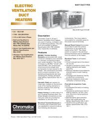
Cold Weather ProductsCommercialWT W
- Page 5 and 6:
ivCold Weather Products
- Page 7 and 8:
LUHHorizontal Blower Heater (cont
- Page 9 and 10:
ComfortLUH Horizontal Blower Heater
- Page 11 and 12:
HVHHorizontal or VerticalDischarge
- Page 13 and 14:
ComfortHVH Horizontal or Vertical D
- Page 15 and 16:
ComfortHVH Horizontal or Vertical D
- Page 17 and 18:
ComfortKUHHorizontal Blower Heater
- Page 19 and 20:
ComfortKUHHorizontal BlowerHeater (
- Page 21 and 22:
ComfortUBHigh Capacity HorizontalBl
- Page 23 and 24:
ComfortUB High Capacity Horizontal
- Page 25 and 26:
ComfortVUHVertical DeliveryBlower H
- Page 27 and 28:
ComfortVUHDiffuser Selection & Heat
- Page 29 and 30:
ComfortHD3DHose Down CorrosionResis
- Page 31 and 32:
ComfortHD3DHose Down Corrosion Resi
- Page 33 and 34:
CXH-AExplosion Proof Blower Heaterf
- Page 35 and 36:
ComfortCXH-AExplosion ProofBlower H
- Page 37 and 38:
ComfortCXH-AExplosion ProofBlower H
- Page 39 and 40:
ComfortDRAPortable Spot IndustrialS
- Page 41 and 42:
ComfortDRAPortable Spot IndustrialS
- Page 43 and 44:
ComfortCCHCabinet ConsoleBlower Hea
- Page 45 and 46:
ComfortCCHCabinet ConsoleBlower Hea
- Page 47 and 48:
ComfortHCHWall MountedConvection He
- Page 49 and 50:
ComfortHCHWall MountedConvection He
- Page 51 and 52:
ComfortHHorizontalConvection Heater
- Page 53 and 54:
ComfortCPHHPump HouseConvection Hea
- Page 55 and 56:
ComfortCVEPConvection HeaterFor Haz
- Page 57 and 58:
ComfortCVEP Convection Heater For H
- Page 59 and 60:
ComfortCAF-6Architectural DraftBarr
- Page 61 and 62:
ComfortCCAS-8Architectural Slope To
- Page 63 and 64:
ComfortCCAS-12Architectural Slope T
- Page 65 and 66:
ComfortCAF-12ArchitecturalConvectio
- Page 67 and 68:
ComfortCAF-20Architectural CabinetC
- Page 69 and 70:
ComfortChromaStarInfra-RedRadiant H
- Page 71 and 72:
ComfortChromaStarInfra-RedRadiant H
- Page 73 and 74:
ComfortChromaStarAccessories(cont
- Page 75 and 76:
ComfortRBC-1Overhead RadiantSpace H
- Page 77 and 78:
ComfortRBC-3Fixed Overhead RadiantS
- Page 79 and 80:
ComfortUTUA-LT430” Dia.Round Cros
- Page 81 and 82:
ComfortKRSingle Fixed ElementRadian
- Page 83 and 84:
ControlsWR80-EPExplosion Proof Room
- Page 85 and 86:
ControlsWTLWall MountedResidential
- Page 87 and 88:
Heating CableSRLSelf-RegulatingLow
- Page 89 and 90:
SRLSelf-Regulating LowTemperature (
- Page 91 and 92:
Heating CableSRPSelf-RegulatingProc
- Page 93 and 94:
Heating CableSRM/ESelf-RegulatingMe
- Page 95 and 96:
SRM/ESelf-RegulatingMedium Temperat
- Page 97 and 98:
Heating CableCWMConstant Wattage Me
- Page 99 and 100:
Heating CableMIMineral InsulatedHig
- Page 101 and 102:
MIMineral InsulatedHigh Temperature
- Page 103 and 104:
Heating CableMIMineral Insulated Hi
- Page 105 and 106:
Heating CableHSRLSelf-RegulatingLow
- Page 107 and 108:
Heating CableHSRMSelf-RegulatingMed
- Page 109 and 110:
Heating CableHSRMSelf-RegulatingMed
- Page 111 and 112:
Heating CableSRFApplication & Selec
- Page 113 and 114:
Heating CableSRFSelf-Regulating Fre
- Page 115 and 116:
Heating CableSRF-RGSelf-RegulatingR
- Page 117 and 118:
Heating CableEdge-Cutter ®Roof De-
- Page 119 and 120:
ControlsAPS-4CAutomatic Snow/IceMel
- Page 121 and 122:
ControlsSC-40CSatellite Contactor
- Page 123 and 124:
ControlsGIT-3AGutter IceMelting Con
- Page 125 and 126:
ControlsCIT-1Snow Sensor• Reliabl
- Page 127 and 128:
ControlsSIT-6EPavement Sensor• Re
- Page 129 and 130:
Heating CableU SeriesHeat Trace Con
- Page 131 and 132:
Heating CableU SeriesHeat Trace Con
- Page 133 and 134:
Heating CableU SeriesHeat Trace Con
- Page 135 and 136:
Heating CableDL & EL SeriesConnecti
- Page 137 and 138:
DLIntegrated ConnectionAccessories
- Page 139 and 140:
Heating CableDLIntegrated Connectio
- Page 141 and 142:
Heating CableELStandard ConnectionA
- Page 143 and 144:
Heating CableHLHazardous LocationCo
- Page 145 and 146:
Heating CableB100 & E100Heat Trace/
- Page 147 and 148:
Heating CableRBFHeat Traceor Pipe S
- Page 149 and 150:
Heating CableDLIntegrated Temperatu
- Page 151 and 152: Controls®HTLSHeat Tracing LineSens
- Page 153 and 154: Controls®HTLSTwo, Three and Four-L
- Page 155 and 156: Controls®HTLSThree-Loop Heat Traci
- Page 157 and 158: Controls®HTLSC1D2Series C1D2Heat T
- Page 159 and 160: Controls®HTLSHeat Tracing Line Sen
- Page 161 and 162: ControlsHTLSHeat Tracing Line Sensi
- Page 163 and 164: Controls®HTASHeat Tracing Ambient
- Page 165 and 166: ControlsHTASHeat Tracing Ambient Se
- Page 167 and 168: ControlsFreeze ProtectionHeat Trace
- Page 169 and 170: ControlsFreeze Protection Heat Trac
- Page 171 and 172: ControlsFreeze Protection Heat Trac
- Page 173 and 174: ControlsFreeze ProtectionHeat Trace
- Page 175 and 176: ControlsFreeze ProtectionHeat Trace
- Page 177 and 178: ComponentsPHD & PHDTHeavy Duty Fibe
- Page 179 and 180: SL-BSilicone Rubber InsulatedEnclos
- Page 181 and 182: ComponentsSLDHSilicone RubberInsula
- Page 183 and 184: TechnicalTechnical InformationDeter
- Page 185 and 186: Technical InformationGeneral Indust
- Page 187 and 188: 182TechnicalTechnical InformationTy
- Page 189 and 190: TechnicalTechnical InformationTypic
- Page 191 and 192: TechnicalTechnical InformationRadia
- Page 193 and 194: TechnicalTechnical Information90˚
- Page 195 and 196: TechnicalTechnical Information60˚
- Page 197 and 198: TechnicalTechnical Information60˚
- Page 199 and 200: TechnicalHeat Tracing ProductsIndus
- Page 201: Heat Tracing ProductsApplication &
- Page 205 and 206: TechnicalTechnical InformationDeter
- Page 207 and 208: TechnicalTechnical InformationElect
- Page 209 and 210: TechnicalTechnical InformationWirin
- Page 211 and 212: Reference Data206TechnicalPressure-
- Page 213 and 214: TechnicalReference DataPhysical & T
- Page 215 and 216: TechnicalReference DataEquivalents
- Page 217 and 218: TechnicalTechnical InformationNEMA
- Page 219 and 220: TechnicalTechnical InformationHazar
- Page 221 and 222: TechnicalTechnical InformationHazar
- Page 223 and 224: Technical Notes218
- Page 225 and 226: Cold Weather Technical ProductsInde