Cold Weather Catalog - Chromalox Precision Heat and Control
Cold Weather Catalog - Chromalox Precision Heat and Control
Cold Weather Catalog - Chromalox Precision Heat and Control
- No tags were found...

You also want an ePaper? Increase the reach of your titles
YUMPU automatically turns print PDFs into web optimized ePapers that Google loves.
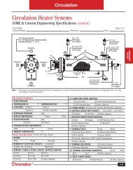
TechnicalTechnical InformationRadiant Infrared <strong>Heat</strong>ing - Comfort <strong>Heat</strong>ingIndoor Spot <strong>Heat</strong>ingInfrared spot heating of work stations <strong>and</strong>personnel in large unheated structures or areashas proven to be economical <strong>and</strong> satisfactory.The following guidelines may be used for spotheating applications (areas with length orwidth less than 50 feet).1. Determine the coldest anticipated insideambient temperature the system mustovercome. If freeze protection is providedby another heating system, thistemperature will be 40°F.2. Determine the equivalent ambienttemperature desired (normally 70°F is thenominal average).3. Subtract 1 from 2 to determine thetheoretical increase in ambient temperature(ΔT ) expected from the infrared system. Ifdrafts are present in the occupied area (airmovement over 44 feet per minute(0.5 mph) velocity), wind shielding orprotection from drafts should beconsidered.4. Determine the area to be heated in ft 2 . Thisis termed the “design or work area” (AD)(Fig. 1).5. Multiply the design area by one watt persquare foot times the theoreticaltemperature increase (ΔT) desired asdetermined in Step 3 (minimum of 12watts per square foot). The design factor ofone watt per square foot density assumes afi xture mounting height of 10 feet. Add 5%for each foot greater than 10 feet inmounting height. Avoid mounting fi xturesbelow 8 feet.6. Determine fi xture mounting locationsa) In areas where the width dimension is25 feet or less, use at least two fixturesmounted opposite each other atthe perimeter of the area <strong>and</strong> tilted at anangle. This provides a greater area ofexposure to the infrared energy bypersonnel in the work area. Tilt thefi xtures so that the upper limit of thefi xture pattern is at approximately six feetabove the center of the work station area(Figure 2).b) When locating fi xtures, be sure toallow adequate height clearance for largemoving equipment such as cranes <strong>and</strong> lifttrucks.c) Avoid directing infrared onto outsidewalls.7. Estimate (tentatively) the radiated patternarea. Add length of fixture to the fi xturepattern width (W) to establish patternlength (L). Pattern Area = L x W (Fig. 3).186Figure 1 — Design AreaMounting HeightAngle ofUniformRadiationWWidth of RadiationPattern8. Divide the design area (Step 4) into thepattern area (Step 7).LQ = Pattern AreaDesign AreaIf the pattern area is equal to or greaterthan the design area, quotient (Q) will beequal to or greater than 1 <strong>and</strong> coverage isadequate. If Q is less than 1, the designarea exceeds the pattern area of individualfi xtures. Adjust the heater locations <strong>and</strong>patterns or add additional fixtures withpatterns overlapping as necessary, toensure adequate coverage.9. Multiply quotient (Q in Step 8) by theincrease in theoretical temperature (ΔT ofStep 3) by the design area (AD of Step 4) todetermine the amount of radiation to beinstalled.Radiation (Watts) = Q x ΔT x AD10. Many Types of radiant heaters areavailable for comfort heating applicationsincluding ceiling, wall <strong>and</strong> portable floorst<strong>and</strong>ing models. Choose specific fixturesfrom the product pages. It is preferred thathalf the wattage requirements be installedon each side of the work station in thedesign area.<strong>Control</strong>s — Manual control by percentagetimers may be adequate for a small installation.To provide better control of comfort levels invarying ambient temperatures, divide the totalheat required into two or three circuits so thateach fi xture or heating element circuit can beswitched on in sequence. Staging can beW10'Figure 2 — Tilted Infrared Fixturesfor Spot <strong>Heat</strong>ingWFigure 3 — Pattern Area11.5'W/2FixtureLocationW/2accomplished by using multistage air thermostatsset at different temperatures.Indoor Area <strong>Heat</strong>ingLIn many industrial environments, area heating(areas with length or width greater than 50ft) can be accomplished economically withmultiple infrared heaters. For quick estimates,determine the minimum inside temperature<strong>and</strong> use a factor of 0.5 watts per square footof design area for each degree of theoreticaltemperature. If the calculated heat loss of thestructure, including infi ltration or ventilation air,is less than the quick estimate, select the lowervalue. Locate heaters uniformly throughout thearea with at least a 30% overlap in radiationpattern.Outdoor Spot <strong>Heat</strong>ing60° Reflector22° TiltThe same guidelines outlined under IndoorSpot <strong>Heat</strong>ing should be followed except thatwatts per square foot for each degree of theoreticalambient temperature increase should bedoubled (approximately 2 watts per square footfor each 1°F). This factor applies to outdoorheating applications with little or no wind chilleffect on personnel. If wind velocities are a factorin the application, determine the equivalentair temperature from the Wind Chill Chart inNEMA publication HE3-1971 or other informationsource.Note — Increasing the infrared radiation tomassive levels to offset wind chill can creatediscomfort <strong>and</strong> thermal stress. In outdoorexposed applications, a wind break or shieldingis usually more effective.