Cold Weather Catalog - Chromalox Precision Heat and Control
Cold Weather Catalog - Chromalox Precision Heat and Control
Cold Weather Catalog - Chromalox Precision Heat and Control
- No tags were found...

You also want an ePaper? Increase the reach of your titles
YUMPU automatically turns print PDFs into web optimized ePapers that Google loves.
The Right Products <strong>and</strong> Solutionsfor Your Applications<strong>Cold</strong> <strong>Weather</strong>productswww.chromalox.com
<strong>Cold</strong> <strong>Weather</strong> ProductsTable of ContentsComfort <strong>Heat</strong>ersForced Air <strong>Heat</strong>ersIndustrialLUH Horizontal Blower <strong>Heat</strong>er 1HVH Horizontal or Vertical Blower <strong>Heat</strong>er 5KUH Horizontal Blower <strong>Heat</strong>er 11UB High Capacity Horizontal Blower <strong>Heat</strong>er 15VUH Vertical Delivery Blower <strong>Heat</strong>er 20Harsh EnvironmentHD3D Hose Down Corrosion Resistant Blower <strong>Heat</strong>er 24CXH-A Explosion Proof Blower <strong>Heat</strong>er for Hazardous Locations 27PortableDRA Portable Industrial Blower <strong>Heat</strong>er 34HF Portable Blower <strong>Heat</strong>er 37CommercialCCH Cabinet Console Blower <strong>Heat</strong>er 38FLEXIBLEConvection <strong>Heat</strong>ersIndustrialHCH Wall Mounted Convection <strong>Heat</strong>er 42EH Convection <strong>Heat</strong>er Without Thermostat 45HVT Convection <strong>Heat</strong>er With Thermostat 45H Horizontal Convection <strong>Heat</strong>er 46V Vertical Convection <strong>Heat</strong>er 47Special PurposeCPHH Pump House Convection <strong>Heat</strong>er 48Harsh EnvironmentCVEP Explosion Proof Convection <strong>Heat</strong>er 50FPEP Explosion Proof Convection <strong>Heat</strong>er - Single Element 54CEP-15 Explosion Proof Convection <strong>Heat</strong>er - Dual Element 54ArchitecturalCAF-6 Draft Barrier Convection <strong>Heat</strong>er 55CCAS-8 Slope Top Convection <strong>Heat</strong>er 57CCAS-12 Slope Top Convection <strong>Heat</strong>er 59CAF-12 Square Top Convection <strong>Heat</strong>er 61CAF-20 Cabinet Convection <strong>Heat</strong>er 63Radiant <strong>Heat</strong>ersIndustrial/CommercialSTAR ChromaStar Infra-Red Radiant <strong>Heat</strong>ers 65Portable Radiant <strong>Heat</strong>ers 66Fixed Radiant <strong>Heat</strong>ers 67Accessories 68RBC-1 Overhead Radiant Space <strong>Heat</strong>er 71RBC-3 Fixed Overhead Radiant <strong>Heat</strong>er 73UTUA-LT .430" Dia. Round Cross- Section Tubular Replacement Element 75SKR Fixed Single Element Radiant <strong>Heat</strong>er 76KR Fixed Single Element Radiant <strong>Heat</strong>er 77Thermostats & <strong>Control</strong>sGeneral PurposeWR-80 / WR-90 Wall Thermostat 78Hazardous AreaWR-80EP Wall Thermostat 79i
<strong>Cold</strong> <strong>Weather</strong> ProductsCommercialWT Wall Thermostat - Line Voltage 80WTL Wall Thermostat - Low Voltage 81Hose DownWCRT Wall Thermostat 82<strong>Heat</strong> Trace & <strong>Control</strong>sCableIndustrialSRL Self-Regulating Low Temperature Cable 83SRM/E Self-Regulating Medium Temperature Cable 86CWM Constant Wattage Medium Temperature Cable 89MI Mineral Insulated High Temperature Cable 92Hazardous AreaHSRL Self-Regulating Low Temperature Cable 96HSRM Self-Regulating Medium Temperature Cable 99CommercialSRF Self-Regulating Freeze Protection Cable & Accessories 102SRF-RG Self-Regulating Roof & Gutter Cable Accessories 107New! Edge-Cutter Roof De-Icing System 109Snow Melting <strong>Control</strong>sAPS-4 Automatic Snow <strong>and</strong> Ice Melting System <strong>Control</strong>ler 111SC-40 Satellite Contactor 112GIT-4 Gutter Ice Melting <strong>Control</strong>ler 113CIT-1 Snow Sensor 114LCD-1 Snow Switch 115SIT-6E Pavement Sensor 116RCU-1 Remote <strong>Control</strong> Unit 117Connection AccessoriesNew! U Series <strong>Heat</strong> Trace Connection System Accessories 118DL & EL Connection Accessories 122DL Integrated Connection Accessories 123EL St<strong>and</strong>ard Connection Accessories 127DL & EL General Application Accessories 129HL Hazardous Location Connection Kits 130ThermostatsB100 & E100 Freeze Protection Thermostats 132RBF <strong>Heat</strong> Trace or Pipe Sensor 134<strong>Control</strong>sDL Integrated Temperature <strong>Control</strong>s 135HTLS Single-Loop Line Sensing <strong>Control</strong> Panel 138HTLS Dual-Loop Line Sensing <strong>Control</strong> Panel 140HTLS Three-Loop Line Sensing <strong>Control</strong> Panel 142HTLS Four-Loop Line Sensing <strong>Control</strong> Panel 143HTLSC1D2 Series C1D2 Line Sensing <strong>Control</strong> Panels 144HTLS Multi-Loop Line Sensing <strong>Control</strong> Panels 146HTAS Multi-Loop Ambient Sensing <strong>Control</strong> Panels 150FPAS, FPLS, FPASM, FPLSM Freeze Protection <strong>Heat</strong> Trace Panels 154Drum & Flexible <strong>Heat</strong>ers<strong>Heat</strong>ersPHD & PHDT Heavy Duty Fiberglass Woven Drum <strong>Heat</strong>er 164IBG Flexible Thermal Drum Insulation Blanket <strong>Heat</strong>er 165SL-B Silicone Rubber Insulated Enclosure & Air <strong>Heat</strong>er 166SLDH Silicone Rubber Insulated Drum <strong>Heat</strong>er 167ii
<strong>Cold</strong> <strong>Weather</strong> ProductsTechnical SectionComfort <strong>Heat</strong>ing Products<strong>Heat</strong> Transfer Fundamentals & Thermodynamic Properties 169Determining <strong>Heat</strong> Energy Requirements 170General Industrial Sizing Guide 172Typical Outside Deisgn Temperatures for the US 173Radiant Infrared <strong>Heat</strong>ing- Comfort <strong>Heat</strong>ing 178Watt Density for Typical Applications vs. Temperature Rise 179Snow <strong>Control</strong> Design Guidelines 179Refl ector Tables for Infrared <strong>Heat</strong>ers 180FLEXIBLE<strong>Heat</strong> Tracing ProductsApplication & Selection Guidelines 185Determining <strong>Heat</strong> Energy Requirements 189General Technical InformationProperties of Steam 193Electrical Fundamentals & Three Phase Calculations 194Three Phase Equations & <strong>Heat</strong>er Wiring Diagrams 195Wiring Practices for Electric <strong>Heat</strong>ers 196Reference DataPressure-Temperature Ratings of Common Flange Materials 198Physical & Thermodynamic Properties of Common Liquids 199Physical & Thermodynamic Properties of Common Solids 200Equivalents & Conversions 202Engineering Constants & Conversions 203NEMA Enclosures, Hazardous Location <strong>Heat</strong>ers, Electric <strong>Heat</strong>er Applications 204Terms of Sales & Warranty Information 209Index 213iii
iv<strong>Cold</strong> <strong>Weather</strong> Products
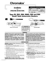
ComfortLUHHorizontalBlower <strong>Heat</strong>erE7061FORCED AIR• 2.6 - 45 kW• 8,900 - 153,000 Btuh• 208, 240, 277, 480 <strong>and</strong> 600 Volt• 1 or 3 Phase• Wall or Ceiling MountedConfigurationsDescriptionType LUH self-contained heater provides quiet,reliable fan-forced heating in all types of commercial<strong>and</strong> industrial applications.Applications• Shipping <strong>and</strong> Receiving Areas• Pump Houses• Power Generating Stations• Aircraft Hangers• Factories• Warehouses• GaragesConstructionDie Formed Cabinet — Heavy 18 gaugesteel, phosphate undercoated for corrosionresistance <strong>and</strong> fi nished in almond polyesterpowder coat.Louvers — Individually adjustable louversdirect air fl ow up or down as needed.Fintube <strong>Heat</strong>ing Elements have corrosionresistant steel fi ns that are furnace brazed tothe tubular element to assure long life <strong>and</strong>superior heat transfer.Refer toWR-80, RTC, WR-90in the <strong>Control</strong>s section.Fan Motor — Totally enclosed fan motor israted for continuous duty with built-in thermalcutout <strong>and</strong> operates on same voltage as theheating circuit.Dynamically Balanced Fan is attached withrubber vibration insulators for smooth, quietoperation. Blade pitch is carefully selected sothat the volume of air moved results in theoptimum discharge air temperature.Features• Sub-divided Circuits with Individual FuseProtection — St<strong>and</strong>ard on all heaters witha total current draw of 48 Amps or greater.The fuse compartment is convenientlylocated for easy access.• Integral 120V <strong>Control</strong> Transformer —St<strong>and</strong>ard on 480V models, eliminates theneed for an external control source (24Voptional).• Heavy Duty Magnetic Contactors are st<strong>and</strong>ardon all models.• Thermal Cutouts open the control circuit<strong>and</strong> disconnect power to the heating elementsif overheating occurs. AutomaticReset allows the control circuit to reclose<strong>and</strong> restore power when temperature returnsto normal.• Field Convertible — Combination 208/240V<strong>and</strong> 1 or 3 phase operation through 10 kW.• Mounting Confi gurations — Recessedwelded fasteners on top of the heater cabinetare internally threaded for suspension of unitwith threaded rods. Ceiling <strong>and</strong> UniversalWall Swivel brackets are optional. The ceilingbracket lets you mount heater directlyto ceiling or over-head member, simply <strong>and</strong>easily. The swivel mounting allows you toreadily adjust the direction of warm air fl owfor maximum comfort up to 180 degrees.Optional Features (Factory Installedor Field Installation Kits)• Summer Fan Switch Kit — Field installablefor circulating warm stratifi ed air. Availablefor all models.• Thermostat Kit — Field installable on allmodels. Range 40°F - 90°F.• Power Disconnect Kit — Field installableswitch enables power to be disconnectedwhile servicing heater. 40, 80 <strong>and</strong> 100 Ampmodels available. Mounts in the back of theheater.• Ceiling Bracket(shown above)• Wall Mounting BracketAdvantages• Self Contained• Versatile, Flexible <strong>and</strong> High Performance• Easy Installation• Minimum Maintenance• Long Life• Attractive AppearanceBecause it has individually adjustable dischargelouvers to direct air fl ow,<strong>and</strong> can be wall or ceiling (plus swivel)mounted, the LUH heater may be usedin a variety of heating applications:• Primary <strong>Heat</strong>ing• Supplementary <strong>Heat</strong>ing• Dual System <strong>Heat</strong>ing• Spot <strong>Heat</strong>ing• Entryway Air-Curtain <strong>Heat</strong>ing1
LUHHorizontal Blower <strong>Heat</strong>er (cont’d.)Dimensions (Inches)ComfortF(4) Welded fasteners 2for threaded rodJmounting tooverhead steel.IWall Mounted Universal Bracket(4) 13/32" dia. wallmounting holes. 1Stop for limiting rotation.RSP6"Min.to WallKGHSwivel bolt permits heater to berotated to face desired direction.Four bolts are provided for field attachmentof swivel bracket towelded fasteners on top of unit.QWallLineEBWall Mounted <strong>Heat</strong>ersACDMin.to WallDimensions (In.)WallWt.<strong>Heat</strong>erP Q R S T Bracket PCN Stock (Lbs.)LUH-02 to -05 1-3/4 21-1/2 6-3/4 5-1/2 14-15/16 WUH-01A 303474 S 3LUH-07, 10, 12, 15 2 28-7/16 9-1/2 8-3/8 22-1/4 WUH-02 300484 S 5LUH-20, 25 2 32 9-1/2 8-3/8 22-1/4 WUH-02 300484 S 7LUH-30, 35, 40, 45 5-1/2 28-11/16 5 3-1/2 33-1/4 WUH-03 300492 S 10Ceiling Mounted <strong>Heat</strong>ers6"Minimum mounting heightis 7 feet from floor.Ceiling Mounted(1) 11/16" dia.swivelmountinghole.Notes —1. Wall mounting fasteners to be supplied by customer.2. Threaded rod to be supplied by customer.Dimensions (In.)<strong>Heat</strong>er A B C D E F G H I J K M N U V WCeilingBracket PCN StockWt.(Lbs.)LUH-02 to -05 16 13-1/8 8-7/8 11-5/8 10-3/4 9-3/4 5-1/2 3-13/16 4-1/2 4-15/16 6-5/8 6 4-7/16 4 4-1/2 10-1/2 WUH-04A 303466 S 1LUH-07, 10, 12, 15 20-1/2 17-1/4 11-1/2 16-3/8 14-3/8 12-3/8 8-1/4 4-1/2 6-1/4 7-7/16 8-5/8 8 6-1/4 6 7-1/4 16 WUH-05 300513 S 2LUH-20, 25 24 20-1/8 11-1/2 20-1/2 16-3/4 16 8-1/4 6 6-1/4 12 10-1/16 8 6-1/4 6 7-1/4 16 WUH-05 300513 S 3LUH-30, 35, 40, 45 24 20-1/8 17 26 16-3/4 16 8-1/4 6 11-3/4 12 10-1/16 13-3/4 9-5/16 6 7-1/4 21 WUH-06 300521 S 3VUANMTWOptional <strong>Control</strong> Accessories & Remote ThermostatsFan Only Operation KitsSummer Fan SwitchThermostat KitNote — A fan only operation (optional) is available bymeans of a built-in switch or by external control.(2 - 15 kW) (20 - 45 kWWt.Summer Fan Switch Model PCN Model PCN Stock (Lbs.)Internal 208 - 277V ISFS-02 2 305007 ISFS-02 305007 S 0.25External 1 with Relay ESFS-40 305015 ESFS-40A 305058 S 0.5(24V control)External 1 with Relay ESFS-41 305023 ESFS-41A 305066 S 0.5(120V control)External 1 with Relay ESFS-42 305031 ESFS-42A 305074 NS 0.5(240V control)External 1 with Relay ESFS-47 305040 — — S 0.5(277V control)1. Kit includes wall plate (discard plate if switch is to be installed on heater).2. Do not use for 480V rated heaters. 480V heaters require fan relay optionwith proper control voltage relay coil.Thermostat KitsPower Disconnect Kits3 Pole, 600VRatingModel PCN StockWt.(Lbs.)LUH-TK1 (SPST) 301129 S 0.25LUH TK2 (DPST) 300530 S 0.25Mounting LimitationsModel Rating PCN StockWt.(Lbs.)EDS-1 40 Amp* 303431 S 0.5EDS-2 80 Amp 303440 NS 0.5EDS-3 100 Amp 303458 NS 1* EDS-1 Rating for 480V or less is 50 Amp.Hazardous Atmosphere — Unit heaters should not be used inpotentially explosive atmospheres. Corrosive Atmosphere —The finishis not intended for direct salt spray exposure in marine applicationsor the highly corrosive atmospheres of greenhouses, swimmingpools, chemical storage bins, etc. Mounting Height — Do not installunit heaters above recommended maximum mounting height.Obstructions must not block unit heater air inlet or discharge.2
ComfortLUH Horizontal Blower <strong>Heat</strong>er (cont’d.)Specifications <strong>and</strong> Ordering InformationElectrical (60 Hz)MotorAir DeliveryOrderingCktTemp. Horiz. Mtg. 5&Rise Throw HeightWt.kW Volts Phase Amps 4 Volts Phase HP RPM CFM FPM (°F) (Ft.) (Ft.) Model Stock PCN (Lbs.)2.6 208 1 - 1 13.1 208 1 1/40 1,650 410 880 21 12 8 LUH-02-81-34 S 303001 322.0/2.6 208/240 1 - 1 11.4 2 240 1 1/40 1,650 410 880 21 12 8 LUH-02-21-34 S 303010 322.6 277 1 - 1 9.6 277 1 1/30 1,550 360 770 24 12 8 LUH-02-71-35 S 303028 324 208 1 - 1 19.8 208 1 1/40 1,650 410 880 31 12 8 LUH-04-81-34 S 303036 324 208 1 - 3 3 11.7 208 1 1/40 1,650 410 880 31 12 8 LUH-04-83-34 S 303044 323/4 208/240 1 - 1 17.2 2 240 1 1/40 1,650 410 880 31 12 8 LUH-04-21-34 S 303052 323/4 208/240 1 - 3 3 10.2 2 240 1 1/40 1,650 410 880 31 12 8 LUH-04-23-34 S 303060 324 277 1 - 1 14.6 277 1 1/30 1,550 360 770 35 12 8 LUH-04-71-35 S 303079 324 480 1 - 3 5.1 480 1 1/35 1,550 380 815 33 12 8 LUH-04-43-32 S 303087 325 208 1 - 1 24.6 208 1 1/40 1,650 410 880 39 12 8 LUH-05-81-34 S 303095 325 208 1 - 3 3 14.5 208 1 1/40 1,650 410 880 39 12 8 LUH-05-83-34 S 303108 323.75/5 208/240 1 - 1 21.4 240 1 1/40 1,650 410 880 39 12 8 LUH-05-21-34 S 303116 323.75/5 208/240 1 - 3 3 12.6 240 1 1/40 1,650 410 880 39 12 8 LUH-05-23-34 NS 303124 325 277 1 - 1 18.3 277 1 1/30 1,550 360 770 44 12 8 LUH-05-71-35 NS 303132 325 480 1 - 3 6.3 480 1 1/35 1,550 380 815 42 12 8 LUH-05-43-32 S 303140 327.5 208 1 - 1 3 36.5 208 1 1/15 1,725 850 1,040 28 27 8 LUH-07-81-34 AS 303159 507.5 208 1 - 3 21.3 208 1 1/15 1,275 850 1,040 28 27 8 LUH-07-83-34 S 303167 505.6/7.5 208/240 1 - 1 3 31.7 2 240 1 1/15 1,725 850 1,040 28 27 8 LUH-07-21-34 S 303175 505.6/7.5 208/240 1 - 3 18.5 2 240 1 1/15 1,725 850 1,040 28 27 8 LUH-07-23-34 AS 303183 507.5 277 1 - 1 27.7 277 1 1/15 1,550 750 920 32 27 8 LUH-07-71-35 NS 303191 507.5 480 1 - 3 9.9 480 3 1/15 1,725 850 1,040 28 27 8 LUH-07-43-32 S 303204 507.5 600 1 - 3 7.6 575 3 1/3 1,725 850 1,040 28 27 8 LUH-07-63-32 NS — 509.7 208 1 - 1 3 47.1 208 1 1/15 1,725 850 1,040 37 27 9 LUH-10-81-34 AS 303212 509.7 208 1 - 3 27.4 208 1 1/15 1,725 850 1,040 37 27 9 LUH-10-83-34 S 303220 507.5/10 208/240 1 - 1 3 42.1 2 240 1 1/15 1,725 850 1,040 37 27 9 LUH-10-21-34 S 303239 507.5/10 208/240 1 - 3 24.5 2 240 1 1/15 1,725 850 1,040 37 27 9 LUH-10-23-34 AS 303247 5010 480 1 - 3 12.9 480 3 1/15 1,725 850 1,040 37 27 9 LUH-10-43-32 S 303255 5010 600 1 - 3 10.6 575 3 1/3 1,725 850 1,040 37 27 9 LUH-10-63-32 NS — 5012.5 208 1 - 3 35.2 208 1 1/15 1,725 850 1,040 47 27 9 LUH-12-83-34 S 303263 509.3/12.5 208/240 1 - 3 30.6 240 1 1/15 1,725 850 1,040 47 27 9 LUH-12-23-34 AS 303271 5012.5 480 1 - 3 15.9 480 3 1/15 1,725 850 1,040 47 27 9 LUH-12-43-32 S 303280 5012.5 600 1 - 3 12.6 575 3 1/3 1,725 850 1,040 47 27 9 LUH-12-63-32 NS — 5015 208 1 - 3 42.1 208 1 1/15 1,725 850 1,040 56 27 10 LUH-15-83-34 AS 303298 5011.25/15 208/240 1 - 3 36.6 2 240 1 1/15 1,725 850 1,040 56 27 10 LUH-15-23-34 NS 303300 5015 480 1 - 3 19.0 480 3 1/15 1,725 850 1,040 56 27 10 LUH-15-43-32 S 303319 5015 600 1 - 3 15.6 575 3 1/3 1,725 850 1,040 56 27 10 LUH-15-63-32 NS — 5014.5/19.4 208/240 1 - 3 48.0 2 240 3 1/3 1,725 1,240 1,160 53 31 11 LUH-20-23-34 NS 303327 7320 480 1 - 3 25.0 480 3 1/3 1,725 1,240 1,160 53 31 11 LUH-20-43-32 S 303335 7320 600 1 - 3 19.6 575 3 1/3 1,725 1,240 1,160 53 31 11 LUH-20-63-32 NS — 7325 480 1 - 3 31.0 480 3 1/3 1,725 1,350 1,260 60 31 12 LUH-25-43-32 S 303343 7325 600 1 - 3 24.6 575 3 1/3 1,725 1,350 1,260 60 31 12 LUH-25-63-32 NS — 7330 208 2 - 3 85.2 240 3 1/3 1,725 1,555 1,450 64 46 13 LUH-30-83-34 NS 303351 10622.5/30 208/240 2 - 3 74.0 2 240 3 1/3 1,725 1,555 1,450 64 46 13 LUH-30-23-34 NS 303360 10630 480 2 - 3 37.1 480 3 1/3 1,725 1,555 1,450 64 46 13 LUH-30-43-32 S 303378 10630 600 2 - 3 29.6 575 3 1/3 1,725 1,555 1,450 64 46 13 LUH-30-63-32 NS — 10626.25/35 208/240 2 - 3 86.0 2 240 3 1/3 1,725 1,555 1,450 71 45 14 LUH-35-23-34 NS 303386 10635 480 2 - 3 43.1 480 3 1/3 1,725 1,555 1,450 71 45 14 LUH-35-43-32 S 303394 10635 600 2 - 3 34.7 575 3 1/3 1,725 1,555 1,450 71 45 14 LUH-35-63-32 NS — 10628.5/38 208/240 2 - 3 93.3 240 3 1/3 1,725 1,555 1,450 84 44 15 LUH-40-23-34 NS 303407 10639 480 2 - 3 47.9 480 3 1/3 1,725 1,555 1,450 84 44 15 LUH-40-43-32 S 303415 10640 600 2 - 3 39.7 575 3 1/3 1,725 1,555 1,450 84 44 15 LUH-40-63-32 NS — 10645 480 2 - 3 55.1 480 3 1/3 1,725 1,555 1,450 94 42 17 LUH-45-43-32 S 303423 10645 600 2 - 3 43.7 575 3 1/3 1,725 1,555 1,450 94 42 17 LUH-45-63-32 NS — 106Stock Status: S = stock AS = assembly stock NS = non-stockTo Order—Specify model, PCN, kW, volts, phase <strong>and</strong> quantity.1. For motor data, see table.2. 208V amperage is 86% of 240V value.3. Models can be field wired for 1 or 3 phase.4. Includes motor Amps.5. Maximum mounting height for effective heat distribution. Minimum height is 7 feet.Other Notes —A. All heaters have built-in contactors <strong>and</strong> stock 480V models have built-in control transformers <strong>and</strong> contactor with 120V holdingcoils. All stock 208 <strong>and</strong> 240V models have 208/240V holding coils. All stock 277V models have 277V holding coils.B. Optional contactors available with 120 or 24V holding coils on made-to-order models, contact your Local <strong>Chromalox</strong> Sales office.C. When total heater capacity exceeds 48 Amps, built-in fusing is provided behind a hinged <strong>and</strong> latched door in the side whichallows easy access.FORCED AIR3
ComfortLUH Horizontal Blower <strong>Heat</strong>er (cont’d.)Recommended <strong>Control</strong> OptionsKitsPCNDescription ThermostatFanOnlyRemoteFanDisconnect303220 LUH-10-83-34-00 208V 3P 10kW LUH-TK1 ISFS-02 ESFS-42 EDS-1303239 LUH-10-21-34-00 240V 1P 10kW LUH-TK1 ISFS-02 ESFS-42 EDS-2303247 LUH-10-23-34-00 240V 3P 10kW LUH-TK1 ISFS-02 ESFS-42 EDS-1303255 LUH-10-43-32-00 480V 3P 10kW LUH-TK1 ESFS-41 ESFS-41 EDS-1303263 LUH-12-83-34-00 208V 3P 12.5kW LUH-TK1 ISFS-02 ESFS-42 EDS-1303271 LUH-12-23-34-00 240V 3P 12.5kW LUH-TK1 ISFS-02 ESFS-42 EDS-1303280 LUH-12-43-32-00 480V 3P 12.5kW LUH-TK1 ESFS-41 ESFS-41 EDS-1303298 LUH-15-83-34-00 208V 3P 15kW LUH-TK1 ISFS-02 ESFS-42 EDS-2303300 LUH-15-23-34-00 240V 3P 15kW LUH-TK1 ISFS-02 ESFS-42 EDS-1303319 LUH-15-43-32-00 480V 3P 15kW LUH-TK1 ESFS-41 ESFS-41 EDS-1303327 LUH-20-23-34-00 240V 3P 20kW LUH-TK1 ISFS-02 ESFS-42A EDS-2303335 LUH-20-43-32-00 480V 3P 20kW LUH-TK1 ESFS-41A ESFS-41A EDS-1303343 LUH-25-43-32-00 480V 3P 25kW LUH-TK1 ESFS-41A ESFS-41A EDS-1303351 LUH-30-83-34-00 208V 3P 30kW LUH-TK1 ISFS-02 ESFS-42A EDS-3303360 LUH-30-23-34-00 240V 3P 30kW LUH-TK1 ISFS-02 ESFS-42A EDS-2303378 LUH-30-43-32-00 480V 3P 30kW LUH-TK1 ESFS-41A ESFS-41A EDS-1303386 LUH-35-23-34-00 240V 3P 35kW LUH-TK1 ISFS-02 ESFS-42A EDS-3303394 LUH-35-43-32-00 480V 3P 35kW LUH-TK1 ESFS-41A ESFS-41A EDS-2303407 LUH-40-23-34-00 240V 3P 40kW LUH-TK1 ISFS-02 ESFS-42A EDS-3303415 LUH-40-43-32-00 480V 3P 40kW LUH-TK1 ESFS-41A ESFS-41A EDS-2303423 LUH-45-43-32-00 480V 3P 45kW LUH-TK1 ESFS-41A ESFS-41A EDS-2KitsPCNDescription ThermostatFanOnlyRemoteFanDisconnect303001 LUH-02-81-34-00 208V 1P 2.6kW LUH-TK1 ISFS-02 ESFS-42 EDS-1303010 LUH-02-21-34-00 240V 1P 2.6kW LUH-TK1 ISFS-02 ESFS-42 EDS-1303028 LUH-02-71-35-00 277V 1P 2.6kW LUH-TK1 ISFS-02 ESFS-47 EDS-1303036 LUH-04-81-34-00 208V 1P 4kW LUH-TK1 ISFS-02 ESFS-42 EDS-1303044 LUH-04-83-34-00 208V 3P 4kW LUH-TK1 ISFS-02 ESFS-42 EDS-1303052 LUH-04-21-34-00 240V 1P 4kW LUH-TK1 ISFS-02 ESFS-42 EDS-1303060 LUH-04-23-34-00 240V 3P 4kW LUH-TK1 ISFS-02 ESFS-42 EDS-1303079 LUH-04-71-35-00 277V 1P 4kW LUH-TK1 ISFS-02 ESFS-47 EDS-1303087 LUH-04-43-32-00 480V 3P 4kW LUH-TK1 ESFS-41 ESFS-41 EDS-1303095 LUH-05-81-34-00 208V 1P 5kW LUH-TK1 ISFS-02 ESFS-42 EDS-1303108 LUH-05-83-34-00 208V 3P 5kW LUH-TK1 ISFS-02 ESFS-42 EDS-1303116 LUH-05-21-34-00 240V 1P 5kW LUH-TK1 ISFS-02 ESFS-42 EDS-1303124 LUH-05-23-34-00 240V 3P 5kW LUH-TK1 ISFS-02 ESFS-42 EDS-1303132 LUH-05-71-35-00 277V 1P 5kW LUH-TK1 ISFS-02 ESFS-47 EDS-1303140 LUH-05-43-32-00 480V 3P 5kW LUH-TK1 ESFS-41 ESFS-41 EDS-1303159 LUH-07-81-34-00 208V 1P 7.5kW LUH-TK1 ISFS-02 ESFS-42 EDS-1303167 LUH-07-83-34-00 208V 3P 7.5kW LUH-TK1 ISFS-02 ESFS-42 EDS-1303175 LUH-07-21-34-00 240V 1P 7.5kW LUH-TK1 ISFS-02 ESFS-42 EDS-1303183 LUH-07-23-34-00 240V 3P 7.5kW LUH-TK1 ISFS-02 ESFS-42 EDS-1303191 LUH-07-71-35-00 277V 1P 7.5kW LUH-TK1 ISFS-02 ESFS-47 EDS-1303204 LUH-07-43-32-00 480V 3P 7.5kW LUH-TK1 ESFS-41 ESFS-41 EDS-1303212 LUH-10-81-34-00 208V 1P 10kW LUH-TK1 ISFS-02 ESFS-42 EDS-2When ordering LUH heaters, specify the model number <strong>and</strong> corresponding PCN (Product Code Number). If controls or thermostat/fan options are required, designate these options inthe model number when ordering, as shown below. Always specify voltage, phase <strong>and</strong> kW by listing them on the purchase order product specifi cations.Model Numbers<strong>Chromalox</strong> Horizontal Unit <strong>Heat</strong>er<strong>Heat</strong>ing Elements02 = 2.6 kW 10 = 10.0 kW 25 = 25.0 kW 45 = 45.0 kW04 = 4.0 k W 12 = 12.5 kW 30 = 30.0 kW05 = 5.0 kW 15 = 15.0 kW 35 = 35.0 kW07 = 7.5 kW 20 = 20.0 kW 40 = 40.0 kW<strong>Heat</strong>er Voltage <strong>and</strong> Phase81 = 208V, 1 Phase 71 = 277V, 1 Phase83 = 208V, 3 Phase 43 = 480V, 3 Phase21 = 240V, 1 Phase 63 = 600V, 3 Phase23 = 240V, 3 Phase<strong>Control</strong>0 0 No Contactor(s)3 0 24V <strong>Control</strong> Internal Transformer3 1 24V <strong>Control</strong> Externally Supplied3 2 120V <strong>Control</strong> Internal Transformer3 3 120V <strong>Control</strong> Externally Supplied3 4 208/240V <strong>Control</strong> Internally Supplied, No Transformer3 5 277V <strong>Control</strong> Internally Supplied<strong>Control</strong>0 0 No Thermostat, No Summer Fan Switch4 0 Internal Thermostat Only4 1 Internal Therm. <strong>and</strong> Internal Sum. Fan Sw.4 2 External Sum. Fan Sw. Only (Not 480V)4 3 External Sum. Fan Sw. <strong>and</strong> Fan Relay (All Volts)4 4 Rem. Fan Sw. <strong>and</strong> Internal Therm. (Not 480V)4 5 Rem. Fan Sw., Fan Relay <strong>and</strong> Int. Therm. (All Volts)D, E, F, G4 6 Internal Sum. Fan Sw. (Not 480 V)4 7 Internal Sum. Fan Sw., Fan Relay (All Volts)Disconnect Switch1 40 Amp2 80 Amp3 100 AmpLUH 05 21 34 41 1 Typical Model Number4
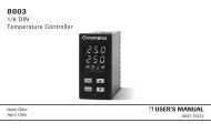
ComfortHVHHorizontal or VerticalDischarge Fan ForcedUnit <strong>Heat</strong>erFORCED AIR• 2.6 - 15 kW• 8,900 – 51,180 Btuh• 208, 240, 277, 480 <strong>and</strong> 600 Volt• 1 or 3 Phase• Vertical or Horizontal Airflow• Wall or Ceiling MountedConfigurations• UL Listed <strong>and</strong> CSA Certified(North America)• CE Certified (Europe)DescriptionType HVH self-contained blower heaterprovides quiet, reliable fan-forced heating in alltypes of commercial <strong>and</strong> industrial applications.Applications• Shipping <strong>and</strong> Receiving Areas• Pump Houses• Power Generating Stations• Aircraft Hangars• Factories• Warehouses• GaragesConstructionCabinet - Heavy 20 gauge steel, phosphate undercoatedfor corrosion resistance <strong>and</strong> finishedin a two-tone gray polyester powder coat.Louvers - Individually adjustable integral louversdirect air fl ow up or down as needed.Fintube <strong>Heat</strong>ing Elements have corrosionresistant steel fi ns that are furnace brazed tothe tubular heating element to assure long life<strong>and</strong> superior heat transfer.Fan Motor - Totally enclosed fan motor israted for continuous duty with built-in thermalcutout <strong>and</strong> operates on the same voltage asthe heating circuit.Dynamically Balanced Fan ensures smooth,quiet operation. Blade pitch is carefully selectedso that the volume of air moved results in theoptimum discharge air temperature. Pullthroughair fl ow design draws air acrossheating elements for more even air fl ow distribution<strong>and</strong> cooler element operation.Features• Integral 24V <strong>Control</strong> Transformer is st<strong>and</strong>ardon 480V models <strong>and</strong> eliminates the need foran external control source( 120V is optional).• Heavy Duty Magnetic Contactors arest<strong>and</strong>ard on all models except 2.6 thru 5 kWsingle phase models, except for 480V models.• Linear Thermal Cutouts open the controlcircuit <strong>and</strong> disconnect power to the heatingelements if overheating occurs. AutomaticReset allows the control circuit to reclose<strong>and</strong> restore power when temperature returnsto normal.• Field Convertible — Combination 208/240V<strong>and</strong> 1 or 3 phase operation through 10 kW.VERSATILE MOUNTING CONFIGURATIONSVertical DischargeRecessed fasteners on the rear of the heatercabinet are internally threaded for suspensionof unit in the vertical discharge mode withthreaded rods.Horizontal DischargeCeiling Bracket – The ceiling bracket allowsyou mount the heater directly to the ceilingor over-head member, simply <strong>and</strong> easily. Theswivel mounting allows you to readily adjustthe direction of warm air fl ow for maximumcomfort up to 180˚ rotation.Wall Mounting Bracket – The wall mountingbrackets permits the heater to be rotated toface any direction.Optional Features (Factory Installedor Field Installation Kits)Summer Fan Switch Kit — Field installable forcirculating warm stratifi ed air. Available for allmodels.Thermostat Kit — Field installable on all models.Range 40˚F - 90˚F (55˚F-105˚F thermostatis available).Disconnect Switch — Field installable switchenables power to be disconnected whileservicing heater. 50 Amp rating mounts on thefront of the heaterOutlet Screen — Prevents objects from comingin contact with fanFactory Installed options• Pilot Light (recommended)• Time Delay (heat on <strong>and</strong> off):Provides delay of fan operation untilelements have warmed up. The fan stayson until cool.Advantages• Self Contained• Versatile, Flexible <strong>and</strong> High Performance• Easy Installation• Minimum Maintenance• Long Life• Attractive AppearanceBecause it has individually adjustable dischargelouvers to direct air fl ow, <strong>and</strong> can bewall or ceiling (plus swivel) mounted, the HVHheater may be used in a variety of heatingapplications:• Primary <strong>Heat</strong>ing• Supplementary <strong>Heat</strong>ing• Dual System <strong>Heat</strong>ing• Spot <strong>Heat</strong>ing• Entryway Air-Curtain <strong>Heat</strong>ing5
HVHHorizontal or VerticalDischarge Fan ForcedUnit <strong>Heat</strong>er (cont’d.)ComfortHorizontal DischargeCEILINGCEILINGWALLThermostat Kits (40-90˚F)Model Rating PCN StockWt.(Lbs.)TK-5 SPST 219475 S 0.25TK-6 DPST 219483 S 0.25APower Disconnect Kit (3 Pole 600V)Wt.Model Rating PCN Stock (Lbs.)HDS-1 50 Amps 219491 S 0.5BCDimensions (In.)<strong>Heat</strong>erA B CHVH-02 to 05 16-1/8 13 10HVH-07 to 15 20-5/8 17-1/8 12-3/4Rod Thread Type <strong>and</strong> Spacing Dimensions for Horizontal discharge3/8-18 THREADEDMOUNTING HOLESXXL2Side WallCLCLL1TERMINAL BOXACCESS DOORBack WallMounting LimitationsHazardous Atmosphere — Unit heatersshould not be used in potentially explosiveatmospheres. Corrosive Atmosphere —Thefinish is not intended for direct salt sprayexposure in marine applications or the highlycorrosive atmospheres of greenhouses,swimming pools, chemical storage bins, etc.Mounting Height — Do not install unit heatersabove recommended maximum mountingheight. Obstructions must not block unitheater air inlet or discharge.Dimensions (In.)Unit Rod Thread Type L 1L 2X2-5 kW 3/8 - 16 2-7/8 7-1/8 3-3/47-1/2 - 15 kW 3/8 - 16 4-5/16 9-3/8 5-1/26
ComfortHVHHorizontal or VerticalDischarge Fan ForcedUnit <strong>Heat</strong>er (cont’d.)Optional Wall Swivel Mounting BracketRPSFORCED AIRADAPTORBRACKETQTDimensions (In.)BracketModel No. PCN P Q R S TBracketWt. (lbs.) Use WithHVW-1 219416 6-1/6 18-7/8 7 5 17-5/8 3-3/4 HVH-02, 04, 05HVW-2 219424 6-1/6 23-1/4 7 5 18-5/8 6-1/2 HVH-07, 10, 15Optional Ceiling Swivel Mounting BracketCEILINGCEILINGVCL OF BOLTMUFOR SWIVEL MOUNTINGTO CEILING, USE ONE5/8" LAG BOLT. FOR FIXEDMOUNTING TO CEILING, USEFOUR 3/8" LAG BOLTSAWALLBACK OF HEATERNBCW= MINIMUM DISTANCE FROM WALL TO ALLOW FOR FULL 180˚ SWIVELWBracketDimensions (In.)ModelNo. PCN A B C M N U V WWt.(lbs.) Use WithHVC-1 219432 16-1/8 13 10 8-3/8 5-3/4 7-3/4 9-3/4 12 4 HVH-02, 04, 05HVC-2 219440 20-5/8 17-1/8 12-3/4 10-3/4 6-3/4 7-3/4 12 12 8 HVH-07, 10, 12, 15Optional Fan Only KitsDescription Model PCN Stock Wt. (lbs.)Fan switch (no relay) HVF-01 219504 S 0.25Fan switch (24V relay) HVF-02 219512 NS 0.5Fan switch (120V relay) HVF-03 219520 NS 0.57
ComfortHVH Horizontal or Vertical Discharge Fan Forced Unit <strong>Heat</strong>er (cont’d.)Specifications <strong>and</strong> Ordering InformationElectrical (60 Hz)MotorAir DeliveryOrderingCktTemp. Horiz. Mtg. 5&Rise Throw HeightWt.kW Volts Phase Amps 4 Volts Phase HP RPM CFM FPM (°F) (Ft.) (Ft.) Model Stock PCN (Lbs.)2.6 208 1 - 1 13.1 208 1 1/40 1,650 410 880 21 12 8 HVH-02-81-00 S 219096 322/2.6 208/240 1 - 1 11.4 2 240 1 1/40 1,650 410 880 21 12 8 HVH-02-21-00 S 219109 322.6 277 1 - 1 9.6 277 1 1/30 1,550 360 770 24 12 8 HVH-02-71-00 S 219117 324 208 1 - 1 19.8 208 1 1/40 1,650 410 880 31 12 8 HVH-04-81-00 S 219125 324 208 1 - 3 3 11.7 208 1 1/40 1,650 410 880 31 12 8 HVH-04-83-34 S 219133 323/4 208/240 1 - 1 17.2 2 240 1 1/40 1,650 410 880 31 12 8 HVH-04-21-00 S 219141 323/4 208/240 1 - 3 3 10.2 2 240 1 1/40 1,650 410 880 31 12 8 HVH-04-23-34 S 219150 324 277 1 - 1 14.6 277 1 1/30 1,550 360 770 35 12 8 HVH-04-71-00 S 219168 324 480 1 - 3 5.1 480 1 1/35 1,550 380 815 33 12 8 HVH-04-43-30 S 219176 325 208 1 - 1 24.6 208 1 1/40 1,650 410 880 39 12 8 HVH-05-81-00 S 219184 325 208 1 - 3 3 14.5 208 1 1/40 1,650 410 880 39 12 8 HVH-05-83-34 S 219192 323.75/5 208/240 1 - 1 21.4 240 1 1/40 1,650 410 880 39 12 8 HVH-05-21-00 S 219205 323.75/5 208/240 1 - 3 3 12.6 240 1 1/40 1,650 410 880 39 12 8 HVH-05-23-34 S 219213 325 277 1 - 1 18.3 277 1 1/30 1,550 360 770 44 12 8 HVH-05-71-00 S 219221 325 480 1 - 3 6.3 480 1 1/35 1,550 380 815 42 12 8 HVH-05-43-30 S 219230 327.5 208 1 - 1 3 36.5 208 1 1/15 1,725 850 1040 28 27 8 HVH-07-81-34 S 219248 507.5 208 1 - 3 21.3 208 1 1/15 1,725 850 1040 28 27 8 HVH-07-83-34 S 219256 505.6/7.5 208/240 1 - 1 3 31.7 2 240 1 1/15 1,725 850 1040 28 27 8 HVH-07-21-34 S 219264 505.6/7.5 208/240 1 - 3 18.5 2 240 1 1/15 1,725 850 1040 28 27 8 HVH-07-23-34 S 219272 507.5 277 1 - 1 27.7 277 1 1/15 1,550 750 920 32 27 8 HVH-07-71-30 S 219280 507.5 480 1 - 3 9.9 480 3 1/15 1,725 850 1040 28 27 8 HVH-07-43-30 S 219299 507.5 600 1 - 3 7.6 575 3 1/3 1,725 850 1040 28 27 8 HVH-07-63-30 NS — 509.7 208 1 - 1 3 47.1 208 1 1/15 1,725 850 1040 37 27 9 HVH-10-81-34 S 219301 509.7 208 1 - 3 27.4 208 1 1/15 1,725 850 1040 37 27 9 HVH-10-83-34 S 219310 507.5/10 208/240 1 - 1 3 42.1 2 240 1 1/15 1,725 850 1040 37 27 9 HVH-10-21-34 S 219328 507.5/10 208/240 1 - 3 24.5 2 240 1 1/15 1,725 850 1040 37 27 9 HVH-10-23-34 S 219336 5010 480 1 - 3 12.9 480 3 1/15 1,725 850 1040 37 27 9 HVH-10-43-30 S 219344 5010 600 1 - 3 10.6 575 3 1/3 1,725 850 1040 37 27 9 HVH-10-63-30 NS — 5012.5 208 1 - 3 35.2 208 1 1/15 1,725 850 1040 47 27 9 HVH-12-83-34 S 219352 509.3/12.5 208/240 1 - 3 30.6 240 1 1/15 1,725 850 1040 47 27 9 HVH-12-23-34 S 219360 5012.5 480 1 - 3 15.9 480 3 1/15 1,725 850 1040 47 27 9 HVH-12-43-30 S 219379 5012.5 600 1 - 3 12.6 575 3 1/3 1,725 850 1040 47 27 9 HVH-12-63-30 NS — 5015 208 1 - 3 42.1 208 1 1/15 1,725 850 1040 56 27 10 HVH-15-83-34 S 219387 5011.25/15 208/240 1 - 3 36.6 2 240 1 1/15 1,725 850 1040 56 27 10 HVH-15-23-34 S 219395 5015 480 1 - 3 19.0 480 3 1/15 1,725 850 1040 56 27 10 HVH-15-43-30 S 219408 5015 600 1 - 3 15.6 575 3 1/3 1,725 850 1040 56 27 10 HVH-15-63-30 NS — 50Stock Status: S = stock AS = assembly stock NS = non-stockTo Order—Specify model, PCN, kW, volts, phase <strong>and</strong> quantity.1. For motor data, see table.2. 208V amperage is 86% of 240V value.3. Models can be field wired for 1 or 3 phase.4. Includes motor Amps.5. Maximum mounting height for effective heat distribution. Minimum height is 7 feet.Other Notes —A. All heaters have built-in contactors except 2.6 thru 5 kW single phase models, <strong>and</strong> stock 480V models have built-in controltransformers <strong>and</strong> contactors with 24V holding coils. All 208 <strong>and</strong> 240V 3 phase models, 4kW <strong>and</strong> above, have 208/240V holdingcoils. All stock 277V models have 277V holding coils.B. Optional contactors holding coil voltages of 24V or 120V <strong>and</strong> control voltage transformers, are available as made-to-ordermodels for all heater ratings.8
ComfortHVH Horizontal or Vertical Discharge Fan Forced Unit <strong>Heat</strong>er (cont’d.)Recommended <strong>Control</strong> Options<strong>Heat</strong>er <strong>Heat</strong>er Compatible, Field Installable, Accessory Options Factory Installable OptionsFORCED AIRModel No.PCNHVW-1219416HVW-2219424HVC-1219432HVC-2219440HVS-1219459HVS-2219467TK-5219475TK-6219483HDS-1219491HVF-01219504HVF-02219512 HFD-1** PL-1**HVH-02-81-00 219096 X X X X X XHVH-02-21-00 219109 X X X X X XHVH-02-71-00 219117 X X X X XHVH-04-81-00 219125 X X X X X XHVH-04-83-34 219133 X X X X X X XHVH-04-21-00 219141 X X X X X XHVH-04-23-34 219150 X X X X X X XHVH-04-71-00 219168 X X X X XHVH-04-43-30 219176 X X X X X X X XHVH-05-81-00 219184 X X X X X XHVH-05-83-34 219192 X X X X X X XHVH-05-21-00 219205 X X X X X XHVH-05-23-34 219213 X X X X X X XHVH-05-71-00 219221 X X X X XHVH-05-43-30 219230 X X X X X X X XHVH-07-81-34 219248 X X X X X X XHVH-07-83-34 219256 X X X X X X XHVH-07-21-34 219264 X X X X X X XHVH-07-23-34 219272 X X X X X X XHVH-07-71-30 219280 X X X X X XHVH-07-43-30 219299 X X X X X X X X XHVH-10-81-34 219301 X X X X X X XHVH-10-83-34 319310 X X X X X X XHVH-10-21-34 219328 X X X X X X XHVH-10-23-34 219336 X X X X X X XHVH-10-43-30 219344 X X X X X X X X XHVH-12-83-34 219352 X X X X X X XHVH-12-23-34 219360 X X X X X X XHVH-12-43-30 219379 X X X X X X X X XHVH-15-83-34 219387 X X X X X X XHVH-15-23-34 219395 X X X X X X XHVH-15-43-30 219408 X X X X X X X X XNotes:*Includes all field installable options**HFD-1 is a fan delay on/fan delay off***PL-1 is a green pilot light indicating power to heater9
ComfortHVH Horizontal or Vertical Discharge Fan Forced Unit <strong>Heat</strong>er (cont’d.)When ordering HVH heaters, specify the model number <strong>and</strong> corresponding PCN (Product Code Number). If controls (thermostat, fan switch, transformer, disconnect)or other options are required, designate these options in the model number when ordering, as shown below. Always specify voltage, phase <strong>and</strong> kW by listingthem on the purchase order specifications.HVHHorizontal or Vertical Discharge Blower <strong>Heat</strong>erkW02 2.6 kW04 4.0 k W05 5.0 kW07 7.5 kW10 10.0 kW12 12.5 kW15 15.0 kWVolts2 240V4 480V6 600V7 277V8 208VA 220VB 380VC 400VD 415VPhase1 13 3<strong>Control</strong>00 No Contactor30 Contactor with 24V Transformer31 Contactor with 24V Externally Supplied32 Contactor with 120V Transformer33 Contactor with 120V Externally Supplied34 Contactor with 208/240V Internally Supplied35 Contactor with 277V Internally SuppliedIntergral Thermostat0 NoneTL 40-90˚F RangeTH 55-105˚F RangeDisconnect Switch0 NoneD YesFan Only Switch00 NoneFI Internal (In <strong>Heat</strong>er)FE External (On Wall)Time Delay0 NoneR YesPilot Light0 NoneP YesOutlet Screen0 NoneS YesHVH 05 2 1 34 TL D FI -0 -0 -0 Typical Model Number10
ComfortKUHHorizontalBlower <strong>Heat</strong>erFORCED AIR• 20 - 45 kW• 68,000 - 153,000 Btuh• 208, 240, 277, 480 <strong>and</strong> 600 Volt• 1 or 3 Phase• Wall or Ceiling MountedConfigurationsDescriptionType KUH self-contained heater provides quiet,reliable fan-forced heating in all types of commercial<strong>and</strong> industrial applications.Applications• Shipping <strong>and</strong> Receiving Areas• Pump Houses• Power Generating Stations• Aircraft Hangars• Factories• Warehouses• GaragesConstructionDie Formed Cabinet — Heavy 18 gauge steel,phosphate undercoated for corrosion resistance<strong>and</strong> fi nished in gray polyester powdercoat.Louvers — Individually adjustable louversdirect air fl ow up or down as needed.Fintube <strong>Heat</strong>ing Elements have corrosionresistant steel fi ns that are furnace brazed tothe tubular heating element to assure long life<strong>and</strong> superior heat transfer.Refer toWR-80, RTC, WR-90,WT-121, WT-122 <strong>and</strong> WTL-121in the <strong>Control</strong>s section.Fan Motor — Totally enclosed fan motor israted for continuous duty with built-in thermalcutout <strong>and</strong> operates on same voltage as theheating circuit.Dynamically Balanced Fan is attached withrubber vibration insulators for smooth, quietoperation. Blade pitch is carefully selected sothat the volume of air moved results in theoptimum discharge air temperature.Features• Sub-divided Circuits with Individual FuseProtection — St<strong>and</strong>ard on all heaters witha total current draw of 48 Amps or greater.The fuse compartment is convenientlylocated for easy access.• Integral 24V <strong>Control</strong> Transformer — St<strong>and</strong>ardon 480V models, eliminates the needfor an external control source.• Heavy Duty Magnetic Contactors are st<strong>and</strong>ardon all models.• Thermal Cutouts open the control circuit<strong>and</strong> disconnect power to the heating elementsif overheating occurs. AutomaticReset allows the control circuit to reclose<strong>and</strong> restore power when temperature returnsto normal.• Mounting Confi gurations — Recessedwelded fasteners on top of the heater cabinetare internally threaded for suspension of unitwith threaded rods. Ceiling <strong>and</strong> UniversalWall Swivel brackets are optional. The ceilingbracket lets you mount heater directlyto ceiling or over-head member, simply <strong>and</strong>easily. The swivel mounting allows you toreadily adjust the direction of warm air fl owfor maximum comfort up to 180 degrees.Optional Features (Factory Installedor Field Installation Kits)Summer Fan Switch Kit — Field installablefor circulating warm stratifi ed air. Availablefor all models.Thermostat Kit — Field installable on allmodels. Range 40°F - 90°F.Disconnect Switch — Field installable switchenables power to be disconnected while servicingheater. 40, 80 <strong>and</strong> 100 Ampmodels available. Mounts in the back of theheater.• Ceiling Bracket(shown above)• Wall Mounting BracketAdvantages• Self Contained• Versatile, Flexible <strong>and</strong> High Performance• Easy Installation• Minimum Maintenance• Long Life• Attractive AppearanceBecause it has individually adjustable dischargelouvers to direct air fl ow,<strong>and</strong> can be wall or ceiling (plus swivel)mounted, the KUH heater may be usedin a variety of heating applications:• Primary <strong>Heat</strong>ing• Supplementary <strong>Heat</strong>ing• Dual System <strong>Heat</strong>ing• Spot <strong>Heat</strong>ing• Entryway Air-Curtain <strong>Heat</strong>ing11
ComfortKUHHorizontal Blower <strong>Heat</strong>er (cont’d.)Dimensions (Inches)F(4) Welded fasteners 2for threaded rodJmounting tooverhead steel.IWall Mounted Universal Bracket(4) 13/32" dia. wallmounting holes. 1Stop for limiting rotation.RSP6"Min.to WallKGHSwivel bolt permits heater to berotated to face desired direction.Four bolts are provided for field attachmentof swivel bracket towelded fasteners on top of unit.QWallLineAMin.to WallMinimum mounting heightis 7 feet from floor.TEBCD6"Ceiling Mounted(1) 11/16" dia.swivelmountinghole.VUNMWWall Mounted <strong>Heat</strong>ersDimensions (In.)<strong>Heat</strong>erP Q R S TWallBracket PCNWt.Stock (Lbs.)KUH-20, 25 2 32 9-1/2 8-3/8 22-1/4 BUH-02A 304506 S 7KUH-30, 35, 40, 45 5-1/2 28-11/16 5 3-1/2 33-1/4 BUH-03A 304514 S 10Ceiling Mounted <strong>Heat</strong>ersNotes —1. Wall mounting fasteners to be supplied by customer.2. Threaded rod to be supplied by customer.Dimensions (In.)<strong>Heat</strong>er A B C D E F G H I J K M N U V WCeilingBracket PCN StockWt.(Lbs.)KUH-20, 25 24 20-1/8 11-1/2 20-1/2 16-3/4 16 8-1/4 6 6-1/4 12 10-1/16 8 6-1/4 6 7-1/4 16 BUH-05A 304477 S 3KUH-30, 35, 40, 45 24 20-1/8 17 26 16-3/4 16 8-1/4 6 11-3/4 12 10-1/16 13-3/4 9-5/16 6 7-1/4 21 BUH-06A 304485 S 3AOptional <strong>Control</strong> Accessories & Remote ThermostatsFan Only Operation KitsNote — A fan only operation (optional) is available bymeans of a built-in switch or by external control.12Summer Fan SwitchThermostat KitSummer Fan(2 - 15 kW) (20 - 45 kW)Wt.Switch Model PCN Model PCN Stock (Lbs.)Internal 208- 277V ISFS-02 2 305007 ISFS-02 305007 S 0.25External 1 with Relay ESFS-40 305015 ESFS-40A 305058 S 0.5(24V control)External 1 with Relay ESFS-41 305023 ESFS-41A 305066 S 0.5(120V control)External 1 with Relay ESFS-42 305031 ESFS-42A 305074 S 0.5(240V control)External 1 with Relay ESFS-47 305040 — — S 0.5(277V control)1. Kit includes wall plate (discard plate if switch is to be installed on heater).2. Do not use for 480V rated heaters. 480V heaters require fan relay optionwith proper control voltage relay coil.Thermostat KitsModel PCN StockWt.(Lbs.)KUH-TK3 (SPST) 40º to 90ºF 302519 S 0.25KUH TK4 (DPST) 40º to 90ºF 302527 S 0.25Power Disconnect Kits3 Pole, 600VRatingMounting LimitationsModel Rating PCN StockWt.(Lbs.)KDS-1 40 Amp* 304434 NS 0.5KDS-2 80 Amp 304442 NS 0.5KDS-3 100 Amp 304450 NS 1* KDS-1 Rating for 480V or less is 50 Amp.Hazardous Atmosphere — Unit heaters should not be used inpotentially explosive atmospheres. Corrosive Atmosphere —The finish is not intended for direct salt spray exposure in marineapplications or the highly corrosive atmospheres of greenhouses,swimming pools, chemical storage bins, etc. Mounting Height— Do not install unit heaters above recommended maximummounting height. Obstructions must not block unit heater air inletor discharge.
ComfortKUH Horizontal Blower <strong>Heat</strong>er (cont’d.)Specifications <strong>and</strong> Ordering InformationElectrical (60 Hz)MotorAir DeliveryOrderingkW VoltsCkt&Phase Amps 4 Volts Phase HP RPM CFM FPMTemp.Rise(°F)Horiz.Throw(Ft.)Mtg. 5Height(Ft.) Model Stock PCNWt.(Lbs.)14.5/19.4 208/240 1 - 3 48.0 2 240 3 1/3 1,725 1,240 1,160 53 31 11 KUH-20-23-34 NS 304320 7320 480 1 - 3 25.0 480 3 1/3 1,725 1,240 1,160 53 31 11 KUH-20-43-30 S 304338 7320 600 1 - 3 19.6 575 3 1/3 1,725 1,240 1,160 53 31 11 KUH-20-63-30 NS — 7325 480 1 - 3 31.0 480 3 1/3 1,725 1,350 1,260 60 31 12 KUH-25-43-30 S 304346 7325 600 1 - 3 24.6 575 3 1/3 1,725 1,350 1,260 60 31 12 KUH-25-63-30 NS — 7330 208 2 - 3 85.2 240 3 1/3 1,725 1,555 1,450 64 46 13 KUH-30-83-34 S 304354 10622.5/30 208/240 2 - 3 74.0 2 240 3 1/3 1,725 1,555 1,450 64 46 13 KUH-30-23-34 NS 304362 10630 480 2 - 3 37.1 480 3 1/3 1,725 1,555 1,450 64 46 13 KUH-30-43-30 S 304370 10630 600 2 - 3 29.6 575 3 1/3 1,725 1,555 1,450 64 46 13 KUH-30-63-30 NS — 10626.25/35 208/240 2 - 3 86.0 2 240 3 1/3 1,725 1,555 1,450 71 45 14 KUH-35-23-34 NS 304389 10635 480 2 - 3 43.1 480 3 1/3 1,725 1,555 1,450 71 45 14 KUH-35-43-30 S 304397 10635 600 2 - 3 34.7 575 3 1/3 1,725 1,555 1,450 71 45 14 KUH-35-63-30 NS — 10628.5/38 208/240 2 - 3 93.3 240 3 1/3 1,725 1,555 1,450 84 44 15 KUH-40-23-34 NS 304400 10639 480 2 - 3 47.9 480 3 1/3 1,725 1,555 1,450 84 44 15 KUH-40-43-30 S 304418 10640 600 2 - 3 39.7 575 3 1/3 1,725 1,555 1,450 84 44 15 KUH-40-63-30 NS — 10645 480 2 - 3 55.1 480 3 1/3 1,725 1,555 1,450 94 42 17 KUH-45-43-30 S 304426 10645 600 2 - 3 43.7 575 3 1/3 1,725 1,555 1,450 94 42 17 KUH-45-63-30 NS — 106FORCED AIRStock Status: S = stock AS = assembly stock NS = non-stockTo Order—Specify model, PCN, kW, volts, phase <strong>and</strong> quantity.1. For motor data, see table.2. 208V amperage is 86% of 240V value.3. Models can be field wired for 1 or 3 phase.4. Includes motor Amps.5. Maximum mounting height for effective heat distribution. Minimum height is 7 feet.Other Notes —A. All heaters have built-in contactors, <strong>and</strong> stock 480V models have built-in control transformers <strong>and</strong> contactor with 24V holding coils.All stock 208 <strong>and</strong> 240V models have 208/240V holding coils. All stock 277V models have 277V holding coils.B. Optional contactors available with 24V holding coils on made-to-order models, contact your Local <strong>Chromalox</strong> Sales office.C. When total heater capacity exceeds 48 Amps, built-in fusing is provided behind a hinged <strong>and</strong> latched door in the side whichallows easy access.13
ComfortKUHHorizontal Blower<strong>Heat</strong>er (cont’d.)Recommended <strong>Control</strong> OptionsPCNDescriptionOnlyThermostatKitsFanOnlyRemoteFanDisconnect304320 KUH-20-23-34 240V 3P 20kW KUH-TK3 ISFS-02 ESFS-42A KDS-2304338 KUH-20-43-30 480V 3P 20kW KUH-TK3 ESFS-40A ESFS-40A KDS-1304346 KUH-25-43-30 480V 3P 25kW KUH-TK3 ESFS-40A ESFS-40A KDS-1304354 KUH-30-83-34 208V 3P 30kW KUH-TK3 ISFS-02 ESFS-42A KDS-3304362 KUH-30-23-34 240V 3P 30kW KUH-TK3 ISFS-02 ESFS-42A KDS-2304370 KUH-30-43-30 480V 3P 30kW KUH-TK3 ESFS-40A ESFS-40A KDS-1304389 KUH-35-23-34 240V 3P 35kW KUH-TK3 ISFS-02 ESFS-42A KDS-3304397 KUH-35-43-30 480V 3P 35kW KUH-TK3 ESFS-40A ESFS-40A KDS-2304400 KUH-40-23-34 240V 3P 40kW KUH-TK3 ISFS-02 ESFS-42A KDS-3304418 KUH-40-43-30 480V 3P 40kW KUH-TK3 ESFS-40A ESFS-40A KDS-2304426 KUH-45-43-30 480V 3P 45kW KUH-TK3 ESFS-40A ESFS-40A KDS-2When ordering KUH heaters, specify the model number <strong>and</strong> corresponding PCN (Product Code Number). If controls or thermostat/fan options arerequired, designate these options in the model number when ordering, as shown below. Always specify voltage, phase <strong>and</strong> kW by listing them onthe purchase order product specifi cations.Model Numbers<strong>Chromalox</strong> Horizontal Unit <strong>Heat</strong>er<strong>Heat</strong>ing Elements20 20.0 kW 40 40.0 kW25 25.0 kW 45 45.0 kW30 30.0 kW35 35.0 kW<strong>Heat</strong>er Voltage <strong>and</strong> Phase81 208V, 1 Phase 71 277V, 1 Phase83 208V, 3 Phase 43 480V, 3 Phase21 240V, 1 Phase 63 600V, 3 Phase23 240V, 3 Phase<strong>Control</strong>00 No Contactor(s)30 24V <strong>Control</strong> Internal Transformer31 24V <strong>Control</strong> Externally Supplied32 120V <strong>Control</strong> Internal Transformer33 120V <strong>Control</strong> Externally Supplied34 208/240V <strong>Control</strong> Internally Supplied, No Transformer35 277V <strong>Control</strong> Internally Supplied<strong>Control</strong>00 No Thermostat, No Summer Fan Switch40 Internal Thermostat Only41 Internal Therm. <strong>and</strong> Internal Sum. Fan Sw.42 External Sum. Fan Sw. Only (Not 480 V)43 External Sum. Fan Sw. <strong>and</strong> Fan Relay (All Volts)44 Rem. Fan Sw. <strong>and</strong> Internal Therm. (Not 480 V)45 Rem. Fan Sw., Fan Relay <strong>and</strong> Int. Therm. (All Volts)D, E, F, G46 Internal Sum. Fan Sw. (Not 480 V)47 Internal Sum. Fan Sw., Fan Relay (All Volts)Disconnect Switch1 40 Amp2 80 Amp3 100 AmpKUH 20 43 31 41 1 Typical Model Number14
ComfortUBHigh CapacityHorizontal Blower <strong>Heat</strong>erFORCED AIR• 2 - 50 kW• 6,820 - 170,600 Btuh• 120, 208, 240, 277, 480<strong>and</strong> 550 Volt• 1 or 3 Phase• Wall or Ceiling MountedConfigurationsDescriptionRugged, industrial UB heaters are ideal forfactories, warehouses, garages or any otherarea that requires a high volume of forced-airheat.Applications• Entryway Air-Curtain <strong>Heat</strong>ing• Power Generating Stations• Factories• Freeze Protection of MachineryConstruction (2 - 50 kW models)Painted Finish — For attractive appearance<strong>and</strong> corrosion resistance.Cabinet — 16 gauge steel cabinet constructionsupported with an 18 gauge base assembly<strong>and</strong> fi nished in almond powder.Louvers — Adjustable discharge grille todirect the air fl ow up or down.Heavy Gauge Rear Wire Grille protectsagainst accidental contact with rapidly rotatingfan blade.Refer toWR-80, WR-90in the <strong>Control</strong>s section.Metal Sheath Fintube ® <strong>Heat</strong>ing Elements —The electric heat bank - <strong>Chromalox</strong> patentedmetal sheath Fintube ® heating elements. <strong>Heat</strong>radiation fi ns are corrosion-resistant coppercladsteel, furnace brazed to the tubular heatingelements to assure superior heat transfer.Wide spacing prevents clogging. Air is evenlydrawn across the circumferential elementspreventing hot spots <strong>and</strong> prolonging elementlife.Rugged Motor <strong>and</strong> Dynamically BalancedFan provides a high volume of hot air.Integral Automatic Reset Thermal Cutout forfast heat response <strong>and</strong> overheat protection.Features (2 - 20 kW models)Fan Only Operation — UB-23 <strong>and</strong> UB-32,(excluding the 120V UB-32), have a separatefan control switch for circulating air duringsummer months.Totally Enclosed Fan Motor — Continuousduty with built-in automatic reset thermaloverload protection operates on same voltageas supplied to the heater, except on 480 <strong>and</strong>550 volt where motor is either 115 or 230volts. All motors are single phase with sleevebearings.<strong>Heat</strong>ers with model numbers having a suffi x“T” include a transformer to stepdown thevoltage for operating the fan motor.External contactor is not necessary with heatershaving a model number suffi x “R”.Wall or Ceiling Mounting Brackets are availableseparately for fi eld installation dependingon mounting arrangement desired.Features (25 - 50 kW models)Universal Wall & Ceiling Mounting Bracket isincluded to provide fl exibility in the mountingarrangement.Fan Interlock — Fan motor contactor includesa set of auxiliary contacts to prevent heatingelements from being energized unless contactsof fan motor contactor are closed.Thermal Fan Delay allows fan motor tocontinue to operate after heating thermostathas been satisfi ed to maximize transfer of generatedheat to space being heated <strong>and</strong> extendoperating life of heating elements.Built-in <strong>Control</strong>ling Contactors <strong>and</strong> Line Fusing— All heaters drawing 48 Amps or greaterare sub-divided into two (2) circuits withbuilt-in line fuses <strong>and</strong> controlling contactors.Units drawing less than 48 Amps have built-incontactors only, line fusing must be providedexternally. All units regardless of amperagerating have built-in fuse protection for the motor<strong>and</strong> transformer.Integral 120V <strong>Control</strong> Circuit — 120 voltpower for the control circuit is provided fromthe unit mounted transformer to eliminatethe need to run separate power to the unit forcontrol.Heavy Duty 1/3 HP Motor operates at 1,550RPM on line voltage. Motor has built-inthermal overload protection, permanently lubricatedball bearings <strong>and</strong> factory installed linefuses for maximum trouble-free service life.Advantages• Low Maintenance• High Capacity• Primary <strong>Heat</strong>ing• Supplementary <strong>Heat</strong>ing• Dual System <strong>Heat</strong>ing• Long Horizontal Air Throw• Long Life15
ComfortUBHigh Capacity HorizontalBlower <strong>Heat</strong>er (cont’d.)Mounting KitsFor 2 -20 kW <strong>Heat</strong>ers - Order Separately<strong>Heat</strong>er Model PCNCeiling Mounting BracketsUB-23 <strong>and</strong> 32 1-44419 264330UB-502 <strong>and</strong> 752 2-44419 264348UB-1002, 1252, 3-44419 2643561502 <strong>and</strong> 2002Wall Mounting BracketsUB-23 <strong>and</strong> 32 WUB-1 264305UB-502 <strong>and</strong> 752 WUB-3 264313UB-1002, 1252,1502 <strong>and</strong> 2002WUB-4 264321For 25 - 50 kW <strong>Heat</strong>ers - a Universal Wall & CeilingMounting Bracket is included.Ceiling Mounting Kit (2-20 kW) —Dimensions (Inches)BCEHJGDCL to CLofBolt HolesA Dia.Wall Mounting Kit (2-20 kW) —Dimensions (Inches)H4-7/8FCDA Dia.BCeiling Mounting Kit (25-50 kW) —Dimensions (Inches)12(3) 13/32" Dia. Mtg.Holes on 5" Centers12" Min.Spacing toAdjacentWallWall Mounting Kit (25-50 kW) —Dimensions (Inches)14-1/4 Min. SpacingtoCeilingCeiling Line16-15/1612" Min. Spacingto Adjacent WallWall41-1/27' Min. Height Above FloorWall12(3) 13/32" Dia.Mtg. Holes on 5"Centers17-1/8(E)Note — Distance between base to frontof grille <strong>and</strong> base to back grille is 1-15/16".CDA Dia.WallB7' Min.HeightAboveFloorDimensions (Inches)Dimensions (In.)Model A B C D E F G H JUB-23 10-3/8 13-1/2 8 6-7/16 3 11-3/8 9-7/16 6 4UB-32 10-3/8 13-1/2 8 6-7/16 3 11-3/8 9-7/16 6 4UB-502 13-5/8 17-3/16 13 8-7/16 7-9/16 15-9/16 11-7/8 8 6UB-752 13-5/8 17-3/16 13 8-7/16 7-9/16 15-9/16 11-7/8 8 6UB-1002 17-1/8 20-3/4 15-3/16 11-3/4 9-5/16 17-5/32 12-1/4 10 8UB-1252 17-1/8 20-3/4 15-3/16 11-3/4 9-5/16 17-5/32 12-1/4 10 8UB-1502 17-1/8 20-3/4 15-3/16 11-3/4 9-5/16 17-5/32 12-1/4 10 8UB-2002 17-1/8 20-3/4 15-3/16 11-3/4 9-5/16 17-5/32 12-1/4 10 8UB-2502 17-1/8 23-5/16 21 14 17-1/8 17-5/32 18-15/16 10 8UB-3002 17-1/8 23-5/16 21 14 17-1/8 17-5/32 18-15/16 10 8UB-3502 21-1/8 27-5/16 21 17-7/16 17-1/8 17-5/32 22-15/16 10 8UB-4002 21-1/8 27-5/16 21 17-7/16 17-1/8 17-5/32 22-15/16 10 8UB-4502 21-1/8 27-5/16 21 17-7/16 17-1/8 17-5/32 22-15/16 10 8UB-5002 21-1/8 27-5/16 21 17-7/16 17-1/8 17-5/32 22-15/16 10 816
ComfortUB High Capacity Horizontal Blower <strong>Heat</strong>er (cont’d.)Electrical (60 Hz)MotorAir DeliveryOrderingkW Volts Phase Amps Volts Phase HP RPM CFM FPMTemp.Rise(°F)Horiz.Throw(Ft.)Mtg.Height(Ft.) Model Stock PCNWt.(Lbs.)2 120 1 16.7 115 1 1/15 1,550 316 657 21 10 8 UB-23 S 261403 13.52 208 1 9.6 208 1 1/15 1,550 316 657 21 10 8 UB-23 S 261411 13.52 240 1 8.3 230 1 1/15 1,550 316 657 21 10 8 UB-23 S 261420 13.53 120 1 25 115 1 1/15 1,550 316 657 31 10 8 UB-32 S 261438 13.53 208 1 14.4 208 1 1/15 1,550 316 657 31 10 8 UB-32 S 261446 13.53 240 1 12.5 230 1 1/15 1,550 316 657 31 10 8 UB-32 S 261454 13.55 120 1 41.7 115 1 1/15 1,050 405 430 40 12-1/2 8 UB-502 NS 261462 435 208 1 24 208 1 1/15 1,050 405 430 40 12-1/2 8 UB-502 S 261489 435 240 1 20.8 230 1 1/15 1,050 405 430 40 12-1/2 8 UB-502 S 261500 435 550 1 3 5.3 230 1 1/15 1,050 405 430 40 12-1/2 8 UB-502 NS 285368 435 240 1 20.8 230 1 1/15 1,050 405 430 40 12-1/2 8 UB-502R NS 264250 435 550 1 3 5.3 115 1 1/15 1,050 405 430 40 12-1/2 8 UB-502 AS 266685 435 208 3 13.9 208 1 1/15 1,050 405 430 40 12-1/2 8 UB-502 S 261497 435 240 3 12 230 1 1/15 1,050 405 430 40 12-1/2 8 UB-502 S 261518 435 240 3 12 230 1 1/15 1,050 405 430 40 12-1/2 8 UB-502R NS 269755 435 480 1 10.4 115 1 1/15 1,050 405 430 40 12-1/2 8 UB-502 AS 261526 435 480 1 10.4 230 1 1/15 1,050 405 430 40 12-1/2 8 UB-502 AS 269114 435 480 3 6 115 1 1/15 1,050 405 430 40 12-1/2 8 UB-502 NS 261534 435 480 3 6 115 1 1/15 1,050 405 430 40 12-1/2 8 UB-502T S 269704 515 480 3 6 230 1 1/15 1,050 405 430 40 12-1/2 8 UB-502 NS 265199 435 480 3 6 115 1 1/15 1,050 405 430 40 12-1/2 8 UB-502R NS 264268 435 480 3 6 230 1 1/15 1,050 405 430 40 12-1/2 8 UB-502T S 264233 517.5 208 1 36.1 208 1 1/15 1,050 590 640 37 13 8 UB-752 NS 261569 437.5 208 3 20.8 208 1 1/15 1,050 590 640 37 13 8 UB-752 S 261577 437.5 240 1 31.3 230 1 1/15 1,050 590 640 37 13 8 UB-752 S 261585 437.5 240 3 18.1 230 1 1/15 1,050 590 640 37 13 8 UB-752 AS 261593 437.5 240 3 18.1 230 1 1/15 1,050 590 640 37 13 8 UB-752R NS 264276 437.5 480 1 15.6 115 1 1/15 1,050 590 640 37 13 8 UB-752 AS 261606 437.5 480 1 15.6 230 1 1/15 1,050 590 640 37 13 8 UB-752 AS 269122 437.5 480 3 9 115 1 1/15 1,050 590 640 37 13 8 UB-752 S 261614 437.5 480 3 9 230 1 1/15 1,050 590 640 37 13 8 UB-752 AS 265228 437.5 480 3 9 230 1 1/15 1,050 590 640 37 13 8 UB-752R AS 264292 437.5 480 3 9 115 1 1/15 1,050 590 640 37 13 8 UB-752T S 265324 517.5 480 3 9 115 1 1/15 1,050 590 640 37 13 8 UB-752R AS 264284 437.5 480 3 9 230 1 1/15 1,050 590 640 37 13 8 UB-752T S 264241 517.5 550 1 3 7.9 115 1 1/15 1,050 590 640 37 13 8 UB-752 NS 266693 437.5 550 3 7.9 230 1 1/15 1,050 590 640 37 13 8 UB-752 AS 285376 4310 208 1 1 48.1 208 1 1/15 1,050 1,180 800 28 40 9 UB-1002 AS 261622 4810 208 3 27.8 208 1 1/15 1,050 1,180 800 28 40 9 UB-1002 S 261630 4810 240 1 41.7 230 1 1/15 1,050 1,180 800 28 40 9 UB-1002 S 261649 4810 240 3 24.1 230 1 1/15 1,050 1,180 800 28 40 9 UB-1002 S 261657 4810 480 1 20.1 115 1 1/15 1,050 1,180 800 28 40 9 UB-1002 AS 261665 4810 480 3 12 115 1 1/15 1,050 1,180 800 28 40 9 UB-1002 S 261673 4810 480 1 20.8 230 1 1/15 1,050 1,180 800 28 40 9 UB-1002 AS 265244 4810 550 1 3 10.5 115 1 1/15 1,050 1,180 800 28 40 9 UB-1002 AS 266706 4810 480 3 12 230 1 1/15 1,050 1,180 800 28 40 9 UB-1002 S 265236 4810 550 1 3 10.5 230 1 1/15 1,050 1,180 800 28 40 9 UB-1002 AS 285350 4810 480 3 12 115 1 1/15 1,050 1,180 800 28 40 9 UB-1002T S 277843 5610 480 3 12 230 1 1/15 1,050 1,180 800 28 40 9 UB-1002T S 277851 5612.5 208 3 34.7 208 1 1/15 1,050 1,180 800 36 40 9 UB-1252 AS 261681 4812.5 240 1 1 52.1 230 1 1/15 1,050 1,180 800 36 40 9 UB-1252 AS 261690 4812.5 240 3 30.1 230 1 1/15 1,050 1,180 800 36 40 9 UB-1252 NS 261702 4812.5 480 1 26 115 1 1/15 1,050 1,180 800 36 40 9 UB-1252 AS 261710 4812.5 480 1 26 230 1 1/15 1,050 1,180 800 36 40 9 UB-1252 AS 265260 4812.5 480 3 15.1 115 1 1/15 1,050 1,180 800 36 40 9 UB-1252 AS 261729 4812.5 480 3 15.1 230 1 1/15 1,050 1,180 800 36 40 9 UB-1252 AS 265252 4815 208 3 41.7 208 1 1/15 1,050 1,330 900 32 45 10 UB-1502 NS 261737 5215 240 1 1 62.5 230 1 1/15 1,050 1,330 900 32 45 10 UB-1502 AS 261745 5215 240 3 36.1 230 1 1/15 1,050 1,330 900 32 45 10 UB-1502 S 261753 5215 480 1 31.3 115 1 1/15 1,050 1,330 900 32 45 10 UB-1502 AS 261761 5215 480 1 31.3 230 1 1/15 1,050 1,330 900 32 45 10 UB-1502 AS 265279 5215 480 3 18.1 115 1 1/15 1,050 1,330 900 32 45 10 UB-1502 S 261770 5215 480 3 18.1 230 1 1/15 1,050 1,330 900 32 45 10 UB-1502 AS 265295 5215 480 3 18.1 115 1 1/15 1,050 1,330 900 32 45 10 UB-1502T S 266677 6015 550 1 3 15.8 115 1 1/15 1,050 1,330 900 32 45 10 UB-1502 S 264364 5219.9 240 3 47.9 230 1 1/15 1,050 1,330 900 42 45 11 UB-2002 NS 261809 5220 480 1 41.7 115 1 1/15 1,050 1,330 900 42 45 11 UB-2002 AS 261817 5220 480 1 41.7 230 1 1/15 1,050 1,330 900 42 45 11 UB-2002 NS 265287 5220 480 3 24.1 115 1 1/15 1,050 1,330 900 42 45 11 UB-2002 S 261825 5220 480 3 24.1 230 1 1/15 1,050 1,330 900 42 45 11 UB-2002 AS 265308 5220 480 3 24.1 115 1 1/15 1,050 1,330 900 42 45 11 UB-2002T S 285384 6020 550 1 3 21 115 1 1/15 1,050 1,330 900 42 45 11 UB-2002 S 264372 5217FORCED AIR
ComfortUB High Capacity Horizontal Blower <strong>Heat</strong>er (cont’d.)Electrical (60 Hz)MotorAir DeliveryOrderingkW Volts Phase Amps Volts Phase HP RPM CFM FPMTemp.Rise(°F)Horiz.Throw(Ft.)Mtg.Height(Ft.) Model Stock PCNWt.(Lbs.)25 240 3 60.2 115 1 1/3 1,550 1,300 825 64 48 12 UB-2502 NS 332558 18525 240 3 60.2 115 1 1/3 1,550 1,300 825 64 48 12 UB-2502 NS 332566 18525 240 3 60.2 230 1 1/3 1,550 1,300 825 64 48 12 UB-2502 NS 332574 18525 240 3 60.2 230 1 1/3 1,550 1,300 825 64 48 12 UB-2502 NS 332582 18525 480 3 30.1 115 1 1/3 1,550 1,300 825 64 48 12 UB-2502 NS 332590 18525 480 1 52.1 115 1 1/3 1,550 1,300 825 64 48 12 UB-2502 NS 332603 18525 480 1 52.1 230 1 1/3 1,550 1,300 825 64 48 12 UB-2502 NS 332611 18525 480 1 52.1 230 1 1/3 1,550 1,300 825 64 48 12 UB-2502 NS 332620 18525 480 1 52.1 115 1 1/3 1,550 1,300 825 64 48 12 UB-2502 NS 332638 18525 480 3 30.1 115 1 1/3 1,550 1,300 825 64 48 12 UB-2502 NS 332646 18525 480 3 30.1 230 1 1/3 1,550 1,300 825 64 48 12 UB-2502 NS 332654 18525 480 3 30.1 230 1 1/3 1,550 1,300 825 64 48 12 UB-2502 NS 332662 18525 480 3 30.1 460 3 1/3 1,725 1,450 920 57 48 12 UB-2502 NS 332670 18525 480 3 30.1 460 3 1/3 1,725 1,450 920 57 48 12 UB-2502 S 332689 18525 480 3 30.1 115 1 1/3 1,550 1,300 825 64 48 12 UB-2502 NS 332697 18525 550 3 26.3 115 1 1/3 1,550 1,300 825 64 48 12 UB-2502 NS 332700 18525 550 3 26.3 230 1 1/3 1,550 1,300 825 64 48 12 UB-2502 NS 332718 18525 550 3 26.3 230 1 1/3 1,550 1,300 825 64 48 12 UB-2502 NS 332726 18525 575 3 26.3 115 1 1/3 1,550 1,300 825 64 48 12 UB-2502 NS 332734 18525 575 3 26.3 115 1 1/3 1,550 1,300 825 64 48 12 UB-2502 NS 332742 18525 575 3 26.3 230 1 1/3 1,550 1,300 825 64 48 12 UB-2502 NS 332750 18525 575 3 26.3 230 1 1/3 1,550 1,300 825 64 48 12 UB-2502 NS 332769 18525 600 3 24.1 115 1 1/3 1,550 1,300 825 64 48 12 UB-2502 NS 332777 18525 600 3 24.1 115 1 1/3 1,550 1,300 825 64 48 12 UB-2502 NS 332785 18525 600 3 24.1 230 1 1/3 1,550 1,300 825 64 48 12 UB-2502 NS 332793 18525 600 3 24.1 230 1 1/3 1,550 1,300 825 64 48 12 UB-2502 NS 332806 18530 240 3 72.3 115 1 1/3 1,550 1,300 825 77 48 13 UB-3002 NS 332814 18530 240 3 72.3 115 1 1/3 1.550 1,300 825 77 48 13 UB-3002 NS 332822 18530 240 3 72.3 230 1 1/3 1,550 1,300 825 77 48 13 UB-3002 NS 332830 18530 240 3 72.3 230 1 1/3 1,550 1,300 825 77 48 13 UB-3002 NS 332849 18530 480 1 62.5 115 1 1/3 1,550 1,300 825 77 48 13 UB-3002 NS 332857 18530 480 1 62.5 115 1 1/3 1,550 1,300 825 77 48 13 UB-3002 NS 332865 18530 480 1 62.5 230 1 1/3 1,550 1,300 825 77 48 13 UB-3002 NS 332873 18530 480 1 62.5 230 1 1/3 1,550 1,300 825 77 48 13 UB-3002 NS 332881 18530 480 3 36.1 115 1 1/3 1,550 1,300 825 77 48 13 UB-3002 NS 332890 18530 480 3 36.1 115 1 1/3 1,550 1,300 825 77 48 13 UB-3002 NS 332902 18530 480 3 36.1 230 1 1/3 1,550 1,300 825 77 48 13 UB-3002 NS 332910 18530 480 3 36.1 230 1 1/3 1,550 1,300 825 77 48 13 UB-3002 NS 332929 18530 480 3 36.1 460 3 1/3 1,725 1,450 920 69 48 13 UB-3002 NS 332937 18530 480 3 36.1 460 3 1/3 1,725 1,450 920 69 48 13 UB-3002 S 332945 18530 550 3 31.5 115 1 1/3 1,550 1,300 825 77 48 13 UB-3002 NS 332953 18530 550 3 31.5 115 1 1/3 1,550 1,300 825 77 48 13 UB-3002 NS 332961 18530 550 3 31.5 230 1 1/3 1,550 1,300 825 77 48 13 UB-3002 NS 332970 18530 550 3 31.5 230 1 1/3 1,550 1,300 825 77 48 13 UB-3002 NS 332988 18530 575 3 30.2 115 1 1/3 1,550 1,300 825 77 48 13 UB-3002 NS 332996 18530 575 3 30.2 115 1 1/3 1,550 1,300 825 77 48 13 UB-3002 NS 333008 18530 575 3 30.2 230 1 1/3 1,550 1,300 825 77 48 13 UB-3002 NS 333016 18530 575 3 30.2 230 1 1/3 1,550 1,300 825 77 48 13 UB-3002 NS 333024 18530 600 3 28.9 115 1 1/3 1,550 1,300 825 77 48 13 UB-3002 NS 333032 18530 600 3 28.9 115 1 1/3 1,550 1,300 825 77 48 13 UB-3002 NS 333040 18530 600 3 28.9 230 1 1/3 1,550 1,300 825 77 48 13 UB-3002 NS 333059 18530 600 3 28.9 230 1 1/3 1,550 1,300 825 77 48 13 UB-3002 NS 333067 18535 240 3 84.3 230 1 1/3 1,550 2,500 1,040 47 54 14 UB-3502 NS 333075 21035 240 3 84.3 230 1 1/3 1,550 2,500 1,040 47 54 14 UB-3502 NS 333083 21035 480 1 72.9 115 1 1/3 1,550 2,500 1,040 47 54 14 UB-3502 NS 333091 21035 480 1 72.9 115 1 1/3 1,550 2,500 1,040 47 54 14 UB-3502 NS 333104 21035 480 1 72.9 230 1 1/3 1,550 2,500 1,040 47 54 14 UB-3502 NS 333112 21035 480 1 72.9 230 1 1/3 1,550 2,500 1,040 47 54 14 UB-3502 NS 333120 21035 480 3 42.2 115 1 1/3 1,550 2,500 1,040 47 54 14 UB-3502 NS 333139 21035 480 3 42.2 115 1 1/3 1,550 2,500 1,040 47 54 14 UB-3502 NS 333147 21035 480 3 42.2 230 1 1/3 1,550 2,500 1,040 47 54 14 UB-3502 NS 333155 21035 480 3 42.2 230 1 1/3 1,550 2,500 1,040 47 54 14 UB-3502 NS 333163 21035 480 3 42.2 460 3 1/3 1,725 2,800 1,165 42 54 14 UB-3502 NS 333171 21035 480 3 42.2 460 3 1/3 1,725 2,800 1,165 42 54 14 UB-3502 S 333180 21035 550 3 36.8 115 1 1/3 1,550 2,500 1,040 47 54 14 UB-3502 NS 333198 21035 550 3 36.8 115 1 1/3 1,550 2,500 1,040 47 54 14 UB-3502 NS 333200 21035 550 3 36.8 230 1 1/3 1,550 2,500 1,040 47 54 14 UB-3502 NS 333219 21035 550 3 36.8 230 1 1/3 1,550 2,500 1,040 47 54 14 UB-3502 NS 333227 21035 575 3 35.2 115 1 1/3 1,550 2,500 1,040 47 54 14 UB-3502 NS 333235 21035 575 3 35.2 115 1 1/3 1,550 2,500 1,040 47 54 14 UB-3502 NS 333243 21035 575 3 35.2 230 1 1/3 1,550 2,500 1,040 47 54 14 UB-3502 NS 333251 21035 575 3 35.2 230 1 1/3 1,550 2,500 1,040 47 54 14 UB-3502 NS 333260 21035 600 3 33.7 115 1 1/3 1,550 2,500 1,040 47 54 14 UB-3502 NS 333278 21018
ComfortUB High Capacity Horizontal Blower <strong>Heat</strong>erElectrical (60 Hz)MotorAir DeliveryOrderingkW Volts Phase Amps Volts Phase HP RPM CFM FPMTemp.Rise(°F)Horiz.Throw(Ft.)Mtg.Height(Ft.) Model Stock PCNWt.(Lbs.)35 600 3 33.7 115 1 1/3 1,550 2,500 1,040 47 54 14 UB-3502 NS 333286 21035 600 3 33.7 230 1 1/3 1,550 2,500 1,040 47 54 14 UB-3502 NS 333294 21035 600 3 33.7 230 1 1/3 1,550 2,500 1,040 47 54 14 UB-3502 NS 333307 21040 480 1 83.3 115 1 1/3 1,550 2,500 1,040 53 54 15 UB-4002 NS 333315 21040 480 1 83.3 115 1 1/3 1,550 2,500 1,040 53 54 15 UB-4002 NS 333323 21040 480 1 83.3 230 1 1/3 1,550 2,500 1,040 53 54 15 UB-4002 NS 333331 21040 480 1 83.3 230 1 1/3 1,550 2,500 1,040 53 54 15 UB-4002 NS 333340 21040 480 3 48.2 115 1 1/3 1,550 2,500 1,040 53 54 15 UB-4002 NS 333358 21040 480 3 48.2 115 1 1/3 1,550 2,500 1,040 53 54 15 UB-4002 NS 333366 21040 480 3 48.2 230 1 1/3 1,550 2,500 1,040 53 54 15 UB-4002 NS 333374 21040 480 3 48.2 230 1 1/3 1,500 2,500 1,040 53 54 15 UB-4002 NS 333382 21040 480 3 48.2 460 3 1/3 1,725 2,800 1,165 48 54 15 UB-4002 NS 333390 21040 480 3 48.2 460 3 1/3 1,725 2,800 1,165 48 54 15 UB-4002 S 333403 21040 550 3 42 115 1 1/3 1,550 2,500 1,040 53 54 15 UB-4002 NS 333411 21040 550 3 42 115 1 1/3 1,550 2,500 1,040 53 54 15 UB-4002 NS 333420 21040 550 3 42 230 1 1/3 1,550 2,500 1,040 53 54 15 UB-4002 NS 333438 21040 550 3 42 230 1 1/3 1,550 2,500 1,040 53 54 15 UB-4002 NS 333446 21040 575 3 40.2 115 1 1/3 1,550 2,500 1,040 53 54 15 UB-4002 NS 333454 21040 575 3 40.2 115 1 1/3 1,550 2,500 1,040 53 54 15 UB-4002 NS 333462 21040 575 3 40.2 230 1 1/3 1,550 2,500 1,040 53 54 15 UB-4002 NS 333470 21040 575 3 40.2 230 1 1/3 1,550 2,500 1,040 53 54 15 UB-4002 NS 333489 21040 600 3 38.5 115 1 1/3 1,550 2,500 1,040 53 54 15 UB-4002 NS 333497 21040 600 3 38.5 115 1 1/3 1,550 2,500 1,040 53 54 15 UB-4002 NS 333500 21040 600 3 38.5 230 1 1/3 1,550 2,500 1,040 53 54 15 UB-4002 NS 333518 21040 600 3 38.5 230 1 1/3 1,550 2,500 1,040 53 54 15 UB-4002 NS 333526 21045 480 1 93.8 230 1 1/3 1,550 2,500 1,040 60 54 17 UB-4502 NS 333534 21045 480 1 93.8 230 1 1/3 1,550 2,500 1,040 60 54 17 UB-4502 NS 333542 21045 480 3 54.2 115 1 1/3 1,550 2,500 1,040 60 54 17 UB-4502 NS 333550 21045 480 3 54.2 115 1 1/3 1,550 2,500 1,040 60 54 17 UB-4502 NS 333569 21045 480 3 54.2 230 1 1/3 1,550 2,500 1,040 60 54 17 UB-4502 NS 333577 21045 480 3 54.2 230 1 1/3 1,550 2,500 1,040 60 54 17 UB-4502 NS 333585 21045 480 3 54.2 460 3 1/3 1,725 2,800 1,165 54 54 17 UB-4502 NS 333593 21045 480 3 54.2 460 3 1/3 1,725 2,800 1,165 54 54 17 UB-4502 NS 333606 21045 550 3 47.3 115 1 1/3 1,550 2,500 1,040 60 54 17 UB-4502 NS 333614 21045 550 3 47.3 115 1 1/3 1,550 2,500 1,040 60 54 17 UB-4502 NS 333622 21045 550 3 47.3 230 1 1/3 1,550 2,500 1,040 60 54 17 UB-4502 NS 333630 21045 550 3 47.3 230 1 1/3 1,550 2,500 1,040 60 54 17 UB-4502 NS 333649 21045 575 3 45.2 115 1 1/3 1,550 2,500 1,040 60 54 17 UB-4502 NS 333657 21045 575 3 45.2 115 1 1/3 1,550 2,500 1,040 60 54 17 UB-4502 NS 333665 21045 575 3 45.2 230 1 1/3 1,550 2,500 1,040 60 54 17 UB-4502 NS 333673 21045 575 3 45.2 230 1 1/3 1,550 2,500 1,040 60 54 17 UB-4502 NS 333681 21045 600 3 43.4 115 1 1/3 1,550 2,500 1,040 60 54 17 UB-4502 NS 333690 21045 600 3 43.4 115 1 1/3 1,550 2,500 1,040 60 54 17 UB-4502 NS 333702 21045 600 3 43.4 230 1 1/3 1,550 2,500 1,040 60 54 17 UB-4502 NS 333710 21045 600 3 43.4 230 1 1/3 1,550 2,500 1,040 60 54 17 UB-4502 NS 333729 21050 480 3 60.2 115 1 1/3 1,550 2,500 1,040 67 54 17 UB-5002 NS 333737 21050 480 3 60.2 115 1 1/3 1,550 2,500 1,040 67 54 17 UB-5002 NS 333745 21050 480 3 60.2 230 1 1/3 1,550 2,500 1,040 67 54 17 UB-5002 NS 333753 21050 480 3 60.2 230 1 1/3 1,550 2,500 1,040 67 54 17 UB-5002 NS 333761 21050 480 3 60.2 460 3 1/3 1,725 2,800 1,165 60 54 17 UB-5002 NS 333770 21050 480 3 60.2 460 3 1/3 1,725 2,800 1,165 60 54 17 UB-5002 S 333788 21050 550 3 52.5 115 1 1/3 1,550 2,500 1,040 67 54 17 UB-5002 NS 333796 21050 550 3 52.5 115 1 1/3 1,550 2,500 1,040 67 54 17 UB-5002 NS 333809 21050 550 3 52.5 230 1 1/3 1,550 2,500 1,040 67 54 17 UB-5002 NS 333817 21050 550 3 52.5 230 1 1/3 1,550 2,500 1,040 67 54 17 UB-5002 NS 333825 21050 575 3 50.3 115 1 1/3 1,550 2,500 1,040 67 54 17 UB-5002 NS 333833 21050 575 3 50.3 115 1 1/3 1,550 2,500 1,040 67 54 17 UB-5002 NS 333841 21050 575 3 50.3 230 1 1/3 1,550 2,500 1,040 67 54 17 UB-5002 NS 333850 21050 575 3 50.3 230 1 1/3 1,550 2,500 1,040 67 54 17 UB-5002 NS 333868 21050 600 3 48.2 115 1 1/3 1,550 2,500 1,040 67 54 17 UB-5002 NS 333876 21050 600 3 48.2 115 1 1/3 1,550 2,500 1,040 67 54 17 UB-5002 NS 333884 21050 600 3 48.2 230 1 1/3 1,550 2,500 1,040 67 54 17 UB-5002 NS 333892 21050 600 3 48.2 230 1 1/3 1,550 2,500 1,040 67 54 17 UB-5002 NS 333905 210Stock Status: S = stock AS = assembly stock NS = non-stockTo Order—Specify model, PCN, kW, volts, phase <strong>and</strong> quantity.FORCED AIR1. Not UL Listed.Other Note — Up to 600V available, contact your Local <strong>Chromalox</strong> Sales office.19
ComfortVUHVertical DeliveryBlower <strong>Heat</strong>er• 5 - 50 kW• 17,060 - 170,600 Btuh• 208, 240, 277 <strong>and</strong> 480 Volt• 1 or 3 Phase• Diffusers OptionalDescriptionVersatile, high performance VUH heaterscan be used for complete primary, supplementaryor dual system heating applicationsin all types of commercial <strong>and</strong> industrialapplications. They direct warm air downward,<strong>and</strong> are particularly applicable in high bayindustrial buildings where columns, toweringmachinery or warehouse stock wouldobstruct good horizontal movement of air.Four types of optional diffuser designs can beused to produce a variety of air distributionpatterns.Dimensions (Inches)6-5/8 (VUH-05 to 10)8-3/8 (VUH-15 to 25)15-1/4 (VUH-30 to 50)(4) 1/16 Dia. Mtg. Holes14 (VUH-05 to 25)18-7/8 (VUH-30 to 50)26 (VUH-05 to 25)34 (VUH-30 to 50)Fuse Door7-1/4 (VUH-05 to 25)11 (VUH-30 to 50)3-1/4 (VUH-05 to 10)4-5/8 (VUH-15 to 25)10-5/8 (VUH-30 to 50)10-5/8 (VUH-05 to 10)12-5/8 (VUH-15 to 25)20-3/4 (VUH-30 to 50)13-1/2 (VUH-05 to 25)19 (VUH-30 to 50)Applications• Shipping <strong>and</strong> Receiving Areas• Power Generating Stations• Aircraft Hangers• Warehouses• Garages• High Bay AreasFeaturesSub-divided Circuits with Individual FuseProtection — St<strong>and</strong>ard on all heaters with atotal current draw of 48 Amps or greater <strong>and</strong>are electrically balanced. The fuse compartmentis conveniently located for easy access.Integral 120V <strong>Control</strong> Transformer — St<strong>and</strong>ardon 480V models, eliminates the need foran external control source (24V optional).Heavy Duty Magnetic Contactors — No externalcontactors are needed; integral,3-pole, magnetic contactors are st<strong>and</strong>ard onall models.Thermal Cutouts open the control circuit <strong>and</strong>disconnect power to the heating elements ifoverheating occurs. Automatic Reset allowsthe control circuit to reclose <strong>and</strong> restore powerwhen the temperature returns to normal levels.Suspension Mount with Hangers or Brackets— VUH heaters have top angle bracketswith four (4) mounting holes for suspensionmounting of heaters from ceiling with hangers,or rigid angle brackets. The junction box/control compartment is located on the tophousing for overhead wiring.Optional FeaturesDiffusers — Radial, Cone, Louver <strong>and</strong> Anemostatdiffusers are available to direct heatcoverage.Fan Only RelayAdvantages• Clean <strong>and</strong> Reliable• Easy Maintenance• Built-in <strong>Control</strong>s• Attractive Appearance20
ComfortVUHVertical DeliveryBlower <strong>Heat</strong>er (cont’d.)ConstructionCabinet — Heavy 18 gauge steel, phosphateundercoated for corrosion resistance.Finish — An almond powder coat providesa good, clean appearance complementary tomodern structures.Metal Sheath Fintube ® <strong>Heat</strong>ing Elements —The electric heat bank - <strong>Chromalox</strong> patentedmetal sheath Fintube ® heating elements.They are shock proof! <strong>Heat</strong> radiation fi ns arecorrosion-resistant copper-clad steel, furnacebrazed to the tubular heating elements to assuresuperior heat transfer. They don’t comeloose! Wide spacing prevents clogging. Airis evenly drawn across the circumferentialelements preventing hot spots <strong>and</strong> prolongingelement life.Specifications <strong>and</strong> Ordering InformationFan Motor stays cool. A baffl e isolates it fromthe heat radiation of the heating elements.VUH motors run smoothly with low vibration<strong>and</strong> noise. They’re mounted with vibration isolators.Thermal overload protection includesautomatic reset. (These totally enclosed unitsoperate on the same line power as the heatingbank. Connect direct to the power contactor...no need for separate internal or external motorcontrol components.)Dynamically Balanced Fan for smooth, quietoperation. Blade pitch is carefully selected sothat the volume of air moved results in theoptimum discharge air temperature.FORCED AIRElectrical (60 Hz) Motor Air DeliveryOrderingkW VoltsCkt&Phase Amps Volts Phase HP RPM CFM FPMOutletTemp.(°F)Mtg.Height(Ft.) Model Stock PCNWt.(Lbs.)5 208 1 - 1/3 24/14 208 1 1/25 1,550 450 730 102 10 VUH-05-83 S 300548 485 240 1 - 1/3 21/12 240 1 1/25 1,550 450 730 102 10 VUH-05-23 NS 300556 485 277 1 - 1 18 277 1 1/25 1,550 450 730 102 10 VUH-05-71 S 300564 485 480 1 - 3 6 480 1 1/25 1,550 450 730 102 10 VUH-05-43 NS 300572 487.5 208 1 - 1/3 36/21 208 1 1/25 1,550 550 880 102 12 VUH-07-83 S 300580 487.5 240 1 - 1/3 32/18 240 1 1/25 1,550 550 880 102 12 VUH-07-23 NS 300599 487.5 277 1 - 1 27 277 1 1/25 1,550 550 880 102 12 VUH-07-71 NS 300601 487.5 480 1 - 3 9 480 1 1/25 1,550 550 880 102 12 VUH-07-43 NS 300610 489.8 208 1 - 1/3 42/27 208 1 1/25 1,550 712 1,160 104 14 VUH-10-83 S 300628 4810 240 1 - 1/3 42/24 240 1 1/25 1,550 712 1,160 104 14 VUH-10-23 NS 300636 4810 277 1 - 1 36 277 1 1/25 1,550 712 1,160 104 14 VUH-10-71 NS 300644 4810 480 1 - 3 12 480 1 1/25 1,550 712 1,160 104 14 VUH-10-43 S 300652 4815 208 1 - 3 42 208 3 1/6 1,725 1,300 1,600 93 25 VUH-15-83 S 300660 8515 240 1 - 3 36 240 3 1/6 1,725 1,300 1,600 93 25 VUH-15-23 S 300679 8515 480 1 - 3 18 480 3 1/6 1,725 1,300 1,600 93 25 VUH-15-43 S 300687 8519.5 240 1 - 3 47 240 3 1/6 1,725 1,300 1,600 104 23 VUH-20-23 S 300695 8520 480 1 - 3 24 480 3 1/6 1,725 1,300 1,600 104 23 VUH-20-43 S 300708 8525 480 1 - 3 30 480 3 1/6 1,725 1,300 1,600 115 20 VUH-25-43 S 300716 8530 208 2 - 3 83 208 3 1/3 1,140 2,500 1,200 96 33 VUH-30-83 NS 300724 25030 240 2 - 3 72 240 3 1/3 1,140 2,500 1,200 96 33 VUH-30-23 NS 300732 25030 480 2 - 3 36 480 3 1/3 1,140 2,500 1,200 96 33 VUH-30-43 S 300740 25038.5 240 2 - 3 93 240 3 1/3 1,140 2,500 1,200 108 30 VUH-40-23 NS 301110 25039 480 2 - 3 47 480 3 1/3 1,140 2,500 1,200 108 30 VUH-40-43 S 300759 25050 480 2 - 3 60 480 3 1/3 1,140 2,500 1,200 120 27 VUH-50-43 S 300767 250Stock Status: S = stock AS = assembly stock NS = non-stockTo Order—Specify model, PCN, kW, volts, phase <strong>and</strong> quantity.Notes —A. VUH-05, 07 <strong>and</strong> 10 models 208 <strong>and</strong> 240V are factory wired for 3 phase operation <strong>and</strong> field convertible for 1 phase operation.Line <strong>and</strong> Amp ratings include motor Amps.B. All stock 208 <strong>and</strong> 240V models have built-in contactors with 208/240V holding coils. All stock 277 <strong>and</strong> 480V models havebuilt-in control transformer <strong>and</strong> contactors with 120V holding coil.C. Fan only option is available for external control. Motor voltage is isolated through a motor relay which must be purchased separately.<strong>Control</strong> is pilot-duty 120V circuits. Optional heat recovery thermostat for economical recovery of stratified air may be used inconjunction with the fan only option by means of an ARR-219 thermostat. Thermostat to be mounted externally on the VUH junctionbox with capillary extended away from the heater to sense true ceiling air temperature.D. All heaters are also available on special order with 24 or 120V relay holding coils with a built-in transformer.All models are also available with 24 or 120V relay holding coils for wiring to a separate 24 or 120V control circuit.E. VUH-30, 40 <strong>and</strong> 50 models are equipped as st<strong>and</strong>ard with two integral relays. These heaters are shipped as st<strong>and</strong>ard fortwo-stage control but relay holding coil terminals may be jumpered in the field for single-stage control, if desired.F. All fan motors are totally enclosed with thermal overload protection. 1/25 <strong>and</strong> 1/6 HP motors are all angle sleeve bearing type.1/3 HP motors are ball bearing type.G. Outlet temperature is based on 60°F entering air.21
ComfortVUHDiffuser Selection & <strong>Heat</strong> CoverageWithout DiffuserVUH heaters are usedwithout a diffuser where astraight downfl ow air patternis required. However,any diffuser can be addedto the basic heater.Vertical Delivery Blower <strong>Heat</strong>er (cont’d.)RadialVUR increases fl oor coverage. Hasadjustable fi ns which, when turned toa vertical position, direct air downwardin a pattern tighter than that of a heaterwithout a diffuser. The heater can bemounted 15 to 20% higher than a heaterwith no diffuser, <strong>and</strong> will still maintainthe same coverage at fl oor level. Conversely,when the fi ns are tilted to a 45°angle, fl oor coverage of warmed air isup to 25% greater (than no diffuser) atrelatively low mounting heights.ConeVUC permits lowmounting of theheater. Throws airoutward over largearea rather th<strong>and</strong>ownward. Conecan be lowered orraised to changethe air fl ow pattern.LouverVUL permits directional(straight line) air fl ow suchas in air curtain applicationsover doorways. Givesrectangular coverage.Louvers can be turned ineither direction.AnemostatVUA “comfort”diffuser givesdraft-free airmovement atlow mountingheights. Floorcoverage is sameas heaters withno diffusers.Diffuser — SpecificationsRadial Cone Louver Anemostat<strong>Heat</strong>er Model AWt.(Lbs.) Model A BWt.(Lbs.) Model A BWt.(Lbs.) Model A BWt.(Lbs.)VUH-05 to -10 VUR-ES 5 4 – – – – – – – – VUA-ES 17 5-7/8 4VUH-05 to -15 – – – VUC-S 16 13-1/4 3 VUL-S 16-1/8 sq 7-1/4 9 – – – –VUH-15 VUR-S 6-5/8 4 – – – – – – – – VUA-S 17-1/8 11-1/4 4VUH-20 to -25 VUR-S 6-5/8 4 VUC-S 16 13-1/4 3 VUL-S 16-1/8 sq 7-1/4 9 VUA-S 19-1/4 11-1/4 4VUH-30 to -50 VUR-L 9-1/2 8 VUC-L 22-1/2 16-7/8 7 VUL-L 22-1/8 sq 7-1/4 14 VUA-L 30-1/2 15-1/2 11Mounting Heights & Floor Coverage (Approximate Dimensions in Feet)VerticalOpen 45˚CCCCCCD D D D DEDNo Diffuser VUR VUR VUC VUL VUADimensions (Ft.)No Diffuser VUR VUR Open 45° VUC VUL VUA<strong>Heat</strong>er C D C D C D C D C D E C DVUH-05 10 26 12 26 11 32 10 30 10 40 18 10 26VUH-07 12 30 14 30 12.5 36 12 35 12 46 21 12 30VUH-10 14 39 17 39 16 46 14 44 14 59 27 14 39VUH-15 25 41 29 41 20 47 18 44 25 61 28 25 40VUH-20 23 43 26.5 43 19 48 17 46 23 64 29 23 43VUH-25 20 45 23 45 17 49 15 48 20 66 30 20 45VUH-30 33 64 38 64 23 73 29 70 33 94 43 33 67VUH-40 30 66 35 66 23 73 20 70 30 96 44 30 69VUH-50 27 69 31 69 21 73 19 72 27 99 45 27 70Notes — A. Mounting height <strong>and</strong> floor coverage data is approximate <strong>and</strong> depends upon the heater location <strong>and</strong> its surroundings,such as obstructions, drafts etc.B. Specific location <strong>and</strong> mounting height will vary with the installation.22
ComfortVUHVertical DeliveryBlower <strong>Heat</strong>er (cont’d.)Diffuser Accessories — Specifications <strong>and</strong> Ordering InformationModel Description kW Stock PCNWt.(Lbs.)VUR-ES Radial Diffuser 5-10 S 300775 2VUR-S Radial Diffuser 15-25 AS 300783 2VUR-L Radial Diffuser 30-50 AS 300791 2VUC-S Cone Diffuser 5-25 S 300804 2VUC-L Cone Diffuser 30-50 NS 300812 2VUL-S Louver Diffuser 5-25 S 300820 2VUL-L Louver Diffuser 30-50 AS 300839 2VUA-ES Anemostat Diffuser 5-10 NS 300847 2VUA-S Anemostat Diffuser 15-25 NS 300855 2VUA-L Anemostat Diffuser 30-50 NS 300863 2Stock Status: S = stock AS = assembly stock NS = non-stockTo Order—Specify model, PCN, kW, volts, phase <strong>and</strong> quantity.FORCED AIRModel NumbersVertical Unit <strong>Heat</strong>er<strong>Heat</strong>ing Elements02 2.6 kW04 4.0 k W05 5.0 kW07 7.5 kW10 10.0 kW12 12.5 kW15 15.0 kW<strong>Heat</strong>er Voltage <strong>and</strong> Phase81 208V, 1 Phase83 208V, 3 Phase21 240V, 1 Phase23 240V, 3 Phase<strong>Control</strong>20 20.0 kW25 25.0 kW30 30.0 kW35 35.0 kW40 40.0 kW45 45.0 kW00 No Contactor(s)30 24V <strong>Control</strong> Internal Transformer31 24V <strong>Control</strong> Externally Supplied32 120V <strong>Control</strong> Internal Transformer33 120V <strong>Control</strong> Externally Supplied34 208/240V <strong>Control</strong> Internally Supplied, No Transformer35 277V <strong>Control</strong> Internally Supplied (Available only on 277 V <strong>Heat</strong>ers)Fan Relay71 277V, 1 Phase43 480V, 3 Phase63 600V, 3 Phase00 No Fan Relay45 Fan Relay ProvidedVUH 05 21 34 00 Typical Model Number23
ComfortHD3DHose Down CorrosionResistant Blower <strong>Heat</strong>er• 2 - 39 kW• 6,800 - 133,110 Btuh• 120, 208, 240, 277, 480<strong>and</strong> 575 Volt• 1 & 3 PhaseSelector Switch <strong>and</strong> Pilot Light• Built-in <strong>Control</strong>s• Vertical or Horizontal Airflow• Wall or Ceiling MountedConfigurationsAdvantagesBecause it has an adjustable discharge grille todirect air fl ow, <strong>and</strong> can be wall or ceiling (plusswivel) mounted, the HD3D heater may beused in a variety of heating applications:• Primary <strong>Heat</strong>ing• Supplementary <strong>Heat</strong>ing• Dual System <strong>Heat</strong>ing• Spot <strong>Heat</strong>ing• Entryway Air-Curtain <strong>Heat</strong>ing• Freeze ProtectionDescriptionThis reliable, rugged, self-contained HD3Dheater is an ideal heat source for freeze protectionor comfort heat in dusty/dirty/corrosivenon-hazardous environments. St<strong>and</strong>ard HD3Dheaters include low profi le stainless steel wall/ceiling mounting brackets that can be used tomount directly to a wall for horizontal airfl owperpendicular to the wall. These brackets canalso be used to mount the heater directly to theceiling for vertical airfl ow.Dimensions (Inches)ApplicationsWaste Water Treatment Plants, Coal H<strong>and</strong>lingAreas, Food Processing Plants, Foundries,Steel Mills, Cement Plants, Ships, ConstructionSites, Car Washes, Swimming PoolAreas, Canneries, Hose Down (for cleaning).Corrosion Resistant for Harsh Environments<strong>and</strong> Dairies.kW Volts Phase A B C2.0 - 7.5 All 1, 3 13-1/2 24-1/2 1510.0 - 20.0 All 1, 3 17-1/4 28 15-1/825.0 - 39.0 480, 575 3 21-1/4 32-1/4 19-1/2Dimensions (Inches)CeilingCeiling Ceiling Ceiling8"9" Min.9" Min.11/2"12"MinBWallWallWallWall8"Min.8" Min.18"MinCA7' Min.7' Min10' Min.FloorFloorFloororFlooror24
ComfortHD3DHose Down CorrosionResistant Blower <strong>Heat</strong>er(cont’d.)ConstructionRoll Formed Case is constructed of 20 gaugecorrosion resistant type 304 stainless steel.Adjustable Discharge Grille directs air fl owup or down as needed.NEMA 4X <strong>Control</strong> Enclosure houses the heatercontrols, contactors <strong>and</strong> control voltage transformer,easily accessible from front of heater.<strong>Heat</strong>ing Elements — High quality, long-life,Stainless Steel Fintube ® (type 316) offersmaximum resistance to corrosion.Totally Enclosed Motor — The motor ispermanently lubricated, ball bearing type <strong>and</strong>is epoxy painted for moisture <strong>and</strong> corrosionresistance.Dynamically Balanced Fan — Aluminum fanis epoxy coated <strong>and</strong> provides optimum air fl owacross the heating elements.FeaturesTransformer provides a 120V control circuit(24V optional). St<strong>and</strong>ard on all units except 2kW <strong>and</strong> 3 kW, 120V.Heavy Duty Contactors for heating circuit <strong>and</strong>motor are included. (Not furnished on 120V, 2<strong>and</strong> 3 kW units)Automatic Reset Thermal Cutout is providedfor fast heat response <strong>and</strong> overheat protection.Fan Time Delay Relay dissipates residual heatbuild-up after shutdown.Low Profi le Fixed Wall & Ceiling MountingBracket (Non Swiveling)Optional Features• Integral Thermostat*• 40˚F to 90˚F (This Thermostat RangeSupplied Unless Otherwise Specifi ed)• 55°F to 105°F• Pilot Light*• Green Indicates Power On• Selector Switch (3 position) — <strong>Heat</strong>er On,*Off or Fan Only Operation for <strong>Heat</strong>er• Manual Reset Cutout• Epoxy Painted Stainless Steel Case• 24V <strong>Control</strong> CircuitAccessoriesUniversal Swivel Wall & Ceiling BracketsOrdering InformationModel PCN Used WithStockStatusUSB-1 520604 HD3D 200 to 750 SUSB-2 520612 HD3D 1000 to 2000 SUSB-3 520620 HD3D 2500 to 4000 SExternal Drip SheildsOrdering InformationModel PCN Used WithStockStatusHD3DS-1 520639 HD3D 200 to 750 SHD3DS-2 520647 HD3D 1000 to 2000 SHD3DS-3 520655 HD3D 2500 to 4000 SField Installable Disconnect KitThe disconnect kit consists of a completeliquid tight assembly, including a 3-pole 48Amp Switch, power terminal block <strong>and</strong> allthe hardware to mount to the main heaterenclosure. Positive action to remove all powerfrom enclosure.Ordering InformationModel PCN Used WithStockStatusDS-50HD 520663 All SFORCED AIR25
ComfortHD3DHose Down Corrosion Resistant Blower <strong>Heat</strong>er (cont’d.)Specifications <strong>and</strong> Ordering InformationElectrical (60 Hz)MotorAir DeliveryOrderingTemp. Horiz. Mtg.Rise Throw Height**Wt.kW Volts Phase Amps Volts Phase HP RPM CFM FPM (°F) (Ft.) (Ft.) Model Stock PCN (Lbs.)2 120 1 16.7 115 1 1/15 1,050 405 430 21 12 7 HD3D-200 NS 520014 452 208 1 9.6 208 1 1/15 1,050 405 430 21 12 7 HD3D-200 NS 520022 452 240 1 8.3 240 1 1/15 1,050 405 430 21 12 7 HD3D-200 NS 520030 452 277 1 7.2 277 1 1/15 1,050 405 430 21 12 7 HD3D-200 NS 520049 453 120 1 25.0 115 1 1/15 1,050 405 430 31 12 7 HD3D-300 NS 520057 453 208 1 14.4 208 1 1/15 1,050 405 430 31 12 7 HD3D-300 NS 520065 453 240 1 12.5 240 1 1/15 1,050 405 430 31 12 7 HD3D-300 NS 520073 453 277 1 10.8 277 1 1/15 1,050 405 430 31 12 7 HD3D-300 NS 520081 455 208 1 24.0 208 1 1/15 1,050 405 430 40 12 7 HD3D-500 NS 520090 505 240 1 20.8 240 1 1/15 1,050 405 430 40 12 7 HD3D-500 NS 520102 505 277 1 18.1 277 1 1/15 1,050 405 430 40 12 7 HD3D-500 NS 520110 505 480 1 10.4 480 1 1/15 1,050 405 430 40 12 7 HD3D-500 NS 520129 505 208 3 13.9 208 1 1/15 1,050 405 430 40 12 7 HD3D-500 NS 520137 505 240 3 12.0 240 1 1/15 1,050 405 430 40 12 7 HD3D-500 NS 520145 505 480 3 6.0 480 1 1/15 1,050 405 430 40 12 7 HD3D-500 † S 520153 505 480 3 6.0 480 1 1/15 1,050 405 430 40 12 7 HD3D-500 TSP* † S 520161 515 575 3 5.0 575 1 1/15 1,050 405 430 40 12 7 HD3D-500 NS 520170 507.5 208 1 36.1 208 1 1/15 1,050 590 640 37 13 7 HD3D-750 NS 520188 507.5 240 1 31.3 240 1 1/15 1,050 590 640 37 13 7 HD3D-750 NS 520196 507.5 277 1 27.1 277 1 1/15 1,050 590 640 37 13 7 HD3D-750 NS 520209 507.5 480 1 15.6 480 1 1/15 1,050 590 640 37 13 7 HD3D-750 NS 520217 507.5 208 3 20.8 208 1 1/15 1,050 590 640 37 13 7 HD3D-750 NS 520225 507.5 240 3 18.1 240 1 1/15 1,050 590 640 37 13 7 HD3D-750 NS 520233 507.5 480 3 9.0 480 1 1/15 1,050 590 640 37 13 7 HD3D-750 † S 520241 507.5 480 3 9.0 480 1 1/15 1,050 590 640 37 13 7 HD3D-750 TSP* † S 520250 517.5 575 3 7.5 575 1 1/15 1,050 590 640 37 13 7 HD3D-750 NS 520268 5010 240 1 41.7 240 1 1/15 1,050 1,180 800 28 40 7 HD3D-1000 NS 520276 6010 277 1 36.1 277 1 1/15 1,050 1,180 800 28 40 7 HD3D-1000 NS 520284 6010 480 1 20.8 480 1 1/15 1,050 1,180 800 28 40 7 HD3D-1000 NS 520292 6010 208 3 27.8 208 1 1/15 1,050 1,180 800 28 40 7 HD3D-1000 NS 520305 6010 240 3 24.1 240 1 1/15 1,050 1,180 800 28 40 7 HD3D-1000 NS 520313 6010 480 3 12.0 480 1 1/15 1,050 1,180 800 28 40 7 HD3D-1000 † S 520321 6010 480 3 12.0 480 1 1/15 1,050 1,180 800 28 40 7 HD3D-1000 TSP* † S 520330 6110 575 3 10.1 575 1 1/15 1,050 1,180 800 28 40 7 HD3D-1000 NS 520348 6012.5 277 1 45.1 277 1 1/15 1,050 1,180 800 36 40 7 HD3D-1250 NS 520356 6012.5 480 1 26.0 480 1 1/15 1,050 1,180 800 36 40 7 HD3D-1250 NS 520364 6012.5 208 3 34.7 208 1 1/15 1,050 1,180 800 36 40 7 HD3D-1250 NS 520372 6012.5 240 3 30.1 240 1 1/15 1,050 1,180 800 36 40 7 HD3D-1250 NS 520380 6012.5 480 3 15.1 480 1 1/15 1,050 1,180 800 36 40 7 HD3D-1250 NS 520399 6012.5 575 3 12.6 575 1 1/15 1,050 1,180 800 36 40 7 HD3D-1250 NS 520401 6015 480 1 31.3 480 1 1/15 1,050 1,330 900 32 45 7 HD3D-1500 NS 520410 6015 208 3 41.7 208 1 1/15 1,050 1,330 900 32 45 7 HD3D-1500 NS 520428 6015 240 3 36.1 240 1 1/15 1,050 1,330 900 32 45 7 HD3D-1500 NS 520436 6015 480 3 18.1 480 1 1/15 1,050 1,330 900 32 45 7 HD3D-1500 † S 520444 6015 480 3 18.1 480 1 1/15 1,050 1,330 900 32 45 7 HD3D-1500 TSP* † S 520452 6115 575 3 15.1 575 1 1/15 1,050 1,330 900 32 45 7 HD3D-1500 NS 520460 6019.5 240 3 47.0 240 1 1/15 1,050 1,330 900 42 45 7 HD3D-2000 NS 520479 6020 480 1 41.7 480 1 1/15 1,050 1,330 900 42 45 7 HD3D-2000 NS 520487 6020 480 3 24.1 480 1 1/15 1,050 1,330 900 42 45 7 HD3D-2000 † S 520495 6020 480 3 24.1 480 1 1/15 1,050 1,330 900 42 45 7 HD3D-2000 TSP* † S 520508 6120 575 3 20.1 575 1 1/15 1,050 1,330 900 42 45 7 HD3D-2000 NS 520516 6025 480 3 30.1 480 3 1/3 1,725 2,700 1110 31 48 7 HD3D-2500 S 520524 8025 575 3 25.1 575 3 1/3 1,550 1,800 740 42 48 7 HD3D-2500 NS 520532 8030 480 3 36.1 480 3 1/3 1,725 2,700 1110 37 48 7 HD3D-3000 S 520540 8030 575 3 30.2 575 3 1/3 1,550 1,800 740 50 48 7 HD3D-3000 NS 520559 8035 480 3 42.1 480 3 1/3 1,725 2,700 1110 43 48 7 HD3D-3500 NS 520567 8035 575 3 35.2 575 3 1/3 1,550 1,800 740 57 48 7 HD3D-3500 NS 520575 8039 480 3 47.0 480 3 1/3 1,725 2,700 1110 50 48 7 HD3D-4000 S 520583 8039 575 3 39.2 575 3 1/3 1,550 1,800 740 65 48 7 HD3D-4000 NS 520591 80Stock Status: S = stock AS = assembly stock NS = non-stockTo Order—Specify model, PCN, kW, volts, phase <strong>and</strong> quantity.*HD3D Series heaters with TSP suffix includes thermostat, selector switch <strong>and</strong> pilot light.†Models can be field re-wired for use on single phase**Mounting height if mounted for horizontal airflow. For vertical mounting, minimum height is 10'.26
ComfortCXH-AExplosion ProofBlower <strong>Heat</strong>er forHazardous LocationsFORCED AIR• 3 - 35 kW• 10,200 - 119,420 Btuh• 208 to 600 Volts• 1 or 3 Phase• Meets NEC, OSHA <strong>and</strong> ULRequirements• CE Approved Models AvailableRefer toWR-80EPin the <strong>Control</strong>s section.DescriptionType CXH-A is designed to heat areas classified as hazardous locations to provide primaryor supplementary heating for comfortor freeze protection.Applications• Sewage Treatment Plants• Petrochemical Facilities, Oil Rigs• Unattended Pumping Stations• Chemical Storage <strong>and</strong> H<strong>and</strong>ling Facilities• Paint Storage Areas• Grain Elevators• Coal Preparation Plants• Aircraft Servicing Areas• Oil Refi neries• Areas Containing Metal DustsConstructionCabinet — 14 gauge steel construction withpolyester powder coat paint fi nish.Adjustable Louvers — <strong>Control</strong> the directionof airfl ow as needed.Rugged, Seamless, Copper <strong>Heat</strong>ing Elements— are immersed in the sealed liquidto-airheat exchanger.Factory Sealed <strong>Heat</strong> Exchanger — Featuressteel tubes with integral aluminum fi ns <strong>and</strong>fi lled with glycol-water heat transfer fl uid.Safety Pressure Relief Device on the heatexchanger is factory helium leak tested toassure a leak-proof design.Explosion Proof Ball Bearing Motor —Permanently lubricated <strong>and</strong> equipped withbuilt-in thermal overload protection.Epoxy Coated Aluminum Fan — Preventssparking.FeaturesPre-Wired Explosion Proof <strong>Control</strong> Centerwith magnetic contactor <strong>and</strong> control circuittransformer.Quick-Acting Auto Reset CutoutPole, Wall <strong>and</strong> Ceiling Mounting Kits —Optional. Recessed threaded fasteners on topof heater for mounting with threaded rods.Warranty — Limited Three YearOptional Features• Built-in Thermostat 50°F to 90°F• Built-in Manual Disconnect Switch• Pilot Light• Fan Selector SwitchDesigned for Areas ClassifiedLow operating temperature for atmosphereshaving an ignition temperature higher than165 ° C (329 ° F) code T3B.• Class I, Group C, D - Divisions 1 & 2• Class II, Groups E, F, G - Divisions 1 & 2Optional Classifications• Temperature Code T3C 160°C (320°F)Class I, Groups C, D - Divisions 1 & 2Class II, Groups F, G - Divisions 1 & 2II2G Ex d IIB T3• Arctic Duty ConstructionAdvantages• Easy Installation• Safe, Propylene Glycol <strong>Heat</strong> Transfer Fluid• Low Surface Temperature• Wall, Pole or Ceiling Mounting• Built-in <strong>Control</strong>s• Virtually Maintenance Free• Corrosion Resistant• 120V <strong>Control</strong> (24V optional)• Rugged <strong>and</strong> Versatile27
CXH-AExplosion Proof Blower <strong>Heat</strong>erfor Hazardous Locations (cont’d.)Mounting KitsPole (PMB) 1Particularly useful in buildings with insufficientstrength to use other types of mounts. Requires3-1/2" schedule 40 pipe (4" O.D.) - not supplied.PWall (WMB) 1ComfortIdeal for use in buildings that have substantialwalls. Arm only can also be bolted directly tostructural steel.Ceiling (HMK)Simple <strong>and</strong> economical if adequate overheadstructure exists. Requires 5/8" rod, cut <strong>and</strong>threaded (not supplied).Pole Mounting Bracket Wall Mounting Bracket Ceiling Mounting BracketRQPTSRQMounting KitsPole Wall Ceiling Dimensions (In.)<strong>Heat</strong>erModel PCN Model PCN Model PCN P Q R S T (Min.)CXH-A-03 to -10 PMB-12 025179 WMB-12 025152 HMK-00 025195 10 5-1/2 29-1/2 6 7CXH-A-15 to -20 PMB-16 025187 WMB-16 025160 HMK-00 025195 11-1/2 5-1/8 33 6 7CXH-A-25 to -35 PMB-20 029073 WMB-20 029065 HMK-00 025195 14-1/2 6-3/8 38-1/4 6 7Wall Mounting Kits (for models supplied with disconnect switch)RQUTWall Mounting Kits (for models supplied with disconnect switch)DimensionsWt.<strong>Heat</strong>er Model PCN Q R T U LbsCXH-A-03 to -10 WMBD-12 028880 7-7/8 31-1/16 30-1/8 6-15/16 26CHX-A-15 to -20 WMBD-16 028898 13-3/4 40-15/16 35-3/8 8-3/16 28CHX-A-25 to -35 WMDD-20 028900 14-7/8 46-1/16 40-1/2 9-5/16 3028
ComfortCXH-AExplosion ProofBlower <strong>Heat</strong>er forHazardous Locations(cont’d.)FORCED AIRDimensions (Inches)2 E2DAB11-1/16Dimensions (Inches)CDimensions (In.)<strong>Heat</strong>erA B C D E (Mtg. Holes)CXH-A-03 to -10 19-1/8 23-7/8 21 3-1/2 13-5/8CXH-A-15 to -20 25 27-7/8 21 4-13/32 17-5/8CXH-A-25 to -35 32-1/8 31-7/8 21-3/4 5-1/2 21-5/8Notes —A. E dimension mounting hole center to center.B. Disconnect switch option increases B dimension by 7 inches.29
ComfortCXH-AExplosion ProofBlower <strong>Heat</strong>er forHazardous Locations(cont’d.)Optional <strong>Control</strong>s & DisconnectsBuilt-in Adjustable Thermostat• Temperature range 50°F to 90˚F• Adjustable control knob on exteriorof explosion-proof enclosure• Mounted <strong>and</strong> wired to heater controlcenter• Eliminates installation of wallthermostats <strong>and</strong> associatedexplosion-proof conduit.• Factory InstalledBuilt-in Disconnect Switch• 15, 30 or 60 Amp as required byapplication• Factory installed, eliminating fi eldlabor• Meets National Electric Code (NEC)Built-in Fan Switch• Allows fan only operation for cooling30Specifications <strong>and</strong> Ordering InformationElectrical (60 Hz)MotorAir DeliveryOrdering<strong>Control</strong>Temp. Horiz. Mtg.Rise Throw HeightWt.kW Volts Phase Amps Volts Phase HP RPM CFM FPM (°F) (Ft.) (Ft.)Model Stock PCN (Lbs.)St<strong>and</strong>ard Models3 208 1 16.7 120 1 1/4 1,725 700 900 13 28 8 CXH-A-03-81-32-00-20EP NS 026008 1353 208 3 9.7 120 3 1/4 1,725 700 900 13 28 8 CXH-A-03-83-32-00-20EP NS 026016 1353 240 1 14.8 120 1 1/4 1,725 700 900 13 28 8 CXH-A-03-21-32-00-20EP AS 026024 1353 240 3 8.6 120 3 1/4 1,725 700 900 13 28 8 CXH-A-03-23-32-00-20EP NS 026032 1353 480 3 4.3 120 3 1/4 1,725 700 900 13 28 8 CXH-A-03-43-32-00-20EP S 026040 1353 575 3 3.6 120 3 1/4 1,725 700 900 13 28 8 CXH-A-03-63-32-00-20EP NS 026059 1353 208 1 16.7 24 1 1/4 1,725 700 900 13 28 8 CXH-A-03-81-30-00-20EP NS 026067 1353 208 3 9.7 24 3 1/4 1,725 700 900 13 28 8 CXH-A-03-83-30-00-20EP NS 026075 1353 240 1 14.8 24 1 1/4 1,725 700 900 13 28 8 CXH-A-03-21-30-00-20EP NS 026083 1353 240 3 8.6 24 3 1/4 1,725 700 900 13 28 8 CXH-A-03-23-30-00-20EP NS 026091 1353 480 3 4.3 24 3 1/4 1,725 700 900 13 28 8 CXH-A-03-43-30-00-20EP NS 026104 1353 575 3 3.6 24 3 1/4 1,725 700 900 13 28 8 CXH-A-03-63-30-00-20EP NS 026112 1355 208 1 26.3 120 1 1/4 1,725 700 900 22 28 8 CXH-A-05-81-32-00-20EP NS 026120 1355 208 3 15.3 120 3 1/4 1,725 700 900 22 28 8 CXH-A-05-83-32-00-20EP S 026139 1355 240 1 23.1 120 1 1/4 1,725 700 900 22 28 8 CXH-A-05-21-32-00-20EP NS 026147 1355 240 3 13.4 120 3 1/4 1,725 700 900 22 28 8 CXH-A-05-23-32-00-20EP S 026155 1355 480 3 6.7 120 3 1/4 1,725 700 900 22 28 8 CXH-A-05-43-32-00-20EP S 026163 1355 575 3 5.6 120 3 1/4 1,725 700 900 22 28 8 CXH-A-05-63-32-00-20EP NS 026171 1355 208 1 26.3 24 1 1/4 1,725 700 900 22 28 8 CXH-A-05-81-30-00-20EP NS 026180 1355 208 3 15.3 24 3 1/4 1,725 700 900 22 28 8 CXH-A-05-83-30-00-20EP NS 026198 1355 240 1 23.1 24 1 1/4 1,725 700 900 22 28 8 CXH-A-05-21-30-00-20EP NS 026200 1355 240 3 13.4 24 3 1/4 1,725 700 900 22 28 8 CXH-A-05-23-30-00-20EP NS 026219 1355 480 3 6.7 24 3 1/4 1,725 700 900 22 28 8 CXH-A-05-43-30-00-20EP NS 026227 1355 575 3 5.6 24 3 1/4 1,725 700 900 22 28 8 CXH-A-05-63-30-00-20EP NS 026235 1357.5 208 1 38.4 120 1 1/4 1,725 840 1,070 27 32 10 CXH-A-07-81-32-00-20EP NS 026243 1357.5 208 3 22.2 120 3 1/4 1,725 840 1,070 27 32 10 CXH-A-07-83-32-00-20EP S 026251 1357.5 240 1 33.6 120 1 1/4 1,725 840 1,070 27 32 10 CXH-A-07-21-32-00-20EP NS 026260 1357.5 240 3 19.4 120 3 1/4 1,725 840 1,070 27 32 10 CXH-A-07-23-32-00-20EP NS 026278 1357.5 480 3 9.7 120 3 1/4 1,725 840 1,070 27 32 10 CXH-A-07-43-32-00-20EP S 026286 1357.5 575 3 8.1 120 3 1/4 1,725 840 1,070 27 32 10 CXH-A-07-63-32-00-20EP NS 026294 1357.5 208 1 38.4 24 1 1/4 1,725 840 1,070 27 32 10 CXH-A-07-81-30-00-20EP NS 026307 1357.5 208 3 22.2 24 3 1/4 1,725 840 1,070 27 32 10 CXH-A-07-83-30-00-20EP NS 026315 1357.5 240 1 33.6 24 1 1/4 1,725 840 1,070 27 32 10 CXH-A-07-21-30-00-20EP NS 026323 1357.5 240 3 19.4 24 3 1/4 1,725 840 1,070 27 32 10 CXH-A-07-23-30-00-20EP NS 026331 1357.5 480 3 9.7 24 3 1/4 1,725 840 1,070 27 32 10 CXH-A-07-43-30-00-20EP NS 026340 1357.5 575 3 8.1 24 3 1/4 1,725 840 1,070 27 32 10 CXH-A-07-63-30-00-20EP NS 026358 135
ComfortCXH-AExplosion ProofBlower <strong>Heat</strong>er forHazardous Locations(cont’d.)FORCED AIRSpecifications <strong>and</strong> Ordering InformationElectrical (60 Hz)MotorAir DeliveryOrdering<strong>Control</strong>Temp. Horiz. Mtg.Rise Throw HeightWt.kW Volts Phase Amps Volts Phase HP RPM CFM FPM (°F) (Ft.) (Ft.)Model Stock PCN (Lbs.)10 208 3 29.2 120 3 1/4 1,725 840 1,070 36 32 10 CXH-A-10-83-32-00-20EP NS 026366 14010 240 1 44 120 1 1/4 1,725 840 1,070 36 32 10 CXH-A-10-21-32-00-20EP NS 026374 14010 240 3 25.5 120 3 1/4 1,725 840 1,070 36 32 10 CXH-A-10-23-32-00-20EP NS 026382 14010 480 3 12.7 120 3 1/4 1,725 840 1,070 36 32 10 CXH-A-10-43-32-00-20EP S 025101 14010 575 3 10.6 120 3 1/4 1,725 840 1,070 36 32 10 CXH-A-10-63-32-00-20EP NS 026390 14010 208 3 29.2 24 3 1/4 1,725 840 1,070 36 32 10 CXH-A-10-83-30-00-20EP NS 026403 14010 240 1 44 24 1 1/4 1,725 840 1,070 36 32 10 CXH-A-10-21-30-00-20EP NS 026411 14010 240 3 25.5 24 3 1/4 1,725 840 1,070 36 32 10 CXH-A-10-23-30-00-20EP NS 026420 14010 480 3 12.7 24 3 1/4 1,725 840 1,070 36 32 10 CXH-A-10-43-30-00-20EP NS 026438 14010 575 3 10.6 24 3 1/4 1,725 840 1,070 36 32 10 CXH-A-10-63-30-00-20EP NS 026446 14015 208 3 43 120 3 1/4 1,725 1,450 1,040 31 47 10 CXH-A-15-83-32-00-20EP NS 026454 16015 240 3 37.5 120 3 1/4 1,725 1,450 1,040 31 47 10 CXH-A-15-23-32-00-20EP NS 026462 16015 480 3 18.7 120 3 1/4 1,725 1,450 1,040 31 47 10 CXH-A-15-43-32-00-20EP S 026470 16015 575 3 15.7 120 3 1/4 1,725 1,450 1,040 31 47 10 CXH-A-15-63-32-00-20EP NS 026489 16015 208 3 43 24 3 1/4 1,725 1,450 1,040 31 47 10 CXH-A-15-83-30-00-20EP NS 026497 16015 240 3 37.5 24 3 1/4 1,725 1,450 1,040 31 47 10 CXH-A-15-23-30-00-20EP NS 026500 16015 480 3 18.7 24 3 1/4 1,725 1,450 1,040 31 47 10 CXH-A-15-43-30-00-20EP NS 026518 16015 575 3 15.7 24 3 1/4 1,725 1,450 1,040 31 47 10 CXH-A-15-63-30-00-20EP NS 026526 16018 240 3 44.7 120 3 1/4 1,725 1,400 1,000 39 43 10 CXH-A-18-23-32-00-20EP NS 026534 17118 240 3 44.7 24 3 1/4 1,725 1,400 1,000 39 43 10 CXH-A-18-23-30-00-20EP NS 026542 17120 480 3 24.8 120 3 1/4 1,725 1,400 1,000 43 43 10 CXH-A-20-43-32-00-20EP S 025110 17120 575 3 20.7 120 3 1/4 1,725 1,400 1,000 43 43 10 CXH-A-20-63-32-00-20EP NS 026550 17120 480 3 24.8 24 3 1/4 1,725 1,400 1,000 43 43 10 CXH-A-20-43-30-00-20EP NS 026569 17120 575 3 20.7 24 3 1/4 1,725 1,400 1,000 43 43 10 CXH-A-20-63-30-00-20EP NS 026577 17125 480 3 31.1 120 3 1/2 1,725 2,330 1,070 32 54 10 CXH-A-25-43-32-00-20EP S 028556 21625 575 3 25.8 120 3 1/2 1,725 2,330 1,070 32 54 10 CXH-A-25-63-32-00-20EP NS 028589 21625 480 3 31.1 24 3 1/2 1,725 2,330 1,070 32 54 10 CXH-A-25-43-30-00-20EP NS 028602 21625 575 3 25.8 24 3 1/2 1,725 2,330 1,070 32 54 10 CXH-A-25-63-30-00-20EP NS 028609 21630 480 3 37.1 120 3 1/2 1,725 2,330 1,070 39 54 10 CXH-A-30-43-32-00-20EP S 028564 21630 575 3 30.2 120 3 1/2 1,725 2,330 1,070 39 54 10 CXH-A-30-63-32-00-20EP NS 028615 21630 480 3 37.1 24 3 1/2 1,725 2,330 1,070 39 54 10 CXH-A-30-43-30-00-20EP NS 028620 21630 575 3 30.2 24 3 1/2 1,725 2,330 1,070 39 54 10 CXH-A-30-63-30-00-20EP NS 028625 21635 480 3 43.1 120 3 1/2 1,725 2,330 1,070 45 54 10 CXH-A-35-43-32-00-20EP S 028572 21635 575 3 36 120 3 1/2 1,725 2,330 1,070 45 54 10 CXH-A-35-63-32-00-20EP NS 028605 21635 480 3 43.1 24 3 1/2 1,725 2,330 1,070 45 54 10 CXH-A-35-43-30-00-20EP NS 028612 21635 575 3 36 24 3 1/2 1,725 2,330 1,070 45 54 10 CXH-A-35-63-30-00-20EP NS 028617 216Models with Built-In Thermostats10 480 3 12.7 120 3 1/4 1,725 840 1,070 36 32 10 CXH-A-10-43-32-40-20EP S 028580 15020 480 3 24.8 120 3 1/4 1,725 1,400 1,070 43 43 10 CXH-A-20-43-32-40-20EP S 028599 18125 480 3 31.1 120 3 1/2 1,725 2,330 1,070 32 54 10 CXH-A-25-43-32-40-20EP S 028601 22630 480 3 37.1 120 3 1/2 1,725 2,330 1,070 39 54 10 CXH-A-30-43-32-40-20EP S 028610 22635 480 3 43.1 120 3 1/2 1,725 2,330 1,070 45 54 10 CXH-A-35-43-32-40-20EP S 028628 226Stock Status: S = stock AS = assembly stock NS = non-stockTo Order—Specify model, PCN, kW, volts, phase <strong>and</strong> quantity.31
ComfortCXH-AExplosion ProofBlower <strong>Heat</strong>er forHazardous Locations(cont’d.)Ordering InformationTo Order — Complete the Model Number usingthe Matrix Provided.Model NumbersWhen ordering CXH-A heaters, specify themodel number <strong>and</strong> corresponding PCN(Product Code Number, found in the OrderingInformation Table). If thermostat, or disconnectswitch options are required, designatethese options in addition to the model numberwhen ordering. Use PCN Numbers only onst<strong>and</strong>ard models. On made to order CXHheaters, complete catalog number from matrixprovided. Always specify voltage, phase <strong>and</strong>kW by listing them on the purchase orderproduct specifi cations.Model Explosion Proof Blower <strong>Heat</strong>erCXH-ACode <strong>Heat</strong>ing Element Rating (kW)03 305 507 7.510 1015 1518 1820 2025 2530 3035 35Code <strong>Heat</strong>er Volts2 2403 380 (3 phase only)4 480 (3 phase only)5 415 (3 phase only)6 575 (3 phase only)8 2089 600 (3 phase only)Code Phase1 13 3Code <strong>Control</strong> Volts30 2432 120 (Std.)Code Thermostat Option00 Without Thermostat40 ThermostatCode <strong>Heat</strong> Exchanger1 Ethylene Groups C, D, E, F, G T3B2 Propylene Groups C, D, E, F, G (Std.) T3B3 Ethylene Groups C, D, F, G T3C4 Propylene Groups C, D, F, G T3CCode Options0 Without Disconnect1 Disconnect: 15 Amp 3-phase, 30 Amp1-phase or 3-phase, specify as requried2 60 Amp Disconnect3 Pilot Light No Disconnect4 Pilot Light <strong>and</strong> 30 Amp Disconnect5 Pilot Light <strong>and</strong> 60 Amp Disconnect6 Summer Fan Switch7 Summer with Pilot Light8 Disconnect with Fan Switch9 Disconnect Pilot Light <strong>and</strong> Fan SwitchCodeEPExplosion ProofCXH-A 10 4 3 30 40 1 1 EP Typical Model Number32
ComfortCXH-AExplosion ProofBlower <strong>Heat</strong>er forHazardous Locations(cont’d.)FORCED AIR<strong>Heat</strong>er Rating <strong>and</strong> Operating DataHazardous Location .......................................... 3 to 35 kW Models - Class I, Group C & D;(3 to 35 kW) Classifi cations Class II, Groups E, F & G, Divisions 1 & 2Temperature Codes .......................................... This temperature shall not exceed the ignitiontemperature of the gas or vapor to be encountered.All st<strong>and</strong>ard models 165˚C (329˚F) T3BINSTALLATIONPROTECTIONHEAT EXCHANGERCABINETCONTROLSMaximum Mounting Height ............................. 8' to 10' (2.4 to 3 meters) normal,From Floor to Bottom of <strong>Heat</strong>erwhen heat is required at fl oor level.Ambient Temperature ....................................... -49˚F/-45˚C (Min.) 104˚F/40˚C (Max.)Operating Limits Maximum Operational .......... 7500' (2286 meters). Check with local <strong>Chromalox</strong> salesAltitude Above Sea leveloffi ce for recommendations for higher elevations.High-Limit ........................................................ Auto reset quick acting linear type thermal cutout.Pressure Relief ................................................ Pressure relief device.General Description ......................................... Steel tubes, with integral rolled-aluminum fi nsCore Material ................................................... Steel.<strong>Heat</strong> Transfer Fluid ........................................... Propylene Glycol (Ethylene Glycol available for arcticduty - check with local <strong>Chromalox</strong> sales offi ce.)<strong>Heat</strong>ing Element Assembly .............................. Immersion heater assembly with seamlesscopper sheathed heating elements.Cabinet ............................................................. 14 gauge steel, polyester powder-coated. Individuallyadjustable louvers with minimum position stops.Fan Guard ........................................................ Heavy duty polyester powder-coated steel.Fasteners ......................................................... Nickel plated steel for corrosion resistance.Conduit Material .............................................. Plated steel for corrosion resistance.<strong>Control</strong> Enclosure ............................................ Cast aluminum (non-copper Alloy) NEMA 7 <strong>and</strong> 9enclosure.Hanger Connections ........................................ 2 (two) 5/8" UNC tapped holes.<strong>Control</strong> Circuit .................................................. Built in 120V control. Optional 24V control available.Power Contactor .............................................. 50 Amp/600V.Transformer ..................................................... Primary voltage same as heater voltage - secondaryvoltage, 24V or 120V.33
ComfortDRAPortable Spot IndustrialSalam<strong>and</strong>er Blower <strong>Heat</strong>er• 7.5 to 30 kW• 25,590 to 102,360 BTUH• 208, 240, 480 <strong>and</strong> 600 Volts• Single <strong>and</strong> Three Phase• No Assembly Required• Built-in <strong>Control</strong>sDimensions (Inches)(16-1/2 I.D.)(20-9/16)DescriptionThe <strong>Chromalox</strong> DRA Dragon is a ruggedindustrial grade, self contained, highly mobile,electric blower heater. The DRA can be leftunattended without the threat of poisoningfrom combustion by-products associated withfuel fi red heaters. The built in safety featuresinclude an adjustable thermostat to controlthe outlet air temperature, auto-reset cutoutsfor the fan motor <strong>and</strong> heating elements. Thethermostat provides settings for full off, fanonly <strong>and</strong> temperature control in the heatingsetting. Dragon heaters feature a large, easilyaccessible control <strong>and</strong> wiring compartmentcontaining a magnetic contactor; additionalsafety is provided by a 120 volt control voltagetransformer <strong>and</strong> motor starter on 480 <strong>and</strong> 600volt units. The bright red polyester powdercoated heating cylinder is highly visible <strong>and</strong>can be rotated to direct heat or fan driven airmovement where it is needed. For assuredsafety, all st<strong>and</strong>ard units meet the requirementsof UL (File No. E7061) <strong>and</strong> CSA (FileNo. LR40859).Construction<strong>Heat</strong>ing CylinderA structural frame consisting of 2 spun steelrings <strong>and</strong> 2 formed steel channels support a20 gauge steel cylinder phosphate coated forcorrosion resistance, <strong>and</strong> fi nished in red polyesterpowder coat paint. The heating cylinderpivots vertically to direct air fl ow.34Leg AssemblyEach side consists of a one piece, 12 gauge,formed steel member, which accepts a steeltubular h<strong>and</strong>le, held in place with a 1 1/2"long x 1/4" bolt on each side. The h<strong>and</strong>lecan be raised from the shipping position ifdesired. The rubber, pneumatic wheels are 10"diameter <strong>and</strong> 3 1/2” wide to provide ease oftransporting the heater on irregular <strong>and</strong> gravelsurfaces. The large wheels make it easy to rollup stairways without damage to decorativestep surfaces.Fan AssemblyThe self-centering fan assembly consists of atotally enclosed, permanently lubricated motor<strong>and</strong> a dynamically balanced aluminum fanblade for smooth, quiet operation.<strong>Control</strong>s(27-11/16)(H<strong>and</strong>le FullyExtend 34-1/4)(23-7/16)A thermostat, with a temperature range of40°F to 100°F is included, with a full offposition, a fan only position <strong>and</strong> an adjustablerange of temperature settings in theheating mode position. Each unit includesa 3 pole magnetic contactor <strong>and</strong> auto-resetthermal cutout. 480 volt <strong>and</strong> 600 volt unitsalso include a motor relay <strong>and</strong> 120 volt controlvoltage transformer for personnel safety.(18-1/2 O.D.)Safety GuardsFront <strong>and</strong> rear grills are 10 gauge, fi nished inblack polyester powder coat <strong>and</strong> are designedto meet OSHA safety requirements.<strong>Heat</strong>ing AssemblyThe patented metal sheath Fintube ® heatingelements consist of steel fi ns furnace brazedon industrial grade .475 diameter steel sheathtubular heaters for maximum heat transfer.The elements are held in place with steelbulkhead fi ttings for durability. The elementsfeature a high temperature fi nish for corrosiveprotection.Applications• For Best Results Use in Enclosed Area withCeiling Heights Below 15'• Any Commercial or Industrial ApplicationNeeding Instant Fan Forced <strong>Heat</strong>• Building Construction• Curing Plaster <strong>and</strong> Concrete• Warming Workers• Thawing Frozen Pipes• Thawing Railroad Cars• <strong>Heat</strong>ing Large Tents• Non-Hazardous Areas
ComfortDRAPortable Spot IndustrialSalam<strong>and</strong>er Blower<strong>Heat</strong>er (cont’d.)FORCED AIRSpecifications And Ordering InformationkW Volts Phase Amps 1 BTU/H HP CFMTemp.Rise °F 2 Model Stock PCNWt.(Lbs.)7.5 208 1 <strong>and</strong> 3 36.3/21.0 25,590 0.06 1070 23 DRA-07-83 NS 295523 657.5/5.6 240/208 1 <strong>and</strong> 3 31.5/18.3 3 25,590 0.06 1070 23 DRA-07-23 S 295531 659.75 208 1 <strong>and</strong> 3 47.1/27.3 33,267 0.06 1070 31 DRA-10-83 S 295540 6510/7.5 240/208 1 <strong>and</strong> 3 40.8/23.7 3 33,267 0.06 1070 31 DRA-10-23 S 295558 6515 208 3 41.8 51,180 0.06 1070 46 DRA-15-83 NS 295566 6515/11.2 240/208 3 36.3 3 51,180 0.06 1070 46 DRA-15-23 S 295574 6515 480 1 <strong>and</strong> 3 31.4/18.2 51,180 0.06 1070 46 DRA-15-43 S 295582 6515 600 1 <strong>and</strong> 3 25.2/14.6 51,180 0.06 1070 46 DRA-15-93 NS 295596 6519.5/15 240/208 3 47.1 3 66,534 0.06 1070 61 DRA-20-23 NS 295603 7520 480 1 <strong>and</strong> 3 42.0/24.4 68,240 0.06 1070 62 DRA-20-43 S 295611 7520 600 1 <strong>and</strong> 3 33.5/19.4 68,240 0.06 1070 62 DRA-20-93 NS 295620 7530 480 3 36.3 102,360 0.06 1070 92 DRA-30-43 S 295638 7530 600 3 29.1 102,360 0.06 1070 92 DRA-30-93 NS 295646 75Stock Status: S = stock AS = assembly stock NS = non-stockTo Order—Specify model, PCN, kW, volts, phase <strong>and</strong> quantity.1. Includes motor amps See back page for control, thermostat <strong>and</strong> fan options.2. Temperature rise at 240V operation All units are factory wired for 3 phase operation.3. 208V amperage is 86% of 240V value Models designated 1 <strong>and</strong> 3 phase can be field wired for single phase operation.Cable packages include 25 feet Type SOcable, with either 3-conductors or 4-conductors,depending on the heater requirements.Each cable assembly includes the propercord (connector). Plugs are not included. Allmodels are factory wired for 3-phase, butcan be field wired for single phase, select plug<strong>and</strong> cord accordingly.Cable Kits for <strong>Chromalox</strong> DRA Series Portable Blower <strong>Heat</strong>ersCable SpecificationsCordConnectorMax. Temp.Wt.Model No. Used on <strong>Heat</strong>er Size/Type Amp Ratings NPT Stock PCN (Lbs.)PLC-2514-4 15kW 600V 3PH 14/4 SO 15 90°C 3/4” S 295427 7PLC-2512-4 7.5kW 240V 3PH 12/4 SO 20 90°C 1” S 295435 915kW 480V 3PH20kW 600V 3PHPLC-2510-3 15kW 600V 1PH 10/3 SO 30 90°C 1” NS 295443 9PLC-2510-4 7.5kW 208V 3PH 10/4 SO 25 90°C 1” S 295451 119.75kW 240V 3PH20kW 480V 3PHPLC-2508-3 7.5kW 208V 1PH 8/3 SO 40 90°C 1” S 295460 127.5kW 240V 1PH15kW 480V 1PH20kW 600V 1PHPLC-2508-4 9.75kW 208V 3PH 8/4 SO 35 90°C 1” NS 295478 1530kW 600V 3PHPLC-2506-3 9.75kW 208V 1PH 6/3 SO 55 90°C 1” S 295486 169.75kW 240V 1PH20kW 480V 1PHPLC-2506-4 15kW 240V 3PH 6/4 SO 45 90°C 1” S 295494 1730kW 480V 3PHPLC-2504-4 19.5kW 240V 3PH 4/4 SO 60 90°C 1 1/4” S 295515 25SO = Hard Service Cord, 600V.Length = 25 Feet35
ComfortDRAPortable Spot IndustrialSalam<strong>and</strong>er Blower<strong>Heat</strong>er (cont’d.)Plug KitsPlug Type <strong>Catalog</strong> Number Description Volts Amps Configuration NEMA# ANSI#FitsCable Dia. Stock PCNY GLOCKING PGL-15-20 3 Pole, 4 Wire 250 20 L15-20 C73.85 .385”-.780 NS 338845 0.5LOCKING PGL-15-30 3 Pole, 4 Wire 250 30 Y GL15-30 C73.86 .385”-.780 NS 338853 0.5LOCKING PGL-16-30 3 Pole, 4 Wire 480 30Y GL16-30 C73.88 .595”-1.150 S 338861 0.5LOCKING PGL-17-30 3 Pole, 4 Wire 600 30Y GL17-30 C73.89 .595”-1.150 NS 338870 0.5LOCKING PGL-3763C 2 Pole, 3 Wire 600 50 X— — .750"-1.125" NS 338917 0.5YXZXZXZXZXLOCKING PGL-3765C 3 Pole, 4 Wire 600 50 — — .750"-1.125" S 338925 0.5ZYGWt.(Lbs.)NONLOCKINGNONLOCKINGNONLOCKINGGPGN-6-50 2 Pole, 3 Wire 250 50 6-50 C73.53 .625”-1.187” S 338888 0.5GPGN-15-20 3 Pole, 4 Wire 250 20Z15-20 C73.59 .390”-.775” NS 338896 0.5XWGPGN-15-50 3 Pole, 4 Wire 250 50X15-50 C73.61 .750”-1.250” NS 338909 0.5ZW36
ComfortHFPortable Blower <strong>Heat</strong>erFORCED AIR• 1.9 - 4 kW• 6,483 - 13,648 Btuh• 120 <strong>and</strong> 240 Volt• Single Phase• AC <strong>and</strong> DC Rated ModelsDimensions (Inches)11-3/882-1/4DescriptionHeavy duty HF portable blower heaters areideal for heating small areas in industrialenvironments <strong>and</strong> are available in DC ratingsfor use in crane cabs.Applications• Construction Sites• Garages• Work Stations• Warehouses• Crane Cabs• Storage BuildingsSpecifications <strong>and</strong> Ordering Information12-5/8 14-3/16On/Off SwitchConstructionCabinet — Heavy 20 gauge steel, phosphateundercoated for corrosion resistance <strong>and</strong>fi nished in almond powder coat providing agood, clean appearance. Includes carryingh<strong>and</strong>le.<strong>Heat</strong>ing Elements — Shock-resistant metalsheath heating elements, designed for longlife.AC Rated Models include a quiet, completelyenclosed, vibration-free AC motor, overheatcutout, on/off toggle switch <strong>and</strong> 6 ft. cord <strong>and</strong>ground plug (except HF-303AC, which doesnot include a plug).DC Rated Models equipped with DC motors<strong>and</strong> DC rated magnetic contactors wired inseries with the overheat cutout. Like the ACmodels, DC rated units also include on/offtoggle switch, 6 ft. cord <strong>and</strong> plugs except onHF-303H <strong>and</strong> HF-303E which includes the cordonly <strong>and</strong> HF-403E which includes neither thecord nor the plug.Advantages• Clean <strong>and</strong> Reliable• Easy to Move• Built-in Thermal Cutout• DC RatingsMotor End Enclosure6 Foot <strong>Heat</strong>er CordElectrical (60 Hz)MotorAir Delivery 1OrderingCFM (°F) 1 (Ft.) (Ft.) Model 1 Stock PCN (Lbs.)Temp. Horiz. Mtg.kW Volts Phase Amps Volts Phase HP RPM FPM 1 Rise Throw HeightWt.1.9 120 1 15.8 115 1 1/30 1,550 170 410 35 6 13-3/16 HF-203G AC S 261307 16.51.9 120 1 15.8 125 1 1/60 1,725 200 480 30 6 13-3/16 HF-203EG DC S 261323 16.52 240 1 8.3 240 1 1/30 1,550 170 410 37 6 13-3/16 HF-203G AC AS 261315 16.52 240 1 8.3 125 1 1/60 1,725 200 480 32 6 13-3/16 HF-203DG DC S 261331 16.53 120 1 25 115 1 1/30 1,550 170 410 56 6 13-3/16 HF-303H AC 3 S 261340 193 240 1 12.5 240 1 1/30 1,550 170 410 56 6 13-3/16 HF-303G AC NS 261358 193 120 1 25 125 1 1/60 1,725 200 480 48 6 13-3/16 HF-303E DC 3 NS 261366 193 240 1 12.5 125 1 1/60 1,725 200 480 48 6 13-3/16 HF-303DG DC S 261374 194 240 1 16.7 240 1 1/30 1,550 170 410 75 6 13-3/16 HF-403G AC S 261382 194 240 1 16.7 125 1 1/60 1,725 200 480 63 6 13-3/16 HF-403E DC 2 S 261390 19Stock Status: S = stock AS = assembly stock NS = non-stockTo Order—Specify model, PCN, kW, volts, phase <strong>and</strong> quantity.1. Approximate value.2. Without cord <strong>and</strong> plug.3. Cord only, no plug.Other Notes —A. Alternating current (AC) 60 Hz (supplied with on/off switch).B. Direct current (DC).37
ComfortCCHCabinet ConsoleBlower <strong>Heat</strong>er• 2 - 18 kW• 6,824 - 61,416 Btuh• 208, 240, 277 <strong>and</strong> 480 Volt• 1 or 3 Phase• 32, 45 <strong>and</strong> 65" LengthsApplications• Lobbies• Corridors• Entryways• Offi ces• Waiting Rooms• Stairways• Passenger TerminalsConstruction• 16 Gauge Steel Cabinet Construction• Architectural Bar Grills• Flexible Discharge <strong>and</strong> Intake GrilleConfi gurations• Stainless Steel <strong>Heat</strong>ing Elements with CorrosionResistant Fins• Direct-Drive Motor <strong>and</strong> Blower Fans• Two-speed Motor (except for ceiling mount)with Built-in Time Delay on Motor SwitchRefer toWT-121, WT-122,WTL-121, WR-80, WR-90in the <strong>Control</strong>s section.Dimensions (Inches)9-1/425 9-1/2FeaturesOutlet9/16" Dia. K.O.for Ceiling Mounts(See Note)Inlet2-1/8Note — Ceiling Mounting Holes areshown as viewed from front of heater.Unit “X”32" = 16"45" = 29"65" = 49"<strong>Control</strong> SectionX32, 45, 65• Almond Wear-resistant Finish of PowderCoat Polyester• Thermal Limit Switch with Automatic Reset• Multiple Knockouts• Floor, Wall or Ceiling Mountable - Semi orFully Recessed or Surface Mounted.• Built in controls are located in tamper resistantcontrol enclosureOptional <strong>Control</strong>s (Select One)• Built-in Thermostat 45°F - 90°F• Provisions for External 24V Room Thermostat• Built-in Relay for Use with Remote Thermostat<strong>Control</strong> (208V)ACB7-1/432-3/45-1/8C AB1-1/2Knockout ScheduleItem SizeQty.A. 1-3/8"/2" Dia. 2B. 1-3/4" 2C. 7/8" 2D. 1-3/4"/2" 1E. 1-3/8" 1Optional Accessories• Duct Transition Collar• Disconnect Swich• Trim FrameAdvantages• Safer Operation• Easy to Clean• Easy Field Installation• Quiet <strong>and</strong> Vibration Free Operation• Versatile8-7/82-1/2• Attractive Cabinetry to Compliment DecorED338
ComfortCCHCabinet ConsoleBlower <strong>Heat</strong>er (cont’d.)Specifications <strong>and</strong> Ordering InformationElectrical Dimensions (In.) OrderingkWHI/LOVoltage OptionCodes BtuhCFMHI/LO Width Height Depth Model StockWt.(Lbs.)2 A,B,C,D,E,F,G,J 6,824 250/200 32 25 8-7/8 CCH-3D-02 NS 1053 A,B,C,D,E,F,G,J 10,236 250/200 32 25 8-7/8 CCH-3D-03 NS 1054 A,B,C,D,E,F,G,J 13,648 250/200 32 25 8-7/8 CCH-3D-04 NS 1055 A,B,C,D,E,F,G,J 17,060 250/200 32 25 8-7/8 CCH-3D-05 NS 1056 A,B,C,D,E,F,G,J 20,472 250/200 32 25 8-7/8 CCH-3D-06 NS 1054 A,B,C,D,E,F,G,J 13,648 500/400 45 25 8-7/8 CCH-4D-04 NS 1456 A,B,C,D,E,F,G,J 20,472 500/400 45 25 8-7/8 CCH-4D-06 NS 1458 A,B,C,D,E,F,G,J 27,296 500/400 45 25 8-7/8 CCH-4D-08 NS 14510 A,B,C,D,E,F,G,J 34,120 500/400 45 25 8-7/8 CCH-4D-10 NS 14512 A,B,C,D,E,F,G,J 40,944 500/400 45 25 8-7/8 CCH-4D-12 NS 14515 D,E,F,J 51,180 750/600 65 25 8-7/8 CCH-6D-15 NS 24018 D,E,F,J 61,416 750/600 65 25 8-7/8 CCH-6D-18 NS 240FORCED AIRStock Status: S = stock AS = assembly stock NS = non-stockTo Order— Specify model, inlet <strong>and</strong> outlet arrangement, kW, volts, phase, control orfuse options <strong>and</strong> quantity.Voltage SelectionCode Voltage/Phase Code Voltage/PhaseA 208/1 E 240/3B 240/1 F 480/3C 277/1 G 480/1D 208/3 J 600/3Notes —A. 208 to 600V units are available in both 1 <strong>and</strong> 3 phase, all others are single phase only.B. All heaters rated over 48 Amps require two circuits.C. All heaters equipped with fusing where necessary to meet NEC <strong>and</strong> UL requirements.D. Fan Motor - Permanent split capacitor type, built-in overload protection, lifetimelubricated, resiliently mounted, totally enclosed, 2 speed, direct drive, 1/20 HP.E. Motor volts same as heater for 208, 240, 277 volt units. 480 <strong>and</strong> 600 volt units use240V motors.Mounting ConfigurationsFloor, wall or ceiling mount. Each arrangement can be recessed, semi-recessed or surfacemounted as shown. A variety of inlet, outlet grille positions provides complete fl exibility of use.Surface Semi-Recessed Fully RecessedMaximum Mounting Height forCeiling Units 10 ft./3 m39
ComfortCCHCabinet ConsoleBlower <strong>Heat</strong>er (cont’d.)Inlet & Outlet ConfigurationsArchitectural style bar grilles can be fi eldreconfi gured for top/bottom inlet/outletarrangements as shown below.Upflow A B C DDownflowACBDCeilingACBDCeilingDDDDSemi-Recessed Fully Recessed Semi-Recessed Fully Recessed40
ComfortCCHCabinet ConsoleBlower <strong>Heat</strong>er (cont’d.)FORCED AIROrderingInformationTo Order —Complete theModel Numberusing the Matrixprovided.Model Cabinet Console Blower <strong>Heat</strong>erCCHCode Cabinet Length (In.) & Ratings (kW)3D 32 2 - 6 kW4D 45 4 - 12 kW6D 65 15 - 18 kWCode <strong>Heat</strong>ing Element Rating (kW)02 2 kW 08 8 kW03 3 kW 10 10 kW04 4 kW 12 12 kW05 5 kW 15 15 kW06 6 kW 18 18 kWCode Volts/PhaseA 208/1 E 240/3B 240/1 F 480/3C 277/1 G 480/1D 208/3 J 600/3Code <strong>Control</strong> Option3 Built-in single pole thermostat controlHigh/low control switch for heat/fan, on/off control switchT Built-in low voltage relay kit for remote 24V thermostat (not included)R Provision for remote wire control (not included)High/low control switch for heat/fanC Duct transition collar for connecting to ductingS Disconnect switch for positive power interruptionCode Color68 Almond (Std.)W WhiteCCH 4D 04 A 3 W Typical Model NumberAccessories (Field Installed)TF32 — Trim frame for recess mountingof 32 inch cabinetsTF45 — Trim frame for recess mountingof 45 inch cabinetsTF65 — Trim frame for recess mountingof 65 inch cabinetsPWF35 — Permanent washable fi lterfor 32 inch cabinetsPWF45 — Permanent washable fi lterfor 45 inch cabinetsPWF65 — Permanent washable fi lterfor 65 inch cabinetsFor throw away fi lters, contact your Local<strong>Chromalox</strong> Sales offi ce.41
ComfortHCHWall MountedConvection <strong>Heat</strong>er• 500 - 5,000 Watts• 1,706 - 17,060 Btuh• 120, 208, 240, 277, 480, 575<strong>and</strong> 600 Volt• 1 & 3 PhaseDimensions (Inches)7WidthManual Reset (optional)• Built-in <strong>Control</strong>s• 24, 36 or 48" Widths21Fuse DoorThermostatDescriptionType HCH convection heaters are designedfor easy installation in hard-use areas. Thepatented metal sheath Fintube ® radiatingheating elements with furnace brazed steelfi ns assures long life <strong>and</strong> superior heat transfer.Each unit is self-contained, complete withthermostat, automatic reset (st<strong>and</strong>ard) <strong>and</strong>manual reset (optional) cutout.Applications• Entryways• Stairwells• Guard Shacks• Isolated Buildings• <strong>Cold</strong> Spots in Offi ces or PlantsConstructionCabinet — Heavy 18 gauge steel, zinc chromateprimer <strong>and</strong> almond polyester powdercoat fi nish.<strong>Heat</strong>ing Elements — Rugged, shock-proof0.475" diameter steel with furnace brazedsteel fi ns.FeaturesPower Terminal Block — Provided to facilitatefi eld installation.Built-in Contactors <strong>and</strong> Fused <strong>Control</strong> VoltageTransformers — Typical on all modelsrated over 277V <strong>and</strong> all three-phase heaters.Thermostat <strong>and</strong> Overtemperature Cutout —All models include a thermostat (55 - 105°F)<strong>and</strong> automatic reset overtemperature cutout.Models with suffi x M in the model numberinclude an additional manual reset cutout.Advantages• Minimum Maintenance• Attractive Design• Self Contained• Safer to Operate in Unattended AreasCAUTION — Not intended for use wherefl ammable vapors, gases, liquids or othercombustible atmospheres are present.42
ComfortHCHWall MountedConvection <strong>Heat</strong>er (cont’d.)CONVECTIONSpecifications <strong>and</strong> Ordering InformationElectrical Dimensions (In.) w/o Manual Reset w/ Manual ResetWt.kW Volts Phase Amps Btuh Height Width Depth Model Stock PCN Model Stock PCN (Lbs.)0.5 120 1 4.2 1,706 21 24 7 HCH-051 NS 330376 HCH-051M NS 331459 410.5 208 1 2.4 1,706 21 24 7 HCH-051 NS 330384 HCH-051M NS 331467 410.5 240 1 2.1 1,706 21 24 7 HCH-051 NS 330392 HCH-051M NS 331475 410.5 277 1 1.8 1,706 21 24 7 HCH-051 NS 330405 HCH-051M NS 331483 410.75 120 1 6.25 2,559 21 24 7 HCH-071 NS 330413 HCH-071M NS 331491 410.75 208 1 3.6 2,559 21 24 7 HCH-071 NS 330421 HCH-071M NS 331504 410.75 240 1 3.1 2,559 21 24 7 HCH-071 NS 330430 HCH-071M NS 331512 410.75 277 1 2.7 2,559 21 24 7 HCH-071 NS 330448 HCH-071M NS 331520 411 120 1 8.3 3,412 21 24 7 HCH-101 NS 330456 HCH-101M NS 331539 411 208 1 4.8 3,412 21 24 7 HCH-101 NS 330464 HCH-101M NS 331547 411 208 3 2.8 3,412 21 24 7 HCH-101 NS 330501 HCH-101M NS 331580 411 240 1 4.2 3,412 21 24 7 HCH-101 NS 330472 HCH-101M NS 331555 411 240 3 2.4 3,412 21 24 7 HCH-101 NS 330510 HCH-101M NS 331598 411 277 1 3.6 3,412 21 24 7 HCH-101 NS 330480 HCH-101M NS 331563 411 480 1 2.1 3,412 21 24 7 HCH-101 NS 330499 HCH-101M NS 331571 411 480 3 1.2 3,412 21 24 7 HCH-101 NS 330528 HCH-101M NS 331600 411 480 3 1.2 3,412 21 24 7 HCH-101 (4W) NS 330536 HCH-101M (4W) NS 331619 411.5 120 1 12.5 5,118 21 24 7 HCH-151 NS 330544 HCH-151M NS 331627 411.5 208 1 7.2 5,118 21 24 7 HCH-151 NS 330552 HCH-151M NS 331635 411.5 208 3 4.2 5,118 21 24 7 HCH-151 NS 330595 HCH-151M NS 331678 411.5 240 1 6.3 5,118 21 24 7 HCH-151 NS 330560 HCH-151M NS 331643 411.5 240 3 3.6 5,118 21 24 7 HCH-151 NS 330608 HCH-151M NS 331686 411.5 277 1 3.1 5,118 21 24 7 HCH-151 NS 330579 HCH-151M NS 331651 411.5 480 1 3.1 5,118 21 24 7 HCH-151 NS 330587 HCH-151M NS 331661 411.5 480 3 1.8 5,118 21 24 7 HCH-151 NS 330616 HCH-151M NS 331694 411.5 480 3 1.8 5,118 21 24 7 HCH-151 (4W) NS 330659 HCH-151M (4W) NS 331731 411.5 550 3 1.6 5,118 21 24 7 HCH-151 NS 330624 HCH-151M NS 331707 411.5 575 3 1.5 5,118 21 24 7 HCH-151 NS 330632 HCH-151M NS 331715 411.5 600 3 1.4 5,118 21 24 7 HCH-151 NS 330640 HCH-151M NS 331723 412 120 1 16.7 6,824 21 24 7 HCH-201 NS 330667 HCH-201M NS 331740 412 208 1 9.6 6,824 21 24 7 HCH-201 NS 330675 HCH-201M NS 331758 412 208 3 5.6 6,824 21 24 7 HCH-201 NS 330712 HCH-201M NS 331790 412 240 1 8.3 6,824 21 24 7 HCH-201 NS 330683 HCH-201M NS 331766 412 240 3 4.8 6,824 21 24 7 HCH-201 NS 330720 HCH-201M NS 331803 412 277 1 7.2 6,824 21 24 7 HCH-201 NS 330691 HCH-201M NS 331774 412 480 1 4.2 6,824 21 24 7 HCH-201 S 330704 HCH-201M NS 331782 412 480 3 2.4 6,824 21 24 7 HCH-201 NS 330739 HCH-201M NS 331811 412 480 3 2.4 6,824 21 24 7 HCH-201 (4W) NS 330771 HCH-201M (4W) NS 331854 412 550 3 2.1 6,824 21 24 7 HCH-201 NS 330747 HCH-201M NS 331820 412 575 3 2 6,824 21 24 7 HCH-201 NS 330755 HCH-201M NS 331838 412 600 3 1.9 6,824 21 24 7 HCH-201 NS 330763 HCH-201M NS 331846 412.5 120 1 20.8 8,530 21 36 7 HCH-251 NS 330780 HCH-251M NS 331862 572.5 208 1 12 8,530 21 36 7 HCH-251 NS 330798 HCH-251M NS 331870 572.5 240 1 10.4 8,530 21 36 7 HCH-251 NS 330800 HCH-251M NS 331889 572.5 277 1 9 8,530 21 36 7 HCH-251 NS 330819 HCH-251M NS 331897 572.5 480 1 5.2 8,530 21 36 7 HCH-251 NS 330827 HCH-251M NS 331900 572.5 208 3 6.9 8,530 21 36 7 HCH-251 NS 330835 HCH-251M NS 331918 572.5 240 3 6 8,530 21 36 7 HCH-251 NS 330843 HCH-251M NS 331926 572.5 480 3 3 8,530 21 36 7 HCH-251 NS 330851 HCH-251M NS 331934 572.5 480 3 3 8,530 21 36 7 HCH-251 (4W) NS 330894 HCH-251M (4W) NS 331977 572.5 550 3 2.6 8,530 21 36 7 HCH-251 NS 330860 HCH-251M NS 331942 572.5 575 3 2.5 8,530 21 36 7 HCH-251 NS 330878 HCH-251M NS 331950 572.5 600 3 2.4 8,530 21 36 7 HCH-251 NS 330886 HCH-251M NS 331969 573 208 1 14.4 10,236 21 36 7 HCH-301 NS 330907 HCH-301M NS 331985 573 208 3 8.3 10,236 21 36 7 HCH-301 NS 330940 HCH-301M NS 332021 573 240 1 12.5 10,236 21 36 7 HCH-301 NS 330915 HCH-301M NS 331993 573 240 3 7.2 10,236 21 36 7 HCH-301 NS 330958 HCH-301M NS 332030 573 277 1 10.8 10,236 21 36 7 HCH-301 NS 330923 HCH-301M NS 332005 573 480 1 6.3 10,236 21 36 7 HCH-301 NS 330931 HCH-301M NS 332013 573 480 3 3.6 10,236 21 36 7 HCH-301 NS 330966 HCH-301M NS 332048 573 550 3 3.2 10,236 21 36 7 HCH-301 NS 330974 HCH-301M NS 332056 573 575 3 3 10,236 21 36 7 HCH-301 NS 330982 HCH-301M NS 332064 573 600 3 2.9 10,236 21 36 7 HCH-301 NS 330990 HCH-301M NS 332072 573 480 3 3.6 10,236 21 36 7 HCH-301 (4W) NS 331002 HCH-301M (4W) NS 332080 5743
ComfortHCHWall MountedConvection <strong>Heat</strong>er (cont’d.)Specifications <strong>and</strong> Ordering InformationElectrical Dimensions (In.) w/o Manual Reset w/ Manual ResetWt.kW Volts Phase Amps Btuh Height Width Depth Model Stock PCN Model Stock PCN (Lbs.)3.5 208 1 16.8 11,942 21 36 7 HCH-351 NS 331010 HCH-351M NS 332099 573.5 240 1 14.6 11,942 21 36 7 HCH-351 NS 331029 HCH-351M NS 332101 573.5 277 1 12.6 11,942 21 36 7 HCH-351 NS 331037 HCH-351M NS 332110 573.5 480 1 7.3 11,942 21 36 7 HCH-351 NS 331045 HCH-351M NS 332128 573.5 208 3 9.7 11,942 21 36 7 HCH-351 NS 331053 HCH-351M NS 332136 573.5 240 3 8.4 11,942 21 36 7 HCH-351 NS 331061 HCH-351M NS 332144 573.5 480 3 4.2 11,942 21 36 7 HCH-351 NS 331070 HCH-351M NS 332152 573.5 550 3 3.7 11,942 21 36 7 HCH-351 NS 331088 HCH-351M NS 332160 573.5 575 3 3.5 11,942 21 36 7 HCH-351 NS 331096 HCH-351M NS 332179 573.5 600 3 3.4 11,942 21 36 7 HCH-351 NS 331109 HCH-351M NS 332187 573.5 480 3 4.2 11,942 21 36 7 HCH-351 (4W) NS 331117 HCH-351M (4W) NS 332195 574 208 1 19.2 13,648 21 48 7 HCH-401 NS 331125 HCH-401M NS 332208 704 208 3 11.1 13,648 21 48 7 HCH-401 NS 331168 HCH-401M NS 332240 704 240 1 16.7 13,648 21 48 7 HCH-401 S 331133 HCH-401M NS 332216 704 240 3 9.6 13,648 21 48 7 HCH-401 NS 331176 HCH-401M NS 332259 704 277 1 14.4 13,648 21 48 7 HCH-401 NS 331141 HCH-401M NS 332224 704 480 1 8.3 13,648 21 48 7 HCH-401 NS 331150 HCH-401M NS 332232 704 480 3 4.8 13,648 21 48 7 HCH-401 NS 331184 HCH-401M NS 332267 704 550 3 4.2 13,648 21 48 7 HCH-401 NS 331192 HCH-401M NS 332275 704 575 3 4.0 13,648 21 48 7 HCH-401 NS 331205 HCH-401M NS 332283 704 600 3 3.9 13,648 21 48 7 HCH-401 NS 331213 HCH-401M NS 332291 704 480 3 4.8 13,648 21 48 7 HCH-401 (4W) NS 331221 HCH-401M (4W) NS 332304 704.5 208 1 21.6 15,354 21 48 7 HCH-451 NS 331230 HCH-451M NS 332355 704.5 240 1 18.8 15,354 21 48 7 HCH-451 NS 331248 HCH-451M NS 332320 704.5 277 1 16.2 15,354 21 48 7 HCH-451 NS 331256 HCH-451M NS 332339 704.5 480 1 9.4 15,354 21 48 7 HCH-451 NS 331264 HCH-451M NS 332347 704.5 208 3 12.5 15,354 21 48 7 HCH-451 NS 331272 HCH-451M NS 332355 704.5 240 3 10.8 15,354 21 48 7 HCH-451 NS 331280 HCH-451M NS 332363 704.5 480 3 5.4 15,354 21 48 7 HCH-451 NS 331299 HCH-451M NS 332371 704.5 480 3 5.4 15,354 21 48 7 HCH-451 (4W) NS 331336 HCH-451M (4W) NS 332419 704.5 550 3 4.7 15,354 21 48 7 HCH-451 NS 331301 HCH-451M NS 332380 704.5 575 3 4.5 15,354 21 48 7 HCH-451 NS 331310 HCH-451M NS 332398 704.5 600 3 4.3 15,354 21 48 7 HCH-451 NS 331328 HCH-451M NS 332400 705 208 1 24 17,060 21 48 7 HCH-501 NS 331344 HCH-501M NS 332427 705 208 3 13.9 17,060 21 48 7 HCH-501 NS 331387 HCH-501M NS 332460 705 240 1 20.1 17,060 21 48 7 HCH-501 NS 331352 HCH-501M NS 332435 705 240 3 12 17,060 21 48 7 HCH-501 NS 331395 HCH-501M NS 332478 705 277 1 18.1 17,060 21 48 7 HCH-501 NS 331360 HCH-501M NS 332443 705 480 1 10.4 17,060 21 48 7 HCH-501 S 331379 HCH-501M NS 332451 705 480 3 6 17,060 21 48 7 HCH-501 NS 331408 HCH-501M NS 332486 705 480 3 6 17,060 21 48 7 HCH-501 (4W) NS 331440 HCH-501M (4W) NS 332523 705 550 3 5.3 17,060 21 48 7 HCH-501 NS 331416 HCH-501M NS 332494 705 575 3 5 17,060 21 48 7 HCH-501 NS 331424 HCH-501M NS 332507 705 600 3 4.8 17,060 21 48 7 HCH-501 NS 331432 HCH-501M NS 332515 70Stock Status: S = stock AS = assembly stock NS = non-stockTo Order—Specify model, PCN, kW, volts, phase <strong>and</strong> quantity.Note — (4W) represents 4 wire.44
ComfortEH & HVTIndustrialConvection <strong>Heat</strong>ersCONVECTION• Without Thermostat (type EH)Dimensions (Inches)• With Thermostat (type HVT)• 250 - 1,000 Watts• 853 - 3,412 Btuh• 120 <strong>and</strong> 240 Volt6-3/4AdjustableThermostat(HVT only)• Single Phase3-3/4WidthDescriptionEH <strong>and</strong> HVT industrial convection heaters aredesigned for the highest dependability forrough plant areas <strong>and</strong> small manned or unattendedareas.Applications• Crane Cabs• Shop Offi ces• Small Plant Areas• Non-Hazardous Pump ShedsConstructionCabinet — Heavy gauge perforated steel casefi nished in corrosion resistant almond polyesterpowder coat paint.<strong>Heat</strong>ing Elements are strip type construction<strong>and</strong> are the most rugged, durable, long-lastingelements available to industry.Built-in Thermostat — (HVT only). Furnishedst<strong>and</strong>ard to provide temperatures from 50°F- 110°F.Advantages• Long Life• Rugged for High Traffi c Areas• Easy Installation• Corrosion ResistantCAUTION — Not intended for use wherefl ammable vapors, gases, liquids or othercombustible atmospheres are present.Refer toWR-80, WR-90in the <strong>Control</strong>s section.Specifications <strong>and</strong> Ordering InformationDimensions (In.)Wt.kW Volts Phase Amps Btuh Height Width Depth Model Stock PCN (Lbs.)EH — Without Thermostat0.25 120 1 2.1 853 6-3/4 14-5/8 3-3/4 EH-1221 S 261833 70.25 240 1 1 853 6-3/4 14-5/8 3-3/4 EH-1221 NS 261841 70.5 120 1 4.2 1,706 6-3/4 14-5/8 3-3/4 EH-1251 S 261850 70.5 240 1 2.1 1,706 6-3/4 14-5/8 3-3/4 EH-1251 S 261868 7HVT — With Thermostat0.5 120 1 4.2 1,706 6-3/4 28-5/8 3-3/4 HVT-1251 S 240055 131 120 1 8.3 3,412 6-3/4 28-5/8 3-3/4 HVT-2411 S 240071 15Stock Status: S = stock AS = assembly stock NS = non-stockTo Order—Specify model, PCN, kW, volts, phase <strong>and</strong> quantity.45
ComfortHHorizontalConvection <strong>Heat</strong>er• 1 - 3 kW• 3,412 - 10,236 Btuh• 120, 240 <strong>and</strong> 480 VoltDimensions (Inches)• Single PhaseWidth4-1/2HeightDescriptionRefer toWR-80, WR-90in the <strong>Control</strong>s section.Type H horizontal convection heaters aredesigned for the highest dependability forrugged plant areas <strong>and</strong> small manned orunattended areas.Applications• Crane Cabs• Shop Offi ces• Small Plant Areas• Non-Hazardous Pump ShedsConstructionCabinet — Heavy gauge perforated steelcase fi nished in corrosion resistant blackpolyester powder coat paint.Specifications <strong>and</strong> Ordering Information<strong>Heat</strong>ing Elements are strip type construction<strong>and</strong> are the most rugged, durable, long-lastingelements available to industry.CAUTION — Not intended for use wherefl ammable vapors, gases, liquids or othercombustible atmospheres are present.Advantages• Long Life• Durable for High Traffi c Areas• Easy Installation• Corrosion ResistantNo.Dimensions (In.)Wt.kW Volts Elem. Amps Btuh Height Width Depth Model Stock PCN (Lbs.)1 120 2 8.3 3,412 7-1/2 20-3/4 4-1/2 H-1801 S 261948 281 240 2 4.2 3.412 7-1/2 20-3/4 4-1/2 H-1801 NS 261956 281.5 120 2 12.5 5,118 7-1/2 26-1/2 4-1/2 H-2405 NS 262000 301.5 240 2 6.3 5,118 7-1/2 26-1/2 4-1/2 H-2405 S 262019 301.5 480 2 3.1 5,118 7-1/2 26-1/2 4-1/2 H-2405 NS 262027 302 120 4 16.7 6,824 11-1/4 26-1/2 4-1/2 H-2406 S 262060 322 240 4 8.3 6,824 11-1/4 26-1/2 4-1/2 H-2406 S 262078 322 480 4 4.2 6,824 11-1/4 26-1/2 4-1/2 H-2406 S 262086 323 240 4 12.5 10,236 11-1/4 26-1/2 4-1/2 H-2407 S 262131 323 480 4 6.3 10,236 11-1/4 26-1/2 4-1/2 H-2407 S 262140 32Stock Status: S = stock AS = assembly stock NS = non-stockTo Order—Specify model, PCN, kW, volts, phase <strong>and</strong> quantity.46
ComfortVVerticalConvection <strong>Heat</strong>erCONVECTION• 2 - 4.5 kW• 6,824 - 15,354 Btuh• 120, 240 <strong>and</strong> 480 VoltDimensions (Inches)• Single PhaseWidthHeight3/45-3/4DescriptionType V vertical convection heaters aredesigned for the highest dependability forrugged plant areas <strong>and</strong> small manned orunattended areas.Applications• Crane Cabs• Shop Offi ces• Small Plant Areas• Non-Hazardous Pump ShedsConstructionCabinet — Heavy gauge perforated steelcase fi nished in corrosion resistant blackpolyester powder coat paint.<strong>Heat</strong>ing Elements are strip type construction<strong>and</strong> are the most rugged, durable, long-lastingelements available to industry.CAUTION — Not intended for use wherefl ammable vapors, gases, liquids or othercombustible atmospheres are present.Advantages• Long Life• Durable for High Traffi c Areas• Easy Installation• Corrosion Resistant• Low MaintenanceRefer toWR-80, WR-90in the <strong>Control</strong>s section.Specifications <strong>and</strong> Ordering InformationNo.Dimensions (In.)Wt.kW Volts Elem. Amps Btuh Height Width Depth Model Stock PCN (Lbs.)2 240 4 8.3 6,824 27 12-3/4 5-3/4 V-2020 NS 262254 343 240 4 12.5 10,236 27 12-3/4 5-3/4 V-2030 S 262318 343 480 4 6.3 10,236 27 12-3/4 5-3/4 V-2030 NS 262326 344.5 120 6 25 10,236 27 17-3/4 5-3/4 V-2040 NS 262369 444.5 240 6 18.8 15,354 27 17-3/4 5-3/4 V-2040 NS 262377 444.5 480 6 9.4 15,354 27 17-3/4 5-3/4 V-2040 S 262385 44Stock Status: S = stock AS = assembly stock NS = non-stockTo Order—Specify model, PCN, kW, volts, phase <strong>and</strong> quantity.47
ComfortCPHHPump HouseConvection <strong>Heat</strong>er• 500 Watts• 1,706 BtuhDimensions (Inches)• 120 <strong>and</strong> 240 Volt• Single Phase17-3/816-7/81/4" Dia. (4 Pls.)1-1/2 3-13/165-1/222-1/47/8" Dia. K.O.DescriptionCPHH pump house heaters provide aroundthe clock freeze protection or heat anywhereit’s needed. The heater features a built-inthermostat <strong>and</strong> can be left unattended allwinter long. The rugged cast grid heating elementcan withst<strong>and</strong> most any environment.Applications• Boiler Rooms• Water Pump Sheds (golf course)• Garage Grease Pits• Equipment Buildings• <strong>Control</strong> PanelsConstruction<strong>Control</strong> Enclosure — Heavy gauge formedsteel corrosion treated <strong>and</strong> painted with ahybrid polyester epoxy coating.<strong>Heat</strong>ing Element — Cast aluminum heatinggrid.<strong>Control</strong> — Built-in bimetallic adjustable thermostatwith 40 to 80°F range.CAUTION — Not intended for use wherefl ammable vapors, gases, liquids or othercombustible atmospheres are present.Advantages• Long Life• Self Contained• For Unattended Locations• Corrosion ResistantSpecifications <strong>and</strong> Ordering InformationElectrical Dimensions (In.) OrderingNo.Elem. Amps Btuh Height Width Depth Model Stock PCNWt.(Lbs.)kW Volts0.5 120 1 4.2 1,707 2-1/2 18-7/8 6-1/8 CPHH-50011 S 350190 50.5 240 1 2.1 1,707 2-1/2 18-7/8 6-1/8 CPHH-50031 NS 350203 5Stock Status: S = stock AS = assembly stock NS = non-stockTo Order—Specify model, PCN, kW, volts, phase <strong>and</strong> quantity.48
ComfortCVEPExplosion ProofConvection <strong>Heat</strong>erCONVECTION• 1.6 - 9 kW• 5,459 - 30,708 Btuh• 120, 208, 240, 277, 480 <strong>and</strong>575 Volt• 1 & 3 Phase• Built-in & Prewired <strong>Control</strong>Options• UL Listed <strong>and</strong> CSA Certified forClass 1, Division 1 or 2, GroupB, C & D EnvironmentsDimensions (Inches)A9• CE Approved Models AvailableBDescriptionType CVEP explosion proof convection heateris designed to provide a rugged, corrosionresistantheat source for areas where volatilefl ammable liquids, gases or vapors are present.All basic models without controls areUL listed <strong>and</strong> CSA certifi ed for use in areasdesignated as Class 1, Division 1 or 2 GroupB, C or D locations.Applications• Petroleum Refi neries, Gasoline Storage <strong>and</strong>Dispensing Areas• Industrial Areas Using Flammable Liquidsin Dip Tanks• Petroleum Refi neries• Dry Cleaning Plants• Utility <strong>and</strong> Natural Gas Plants• Aircraft Hangers/Fueling Areas• Solvent Extraction Plants• Storage Areas for Flammable Products orBatteries• Sewage Treatment Plants• Hydrogen AtmospheresRefer toWR-80EPin the <strong>Control</strong>s section.Dimensions (Inches)kW A B C1.6, 1.8 <strong>and</strong> 3.6 34 20 93.2 <strong>and</strong> 7.6 58 20 94.0, 4.5 <strong>and</strong> 9.0 70 20 9ConstructionCabinet — Sloped top, constructed of heavy16 gauge steel, polyester powder coated formaximum corrosion resistance.Explosion Proof Junction Box — For conduitentry <strong>and</strong> ease of power wiring.<strong>Heat</strong>ing Elements — Sealed, metal sheath,heavy-duty, low watt density, enclosed highgrade resistance wire embedded in MgOrefractory core. Elements are inserted in acopper tube with aluminum fi ns.FeaturesIntegral Mounting Brackets allow for easy wallinstallation.Sloped Top Cabinet ensures maximum ventilationby preventing objects from being placedon the top which would restrict air fl ow.Designed for Areas Classified• Class I, Division 1 or 2, Groups B, C, D• Temperature Code T3A 180°C (356°F) orT2A 280°C (536°F)II2G Ex d IIB T2-T3Optional Features (Factory Installed)• Thermostat• Magnetic Contactor• <strong>Control</strong> Voltage TransformerAdvantages• Easy Installation• Clean, Safer <strong>Heat</strong> Source• Pre-Wired <strong>Control</strong> Options• Long Life5-1/8C3-1/449
ComfortCVEPConvection <strong>Heat</strong>erFor HazardousLocationsSpecifications <strong>and</strong> Ordering InformationElectricalWt.kW Volts Phase Amps BtuhModel Stock PCN (Lbs.)Temperature Code T3A (356°F, 180°C) Group B, C, <strong>and</strong> D1.6 208 1 7.7 5,500 CVEP-16-81-00-00 NS 088336 581.6 208 3 4.5 5,500 CVEP-16-83-00-00 NS 086844 581.6 240 1 6.7 5,500 CVEP-16-21-00-00 NS 086852 581.6 240 3 3.8 5,500 CVEP-16-23-00-00 NS 086860 581.6 277 1 5.8 5,500 CVEP-16-71-00-00 NS 086879 581.6 480 1 3.3 5,500 CVEP-16-41-00-00 NS 086887 581.6 480 3 1.9 5,500 CVEP-16-43-00-00 NS 086895 581.6 575 1 2.8 5,500 CVEP-16-61-00-00 NS 086908 583.2 208 1 15.4 11,000 CVEP-32-81-00-00 NS 086916 943.2 208 3 9.0 11,000 CVEP-32-83-00-00 NS 086924 943.2 240 1 13.3 11,000 CVEP-32-21-00-00 NS 086932 943.2 240 3 7.7 11,000 CVEP-32-23-00-00 NS 086940 943.2 277 1 11.6 11,000 CVEP-32-71-00-00 NS 086959 943.2 480 1 6.7 11,000 CVEP-32-41-00-00 NS 086967 943.2 480 3 3.8 11,000 CVEP-32-43-00-00 NS 086975 943.2 575 1 5.6 11,000 CVEP-32-61-00-00 NS 086983 944 208 1 19.2 13,600 CVEP-40-81-00-00 NS 086991 1124 208 3 11.1 13,600 CVEP-40-83-00-00 NS 087003 1124 240 1 16.7 13,600 CVEP-40-21-00-00 NS 087011 1124 240 3 9.6 13,600 CVEP-40-23-00-00 NS 087020 1124 277 1 14.4 13,600 CVEP-40-71-00-00 NS 087038 1124 480 1 8.3 13,600 CVEP-40-41-00-00 NS 087046 1124 480 3 4.8 13,600 CVEP-40-43-00-00 NS 087054 1124 575 1 7 13,600 CVEP-40-61-00-00 NS 087062 112Temperature Code T2A (536°F, 280°C) Group B, C, <strong>and</strong> D1.8 120 1 15 6,140 CVEP-18-11-00-00 NS 028759 461.8 208 1 8.7 6,140 CVEP-18-81-00-00 S 028767 461.8 208 3 5 6,140 CVEP-18-83-00-00 NS 028775 461.8 240 1 7.5 6,140 CVEP-18-21-00-00 S 028783 461.8 240 3 4.4 6,140 CVEP-18-23-00-00 NS 028791 461.8 277 1 6.5 6,140 CVEP-18-71-00-00 NS 028804 461.8 480 1 3.7 6,140 CVEP-18-41-00-00 NS 028812 461.8 480 3 2.2 6,140 CVEP-18-43-00-00 NS 028820 463.6 208 1 17.3 12,300 CVEP-36-81-00-00 S 087070 583.6 208 3 10 12,300 CVEP-36-83-00-00 NS 087089 583.6 240 1 15 12,300 CVEP-36-21-00-00 S 087097 583.6 240 3 8.7 12,300 CVEP-36-23-00-00 NS 087100 583.6 277 1 13 12,300 CVEP-36-71-00-00 NS 087118 583.6 480 1 7.5 12,300 CVEP-36-41-00-00 S 087126 583.6 480 3 4.3 12,300 CVEP-36-43-00-00 NS 087134 583.6 575 1 6.3 12,300 CVEP-36-61-00-00 NS 087142 587.6 208 1 36.5 24,000 CVEP-76-81-00-00 NS 085913 947.6 208 3 21.1 24,000 CVEP-76-83-00-00 NS 085921 947.6 240 1 31.7 24,000 CVEP-76-21-00-00 NS 085930 947.6 240 3 18.3 24,000 CVEP-76-23-00-00 NS 085948 947.6 277 1 27.4 24,000 CVEP-76-71-00-00 NS 085956 947.6 480 1 15.8 24,000 CVEP-76-41-00-00 NS 085964 947.6 480 3 9.2 24,000 CVEP-76-43-00-00 NS 085972 947.6 575 1 13.2 24,000 CVEP-76-61-00-00 NS 085980 949 208 1 43.3 30,700 CVEP-90-81-00-00 NS 087230 1129 208 3 25 30,700 CVEP-90-83-00-00 NS 087249 1129 240 1 37.5 30,700 CVEP-90-21-00-00 NS 087257 1129 240 3 21.7 30,700 CVEP-90-23-00-00 NS 087265 1129 277 1 32.5 30,700 CVEP-90-71-00-00 NS 087273 1129 480 1 18.8 30,700 CVEP-90-41-00-00 NS 087281 1129 480 3 10.8 30,700 CVEP-90-43-00-00 NS 087290 1129 575 1 15.7 30,700 CVEP-90-61-00-00 NS 087302 112Stock CVEP with Built-in Thermostat1.8 120 1 15 6,140 CVEP-18-11-00-42 S 028839 591.8 208 1 8.7 6,140 CVEP-18-81-00-42 S 028847 591.8 240 1 7.5 6,140 CVEP-18-21-00-42 NS 028855 591.8 277 1 6.5 6,140 CVEP-18-71-00-42 NS 028863 591.8 480 1 3.7 6,140 CVEP-18-41-32-42 1 NS 028871 693.6 208 1 17.3 12,300 CVEP-36-81-00-42 S 028644 603.6 240 1 15 12,300 CVEP-36-21-00-42 S 028660 603.6 480 1 7.5 12,300 CVEP-36-41-32-42 1 NS 028652 70Stock Status: S = stock AS = assembly stock NS = non-stockTo Order—Specify model, PCN, kW, volts, phase <strong>and</strong> quantity.CE approved models available. Contact your <strong>Chromalox</strong> representative.Note —1. Includes control transformer <strong>and</strong> contactor2. Other sizes <strong>and</strong> configurations available, contact your Local <strong>Chromalox</strong> Sales office.50
ComfortCVEPExplosion ProofConvection <strong>Heat</strong>er(cont’d.)Ordering InformationTo Order — Complete the ModelNumber using the Matrix provided.Power & Temp. <strong>Control</strong> OptionsPower <strong>Control</strong>CombinationThermostatOption00 00 100 40 1 500 42 2 230 - 35 00 430 - 35 40 530 - 35 42 3Dimensions (Inches)FigureNumber1Thermostat option: 40Temperature range: 40˚ - 90˚FElectrical Rating: 25 Amp 24V, 120V, 240VAC 22 Amp 277 VACHigher Voltage or 3phase requires magneticcontactor option <strong>and</strong>transformer2Thermostat option: 42Temperature range: 50˚ - 90˚FElectrical Rating: 22 Amps 125/277 VACHigher Voltage or 3phase requires magneticcontactor option <strong>and</strong>transformerModelCVEPExplosion Proof Convection <strong>Heat</strong>erCode Watts16 1600 40 400018 1800 45 450032 3200 76 760036 3600 90 9000Code Voltage1 120 6 5752 240 7 2773 380 8 2084 480 9 6005 415Code Phase1 Single3 ThreeCode Power <strong>Control</strong> Options (See Options Table)00 no transformer no contactor30 (24V) transformer <strong>and</strong> contactor31 no transformer with contactor(24V)32 (120V) transformer <strong>and</strong> contactor33 no transformer with contactor(120V)34 no transformer with contactor(208/240V)35 no transformer with contactor(277V)Code Thermo/Class Options (See Options Table)00 no thermo B, C & D40 thermo in box B, C & D42 thermo C & DCVEP 16 1 1 30 42 Typical Model NumberCE approved models available. Contact your <strong>Chromalox</strong> representative.CONVECTIONFigure 1 Figure 2 Figure 3 Figure 4 Figure 51" NPT1" NPT 1" NPT3/4" NPT3/4" NPT7 7-5/88-7/8 8-7/88-7/851
ComfortCVEP Convection <strong>Heat</strong>er For Hazardous LocationsSample Specifications – U.S. approved models1. General1.1 The Explosion-Proof Convection Air <strong>Heat</strong>er <strong>Catalog</strong> Number ___________________ Rated ________________ Volts,_______________ Phase, _______________ Watts, shall be designed <strong>and</strong> constructed for use in hazardous locations.1.2 For Groups B, C <strong>and</strong> D Check This BlockThe <strong>Heat</strong>er shall be Underwriters Laboratories Inc. Listed <strong>and</strong> Canadian St<strong>and</strong>ards Association Certifi ed for constant use in Class I, GroupsB, C <strong>and</strong> D Division 1 or 2 hazardous locations, <strong>and</strong> National Electric Code minimum gas ignition temperatureidentifi cation number T2A, 280 o C (536 o F) or T3A, 180 o C (356 o F).1.3 For Groups C <strong>and</strong> D Check This BlockThe <strong>Heat</strong>er shall be Underwriters Laboratories Inc. Listed <strong>and</strong> Canadian St<strong>and</strong>ards Association Certifi ed for constant use in Class I, GroupsC <strong>and</strong> D Division 1 or 2 hazardous locations, <strong>and</strong> National Electric Code minimum gas ignition temperature identifi cation number T2A, 280 o C (536 o F) or T3A, 180 o C (356 o F).1.4 For Group D Check This BlockThe heater shall be Underwriters Laboratories Inc. Listed <strong>and</strong> Canadian St<strong>and</strong>ards Association Certifi ed for constant use in Class 1, GroupD Division 1 or 2 hazardous locations, <strong>and</strong> National Electric Code minimum gas ignition temperature identifi cation number T2A, 280°C (536°F) or T3A, 180°C (356°F).1.5 The <strong>Heat</strong>er shall be the natural convection type intended for wall mounting.2. Construction2.1 The back panel shall be designed to be easily mounted to the wall using keyhole slots.2.2 The back panel shall be fabricated for 16 gauge steel, 9" deep by 20" high, fi nished with corrosion resistant polyester powder coating.2.3 The back panel shall include perforations <strong>and</strong> a baffl e to direct outside air between the panel <strong>and</strong> the mounting surface.2.4 The front cabinet shall be easily removable by unthreading 4 bolts from threaded inserts.2.5 The front cabinet shall be fabricated from 16 gauge steel. 9" deep by 20" high, <strong>and</strong> coated with corrosion resistant polyester powder coating.2.6 The front cabinet shall be sloped to prevent objects from being placed on top causing restricted air fl ow.3. Elements3.1 The elements shall be constructed of heavy duty resistance wire insulated by magnesium oxide refractory, which has been highly compactedto transmit heat <strong>and</strong> act as an electrical insulator.3.2 The elements are to be contained in a tube assembly, which is then swaged to an O.D. of 1.25".3.3 The element assembly is inserted into a copper tube with 3" x 3.25" aluminum fi ns spaced at 48 fi ns per linear foot.3.4 The fi nned assembly is to be mounted to the rear panel by polyester powder-coated brackets.4. <strong>Control</strong>s (Optional)4.1 The CVEP shall include the following built in control features: operating temperature control magnetic contactor control transformer with 120V 24V secondary4.2 The control components shall be factory installed, wired <strong>and</strong> tested.5. Terminal Box (For units without transformer or contactor options)The terminal box shall be constructed of copper free aluminum, to include a grounding lug <strong>and</strong> to be U.L. listed for Class I hazardous locations(as indicated in 1. General Specifi cations above.)52
ComfortFPEP & CEP-15Explosion ProofConvection <strong>Heat</strong>ersFPEPCONVECTION• 200 to 1,500 WattsCEP-15• 682 - 5,118 Btuh• 120, 208, 240, 277, 480<strong>and</strong> 600 Volt• Single PhaseDimensions (Inches)3/4" Pipe Thd.34-7/81-1/210 9DescriptionThe FPEP <strong>and</strong> CEP heaters have been especiallyengineered <strong>and</strong> constructed for supplyingheat in areas containing hazardous vapors,gases <strong>and</strong> dusts.5/16" Dia. (4 Pls.)52-1/859Applications• Refi neries• Gas Generator Rooms• Grain H<strong>and</strong>ling Areas• Mines• Sewage Pumping StationsConstruction• <strong>Heat</strong>ing Surface Constructed of Schedule 40Finned Pipe• Cast Alloy ® Explosion Proof Terminal Enclosure• Elements Consist of 4 INCOLOY ® SheathTubular <strong>Heat</strong>ersRefer toWR-80EPin the <strong>Control</strong>s section.Designed for Areas Classified• Class I, Groups C, DTemperature Code T3C 160°C (320°F)• Class II, Groups E, F, GTemperature Code T3B 165°C (329°F)• Class IIISpecifications <strong>and</strong> Ordering InformationAdvantages• Long Life• Safe for Dusty Environments• Easy Installation• Corrosion ResistantElectrical Dimensions (In.) OrderingNo.Elem. Amps Btuh Height Width Depth Model Stock PCNWt.(Lbs.)Watts VoltsFPEP — One Finned Element200 120 1 1.7 682 5 21-5/8 5-3/4 FPEP-200211 NS 350000 14400 120 1 3.3 1,365 5 34-1/2 5-3/4 FPEP-400211 NS 350019 19400 208 1 1.9 1,365 5 34-1/2 5-3/4 FPEP-400221 NS 350027 19400 240 1 1.7 1,365 5 34-1/2 5-3/4 FPEP-400231 NS 350035 19500 120 1 4.2 1,706 5 40-1/8 5-3/4 FPEP-500211 NS 350043 24500 208 1 2.4 1,706 5 40-1/8 5-3/4 FPEP-500221 NS 350051 24500 240 1 2.1 1,706 5 40-1/8 5-3/4 FPEP-500231 NS 350060 24750 120 1 6.3 2,559 5 57-7/8 5-3/4 FPEP-750211 NS 350078 34750 208 1 3.6 2,559 5 57-7/8 5-3/4 FPEP-750221 NS 350086 34750 240 1 3.1 2,559 5 57-7/8 5-3/4 FPEP-750231 NS 350094 341,000 120 1 8.3 3,412 5 78-7/8 5-3/4 FPEP-1000211 NS 350107 411,000 208 1 4.8 3,412 5 78-7/8 5-3/4 FPEP-1000221 NS 350115 411,000 240 1 4.2 3,412 5 78-7/8 5-3/4 FPEP-1000231 NS 350123 41CEP-15 — Two Finned Elements1,500 120 1 12.5 5,118 10 59 4-7/8 CEP-15C11 S 350131 661,500 208 1 7.2 5,118 10 59 4-7/8 CEP-15C21 S 350140 661,500 240 1 6.3 5,118 10 59 4-7/8 CEP-15C31 S 350158 661,500 277 1 5.4 5,118 10 59 4-7/8 CEP-15C41 NS 350166 661,500 480 1 3.1 5,118 10 59 4-7/8 CEP-15C71 NS 350174 661,500 600 1 2.5 5,118 10 59 4-7/8 CEP-15C81 NS 350182 66Stock Status: S = stock AS = assembly stock NS = non-stockTo Order—Specify model, PCN, watts, volts, phase <strong>and</strong> quantity.53
ComfortCAF-6Architectural DraftBarrier Convection <strong>Heat</strong>er• 500 - 2,500 WattsDimensions (Inches)Length• 1,706 - 8,530 Btuh• 120, 208, 240 <strong>and</strong> 277 Volt• Single Phase• 24.3 - 120.3" Lengths• 250 W/Ft.TerminalBox3/41-1/825Back ViewBottom View(front inlet version shown)461 3/42-1/2Terminal BoxSide View(less end cap)ApplicationsIdeal for commercial buildings under largewindows or walls constructed of glass. Fortotal or supplemental heat in:• Lobbies• Vestibules• Hallways• Corridors• Banks• Hospitals• Condominiums• Offi ces <strong>and</strong> Other Areas.ConstructionPainted Finish is hybrid polyester epoxypowder coat process. Clear <strong>and</strong> Bronze 40are anodized aluminum fi nishes.St<strong>and</strong>ard — White, Almond, Clear Aluminumor Bronze 40 Aluminum.Front <strong>and</strong> Top Surface is constructed of 14gauge extruded aluminum with punched airintake <strong>and</strong> exhaust vents. Cabinet back <strong>and</strong>bottom are fabricated from satin coat steelwith multiple knockouts for convenient powerconnection. Endcaps are fi eld removable forcontinuous heater installation.Stainless Steel Sheath encloses a nickelchromium element compacted in a mineralinsulation. Aluminum fi ns are positivelystaked to the surface <strong>and</strong> provide superiorheat transfer.Choice of <strong>Cold</strong> Air Intake, front or bottom.Custom — Contact your Local <strong>Chromalox</strong>Sales offi ce.54FeaturesSpecifications <strong>and</strong> Ordering InformationFull Length Thermal Protection.Floating Element Suspension MinimizesExpansion Noise.Built-in Wireway for Continuous InstallationOptional Built-in Tamperproof Thermostator Adjustable Thermostat <strong>Control</strong>s may bemounted in either the left or right h<strong>and</strong> terminalbox. Built-in low voltage controls,if specifi ed, are located in the right h<strong>and</strong>terminal box. Power connection can be madeat either end of the heater.Advantages• Easy Mounting <strong>and</strong> Wiring• Advanced Architectural Low Profi le Styling• Attractive AppearanceElectrical Dimensions (In.) OrderingWt.Volts Phase Watts Amps Btuh Height Length Depth Model Stock (Lbs.)120 1 500 4.2 1,706 6 24.3 2.5 CAF-6F205 NS 18.7208 1 500 2.4 1,706 6 24.3 2.5 CAF-6F205 NS 18.7240 1 500 2.1 1,706 6 24.3 2.5 CAF-6F205 NS 18.7277 1 500 1.8 1,706 6 24.3 2.5 CAF-6F205 NS 18.7120 1 750 6.3 2,259 6 36.3 2.5 CAF-6F307 NS 25.4208 1 750 3.6 2,259 6 36.3 2.5 CAF-6F307 NS 25.4240 1 750 3.1 2,259 6 36.3 2.5 CAF-6F307 NS 25.4277 1 750 2.7 2,259 6 36.3 2.5 CAF-6F307 NS 25.4120 1 1,000 8.3 3,412 6 48.3 2.5 CAF-6F410 NS 32.1208 1 1,000 4.8 3,412 6 48.3 2.5 CAF-6F410 NS 32.1240 1 1,000 4.2 3,412 6 48.3 2.5 CAF-6F410 NS 32.1277 1 1,000 3.6 3,412 6 48.3 2.5 CAF-6F410 NS 32.1120 1 1,250 10.4 4,265 6 60.3 2.5 CAF-6F512 NS 40.2208 1 1,250 6 4,265 6 60.3 2.5 CAF-6F512 NS 40.2240 1 1,250 5.2 4,265 6 60.3 2.5 CAF-6F512 NS 40.2277 1 1,250 4.5 4,265 6 60.3 2.5 CAF-6F512 NS 40.2120 1 1,500 12.5 5,118 6 72.3 2.5 CAF-6F615 NS 48.2208 1 1,500 7.2 5,118 6 72.3 2.5 CAF-6F615 NS 48.2240 1 1,500 6.3 5,118 6 72.3 2.5 CAF-6F615 NS 48.2277 1 1,500 5.4 5,118 6 72.3 2.5 CAF-6F615 NS 48.2208 1 1,750 8.4 5,971 6 84.3 2.5 CAF-6F717 NS 57.6240 1 1,750 7.3 5,971 6 84.3 2.5 CAF-6F717 NS 57.6277 1 1,750 6.3 5,971 6 84.3 2.5 CAF-6F717 NS 57.6208 1 2,000 9.6 6,824 6 96.3 2.5 CAF-6F820 NS 67.0240 1 2,000 8.3 6,824 6 96.3 2.5 CAF-6F820 NS 67.0277 1 2,000 7.2 6,824 6 96.3 2.5 CAF-6F820 NS 67.0208 1 2,250 10.8 7,677 6 108.3 2.5 CAF-6F922 NS 77.7240 1 2,250 9.4 7,677 6 108.3 2.5 CAF-6F922 NS 77.7277 1 2,250 8.1 7,677 6 108.3 2.5 CAF-6F922 NS 77.7208 1 2,500 12 8,530 6 120.3 2.5 CAF-6F025 NS 88.4240 1 2,500 10.4 8,530 6 120.3 2.5 CAF-6F025 NS 88.4277 1 2,500 9 8,530 6 120.3 2.5 CAF-6F025 NS 88.4Stock Status: S = stock AS = assembly stock NS = non-stockTo Order—Specify model, watts, volts, phase <strong>and</strong> quantity.
ComfortCAF-6Architectural Draft BarrierConvection <strong>Heat</strong>er (cont’d.)OrderingInformationTo Order —Complete theModel Numberusing the Matrixprovided.Model Architectural Draft Barrier Convection <strong>Heat</strong>erCAF-6Code InletFBFrontBottomCode Length (Ft.)2 2 7 73 3 8 84 4 9 95 5 10 106 6Code Wattage (see table)Code Voltage/Phase11 120/1 31 240/121 208/1 41 277/1Code FinishPainted Anodized68 Almond 07 Bronze02 White 10 ClearCode <strong>Control</strong> Options (factory installed)A1A2F1F2A4A5A8B1B2F3F4D1D2Built-in SP tamperproof thermostat 120 - 277VBuilt-in DP tamperproof thermostat 120 - 277VBuilt-in SP adjustable thermostat 120 - 277VBuilt-in DP adjustable thermostat 120 - 277VBuilt-in 24V low voltage relay 120 - 277VBuilt-in 24V low voltage relay <strong>and</strong> transformer 120 - 277VBuilt-in disconnect switch, rated 277V @ 20ABuilt-in SP tamperproof thermostat <strong>and</strong> disconnectBuilt-in DP tamperproof thermostat <strong>and</strong> disconnectBuilt-in SP adjustable thermostat <strong>and</strong> disconnectBuilt-in DP adjustable thermostat <strong>and</strong> disconnectBuilt-in low voltage relay <strong>and</strong> disconnectBuilt-in low voltage relay <strong>and</strong> transformer <strong>and</strong> disconnectCONVECTIONCAF-6 B 3 07 11 68 A1 Typical Model NumberAccessories (Field Installed)ALPKS2 — Pedestal kit for units up to 4 feetin length (2 pedestals included)ALPKS3 — Pedestal kit for units above 4 feetin length (3 pedestals included)ALF6IC90 — Inside 90 degree cornerALF6OC90 — Outside 90 degree cornerFiller Sections — Contact your Local <strong>Chromalox</strong>Sales offi ce for available sizes.55
ComfortCCAS-8Architectural Slope TopConvection <strong>Heat</strong>er• 500 - 2,500 Watts• 1,706 - 8,530 Btuh• 120, 208, 240 <strong>and</strong> 277 Volt• Single Phase• 24.3 - 120.3" Lengths• 250 W/Ft.ApplicationsIdeally suited for heavily traveled areassuch as:• Factory Offi ces• Assembly Areas• Schools• Laboratories• Corridors• Public Areas (hotels, etc.)• Stairwell L<strong>and</strong>ings.ConstructionSt<strong>and</strong>ard Finishes — White or Almondpainted fi nish is hybrid polyester epoxypowder coat. Clear <strong>and</strong> Bronze 40 are anodizedaluminum fi nishes.Front <strong>and</strong> Slope Surface is constructed of 14gauge extruded aluminum with punched airintake <strong>and</strong> exhaust vents. Cabinet back <strong>and</strong>bottom are fabricated from satin coat steelwith multiple knockouts for convenient powerconnection. Endcaps are fi eld removable forcontinuous heater installation.Stainless Steel Sheath encloses a nickel chromiumelement compacted in a mineral insulation.Aluminum fi ns are positively staked to thesurface <strong>and</strong> provide superior heat transfer.Choice of <strong>Cold</strong> Air Intake, front or bottom.Custom — Contact your Local <strong>Chromalox</strong>Sales offi ce.FeaturesFull Length Thermal Protection.Dimensions (Inches)3/4Terminal Box1-1/82LengthBack View5 Bottom View4(front inlet version shown)Floating Element Suspension MinimizesExpansion Noise.Built-in Wireway for Continuous Installation.Optional Built-in Tamperproof Thermostator Adjustable Thermostat <strong>Control</strong>s may bemounted in either the left or right h<strong>and</strong> terminalbox. Built-in low voltage relays, if specified, are located in the right h<strong>and</strong> terminal box.Power connection can be made at either endof the heater.Specifications <strong>and</strong> Ordering InformationAdvantages12-1/27-1/23/4Terminal BoxSide View(less end cap)• Sloped Top Prevents Storage Shelf Usage• Easy Mounting <strong>and</strong> Wiring• Low Noise• Safer Operations Under Most Conditions• Advanced Architectural Low Profi le Styling• Slope Top Prevents Blockage to <strong>Heat</strong> FlowElectrical Dimensions (In.) OrderingWt.Volts Phase Watts Amps Btuh Height Length Depth Model Stock (Lbs.)120 1 500 4.2 1,706 7.5 24.3 2.5 CCAS-8F205 NS 18.7208 1 500 2.4 1,706 7.5 24.3 2.5 CCAS-8F205 NS 18.7240 1 500 2.1 1,706 7.5 24.3 2.5 CCAS-8F205 NS 18.7277 1 500 1.8 1,706 7.5 24.3 2.5 CCAS-8F205 NS 18.7120 1 750 6.3 2,559 7.5 36.3 2.5 CCAS-8F307 NS 25.4208 1 750 3.6 2,559 7.5 36.3 2.5 CCAS-8F307 NS 25.4240 1 750 3.1 2,559 7.5 36.3 2.5 CCAS-8F307 NS 25.4277 1 750 2.7 2,559 7.5 36.3 2.5 CCAS-8F307 NS 25.4120 1 1,000 8.3 3,412 7.5 48.3 2.5 CCAS-8F410 NS 32.1208 1 1,000 4.8 3,412 7.5 48.3 2.5 CCAS-8F410 NS 32.1240 1 1,000 4.2 3,412 7.5 48.3 2.5 CCAS-8F410 NS 32.1277 1 1,000 3.6 3,412 7.5 48.3 2.5 CCAS-8F410 NS 32.1120 1 1,250 10.4 4,265 7.5 60.3 2.5 CCAS-8F512 NS 40.2208 1 1,250 6 4,265 7.5 60.3 2.5 CCAS-8F512 NS 40.2240 1 1,250 5.2 4,265 7.5 60.3 2.5 CCAS-8F512 NS 40.2277 1 1,250 4.5 4,265 7.5 60.3 2.5 CCAS-8F512 NS 40.2120 1 1,500 12.5 5,118 7.5 72.3 2.5 CCAS-8F615 NS 48.2208 1 1,500 7.2 5,118 7.5 72.3 2.5 CCAS-8F615 NS 48.2240 1 1,500 6.3 5,118 7.5 72.3 2.5 CCAS-8F615 NS 48.2277 1 1,500 5.4 5,118 7.5 72.3 2.5 CCAS-8F615 NS 48.2208 1 1,750 8.4 5,971 7.5 84.3 2.5 CCAS-8F717 NS 57.6240 1 1,750 7.3 5,971 7.5 84.3 2.5 CCAS-8F717 NS 57.6277 1 1,750 6.3 5,971 7.5 84.3 2.5 CCAS-8F717 NS 57.6208 1 2,000 9.6 6,824 7.5 96.3 2.5 CCAS-8F820 NS 67.0240 1 2,000 8.3 6,824 7.5 96.3 2.5 CCAS-8F820 NS 67.0277 1 2,000 7.2 6,824 7.5 96.3 2.5 CCAS-8F820 NS 67.0208 1 2,250 10.8 7,677 7.5 108.3 2.5 CCAS-8F922 NS 77.0240 1 2,250 9.4 7,677 7.5 108.3 2.5 CCAS-8F922 NS 77.0277 1 2,250 8.1 7,677 7.5 108.3 2.5 CCAS-8F922 NS 77.0208 1 2,500 12 8,530 7.5 120.3 2.5 CCAS-8F025 NS 88.4240 1 2,500 10.4 8,530 7.5 120.3 2.5 CCAS-8F025 NS 88.4277 1 2,500 9 8,530 7.5 120.3 2.5 CCAS-8F025 NS 88.4Stock Status: S = stock AS = assembly stock NS = non-stockTo Order—Specify model, watts, volts, phase <strong>and</strong> quantity.56
ComfortCCAS-8Architectural Slope TopConvection <strong>Heat</strong>er (cont’d.)OrderingInformationTo Order —Complete theModel Numberusing the Matrixprovided.Model Architectural Slope Top Convection <strong>Heat</strong>erCCAS-8Code InletFBFrontBottomCode Length (Ft.)2 2 7 73 3 8 84 4 9 95 5 10 106 6Code Wattage (see table)Code Voltage/Phase11 120/1 31 240/121 208/1 41 277/1Code FinishPaintedAnodized68 Almond 07 Bronze02 White 10 ClearCode <strong>Control</strong> Options (factory installed)A1A2F1F2A4A5A8B1B2F3F4Built-in SP tamperproof thermostat 120 - 277VBuilt-in DP tamperproof thermostat 120 - 277VBuilt-in SP adjustable thermostat 120 - 277VBuilt-in DP adjustable thermostat 120 - 277VBuilt-in 24V low voltage relay 120 - 277VBuilt-in 24V low voltage relay <strong>and</strong> transformer 120 - 277VBuilt-in disconnect switch, rated 277V @ 20ABuilt-in SP tamperproof thermostat <strong>and</strong> disconnectBuilt-in DP tamperproof thermostat <strong>and</strong> disconnectBuilt-in SP adjustable thermostat <strong>and</strong> disconnectBuilt-in DP adjustable thermostat <strong>and</strong> disconnectCONVECTIONCCAS-8 B 2 05 11 68 A1 Typical Model NumberAccessories (Field Installed)ALPKS2 — Pedestal kit for units up to 4 feetin length (2 pedestals included)ALPKS3 — Pedestal kit for units above 4 feetin length (3 pedestals included)ALS8IC90 — Inside 90 degree cornerALS8OC90 — Outside 90 degree cornerFiller Sections — Contact your Local <strong>Chromalox</strong>Sales offi ce for available sizes.57
ComfortCCAS-12Architectural Slope TopConvection <strong>Heat</strong>er• 1,125 - 6,000 Watts• 3,838 - 20,472 BtuhDimensions (Inches)Length• 208, 240, 277 <strong>and</strong> 480 Volt• 1 & 3 Phase• 24.3 - 96.3" Lengths• 562 or 750 W/Ft.ApplicationsIdeally suited for heavily traveled areas such as:• Factory Offi ces• Assembly Areas• Schools• Laboratories• Corridors• Public Areas (hotels, etc.)• Stairwell L<strong>and</strong>ingsConstructionSt<strong>and</strong>ard Finishes — White or Almond paintedfi nish is hybrid polyester epoxy powder coat. Clear<strong>and</strong> Bronze 40 are anodized aluminum finishes.Front <strong>and</strong> Slope Surface is constructed of 14gauge extruded aluminum with punched air intake<strong>and</strong> exhaust vents. Cabinet back <strong>and</strong> bottom arefabricated from satin coat steel with multipleknockouts for convenient power connection.Endcaps are field removable for continuous heaterinstallation.Stainless Steel Sheath encloses a nickel chromiumelement compacted in a mineral insulation.Aluminum fins are positively staked to the surface<strong>and</strong> provide superior heat transfer.Choice of <strong>Cold</strong> Air Intake, front or bottom.Custom — Contact your Local <strong>Chromalox</strong>Sales offi ce.FeaturesFull Length Thermal Protection.Floating Element Suspension Minimizes ExpansionNoise.58Terminal Box1-1/22-3/4Back ViewBottom View(front inlet version shown)Built-in Wireway for Continuous Installation.Optional Built-in Tamperproof Thermostat<strong>Control</strong>s may be mounted in either the left orright h<strong>and</strong> terminal box. Built-in low voltagerelays or contactors, if specifi ed, are located inthe right h<strong>and</strong> terminal box. Power connectioncan be made at either end of the heater.2Advantages15-3/4Terminal Box112Side View(less end cap)• Advanced Architectural Styling• Sloped Top Prevents Storage Shelf Usage• Easy Mounting <strong>and</strong> Wiring• Low Noise• Safer Operation Under Most ConditionsSpecifications <strong>and</strong> Ordering InformationElectrical Dimensions (In.) OrderingVolts Phase Watts Amps Btuh Height Length Depth Model StockWt.(Lbs.)208 1 1,125 5.4 3,838 12 24.3 5.75 CCAS-12F211 NS 50.9208 3 1,125 3.1 3,838 12 24.3 5.75 CCAS-12F211 NS 50.9240 1 1,125 4.7 3,838 12 24.3 5.75 CCAS-12F211 NS 50.9277 1 1,125 4.1 3,838 12 24.3 5.75 CCAS-12F211 NS 50.9208 1 1,500 7.2 5,118 12 24.3 5.75 CCAS-12F215 NS 50.9208 3 1,500 4.2 5,118 12 24.3 5.75 CCAS-12F215 NS 50.9240 1 1,500 6.3 5,118 12 24.3 5.75 CCAS-12F215 NS 50.9277 1 1,500 5.4 5,118 12 24.3 5.75 CCAS-12F215 NS 50.9480 3 1,500 1.8 5,118 12 24.3 5.75 CCAS-12F215 NS 50.9208 1 1,687 8.1 5,756 12 36.3 5.75 CCAS-12F316 NS 64.3208 3 1,687 4.7 5,756 12 36.3 5.75 CCAS-12F316 NS 64.3240 1 1,687 7 5,756 12 36.3 5.75 CCAS-12F316 NS 64.3277 1 1,687 6.1 5,756 12 36.3 5.75 CCAS-12F316 NS 64.3480 3 1,687 2 5,756 12 36.3 5.75 CCAS-12F316 NS 64.3208 1 2,250 10.8 7,677 12 48.3 5.75 CCAS-12F422 NS 77.7208 3 2,250 6.3 7,677 12 48.3 5.75 CCAS-12F422 NS 77.7240 1 2,250 9.3 7,677 12 48.3 5.75 CCAS-12F422 NS 77.7277 1 2,250 8.1 7,677 12 48.3 5.75 CCAS-12F422 NS 77.7480 3 2,250 2.7 7,677 12 48.3 5.75 CCAS-12F422 NS 77.7208 1 3,000 14.4 10,236 12 48.3 5.75 CCAS-12F430 NS 77.7208 3 3,000 8.3 10,236 12 48.3 5.75 CCAS-12F430 NS 77.7240 1 3,000 12.5 10,236 12 48.3 5.75 CCAS-12F430 NS 77.7277 1 3,000 10.8 10,236 12 48.3 5.75 CCAS-12F430 NS 77.7480 3 3,000 3.6 10,236 12 48.3 5.75 CCAS-12F430 NS 77.7208 1 3,375 16.2 11,515 12 72.3 5.75 CCAS-12F633 NS 104.5208 3 3,375 9.4 11,515 12 72.3 5.75 CCAS-12F633 NS 104.5240 1 3,375 14.1 11,515 12 72.3 5.75 CCAS-12F633 NS 104.5277 1 3,375 12.2 11,515 12 72.3 5.75 CCAS-12F633 NS 104.5480 3 3,375 4.1 11,515 12 72.3 5.75 CCAS-12F633 NS 104.5208 1 4,500 21.6 15,354 12 72.3 5.75 CCAS-12F645 NS 104.5208 3 4,500 12.5 15,354 12 72.3 5.75 CCAS-12F645 NS 104.5240 1 4,500 18.8 15,354 12 72.3 5.75 CCAS-12F645 NS 104.5277 1 4,500 16.2 15,354 12 72.3 5.75 CCAS-12F645 NS 104.5480 3 4,500 5.4 15,354 12 72.3 5.75 CCAS-12F645 NS 104.5
ComfortCCAS-12Architectural Slope TopConvection <strong>Heat</strong>er(cont’d.)Specifications <strong>and</strong> Ordering InformationElectrical Dimensions (In.) Ordering Wt.Volts Phase Watts Amps Btuh Height Length Depth Model Stock (Lbs.)208 1 4,500 21.6 15,354 12 96.3 5.75 CCAS-12F845 NS 131.3208 3 4,500 12.5 15,354 12 96.3 5.75 CCAS-12F845 NS 131.3240 1 4,500 18.8 15,354 12 96.3 5.75 CCAS-12F845 NS 131.3277 1 4,500 16.2 15,354 12 96.3 5.75 CCAS-12F845 NS 131.3480 3 4,500 5.4 15,354 12 96.3 5.75 CCAS-12F845 NS 131.3208 1 6,000 28.8 20,472 12 96.3 5.75 CCAS-12F860 NS 131.3208 3 6,000 16.7 20,472 12 96.3 5.75 CCAS-12F860 NS 131.3240 1 6,000 25 20,472 12 96.3 5.75 CCAS-12F860 NS 131.3277 1 6,000 21.7 20,472 12 96.3 5.75 CCAS-12F860 NS 131.3480 3 6,000 7.2 20,472 12 96.3 5.75 CCAS-12F860 NS 131.3Stock Status: S = stock AS = assembly stock NS = non-stockTo Order—Specify model, watts, volts, phase <strong>and</strong> quantity.CONVECTIONOrderingInformationTo Order —Complete theModel Numberusing the Matrixprovided.Model Architectural Slope Top Convection <strong>Heat</strong>erCCAS-12Code InletFBFrontBottomCode Length (Ft.)2 23 34 46 68 8Code Wattage (see table)Code Voltage/Phase21 208/1 33 240/323 208/3 41 277/131 240/1 73 480/3Code FinishPaintedAnodized68 Almond 07 Bronze02 White 10 ClearCode <strong>Control</strong> Options (factory installed)A9A3A4A5A6A7A8B9B3Built-in DP tamperproof hydraulic thermostat 208 - 277VBuilt-in 3P tamperproof hydraulic thermostat for 3P voltages 208 - 480VBuilt-in 24V low voltage relay for 1P voltages 208 - 277VBuilt-in 24V low voltage relay <strong>and</strong> transformer for 1P voltages 208 - 277VBuilt-in 24V contactor for 3P voltages 208 - 480VBuilt-in 24V contactor <strong>and</strong> transformer for 3P voltages 208 - 480VBuilt-in disconnect switch, rated 277V @ 20ABuilt-in DP tamperproof thermostat <strong>and</strong> disconnectBuilt-in 3P tamperproof thermostat <strong>and</strong> disconnectCCAS-12 B 2 15 21 68 A9 Typical Model NumberAccessories (Field Installed)ALPKM2 — Pedestal kit for units up to 4 feetin length (2 pedestals included)ALPKM3 — Pedestal kit for units above 4 feetin length (3 pedestals included)ALS12IC90 — Inside 90 degree cornerALS12OC90 — Outside 90 degree cornerFiller Sections — Contact your Local <strong>Chromalox</strong>Sales offi ce for available sizes.59
ComfortCAF-12ArchitecturalConvection <strong>Heat</strong>er• 1,125 - 6,000 WattsDimensions (Inches)Length• 3,839 - 20,472 Btuh• 208, 240, 277 <strong>and</strong> 480 Volt• 1 & 3 Phase• 24.3 - 72.3" Lengths• 562 or 750 W/Ft.ApplicationsProvide ideal solutions to a wide variety ofinstitutional, commercial <strong>and</strong> industrial spaceheating applications such as:• Entryways• Stairwells• Corridors, Meeting Rooms• Factory Offi ces• Auditoriums• Areas where Cabinet Strength <strong>and</strong> ContemporaryStyling are RequiredConstructionSt<strong>and</strong>ard Finishes — White or Almondpainted fi nish is hybrid polyester epoxy powdercoat. Clear <strong>and</strong> Bronze 40 are anodizedaluminum fi nishes.Front <strong>and</strong> Top Surface is constructed of 14gauge extruded aluminum with punched airintake <strong>and</strong> exhaust vents. Cabinet back <strong>and</strong>bottom are fabricated from satin coat steelwith multiple knockouts for convenient powerconnection. Endcaps are fi eld removable forcontinuous heater installation.Stainless Steel Sheath encloses a nickelchromium element compacted in a mineralinsulation. Aluminum fi ns are positively stakedto the surface <strong>and</strong> provide superior heattransfer.Choice of <strong>Cold</strong> Air Intake, front or bottom.Custom — Contact your Local <strong>Chromalox</strong>Sales offi ce.FeaturesTerminal Box1-1/22-3/4Back ViewBottom View(front inlet version shown)Full Length Thermal Protection.Floating Element Suspension MinimizesExpansion Noise.Built-in Wireway for Continuous Installation.Optional Built-in, Tamperproof Thermostat<strong>Control</strong>s may be mounted in either the left or2Specifications <strong>and</strong> Ordering Information15-3/41Terminal Box12Side View(less end cap)right h<strong>and</strong> terminal box. Built-in low voltagerelays or contactors, if specifi ed, are located inthe right h<strong>and</strong> terminal box. Power connectioncan be made at either end of the heater.Advantages• Easy Mounting <strong>and</strong> Wiring• Advanced Architectural StylingElectrical Dimensions (In.) OrderingWt.Volts Phase Watts Amps Btuh Height Length Depth Model Stock (Lbs.)208 1 1,125 5.4 3,838 12 24.3 5.75 CAF-12F211 NS 50.9208 3 1,125 3.1 3,838 12 24.3 5.75 CAF-12F211 NS 50.9240 1 1,125 4.7 3,838 12 24.3 5.75 CAF-12F211 NS 50.9277 1 1,125 4.1 3,838 12 24.3 5.75 CAF-12F211 NS 50.9208 1 1,500 7.2 5,118 12 24.3 5.75 CAF-12F215 NS 50.9208 3 1,500 4.2 5,118 12 24.3 5.75 CAF-12F215 NS 50.9240 1 1,500 6.3 5,118 12 24.3 5.75 CAF-12F215 NS 50.9277 1 1,500 5.4 5,118 12 24.3 5.75 CAF-12F215 NS 50.9480 3 1,500 1.8 5,118 12 24.3 5.75 CAF-12F215 NS 50.9208 1 1,687 8.1 5,756 12 36.3 5.75 CAF-12F316 NS 64.3208 3 1,687 4.7 5,756 12 36.3 5.75 CAF-12F316 NS 64.3240 1 1,687 7 5,756 12 36.3 5.75 CAF-12F316 NS 64.3277 1 1,687 6.1 5,756 12 36.3 5.75 CAF-12F316 NS 64.3480 3 1,687 2 5,756 12 36.3 5.75 CAF-12F316 NS 64.3208 1 2,250 10.8 7,677 12 48.3 5.75 CAF-12F422 NS 77.7208 3 2,250 6.3 7,677 12 48.3 5.75 CAF-12F422 NS 77.7240 1 2,250 9.3 7,677 12 48.3 5.75 CAF-12F422 NS 77.7277 1 2,250 8.1 7,677 12 48.3 5.75 CAF-12F422 NS 77.7480 3 2,250 2.7 7,677 12 48.3 5.75 CAF-12F422 NS 77.7208 1 3,000 14.4 10,236 12 48.3 5.75 CAF-12F430 NS 77.7208 3 3,000 8.3 10,236 12 48.3 5.75 CAF-12F430 NS 77.7240 1 3,000 12.5 10,236 12 48.3 5.75 CAF-12F430 NS 77.7277 1 3,000 10.8 10,236 12 48.3 5.75 CAF-12F430 NS 77.7480 3 3,000 3.6 10,236 12 48.3 5.75 CAF-12F430 NS 77.7208 1 3,375 16.2 11,515 12 72.3 5.75 CAF-12F633 NS 104.5208 3 3,375 9.4 11,515 12 72.3 5.75 CAF-12F633 NS 104.5240 1 3,375 14.1 11,515 12 72.3 5.75 CAF-12F633 NS 104.5277 1 3,375 12.2 11,515 12 72.3 5.75 CAF-12F633 NS 104.5480 3 3,375 4.1 11,515 12 72.3 5.75 CAF-12F633 NS 104.560
ComfortCAF-12Architectural Convection<strong>Heat</strong>er (cont’d.)Specifications <strong>and</strong> Ordering InformationElectrical Dimensions (In.) OrderingWt.Volts Phase Watts Amps Btuh Height Length Depth Model Stock (Lbs.)208 1 4,500 21.6 15,354 12 72.3 5.75 CAF-12F645 NS 104.5208 3 4,500 12.5 15,354 12 72.3 5.75 CAF-12F645 NS 104.5240 1 4,500 18.8 15,354 12 72.3 5.75 CAF-12F645 NS 104.5277 1 4,500 16.2 15,354 12 72.3 5.75 CAF-12F645 NS 104.5480 3 4,500 5.4 15,354 12 72.3 5.75 CAF-12F645 NS 104.5208 1 4,500 21.6 15,354 12 96.3 5.75 CAF-12F845 NS 131.3208 3 4,500 12.5 15,354 12 96.3 5.75 CAF-12F845 NS 131.3240 1 4,500 18.8 15,354 12 96.3 5.75 CAF-12F845 NS 131.3277 1 4,500 16.2 15,354 12 96.3 5.75 CAF-12F845 NS 131.3480 3 4,500 5.4 15,354 12 96.3 5.75 CAF-12F845 NS 131.3208 1 6,000 28.8 20,472 12 96.3 5.75 CAF-12F860 NS 131.3208 3 6,000 16.7 20,472 12 96.3 5.75 CAF-12F860 NS 131.3240 1 6,000 25 20,472 12 96.3 5.75 CAF-12F860 NS 131.3277 1 6,000 21.7 20,472 12 96.3 5.75 CAF-12F860 NS 131.3480 3 6,000 7.2 20,472 12 96.3 5.75 CAF-12F860 NS 131.3Stock Status: S = stock AS = assembly stock NS = non-stockTo Order—Specify model, watts, volts, phase <strong>and</strong> quantity.CONVECTIONOrderingInformationTo Order —Complete theModel Numberusing the Matrixprovided.Model Architectural Convection <strong>Heat</strong>erCAF-12Code InletFBFrontBottomCode Length (Ft.)2 23 34 46 68 8Code Wattage (see table)Code Voltage/Phase21 208/1 41 277/123 208/3 73 480/331 240/1Code FinishPaintedAnodized68 Almond 07 Bronze02 White 10 ClearCode <strong>Control</strong> Options (factory installed)A9A3A4A5A6A7A8B9B3Built-in DP tamperproof hydraulic thermostat 208 - 277VBuilt-in 3P tamperproof hydraulic thermostat for 3P voltages 208 - 480VBuilt-in 24V low voltage relay for 1P voltages 208 - 277VBuilt-in 24V low voltage relay <strong>and</strong> transformer for 1P voltages 208 - 277VBuilt-in 24V contactor for 3P voltages 208 - 480VBuilt-in 24V contactor <strong>and</strong> transformer for 3P voltages 208 - 480VBuilt-in disconnect switch, rated 277V @ 20ABuilt-in DP tamperproof thermostat <strong>and</strong> disconnectBuilt-in 3P tamperproof thermostat <strong>and</strong> disconnectCAF-12 B 2 15 21 68 A9 Typical Model NumberAccessories (Field Installed)ALPKM2 — Pedestal kit for units up to 4 feetin length (2 pedestals included)ALPKM3 — Pedestal kit for units above 4 feetin length (3 pedestals included)ALF12IC90 — Inside 90 degree cornerALF12OC90 — Outside 90 degree cornerFiller Sections — Contact your Local <strong>Chromalox</strong>Sales offi ce for available sizes.61
ComfortCAF-20Architectural CabinetConvection <strong>Heat</strong>er• 1,500 - 6,000 Watts• 5,118 - 20,472 BtuhDimensions (Inches)Length• 208, 240, 277 <strong>and</strong> 480 Volt• 1 & 3 Phase20Side View(less end cap)• 24.3 - 72.3" Lengths• 750 or 1,000 W/Ft.ApplicationsProvide ideal solutions to a wide variety ofinstitutional, commercial <strong>and</strong> industrial spaceheating applications such as:• Entryways• Stairwells• Corridors• Meeting Rooms• Factory Offi ces• Auditorium areas where Cabinet Strength <strong>and</strong>Contemporary Styling are required.ConstructionSt<strong>and</strong>ard Finishes — White or Almond paintedfi nish is hybrid polyester epoxy powder coat.Clear <strong>and</strong> Bronze 40 are anodized aluminumfi nishes.Front <strong>and</strong> Top Surface is constructed of 14gauge extruded aluminum with punched airintake <strong>and</strong> exhaust vents. Cabinet back <strong>and</strong>bottom are fabricated from satin coat steel <strong>and</strong>with multiple knockouts for convenient powerconnection. Endcaps are fi eld removable forcontinuous heater installation.Front Air Intake, Front Air Exhaust.May Be Partially or Fully Recessed.Stainless Steel Sheath encloses a nickel chromiumelement compacted in a mineral insulation.Aluminum fi ns are positively stakedto the surface <strong>and</strong> provide superior heattransfer.Custom — Contact your Local <strong>Chromalox</strong>Sales offi ce.Terminal BoxFeatures1-1/22-3/42Back ViewBottom View(front inlet version shown)Optional Built-in Tamperproof Thermostat<strong>Control</strong>s may be mounted in either the left orright h<strong>and</strong> terminal box. Built-in low voltagerelays or contactors, if specifi ed, are located inthe right h<strong>and</strong> terminal box. Power connectioncan be made at either end of the heater.Full Length Thermal Protection.1 15-3/4Terminal BoxFloating Element Suspension MinimizesExpansion Noise.Advantages• Easy Mounting <strong>and</strong> Wiring• Advanced Architectural StylingSpecifications <strong>and</strong> Ordering InformationElectrical Dimensions (In.) OrderingWt.Volts Phase Watts Amps Btuh Height Length Depth Model Stock (Lbs.)208 1 1,500 7.2 5,118 20 24.3 5.75 CAF-20215 NS 32208 3 1,500 4.2 5,118 20 24.3 5.75 CAF-20215 NS 32240 1 1,500 6.3 5,118 20 24.3 5.75 CAF-20215 NS 32240 3 1,500 3.6 5,118 20 24.3 5.75 CAF-20215 NS 32277 1 1,500 5.4 5,118 20 24.3 5.75 CAF-20215 NS 32480 1 1,500 3.1 5,118 20 24.3 5.75 CAF-20215 NS 32480 3 1,500 1.8 5,118 20 24.3 5.75 CAF-20215 NS 32208 1 2,000 9.6 6,824 20 24.3 5.75 CAF-20220 NS 32208 3 2,000 5.6 6,824 20 24.3 5.75 CAF-20220 NS 32240 1 2,000 8.3 6,824 20 24.3 5.75 CAF-20220 NS 32240 3 2,000 4.8 6,824 20 24.3 5.75 CAF-20220 NS 32277 1 2,000 7.2 6,824 20 24.3 5.75 CAF-20220 NS 32480 1 2,000 4.2 6,824 20 24.3 5.75 CAF-20220 NS 32480 3 2,000 2.4 6,824 20 24.3 5.75 CAF-20220 NS 32208 1 3,000 14.4 10,236 20 36.3 5.75 CAF-20330 NS 43.5208 3 3,000 8.3 10,236 20 36.3 5.75 CAF-20330 NS 43.5240 1 3,000 12.5 10,236 20 36.3 5.75 CAF-20330 NS 43.5240 3 3,000 7.2 10,236 20 36.3 5.75 CAF-20330 NS 43.5277 1 3,000 10.8 10,236 20 36.3 5.75 CAF-20330 NS 43.5480 1 3,000 6.3 10,236 20 36.3 5.75 CAF-20330 NS 43.5480 3 3,000 3.6 10,236 20 36.3 5.75 CAF-20330 NS 43.5208 1 3,000 14.4 10,236 20 48.3 5.75 CAF-20430 NS 141.9208 3 3,000 8.3 10,236 20 48.3 5.75 CAF-20430 NS 141.9240 1 3,000 12.5 10,236 20 48.3 5.75 CAF-20430 NS 141.9240 3 3,000 7.2 10,236 20 48.3 5.75 CAF-20430 NS 141.9277 1 3,000 10.8 10,236 20 48.3 5.75 CAF-20430 NS 141.9480 1 3,000 6.3 10,236 20 48.3 5.75 CAF-20430 NS 141.9480 3 3,000 3.6 10,236 20 48.3 5.75 CAF-20430 NS 141.962
ComfortCAF-20Architectural CabinetConvection <strong>Heat</strong>er(cont’d.)Specifications <strong>and</strong> Ordering InformationElectrical Dimensions (In.) OrderingWt.Volts Phase Watts Amps Btuh Height Length Depth Model Stock (Lbs.)208 1 4,000 19.2 13,648 20 48.3 5.75 CAF-20440 NS 141.9208 3 4,000 11.1 13,648 20 48.3 5.75 CAF-20440 NS 141.9240 1 4,000 16.7 13,648 20 48.3 5.75 CAF-20440 NS 141.9240 3 4,000 9.6 13,648 20 48.3 5.75 CAF-20440 NS 141.9277 1 4,000 14.4 13,648 20 48.3 5.75 CAF-20440 NS 141.9480 1 4,000 8.3 13,648 20 48.3 5.75 CAF-20440 NS 141.9480 3 4,000 4.8 13,648 20 48.3 5.75 CAF-20440 NS 141.9208 1 4,500 21.6 15,354 20 72.3 5.75 CAF-20645 NS 198.2208 3 4,500 12.5 15,354 20 72.3 5.75 CAF-20645 NS 198.2240 1 4,500 18.8 15,354 20 72.3 5.75 CAF-20645 NS 198.2240 3 4,500 10.8 15,354 20 72.3 5.75 CAF-20645 NS 198.2277 1 4,500 16.2 15,354 20 72.3 5.75 CAF-20645 NS 198.2480 1 4,500 9.4 15,354 20 72.3 5.75 CAF-20645 NS 198.2480 3 4,500 5.4 15,354 20 72.3 5.75 CAF-20645 NS 198.2208 1 5,000 24 17,060 20 60.3 5.75 CAF-20550 NS 170.1208 3 5,000 13.9 17,060 20 60.3 5.75 CAF-20550 NS 170.1240 1 5,000 20.8 17,060 20 60.3 5.75 CAF-20550 NS 170.1240 3 5,000 12 17,060 20 60.3 5.75 CAF-20550 NS 170.1277 1 5,000 18.1 17,060 20 60.3 5.75 CAF-20550 NS 170.1480 1 5,000 10.4 17,060 20 60.3 5.75 CAF-20550 NS 170.1480 3 5,000 6 17,060 20 60.3 5.75 CAF-20550 NS 170.1208 1 6,000 28.8 20,472 20 72.3 5.75 CAF-20660 NS 198.2208 3 6,000 16.7 20,472 20 72.3 5.75 CAF-20660 NS 198.2240 1 6,000 25 20,472 20 72.3 5.75 CAF-20660 NS 198.2240 3 6,000 14.5 20,472 20 72.3 5.75 CAF-20660 NS 198.2277 1 6,000 21.7 20,472 20 72.3 5.75 CAF-20660 NS 198.2480 1 6,000 12.5 20,472 20 72.3 5.75 CAF-20660 NS 198.2480 3 6,000 7.2 20,472 20 72.3 5.75 CAF-20660 NS 198.2Stock Status: S = stock AS = assembly stock NS = non-stockTo Order—Specify model, watts, volts, phase <strong>and</strong> quantity.RADIANTOrderingInformationTo Order —Complete theModel Numberusing the Matrixprovided.ModelCAF-20Architectural Cabinet Convection <strong>Heat</strong>erCode Length (Ft.)2 23 34 45 56 6Code Wattage (see table)Code Voltage/Phase21 208/1 33 240/323 208/3 41 277/131 240/1 73 480/3CodePaintedFinishAnodized68 Almond 07 Bronze02 White 10 ClearCode <strong>Control</strong> Options (factory installed)A9A3A4A5A6A7A8Built-in DP tamperproof hydraulic thermostat 208 - 480VBuilt-in 3P tamperproof hydraulic thermostat for 3P voltages 208 - 480VBuilt-in 24V low voltage relay for 1P voltages 208 - 480VBuilt-in 24V low voltage relay <strong>and</strong> transformer for 1P voltages 208 - 480VBuilt-in 24V contactor for 3P voltages 208 - 480VBuilt-in 24V contactor <strong>and</strong> transformer for 3P voltages 208 - 480VBuilt-in 30 amp disconnectCAF-20 2 20 21 68 A9 Typical Model NumberAccessories (Field Installed)ALTB — Trim Bar. Consult your Local <strong>Chromalox</strong> Sales offi ce for details.63
ComfortChromaStarInfra-RedRadiant <strong>Heat</strong>ers1.5 kW4.5 kW4.5 kW2.0 kW• 1.5 to 13.5 kW• 5,118 to 46,062 BTU/Hr6.0 kW• 120, 208, 240, 277, 480, <strong>and</strong>600 Volts6.0 kW• Single or 3 Phase - Most ModelsField Convertible13.5 kW• Fixed Overhead - Convertible toPortable• Portable/Factory Assembled• Optional Accessories- Ground Fault- Disconnect- Tip Over Shut Down• UL Listed, CSA Registered(Fixed Overhead Models Only)Applications• Localized heating in large plants• Loading Docks• Narrow warehouse aisle heating• Garages• Dry paint• Prevent freezing of pipes, valves• <strong>Heat</strong> hoppers64DescriptionPortableThe <strong>Chromalox</strong> ChromaStar infra-redcomfort heaters are designed to provide arugged source of heat for use in areas wheredependence on air movement is impractical.The heaters are versatile, designed to providewarmth directly where it is needed for primaryor spot heating applications. Each unit isconstructed for long life <strong>and</strong> requires minimalmaintenance. There are no moving parts ormotors to wear out, no air fi lters or lubricationrequired.All <strong>Chromalox</strong> ChromaStar radiant heatersfeature the exclusive “Arctic End” PatentPending heating element terminal construction.This feature lowers the terminal boxtemperatures resulting in extended element<strong>and</strong> wiring life.Extruded aluminum housings are rigid to provideadded protection to the heating elementslocated at the focal point of a built-in mirroredaluminum reflector(s).The heater(s) consist of hairpin bent .430”diameter alloy sheath tubular element(s)constructed of high quality resistance wireembedded in carefully selected MgO refractoryinsulation. The element feature “Arcticend” terminal construction for longer life <strong>and</strong>cooler terminal enclosure temperatures. Theelement(s) also feature terminal constructionusing a waged-in silicone bushings thatproduce unequalled resistance to moistureabsorption. The heating element(s) connectto a gasketed, moisture resistance terminalenclosure with liquid-tight bulkhead threadedfi ttings. An extension refl ector constructed of0.050” mirrored aluminum extends over theassembly to provide a more uniform heatingpattern.PortableFixedAll portable heaters are supplied fully assembledto a rugged, chrome-nickel platedtubular steel cart <strong>and</strong> h<strong>and</strong>le (1.5 <strong>and</strong> 2.0 kWheater has a fi xed pedestal). The cart featureslarge wheels for easy portability. All portableheaters include safety grills to protect personnelfrom contacting hot elements.Field wiring is accomplished through a 3/4”conduit opening in terminal enclosure. The1.5 kW u nit comes complete with a factoryinstalled 6 foot cord <strong>and</strong> 2 prong groundingtype plug. Other models can be fi eld wired usingaccessory cable <strong>and</strong> plug kits shown.Fixed OverheadThe <strong>Chromalox</strong> ChromaStar radiant heateris shipped fully assembled <strong>and</strong> can be hungfrom thee ceiling with 2 chains or rigid anglebrackets attached to the heater brackets locatedon the back of the heater.Field wiring is accomplished through theliquid tight terminal enclosure. No secondarysplice box required.Protective screens, disconnect switches <strong>and</strong>portable carts are available for these heatersas shown.
ComfortChromaStarInfra-RedRadiant <strong>Heat</strong>ers(cont’d.)Portable Radiant <strong>Heat</strong>ers 1.5 to 4.5 kW Dimensions11-3/4"11-3/4"11-3/8"11-3/8"RADIANT28-1/2"49"Side ViewFront ViewSide ViewFront ViewSpecifications <strong>and</strong> Ordering InformationElectrical Dimensions (in.) OrderingElem. Amps Btuh Height Width Depth Model Stock PCN (Lbs.)kW Volts Phase No.Base BaseWt.1.5 120 1 1 12.5 5,118 28-1/2 11-3/8 11-3/4 STAR-02A-11-PC* S 340486 152 208 1 1 9.6 6,824 28-1/2 11-3/8 11-3/4 STAR-02A-81-P AS 340494 152 240 1 1 8.3 6,824 28-1/2 11-3/8 11-3/4 STAR-02A-21-P AS 340507 152 277 1 1 7.2 6,824 28-1/2 11-3/8 11-3/4 STAR-02A-71-P AS 340515 152 480 1 1 4.2 6,824 28-1/2 11-3/8 11-3/4 STAR-02A-41-P S 340523 152 600 1 1 3.2 6,824 28-1/2 11-3/8 11-3/4 STAR-02A-61-P AS 340531 154.5 208 1 1 21.6 15,354 49 11-3/8 11-3/4 STAR-05A-81-P AS 340380 254.5 240 1 1 18.8 15,354 49 11-3/8 11-3/4 STAR-05A-21-P AS 340398 254.5 277 1 1 16.2 15,354 49 11-3/8 11-3/4 STAR-05A-71-P AS 340400 254.5 480 1 1 9.4 15,354 49 11-3/8 11-3/4 STAR-05A-41-P S 340419 254.5 600 1 1 7.5 15, 354 49 11-3/8 11-3/4 STAR-05A-61-P AS 340427 25Stock Status: S = stock AS = assembly stock NS = non-stock *Incl 6 foot cord <strong>and</strong> 2-prong grounding type plug.To Order — Specify model, PCN, kW, volts, phase <strong>and</strong> quantity.Portable Radiant <strong>Heat</strong>ers 6 to 13.5 kW Dimensions19-1/4"23-5/8"19-1/4"23-5/8"32-1/2"55-5/8"Side ViewFront ViewSide ViewFront ViewSpecifications <strong>and</strong> Ordering InformationElectrical Dimensions (in.) OrderingkW Volts Phase Amps Btuh HeightBaseWidthBaseDepth Model Stock PCNWt.(Lbs.)6 208 3 16.7 20,472 32-1/2 23-5/8 11-1/2 STAR-06A-83-P S 341163 266 240 3 14.4 20,472 32-1/2 23-5/8 11-1/2 STAR-06A-23-P S 341171 266 277 1 21.7 20,472 32-1/2 23-5/8 11-1/2 STAR-06A-71-P AS 341180 266 480 3 7.2 20,472 32-1/2 23-5/8 11-1/2 STAR-06A-43-P S 341198 266 600 3 5.8 20,472 32-1/2 23-5/8 11-1/2 STAR-06A-63-P AS 341200 2613.5 208 3 37.5 46,062 55-5/8 23-5/8 11-1/2 STAR-14A-83-P S 341219 4413.5 240 3 32.5 46,062 55-5/8 23-5/8 11-1/2 STAR-14A-23-P S 341227 4413.2 277 1 47.7 46,062 55-5/8 23-5/8 11-1/2 STAR-14A-71-P NS 341235 4413.5 480 3 16.3 46,062 55-5/8 23-5/8 11-1/2 STAR-14A-43-P S 341243 4413.5 600 3 3 46,062 55-5/8 23-5/8 11-1/2 STAR-14A-63-P S 341251 44Stock Status: S = stock AS = assembly stock NS = non-stock *Includes 6 foot cord <strong>and</strong> 2-prong grounding type plug.To Order — Specify model, PCN, kW, volts, phase <strong>and</strong> quantity. Assembly Stock shipped in one week. For Stock shipment,order fi xed overhead heaters on following page <strong>and</strong> appropriate cart kit on page 80.65
ComfortChromaStarInfra-RedRadiant <strong>Heat</strong>ers(cont’d.)Fixed Overhead Radiant <strong>Heat</strong>ers 2.0 to 4.5 kW DimensionsU.L Listed & CSA Certified for Fixed Installations11-9/16"2.0 kW 4.5 kW11-9/16"15-1/2"15-1/2"33-1/4"53-3/4"Specifications <strong>and</strong> Ordering InformationElectrical Dimensions (in.) OrderingkW Volts Phase Amps Btuh HeightBaseWidthBaseDepth Model Stock PCNWt.(Lbs.)2 208 1 9.6 6,824 27-11/16 9-7/8 6-13/16 STAR-02A-81-F S 340558 142 240 1 8.3 6,824 27-11/16 9-7/8 6-13/16 STAR-02A-21-F S 340566 142 277 1 7.2 6,824 27-11/16 9-7/8 6-13/16 STAR-02A-71-F AS 340574 142 480 1 4.2 6,824 27-11/16 9-7/8 6-13/16 STAR-02A-41-F S 340582 142 600 1 3.3 6,824 27-11/16 9-7/8 6-13/16 STAR-02A-61-F AS 340590 144.5 208 1 21.6 15,354 48-3/16 9-7/8 6-13/16 STAR-05A-81-F AS 340435 234.5 240 1 18.8 15,354 48-3/16 9-7/8 6-13/16 STAR-05A-21-F NS 340443 234.2 277 1 16.2 15,354 48-3/16 9-7/8 6-13/16 STAR-05A-71-F NS 340451 234.5 480 1 9.4 15,354 48-3/16 9-7/8 6-13/16 STAR-05A-41-F S 340460 234.5 600 1 7.5 15,354 48-3/16 9-7/8 6-13/16 STAR-05A-61-F NS 340478 23Stock Status: S = stock AS = assembly stock NS = non-stockTo Order — Specify model, PCN, kW, volts, phase <strong>and</strong> quantity.Fixed Overhead Radiant <strong>Heat</strong>ers 6.0 to 13.5 kW Dimensions11-1/2"11-1/2"23-5/8"23-5/8"32-1/2"55-5/8"Specifications <strong>and</strong> Ordering InformationElectrical Dimensions (in.) OrderingkW Volts Phase Amps Btuh HeightBaseWidthBaseDepth Model Stock PCNWt.(Lbs.)6 208 3 16.7 20,472 32-1/2 23-5/8 11-1/2 STAR-06A-83-F S 340339 266 240 3 14.4 20,472 32-1/2 23-5/8 11-1/2 STAR-06A-23-F S 340347 266 277 1 21.7 20,472 32-1/2 23-5/8 11-1/2 STAR-06A-71-F AS 340355 266 480 3 7.2 20,472 32-1/2 23-5/8 11-1/2 STAR-06A-43-F S 340363 266 600 3 5.8 20,472 32-1/2 23-5/8 11-1/2 STAR-06A-63-F AS 340371 2613.5 208 3 37.5 46,062 55-5/8 23-5/8 11-1/2 STAR-14A-83-F S 340232 4413.5 240 3 32.5 46,062 55-5/8 23-5/8 11-1/2 STAR-14A-23-F S 340240 4413.5 277 1 48.7 46,062 55-5/8 23-5/8 11-1/2 STAR-14A-71-F NS 340259 4413.5 480 3 16.3 46,062 55-5/8 23-5/8 11-1/2 STAR-14A-43-F S 340267 4413.5 600 3 13 46,062 55-5/8 23-5/8 11-1/2 STAR-14A-63-F AS 340275 44Stock Status: S = stock AS = assembly stock NS = non-stockTo Order — Specify model, PCN, kW, volts, phase <strong>and</strong> quantity.66
ComfortChromaStarInfra-RedRadiant <strong>Heat</strong>ers(cont’d.)AccessoriesFor use with both Fixed Overhead <strong>and</strong>Portable <strong>Heat</strong>ersDisconnect KitsThe disconnect kit consists of a complete liquidtight assembly including a 3 pole 48 Ampswitch, power terminal block <strong>and</strong> all hardwareto mount either the fi xed overhead or portableradiant heater.RADIANTSpecifications <strong>and</strong> Ordering InformationModel No. kW Status PCN Wt. (Lbs.)DS-50600 All AS 340662 3Portable KitsTip Over Switch Kits<strong>Chromalox</strong> STARTIP tip-over switch kits canbe easily added to all <strong>Chromalox</strong> STAR 06 or14 series factory assembled portable heatersor fi xed overhead heaters which have beenmodifi ed by use of a portable STAR-CART kit.This kit is designed to de-energize the heatingelements of unattended units in event theheater is accidentally knocked over. The kit includesa control circuit transformer, magneticcontactor, tip-over switch assembly <strong>and</strong> on-offtoggle switch with rubber boot, completelyprewired in a NEMA 4 enclosure. The kit alsoincludes a 1” coupling, wiring between thecontactor <strong>and</strong> heater, mounting bracket, hardware<strong>and</strong> instructions to complete the installationto the heater.Specifications <strong>and</strong> Ordering InformationModel No. kW Status PCN Wt. (Lbs.)STARTP-8 208 S 340670 14STARTP-2 240 S 340689 14STARTP-7 277 NS 340697 14STARTP-4 480 S 340700 14STARTP-6 600 NS 340718 14Tip-Over Switch <strong>and</strong> Ground Fault Detector Kits(for Portable STAR-06 <strong>and</strong> STAR-14 <strong>Heat</strong>ers)The <strong>Chromalox</strong> STAR-TG series kits include the components <strong>and</strong> features of the STARTIP tipoverkits with the additional protection provides by a ground fault detector. The ground fault detectorwill monitor for any gradual changes in the insulation level due to humidity or mechanicaldamage as they develop <strong>and</strong> will de-energize the contactor to prevent arcing type faults, preventingpremature element failure <strong>and</strong> potential fi re damage.Specifications <strong>and</strong> Ordering InformationModel No. kW Status PCN Wt. (Lbs.)STAR-TG-8 208 AS 340726 16STAR-TG-2 240 AS 340734 16STAR-TG-7 277 NS 340742 16STAR-TG-4 480 NS 340750 16STAR-TG-6 600 NS 340769 1667
ComfortChromaStarAccessories(cont’d.)Plug Kits for Portable <strong>Heat</strong>ersPlug TypeLockingLockingModelNumber Description Volts Amps Confi g. NEMA# ANSI#PGL-15-20PGL-15-303 Pole4 Wire3 Pole4 WireFitsCableDia. Stock PCNWt.(Lbs.)250 20 L15-20 C73.85 .385”-.780 NS 338845 0.5250 30 L15-30 C73.86 .385”-.780 NS 338853 0.5LockingPGL-16-303 Pole4 Wire480 30 L16-30 C73.88 .595”- 1.150 S 338861 0.5LockingPGL-17-303 Pole4 Wire600 30 L17-30 C73.89 .595”- 1.150 NS 338870 0.5LockingPGL-3763C2 Pole3 Wire600 50 - - .750”-1.125 NS 338917 0.5LockingPGL-3765C3 Pole4 Wire600 50 - - .750”-1.125 S 338925 0.5NonLockingPGN-6-502 Pole3 Wire250 50 6-50 C73.53 .625”-1.187 S 338888 0.5NonLockingPGN-15-203 Pole4 Wire250 20 15-20 C73.59 .390”-.775 NS 338896 0.5NonLockingPGN-15-503 Pole4 Wire250 50 15-50 C73.61 .750”-1.250 NS 338909 0.5Cable Kits for ChromaStar Series Portable Radiant <strong>Heat</strong>ersCable packages include 25 feet Type SO cable, with either 3-conductors or 4-conductors, dependingon the heater requirements. Each cable assembly includes the proper cord (connector).Plugs are not included. All models are factory wired for 3-phase, but can be fi eld wired for singlephase, select plug <strong>and</strong> cord accordingly.Cable SpecificationsCord ConnectorWt.Model No. Size/Type Max. Amp Temperature Ratings NPT Stock PCN (Lbs.)PLC-2514-4 14/4SO 15 90 Deg. C 3/4” S 295427 7PLC-2514-3 14/3SO 18 90 Deg. C 3/4” S 295670 23PLC-2512-4 12/4SO 20 90 Deg. C 1” S 295435 9PLC-2512-3 12/3SO 25 90 Deg. C 3/4” S 295662 6PLC-2510-3 10/3SO 30 90 Deg. C 1” NS 295443 9PLC-2508-3 8/4SO 35 90 Deg. C 1” S 295460 15PLC-2506-4 6/4SO 45 90 Deg. C 1” S 295494 17PLC-2506-3 6/3SO 55 90 Deg. C 1” S 295486 16SO = hard Service Cord, 600VLength = 25 FeetReplacement ElementsDimensions - inchesModel No. kW Volts Win2 AB Status PCN Wt. Lbs.UTU-STAR 21 1.5 120 32 21-1/2 20-1/2 AS 106059 2UTU-STAR 28 2 208 42 21-1/2 20-1/2 AS 106067 3UTU-STAR 22 2 240 42 21-1/2 20-1/2 AS 106075 3UTU-STAR 27 2 277 42 21-1/2 20-1/2 AS 106083 3UTU-STAR 24 2 480 42 21-1/2 20-1/2 AS 106091 3UTU-STAR 26 2 600 42 21-1/2 20-1/2 AS 106104 3UTU-STAR 48 4.5 208 42 43-3/8 42-3/8 AS 106403 4UTU-STAR 42 4.5 240 42 43-3/8 42-3/8 AS 106411 4UTU-STAR 47 4.5 277 42 43-3/8 42-3/8 AS 106796 4UTU-STAR 44 4.5 480 42 43-3/8 42-3/8 AS 106964 4UTU-STAR 46 4.5 600 42 43-3/8 42-3/8 AS 106972 4A ± 1/4B0.609”RUTU-STAR68
ComfortChromaStarAccessories(cont’d.)Accessories for Fixed Overhead <strong>Heat</strong>ersHanger KitHanger kits include 24 feet of chain, 4 “S” hooks to mount units in a fi xed overhead position usingthe universal mounting brackets included on the back of fi xed overhead radiant models. Thechain is long enough to allow all heaters to be mounted up to 6 feet from the ceiling.Specifications <strong>and</strong> Ordering InformationRADIANTModel No. kW Status PCN Wt. (Lbs.)STAR-HK All S 340654 2Portable Cart Kits<strong>Chromalox</strong> series ChromaStar fi xed overhead radiant heaters can be fi eld converted to portablespot heaters with the use of the cart kits. Each kit includes wheels, legs, h<strong>and</strong>le, grill(s), baffl e (ifrequired) <strong>and</strong> all of the necessary hardware to complete the modifi cation. These kits are easy toinstall with st<strong>and</strong>ard tools.Specifications <strong>and</strong> Ordering InformationModel No. kW Status PCN Wt. (Lbs.)STAR-06A CART 6 AS 340830 8STAR-14A CART 13.5 S 340849 8Floor Protection Baffle KitThe <strong>Chromalox</strong> safety baffl e kit includes a refl etor baffl e which can be fi eld installed on the lowerrefl ective panel on portable STAR radiant heaters. The baffl e will protect temperature sensitivefl ooring materials such as vinyl tile from being damaged due to radiant heat.Specifications <strong>and</strong> Ordering InformationModel No. kW Status PCN Wt. (Lbs.)FP-614 6 or 13.5 S 340865 2Safety Grill KitsThe safety grill kits contain one (2kW, 4.5kW <strong>and</strong> 6kW) or two grills (13.5kw) to protect personnelfrom coming in contact with hot heating elements. The grills are constructed of heavy gaugeplated steel <strong>and</strong> are simple to install.Specifications <strong>and</strong> Ordering InformationModel No. kW Status PCN Wt. (Lbs.)GR-2 2 S 111878 5GR-4 4.5 S 111894 5GR-6KW 6 NS 340638 6GR-14AKW 13.5 NS 340857 12Ground Fault DetectionThe <strong>Chromalox</strong> STAR-GF series wall mounted ground fault detectors are designed to monitorfor any gradual changes in the insulation level due to humidity or mechanical damage as theydevelop <strong>and</strong> will de-energize the load to prevent arcing type faults, preventing premature elementfailure <strong>and</strong> potential fi re damage. The detector consists of a ground fault sensor, control circuittransformer, magnetic contactor <strong>and</strong> an on off toggle switch with rubber boot, completely prewiredina NEMA 4 enclosure.Specifications <strong>and</strong> Ordering InformationModel No.<strong>Heat</strong>erVolts Status PCNWt.Lbs.STAR-GF-8 208 NS 340777 16STAR-GF-2 240 NS 340785 16STAR-GF-7 277 NS 340793 16STAR-GF-4 480 AS 340806 16STAR-GF-6 600 NS 340814 1669
ComfortRBC-1Overhead RadiantSpace <strong>Heat</strong>er• 1 - 2.5 kW• 3,412 - 8,530 Btuh• 120, 208, 240, 277 <strong>and</strong> 347 VoltSingle Phase• <strong>Heat</strong>er Can be Washed DownAfter Being Disconnected• Optional Screen AvailableDescriptionRBC-1 Infrared radiant heaters are idealfor providing supplemental heat in damplocations or under-heated areas. The heaterscan be suspended just like fl ourescentlighting fi xtures to focus heat where desired.The heater assembly can be hosed down toremove dust <strong>and</strong> dirt accumulation found inheavy industrial locations.Applications• Garages• Laundry Areas• Work Shops• Factories• Assembly Areas• Maintenance AreasConstructionField Wiring — Includes moisture resistantterminal enclosure allowing the unit to behosed down.Mounting — 4 mounting holes to acceptS-hooks supplied with STAR-HK hanger kit.CAUTION — Hazard of Fire. Minimum spacingfrom front of heater case to combustiblematerial is 4 ft. Do not operate any radiantheater where fl ammable vapors, gases orliquids are present.Advantages• Minimum Maintenance• Easy Installation• No Toxic Byproducts of Combustion• No Fuel Lines to Break• Safer, No Open FlamesRefl ector — 0.050" polished aluminum forhigh radiant effi ciency .<strong>Heat</strong>ing Elements — Single ended 0.475"diameter alloy sheathed tubular heater withliquid-tight brass threaded fi ttings connectedto the gasketed enclosure.Refer toWR-80, WR-90, VCF, VCS, VCR,HCP in the <strong>Control</strong>s section.70
ComfortRBC-1Overhead RadiantSpace <strong>Heat</strong>er (cont’d.)("A")("B")RADIANTØ1.125SERVICEENTRANCEOPENING4X1/4" Ø MOUNTINGHOLE FOR "S" HOOKS(3.500)(4.500) (10.000)Ø.475(8.375)90˚Specification <strong>and</strong> Ordering InformationModel Volts kW Amperage BTU A LengthDimensionsB Width D DepthStockStatus PCNRBC-1101 120 1000 8.3 3412AS 345826RBC-1108 208 1000 4.8 3412 S 34583427.125” 8.375” 3.5”RBC-1102 240 1000 4.2 3412 S 345842(689 mm) (212 mm) (88.9)RBC-1107 277 1000 3.6 3412 NS 345850RBC-11034 347 1000 2.9 3412 NS 345869RBC-1151 120 1500 12.5 5118S 345877RBC-1158 208 1500 7.2 5118 AS 34588535.625” 8.375” 3.5”RBC-1152 240 1500 6.3 5118 S 345893(905 mm) (212 mm) (88.9)RBC-1157 277 1500 5.4 5118 NS 345906RBC-11534 347 1500 4.3 5118 NS 345914RBC-1208 208 2000 9.6 6824S 345922RBC-1202 240 2000 8.3 6824 46.625” 8.375” 3.5” S 345930RBC-1207 277 2000 7.2 6824 (1184 mm) (212 mm) (88.9) NS 345949RBC-12034 347 2000 5.8 6824 NS 345957RBC-1258 208 2500 12.0 8530AS 345965RBC-1252 240 2500 10.4 8530 53.375” 8.375” 3.5” AS 345973RBC-1257 277 2500 9.0 8530 (1356 mm) (212 mm) (88.9) NS 345981RBC-12534 347 2500 7.2 8530 NS 345990Stock Status: S = stock AS = assembly stock NS = non-stockTo Order—Specify model, PCN, kW, volts <strong>and</strong> quantity.Wt.(Lbs.)18222426RBC-1 Optional AccessoriesModel Description Wt (Lbs.) Stock Status PCNSTAR-HK Hanger Kit 2 S 340654G-110 Grill 1 kW 1 S 341120G-115 Grill 1.5 kW 1 S 341139G-120 Grill 2 kW 1 S 341147G-125 Grill 2.5 kW 1 S 341155Stock Status: S = stock AS = assembly stock NS = non-stockTo Order—Specify model, PCN, kW, volts <strong>and</strong> quantity.71
ComfortRBC-3Fixed Overhead RadiantSpace <strong>Heat</strong>er• 1.2 - 3.6 kW• 4,094 - 12,283 Btuh• 208, 240 <strong>and</strong> 480 Volt• 1 or 3 Phase• Moisture ResistantDescriptionRBC-3 Infrared radiant heaters are ideal forproviding supplemental heat in damp locationsor under-heated areas. The heater assemblycan be hosed down to remove dust<strong>and</strong> dirt accumulations found in many heavyindustrial locations.Dimensions (Inches)Width12-3/8Applications• Garages• Machine Shops• Store Rooms• Warehouses• Factories• Work Stations• Parts Counters• Maintenance Areas• Shipping <strong>and</strong> Receiving Areas, LoadingDocksConstructionLength3-11/16Housing — 0.050" polished aluminum forhigh effi ciency radiant reflectivity, re-enforcedat the corners for added strength.<strong>Heat</strong>ing Elements — One, two or three singleended 0.475" diameter alloy sheathed tubularheaters with liquid-tight brass threaded fi t-tings connected to the terminal enclosure.Field Wiring — Includes a gasketed, moistureresistant terminal enclosure allowing the heaterto be hosed down to remove dust <strong>and</strong> dirt.Mounting — No. 2 size chain <strong>and</strong> S hookssupplied for suspension.245-1/27-1/4CAUTION — Hazard of Fire. Minimum spacingfrom front of heater case to combustiblematerial is 4 ft. Do not operate any radiantheater where fl ammable vapors, gases or liquidsare present.Advantages• Minimum Maintenance• Easy Installation• No Toxic Byproducts of Combustion• No Fuel Lines to Break• Safer, No Open FlamesRefer toWR-80, WR-90, VCF, VCS, VCR,HCP in the <strong>Control</strong>s section.72
ComfortRBC-3Fixed Overhead RadiantSpace <strong>Heat</strong>er (cont’d.)Specifications <strong>and</strong> Ordering InformationElectrical Dimensions (In.) OrderingkW Volts PhaseNo.Elem. Btuh Height Width Length Model Stock PCNWt.(Lbs.)1.2 208 1 1 4,094 5-1/2 17-9/16 32-3/4 RBC-31280 AS 115043 301.2 240 1 1 4,094 5-1/2 17-9/16 32-3/4 RBC-31220 AS 115051 301.2 480 1 1 4,094 5-1/2 17-9/16 32-3/4 RBC-31240 AS 115060 302.4 208 2 2 2 8,188 5-1/2 17-9/16 32-3/4 RBC-32480 AS 115078 302.4 240 2 2 2 8,188 5-1/2 17-9/16 32-3/4 RBC-32420 AS 115086 302.4 480 2 2 2 8,188 5-1/2 17-9/16 32-3/4 RBC-32440 S 115094 303.6 208 3 3 2 12,283 5-1/2 17-9/16 32-3/4 RBC-33680 S 115107 303.6 240 3 3 2 12,283 5-1/2 17-9/16 32-3/4 RBC-33620 S 115115 303.6 480 3 3 2 12,283 5-1/2 17-9/16 32-3/4 RBC-33640 S 115123 30Stock Status: S = stock AS = assembly stock NS = non-stockTo Order—Specify model, PCN, kW, volts, phase <strong>and</strong> quantity.RADIANT1. For supply connections use 75°C wire minimum.2. For supply connections use 90°C wire minimum.Replacement Elements — Dimensions (Inches)6-1/2 3/40.4751<strong>Cold</strong>End20<strong>Heat</strong>ed25-13/164-13/16<strong>Cold</strong> EndRBC-3 Replacement Elements — Specifications <strong>and</strong> Ordering InformationkW Volts W/In 2 Part No. Stock PCNWt.(Lbs.)1.2 208 40 322-874016-003 NS 114796 21.2 240 40 322-874016-001 AS 114761 21.2 480 40 322-874016-002 AS 114753 2Stock Status: S = stock AS = assembly stock NS = non-stockTo Order—Specify Part Number, PCN, volts, kW <strong>and</strong> quantity.Note — These elements are not to be used for direct immersion in liquids.73
ComfortUTUA-LT430” Dia.Round Cross- SectionReplacement Elements - Dimensions (Inches)A ± 1/4• INCOLOY Sheath• 2000 <strong>and</strong> 4500 Watts240 <strong>and</strong> 480 Volt0.609”R• 9/16 - 18 Bulkhead Fittings• Replacement Element forAitken* OH, SH, PPH <strong>and</strong>PHX Radiant <strong>Heat</strong>ersBApplicationsReplaces heating elements in radiant comfortheaters manufactured by Aitken Products,Inc. It can also be used in other heating applicationswhere threaded liquid-tight fi ttingspermit mounting for high-velocity air or immersionheating of liquids which are not corrosiveto INCOLOY. When used for immersionheating, heated section of element must beimmersed at all times.AdvantagesSpecially constructed to provide excellentservice life in radiant heating applications.FeaturesLiquid-Tight Fittings - 9/16-18 Brass formounting. Nuts, washers <strong>and</strong> gaskets included.10-32 Terminals - Stainless steel, completewith nuts <strong>and</strong> washers.Work Temperatures - See Tubular <strong>Heat</strong>eroverview section for element rated 40 W/In 2Bending - Lengthwise only. See Tubular<strong>Heat</strong>er Overview Section.Specifications <strong>and</strong> Ordering Information40 W/In 2 Dimensions (In)Wt.Watts Volts A B Model Aitken* Part No. Stock PCN (Lbs)2000 240 21.5 20.5 UTUA-224LT HE20240 S 106016 22000 480 21.5 20.5 UTUA-248LT HE20480 S 106024 24500 240 43 42 UTUA-424LT HE45240 S 106032 34500 480 43 42 UTUA-448LT HE45480 S 106040 3Stock Status: S = stock AS = assembly stock NS = non-stockTo Order—Specify model, watts, volts, phase <strong>and</strong> quantity.*Aitken is a registered trademark of Aitken Products, Inc.74
ComfortSKRSingle Fixed ElementRadiant <strong>Heat</strong>erRADIANT• 0.8 - 3.6 kW• 2,730 - 12,283 Btuh• 120, 208, 240, 275 <strong>and</strong> 480 VoltDimensions (Inches)• Single Phase5-1/8• Protective Grille12" Min.DescriptionSKR metal sheath infrared radiant heatersprovide comfort heat in indoor <strong>and</strong> protectedoutdoor locations. The radiant heaters arenot dependent upon air movement <strong>and</strong> offerzone control flexibility. They can be used forsupplemental heat in problem spots or as acomplete heating system.2-3/42-3/8<strong>Heat</strong>edOverallApplications• Indoor Tennis Courts <strong>and</strong> Racquetball• Warehouses• Factories• Indoor Swimming Pools• Parts Counters• Shipping <strong>and</strong> Receiving AreasConstructionExtruded Aluminum Housing — Ruggeddesign provides added protection to heatingelement <strong>and</strong> refl ector.Protective Grille — Helps protect personnelfrom direct contact with hot element.<strong>Heat</strong>ing Elements — Triangular cross section3/8" diameter alloy sheath elementlocated at the focal point of a built-in opticallydesigned, polished aluminum parabolicrefl ector.Mounting <strong>and</strong> Wiring with Hanger Kit consistingof 2 ea. canopies, 12" long 3/8" conduits<strong>and</strong> hanger brackets.For Ceiling Mounting to 12 Feet Heights —While stems can be bent to direct radiation,UL listing applies to type SKR installed withRefer toWR-80, WR-90,VCF, VCS, VCR, HCPin the <strong>Control</strong>s section.a minimum spacing: 12" from ceiling as providedby fi xture stems, 6' from fl oor <strong>and</strong> 24"from walls.Advantages• Minimum Maintenance• Easy InstallationSpecifications <strong>and</strong> Ordering Information• No Toxic Byproducts of Combustion• Fast Response• Easy to <strong>Control</strong>CAUTION — Not intended for use wherefl ammable vapors, gases, liquids or othercombustible atmospheres are present.Electrical Dimensions (In.) OrderingElem. Btuh Length Length Model Stock PCN (Lbs.)kW Volts Phase No.<strong>Heat</strong>ed OverallWt.0.80.80.81202082401111112,7302,7302,73016-3/416-3/416-3/424-3/824-3/824-3/8SKR-2083SKR-2083SKR-2083NSASNS1201841201921202059991.11.11.11202082401111113,7533,7533,75322-5/822-5/822-5/830-5/830-5/830-5/8SKR-3113SKR-3113SKR-3113SNSS1202131202211202301111111.8 208 1 1 6,142 38-5/8 46-5/8 SKR-4183 AS 120248 131.8 240 1 1 6,142 38-5/8 46-5/8 SKR-4183 SS 120256 131.8 275 1 1 6,142 38-5/8 46-5/8 SKR-4183120803 132.5 208 1 1 8,530 53-3/8 61-3/8 SKR-5253 AS 120264 172.5 240 1 1 8,530 53-3/8 61-3/8 SKR-5253 S 120272 172.5 275 1 1 8,530 53-3/8 61-3/8 SKR-5253 AS 120838 172.5 480 1 1 8,530 53-3/8 61-3/8 SKR-5253 NS 120280 1733332082402754801111111110,23610,23610,23610,23665-3/465-3/465-3/465-3/473-3/473-3/473-3/473-3/4SKR-6303SKR-6303SKR-6303SKR-6303ASASASAS120299120301120846120310191919193.63.63.63.62082402754801111111112,28312,28312,28312,28377-3/477-3/477-3/477-3/485-3/485-3/485-3/485-3/4SKR-7363SKR-7363SKR-7363SKR-7363SSNSAS12082012032812081112033621212121Stock Status: S = stock AS = assembly stock NS = non-stockTo Order—Specify model, PCN, kW, volts, phase <strong>and</strong> quantity.Note — Center-to-center distance between canopies is 1-1/2" less than overall length.Canopy diameter is 5-1/4 inches.75
ComfortKRSingle Fixed ElementRadiant <strong>Heat</strong>er• 0.8 - 1.8 kW• 2,730 - 6,142 Btuh• 120, 208 <strong>and</strong> 240 Volt• Single Phase• Protective GrilleDescriptionKR metal sheath infrared radiant heaters providecomfort heat in indoor <strong>and</strong> protected outdoorlocations. They may be ceiling mountedby chains, steel strap or other means <strong>and</strong> canbe mounted elsewhere at any angle. Use alsofor supplemental heat in problem spots or as acomplete heating system.Dimensions (Inches)4-1/16Applications• Spot <strong>Heat</strong>ing• Aisleways• Entryways• Farm Buildings• Parts Counters• Loading DocksConstruction2-3/83-11/16Extruded Aluminum Housing — Ruggeddesign provides added protection to heatingelement <strong>and</strong> refl ector.Highly Polished Aluminum Refl ectors givegood refl ectivity <strong>and</strong> heat transfer, <strong>and</strong> areeasily cleaned to maintain energy effi ciency.Protective Grille — Helps protect personnelfrom direct contact with hot element.<strong>Heat</strong>ing Elements — Triangular cross section3/8” diameter alloy sheath element located atthe focal point of a built-in optically designed,polished aluminum parabolic refl ector.<strong>Heat</strong>edOverallMounting Clamps — Two sliding clamps areshipped with the heater for attachment to supports.Field Wiring is accomplished with a 6" long1/2" flexible metallic conduit with male plug. All208 to 240V heaters have a polarized plug, while120V heaters have a 3-prong grounded plug.For Horizontal, Vertical or Angled Mountingon your supporting framework. Type KR isprovided with 6" of fl exible metallic conduitconnected to a st<strong>and</strong>ard male plug.Advantages6' BX <strong>and</strong> PolarizedPlug (208 - 240V)2 Prong Plug 120V• Minimum Maintenance• Easy Installation• No Toxic Byproducts of Combustion• Fast Response• Easy to <strong>Control</strong>Ceiling Mounting — Mounting chains, steelstrap or other means <strong>and</strong> can be convenientlymounted at virtually any angle.CAUTION — Not intended for use wherefl ammable vapors, gases, liquids or othercombustible atmospheres are present.Specifications <strong>and</strong> Ordering InformationRefer toWR-80, WR-90,VCF, VCS, VCR, HCPin the <strong>Control</strong>s section.Electrical Dimensions (In.) OrderingNo.<strong>Heat</strong>ed OverallkW Volts Phase Elem. Btuh Length Length Model Stock PCN0.8 120 1 1 2,730 16-3/4 24-3/80.8 240 1 1 2,730 16-3/4 24-3/8 KR-2083B AS 1203521.1 120 1 1 3,753 22-5/8 30-5/8 KR-3113B AS 1203601.1 208 1 1 3,753 22-5/8 30-5/81.1 240 1 1 3,753 22-5/8 30-5/8 KR-3113B AS 1203871.81.820824011116,1426,14238-5/838-5/846-5/846-5/8Stock Status: S = stock AS = assembly stock NS = non-stockTo Order—Specify model, PCN, kW, volts, phase <strong>and</strong> quantity.Wt.(Lbs.)99111111KR-4183BV AS 120395 131376
<strong>Control</strong>sWRWall Mounted RoomThermostatsTHERMOSTATS& CONTROLS• Heavy Duty25 Amps, 120 Vac22 Amps, 240 Vac18 Amps, 277 Vac• Positive Snap-Action Switch• 3 Degree <strong>Control</strong> Differential• UL Listed, CSA CertifiedDescriptionWR-80WR-80Range 40-80°F Internal Sensing ElementIndicating ThermometerWR-90External Sensing Bulb Range 20-90°FThe WR Series Room Thermostats aredesigned to directly control individual heatersor, by using an external contactor, can controlseveral heaters. The WR-90 is particularlyuseful for maintaining lower temperatures (inDimensionsWR-90garages, warehouses, etc.) <strong>and</strong> avoiding unnecessaryheating costs.Each design has accuracy <strong>and</strong> provides longreliable service with a 3 degree control differential.Both units are heavy duty, single stage,with a SPST line voltage snap-action switch<strong>and</strong> are fi nished with tough, metallic grayenamel housings.WARNING: Hazard of Fire. The WR thermostatsare designed for temperature controlservice only. Because they do not fail-safe,they should not be used for temperature limitingduty.2.75(70)2.5(64)2.25(57)2.56(65)2.5(64)6(152)5.37(137)Front View Side View Front View Side ViewWR-80WR-90All Dimensions in Inches (mm )Specifications <strong>and</strong> Ordering InformationModelTemp. Range(˚F)Voltage/Current120V 240V 277VStockWR-80 40 - 80 25A 22A 18A S 263177 1WR-90 20 - 90 25A 22A 18A S 263185 1Stock Status: S = stock AS = assembly stock NS = non-stockNote — 1. Pilot Duty rating, 125 VA for 120 - 277 Vac.PCNWt.(Lbs.)77
<strong>Control</strong>sWR80-EPExplosion Proof RoomThermostat• Heavy Duty25 Amps, 120 Vac22 Amps, 240 Vac18 Amps, 277 Vac• Positive Snap-Action Switch• 3 Degree <strong>Control</strong> Differential• Temperature Range 40 - 90°FDescriptionThe WR80-EP Room Thermostat is designedto control individual heaters directly or byusing an external contactor can control severalheaters. It is suitable for Class I, Division I,Group D <strong>and</strong> Class II, Division I, Groups E, F<strong>and</strong> G locations.The WR80-EP provides accuracy, long <strong>and</strong>reliable service, with a 3 degree differential.DimensionsThe control is a heavy duty, single stage, SPSTline voltage snap-action switch. It features anexternal, coiled sensing element <strong>and</strong> adjustablesetpoint knob.WARNING: Hazard of Fire. The WR80-EPthermostat is designed for temperature controlservice only. Because it is not fail-safe, itshould not be used for temperature limitingduty.3.68(93)4(102)2.5(64)6.12(155)Front ViewSide ViewAll Dimensions in Inches (mm )Specifications <strong>and</strong> Ordering InformationModelTemp. Range(˚F)Voltage/Current120V 240V 277VStockWR80-EP 40-90 25A 22A 18A S 266124 1Stock Status: S = stock AS = assembly stock NS = non-stockNote — 1. Pilot Duty rating, 125 VA for 120 - 277 Vac.PCNWt.(Lbs.)78
<strong>Control</strong>sWTWall MountedResidential & CommercialRoom ThermostatTHERMOSTATS& CONTROLS• 22 Amps, 120 Vac - 240 Vac18 Amps, 277 Vac• 45 - 75°F Temperature Range• Ivory Color• Mounts in St<strong>and</strong>ardElectrical BoxDescriptionThe WT-121 <strong>and</strong> WT-122 Room Thermostatsare designed to control individual heaters ormay be used with an external contactor. TheWT-121 provides heat control with a SPSTsnap action switch (open on rise) for breakingone line of the power source. The WT-122 alsois a heat control but uses a DPST snap actionswitch <strong>and</strong> will break both lines of the powersource.Both models include heat anticipators—assuringcloser <strong>and</strong> more even temperatureregulation.WARNING: Hazard of Fire. The WT thermostatsare designed for temperature controlservice only. Because they are not fail-safe,they should not be used for temperature limitingduty.Dimensions2.86(73)2.14(54)4.72(110)Front ViewSpecifications <strong>and</strong> Ordering InformationSide ViewAll Dimensions in Inches (mm )Model Type Temp. Range (˚F)Voltage/Current120V 208V 240V 277VWT-121 SPST 45-75 22A 22A 22A 18A S 309999 1WT-122 DPST 45-75 22A 22A 22A 18A S 310009 1StockStock Status: S = stock AS = assembly stock NS = non-stockPCNWt.(Lbs.)79
<strong>Control</strong>sWTLWall MountedResidential & CommercialRoom Thermostat• 24 - 30 Vac, 1A Maximum• 40 - 80°F Temperature Range• Beige Color• Mounts in St<strong>and</strong>ardElectrical Box• Screw Terminals for SignalWiringDescriptionThe WTL-121 Room Thermostat is designedfor space heaters with low voltage controlcircuits. Its operation is from a sealed mercurycell providing long life <strong>and</strong> protection fromenvironmental dirt <strong>and</strong> moisture. The heatinganticipator provides a narrow differentialcontrol of room temperature, 1°F.WARNING: Hazard of Fire. The WTL thermostatis designed for temperature control serviceonly. Because it is not fail-safe, it shouldnot be used for temperature limiting duty.Dimensions2.75(70)1.5(38)4.75(121)Front ViewSide ViewAll Dimensions in Inches (mm )Specifications <strong>and</strong> Ordering InformationVoltageTemp. Current Wt.Model Type Range (˚F) 24-30 Vac Stock PCN (Lbs.)WTL-121 SPST Low Volt 40 - 80 1A Max. S 308005 1(opens on rise)Stock Status: S = stock AS = assembly stockNS = non-stock80
<strong>Control</strong>sWCRTCorrosion ResistantWall Mounted IndustrialRoom ThermostatTHERMOSTATS& CONTROLS• 25-Amps, 120 - 240 Vac22 - Amps, 277 Vac• Positive Snap-Action Switch• <strong>Heat</strong>ing or Cooling <strong>Control</strong>,SPDT Contacts• NEMA 4X <strong>Weather</strong>proofEnclosure• 40 - 100°F Temperature Range• 2.5°F DifferentialDescriptionThe WCRT Room Thermostat is designed todirectly control an individual heater. Using anexternal contactor, it can control several heaters.The WCRT provides high level accuracy<strong>and</strong> sensitivity with 2.5°F differential. Thecontrol has a SPDT output <strong>and</strong> can be used forheating or cooling.WARNING: Hazard of Fire. The WCRT thermostatis designed for temperature controlservice only. Because it is not fail-safe, itshould not be used for temperature limitingduty.Applications• Can be used to control room temperature inharsh environments regardless of whetherheating or cooling is required.• Tolerates continuous spraying with water,high humidity, airborne contamination <strong>and</strong>moderately corrosive conditions.Features• Shielded sensing bulb is nickel-plated <strong>and</strong>attached directly to bottom of enclosurewhere it is shielded from damage <strong>and</strong> accumulationof insulating particles.• Sealed Noryl case with neoprene gasket toseal out dust <strong>and</strong> moisture. Knob opening isclosed with lubricated “O” ring.• Adjustable Knob setting is accurate to± 2.5°F with large easily-read numerical dial.• Positive OFF for heating is provided bysetting unit to LO position. (At LO Position,heat circuit is open <strong>and</strong> cool circuit is closedat any temperature.)Dimensions3.50(89)3.68(93)Ratings for OtherElectrical ApplicationsType of Maximum Rating (Amps AC)Service 120V 240V 277VLocked Rotor 80 60 50Inductive 16 12 10Pilot Duty 125VA 125VA 125VASuitable for 24 Vac Operation @ 100mAMinimumFront View5.87(150)Side ViewAll Dimensions in Inches (mm )Specifications <strong>and</strong> Ordering InformationVoltage/Current, Resistive Voltage/Current, InductiveWt.Model Type Temp. Range (˚F) 120V 240V 277V 120V 240V 277V Stock PCN (Lbs.)WCRT-100 SPDT 40-100 22A 22A 18A 16A 12A 10A S 223589 1Stock Status: S = stock AS = assembly stock NS = non-stock81
<strong>Heat</strong>ing CableSRLSelf-RegulatingLow TemperatureDE C B A• Self-Regulating, Energy Efficient• 16 AWG Buss Wire• Circuit Lengths to 660 Feet• Process TemperatureMaintenance to 150°F (65°C)• Maximum Continuous ExposureTemperature, Power Off, 185°F(85°C)• Industrial Freeze ProtectionApplications• Freeze Protection of FireProtection System Piping• Field Splicing WithoutDisrupting <strong>Heat</strong> Output• 3, 5, 8 <strong>and</strong> 10 W/Ft.• 120 <strong>and</strong> 208 - 277 Volt FromStock• Approximate Size 3/8”W x 1/8"H• Min. Bend Radius 1-1/8"• For Use on Metal <strong>and</strong> PlasticPipesDescription<strong>Chromalox</strong> SRL self-regulating heating cableprovides safe, reliable heat tracing for freezeprotection of pipes, valves, tanks <strong>and</strong> similarapplications. Constructed of industrial grade16 AWG buss wire with a tinned copper braid<strong>and</strong> optional overjacketing, SRL ensures operatingintegrity in Div. 2 hazardous environmentsas well as certain corrosive industrialenvironments. SRL heating cablehas a maximum maintenance temperaturerating of 150°F (65°C).Features• Energy effi cient, self-regulating SRL usesless energy when less heat is required.• Easy to install, SRL can be cut to any length(up to max. circuit length) in the fi eld.• Field splices can be performed easily in minuteswith no scrap or wasted cold sections.• SRL features lower installed cost than steamtracing, less maintenance expense <strong>and</strong> lessdowntime.• SRL can be overlapped without burnout,which simplifi es heat tracing of in-line processequipment such as valves, elbows <strong>and</strong>pumps.• Because SRL is self-regulating, over-temperatureconditions are minimized.• <strong>Chromalox</strong> termination, splice, tee <strong>and</strong> endseal kits reduce installation time.ConstructionABCDCut to Lengthin FieldCan be SingleOverlappedTwin 16 AWG Copper Buss Wires —Provide reliable electrical currentcapability.Semiconductive Polymer Core Matrix —“Self-Regulating” component of the cable,its electrical resistance varies withtemperature. As process temperaturedrops, the core’s heat output increases; asprocess temperature rises, the heatoutput decreases.Polyolefi n Jacket — Flame retardant,electrically insulates the matrix <strong>and</strong> busswires <strong>and</strong> provides resistance to water<strong>and</strong> some inorganic chemical solutions.Tinned Copper Braid — Providesadditional mechanical protection in anyenvironment <strong>and</strong> a positive ground path.Maintains up to150°FWithst<strong>and</strong>s up to185°FLow TemperatureETemperatureSelf RegulatingOutputHigh Temperature Fluoropolymer or TPROverjacket (optional) — Corrosionresistant, fl ame retardant overjacket ishighly effective in many environments.TPR coatings protect against certaininorganic chemical solutions.Fluoropolymer coatings are used forexposure to organic or corrosivesolutions. These coatings also protectagainst abrasion <strong>and</strong> impact damage.ApprovalsATEX <strong>and</strong> IECEX Exe IIGb, Factory Mutual(FM) Approved for ordinary areas. UL Listed,CSA Certifi ed for ordinary areas. UL listed forfreeze protection of fi re protection systempiping. FM Approved for hazardous (classifi ed)areas when used with U Series, DL <strong>and</strong> ELaccessories:• Class I, Div. 2, Groups B, C, D(gases, vapors)• Class II, Div. 2, Groups F, G(combustible dust)• Class III, Div. 2(easily ignitable fi bers <strong>and</strong> fi llings)• 3 Watt Rated T6 Temperature Class• 5 <strong>and</strong> 8 Watt Rated T5 Temperature Class• 10 Watt Rated T4A Temperature Class.CSA Certifi ed for hazardous areas when usedwith DL or EL accessories:• Class I, Div. 2, Groups A, B, C, D• Class II, Div. 2, Groups F, G.• ATEX <strong>and</strong> IECEX Exe IIGb• IIG Exe II82
<strong>Heat</strong>ing CableSRLSelf-Regulating LowTemperature (cont’d.)Thermal Output Ratings on Insulated Metal Pipe 11413121110 W/Ft.10<strong>Heat</strong> Output (W/Ft.)9876543218 W/Ft.Cable Output vs.Temperature5 W/Ft.3 W/Ft.SELF-REGULATINGCircuit Breaker Selection (Max. Circuit Lengths in Ft.)0 10 20 30 40 50 60 70 80 90 100 110 120 130 140 150Pipe Temperature (°F)Note 1 — Thermal output is determined per IEEE 515-2004 St<strong>and</strong>ard for testing, designinstallation, <strong>and</strong> maintenance of electrical resistance heat tracing section 4.1.11Method C.Thermal Output Ratings on Plastic Pipe with Aluminum Tape<strong>Heat</strong> Output (W/Ft.)987654321SRL3SRL10SRL5SRL8Cable Output vs.Temperature0 10 20 30 40 50 60 70 80 90 100 110 120 130 140 150Pipe Temperature (°F)Output Wattage at Alternate Voltages (W/Ft.)Model 208V% ChangeIn Output 220V% ChangeIn Output 277V% ChangeIn OutputSRL 3 2.4 -20 2.6 -13 3.4 +15SRL 5 4.1 -18 4.5 -10 5.6 +13SRL 8 6.88 -14 7.28 -9 8.96 +12SRL 10 8.7 -13 9.2 -8 11.1 +1050°F 50°F Start-Up (Ft.) (Ft.) 0°F 0°F Start-Up (Ft.) (Ft.) -20°F -20°F Start-Up (Ft.) (Ft.)CableRating 10A 15A 20A 25A 30A 40A 10A 15A 20A 25A 30A 40A 10A 15A 20A 25A 30A 40ASRL3-1C 205 305 360 NR NR NR 135 200 270 330 360 NR 120 185 245 300 360 NRSRL3-2C 400 600 660 NR NR NR 275 415 555 660 NR NR 245 370 495 600 660 NRSRL5-1C 125 185 250 270 NR NR 90 135 180 225 270 NR 80 120 160 205 245 270SRL5-2C 250 375 505 540 NR NR 180 270 360 450 540 NR 160 245 325 405 490 540SRL8-1C 100 150 200 215 NR NR 70 110 145 180 215 NR 65 100 130 165 200 210SRL8-2C 185 285 375 420 NR NR 135 200 265 335 395 420 120 175 235 300 350 420SRL10-1C 60 95 130 160 180 NR 50 80 105 130 155 180 45 70 95 120 140 180SRL10-2C 100 160 210 260 315 360 80 125 170 210 255 340 75 120 160 195 240 320NR = Not Required. Maximum circuit length has been reached in a smaller breaker size.Note — Thermal magnetic circuit breakers are recommended since magnetic circuit breakers could "nuisance trip" at low temperature.83
SRLSelf-Regulating LowTemperature (cont’d.)<strong>Heat</strong>ing CableOrdering InformationOutput(W/Ft.) Volts Model Stock PCNSRL 3-1C S 382678120 SRL 3-1CT S 383400SRL 3-1CR S 3827313 @ 50°F5 @ 50°F8 @ 50°F10 @ 50°FAccessories208 - 277120208 - 277120208 - 277120208 - 277SRL 3-2CSRL 3-2CTSRL 3-2CRSRL 5-1CSRL 5-1CTSRL 5-1CRSRL 5-2CSRL 5-2CTSRL 5-2CRSRL 8-1CSRL 8-1CTSRL 8-1CRSRL 8-2CSRL 8-2CTSRL 8-2CRSRL 10-1CSRL 10-1CTSRL 10-1CRSRL 10-2CSRL 10-2CTSRL 10-2CRSSSSSSSSSSSSSSSSSSSSSTo Order — Specify length, model, PCN <strong>and</strong> installation accessories.382686383419382740382694383443382758382707383451382766382555383460382598382563383478382600382820383486382846382838383494382854Wt./1000'(Lbs.)536664536664536664536664536664536664536664536664Accessories U Series DL ELPower Connection <strong>Heat</strong> trace to electrical service connection UPC RTPC SSKSplice & Tee UMC RTST RT-RSTEnd Seal For terminating cable UES RTES RT-RESLighted End Seal USL RTST-SL N/AThermostat Ambient air sensing thermostat UAS RTAS THL/TXLLine sensing mechanical thermostat UBC RTBC THR/TXRTo Order — General Application & Installation Accessories such as tape, pipe straps,warning labels, etc., refer to the U Series, DL & EL General ApplicationAccessories page at the end of this section.More Informationis Available Onlineon <strong>Heat</strong> Trace.Bookmark Your Browser towww.chromalox.com<strong>and</strong> Select Manuals.OrderingInformationTo Order —Complete theModel Numberusing the Matrixprovided.Contact your Local<strong>Chromalox</strong> Salesoffi ce for monitorwire option.Model Self-Regulating Low TemperatureSRL Self-Regulating, Low Temperatue <strong>Heat</strong>ing CableCode Output (W/Ft.)3 Three5 Five8 Eight10 TenCode Voltage1 1202 208 - 277Code Braid <strong>and</strong> Overcoat OptionsCTin-Plated copper metallic braid foradditional protection <strong>and</strong> ground pathCT Fluoropolymer corrosion resistantoverjacket over braid for hostile/corrosiveenvironmentsCR TPR overjacket over braid for protectionagainst certain inorganic chemicalsolutionsSRL 5 1 C Typical Model Number84
<strong>Heat</strong>ing CableSRPSelf-RegulatingProcess TemperaturesDE C B A• Self- Regulating, EnergyEfficient• 16 AWG Buss WireSELF-REGULATING• Circuit Lengths to 750 ft.• Process TemperatureMaintenance to 225°F (110°F)• Maximum Continuous ExposureTemperature, Power Off, 275°F(135°F)• Available in 5, 10, <strong>and</strong> 15 Wattsper Foot• 120 <strong>and</strong> 208-277 Volts AvailableFrom Stock• Industrial Process MaintenanceApplicationsDescription<strong>Chromalox</strong> SRP self-regulating heating cableprovides safe, reliable heat tracing for processmaintenance applications to 225°F (110°C)or freeze protection of pipes / tank with highheat losses. Constructed of industrial grade16 AWG buss wire with a tinned copper braid<strong>and</strong> optional overjacketing, SRP ensuresoperating integrity most hostile industrialenvironments.Features• Energy effi cient, self-regulating SRP usesless energy when less heat is required.• Easy to install, SRP can be cut to any length(up to max circuit length) in the fi eld.• SRP features lower installed cost thansteam tracing, less maintenance expense<strong>and</strong> less down time.• SRP can be single overlapped without burnout,which simplifi es heat tracing of in-lineprocess equipment such as valves, elbows<strong>and</strong> pumps.• Because SRP is self-regulating, overtemperatureconditions are minimized.• <strong>Chromalox</strong> U-Series Connection Kits reduceinstallation time.ConstructionA Twin 16 AWG Copper Buss Wires – Providereliable electric current capability.B Semiconductive Polymer Core Matrix“Self-Regulating” component of thecable its electrical resistance varies withtemperature. As process temperaturedrops,the core’s heat output increases; asprocess temperature rises, the heat outputdecreases.C Fluoropolymer Jacket – Flame retardant,electrically insulates the matrix <strong>and</strong> busswires <strong>and</strong> provides corrosion resistance.D Tinned Copper Braid – Provides additionalmechanical protection in any environment<strong>and</strong> a positive ground path.E High Temperature FluoropolymerOverjacket – Corrosion resistant, fl ameretardant overjacket is highly effectivein many environments. Protects againstexposure to organic or corrosive solutions.The overjacket also protects againstabrasion <strong>and</strong> impact damage.ApprovalsCSA Certifi edClass I, Division 2, Groups B, C, DClass II, Division 2, Groups F, GClass IIIFM ApprovedClass I, Division 2, Groups B, C, DClass II, Division 2, Groups F, GClass IIIUL Recognized ComponentAWM Style 20565Rated T485
<strong>Heat</strong>ing CableSRPSelf-RegulatingProcess Temperatures(cont’d.)Thermal Output Ratings on Insulated Metal Pipes212019181716151415 W/Ft.1312<strong>Heat</strong> Output (W/Ft.)111098710 W/Ft.6545 W/Ft.321Cable Output vs.Temperature0 10 20 30 40 50 60 70 80 90 100 110 120 130 140 150 160 170 180 190 200 210 220 230Pipe Temperature (°F)Note 1 — Thermal output is determined per IEEE 515-1997 St<strong>and</strong>ard for testing, design,installation <strong>and</strong> maintenance of electrical resistance heat tracing section 4.1.11Method C.Output Wattage at Alternate Voltages (W/Ft.)Model 208V% ChangeIn Output 220V% ChangeIn Output 277V% ChangeIn OutputSRP 5 3.85 -20 4.25 -13 6.45 +15SRP 10 8.3 -18 8.80 -10 12.50 +13SRP 15 12.75 -14 13.50 -9 18.45 +12Circuit Breaker Selection (Max. Circuit Lengths in Ft.)Cable50°F Start-Up (Ft.) 0°F Start-Up (Ft.) -20°F Start-Up (Ft.)Rating 15A 20A 30A 40A 50A 15A 20A 30A 40A 50A 15A 20A 30A 40A 50ASRP5-1CT 145 195 295 390 490 110 145 215 295 360 70 90 135 180 225SRP5-2CT 295 385 580 750 750 220 290 430 580 720 135 180 270 360 450SRP10-1CT 100 135 200 270 330 70 95 145 190 240 65 85 130 175 215SRP10-2CT 200 270 400 530 665 145 190 290 380 480 130 175 260 350 440SRP15-1CT 75 100 150 200 250 60 80 120 160 200 55 70 110 145 180SRP15-2CT 150 195 295 390 500 120 160 235 320 400 110 145 220 290 360NR = Not Required. Maximum circuit length has been reached in a smaller breaker size.86
<strong>Heat</strong>ing CableSRPSelf-RegulatingProcess Temperatures(cont’d.)Ordering InformationOutput(W/Ft.) Volts Model Stock PCNWt./1000'(Lbs.)Output at Rated Voltage5 @ 50°F120SRP 5-1C S 387161 68SRP 5-1CT S 387188 80208 - 277SRP 5-2 C S 387217 68SRP 5-2CT S 387225 8010 @ 50°F120SRP 10-1C S 387102 68SRP 10-1CT S 387129 80208 - 277SRP 10-2C S 387170 68SRP 10-2CT S 387196 8015 @ 50°F120SRP 15-1C S 387065 68SRP 15-1CT S 387073 80208 - 277SRP 15-2C S 387110 68SRP 15-2CT S 387137 80To Order – Specify length, model, PCN <strong>and</strong> installation accessories.SELF-REGULATINGAccessoriesAccessories DL Series U SeriesPower Connection <strong>Heat</strong> trace to electrical sevice connection RTPC UPCT- Splice Electrical connection for 3 segments RTST UMCIn-Line Splice Electrical connection for 2 segments RTST UMCEnd Seal For terminating cable RTES UESThermostatAmbient air sensing thermostat RTAS UASLine sensing mechanical thermostat RTBC UBCTo Order – For general application & installation accessories such as tape, pipe straps,warning labels, etc. refer the to the DL & EL General Application Accessories page at theend of this section.OrderingInformationTo Order —Complete theModel Numberusing the Matrixprovided.ModelSRPHazardous Location Self-Regulating Process TemperatureCode5 Five10 Ten15 FifteenOutput (W/Ft.)Code Voltage1 1202 240CodeCCTConstructionBraid OnlySt<strong>and</strong>ard braid <strong>and</strong> overjacketSRP 5 1 CT Typical Model Number87
<strong>Heat</strong>ing CableSRM/ESelf-RegulatingMedium TemperatureDE C B A• Self-Regulating, Energy Efficient• 14 AWG Buss Wire• Circuit Lengths to 780 Feet• Process TemperatureMaintenance to 302°F (150°C)• Maximum Continuous ExposureTemperature, Power Off, 420°F(215°C)• Industrial Process MaintenanceApplications• Industrial Freeze ProtectionApplications• Freeze Protection of FireProtection System Piping• Steam Cleanable on ProcessEquipment Up to 300 PSIG• 3, 5, 8, 10, 15 <strong>and</strong> 20 W/Ft.• 120 <strong>and</strong> 208 - 277 Volt FromStock• Approximate Size 1/2"W x 1/4"H• Minimum Bend Radius 1-1/2"• For Use on Metallic Pipes OnlyDescription<strong>Chromalox</strong> SRM/E self-regulating heatingcable provides safe, reliable heat tracingfor process temperature maintenance <strong>and</strong>freeze protection of pipes, valves, tanks <strong>and</strong>similar applications. Constructed of industrialgrade 14 AWG buss wire with metal braid<strong>and</strong> optional overjacketing, SRM/E ensuresoperating integrity in most hostile industrialenvironments. The 420°F (215°C) maximumexposure temperature rating allows steamcleaning of process equipment with up to 300psig steam.Enhanced Features• Industrial Grade, 14 gauge buss wire hashigher current capacity, allowing longercircuit lengths up to 780 feet.• Superior matrix to buss wire bonding ensuresoverall operating integrity <strong>and</strong> performance.Cut to Lengthin FieldCan beOverlapped• High output, 20 W/Ft. heating cable.• All ratings are available from stock.Features• Energy effi cient, self-regulating SRM/E usesless energy when less heat is required.• Easy to install, SRM/E can be cut to anylength (up to max. circuit length) in the fi eld.• Field splices can be performed easily in minuteswith no scrap or wasted cold sections.• With lower installed cost than steam tracing,SRM/E features less maintenance expense<strong>and</strong> downtime.• SRM/E can be overlapped without burnout,which simplifi es heat tracing of in-line processequipment such as valves, elbows <strong>and</strong>pumps.• Because SRM/E is self-regulating, overtemperatureconditions are minimized.• <strong>Chromalox</strong> termination, splice, tee <strong>and</strong> endseal kits reduce installation time.ConstructionA Twin 14 AWG Copper Buss Wires —Provide reliable electrical currentcapability.B Semiconductive Polymer Core Matrix —“Self-Regulating” component of the cable,its electrical resistance varies withtemperature. As process temperaturedrops, the core’s heat output increases;as process temperature rises, the heatoutput decreases.C High Temperature Fluoropolymer Jacket— Flame retardant, electrically insulatesthe matrix <strong>and</strong> provides corrosionresistance.D Metallic Braid — Provides additionalmechanical protection in any environment<strong>and</strong> a positive ground path.Maintains up to302°FWithst<strong>and</strong>s up to420°FMedium TemperatureEOutputTemperatureSelf RegulatingOutputHigh Temperature FluoropolymerOverjacket (optional) — Corrosionresistant, fl ame retardant overjacket ishighly effective in hostile, aqueous <strong>and</strong>chemically active environments. It alsoprotects against abrasion <strong>and</strong> impactdamage.ApprovalsATEX <strong>and</strong> IECEX Exe IIGb, Factory Mutual(FM) Approved for ordinary areas. UL Listed,CSA Certifi ed for ordinary areas. UL listed forfreeze protection of fi re protection systempiping. FM Approved for hazardous (classifi ed)areas when used with U Series, DL <strong>and</strong> ELaccessories:• Class I, Div. 2, Groups B, C, D (gases,vapors)• Class II, Div. 2, Groups F, G (combustibledust)• Class III, Div. 2 (easily ignitable fi bers <strong>and</strong>fi lings)• 3, 5 <strong>and</strong> 8 Watt Rated T3 Temperature Class• 10, 15 <strong>and</strong> 20 Watt Rated T2DTemperature ClassCSA Certifi ed for hazardous (classifi ed) areaswhen used with DL accessories:• Class I, Div. 2, Groups A, B, C, D• Class II, Div. 2, Groups F, G• Rated T3 1 Temperature Class.• ATEX <strong>and</strong> IECEX Exe IIGb• IIG Exe IINote 1 Exception — Cable Surface Temperatureshall not exceed 190°C in Class II, Div. 2,Group F; 165°C in Class II, Div. 2, Group G.88
<strong>Heat</strong>ing CableSRM/ESelf-RegulatingMedium Temperature(cont’d.)Thermal Output Ratings on Insulated Metal Pipe 1242016SELF-REGULATING<strong>Heat</strong> Output (W/Ft.)1284030 50 70 90 110 130 150 170 190 210 230 250 270 290 300(°F)Note 1 — Thermal output is determined per IEEE 515-2004 St<strong>and</strong>ard for testing, designinstallation, <strong>and</strong> maintenance of electrical resistance heat tracing section 4.1.11Method C.Output Wattage at Alternate Voltages (W/Ft.)Model 208V% ChangeIn Output 220V% ChangeIn Output 277V% ChangeIn OutputSRM/E 3 2.31 -23 2.55 -15 3.90 +23SRM/E 5 3.85 -23 4.25 -15 6.45 +23SRM/E 8 6.4 -20 6.88 -14 10.24 +22SRM/E 10 8.3 -17 8.80 -12 12.50 +20SRM/E 15 12.75 -15 13.50 -10 18.45 +19SRM/E 20 17.6 -12 18.40 -8 24.40 +19Circuit Breaker Selection (Max. Circuit Lengths in Ft.)Cable50°F Start-Up (Ft.) 0°F Start-Up (Ft.) -20°F Start-Up (Ft.)Rating 15A 20A 30A 40A 50A 15A 20A 30A 40A 50A 15A 20A 30A 40A 50ASRM/E 3-1SRM/E 3-2285575385770NR780NRNRNRNR275540375750385780NRNRNRNR265525365740385780NRNRNRNRSRM/E 5-1SRM/E 5-2180360240480360720375750NRNR165325220430330645375750NRNR155310210415310620375750NRNRSRM/E 8-1SRM/E 8-2145285190380285575325650NRNR135255175345265520325650NRNR130245165335250490325650NRNRSRM/E 10-1SRM/E 10-295190125255190385250490NRNR90165110225175345250490NRNR85155100215170330245470250490SRM/E 15-1SRM/E 15-2701459519014529019038521042065120851751252701653602104206011580165120260150340210420SRM/E 20-1SRM/E 20-260115751551152301553051603505010065135105200140270160350459065130100195135255160335NR = Not Required. Maximum circuit length has been reached in a smaller breaker size.Note — Thermal magnetic circuit breakers are recommended since magnetic circuit breakers could "nuisance trip" at low temperature.89
SRM/ESelf-RegulatingMedium Temperature(cont’d.)<strong>Heat</strong>ing CableOrdering InformationOutput(W/Ft.) Volts Model Stock PCN3 @ 50°F120SRM/E 3-1CSRM/E 3-1CTSS388025385561208 - 277SRM/E 3-2CSRM/E 3-2CTSS3854903855705 @ 50°F120SRM/E 5-1CSRM/E 5-1CTSS388084388092208 - 277SRM/E 5-2CSRM/E 5-2CTSS3881133881218 @ 50°F120SRM/E 8-1CSRM/E 8-1CTSS388148388156208 - 277SRM/E 8-2CSRM/E 8-2CTSS38817238818010 @ 50°F120SRM/E 10-1CSRM/E 10-1CTSS388201388210208 - 277SRM/E 10-2CSRM/E 10-2CTSS38823638824415 @ 50°FSRM/E 15-1C S 388260120SRM/E 15-1CT S 388279SRM/E 15-2C S 388308208 - 277SRM/E 15-2CT S 38831620 @ 50°FSRM/E 20-1C S 388332120SRM/E 20-1CT S 388340SRM/E 20-2C S 388367208 - 277SRM/E 20-2CT S 388375To Order — Specify length, model, PCN <strong>and</strong> installation accessories.Wt./1000'(Lbs.)801008010080100801008010080100801008010080100801008010080100AccessoriesAccessories U Series DL ELPower Connection <strong>Heat</strong> trace to electrical service connection UPC RTPC SSKSplice & Tee UMC RTST RT-RSTEnd Seal For terminating cable UES RTES RT-RESLighted End Seal USL RTST-SL N/AThermostat Ambient air sensing thermostat UAS RTAS THL/TXLLine sensing mechanical thermostat UBC RTBC THR/TXRTo Order — General Application & Installation Accessories such as tape, pipe straps,warning labels, etc., refer to the U Series, DL & EL General ApplicationAccessories page at the end of this section.90More Informationis Available Onlineon <strong>Heat</strong> Trace.Bookmark Your Browser towww.chromalox.com<strong>and</strong> Select Manuals.OrderingInformationTo Order —Complete theModel Numberusing the Matrixprovided.ModelSRM/ESelf-Regulating Medium TemperatureSelf-Regulating, Medium Temperatue Enhanced <strong>Heat</strong>ing CableCodeOutput (W/Ft.)3 Three5 Five8 Eight10 Ten15 Fifteen20 TwentyCode Voltage1 1202 208 - 277CodeBraid <strong>and</strong> Overcoat OptionsC Tin-Plated copper metallic braid foradditional protection <strong>and</strong> groundpathCT Fluoropolymer corrosion resistantoverjacket over braid for hostile/corrosive environmentsSRM/E 8 8 CT Typical Model Number
<strong>Heat</strong>ing CableCWMConstant WattageMedium Temperature• Uniform Thermal Output• Accurate, Easy to <strong>Control</strong><strong>and</strong> Monitor• Low Energy Cost• No Inrush at Any Ambient• Industrial/Process <strong>and</strong>Commercial/ConstructionApplications• Flexible to Most AnyConfiguration• Fluoropolymer Jacket• Maximum ExposureTemperature, Power Off, 392°F(200°C)• Steam Cleanable on ProcessEquipment Up to 190 PSIG(Power Off)• 4, 8 <strong>and</strong> 12 W/Ft.• 120, 208 - 277 <strong>and</strong> 480 VoltFrom Stock• Approximate Size 1/4"W x 1/8"H• Minimum Bend Radius 1-1/4"• For Use on Metallic Pipes Only• Consult Factory for Use onPlastic PipesDescriptionCut to Lengthin FieldMaintains up to320°FWithst<strong>and</strong>s up to392°FMedium Temperature<strong>Chromalox</strong> CWM constant wattage heatingcable is a proven, reliable solution forindustrial process temperature maintenance<strong>and</strong> freeze protection. CWM features aparallel heating core that produces uniformthermal output over its entire length. Using asingle power point, you can easily confi gure<strong>and</strong> install a heat tracing system as short asseveral feet or as long as 780 feet right in thefi eld. System design only requires that youmatch the CWM cable thermal output to theheat loss of your piping system.CWM is fl exible at most ambient temperatures<strong>and</strong> can be wrapped around piping<strong>and</strong> complex fi ttings. It is rugged, easy tomonitor <strong>and</strong> maintain temperature, <strong>and</strong> haszero inrush at start-up. With 392°F (200°C)fl uoropolymer electrical insulation overjacketing,CWM has outst<strong>and</strong>ing electrical<strong>and</strong> thermal properties, <strong>and</strong> is well suited formost chemically hostile environments. Anextensive range of wattages <strong>and</strong> voltages areavailable immediately from <strong>Chromalox</strong> stock.FeaturesG• Durable, non-aging fluoropolymer jacketensures long service life <strong>and</strong> can be used insome hostile environments.• Flexible, easy to install on most equipment<strong>and</strong> delivers long-term reliable performance.• Eliminates the need for oversized wiring orswitchgear.• Accurate temperature, reliable electric heatthat can be consistently controlled <strong>and</strong> easilymonitored.• Safe <strong>and</strong> rugged.• Parallel circuitry allows cut-to-length.• High performance, rated to withst<strong>and</strong> upto 392°F saturated steam (190 psig) temperature(power off).• Low profile, uses st<strong>and</strong>ard size thermalinsulation on piping <strong>and</strong> processequipment.FOutputTemperatureConstant WattageOutputNote — Consult maximum maintenance temperature chart on page G-15for allowable watt densities.EDConstructionABCDEFGCTwin 12 AWG Copper Buss Wires —Provide reliable, consistent electricalcurrent.FEP Insulation Jacket — Electricallyinsulates buss wires.Pairing Jacket — Secures two buss wirestogether <strong>and</strong> provides wrapping surfacefor Nichrome wire.Nickel Chromium Wire — <strong>Heat</strong>ingcomponent of the cable.FEP Insulation — Rugged outer sheathprotects heating cable, assures longerservice life, <strong>and</strong> provides protectionagainst environmental application hazards.Tinned Copper Braid — Plated copperbraid increases robust construction,provides ground path <strong>and</strong> providesadditional protection in any location.Suffi x “C” in model number.FEP Overjacket (optional) —Fluoropolymer overjacket, over the braid,provides protection from most aqueous<strong>and</strong> chemically corrosive solutions. Suffi x“T” in model number.Approvals 1UL Listed for ordinary areas.CSA Certifi ed for ordinary <strong>and</strong>:B• Class I, Div. 2, Groups A, B, C, D• Class II, Div. 2, Groups F, G. Rated T3 TemperatureClass 2 .Notes —1. Depends on specifi c model.2. Exception: Cable surface temperature shallnot exceed 190°C in Class II, Div. 2, GroupF; 165°C in Class II, Div. 2, Group G.A91CONSTANTWATTAGE
<strong>Heat</strong>ing CableCWMConstant Wattage MediumTemperature (cont’d.)SpecificationsModelOutput(W/Ft.)NominalVoltage(Vac)Circuit Load(Amps/Ft.)Max.Circuit Length(Ft.)CWM 4-1CTCWM 8-1CTCWM 12-1CT48121201201200.0330.0670.100350240200CWM 4-2CTCWM 8-2CTCWM 12-2CT48122402402400.0170.0330.050700480400CWM 12-4CT 12 480 0.025 780Output Wattage at Various Operating Voltages (Ft.)Model 120V 208V 220V 240V 277V 480VCWM 12-1CWM 8-1CWM 4-11284———————————————CWM 12-23 9 10.1CWM 8-22 6 6.7CWM 4-2— 3 3.41284——————CWM 12-4 — 2.3 2.5 3 4 12Maximum Allowable Pipe Maintenance Temperature with Power OnOutputTemperatures (°F)(W/Ft.) 3 4 6 6.7 8 9 10.1 10.6 12w/o AT-1 Tape 340 325 293 282 262 246 229 222 200w/ AT-1 Tape 350 344 332 328 320 314 307 304 29692
<strong>Heat</strong>ing CableCWMConstant Wattage MediumTemperature (cont’d.)Ordering InformationOutput(W/Ft.)4812NominalVoltage (Vac) Model Stock PCN120CWM 4-1CCWM 4-1CTSS392040392075240CWM 4-2CCWM 4-2CTSS392059392083120CWM 8-1CCWM 8-1CTSS392139392163240CWM 8-2CCWM 8-2CTSS392147392171120CWM 12-1CCWM 12-1CTSS392227392251240CWM 12-2CCWM 12-2CTSS392235392260480CWM 12-4CCWM 12-4CTSS392243392278Wt./1000'(Lbs.)96110961109611096110961109611096110CONSTANTWATTAGEAccessoriesAccessories U Series DL ELPower Connection <strong>Heat</strong> trace to electrical service connection UPC RTPC SSKSplice & Tee UMC RTST RT-RSTEnd Seal For terminating cable UES RTES RT-RESLighted End Seal USL RTST-SL N/AThermostat Ambient air sensing thermostat UAS RTAS THL/TXLLine sensing mechanical thermostat UBC RTBC THR/TXRTo Order — General Application & Installation Accessories such as tape, pipe straps,warning labels, etc., refer to the U Series, DL & EL General ApplicationAccessories page at the end of this section.More Informationis Available Onlineon <strong>Heat</strong> Trace.Bookmark Your Browser towww.chromalox.com<strong>and</strong> Select Manuals.OrderingInformationTo Order —Complete theModel Numberusing the Matrixprovided.ModelCWMConstant Wattage Medium TemperatureConstant Wattage, Medium Temperature <strong>Heat</strong>ing CableCode4 Four8 Eight12 TwelveOutput (W/Ft.)Code Nominal Voltage (Vac)1 1202 2404 480CodeCBraid <strong>and</strong> Overcoat OptionsSt<strong>and</strong>ard tinned-copper metallicbraid for additional protection <strong>and</strong>ground pathCT Fluoropolymer corrosion resistantoverjacket over braid for hostile/corrosive environmentsCWM 5 1 C Typical Model Number93
<strong>Heat</strong>ing CableMIMineral InsulatedHigh TemperatureABC• Constant Wattage SeriesResistance <strong>Heat</strong>ing Cable Sets• Process TemperatureMaintenance to 1100°F• Maximum ExposureTemperature 1400°F (Power Off)• Corrosion Resistant Alloy 825Sheath• Factory Assembled CableSets—Ready for Installation• Fully Annealed Sheathallows Field Bending• For Use on Metallic Pipes OnlyDescriptionConstructionA Metal Sheath: High nickel content Alloy825 is used for all heating cables <strong>and</strong> coldleads. Alloy 825 is recognized for its usein high temperature applications, <strong>and</strong> usein many corrosive environments. Thisalloy has excellent resistance to pitting,chloride-stress, acid <strong>and</strong> alkali corrosion.B MgO: Highly compacted Magnesium Oxideprovides insulation of the resistance wirefor voltages up to 600V. Completely sealedsheath protects the MgO from moisture &contamination.C Resistance Wire: A large number ofavailable resistances enables the designof a large range of lengths <strong>and</strong> wattages.Double <strong>and</strong> single conductor availableD <strong>Cold</strong>-Lead (Shown Below): Non-heatingAlloy 825 sheathed MI cable extends theleads away from the high temperatureequipment. 4 ft. long is st<strong>and</strong>ard.E Gl<strong>and</strong> Fitting (Shown Below): Every setincludes one or two 1/2” NPT fi ttings forconnection to a junction box. The numberof fi ttings depends on the confi guration ofthe cable set.ApprovalsFM ApprovedClass I, Division 2, Groups A, B, C, DClass I, Zone 2, Group IICCSA ApprovedClass I, Division 2, Groups A, B, C, DClass II, Division 2, Groups F, GClass III, DivisionClass I, Zone 1 <strong>and</strong> Zone 2, Group IIC<strong>Chromalox</strong> MI mineral insulated heating cablesprovide rugged <strong>and</strong> reliable heat tracing for avariety of dem<strong>and</strong>ing applications. The highnickel alloy sheath, magnesium oxide dielectricinsulation <strong>and</strong> resistance wire constructionallow the tracing of equipment up to 1100°Fmaintenance temperatures <strong>and</strong> excellentresistance to many corrosive environments. Atlower temperatures, watt densities of up to 50W/Ft can be designed. Please contact factoryfor cable maintenance temperature above400˚F.Available DesignsForm “A” (one cold section w/ 14 AWG - 12 in. pigtails <strong>and</strong> termination w/ end cap, 0.50” brass pressure fi ttings)Available in two conductor only<strong>Heat</strong>ed LengthForm “E” (two cold sections w/ 14 AWG - 12 in. pigtails, 0.50” brass pressure fi ttings)Available in one conductor or two conductorOne Conductor<strong>Heat</strong>ed LengthTwo Conductor<strong>Heat</strong>ed Length94
<strong>Heat</strong>ing CableMIMineral Insulated High Temperature (cont’d.)<strong>Heat</strong>ing Cable System Design1. <strong>Heat</strong>er DesignDetermine heater design to use.2. Calculate <strong>Heat</strong> LossUsing the Technical Section of this catalog (Determining <strong>Heat</strong> EnergyRequirements), calculate the heat energy requirements of the pipe ortank to be heated. In addition, <strong>Chromalox</strong> ® offers ChromaTrace, a heattrace design program to facilitate heat tracing system design.3. Determine Total Cable LengthIn addition to the system piping, in-line equipment such as valves,flanges <strong>and</strong> pipe supports require additional heat tracing to maintain thesystem operating temperature. Refer to Technical Section of this catalog(Pipe Component Allowance Table) to determine the proper componentcable allowances for your system. Add the heated pipe length <strong>and</strong> thecomponent cable allowance lengths to calculate the total cable length.Guidelines for tracing tanks <strong>and</strong> vessels are also given in the TechnicalSection of this catalog4. Determine Available Voltage (V)Determine what Voltage is available. At a given voltage, not every cablelength <strong>and</strong> power output is available. For example, shorter lengths mayrequire 120V supply. Trying several voltages may result in a more efficientdesign.5. Calculate Resistance per Foot (R/ft) using the desired Watts per Foot(W/ft) <strong>and</strong> cable length (L)R/ft desired= V 2 /(W/ft desiredx L 2 )6. Select the Proper Resistance per Foot (R/ft) RatingChoose a cable having equal or the next lower resistance per foot valuefrom the Ordering Information Table7. Calculate Actual W/Ft. <strong>and</strong> Total Wattage (W TOTAL)W/ft actual= V 2 /(R/ft actualx L 2 )W TOTAL= W/ft actualx L8. Determine Current Draw (I)I= V/(R/ft actualx L)9. Select <strong>Heat</strong>er Single or Double Conductor LengthThe cold lead is determined by the customer or by using a st<strong>and</strong>ard 7ft. St<strong>and</strong>ard cold lead is #14 awg.10. Convert Design to a Model Number.MINERALINSULATEDNote:Some cable resistances must be modifi ed according to the resistancecurves in the Order Information Table. Modify your resistance accordingto the following procedure:a. Based on the desired power output in Watts/ft, use Graph-1 to determinethe Sheath Temperature Rise for the particular cable diameter you select.c. From Graph-2, determine the cable resistance multiplier for your application.Multiply the resistance value given in the resistance tables by thismultiplier to determine the cable resistance at operating conditions.d. Determine the electrical <strong>and</strong> thermal conditions. Once the cable resistancehas been selected, verify the performance of the cable you haveselected from Graph-3 <strong>and</strong> 4.b. Add the sheath temperature rise to the desired maintenance temperatureto determine the cable resistance at operating conditions.Optional Construction AddersPrefix Suffix DescriptionPPulling Eye for “A” form onlyXOversized cold section current >25 Amps <strong>and</strong>
MIMineral InsulatedHigh Temperature (cont’d.)96<strong>Heat</strong>ing CableAvailable ResistancesTwo Conductor, 3/16” Dia. O.D., Alloy 825, 300 Volts, 0.20 lbs/ftCable Number Ohms/ft Maximum Exposure Temperature Rating ˚F Resistance Curve556K 0.0431658K 0.0581 1674K 0.0742 1693K 0.0926 6001712K 0.1170 1715K 0.1470 1721K 0.213 3732K 0.319742K 0.416752K 0.520766K 0.660774K 0.740783K 0.830810K 1.00813K 1.30818K 1.801100 N/A824K 2.34830K 2.96838K 3.70846K 4.72860K 5.60866K 6.60894K 9.00919K 18.00Two Conductor, 5/16” Dia. O.D., Alloy 825, 600 Volts, 0.27 lbs/ftCable Number Ohms/ft Maximum Exposure Temperature Rating ˚F Resistance Curve588B 0.00711614B 0.0149 1600627B 0.027 2640B 0.040 3670B 0.065710B 0.104715B 0.162720B 0.205732B 0.325750B 0.500774B 0.7351100 N/A810B 1.62819B 1.87830B 2.97840B 4.30859B 5.98One Conductor, 3/16” Dia. O.D., Alloy 825, 600 Volts, 0.18 lbs/ftCable Number Ohms/ft Maximum Exposure Temperature Rating ˚F Resistance Curve145K 0.00461189K 0.0090 6002216K 0.0165 3239K 0.069250K 0.050279K 0.079310K 0.095316K 0.157326K 0.260333K 0.330346K 0.4571100 N/A372K 0.730412K 1.17415K 1.48423K 2.36430K 2.80447K 4.50
MI<strong>Heat</strong>ing CableMineral Insulated High Temperature (cont’d.)Specification / Application InformationGraph-1Cable Sheath Temperature Rise600550500Sheath Temperature Rise (˚F)Graph-2Cable Resistance Temperature Multiplier2.52.25Resistance MultiplierMINERALINSULATED4502.0400350K1.751300250200B1.51.25231501.0100500.7500.510 20 304050 60 7080901000100 200 300400500 600 7008009001000Cable Watts/FootSheath TemperatureGraph-3Maximum Wattages - All CablesWith Hot/<strong>Cold</strong> Junction Under InsulationGraph-4Maximum Wattages - All 1100˚F Maximum TemperatureCables With Hot/<strong>Cold</strong> Junction Under InsulationMaximum Watts/FootMaximum Watts/Foot7010065609055805070454035B6050B3040252015K3020K101050100200 300 400 500Maintain Temperature (˚F)6007000200 400 600 800Maintain Temperature (˚F)1000120097
<strong>Heat</strong>ing CableMIMineral Insulated High Temperature (cont’d.)AccessoriesHTC-30-1 (392286)HTC-30-5 (392294)<strong>Heat</strong> Transfer Cement, 1 Gallon Pail<strong>Heat</strong> Transfer Cement, 5 Gallon PailSSW-100 (392315)Stainless Steel Tie Wire, 100ft RollJB-7-4 (392307)Four Hub, NEMA 7 Cast AluminumJunction BoxSSP-1 (392323)Stainless Steel Spacer Strip with 1" spacedtabs, 50ft rollCL-1 (382424) Caution Labels(5) electric heat tracing caution labels,weather resistantOrdering InformationTo Order — Complete the Model Number using the Matrix provided.Model<strong>Heat</strong>er Set Design “A” or “E”Cable Number (determined by resistance value required for needed wattage output)Cable <strong>Heat</strong>ed Section Length in FeetCable <strong>Cold</strong> Section Length in Feet<strong>Heat</strong>er Set Total Wattage (W TOTAL)Operating Voltage (V)MICI A 670B 150 07 1477W 120V Typical Model Number(120V, 9.9 w/ft cable, 150 ft heated section, 7ft cold lead section)98
<strong>Heat</strong>ing CableHSRLSelf-RegulatingLow TemperatureD• Self- Regulating, Energy Efficient• 16 AWG Buss Wire• Circuit Lengths to 660 FeetCBASELF-REGULATING• Process TemperatureMaintenance to 150°F (65°F)E• Maximum Continuous ExposureTemperature, Power Off, 185°F(85°F)• Freeze Protection of FireProtection System Piping• Available in 3, 5, 8, <strong>and</strong> 10 Wattsper Foot• 120 <strong>and</strong> 208-277 Volts Available• Division 1 Hazardous Locations• Approximate Size 3/8”W x 1/8”H• Minimum Bend Radius 1-1/8”• For Use on Metal & Plastic PipesDescription<strong>Chromalox</strong> HSRL self-regulating heating cableprovides safe, reliable heat tracing for freezeprotection of pipes, valves, tanks <strong>and</strong> similarapplications. Constructed of industrial grade16 AWG buss wire with a tinned copper braid<strong>and</strong> fl uoropolymer overjacket, HSRL ensuresoperating integrity in Div. 1 hazardous environments.HSRL heating cable has a maximummaintenance temperature rating of 150°F(65°F) <strong>and</strong> a maximum exposure temperatureof 185˚F (85˚C)Note: Due to the nature of Division 1 hazardouslocation applications consultation with afactory representative is required.Features• Energy effi cient, self-regulating HSRL usesless energy when less heat is required.• Easy to install, HSRL can be cut to anylength (up to max circuit length) in the fi eld.• HSRL features lower installed cost thansteam tracing, less maintenance expense<strong>and</strong> less down time.• HSRL can be overlapped without burnout,which simplifi es heat tracing of in-line processequipment such as valves, elbows <strong>and</strong>pumps.• <strong>Chromalox</strong> HL Connection Kits reduce installationtime.ConstructionABCTwin 16 AWG Copper Buss Wires—Provide reliable electric current capability.Semiconductive Polymer CoreMatrix— “Self-Regulating” componentof the cable its electrical resistance varieswith temperature. As process temperaturedrops, the core’s heat output increases; asprocess temperature rises, the heat outputdecreases.Polyolefi n Jacket— Flame retardant,electrically insulates the matrix <strong>and</strong> busswires <strong>and</strong> provides resistance to water <strong>and</strong>some inorganic chemical solutions.DETinned Copper Braid— Provides additionalmechanical protection in anyenvironment <strong>and</strong> a positive ground path.High Temperature FluoropolymerOverjacket— Corrosion resistant, fl ameretardant overjacket is highly effective inmany environments. Protects againstexposure to organic or corrosive solutions.The overjacket also protects against abrasion<strong>and</strong> impact damage.ApprovalsFM Approved• Class I, Division 1, Groups B, C, D• Class II, Division 1, Groups E, F, G• Class III, Division 1• 3 Watt rated T6 temperature class• 5 <strong>and</strong> 8 Watt rated T5 temperature class• 10 Watt rated T4A temperature classCSA Approved• Class I, Division 1, Groups B, C, D• Class II, Division 1, Groups E, F, G• 3 Watt rated T6 temperature class• 5 <strong>and</strong> 8 Watt rated T5 temperature class• 10 Watt rated T4A temperature class99
<strong>Heat</strong>ing CableHSRLSelf-RegulatingLow Temperature(cont’d.)Thermal Output Ratings on Insulated Metal Pipe 1<strong>Heat</strong> Output (W/Ft.)14131211109876543218 W/Ft.Cable Output vs.Temperature5 W/Ft.3 W/Ft.10 W/Ft.Circuit Breaker Selection (Max. Circuit Lengths in Ft.)0 10 20 30 40 50 60 70 80 90 100 110 120 130 140 150Pipe Temperature (°F)Note 1 — Thermal output is determined per IEEE 515-2004 St<strong>and</strong>ard for testing, designinstallation, <strong>and</strong> maintenance of electrical resistance heat tracing section 4.1.11Method C.Thermal Output Ratings on Plastic Pipe with Aluminum Tape<strong>Heat</strong> Output (W/Ft.)987654321HSRL3HSRL10HSRL5HSRL8Cable Output vs.Temperature0 10 20 30 40 50 60 70 80 90 100 110 120 130 140 150Pipe Temperature (°F)Output Wattage at Alternate Voltages (W/Ft.)Model 208V% ChangeIn Output 220V% ChangeIn Output 277V% ChangeIn OutputHSRL 3 2.4 -20 2.6 -13 3.4 +15HSRL 5 4.1 -18 4.5 -10 5.6 +13HSRL 8 6.88 -14 7.28 -9 8.96 +12HSRL 10 8.7 -13 9.2 -8 11.1 +10Cable50°F Start-Up (Ft.) 0°F Start-Up (Ft.) -20°F Start-Up (Ft.)Rating 10A 15A 20A 25A 30A 40A 10A 15A 20A 25A 30A 40A 10A 15A 20A 25A 30A 40AHSRL3-1CT 205 305 360 NR NR NR 135 200 270 330 360 NR 120 185 245 300 360 NRHSRL3-2CT 400 600 660 NR NR NR 275 415 555 660 NR NR 245 370 495 600 660 NRHSRL5-1CT 125 185 250 270 NR NR 90 135 180 225 270 NR 80 120 160 205 245 270HSRL5-2CT 250 375 505 540 NR NR 180 270 360 450 540 NR 160 245 325 405 490 540HSRL8-1CT 100 150 200 215 NR NR 70 110 145 180 215 NR 65 100 130 165 200 210HSRL8-2CT 185 285 375 420 NR NR 135 200 265 335 395 420 120 175 235 300 350 420HSRL10-1CT 60 95 130 160 180 NR 50 80 105 130 155 180 45 70 95 120 140 180HSRL10-2CT 100 160 210 260 315 360 80 125 170 210 255 340 75 120 160 195 240 320NR = Not Required. Maximum circuit length has been reached in a smaller breaker size.100
<strong>Heat</strong>ing CableHSRLSelf-RegulatingLow Temperature(cont’d.)Ordering InformationOutput(W/Ft.) Volts Model Stock PCN3 @ 50°F5 @ 50°F8 @ 50°F10 @ 50°FWt./1000'(Lbs.)120 HSRL 3-1CT S 382070 66208 - 277 HSRL 3-2CT S 382061 66120 HSRL 5-1CT S 382053 66208 - 277 HSRL 5-2CT S 382045 66120 HSRL 8-1CT S 382037 66208 - 277 HSRL 8-2CT S 382029 66120 HSRL 10-1CT S 382010 66208 - 277 HSRL 10-2CT S 382022 66SELF-REGULATINGTo Order — Specify length, model, PCN <strong>and</strong> installation accessories.AccessoriesDescriptionModelPower Connection <strong>Heat</strong> trace to electrical service connection HL-PCT- Splice Electrical connection for 3 cables HL-TIn-Line Splice Electrical connection for 2 cables HL-SEnd Seal For terminating cable HL-ESThermostat Ambient air sensing thermostat TXLLine sensing mechanical thermostatTXRE-122E-122P— Please refer to HL Connection Accessories pageOrderingInformationTo Order —Complete theModel Numberusing the Matrixprovided.ModelHSRLHazardous Location Self-Regulating Low TemperatureSelf-Regulating, Low Temperature <strong>Heat</strong>ing CableCode3 Three5 Five8 Eight10 TenOutput (W/Ft.)Code Voltage1 1202 240CodeCTSt<strong>and</strong>ard Braid & OverjacketTinned copper metallic braidfor ground path fl uoropolymercorrosion resistant overjacket.Specifi cally tested for Division Ienvironments.HSRL 3 1 CT Typical Model NumberNote 1 — Note: Due to the nature of Division 1 hazardous location applications consultationwith a factory representative is required.101
<strong>Heat</strong>ing CableHSRMSelf-RegulatingMedium TemperatureD• Self- Regulating, EnergyEfficientCBA• 14 AWG Buss Wire• Circuit Lengths to 780 Feet• Process TemperatureMaintenance to 302°F (150°C)• Maximum Continuous ExposureTemperature, Power Off, 420°F(215°C)Cut to Lengthin FieldCan beOverlappedMaintains up to302°FWithst<strong>and</strong>s up to420°FMedium TemperatureOutputTemperatureSelf RegulatingOutput• Freeze Protection of FireProtection System Piping• Available in 5, 8, 10, 15 <strong>and</strong> 20Watts per Foot• 120 <strong>and</strong> 208-277 Volts Available• Division 1 Hazardous Locations• Approximate Size 1/2”W x 1/4”H• Minimum Bend Radius 1-1/2”• For Use on Metallic Pipes OnlyDescription<strong>Chromalox</strong> HSRM self-regulating heatingcable provides safe, reliable heat tracing forfreeze protection of pipes, valves, tanks <strong>and</strong>similar applications. Constructed of industrialgrade 14 AWG buss wire with a tinned copperbraid <strong>and</strong> fl uoropolymer overjacket, HSRMensures operating integrity in Div. 1 hazardousenvironments. HSRM heating cable hasa maximum maintenance temperature ratingof 302°F (150°C) <strong>and</strong> a maximum exposuretemperature of 420˚F (215˚C).Note: Due to the nature of Division 1 hazardouslocation applications consultation with afactory representative is required.Features• Energy effi cient, self-regulating HSRM usesless energy when less heat is required.• Easy to install, HSRM can be cut to anylength (up to max circuit length) in the fi eld.• HSRM features lower installed cost thansteam tracing, less maintenance expense<strong>and</strong> less down time.• HSRM can be overlapped without burnout,which simplifi es heat tracing of in-line processequipment such as valves, elbows <strong>and</strong>pumps.• <strong>Chromalox</strong> HL Connection Kits reduce installationtime.ConstructionA Twin 14 AWG Copper Buss Wires—Provide reliable electric current capability.B Semiconductive Polymer Core Matrix—“Self-Regulating” component of thecable its electrical resistance varies withtemperature. As process temperaturedrops, the core’s heat output increases; asprocess temperature rises, the heat outputdecreases.C Fluoropolymer Jacket— Flame retardantelectrically insulates the matrix <strong>and</strong> providescorrosion resistance.D Tinned Copper Braid— Provides additionalmechanical protection in anyenvironment <strong>and</strong> a positive ground path.E High Temperature FluoropolymerOverjacket— Corrosion resistant, fl ameretardant overjacket is highly effective inmany environments. Protects againstexposure to organic or corrosive solutions.The overjacket also protects against abrasion<strong>and</strong> impact damage.ApprovalsFM Approved• Class I, Division 1, Groups B, C, D• Class II, Division 1, Groups E, F, G• Class III, Division 1• 5 <strong>and</strong> 8 Watt rated T3C Temperature Class• 10 Watt rated T3A Temperature Class• 15 <strong>and</strong> 20 Watt rated T2C Temperature ClassCSA Approved• Class I, Division 1, Groups B, C, D• Class II, Division 1, Groups E, F, G• 5 <strong>and</strong> 8 Watt rated T3C Temperature Class• 10 Watt rated T3A Temperature Class• 15 <strong>and</strong> 20 Watt rated T2C Temperature Class102
<strong>Heat</strong>ing CableHSRMSelf-RegulatingMedium Temperature(cont’d.)Thermal Output Ratings on Insulated Metal Pipe 1<strong>Heat</strong> Output (W/Ft.)24201612820 W/Ft.15 W/Ft.10 W/Ft.8 W/Ft.Cable Output vs.TemperatureSELF-REGULATING45 W/Ft.030 50 70 90 110 130 150 170 190 210 230 250(°F)270 290 300Note 1 — Thermal output is determined per IEEE 515-2004 St<strong>and</strong>ard for testing, design, installation,<strong>and</strong> maintenance of electrical resistance heat tracing section 4.1.11 Method C.Output Wattage at Alternate Voltages (W/Ft.)% ChangeIn Output% ChangeIn Output% ChangeIn OutputModel 208V220V277VHSRM 5 3.85 -23 4.25 -15 6.45 +23HSRM 8 6.4 -20 6.88 -14 10.24 +22HSRM 10 8.3 -17 8.80 -12 12.50 +20HSRM 15 12.75 -15 13.50 -10 18.45 +19HSRM 20 17.6 -12 18.40 -8 24.40 +19Circuit Breaker Selection (Max. Circuit Lengths in Ft.)CableRatingHSRM 5-1HSRM 5-2HSRM 8-1HSRM 8-2HSRM 10-1HSRM 10-2HSRM 15-1HSRM 15-2HSRM 20-1HSRM 20-150°F Start-Up (Ft.) 0°F Start-Up (Ft.) -20°F Start-Up (Ft.)15A 20A 30A 40A 50A 15A 20A 30A 40A 50A 15A 20A 30A 40A 50A180 240 360 375 NA 165 220 330 375 NA 155 210 310 375 NA360 480 720 750 NA 325 430 645 750 NA 310 415 620 750 NA145 190 285 325 NA 135 175 265 325 NA 130 165 250 325 NA285 380 575 650 NA 255 345 520 650 NA 245 335 490 650 NA95 125 190 250 NA 90 110 175 250 NA 85 100 170 245 250190 255 385 490 NA 165 225 345 490 NA 155 215 330 470 49070 95 145 190 210 65 85 125 165 210 60 80 120 150 210145 190 290 385 420 120 175 270 360 420 115 165 260 340 42060 75 115 155 160 50 65 105 140 160 45 65 100 135 160115 155 230 305 350 100 135 200 270 350 90 130 195 255 335NR = Not Required. Maximum circuit length has been reached in a smaller breaker size.103
<strong>Heat</strong>ing CableHSRMSelf-RegulatingMedium Temperature(cont’d.)Ordering InformationOutput(W/Ft.) Volts Model Stock PCN5 @ 50°F8 @ 50°FWt./1000'(Lbs.)120 HSRM5-1CT S 382176 80208 - 277 HSRM5-2CT S 382168 80120 HSRM8-1CT S 382150 80208 - 277 HSRM8-2CT S 382141 8010 @ 50°F15 @ 50°F20 @ 50°F120 HSRM10-1CT S 382133 80208 - 277 HSRM10-2CT S 382125 80120 HSRM15-1CT S 382117 80208 - 277 HSRM15-2CT S 382109 80120 HSRM20-1CT S 382096 80208 - 277 HSRM20-2CT S 382088 80To Order — Specify length, model, PCN <strong>and</strong> installation accessories.AccessoriesDescriptionModelPower Connection <strong>Heat</strong> trace to electrical service connection HL-PCT- Splice Electrical connection for 3 circuits HL-TIn-Line Splice Electrical connection for 2 circuits HL-SEnd Seal For terminating cable HL-ESThermostat Ambient air sensing thermostat TXLLine sensing mechanical thermostat TXRE-122E-122PTo Order — Please refer to HL Connection Accessories page.OrderingInformationTo Order —Complete theModel Numberusing the Matrixprovided.Note — Due to thenature of Division 1hazardous locationapplicationsconsultation with afactory representativeis required.ModelHSRMHazardous Location Self-Regulating Medium TemperatureSelf-Regulating, Medium Temperature <strong>Heat</strong>ing CableCodeOutput (W/Ft.)5 Five8 Eight10 Ten15 Fifteen20 TwentyCode Voltage1 1202 240CodeCTSt<strong>and</strong>ard Braid & Overcoat OptionsTinned copper braid for ground pathfluoropolymer overjacket specificallytested for Division I environmentsHSRM 8 1 CT Typical Model Number104
<strong>Heat</strong>ing CableSRFSelf-RegulatingFreeze ProtectionDE C B A• Self-Regulating, Energy Efficient• Designed for Freeze Protection• Max. Exposure Temp. 185°F(Power Off)• Cost Effective for CommercialConstruction Freeze ProtectionApplicationsDescriptionCut to Lengthin FieldCan be SingleOverlappedOutputTemperatureSelf RegulatingOutputConstructionSELF-REGULATING• Freeze Protection of FireProtection System Piping• Industrial Grade, 16 AWG BussWire• St<strong>and</strong>ard Braid <strong>and</strong> OptionalOverjacket• Circuit Lengths, Up to 660 Ft.• 3, 5 <strong>and</strong> 8 W/Ft.• 120, 208 - 277 Volt From Stock• Approximate Size 3/8"W x 1/8"H• Minimum Bend Radius 1-1/8"• For Use on Metal <strong>and</strong> PlasticPipes<strong>Chromalox</strong> SRF cable is ideal for keepingmetal <strong>and</strong> plastic pipes warm in commercialconstruction, institutional buildings <strong>and</strong> someindustrial freeze protection applications.SRF cable is constructed of a self-regulatingpolymer core that varies its output along itsentire length, saving energy <strong>and</strong> eliminatinghot spots along the pipe. Parallel constructionmakes it easier to install than zone or seriestypes of cable since it can be cut-to-length atany point on the pipe. It can be single overlappedwithout overheating the cable.Features• Energy effi cient, self-regulating SRF usesless energy when less heat is required.• Easy to install, SRF can be cut to any length(up to max. circuit length) in the fi eld.• Field splices can be performed easily inminutes with no scrap or wasted cold sections.ABCDETwin 16 AWG Copper Buss Wires —Provide high electrical current capability.Semiconductive Polymer Core Matrix —its electrical resistance varies withtemperature. As process temperaturedrops, the core's heat output increases;conversely, as process temperature rises,the heat output decreases.Polyolefi n Jacket — Flame retardant,electrically insulates the matrix <strong>and</strong> busswires. Also provides resistance to water<strong>and</strong> some inorganic chemical solutions.Tinned Copper Braid — The braidcovering the jacket provides additionalmechanical protection in any environment<strong>and</strong> a positive ground path.High Temperature TPR Overjacket(optional) — The TPR overcoat protectsthe braid <strong>and</strong> provides resistance tocertain inorganic chemical solutions.• SRF can be overlapped without burnout,which simplifi es heat tracingof in-line process equipment such asvalves, elbows <strong>and</strong> pumps.• Because SRF is self-regulating, over-temperatureconditions are minimized.• <strong>Chromalox</strong> termination, splice, tee <strong>and</strong> endseal kits reduce installation time.ApprovalsUL Listed for ordinary areas.UL Listed for fi re protection system pipingCSA Certifi ed for ordinary areas.FM Approved for ordinary areas.105
<strong>Heat</strong>ing CableSRFApplication & Selection GuidelinesCommercial Freeze ProtectionSRF Cable Selection ChartsThese charts are designed to speed selectionof the appropriate wattage of cable when usedfor freeze protection. Find the diameter of pipebelow <strong>and</strong> cross reference with the expectedminimum ambient temperature for the recommendedcable.• Selections suitable for 120 <strong>and</strong> 208 to 277Vapplications.• Design based on straight runs of cable orpipe. Spiralling is not required.• <strong>Heat</strong> loss is based on 40°F maintenancetemperature <strong>and</strong> Fiberglas ® insulationk = 0.25 at 50°F.• Non-metallic pipe heat losses are based onusing <strong>Chromalox</strong> AT-1 aluminum tape forimproving heat transfer.• Only 3 W/Ft. rating is UL Listed for nonmetallicpipe applications, however, 5W/Ft.<strong>and</strong> 8 W/Ft. can be used.Metal PipeCable RatingSRF3x1SRF3x1# RunsPlastic PipeEach block specifi es cable rating <strong>and</strong> # of runsfor metal pipe (dark) <strong>and</strong> plastic pipe (light).For larger pipe sizes, refer to the Technicalsection in the back of this catalog or contactyour Local <strong>Chromalox</strong> Sales offi ce.Note – AT-1 Aluminum tape must be used onplastic pipe installation0.50" PipeInsulation Thickness (In.)1.00" PipeMin. Ambient Temp.O˚ -10˚ -20˚ -30˚ -40˚SRF3 SRF5 SRF5 SRF5 SRF80.5 x1SRF5x1SRF5x1SRF5x1SRF8x1SRF8x1x1x1x1x1SRF3 SRF3 SRF3 SRF5 SRF51.0 x1SRF3x1SRF3x1SRF3x1SRF5x1SRF5x1x1x1x1x1SRF3 SRF3 SRF3 SRF3 SRF31.5 x1SRF3x1SRF3x1SRF3x1SRF3x1SRF5x1x1x1x1x1SRF3 SRF3 SRF3 SRF3 SRF32.0 x1SRF3x1SRF3x1SRF3x1SRF3x1SRF3x1x1x1x1x1SRF3 SRF3 SRF3 SRF3 SRF33.0 x1SRF3x1SRF3x1SRF3x1SRF3x1SRF3x1x1 x1x1x1Insulation Thickness (In.)0.51.01.52.03.0Min. Ambient Temp.O˚ -10˚ -20˚ -30˚ -40˚SRF3 SRF3 SRF5x1SRF3x1SRF3x1SRF5x1x1x1SRF3 SRF3 SRF3x1SRF3x1SRF3x1SRF3x1x1x1SRF3 SRF3 SRF3x1SRF3x1SRF3x1SRF3x1x1x1SRF3 SRF3 SRF3x1SRF3x1SRF3x1SRF3x1x1x1SRF3 SRF3 SRF3x1SRF3x1SRF3x1SRF3x1 x1x1SRF3x1SRF3x1SRF3x1SRF3x1SRF3x1SRF3x1SRF3x1SRF3x1SRF3x1SRF3x1SRF5x1SRF5x1SRF3x1SRF3x1SRF3x1SRF3x1SRF3x1SRF3x1SRF3x1SRF3x13.00" PipeMin. Ambient Temp.O˚ -10˚ -20˚ -30˚ -40˚SRF8 SRF8 SRF5 SRF5 SRF50.5 x1SRF8x1SRF5x2SRF8x2SRF8x2SRF8x1x2x2x2x2SRF5 SRF5 SRF5 SRF8 SRF81.0 x1SRF5x1SRF8x1SRF8x1SRF8x1SRF8x1x1x1x1x1SRF3 SRF3 SRF5 SRF5 SRF51.5 x1SRF5x1SRF5x1SRF5x1SRF8x1SRF8x1x1x1x1x1SRF3 SRF3 SRF3 SRF5 SRF52.0 x1SRF3x1SRF5x1SRF5x1SRF5x1SRF5x1x1x1x1x1SRF3 SRF3 SRF3 SRF3 SRF53.0 x1SRF3x1SRF3x1SRF3x1SRF5x1SRF5x1x1 x1x1x1Insulation Thickness (In.)4.00" PipeMin. Ambient Temp.O˚ -10˚ -20˚ -30˚ -40˚SRF8 SRF5 SRF8 SRF8 SRF50.5 x1SRF5x2SRF8x2SRF8x2SRF8x3SRF8x2x2x2x2x3SRF5 SRF8 SRF8 SRF8 SRF51.0 x1SRF8x1SRF8x1SRF8x1SRF5x2SRF8x1x1x1x2x2SRF3 SRF3 SRF5 SRF8 SRF81.5 x1SRF5x1SRF5x1SRF8x1SRF8x1SRF8x1x1x1x1x1SRF3 SRF3 SRF5 SRF5 SRF52.0 x1SRF5x1SRF5x1SRF5x1SRF8x1SRF8x1x1x1x1x1SRF3 SRF3 SRF3 SRF5 SRF53.0 x1SRF3x1SRF3x1SRF5x1SRF5x1SRF5x1x1 x1x1x1Insulation Thickness (In.)2.00" PipeMin. Ambient Temp.5.00" PipeMin. Ambient Temp.O˚ -10˚ -20˚ -30˚ -40˚O˚ -10˚ -20˚ -30˚ -40˚SRF5 SRF8 SRF8 SRF8 SRF5SRF5 SRF8 SRF8 SRF80.5 x1SRF8x1SRF8x1SRF8x1SRF5x2SRF80.5 x2SRF8x2SRF8x2SRF8x3SRF8x1x1x1x2x2x2x2x3x3SRF3 SRF5 SRF3 SRF5 SRF8SRF8 SRF8 SRF8 SRF51.0 x1SRF5x1SRF5x1SRF5x1SRF8x1SRF81.0 x1SRF8x1SRF8x1SRF5x2SRF8x1x1x1x1x1x1x1x2x2SRF3 SRF3 SRF3 SRF5 SRF5SRF5 SRF5 SRF8 SRF81.5 x1SRF3x1SRF3x1SRF5x1SRF5x1SRF51.5 x1SRF5x1SRF8x1SRF8x1SRF8x1x1x1x1x1x1x1x1x1SRF3 SRF5 SRF3 SRF3 SRF5SRF3 SRF3 SRF5 SRF82.0 x1SRF3x1SRF3x1SRF3x1SRF5x1SRF52.0 x1SRF5x1SRF5x1SRF8x1SRF8x1x1x1x1x1x1x1x1x1SRF3 SRF3 SRF3 SRF3 SRF3SRF3 SRF3 SRF5 SRF53.0 x1SRF3x1SRF3x1SRF3x1SRF3x1SRF53.0 x1SRF3x1SRF5x1SRF5x1SRF5x1x1 x1x1x1x1x1 x1x1Insulation Thickness (In.)106Insulation Thickness (In.)SRF8x3SRF8x3SRF5x2SRF8x2SRF8x1SRF5x2SRF8x1SRF8x1SRF5x1SRF8x1
<strong>Heat</strong>ing CableSRFApplication & Selection Guidelines (cont’d.)6.00" PipeInsulation Thickness (In.)0.51.01.52.03.0Min. Ambient Temp.0° -10° -20° -30° -40°SRF8 SRF8 SRF8x2SRF8x3SRF8x3SRF8x3x3x3SRF8 SRF5 SRF5x1SRF5x2SRF8x2SRF8x2x2x2SRF5 SRF8 SRF8x1SRF8x1SRF8x1SRF5x1x1x2SRF5 SRF5 SRF8x1SRF8x1SRF8x1SRF8x1x1x1SRF3 SRF5 SRF5x1SRF5x1SRF5x1SRF8x1 x1x1SRF8x2SRF8x2SRF8x1SRF8x1SRF5x1SRF8x1SRF5x1SRF5x1SRF3x1SRF5x1SRF8x3SRF8x4SRF8x2SRF8x2SRF5x2SRF8x2SRF8x1SRF8x1SRF8x1SRF8x114.00" PipeMin. Ambient Temp.0° -10° -20° -30° -40°Insulation Thickness (In.)SRF81.0 x2SRF8x2SRF81.5 x1SRF8x2SRF82.0 x1SRF5x2SRF53.0 x1SRF8x1SRF8x2SRF8x3SRF5x2SRF8x2SRF8x1SRF8x2SRF8x1SRF8x1SRF8x3SRF8x3SRF5x2SRF8x2SRF5x2SRF8x2SRF8x1SRF5x2SRF8x3SRF8x4SRF8x2SRF8x3SRF5x2SRF8x2SRF8x1SRF8x2SRF8x3SRF8x4SRF8x2SRF8x3SRF8x2SRF8x3SRF5x2SRF8x2FREEZEPROTECTION8.00" PipeInsulation Thickness (In.)1.01.52.03.0Min. Ambient Temp.0° -10° -20° -30° -40°SRF5 SRF8 SRF8x2SRF8x2SRF8x2SRF8x2x2x2SRF8x1SRF5x2SRF5x1SRF8x1SRF5x1SRF8x1SRF5x1SRF5x1SRF8x1SRF8x1SRF5x1SRF8x1SRF5x1SRF5x1SRF8x1SRF5x2SRF8x1SRF8x1SRF5x1SRF8x1SRF5x2SRF8x2SRF8x1SRF5x2SRF5x1SRF8x1SRF8x2SRF8x3SRF5x2SRF8x2SRF8x2SRF8x2SRF8x1SRF8x110.00" PipeMin. Ambient Temp.0° -10° -20° -30° -40°SRF5 SRF8 SRF8 SRF8 SRF81.0 x2SRF8x2SRF8x2SRF8x2SRF8x3SRF8x2x2x3x3x3Insulation Thickness (In.)SRF81.5 x1SRF8x1SRF52.0 x1SRF8x1SRF53.0 x1SRF5x1SRF8x1SRF5x2SRF8x1SRF8x1SRF5x1SRF8x1SRF5x2SRF8x2SRF8x1SRF5x2SRF5x1SRF8x1SRF8x2SRF8x2SRF5x2SRF8x2SRF8x1SRF8x1SRF8x2SRF8x2SRF5x2SRF8x2SRF8x1SRF5x212.00" PipeMin. Ambient Temp.0° -10° -20° -30° -40°Insulation Thickness (In.)SRF81.0 x2SRF8x2SRF81.5 x1SRF5x2SRF82.0 x1SRF8x1SRF53.0 x1SRF8x1SRF8x2SRF8x3SRF5x2SRF8x2SRF8x1SRF5x2SRF5x1SRF8x1SRF8x2SRF8x3SRF5x2SRF8x2SRF5x2SRF8x2SRF8x1SRF8x1SRF8x3SRF8x3SRF8x2SRF8x2SRF5x2SRF8x2SRF8x1SRF5x2SRF8x3SRF8x4SRF8x2SRF8x3SRF8x2SRF8x2SRF8x1SRF8x216.00" PipeInsulation Thickness (In.)1.01.52.03.018.00" PipeInsulation Thickness (In.)1.01.52.03.020.00" PipeInsulation Thickness (In.)1.01.52.03.0Min. Ambient Temp.0° -10° -20° -30° -40°SRF8 SRF8 SRF8 SRF8x3SRF8x3SRF8x4SRF8x4x3x4x4SRF8 SRF8 SRF8 SRF8x2SRF8x2SRF8x2SRF8x3x2x3x3SRF5 SRF5 SRF8 SRF8x2SRF8x2SRF8x2SRF8x2x2x2x2SRF8 SRF8 SRF5 SRF5x1SRF8x1SRF5x2SRF8x2x1 x2x2SRF8x2SRF8x3SRF5x2SRF8x2SRF8x2SRF5x2SRF5x1SRF8x1Min. Ambient Temp.0° -10° -20° -30° -40°SRF8 SRF8 SRF8 SRF8x3SRF8x3SRF8x4x4x4x4SRF8 SRF8 SRF8x2SRF8x2SRF8x3SRF8x3x3x3SRF5 SRF8 SRF8x2SRF8x2SRF8x2SRF8x2x2x3SRF8 SRF8 SRF5x2SRF5x1SRF8x2SRF8x2 x2x2SRF8x2SRF8x3SRF5x2SRF8x2SRF8x1SRF8x2SRF8x1SRF8x1SRF8x3SRF8x3SRF8x2SRF8x2SRF5x2SRF8x2SRF8x1SRF8x1SRF8x3SRF8x4SRF8x3SRF8x3SRF8x2SRF8x2Min. Ambient Temp.0° -10° -20° -30° -40°SRF8 SRF8x4SRF8x4x4SRF8 SRF8 SRF8x2SRF8x3SRF8x3SRF8x3x3x4SRF5 SRF8 SRF8x2SRF8x2SRF8x2SRF8x2x3x3SRF8 SRF5 SRF8x1SRF5x2SRF8x2SRF8x2 x2x2SRF8x3SRF8x3SRF8x2SRF8x3SRF8x4SRF8x3SRF8x3SRF8x2SRF8x2107
<strong>Heat</strong>ing CableSRFSelf-Regulating FreezeProtection (cont’d.)Thermal Output Ratings on Insulated Metal Pipe 11413121110<strong>Heat</strong> Output (W/Ft.)9876543218 W/Ft.Cable Output vs.Temperature5 W/Ft.3 W/Ft.0 10 20 30 40 50 60 70 80 90 100 110 120 130 140 150Pipe Temperature (°F)Note 1 — Thermal output is determined per IEEE 515-2004 St<strong>and</strong>ard for testing, designinstallation, <strong>and</strong> maintenance of electrical resistance heat tracing section 4.1.11Method C.Thermal Output Ratings on Plastic Pipe with Aluminum Tape<strong>Heat</strong> Output (W/Ft.)987654321SRF3SRF5SRF8Cable Output vs.Temperature0 10 20 30 40 50 60 70 80 90 100 110 120 130 140 150Pipe Temperature (°F)Output Wattage at Alternate Voltages (W/Ft.)Model 208V% ChangeIn Output 220V% ChangeIn Output 277V% ChangeIn OutputSRF 3 2.4 -20 2.6 -13 3.4 +15SRF 5 4.1 -18 4.5 -10 5.6 +13SRF 8 6.88 -14 7.28 -9 8.96 +12Circuit Breaker Selection (Max. Circuit Lengths in Ft.)Cable40°F Start-Up (Ft.) 0°F Start-Up (Ft.)Rating 20A 30A 40A 20A 30A 40ASRF 3-1C 350 360 NR 270 360 NRSRF 3-2C 660 NR NR 555 660 NRSRF 5-1C 230 270 NR 180 270 NRSRF 5-2C 450 540 NR 360 540 NRSRF 8-1C 180 215 NR 145 215 NRSRF 8-2C 330 420 420 265 395 420NR = Not Required. Maximum circuit length has been reached in a smaller breaker size.Note — Thermal magnetic circuit breakers are recommended since magnetic circuitbreakers could "nuisance trip" at low temperature.108
<strong>Heat</strong>ing CableSRFSelf-Regulating FreezeProtection (cont’d.)Ordering InformationOutput(W/Ft.) Volts Model Stock PCNOutput at Rated Voltage3 @ 50°F120 SRF 3-1C S 386943208 - 277 SRF 3-2C S 3869515 @ 50°F120 SRF 5-1C S 386960208 - 277 SRF 5-2C S 3869788 @ 50°F120 SRF 8-1C S 386986208 - 277 SRF 8-2C S 386994With Optional Overcoat (CR)3 @ 50°F120 SRF 3-1CR S 386100208 - 277 SRF 3-2CR S 3861185 @ 50°F120 SRF 5-1CR S 386142208 - 277 SRF 5-2CR S 3861508 @ 50°F120 SRF 8-1CR S 386062208 - 277 SRF 8-2CR S 386070Wt./1000'(Lbs.)535353535353646464646464FREEZEPROTECTIONAccessoriesAccessories U Series DL ELPower Connection <strong>Heat</strong> trace to electrical service connection UPC RTPC SSKSplice & Tee UMC RTST RT-RSTEnd Seal For terminating cable UES RTES RT-RESThermostat Ambient air sensing thermostat UAS RTAS THL/TXLLine sensing mechanical thermostat UBC RTBC THR/TXRGeneral Application & Installation Accessories such as tape, pipe straps, warning labels,etc., refer to the U Series <strong>and</strong> DL & EL General Application Accessories page at the endof this section.OrderingInformationTo Order —Complete theModel Numberusing the Matrixprovided.ModelSRFSelf-Regulating Medium TemperatureSelf-Regulating, Freeze Protection <strong>Heat</strong>ing CableCode3 Three5 Five8 EightOutput (W/Ft.)Code Voltage1 1202 208 - 277CodeCBraid <strong>and</strong> Overcoat OptionsSt<strong>and</strong>ard tinned-copper metallicbraid for additional protection <strong>and</strong>ground pathCR TPR overjacket over braid forprotection against certaininorganic chemical solutionsSRF 5 1 C Typical Model Number109
<strong>Heat</strong>ing CableSRF-RGSelf-RegulatingRoof & Gutter• Roof <strong>and</strong> Gutter De-Icing• Fast, Easy Installation• Cut to Length• UL Listed• CSA Certified• Approximate Size 3/8"W x 1/8"H• Minimum Bend Radius 1-1/8"Description<strong>Chromalox</strong> SRF-RG self-regulating heatingcable provides reliable freeze protectionof roofs <strong>and</strong> gutters. Because SRF-RG isself-regulating, it automatically adjusts to theappropriate heat output as ambient conditionschange, making it both energy effi cient<strong>and</strong> cost effective. The protective waterproofouter jacket is suitable for wet applications indownspouts <strong>and</strong> roof drains.Likewise, it is easy to apply SRF-RG followingthe provided instruction sheets <strong>and</strong> utilizingthe required accessory kits. It can be cut-tolength<strong>and</strong> overlapped. Simply trace the gutteror roof <strong>and</strong> energize the cable when precipitationis expected. From that point on, SRF-RGwill rapidly increase its output when in contactwith snow or ice, providing maximum meltingpower. When the roof <strong>and</strong> gutters are clear ofsnow <strong>and</strong> ice, the SRF-RG cable will regulateits output <strong>and</strong> save energy.ApplicationsBCut to Lengthin Field1. To calculate the amount of cable needed,multiply roof edge length to be heattraced by the spacing factor. The spacingfactor (feet of cable required per footof roof edge) is determined by the roofoverhang, heating width (A) <strong>and</strong> heatingheight (B):2. Add the total gutter length <strong>and</strong> the totaldownspout length to the fi gure calculatedin step 1 to get the total length of cablerequired.AOutputTemperatureSelf RegulatingOutput3. Determine how many circuits are required.Divide the total length of cable by themaximum circuit length (see specifi cations,next page). Round that number up (forexample, 2.1 to 3) to get the total numberof circuits.WARNING — A ground fault protection deviceis required by NEC to minimize the danger offi re if the heating cable is damaged or improperlyinstalled. A minimum trip level of 30mA isrecommended to minimize nuisance tripping.RoofOverhang(In.)<strong>Heat</strong>ingWidth A(Ft.)<strong>Heat</strong>ingHeight B(In.)SpacingFactor12 2 18 224 2 30 336 2 42 4For larger roof overhang, determine cablerequired by using equasion below:Spacing factor = B 2 + A 2110
<strong>Heat</strong>ing CableSRF-RGSelf-RegulatingRoof & Gutter (cont’d.)Ordering InformationSpecificationsBuss WireGround BraidOuter JacketEnvironmental Use16 AWG, Nickel-Coated CopperTinned Copper Braid Under JacketRG = UV Stabilized Polyolefi n <strong>Weather</strong>proof JacketRGT = Tefl onUse only in Ordinary Areas, 150°F Max. ExposureTemperatureOutput Wattage 12 W/Ft. in Snow or Ice @ 32°FService Voltage SRF 5-1RG 120 VacSRF 5-2RG 208 - 277 VacSRF 5-1RGT 120 VacSRF 5-2RGT 208 - 277 VacMaximum Circuit Length (Ft.)120 Vac 208 - 277 VacStart Up15A 20A 30A 15A 20A 30A40°F 185 230 270 375 450 5400°F 135 180 270 270 360 540Product Use Model Stock PCNWt./1000'(Lbs.)Cable120V Cable with braid <strong>and</strong> UV stabilized polyolefin jacket SRF 5-1RG S 386329 64208 - 277V Cable with braid <strong>and</strong> UV stabilized polyolefin jacket SRF 5-2RG S 386337 64120V Cable with braid <strong>and</strong> Tefl on stabilized polyolefi n jacket SRF 5-1RGT S 392331 66208 - 277V Cable with braid <strong>and</strong> Tefl on stabilized polyolefi n jacket SRF 5-2RGT S 392340 66AccessoriesPower Connection Kit Power termination into junction box with 1 end seal <strong>and</strong> 2RG-PK-1 S 386206 1“Warning-Electric Traced” adhesive labelsSplice Kit Materials for 1 splice of cable RG-SK-1 S 386214 1End Seal Kit Materials for 1 cable end termination RG-EK-1 S 386257 1Roof Clips To attach cable to st<strong>and</strong>ard roofi ng material, 10 per kit RCK-1 S 340179 1Downspout Hangers To support cable in gutter downspout, 1 pack per carton RDK-1 S 340160 1Aluminum Tape Aluminum foil installation tape with pressure sensitive adhesive, AT-1 S 383355 1180 ft. roll. Used to secure cable placement in gutters.Note — Cables are UL Listed for Snow Melting <strong>and</strong> De-Icing Equipment.See ETI <strong>Catalog</strong> pages for control options GIT-4, GIT 3-A <strong>and</strong> APS 4CROOF & GUTTERRoof & Gutter AccessoriesRG-PK-1 (386206)Power Connection KitPower termination into junctionbox with one end seal <strong>and</strong> two“Warning-Electric Traced” labelsRG-SK-1 (386214)Splice KitMaterials to make one spliceconnection. Special weatherproofsleeving to insure trouble-freeoperationRDKRCKRCK-1 & RDK-1Mounting KitsRCK-1 (340179)Roof clips (10) to attach cableRDK-1 (340160)Downspout hangers (1) to suspendcable in downspoutRG-EK-1 (386257)End Seal KitSeals cable at end termination111
<strong>Heat</strong>ing CableEdge-Cutter ®Roof De-Icing System• Aluminium Construction• Angled or Flat Surface DesignsGutterEdge Cutter• Corrosion Resistant CoatingAvailableDescriptionEdge-Cutter ® is an aluminum fl ashing designedto be used as a heat conductive plate toaid in keeping snow <strong>and</strong> ice from roof edges.The system is for use only with self-regulatingheating cables certifi ed for use in roof <strong>and</strong>gutter applications.Edge-Cutter is designed to be applied betweenthe roofi ng <strong>and</strong> the roof substrate. It can beused with various roofi ng products such asasphalt shingles, aluminum, steel* <strong>and</strong> evenslate.Valleys on a roof may also be heat traced withEdge-Cutter PLD-ECF (Flat Flashing).Edge-Cutter can be fastened using variousmethods including screws or adhesives dependingon application <strong>and</strong> building materials.*Edge-Cutter can be ordered with a 6 mil urethanemembrane applied to help prevent galvanic oxidation orcorrosion when in contact with dissimilar metals.Available ItemsModel PCN Stock Length Wt (Lbs.)PLD-EC 393967 S 4' 1PLD-ECF 393975 S 4' 1Cover-EC 393983 S 4' 1PLD-EC(Angled flashing)PLD-ECF(Flat flashing)Cover112
<strong>Heat</strong>ing CableEdge-Cutter ®Roof De-Icing System(cont’d.)Method 1Dual FlashingValleyPLD-ECFFlat FlashingROOF & GUTTERValleys can also be heat traced using Edge-Cutter PLD-ECF fl at flashing. Dual or singlefl ashing can be used in the valleysDrip LoopPowerConnectionRain GutterPLD-ECAngled FlashingMethod 2Flat FlashingPLD-ECFFlat FlashingValleyDown SpoutEnd TerminationEdge-Cutter fl ashing can be cut to fi t yourspecifi c roofi ng layout. Screws or adhesivecan be used to easily attach the Edge-Cuttersystem to your roof.113
<strong>Control</strong>sAPS-4CAutomatic Snow/IceMelting System<strong>Control</strong>ler• Multiple Sensor Capability• Remote <strong>Control</strong> <strong>and</strong> HighTemperature Sensor Included• <strong>Control</strong>s Up to 10 SatelliteContactors• Timed <strong>Heat</strong>er Cycle Capability• UL Listed, CSA Certified• Single <strong>and</strong> Three-Phase Power<strong>Control</strong>• Supply Options: 208, 240, 277<strong>and</strong> 480 Volts• Grount Fault EquipmentProtection with Adjustable TripLevels: 30mA, 60mA or 120mA• Contactor Rating of 50 AmpsPer Pole• Simple InstallationDescriptionThe patented APS-4C provides effective,economical automatic control of snowmelting systems including those for gutter<strong>and</strong> down spouts. The ability to use multiplesensors ensures optimum control of largesystems. Supply voltage options include 277volt single-phase, 208-240 volts 3 phase, or277/480 volt 3 phase, with a contactor ratingof 50 amps per pole. The integral ground faultcircuit interrupter with a test/reset facilityensures safety along with NEC <strong>and</strong> local codecompliance. The APS-4C operates up to tenSC-40C Satellite Contactors for larger loads.The adjustable 10 hour hold-on timer keepsheaters operating after snow stops to ensurecomplete melting. A cycle switch can beused to operate heaters for the hold-on timersetting. This useful feature melts tracked orblowing snow or ice. LED indicators permitmonitoring snow melting system operation.The APS-4C provides a relay closure interfacefor use with energy management computers(EMC).The optional patented RCU-4 Remote <strong>Control</strong>provides monitoring <strong>and</strong> control of the snowmelting system at a convenient location. Forinstallation simplicity <strong>and</strong> low cost, sensors,the RCU-4, <strong>and</strong> satellite contactor control wiringis NEC Class 2. The APS-4C’s nonmetallicenclosure is rated for protected NEMA 3Rlocations in the temperature range of -40˚ to160˚F (-40˚ to 60˚C).Specifications <strong>and</strong> Ordering InformationModel Number PCN StockAPS-4C <strong>Control</strong> Panel (277 Volt Single Phase) 389845 SAPS-4C <strong>Control</strong> Panel (208-240 Volt 3-Phase) 389853 SAPS-4C <strong>Control</strong> Panel (277/480 Volt 3-Phase) 389861 SStock Status: S = stock AS = assembly stock NS = non-stockTo Order—Specify model, PCN <strong>and</strong> quantity.The ETI logo is a registered trademark of Environmental Technology, Inc. SIT is a trademark ofEnvironmental Technology, Inc. Copyright 2000, All rights reserved.114
<strong>Control</strong>sAPS-3CAutomatic Snow/IceMelting System<strong>Control</strong>ler• Automatic Snow/Ice Melting<strong>Control</strong>SNOW MELTINGCONTROLS• Minimum Energy Costs• <strong>Control</strong>s Mechanically-HeldContactors• Remote <strong>Control</strong> <strong>and</strong> HighTemperature Sensor Included• NEMA 3R Enclosure• UL Listed• Adjustable <strong>Heat</strong>er Hold-OnTimer• <strong>Heat</strong>er Cycle Push Button• Multiple Sensor CapabilityDescriptionIn conjunction with up to six sensors residingin target zones, the microprocessor-basedAPS-3C provides effective, economical automaticcontrol of snow melting applicationsfor walkways, ramps, driveways, gutters <strong>and</strong>downspouts. Operating at either 120 volt or208-240 volt, 50/60 Hz, the APS-3C’s DPDToutput relay switches 24 Amp heater loadsor directly operates both mechanically <strong>and</strong>electrically held remote contactors.The adjustable hold-on timer provides up to10 hours of heater operation after snowfallceases, to complete snow/ice melting.Independent of weather conditions, a manualheater cycle control operates heaters for thehold-on period to clear tracked slush <strong>and</strong>drifted snow. LEDs provide indication ofpower, sensor status <strong>and</strong> heater operation.Remote heater cycle <strong>and</strong> system indicationis provided by the optional RCU-3 remotecontrol unit. APS-3C provides a relay closureinterface for use with energy managementcomputers (EMC).The APS-3C nonmetallic enclosure is suitablefor NEMA 1 through 3R, 12 <strong>and</strong> 13 applicationsover an ambient temperature range of-40˚ to 136˚F (-40˚ to 58˚C).For installation simplicity <strong>and</strong> low cost thesensor RCU-3 wiring is NEC Class 2.Specifications <strong>and</strong> Ordering InformationModel Number PCN StockAPS-3C <strong>Control</strong> Panel (208-240V) 389829 STAPS-3C <strong>Control</strong> Panel (120V) 389837 NSStock Status: S = stock AS = assembly stock NS = non-stockTo Order—Specify model, PCN <strong>and</strong> quantity.The ETI logo is a registered trademark of Environmental Technology, Inc. SIT is a trademark ofEnvironmental Technology, Inc. Copyright 2000, All rights reserved.115
<strong>Control</strong>sSC-40CSatellite Contactor• Low Cost <strong>Control</strong> of LargerSnow Melting Systems• Contactor Rating of 50 AmpsPer Pole• Supply Options: 208, 240,277 <strong>and</strong> 480 volts• Single <strong>and</strong> Three-PhasePower <strong>Control</strong>• Grount Fault EquipmentProtection with AdjustableTrip Levels: 30mA, 60mA or120mA• UL Listed, CSA Certified• Self-Test Feature• Simple Installation• Low CostDescriptionThe patented SC-40C Satellite Contactor is apower control peripheral for a APS-4C SnowSwitch <strong>and</strong> similar Environmental Technology,Inc. products. The APS-4C Snow Switchoperates the SC-40Cs whenever its contactoroperates. That is, during snow <strong>and</strong> for thehold-on time thereafter.The integral ground fault circuit interrupter(GFCI) along with a test/reset facility ensuresafety along with NEC <strong>and</strong> local code compliance.Partitioning heater loads for multipleSC-40Cs prevents the nuisance GFCI trippingthat is often unavoidable when controlling alarge system with a single contactor. The selftestfacility operates heaters for one minutewith a duty cycle limited to 33% for saferheater testing during the summer months.An APS-4C operates up to ten SC-40Cs. Thesize <strong>and</strong> location of the heaters determinesthe number of SC-40Cs required. The APS-4C<strong>and</strong> its SC-40Cs can be separated by up to1,000ft (305m).Supply voltage options include 277 voltsingle-phase, 208-240 volts 3 phase, or277/480 volt 3 phase, with a contactor ratingof 50 amps per pole. For installation simplicity,SC–40C control wiring is NEC Class 2.The SC-40C’s non-metallic enclosure is ratedfor protected NEMA 3R locations in the temperaturerange of -40˚ to 160˚F(-40˚ to 60˚C).Specifications <strong>and</strong> Ordering InformationModel Number PCN StockSC-40C Satellite Contactor (277 Volt Single Phase) 389870 NSSC-40C Satellite Contactor (208-240 Volt 3-Phase) 389888 SSC-40C Satellite Contactor (277/480 Volt 3-Phase) 389896 SStock Status: S = stock AS = assembly stock NS = non-stockTo Order—Specify model, PCN <strong>and</strong> quantity.The ETI logo is a registered trademark of Environmental Technology, Inc. SIT is a trademark ofEnvironmental Technology, Inc. Copyright 2000, All rights reserved.116
<strong>Control</strong>sGIT-4Gutter IceMelting <strong>Control</strong>• Automatic Gutter Ice Melting<strong>Control</strong>• Energy EfficientSNOW MELTINGCONTROLS• Minimum Operating Costs• Maintains Ice Melting <strong>Heat</strong>erEfficiency• Built-in Ground FaultEquipment Protection (GFEP)for Safety• UL <strong>and</strong> CUL Listed toSt<strong>and</strong>ard 873• Remote Monitor <strong>and</strong> <strong>Control</strong>Included• Low Cost• Simple InstallationDescriptionSnow <strong>and</strong> ice on a roof cause a variety of expensiveproblems including gutter <strong>and</strong> downspout breakage <strong>and</strong> interior water damage.In addition, falling ice can endanger pedestrians.Using heating cables for ice melting caneliminate these problems, however uncontrolledheating is expensive <strong>and</strong> not energyeffi cient.The computerized patented <strong>and</strong> patentpending GIT-4 Automatic Gutter Ice Melting<strong>Control</strong> operates ice melting heaters onlywhile required thus insuring energy effi ciency<strong>and</strong> low operating costs. A GIT-4 consists ofa gutter-mounted computerized sensor <strong>and</strong> acontrol enclosure connected by a 12' 6" (3.8meter) cable. If the distance between the sensor<strong>and</strong> control needs to be changed, pleasecontact Customer Service. A GIT-4 includesan RCU-2 Remote <strong>Control</strong> Unit. It can belocated up to 150 feet (45.7 meters) from thecontrol enclosure. It mounts in a single-gangswitch box.The GIT-4 senses both moisture <strong>and</strong> temperatureconditions in the gutter or down spoutthus assuring optimum control. Ice meltingheaters operate at temperatures below 38˚F(3.3˚C) while moisture is present. Operationcontinues a period of time thereafter to insurecomplete melting. While operating, the heatersare maintained at a nominal temperatureof 38˚F (3.3˚C). The RCU-2 provides remotemonitoring of the ice melting system operation.It also controls GFEP operation <strong>and</strong> canoverride automatic heater operation.Line voltage <strong>and</strong> ice melting heater connectionsare located in the control enclosure.The GIT-4 operates from single-phase 120,208/240 or 277 volt supply selected by ainternal jumper connection that is set duringinstallation. It controls single-phase icemelting heater loads of up to 26 amps. TheGIT-4 meets the new NEC Class 2 low voltagerequirement for wet locations. It is both UL<strong>and</strong> CUL Listed while the RCU-2 is a NECClass 2 device. Safety testing was done to ULSt<strong>and</strong>ard 873.Specifications <strong>and</strong> Ordering InformationModel Number PCN StockGIT-4 Gutter De-Icing/Sensor <strong>Control</strong> 389810 SStock Status: S = stock AS = assembly stock NS = non-stockTo Order—Specify model, PCN <strong>and</strong> quantity.The ETI logo is a registered trademark of Environmental Technology, Inc. SIT is a trademark ofEnvironmental Technology, Inc. Copyright 2000, All rights reserved.117
<strong>Control</strong>sGIT-3AGutter IceMelting <strong>Control</strong>• Automatic Gutter Ice Melting<strong>Control</strong>• Energy Efficient• Minimum Operating Costs• Maintains Ice Melting <strong>Heat</strong>erEfficiency• Field Proven Reliability• UL <strong>and</strong> CUL Listed toSt<strong>and</strong>ard 873• Low Cost• Simple InstallationDescriptionSnow <strong>and</strong> ice on a roof cause a variety of expensiveproblems including gutter <strong>and</strong> downspout breakage <strong>and</strong> interior water damage.In addition, falling ice can endanger pedestrians.Using heating cables for ice melting caneliminate these problems, however uncontrolledheating is expensive <strong>and</strong> not energyeffi cient.The computerized patent pending GIT-3AAutomatic Gutter Ice Melting <strong>Control</strong> operatesice melting heaters only while required thusinsuring energy effi ciency <strong>and</strong> low operatingcosts. A GIT-3A consists of a gutter-mountedsensor <strong>and</strong> a control enclosure connectedby a 12' 6" (3.8 meter) cable. If the distancebetween the sensor <strong>and</strong> control needs to bechanged, please contact Customer Service.The GIT-3A senses both moisture <strong>and</strong>temperature conditions in the gutter or downspout thus assuring optimum control. Icemelting heaters operate at temperaturesat or below 38˚F (3.3˚C) while moisture ispresent. Operation continues a period of timethereafter to insure complete melting. Whileoperating, the heaters are maintained at anominal temperature of 38˚F (3.3˚C).Line voltage <strong>and</strong> ice melting heater connectionsare located in the control enclosure.The GIT-3A operates from single-phase 120,208/240 or 277 volt supply selected by aninternal jumper connection that is set duringinstallation. It controls single-phase icemelting heater loads of up to 26 amps. TheGIT-3A meets the new NEC Class 2 low voltagerequirement for wet locations. It is bothUL <strong>and</strong> CUL Listed. Safety testing was doneto UL St<strong>and</strong>ard 873.Specifications <strong>and</strong> Ordering InformationModel Number PCN StockGIT-3A Gutter De-Icing/Sensor <strong>Control</strong> 389802 NSStock Status: S = stock AS = assembly stock NS = non-stockTo Order—Specify model, PCN <strong>and</strong> quantity.The ETI logo is a registered trademark of Environmental Technology, Inc. SIT is a trademark ofEnvironmental Technology, Inc. Copyright 2000, All rights reserved.118
<strong>Control</strong>sLCD-1Snow Switch• Minimum Snow MeltingCosts• No Supervision Required• Low CostSNOW MELTINGCONTROLS• Reliable Automatic <strong>Control</strong>• UL Listed/CSA Certified• Simple Installation• Field Proven in Thous<strong>and</strong>s ofInstallations• Integral Precipitation Sensor• 16 Amp 120/240 Volt RelayDescriptionThe LCD-1 Snow Switches are an energy savingalternative to thermostat, manual or timercontrols. Their low price ideally suits themfor cost-sensitive residential <strong>and</strong> commercialsnow melting applications. Unlike thermostats,the LCD-1 <strong>and</strong> Snow Switches operateheaters when precipitation <strong>and</strong> temperatureconditions indicate snow fall. This savessubstantial energy compared to other controltechniques.The LCD-1 Snow Switches <strong>and</strong> integralsensor initiate snow melting at temperaturesbelow 38˚F (3.3˚C) during precipitation <strong>and</strong>continue heater operation for fi ve hours aftersnow stops. This ensures complete snowmelting.The LCD-1 Snow Switches operate from 120volts AC 50/60 Hz. An integral relay rated for120/240 volt AC 16 Amp loads permits directheater control for small applications such aswheelchair ramps <strong>and</strong> stairways or may operateexternal contactors in larger installations.Extensive quality control, high grade components<strong>and</strong> microprocessor technologycontribute to trouble-free operation. Theseinnovative, fi eld-proven products providereliable automatic control in thous<strong>and</strong>s ofinstallations.Specifications <strong>and</strong> Ordering InformationModel Number PCN StockLCD-1 (UL) Snow Switch 389781 SLCD-1 (CSA) Snow Switch 389790 NSStock Status: S = stock AS = assembly stock NS = non-stockTo Order—Specify model, PCN <strong>and</strong> quantity.The ETI logo is a registered trademark of Environmental Technology, Inc. SIT is a trademark ofEnvironmental Technology, Inc. Copyright 2000, All rights reserved.119
<strong>Control</strong>sCIT-1Snow Sensor• Reliable Snow Sensing• Senses Both Temperature <strong>and</strong>Precipitation• Application Flexibility• Simple Installation• Field Proven in Thous<strong>and</strong>s ofInstallationsDescriptionThe CIT-1 Snow Sensor detects falling orblowing snow as precipitation at temperaturesbelow 38˚F(3.3˚C). The CIT-1 provides theindustry’s most versatile <strong>and</strong> cost effectiveautomatic snow melting control when usedwith the EUR-5, APS-3C or APS-4C <strong>Control</strong>Panel. Reliability <strong>and</strong> sensitivity are key CIT-1features. The solid state design combined witha rugged aluminum housing <strong>and</strong> epoxy pottingensure many years of trouble free service. <strong>Precision</strong>precipitation <strong>and</strong> temperature sensorsensure snow detection accuracy.Typical applications include controlling snowmelting systems for sidewalks, doorways,stairs, loading docks, ramps for the physicallychallenged <strong>and</strong> parking garages. Easy installationis another key CIT-1 feature. Low voltageoperation, up to 2000' (609.6m) separationfrom the control panel, mast or roof mounting,<strong>and</strong> non-critical extension wiring are just a fewof the features making this possible.Specifications <strong>and</strong> Ordering InformationModel Number PCN StockCIT-1 Snow Sensor 389749 SStock Status: S = stock AS = assembly stock NS = non-stockTo Order—Specify model, PCN <strong>and</strong> quantity.The ETI logo is a registered trademark of Environmental Technology, Inc. SIT is a trademark ofEnvironmental Technology, Inc. Copyright 2000, All rights reserved.120
<strong>Control</strong>sGIT-1Gutter Ice Sensor• Reduces Operating Costs• Reliable Automatic De-icing<strong>Control</strong>• Sense Both Moisture <strong>and</strong>TemperatureSNOW MELTINGCONTROLS• Gutter-Mounted for Accuracy• Avoids Ice Bridging• Ruggedized Housing• Locate Up to 2,000' (609.6m)From the <strong>Control</strong> Panel• Simple, Low Cost Installation• Field Proven ReliabilityDescriptionAn automatic control system for gutters <strong>and</strong>downspouts, employs one or more GIT-1Gutter Ice Sensors <strong>and</strong> an EUR-5, APS-3Cor APS-4C <strong>Control</strong> Panel. <strong>Heat</strong>ers operateonly while required thus saving energy <strong>and</strong>ensuring reliable ice melting. Since the GIT-1mounts in gutters <strong>and</strong> downspouts it sensesactual environmental conditions. This improvessensing accuracy. Solid state moisture<strong>and</strong> temperature sensors provide the sensitivityrequired for effective automatic control.Ice bridging occurs if incomplete meltingoccurs near the heater or sensor leaving anair space. The air insulates thus preventingeffective heater <strong>and</strong> sensor operation. TheGIT-1’s unique microcontroller design freesits moisture sensor from ice bridging. Additionalfeatures prevent heater operation underconditions favorable to heater ice tunneling.Low voltage operation simplifi es installation.Sensors can be located up to 2,000' (609.6m)away from the control panel.Specifications <strong>and</strong> Ordering InformationModel Number PCN StockGIT-1 Gutter Sensor 389757 SStock Status: S = stock AS = assembly stock NS = non-stockTo Order—Specify model, PCN <strong>and</strong> quantity.The ETI logo is a registered trademark of Environmental Technology, Inc. SIT is a trademark ofEnvironmental Technology, Inc. Copyright 2000, All rights reserved.121
<strong>Control</strong>sSIT-6EPavement Sensor• Reliable Snow Sensing• <strong>Control</strong> Based on PavementConditions• Rugged Construction• Simple Installation• Low Voltage ConstructionDescriptionThe SIT-6E, which replaces the SIT-5E,reliably detects snow <strong>and</strong> ice conditions onpavement surfaces. This ensures that deicingheaters operate only while needed whichminimizes energy costs without sacrifi cingsnow melting effectiveness. A built-in hold-ontimer keeps heaters operating for an hourafter snow stops to help ensure completesnow melting.The SIT-6E senses snow as moisture detectedbetween the limits of -30 <strong>and</strong> 38˚F. Operationin the 32 to 38 degree temperature rangeeliminates unnecessary heater operation.The SIT-6E accurately measures pavementtemperature by compensating for its internalheating. This eliminates the cost <strong>and</strong> complexityof a separate pavement temperaturesensor. For improved effi ciency, theSIT-6E mounts closely to the deicing heatersto ensure that pavement <strong>and</strong> sensor becomedry at about the same time.The new mounting system helps align theSIT-6E with the pavement surface. Six availableconduit locations add to installation fl exibility<strong>and</strong> simplicity. The sensor subassemblyis fi eld replaceable without disturbing thepavement. The SIT-6E is a NEC Class 2 lowvoltage device which simplifi es installation.Only brass, epoxy, <strong>and</strong> stainless steel areexposed to the pavement surface. <strong>Precision</strong>machining gives the SIT-6E a h<strong>and</strong>some appearancethat will please the building owner,engineer, <strong>and</strong> architect.Specifications <strong>and</strong> Ordering InformationModel Number PCN StockSIT-6E Pavement Mounted Sensor 389765 SStock Status: S = stock AS = assembly stock NS = non-stockTo Order—Specify model, PCN <strong>and</strong> quantity.The ETI logo is a registered trademark of Environmental Technology, Inc. SIT is a trademark ofEnvironmental Technology, Inc. Copyright 2000, All rights reserved.122
<strong>Control</strong>sRCU-3Remote <strong>Control</strong> Unit• Remote System StatusIndication• Convenient Manual <strong>Control</strong> forMelting Problem Areas• Low CostSNOW MELTINGCONTROLS• Simple InstallationDescriptionThe RCU-3 Remote <strong>Control</strong> Unit is a companionaccessory to the EUR-5, APS-3C <strong>and</strong> theAPS-4C Snow/Ice Melting <strong>Control</strong>lers. TheRCU-3 provides a convenient <strong>and</strong> economicalmeans to both monitor <strong>and</strong> manually controla snow/ice melting system from a remote location.The integral heater cycle push buttonoperates heaters for the hold-on time settingon the host <strong>Control</strong> Panel, permitting trackedslush or drifted snow to be cleared independentof prevailing meteorological conditions.LEDs provide indication of system powersupply <strong>and</strong> heater operation.The RCU-3 Remote <strong>Control</strong> Unit employs anattractive single gang metallic device platesuitable for both fl ush <strong>and</strong> surface installations.The RCU-3 interfaces with its host<strong>Control</strong> Panel via a NEC Class 2 circuit whichmay have an installed length as great as2,000'(609.6m) utilizing 2-conductor #18AWG jacketed cable.Specifications <strong>and</strong> Ordering InformationModel Number PCN StockRCU-3 Remote <strong>Control</strong> Unit 389773 SStock Status: S = stock AS = assembly stock NS = non-stockTo Order—Specify model, PCN <strong>and</strong> quantity.The ETI logo is a registered trademark of Environmental Technology, Inc. SIT is a trademark ofEnvironmental Technology, Inc. Copyright 2000, All rights reserved.123
<strong>Heat</strong>ing CableU Series<strong>Heat</strong> Trace ConnectionSystem Accessories203312Single Entry Connection Box• NEMA 4X• Entry for 1 Cable• 3/4” Conduit Hub OpeningMultiple Entry Connection Box• NEMA 4X• Entry for up to 3 Cables• Power or Tee Connection• 3/4” Conduit Hub OpeningEnd Seal Fitting• NEMA 4X• Fits All Pipe Sizes• Mounts Above the Insulation forEasy AccessPipe St<strong>and</strong>off Kit• Brings Cable Outside Insulationto Customer Supplied JunctionBoxUnder Insulation End Seal Kit• 3” Dia. Curved Mounting Surface• Stainless Steel Hardware• 1” Wide Strapping Channel forSecure MountingSmall Pipe Adapter for PipesUnder 1-1/2” DiameterDescriptionThe U-Series Connection System representscutting edge design in heat tracing accessories.Each model in this series is designedto satisfy the unique dem<strong>and</strong>s of a particularoperation. These high-quality models combinea variety of functions in a convenient, easy-touse<strong>and</strong> economical package.ApplicationsThese accessories are designed to connectSRP, SRM/E <strong>and</strong> CWM heating cables tocustomer-supplied wiring in any of the followingapplications:• Freeze Protection• Piping Process Temperature Maintenance• Fluid Flow <strong>and</strong> Viscosity MaintenanceApprovalsUL ListedOrdinary AreasCSA Certifi edOrdinary AreasClass I, Div. 2, Groups A, B, C, <strong>and</strong> DClass II, Div. 2, Groups F, GClass I, Div. 2, Zone 1 or 2 AEx e IIFM ApprovedOrdinary AreasClass I, Div. 2, Groups B, C, DClass II, Div. 2, Groups E, F, GClass IIIClass I, Div. 2, Zone 1 or 2 AEx e IIATEX Certifi ed (SRL & SRM/E Cables Only)IIG Exe IIIECEx Certifi edExe 11 GbFeatures• Molded of Durable Polyphenylene SulphidePlastic Material*• Maximum Pipe Temperature 482˚F (250˚C)• Corrosion Resistant• Thermal Stability• Non-Flammable• High Strength <strong>and</strong> Rigidity• Captive Hardware• Stainless Steel Hardware to Ensure theIntegrity of the System• Liquid Tight Design Prevents Moisture fromReaching the Electrical Connections• All Models are Rated NEMA 4X.* This crystalline, high-performance engineering TP ischaracterized by outst<strong>and</strong>ing high-temperature stability,inherent flame resistance <strong>and</strong> a broad range of chemicalresistance. PPS plastics <strong>and</strong> compounds provide variouscombinations of high mechanical strength, impact resistance<strong>and</strong> electrical insulation, with its high arc resistance<strong>and</strong> low arc tracking.124
<strong>Heat</strong>ing CableU Series<strong>Heat</strong> Trace ConnectionSystem Accessories(cont’d.)AccessoriesUPC Power Connection BoxPCN 393553NEMA 4X rated junction box designed to connect SRL,SRP, SRM/E <strong>and</strong> CWM cables to customer suppliedpower wiring. This kit provides water-resistant cable entryfor one cable, enclosure support, terminal block, <strong>and</strong> awater-resistant corrosion-resistant wiring enclosure witha 3/4” opening to accept a conduit hub (CCH-2 or equal).A pipe strap (PS Series) is required to attach this modelto a pipe. Small pipe adapter is available for pipe size lessthan 1-1/2".Kit Includes:1 Junction box with DIN rail & terminal block1 Compression fi tting1 Locknut1 Silicone termination boot1 Pipe st<strong>and</strong>off1 O-ring1 Self-regulating cable grommet1 Constant wattage cable grommetACCESSORIES& CONTROLSUMC Multiple Entry Connection BoxPCN 393561NEMA 4X rated junction box designed to connect two or threeSRL, SRP, SRM/E <strong>and</strong> CWM cables to customer suppliedpower wiring. This kit provides water-resistant cable entry,enclosure support, terminal block <strong>and</strong> a water-resistant,corrosion-resistant wiring enclosure. In addition to splicing orteeing cables, this model can be used to provide power connectionto up to three cables from one connection kit. A pipestrap (PS series) is required to attach this model to a pipe.Small pipe adapter is available for pipe size less than 1-1/2”.Kit Includes:1 Junction box with din rail <strong>and</strong> terminal block1 Compression fi tting1 Locknut3 Silicone termination boots1 Pipe st<strong>and</strong>off1 O-ring1 Self-regulating cable grommet1 Constant wattage cable grommet1 Self-regulating cable grommet insert1 Constant wattage cable grommet insertSPA Small Pipe AdapterPCN 393609Kit Includes:1 Small pipe adapter125
<strong>Heat</strong>ing CableU Series<strong>Heat</strong> Trace ConnectionSystem Accessories(cont’d.)UES Above Insulation End Seal KitPCN 393570NEMA 4X rated end seal designed of to terminate SRL,SRP, SRM/E <strong>and</strong> CWM cables. This kit provides waterresistantcable entry for one cable, water-resistant <strong>and</strong>corrosion-resistant pipe support to bring the cable endoutside the insulation for easy access. A pipe strap (PSSeries) is required to attach this model to a pipe. Smallpipe adapter is available for pipe size less than 1-1/2”.Kit Includes:1 End cap1 Pipe st<strong>and</strong>off1 Self-regulating cable grommet1 Constant wattage cable grommetRTES Under Insulation End Seal KitPCN 389570NEMA 4X rated enclosure is designed to terminateSRL, SRP, SRM/E <strong>and</strong> CWM cables. This kit provideswater-resistant cable entry for one cable, enclosuresupport <strong>and</strong> a water-resistant corrosion-resistant enclosure.The fi tting has two different curved mountingsurfaces. One side has a 1-1/2” radius curved surfacethat provides stable support on pipes with a diameterof 3” or more. The other side has a 1/2” radius curvedsurface which permits a better fi t on smaller pipes. Apipe strap (PS Series) is required to attach this modelto a pipe. In addition, this side also has four “feet” forinstallation on fl at surfaces.Kit Includes:1 End Cap1 Pressure Plate1 GRSR Self-Regulating Cable Sealing Grommet1 GRCW Constant Wattage Cable Sealing GrommetSSK Single Entry Sealing Kit*PCN 393617This kit provides water resistant cable entry forone cable, water-resistant <strong>and</strong> corrosion-resistantpipe support to bring the cable outside theinsulation for easy connection to power. A pipestrap (PS Series) is required to attach this modelto a pipe. A small pipe adapter is available forpipe sizes less than 1-1/2". Customer suppliedjunction box required.126Kit Includes:1 Compression fi tting1 Locknut3 Silicone termination boots1 Pipe st<strong>and</strong>off1 O-ring1 Self-regulating cable grommet1 Constant wattage cable grommet2 Insulated butt splice 10-12 AWG2 Insulated butt splice 14-16 AWG
<strong>Heat</strong>ing CableU Series<strong>Heat</strong> Trace ConnectionSystem Accessories(cont’d.)USL Signal Light KitPCN 393588NEMA 4X rated end seal designed to power or seal one cable <strong>and</strong> indicate power on with universalvoltage 120-277 LED indicator light kit designed for use with SRL, SRP, SRM/E <strong>and</strong> CWMcables. This model provides water-resistant cable entry, enclosure support, terminal block, <strong>and</strong>corrosion-resistant wiring enclosure. A pipe strap (PS Series) is required to attach this model toa pipe. Small pipe adapter is available for pipe size less than 1-1/2".Kit Includes:1 Junction box with DIN rail & terminal block1 Compression fi tting1 Locknut1 Silicone termination boot1 Pipe st<strong>and</strong>off1 O-ring1 Self-regulating cable grommet1 Constant wattage cable grommet1 Universal voltage 120-277V LED light assemblyACCESSORIES& CONTROLSUAS Ambient-Sensing ThermostatPCN 3394038NEMA 4X rated junction box designed to connecta single SRL, SRP, SRM/E or CWM cable run topower <strong>and</strong> control cable output via ambient airtemperature in non-hazardous areas. This kitprovides water-resistant cable entry for one cable,enclosure support, terminal block <strong>and</strong> a waterresistant corrosion resistant wiring enclosure witha 3/4" opening to accept a conduit hub (CCH-2or equal). Stainless steel sheath probe is 9/16"diameter x 3" long. Switch rated for 22 ampsSPDT 120-480 volts. Operating temperature rangeis -40°F to 160°F (-40°C to 71°C). Temperatureset point 0° to 225°F (-81°C to 107°C) with 10°Fscale divisions.Kit Includes:1 Junction box with DIN rail & terminal block1 Compression fi tting1 Locknut1 Silicone termination boot1 Pipe st<strong>and</strong>off1 O-ring1 Self-regulating cable grommet1 Constant wattage cable grommet127
<strong>Heat</strong>ing CableU Series<strong>Heat</strong> Trace ConnectionSystem Accessories(cont’d.)UBC Line-Sensing ThermostatPCN394011NEMA 4X rated junction box designed to connect a single SRL, SRP, SRM/E or CWM cable runto power <strong>and</strong> control cable output via ambient air temperature in non-hazardous areas. This kitprovides water-resistant cable entry for one cable, enclosure support, terminal block <strong>and</strong> a waterresistant corrosion resistant wiring enclosure with a 3/4" opening to accept a conduit hub (CCH-2 or equal). Stainless steel bulb is 1/4" diameter x 7-1/4" long with 3ft capillary. Switch rated for22 amps SPDT 120-480 volts. Operating temperature range is -40°F to 160°F (-40°C to 71°C).Temperature set point 0° to 400°F (-81°C to 200°C) with 10°F.Kit Includes:1 Junction box with DIN rail &terminal block1 Compression fi tting1 Locknut1 Silicone termination boot1 Pipe st<strong>and</strong>off1 O-ring1 Self-regulating cable grommet1 Constant wattage cable grommet1 Line-sensing thermostat assemblyAT-1 Aluminum Tape Cable AttachmentsPCN 383355180’ roll aluminum foil installation tape withpressure sensitive acrylic adhesive. 2-milthickness with high tensile strength; 2- 1 /2”wide. 200°F (93°C) rating. Minimum applicationtemperatures 40°F (5°C).128
<strong>Heat</strong>ing CableU Series<strong>Heat</strong> Trace ConnectionSystem Accessories(cont’d.)FT-3 Fiberglass Tape Cable AttachmentsPCN 38994166’ roll glass cloth installation tape with pressuresensitive thermosetting adhesive. 3/8” wide.310°F (155°C) rating. Strap at one foot intervals.Minimum application temperature 40°F (5°C).ACCESSORIES& CONTROLSPS-1, PS-3, PS-10 Pipe StrapsPCN 382352, 382360, 382379Used for attaching UPC <strong>and</strong> UMC kits to pipe.PS-1 1/2” to 3/4” pipes (PCN 382352)PS-3 1” to 3-1/2” pipes (PCN 382360)PS-10 2-1/2” to 9” pipes (PCN 382379)Stripping ToolPCN 393510For SR Cables, Blades for HSRL <strong>and</strong> SRL CablesincludedReplacement BladesPCN 393529Blade Set for Stripping HSRM <strong>and</strong> SRM/E CablesPCN 393537Blade Set for Stripping HSRL <strong>and</strong> SRL Cables129
<strong>Heat</strong>ing CableDL & EL SeriesConnection AccessoriesDL Series• Re-usable Components• Through-the-InsulationMounting Provides HighVisibility• Easy Access for MaintenanceRTPC RTST RTESEL Series• Low Profile Provides EasyInstallation of Insulation• Contains St<strong>and</strong>ard, Off-the-ShelfElectrical ConnectionComponents<strong>Chromalox</strong> offers cable termination kits in DLfor high profi le, through-the-insulation styles<strong>and</strong> EL for low profi le, under-the-insulation.Both styles are approved for hazardous areaapplications.Ordering InformationDL AccessoriesEL AccessoriesModel Used With Model Used WithPower Connection KitRTPCRTPC-SLSplice & Tee KitRTSTRTST-SLEnd Seal KitRTESSRL-CSRL-CR, CTSRP-C, SRP-CTCWM-CCWM-CTSRL-MCSRL-MCR, MCTSRM/E-CSRM/E-CTSRL-CSRL-CR, CTSRP-C, SRP-CTCWM-CCWM-CTSRL-MCSRL-MCR, MCTSRM/E-CSRM/E-CTSRL-CSRL-CR, CTSRP-C, SRP-CTCWM-CCWM-CTSRL-MCSRL-MCR, MCTSRM/E-CSRM/E-CTSSKPJBRG-PK-1RT-RSTRT-TSTRG-SK-1RT-RESRG-EK-1SRL-C, SRL-CR, SRL-CT,SRF-C, CWM-C, CWM-CTSRF-RGSRP-C, SRP-CTHWMSRL-C, SRL-CR, SRF-CCWM-C, CWM-CTSRF-RG, SRP-CSRP-CTSRL-C, SRL-CR, SRF-CSRF-RGTo Order — Refer to the DL & EL General Application Accessories in this section.Attachment AccessoriesModelDescriptionFT-3 Fiberglas ® tape to affix cable to pipeAT-1 Aluminum tape to improve heat transfer to pipePS-1 Pipe strap to mount power connection box to pipe, 1/2 - 3/4" pipesPS-3 Pipe strap to mount power connection box to pipe, 1 - 3-1/2" pipesPS-10 Pipe strap to mount power connection box to pipe, 2-1/2 - 9" pipesCL-1 Caution labels, apply every 10 feet to insulation to alert personnelTo Order — Refer to the DL & EL General Application Accessories in this section.130
<strong>Heat</strong>ing CableDLIntegratedConnection Accessories• Power Connection Box• NEMA 4X Enclosure• Cable Entry Up to 3 Cables• 3/4" Conduit Hub OpeningRTPC RTST RTESACCESSORIES& CONTROLS• Splice & Tee Box• NEMA 4X Enclosure• Cable Entry Up to 3 Cables• Straight or Tee Connections• End Seal Fitting• NEMA 4X Enclosure• Fits All Pipe Sizes• Mounting Feet for Installingon Flat Surfaces• Stainless Steel Hardware• Corrosion & <strong>Weather</strong> ResistantRyton ® ConstructionDescriptionThe DL Series Installation Accessories for<strong>Chromalox</strong> heat tracing products representsthe state of the art in heat tracing. Each modelin the series is designed to satisfy the dem<strong>and</strong>sof a particular operation. These highqualitymodels combine a variety of functionsin a convenient, easy to use <strong>and</strong> economicalpackage.ApplicationsConnection of all Rapid Trace <strong>Heat</strong>ing Cablesto Customer Supplied Power Wiring in any ofthe following applications:• Hydrocarbon <strong>and</strong> ChemicalProduct Piping• Process TemperatureMaintenance• Fluid Flow <strong>and</strong> ViscosityMaintenance• Freeze Protection.Features• Molded of Durable Plastic Material(Ryton ® ‚ PPS) 1• High Service Temperature• Corrosion Resistant• Integrated Connection Accessories <strong>and</strong><strong>Control</strong>s• Thermal Stability• Non-Flammable• High Strength <strong>and</strong> Rigidity• Stainless Steel Hardware toEnsure the Integrity of the System• Liquid Tight Design preventsmoisture from reaching theelectrical connections. All modelsare rated NEMA 4X.Approvals 2UL, CSA, FM Approved for mostmodels, consult specifi c productinformation.UL Listed for ordinary areasCSA Certifi ed for ordinary <strong>and</strong>:• Class I, Div. 2, Groups A, B, C, D• Class II, Div. 2, Groups F, G.FM Approved for ordinary <strong>and</strong>:• Class I, Div. 2, Groups B, C, D• Class II, Div. 2, Groups F, G• Class III, Div. 2 Areas.Notes —1. Ryton ® ‚ is a registered trade name ofPhillips Chemical Company.2. Depends on specifi c model <strong>and</strong> cableapplied.131
DLIntegrated ConnectionAccessories (cont’d.)RTPC — Power Connection KitRTPC Power Connection Box is a NEMA 4Xrated junction box designed to connect all<strong>Chromalox</strong> Rapid Trace <strong>Heat</strong>ing Cables tocustomer supplied power wiring. This kitprovides waterproof cable entry for up tothree cables, enclosure support, terminalblock <strong>and</strong> a waterproof, corrosion resistantwiring enclosure with an opening to accepta 3/4" conduit hub (<strong>Chromalox</strong> CCH-2 orequal). A pipe strap (<strong>Chromalox</strong> PS or equal)is required to attach this model to a pipe.<strong>Heat</strong>ing Cable6.25"(15.9 cm)AI5.25"(13.3 cm)RTPC — Power Connection KitE1 molded junction box consisting of:1 base1 box w/conduit opening1 lid1 three position terminal block1 mounting screw for terminal block1 GRSR self-regulating cable sealing grommet1 GRCW constant wattage sealing grommetBCH4.25"(10.8 cm)Ordering Information — RTPCWt.Model Model PCN Stock(Lbs.)RTPC 389554 S 1RTPC-SL1 389626 S 2RTPC-SL2 389634 S 2RTPC-SL3 389642 S 2GDFConstructionABCDEFGHIThree strategically placed cable entriesallow maximum fl exibility for insulation(<strong>Heat</strong>ing cable cut away for clarity).Stainless steel tiedown support providespositive attachment to pipes. 1Heavy duty support legs give stable pipemounting <strong>and</strong> provide conduit clearancefor applications with up to three inchesof insulation.Opening for 3/4" (20 mm) conduit hub. 1Oblique sided box <strong>and</strong> cover allow easyaccess for wiring.Cable grommets provide water-tight sealbetween base, box <strong>and</strong> cable. Use GRSRwith all self-regulating cable. Use GRCWfor constant wattage cables. One of eachgrommet included in kit. See table belowfor spare grommets.Three position terminal block for easywiring.Power wiring entry. Conduit hub notincluded. 1Gasket provides water-tight seal betweenbox <strong>and</strong> lid. It is affi xed to the lid <strong>and</strong>holds the mounting hardware duringassembly.Note 1 — Refer to DL & EL General ApplicationAccessories at the end of this section.RTPC-SL — Power Connection Kitw/Signal Light (Ordinary Area Only)1 molded junction box consisting of:1 base1 box w/conduit opening1 lid w/signal light installed (LED style)Specify: SL1(120V), SL2(208-240V),SL3(277V) operation1 three position terminal block1 mounting screw for terminal block1 GRSR self-regulating cable sealing grommet1 GRCW constant wattage sealing grommetSpare GrommetsPCNGRS RTD/Capillary type 385000GR0 Blank 385019GRSR Self Regulating type 389714GRCW Constant Wattage type 389722132
<strong>Heat</strong>ing CableDLIntegrated ConnectionAccessories (cont’d.)RTST — Splice & Tee KitRTST Splice & Tee Box is a NEMA 4X ratedjunction box designed to make straight or teesplices for all <strong>Chromalox</strong> Rapid Trace <strong>Heat</strong>ingCables. This model provides waterproof cableentry (for two cables for a splice or threecables for a tee), enclosure support, terminalblock <strong>and</strong> a waterproof, corrosion resistantwiring enclosure. A pipe strap (<strong>Chromalox</strong> PSor equal) is required to attach this model to apipe.G6.25"(15.9 cm)DA5.25"(13.3 cm) 4.25"(10.8 cm)RTST — Splice & Tee KitBCE F1 molded junction box consisting of:1 base1 box1 lid1 three position terminal block1 mounting screw for terminal block3 GRSR Self-regulating cable sealing grommet3 GRCW Constant wattage sealing grommetsOrdering Information — RTPCModel PCN StockWt.(Lbs.)RTST 389562 S 1RTST-SL1 389650 S 2RTST-SL2 389669 S 2RTST-SL3 389677 S 2EConstructionABCDEFGThree strategically placed cable entriesallow maximum fl exibility for insulation(heating cable cut away for clarity).Stainless steel tiedown support providespositive attachment to pipes. 1Heavy duty support legs give stable pipemounting <strong>and</strong> provide conduit clearancefor applications with up to three inches ofinsulation.Oblique sided box <strong>and</strong> cover allow easyaccess for wiring.Cable grommets provide water-tight sealbetween base, box <strong>and</strong> cable. Use GRSRwith all self-regulating cable. Use GRCWfor constant wattage cables. Three ofeach grommet included in kit. See tablebelow for spare grommets.Three position terminal block for easywiring.Gasket provides water-tight seal betweenbox <strong>and</strong> lid. It is affi xed to the lid <strong>and</strong>holds the mounting hardware duringassembly.Note 1 — Refer to DL & EL General ApplicationAccessories at the end of this section.RTST-SL — Splice & Tee Kitw/Signal Light (Ordinary Area Only)1 molded junction box consisting of:1 base1 box1 lid w/signal light installed (LED style)Specify: SL1 for 120 Volt, SL2 for 208-240Volt, SL3 for 277 Volt operation1 three position terminal block1 mounting screw for terminal block1 GRSR Self-regulating cable sealing grommet1 GRCW Constant wattage sealing grommetSpare GrommetsPCNGRS RTD/Capillary type 385000GR0 Blank 385019GRSR Self Regulating type 389714GRCW Constant Wattage type 389722ACCESSORIES& CONTROLS133
<strong>Heat</strong>ing CableDLIntegrated ConnectionAccessories (cont’d.)RTES — End Seal KitRTES End Seal Fitting is a NEMA 4X ratedenclosure designed to terminate all <strong>Chromalox</strong>Rapid Trace <strong>Heat</strong>ing Cables. This modelprovides waterproof cable entry for onecable, enclosure support <strong>and</strong> a waterproofcorrosion resistant enclosure. The fi ttinghas two different curved mounting surfaces.One side has a 1-1/2" radius curved surfacethat provides stable support on pipes with adiameter of 3" or more. The other side hasa 1/2" radius curved surface which permits abetter fi t on smaller pipes. In addition, thisside also has four “feet” for installation on fl atsurfaces.EIF1.25"(3.18 cm)1.75"(4.45 cm)D2"(5.08 cm)GABCIEHConstructionABCDEFGHCable entry.Three inch diameter curved mountingsurface.Captured stainless steel hardware.One inch wide strapping channelfor secure mounting.One-half inch radius curved mountingsurface.End cap.Cable grommet provides water-tightseal between end cap <strong>and</strong> pressureplate. Use GRSR with all self-regulatingcables. Use GRCW with constant wattagecables. One of each grommet included inkit. See table below for spare grommets.Pressure plate.IMounting feet for installation on fl atsurfaces.DL Accessory ComponentsMP-1 (385780)Mounting PlateKit AttachmentsRTES — End Seal Kit1 end cap1 pressure plate1 GRSR Self-regulating cable sealing grommet1 GRCW Constant wattage cable sealinggrommetFor installing RTPC <strong>and</strong> RTST kitson fl at surfaces. Kit includes:1 mounting plate1 lock washer1 bolt1 washer1 nutOrdering Information — RTESWt.Model PCN Stock (Lbs.)RTES 389570 S 1Spare GrommetsPCNGRS RTD/Capillary type 385000GR0 Blank 385019GRSR Self-Regulating type 389714GRCW Constant wattage type 389722Note — The complete line of DL & EL MountingAccessories is located at the end of this section.134
<strong>Heat</strong>ing CableELSt<strong>and</strong>ardConnection Accessories• Junction Box Connection Kitsfor SRL, SRF <strong>and</strong> CWMApplicationsACCESSORIES& CONTROLS• Splice & Tee Kits for SRL, SRF<strong>and</strong> CWM Applications• End Seal Kits for SRL <strong>and</strong> SRFApplications.DescriptionEach model in the EL Series Installation Accessoriesfor <strong>Chromalox</strong> Rapid Trace <strong>Heat</strong>ingCable products is designed to satisfy thedem<strong>and</strong>s of a particular operation. These highqualitymodels combine a variety of functionsin a convenient, easy to use <strong>and</strong> economicalpackage.ApplicationsConnection of selected rapid trace heatingcables to customer supplied power wiring inany of the following applications:• Freeze Protection• Hydrocarbon <strong>and</strong> Chemical Product Piping• Process Temperature Maintenance• Fluid Flow <strong>and</strong> Viscosity Maintenance.ApprovalsUL* Listed for ordinary areasCSA* Certifi ed for ordinary areasFM** Approved for ordinary areas* Does not include SSK** Does not include SSK <strong>and</strong> PJBOrdering InformationModelUsed WithPower Connection KitSSK SRF-C, SRF-CR, SRL-C, SRL-CR,PJB SRL-CT, CWM-C, CWM-CT,SRP-C, SRP-CTSplice & Tee KitRT-RST SRL-C, SRL-CR, SRF-CRT-TST CWM-C, CT, SRP-C, SRP-CTEnd Seal KitRT-RES SRL-C, SRL-CR, SRF-CRT-TES CWM-C, CT, SRP-C, SRP-CTTo Order — Refer to the DL & ELGeneral Application Accessories in thissection.135
<strong>Heat</strong>ing CableELSt<strong>and</strong>ard ConnectionAccessories (cont’d.)AccessoriesJunction Box Connection KitSSK (393617)(1) compression fi tting(1) pipe st<strong>and</strong> off(1) tube of RTV sealant(1) O-ring(1) 1" locknut(1) self-regulating cable grommet(1) constant wattage cable grommet(1) silicone boot(2) uninsulated barrel connectors(2) insulated barrel connectorsRain Tight Junction BoxPJB (393676)Polycarbonate watertight enclosurefor use with SSKCaution LabelsCL-1 (382424)(5) electric heat tracing caution labels,weather resistantSplice & Tee Kit(for Constant Wattage cable)RT-TST (383566)(5) 7" long large heat shrink tubes(10) 1-1/2" long small heat shrinktubes(5) 10" lengths of sealant tape(15) uninsulated barrel connectors(1) tube of RTV sealantEnd Seal Kit (for SRL cable)RT-RES (383574)(5) 1/2" diameter heat shrink capsSplice & Tee Kit(for Self-Regulating cable)RT-RST (383558)(5) 8" long heat shrink tubes(5) 1/2" lengths of sealant tape(10) insulated barrel connectors(5) uninsulated barrel connectorsConduit Hub w/Grounding LugCCH-2 (385650)Corrision resistant hub for 3/4" conduit.Fits opening in RTPC. Includes groundconnector136
DL & EL SeriesGeneral Application Accessories<strong>Heat</strong>ing CableAccessoriesConduit HubCable AttachmentsCCH-2 (385650)Corrosion resistant for 3/4" conduit.Fits opening in RTPC <strong>and</strong> PJB.Includes a ground connector.Metal Pipe Strap KitAttachmentsPS-1, 3 <strong>and</strong> 10PS-1 (382352) 1/2 to 3/4" pipesPS-3 (382360) 1 to 3-1/2" pipesPS-10 (382379) 2-1/2 to 9" pipesACCESSORIES& CONTROLSInterlock Straps for largerdiameter pipesFiberglas ® TapeCable AttachmentsFT-3 (389941)66 foot roll glass cloth tape with pressure-sensitivethermosetting siliconeadhesive 3/8" wide. 310°F (155°C)rating. Strap at one foot intervals atminimum application temperatures of-40°F (-40°C).Caution LabelsCL-1 (382424)5 electric heat tracing caution labels,weather resistant.Aluminum TapeCable AttachmentsAT-1 (383355)180 foot roll aluminum foil installationtape with pressure-sensitive acrylicadhesive. 2-mil thickness with hightensile strength; 2-1/2" wide. 200°F(93°C) rating. Minimum applicationtemperatures 40°F (5°C).Cable Stripping Toolw/16 awg BladesST-1 (393510)Ordering Information — Cable AttachmentsDescription Model PCN StockWt.(Lbs.)Fiberglas ® TapeAluminum TapeFT-3AT-1389941383355SS12Metal Pipe Strap KitPS-1PS-3PS-10382352382360382379SSS111Caution Labels CL-1 382424 S 1Cable Stripping ToolST-1 393510 S 1with 16 awg blades14 awg Replacement Blades BL-1 393529 S 116 awg Replacement Blades BL-2 393537 S 120 awg Replacement Blades BL-3 393545 S 1To Order – Specify model, PCN <strong>and</strong> quantity.Replacement BladesBL-1 14 awg (393529)Blades for use with the Cable Stripping Tool. 14 awgblades for HSRM <strong>and</strong> SRM/E products.BL-2 16 awg (393537)Blades for use with the Cable Stripping Tool. 16awg blades for HSRL <strong>and</strong> SRL, SRF <strong>and</strong> Thermwireproducts.BL-3 20 awg (393545)Blades for use with the Cable Stripping Tool. 20 awgblades for SRR, SRS <strong>and</strong> STW products.137
<strong>Heat</strong>ing CableHLHazardous LocationConnection Kits• Power Connection Kit• End Seal Kit• Splice Kit• Tee Kit• Signal Light KitDescriptionThe HL Series Connection System for <strong>Chromalox</strong>heating cable products isspecifi cally designed to comply with therequirements of Division 1 hazardous areas.Applications• Process Temperature Maintenance• Fluid Flow <strong>and</strong> ViscosityMaintenanceDue to the nature of Division 1 hazardouslocation applications consultation with factoryrepresentative is required.Features• High strength aluminum alloy cast bodies• Corrosion resistant• Internally threaded junction box body withexternally threaded cover• Seal fi tting applicable for use on vertical orhorizontal conduitThe Model HL-PC Hazardous Location PowerConnection Kit is a Division 1 certifi ed junctionbox <strong>and</strong> seal fi tting, providing an electricalpower connection for 1 cable. Use with D1SL1or D1SL2 signal light for voltage present indicationat power connection or end seal.The Model HL-ES Hazardous Location EndSeal Kit is a Division 1 certifi ed junction box<strong>and</strong> seal fi tting. This kit is designed for end-ofrunsealing for 1 cable.The Models HL-S <strong>and</strong> HL-T HazardousLocation Kits consist of a Division 1 certifi edjunction box <strong>and</strong> seal fi ttings. These kits aredesigned for the splicing of two, or three selfregulatingcables in Division 1 areas.• The splice kit provides entry for two cables• The tee kit provides entry for three cablesApprovalsFM Approved• Class I, Division 1, Groups B, C, D• Class II, Division 1, Groups E, F, G• Class III, Division 1CSA Approved• Class I, Division 1, Groups B, C, D• Class II, Division 1, Groups E, F, GOrdering InformationKit Description Model Stock PCNPower Connection Electrical Service Connection HL-PC S 382192End Seal Terminating 1 Cable HL-ES S 382221In-Line Splice Splice 2 Cables HL-S S 382205Tee Splice Splice 3 Cables HL-T S 382213120V Signal Light Kit Voltage Indication D1SL1 S 393684208-277V Signal Light Kit Voltage Indication DISL2 S 393692138
HL SeriesGeneral Application Accessories<strong>Heat</strong>ing CableFiberglas ® TapeCable AttachmentsFT-3 (389941)66 foot roll glass cloth tape with pressure-sensitivethermosetting siliconeadhesive 3/8" wide. 310°F (155°C)rating. Strap at one foot intervals atminimum application temperatures of-40°F (-40°C).Metal Pipe StrapKit AttachmentsPS-1 (382352) 1/2 to 3/4" pipesPS-3 (382360) 1 to 3-1/2" pipesPS-10 (382379) 2-1/2 to 9" pipesInterlock Straps for largerdiameter pipesACCESSORIES& CONTROLSAluminum TapeCable AttachmentsAT-1 (383355)180 foot roll aluminum foil installationtape with pressure-sensitive acrylicadhesive. 2-mil thickness with hightensile strength; 2-1/2" wide. 200°F(93°C) rating. Minimum applicationtemperatures 40°F (5°C).Caution LabelsCL-1 (382424)5 electric heat tracing caution labels,weather resistant.Cable Stripping Toolw/16 awg BladesST-1 (393510)Replacement BladesBL-1 14 awg (393529)Blades for use with the Cable StrippingTool. 14 awg blades for HSRM <strong>and</strong>SRM/E products.BL-2 16 awg (393537)Blades for use with the Cable StrippingTool. 16 awg blades for HSRL <strong>and</strong>SRL, SRF <strong>and</strong> Thermwire products.BL-3 20 awg (393545)Blades for use with the Cable StrippingTool. 20 awg blades for SRR, SRS <strong>and</strong>STW products.Ordering Information — Cable AttachmentsDescription Model PCN StockWt.(Lbs.)Fiberglas ® TapeAluminum TapeFT-3AT-1389941383355SS12Metal Pipe Strap KitPS-1PS-3PS-10382352382360382379SSS111Caution Labels CL-1 382424 S 1Cable Stripping Toolwith 16 awg bladesST-1BL-1393510393529SS1114 awg Replacement Blades BL-1 393529 S 116 awg Replacement Blades BL-2 393537 S 120 awg Replacement Blades BL-3 393545 S 1To Order – Specify model, PCN <strong>and</strong> quantity.139
<strong>Heat</strong>ing CableB100 & E100<strong>Heat</strong> Trace/FreezeProtection ThermostatsB100 / E100NEMA 4X• B100 Direct Mount for FreezeProtection (Ambient)(Models E121/122,B121 only)• E100 Remote Mount for <strong>Heat</strong>Trace (Bulb & Capillary)• 22 Amp Resistive Switch• Single <strong>and</strong> Dual Output Models• ± 1% Setpoint RepeatabilityB121 / E121NEMA 7• Fast Response for Protection ofValves <strong>and</strong> Piping• NEMA 4X, 7 <strong>and</strong> 9 EnclosuresApplications• E100• B100NEMA 4X Line or Pipe SensingNEMA 4X Ambient Air Sensing• E121/122/ NEMA 7 Line or Pipe Sensing122P• B121NEMA 7 Ambient Air SensingDescriptionMaintaining proper viscosity <strong>and</strong> fl ow is criticalin heat trace or freeze protection applications.The E100 remote mount thermostatsutilize a stainless steel bulb <strong>and</strong> capillarydesign to accurately sense temperature at keypoints along a pipe. The B100 direct mountthermostats feature liquid-fi lled thermal assemblies<strong>and</strong> sense air temperatures from 15Specificationsto 140˚F. Both models are epoxy coated to sealfrom moisture <strong>and</strong> contaminants in compliancewith NEMA 4X requirements. NEMA 7stats E121/122/122P <strong>and</strong> B121 are designedfor Class I, Division I <strong>and</strong> 2, Groups B, C, D,<strong>and</strong> Class 2, Division I <strong>and</strong> 2, Group E, F, G.Ambient Temperature Limits -40˚ to +160˚F (B100); -58˚F to +160˚F (B121, B122,E122, E121) (-40 to +71˚C); set point typically shiftsWARNING: Hazard of Fire. These devicesfunction as temperature controls only.Because they do not fail-safe, an approvedtemperature <strong>and</strong>/or pressure safety controlmust be used for safe operation.Switch OutputElectrical RatingWeightElectrical ConnectionTemperature AssemblyFillTemperature Deadb<strong>and</strong>One SPDT (types B100, E100, B121, E121); two SPDT(types E122, E122P)22 Amps 125/250/480 Vac resistiveTypes B100, E100: 1 lb., 8 oz (0,68 kg)Types B121, E121, E122, E122P: 3 lbs.,10 oz (1,6 kg.)Types E121, E122, E122P, B121: terminal block;Types B100, E100: direct to swtichTypes E100, E121, E122, E122P: 10 feet stainless steelbulb <strong>and</strong> capillaryTypes B100, B121: immersion stemNon-toxic oil fi lledTypically 2% of rangeBulb Dimensions (E100, E121, E122) Length 11-5/8", OD 1/8"(B100, B121) Length 2-11/16”, OD 9/16”140
<strong>Heat</strong>ing CableB100 & E100<strong>Heat</strong> Trace/FreezeProtection Thermostats (cont’d.)DimensionsE100 <strong>Heat</strong> Trace, NEMA 4XLine <strong>and</strong> Pipe Sensing2.34(59)4(101)B100 Freeze Protection, NEMA 4XAmbient Sensing2.34(59)4(101)ELECTROMECHANICAL& THERMOSTATS4.21(107)8.75(222)4.21(107)8.75(222)Side ViewFront ViewE121/122 <strong>Heat</strong> Trace, NEMA 7 <strong>and</strong> 9Line <strong>and</strong> Pipe Sensing5.25(133)5(127)1/2” NPTFemaleElectrical ConnectionSide View1/2” NPTFront View FemaleElectrical ConnectionAll Dimensions in Inches (mm)B121 Freeze Protection, NEMA 7 <strong>and</strong> 9Ambient Sensing5.25(133)5(127)9.66(245)9.66(245)Side ViewFront View3/4” NPTFemaleElectrical ConnectionSide ViewFront View3/4” NPTFemaleElectrical ConnectionOrdering InformationThermostat Type Model Switch Output<strong>Heat</strong> Trace, Remote E100 Single OutputBulb <strong>and</strong> Capillary E121 Single Output25 - 325˚F E122 Dual Output, Dual Setpoint(-5 to +163˚C) E122P Dual Output, Common SetpointFreeze ProtectionDirect Mount15 - 140˚F(-10 to +60˚C)B100B121Single OutputSingle OutputEnclosureNEMA Stock PCN4X S 3053224X,7,9 S 3841124X,7,9 NS 3053494X,7,9 NS 3053574X4X,7,9SS305365384104141
<strong>Heat</strong>ing CableRBF<strong>Heat</strong> Traceor Pipe Sensor• <strong>Heat</strong> Trace or Pipe SensingApplications• 316 Stainless Steel Sheath• Moisture Resistant Heads• 3/4” or 1/2” NPT ThreadedExtension Wire Opening• 4” to 8” <strong>Cold</strong> Leg St<strong>and</strong>ard forVarying Insulation Depths• 1” to 3” Pipe Fittings St<strong>and</strong>ard• 100 ohm RTD, ± .12% Accuracy• St<strong>and</strong>ard Thermocouple TypesJ,K,T <strong>and</strong> E Available• Fiberglass Insulated RTDProbe• St<strong>and</strong>ard UngroundedThermocouple Junction• RTD or Universal TransmitterAvailable (Must SpecifyTemperature Range)In Stock:ModelPCNRBF185M-HT-0304-18RC-31SB/C 317315RBF185M-HT-0304-18RC-71SB/C 317340Mounting PadHot Leg<strong>Cold</strong> LegDescriptionFor measuring the surface temperature of process piping thatis carrying products whose temperatures must be controlledto prevent freeze-up, or to maintain a viscosity level so thatthe inner medium will fl ow. The Thermocouple or RTD SensorElement is made up with a 316SS sheath, <strong>and</strong> with a stainlesssteel mounting pad. <strong>Cold</strong> legs are available in customerspecifi ed lengths to accommodate pipe insulation thickness.ApprovalsExplosion Resistant Heads are rated for Class I Groups C, D,Division 1 <strong>and</strong> 2; Class II Groups E, F, G; Class III for use inhazardous locations as described by the National ElectricalCode.Custom Availabilities• Connection Head Material (i.e. Polypropylene, Derlin orCast Iron/Aluminum)• Mounting Pad for Larger Pipe Sizes• Hot & <strong>Cold</strong> Legs (Sheath Length)• Sheath material (i.e. 304SS or 321SS)Range (˚F)Model Sensor Min MaxRBF185M-HT RTD -100 900J48U-HT Type J 32 900K48U-HT Type K 900 1800T48U-HT Type T -300 500E48U-HT Type E 32 1800• RTD Sheath Insulation Material (i.e. MGO or Tefl on)Sheath Leg LengthsCode Hot <strong>Cold</strong>0304 3” 4”0306 3” 6”0308 3” 8”Mounting PadsCode Radius Pipe size18RDFits All Pipe SizesCodeConnection Heads31SB/C Aluminum. NEMA 449SB/C Flip top aluminum. NEMA 471SB/C Explosion resistant cast iron/aluminumNEMA 481SB/C Explosion resistant 316L SS. NEMA 4X91SB/C 316L stainless steel. NEMA 4XRBF185M-HT 0304 18RD 31SB/CMounting pads conform to pipe once pipe clamps142
<strong>Heat</strong>ing CableDLIntegratedTemperature <strong>Control</strong>s• Line or Ambient SensingThermostats• ElectroMechanical <strong>Control</strong>ACCESSORIES& CONTROLS• Rugged, Corrosion ResistantConstruction• NEMA 4X Design with Corrosion<strong>and</strong> <strong>Weather</strong> Resistant Ryton®Construction• Ambient Sensing• 120 - 480 Vac• 0 - 225°F Temp. Rating• 9/16" OD x 4" SS Probe• Ordinary & Hazardous Area(Div. 2) Approvals• Bulb & Capillary• 120 - 480 Vac• 0 - 400°F Setpoint Range• 1/4" OD x 7-1/4" SS Bulb<strong>and</strong> 3 Ft. Capillary• Ordinary & Hazardous Area(Div. 2) ApprovalsDescriptionThe DL Series Single Point On/Off Temperature<strong>Control</strong>s from <strong>Chromalox</strong> represent the stateof the art in heat tracing <strong>and</strong> are available infi ve models to h<strong>and</strong>le a broad range of applications.Models include two ambient sensingthermostats, two line sensing thermostats <strong>and</strong>a line sensing solid state controller. Thesehigh-quality models combine temperaturecontrol <strong>and</strong> power connection in a convenient,easy to use <strong>and</strong> economical package.Applications• Hydrocarbon <strong>and</strong> ChemicalProduct Piping• Process Temperature Maintenance• Fluid Flow <strong>and</strong> ViscosityMaintenance• Freeze ProtectionFeatures• Integrated <strong>Control</strong>s <strong>and</strong> PowerConnections reduce installationhardware• Molded of Durable Plastic Material(Ryton ® PPS) 1• High Service Temperature• Corrosion Resistant• Thermal Stability• Non-Flammability• High Strength <strong>and</strong> Rigidity• Stainless Steel Sensor Sheath• Hermetically Sealed Switches on EPmodels permit control in Div. 2hazardous areas• Stainless Steel Hardware to ensurethe integrity of the system• Cable Terminations inside enclosurereduce installation time <strong>and</strong> cost• Liquid Tight Design preventsmoisture from reaching the electricalconnections. All models arerated NEMA 4X.Approvals 2UL, CSA, FM is carried by mostmodels, consult specifi c productinformation.UL Listed for ordinary areasCSA Certifi ed for ordinary <strong>and</strong>:• Class I, Div. 2, Groups A, B, C, D• Class II, Div. 2, Groups F, GFM Approved for ordinary <strong>and</strong>:• Class I, Div. 2, Groups B, C, D• Class II, Div. 2, Groups F, G• Class III, Div. 2 Areas.Notes —1. Ryton ®‚ is a registered trade name ofPhillips Chemical Company.2. Depends on specifi c model <strong>and</strong> cableapplied.143
<strong>Heat</strong>ing CableDLIntegrated Temperature<strong>Control</strong>s (cont’d.)RTAS & RTAS-EP Ambient SensingRTAS is an ambient-sensing thermostat whichis generally used for freeze protection in ordinary(non-hazardous) areas. The thermostat ismounted through the end of the oblique sidedenclosure lid. In fact, because there is so muchroom in this model, multiple heating cables canbe terminated. The stainless steel sheathed,inverted bellows probe provides good sensitivity,resulting in more accurate control.RTAS-EP is a modifi ed version of the RTASwhich utilizes a hermetically sealed switch.Since this switch has no arcing contacts, it canbe used in Division 2 Hazardous Areas.SpecificationsTemp. Setpoint Range — 0 to 225°F (-18 to107°C) for RTAS/RTAS-EPMicroswitch ® Rating — 22 Amps SPDT forRTAS; 11 Amps, RTAS-EPScale Division — 10°F (5.6°C)Max. Sensor Exposure Temp. — 250°F (121°C)Sensor Dimensions — 9/16" Dia. x 3" LongOperating Ambient Temp. Range — -40°F to160°F (-40 to 71°C)Factory Preset <strong>and</strong> Calibrated — 40°FHEG3"(7.6 cm)6.25"(15.9 cm)FA5.25"(13.3 cm)LBKCJ4.25"(10.8 cm)IDConstructionABCDEFGHIJKStrategically placed cable entries allowmaximum fl exibility for insulation(<strong>Heat</strong>ing cable cut away for clarity).Stainless steel tiedown support providespositive attachment to pipes. 1Heavy duty support legs give stable pipemounting <strong>and</strong> provide conduit clearancefor applications with up to three inchesof insulation.Opening for 3/4" (20 mm) conduit hub. 1Stainless steel sheath temperaturesensor.Cable grommets provide water-tight sealbetween base, box <strong>and</strong> cable. Use GRSRwith all self-regulating cables. Use GRCWwith constant wattage cables. One of eachgrommet included in kit. See table belowfor spare grommets.Three position terminal block for easywiring.Power wiring entry. Conduit hub notincluded.Gasket provides water-tight seal betweenbox <strong>and</strong> lid. It is affi xed to the lid <strong>and</strong>holds the mounting hardware duringassembly.Thermostat switch.Setpoint adjustment knob.LSetpoint indicator.Note 1 — Refer to DL & EL General ApplicationAccessories at the end of this section.Spare GrommetsPCNGRS RTD/Capillary type 385000GR0 Blank 385019GRSR Self-regulating cable type 389714GRCW Constant wattage cable type 389722Ordering InformationModelPCNSwitch Rating(Amps/Volts)Max. Continuous Exposure Temp. Max. Intermittent Exposure Temp. Wt.(Lbs.)°F °C °F °CRTAS 389589 22A @ 120 - 480 400 200 500 260 2RTAS-EP 389597 11A @ 120 - 250 400 200 500 260 2Stock Status: S = stock AS = assembly stock NS = non-stockTo Order—Specify model, PCN <strong>and</strong> quantity.144
<strong>Heat</strong>ing CableDLIntegrated Temperature<strong>Control</strong>s (cont’d.)RTBC & RTBC-EP Bulb & CapillaryRTBC is a line-sensing thermostat whichis generally used for process temperaturemaintenance applications in ordinary (nonhazardous)areas. The thermostat is mountedwithin the enclosure <strong>and</strong> the capillary isbrought out through one of the openings inthe bottom of the box. This design providesextra protection for the capillary, especiallywhen the control is mounted on a pipe, forheat tracing applications. The three foot longstainless steel capillary provides good fl exibilityin mounting locations.FG6.25"(15.9 cm)A5.25"(13.3 cm)EBC4.25"(10.8 cm)DConstructionABCDEFStrategically placed cable entries allowmaximum fl exibility for insulation(<strong>Heat</strong>ing cable cut away for clarity).Stainless steel tiedown support providespositive attachment to pipes. 1Heavy duty support legs give stable pipemounting <strong>and</strong> provide conduit clearancefor applications with up to three inchesof insulation.Opening for 3/4" (20 mm) conduit hub. 1Oblique sided box <strong>and</strong> cover allow easyaccess for wiring.Stainless steel capillary (3 ft/1m long).ACCESSORIES& CONTROLSRTBC-EP is a modifi ed version of the RTBCwhich utilizes a hermetically sealed switch.Since this switch has no arcing contacts itcan be used in Division 2 Hazardous Areas.SpecificationsTemp. Setpoint Range — 0 to 400°F (-18 to200°C) for RTBC, RTBC-EPKMLNIGHStainless steel sensing bulb.Cable grommets provide water-tight sealbetween base, box, cable <strong>and</strong> capillary.Use GRSR with all self-regulating cables.Use GRCW with constant wattage cables.One of each grommet included in kit. Seetable below for spare grommets.Microswitch ® Rating — 22 Amps SPDT forRTBC; 11 Amps, RTBC-EPMinor Scale Division — 10°F (5.6°C)Max. Sensor Exposure Temp. — 450°F(230°C)Sensor Dimensions — 1/4" (6.4mm) OD x7-1/4" (18.4cm) L Bulb, 3' (1m) CapillaryOperating Ambient Temp. Range — -40°F to160°F (-40 to 71°C)Factory Preset <strong>and</strong> Calibrated — 200°F(93°C) for RTBC, RTBC-EPOHIJKLMNThree position terminal block for easywiring.Power wiring entry. Conduit hub notincluded. 1Gasket provides water-tight seal betweenbox <strong>and</strong> lid. It is affi xed to the lid <strong>and</strong>captures the mounting hardware.Thermostat mounting bracket.Setpoint adjustment knob.Thermostat switch.OStainless steel sensing bulb.Note 1 — Refer to DL & EL General ApplicationAccessories at the end of this section.Spare GrommetsPCNGRS RTD/Capillary type 385000GR0 Blank 385019GRSR Self-regulating cable type 389714GRCW Constant wattage cable type 389722Ordering Information — RTBCModelPCNSwitch Rating Max. Continuous Exposure Temp. Max. Max. Intermittent Exposure Temp. Temp.(Amps/Volts)°F °C °F °CWt.(Lbs.)RTBC 389600 22A @ 120 - 480 400 200 500 260 2RTBC-EP 389618 11A @ 120 - 250 400 200 500 260 2Stock Status: S = stock AS = assembly stock NS = non-stockTo Order—Specify model, PCN <strong>and</strong> quantity.145
<strong>Control</strong>s®HTLS<strong>Heat</strong> Tracing LineSensing <strong>Control</strong> Panels• Solid State Relay OutputRated 30 Amps or Two-PoleContactor <strong>Control</strong> Output• Universal Inputs• NEMA 4/4X Enclosure• Ground Fault Alarm/Trip Monitoror GFI Circuit Breakers• Programmable High or LowTemperature Alarms• Programmable Low CurrentAlarm• Optional RS-485MODBUS ® Communications• 120, 208, 240, <strong>and</strong> 277 VAC• Optional <strong>Heat</strong>er for Sub-ZeroAmbientsDescriptionThe <strong>Chromalox</strong> HTLS series panels aremicroprocessor based temperature control<strong>and</strong> monitoring units for heat tracing used infreeze protection <strong>and</strong> process temperaturecontrol applications.This series of panels can be confi gured forambient or line sensing control. The HTLSseries implement a scaleable design suchthat they can be confi gured with or withoutcommunications, ground fault monitoring orenclosure heater.This unique format offers a design that can betailored both by price <strong>and</strong> features to meet themost challenging dem<strong>and</strong>s in heat trace applications.For example: The HTLS series can benetworked together via RS-485 MODBUS <strong>and</strong>the <strong>Chromalox</strong> Windows based ChromasoftSpecView software package.Two options are available for Ground FaultProtection. The Ground Fault Monitoringsystem has a reset pushbutton on the paneldoor that illuminates when a ground fault hasoccured. As an alternative, ground fault circuitbreakers are also available. Both Ground Faultsystems are rated for Equipment Protection.In the event of sub-zero temperatures, theoptional enclosure heater is available.The HTLS series have programmable inputs(thermocouple, RTD, mA, VDC), On/Off orPID control, Auto-tune function, High/Lowtemperature alarms, current alarm, <strong>and</strong> sensorfailure indication. The heat tracing circuit isswitched by a 30 Amp solid state relay rated at40˚C ambient or optional 2-pole contactor.The <strong>Chromalox</strong> HTLS series panel comesready to install <strong>and</strong> includes control <strong>and</strong> powerwiring terminal blocks for fi eld connections.Applications• Freeze Protection• Fuel Gas Preheating <strong>and</strong> Superheating• Fuel Oil Preheating• Hydrocarbon <strong>and</strong> Chemical Product Piping• Power Generation PlantsTechnical SpecificationsSupply Voltage:120, 208, 240, <strong>and</strong> 277 VacOperating Environment: 32 - 104˚F (0 - 40˚C)-32 - 104˚F (-34 - 40˚C) with enclosure heater optionCommunications: RS-485 MODBUS ®Input:Thermocouple J, K, L, N, R, S, RTD, Current, VoltageField Programmable for ˚C or ˚FOutput:Solid State Relay rated @ 30 amps @ 40˚C or optional2-pole contactorCurrent Alarm (Low): 0 - 30 amps in 1 amp incrementsGround Fault Alarm Trip: 5 - 100mATemperature Alarms: Process, Deviation, B<strong>and</strong>, High/Low, Latching/Non-Latching (Manual/Automatic Reset) Programmable.<strong>Control</strong> Modes:Field Selectable On/Off, PID, Auto Tune146
<strong>Control</strong>s®HTLSSingle-Loop <strong>Heat</strong> Tracing Line Sensing <strong>Control</strong> Panel(cont’d.)ModelHTLSIntelliTRACE 10000 Series Line Sensing / Ambient Sensing <strong>Heat</strong> Trace PanelPanel Confi gurationcUL <strong>and</strong> UL Listed Single Loop Line Sensing/ Ambient Sensing Temperature/Monitor <strong>Heat</strong> Trace Panel. Factory pre-wired for quick installation. Includes:Solid State Relay or Contactor <strong>Control</strong>, Current Transformer, High-Low Temperature Alarms, Low Current Alarm, On/Off or PID <strong>Control</strong>, Universal SensorInputs, Dual Digital Displays, Terminal Blocks for Field Connections, Loop Enable/Disable, NEMA 4/4X rated Enclosure (12.5"H x 10.5"W x 6"D) for Indoor/Outdoor Applications. Options Include: Ground Fault Monitoring <strong>and</strong> Selectable Shutdown, GFI Thermal Magnetic Circuit Breakers, Enclosure <strong>Heat</strong>er <strong>and</strong>RS-485 MODBUS Communications.Code Single Loop of <strong>Heat</strong> Trace <strong>Control</strong>1 Solid State Relay <strong>Control</strong> Rated 30 Amps @ 40˚C Ambient (NEMA 4)1C Electromechanical Contactor <strong>Control</strong> Rated 30Amps @ 40˚C Ambient (NEMA4X)Code Line Voltage (Single Phase) Load Voltage (Single Phase)0 120 Vac Cable (1-P Breakers) 120 Vac1 240 Vac Cable (2-P Breakers) 240 Vac2 277 Vac Cable (1-P Breakers) 277 Vac (240 Vac Cable)3 208 Vac Cable (2-P Breakers) 208 Vac (240 Vac Cable)4 480 Vac Cable (2-P Breakers) 480 VacHEAT TRACECONTROL PANELSCode<strong>Control</strong>ler Options0 IntelliTRACE <strong>Control</strong>ler (Code 1 Solid State Relay)1 IntelliTRACE <strong>Control</strong>ler with Communications (Code 1 Solid State Relay)2 IntelliTRACE <strong>Control</strong>ler (Code 1C Contactor <strong>Control</strong>)3 IntelliTRACE <strong>Control</strong>ler with Communications (Code 1C Contactor <strong>Control</strong>)Code Ground Fault Monitoring Options0 None1 Ground Fault Monitor 120Vac w/Shutdown & Contactor door mounted GFI Illuminated Reset Switch2 Ground Fault Monitor 240Vac w/Shutdown & Contactor door mounted GFI Illuminated Reset Switch3 Ground Fault Monitor 277Vac w/Shutdown & Contactor door mounted GFI Illuminated Reset Switch4 Ground Fault Monitor 208Vac w/Shutdown & Contactor door mounted GFI Illuminated Reset Switch5 15 Amp, 120 Vac, 1-Pole GFI Circuit Breaker6 20 Amp, 120 Vac, 1-Pole GFI Circuit Breaker7 25 Amp, 120 Vac, 1-Pole GFI Circuit Breaker8 30 Amp, 120 Vac, 1-Pole GFI Circuit BreakerABCEFGH15 Amp, 277 Vac, 1-Pole GFI Circuit Breaker20 Amp, 277 Vac, 1-Pole GFI Circuit Breaker30 Amp, 277 Vac, 1-Pole GFI Circuit Breaker15 Amp, 208/240 Vac, 2-Pole GFI Circuit Breaker20 Amp, 208/240 Vac, 2-Pole GFI Circuit Breaker25 Amp, 208/240 Vac, 2-Pole GFI Circuit Breaker30 Amp, 208/240 Vac, 2-Pole GFI Circuit BreakerCode Enclosure <strong>Heat</strong>er0 None1 Thermostat <strong>Control</strong>led Enclosure <strong>Heat</strong>erHTLS - 1 1 0 2 1 Typical Model NumberStock PCN ChartModelPCNHTLS-10000 329666HTLS-10010 329631HTLS-11020 329643HTLS-12030 329658147
<strong>Control</strong>s®HTLSTwo, Three <strong>and</strong> Four-Loop<strong>Heat</strong> Tracing Line Sensing<strong>Control</strong> Panel• Solid State Relay OutputsRated 30 Amps or Two-PoleContactor <strong>Control</strong> Outputs• Universal Inputs• NEMA 4/4X Enclosure• Ground Fault Alarm/TripMonitors or GFI Circuit Breakers• Programmable High/LowTemperature Alarms• Programmable Low CurrentAlarm• Optional RS-485MODBUS ® CommunicationsDescriptionThe <strong>Chromalox</strong> HTLS series panels aremicroprocessor based temperature control<strong>and</strong> monitoring units for heat tracing used infreeze protection <strong>and</strong> process temperaturecontrol applications.This series of panels can be confi gured forambient or line sensing control. The HTLSseries implement a scaleable design suchthat they can be confi gured with or withoutcommunications, ground fault monitoring orenclosure heater.This unique format offers a design that can betailored both by price <strong>and</strong> features to meet themost challenging dem<strong>and</strong>s in heat trace applications.For example: The HTLS series can benetworked together via RS-485 MODBUS <strong>and</strong>the <strong>Chromalox</strong> Windows based ChromasoftSpecView software package.Two options are available for Ground FaultProtection. The Ground Fault Monitoringsystem has a reset pushbutton on the paneldoor that illuminates when a ground fault hasoccured. As an alternative, ground fault circuitbreakers are also available. Both Ground Faultsystems are rated for Equipment Protection.In the event of sub-zero temperatures, theoptional enclosure heater is available.The HTLS series have programmable inputs(thermocouple, RTD, mA, VDC), On/Off orPID control, Auto-tune function, High/Lowtemperature alarms, current alarm, <strong>and</strong> sensorfailure indication. The heat tracing circuit isswitched by a 30 Amp solid state relays ratedat 40˚C ambient or optional 2-pole contactors.The <strong>Chromalox</strong> HTLS series panel comesready to install <strong>and</strong> includes control <strong>and</strong> powerwiring terminal blocks for fi eld connections.• 120, 208, 240, <strong>and</strong> 277 VAC• Optional <strong>Heat</strong>er for Sub-ZeroAmbientsApplications• Freeze Protection• Fuel Gas Preheating <strong>and</strong> Superheating• Fuel Oil Preheating• Hydrocarbon <strong>and</strong> Chemical Product Piping• Power Generation PlantsTechnical SpecificationsSupply Voltage:120, 208, 240, <strong>and</strong> 277 VacOperating Environment: 32 to 104˚F (0 to 40˚C)-32 to 104˚F (-34 to 40˚C) with enclosure heater optionCommunications: RS-485 MODBUS ®Input:Thermocouple J, K, L, N, R, S, RTD, Current, VoltageField Programmable for C or FOutput:Solid State Relay rated @ 30 amps @ 40˚C or optional2-pole contactorsCurrent Alarm (Low): 0 - 30 amps in 1 amp incrementsGround Fault Alarm Trip: 5 - 100mATemperature Alarms: Process, Deviation, B<strong>and</strong>, High/Low, Latching/Non-Latching (Manual/Automatic Reset) Programmable.<strong>Control</strong> Modes:Field Selectable On/Off, PID, Auto Tune148
<strong>Control</strong>s®HTLSDual-Loop <strong>Heat</strong> Tracing Line Sensing <strong>Control</strong> Panel(cont’d.)ModelHTLSIntelliTRACE 20000 Series Line Sensing <strong>Heat</strong> Trace PanelPanel Confi gurationcUL <strong>and</strong> UL Listed Dual Loop Line Sensing/Ambient Sensing Temperature/Monitor <strong>Heat</strong> Trace Panel. Factory pre-wired for quick installation. Includes: SolidState Relays or Contactor <strong>Control</strong>, Current Transformers, High-Low Temperature Alarms, Low Current Alarms, On/Off or PID <strong>Control</strong>, Universal Sensor Inputs,Dual Digital Displays, Terminal Blocks for Field Connections, Loop Enable/Disable, NEMA 4/4X rated Enclosure (16"H x 14"W x 8"D) for Indoor/OutdoorApplications. Options Include: Ground Fault Monitoring <strong>and</strong> Selectable Shutdown, GFI Thermal Magnetic Circuit Breakers, Enclosure <strong>Heat</strong>er <strong>and</strong> RS-485MODBUS Communications.Code Dual Loop of <strong>Heat</strong> Trace <strong>Control</strong>2 Solid State Relay <strong>Control</strong> Per Loop Rated 30 Amps @ 40˚C Ambient (NEMA 4)2C Electromechanical Contactor <strong>Control</strong> Per Loop Rated 30 Amps Per Loop @ 40˚C Ambient (NEMA 4X)Code Line Voltage (Single Phase) Load Voltage (Single Phase)0 120 Vac 120 Vac1 240 Vac 240 Vac2 277 Vac 277 Vac (240 Vac Cable)3 208 Vac 208 Vac (240 Vac Cable)4 480 Vac 480 VacCode <strong>Control</strong>ler Options0 IntelliTRACE <strong>Control</strong>lers (Code 2 Solid State Relay)1 IntelliTRACE <strong>Control</strong>lers with Communications (Code 2 Solid State Relay)2 IntelliTRACE <strong>Control</strong>lers (Code 2C Contactor <strong>Control</strong>)3 IntelliTRACE <strong>Control</strong>lers with Communications (Code 2C Contactor <strong>Control</strong>)Code Ground Fault Monitoring Options0 None1 Ground Fault Monitor 120 Vac w/Shutdown & Contactor door mounted GFI Illuminated Reset Switch2 Ground Fault Monitor 240 Vac w/Shutdown & Contactor door mounted GFI Illuminated Reset Switch3 Ground Fault Monitor 277 Vac w/Shutdown & Contactor door mounted GFI Illuminated Reset Switch4 Ground Fault Monitor 208 Vac w/Shutdown & Contactor door mounted GFI Illuminated Reset Switch5 15 Amp, 120 Vac, 1-Pole GFI Circuit Breaker (1/Loop)6 20 Amp, 120 Vac, 1-Pole GFI Circuit Breaker (1/Loop)7 25 Amp, 120 Vac, 1-Pole GFI Circuit Breaker (1/Loop)8 30 Amp, 120 Vac, 1-Pole GFI Circuit Breaker (1/Loop)ABCEFGH15 Amp, 277 Vac, 1-Pole GFI Circuit Breaker (1/Loop)20 Amp, 277 Vac, 1-Pole GFI Circuit Breaker (1/Loop)30 Amp, 277 Vac, 1-Pole GFI Circuit Breaker (1/Loop)15 Amp, 208/240 Vac, 2-Pole GFI Circuit Breaker (1/Loop)20 Amp, 208/240 Vac, 2-Pole GFI Circuit Breaker (1/Loop)25 Amp, 208/240 Vac, 2-Pole GFI Circuit Breaker (1/Loop)30 Amp, 208/240 Vac, 2-Pole GFI Circuit Breaker (1/Loop)Code Enclosure <strong>Heat</strong>er0 None1 Thermostat <strong>Control</strong>led Enclosure <strong>Heat</strong>erHEAT TRACECONTROL PANELSHTLS - 2 0 0 0 0 Typical Model NumberStock PCN ChartModelPCNHTLS-20000 329674149
<strong>Control</strong>s®HTLSThree-Loop <strong>Heat</strong> Tracing Line Sensing <strong>Control</strong> Panel(cont’d.)ModelHTLSIntelliTRACE 30000 Series Line Sensing <strong>Heat</strong> Trace PanelPanel Confi gurationcUL <strong>and</strong> UL Listed Three Loop Line Sensing Temperature/Monitor <strong>Heat</strong> Trace Panel. Factory pre-wired for quick installation. Includes: Three-Pole Door-InterlockedDisconnect Switch, Solid State Relay or Contactor <strong>Control</strong>, High or Low Temperature Alarms, Low Current Alarms, On/Off or PID <strong>Control</strong>, UniversalSensor Inputs, Dual Digital Display, Terminal Blocks for Field Connections, Loop St<strong>and</strong>by Mode, NEMA 4 Steel Enclosure (20"H x 20"W x 8"D) for Indoor/Outdoor Applications. Options Include: Ground Fault Monitoring <strong>and</strong> Selectable Shutdown, GFI Thermal Magnetic Circuit Breakers, Enclosure <strong>Heat</strong>er <strong>and</strong>RS-485 MODBUS Communications.Code Three Loop <strong>Heat</strong> Trace <strong>Control</strong>3 Solid State Relay <strong>Control</strong> Per Loop Rated 30 Amps @ 40˚C Ambient3C Electromechanical Contactor <strong>Control</strong> Per Loop Rated 30 Amps Inductive Per Loop @ 40˚C AmbientCode Line Voltage (Three Phase) Load Voltage0 208/120 Vac, 3-Phase, 4 Wire 120 Vac1 240 Vac, 3-Phase 240 Vac2 480/277 Vac, 3-Phase, 4 Wire 277 Vac (240 Vac Cable)3 208/120 Vac, 3-Phase, 4 Wire 208 Vac (240 Vac Cable)Code <strong>Control</strong>ler Options0 IntelliTRACE <strong>Control</strong>lers (Code 3 Solid State Relay)1 IntelliTRACE <strong>Control</strong>lers with Communications (Code 3 Solid State Relay)2 IntelliTRACE <strong>Control</strong>lers (Code 3C Contactor <strong>Control</strong>)3 IntelliTRACE <strong>Control</strong>lers with Communications (Code 3C Contactor <strong>Control</strong>)Code Ground Fault Monitoring Options0 None1 Ground Fault Monitor 120 Vac w/Shutdown & Contactor door mounted GFI Illuminated Reset Switch2 Ground Fault Monitor 240 Vac w/Shutdown & Contactor door mounted GFI Illuminated Reset Switch3 Ground Fault Monitor 277 Vac w/Shutdown & Contactor door mounted GFI Illuminated Reset Switch4 Ground Fault Monitor 208 Vac w/Shutdown & Contactor door mounted GFI Illuminated Reset Switch5 15 Amp, 120 Vac, 1-Pole GFI Circuit Breaker (1/Loop)6 20 Amp, 120 Vac, 1-Pole GFI Circuit Breaker (1/Loop)7 25 Amp, 120 Vac, 1-Pole GFI Circuit Breaker (1/Loop)8 30 Amp, 120 Vac, 1-Pole GFI Circuit Breaker (1/Loop)ABC15 Amp, 277 Vac, 1-Pole GFI Circuit Breaker (1/Loop)20 Amp, 277 Vac, 1-Pole GFI Circuit Breaker (1/Loop)30 Amp, 277 Vac, 1-Pole GFI Circuit Breaker (1/Loop)EFGH15 Amp, 208/240 Vac, 2-Pole GFI Circuit Breaker (1/Loop)20 Amp, 208/240 Vac, 2-Pole GFI Circuit Breaker (1/Loop)25 Amp, 208/240 Vac, 2-Pole GFI Circuit Breaker (1/Loop)30 Amp, 208/240 Vac, 2-Pole GFI Circuit Breaker (1/Loop)Code Enclosure <strong>Heat</strong>er0 None1 Thermostat <strong>Control</strong>led Enclosure <strong>Heat</strong>erHTLS - 3 1 0 2 0 Typical Model Number150
<strong>Control</strong>s®HTLSFour-Loop <strong>Heat</strong> Tracing Line Sensing <strong>Control</strong> Panel(cont’d.)ModelHTLSIntelliTRACE 40000 Series Line Sensing <strong>Heat</strong> Trace PanelPanel Confi gurationcUL <strong>and</strong> UL Listed Four Loop Line Sensing Temperature/Monitor <strong>Heat</strong> Trace Panel. Factory pre-wired for quick installation. Includes: Three-Pole Door-InterlockedDisconnect Switch, Solid State Relay or Contactor <strong>Control</strong>, High or Low Temperature Alarms, Low Current Alarms, On/Off or PID <strong>Control</strong>, UniversalSensor Inputs, Dual Digital Display, Terminal Blocks for Field Connections, Loop St<strong>and</strong>by Mode, NEMA 4 Steel Enclosure (30"H x 24"W x 8"D) for Indoor/Outdoor Applications. Options Include: Ground Fault Monitoring <strong>and</strong> Selectable Shutdown, GFI Thermal Magnetic Circuit Breakers, Enclosure <strong>Heat</strong>er <strong>and</strong>RS-485 MODBUS Communications.Code Three Loop <strong>Heat</strong> Trace <strong>Control</strong>4 Solid State Relay <strong>Control</strong> Per Loop Rated 30 Amps @ 40˚C Ambient4C Electromechanical Contactor <strong>Control</strong> Per Loop Rated 30 Amps Inductive Per Loop @ 40˚C AmbientCode Line Voltage (Three Phase) Load Voltage0 208/120 Vac, 3-Phase, 4 Wire 120 Vac1 240 Vac, 3-Phase 240 Vac2 480/277 Vac, 3-Phase, 4 Wire 277 Vac (240 Vac Cable)3 208/120 Vac, 3-Phase, 4 Wire 208 Vac (240 Vac Cable)Code <strong>Control</strong>ler Options0 IntelliTRACE <strong>Control</strong>lers (Code 4 Solid State Relay)1 IntelliTRACE <strong>Control</strong>lers with Communications (Code 4 Solid State Relay)2 IntelliTRACE <strong>Control</strong>lers (Code 4C Contactor <strong>Control</strong>)3 IntelliTRACE <strong>Control</strong>lers with Communications (Code 4C Contactor <strong>Control</strong>)Code Ground Fault Monitoring Options0 None1 Ground Fault Monitor 120 Vac w/Shutdown & Contactor door mounted GFI Illuminated Reset Switch2 Ground Fault Monitor 240 Vac w/Shutdown & Contactor door mounted GFI Illuminated Reset Switch3 Ground Fault Monitor 277 Vac w/Shutdown & Contactor door mounted GFI Illuminated Reset Switch4 Ground Fault Monitor 208 Vac w/Shutdown & Contactor door mounted GFI Illuminated Reset Switch5 15 Amp, 120 Vac, 1-Pole GFI Circuit Breaker (1/Loop)6 20 Amp, 120 Vac, 1-Pole GFI Circuit Breaker (1/Loop)7 25 Amp, 120 Vac, 1-Pole GFI Circuit Breaker (1/Loop)8 30 Amp, 120 Vac, 1-Pole GFI Circuit Breaker (1/Loop)ABCEFGH15 Amp, 277 Vac, 1-Pole GFI Circuit Breaker (1/Loop)20 Amp, 277 Vac, 1-Pole GFI Circuit Breaker (1/Loop)30 Amp, 277 Vac, 1-Pole GFI Circuit Breaker (1/Loop)15 Amp, 208/240 Vac, 2-Pole GFI Circuit Breaker (1/Loop)20 Amp, 208/240 Vac, 2-Pole GFI Circuit Breaker (1/Loop)25 Amp, 208/240 Vac, 2-Pole GFI Circuit Breaker (1/Loop)30 Amp, 208/240 Vac, 2-Pole GFI Circuit Breaker (1/Loop)Code Enclosure <strong>Heat</strong>er0 None1 Thermostat <strong>Control</strong>led Enclosure <strong>Heat</strong>erHEAT TRACECONTROL PANELSHTLS - 4 1 0 E 0 Typical Model Number151
<strong>Control</strong>s®HTLSC1D2Series C1D2<strong>Heat</strong> Trace Line Sensing<strong>Control</strong> Panel• Approved for Class 1, Division 2Groups B, C <strong>and</strong> D• Solid State Relay Output Rated30 Amps 40˚C• Universal Inputs• NEMA 4 Enclosure• Ground Fault Alarm• Programmable High/LowTemperature Alarms• Programmable CurrentAlarmApplications• Freeze Protection• Fuel Gas Preheating <strong>and</strong> Superheating• Fuel Oil Preheating• Hydrocarbon <strong>and</strong> Chemical Product Piping• Power Generation Plants152DescriptionThe <strong>Chromalox</strong> HTLSC1D2 series panels aremicroprocessor based temperature control<strong>and</strong> monitoring units for heat tracing used infreeze protection <strong>and</strong> process temperaturecontrol applications.This series of panels can be confi guredfor ambient or line sensing control. TheHTLSC1D2 series implement a scaleabledesign such that they can be confi gured withor without communications, ground faultmonitoring or enclosure heater.This unique format offers a design that canbe tailored both by price <strong>and</strong> features to meetthe most challenging dem<strong>and</strong>s in heat traceapplications. For example: The HTLSC1D2series can be networked together via RS-485MODBUS <strong>and</strong> the <strong>Chromalox</strong> Windows basedChromasoft SpecView software package. Theoptional ground fault monitoring addressesthe national electric code requirements <strong>and</strong>reduces the cost of installing costly groundfaultcircuit breakers. In the event of sub-zerotemperatures the optional enclosure heater isavailable. The <strong>Chromalox</strong> HTLSC1D2 seriesoffers single <strong>and</strong> dual loop designs <strong>and</strong> areapproved for Class 1 Division 2 Areas.The HTLSC1D2 series have programmableinputs (thermocouple, RTD, mA, VDC), On/Offor PID control, Auto-tune function, High/Lowtemperature alarms, current alarm, <strong>and</strong> sensorfailure indication. The heat tracing circuit isswitched by a 30 amp solid state relay rated at40˚C ambient.The <strong>Chromalox</strong> HTLSC1D2 series panel comesready to install <strong>and</strong> includes control <strong>and</strong> powerwiring terminal blocks for fi eld connections.Technical SpecificationsArea of Use: Class 1 Division 2Approvals: UL, cUL, CESupply Voltage: 120, 208, 240, 277, <strong>and</strong>480 Vac.Ambient Operating Temperature: 32 - 104˚F(0 - 40˚C), -32 - 104˚F (-35.5 - 40˚C) withOptional Enclosure <strong>Heat</strong>er.Protection: NEMA 4X Fiberglas ®Communications: RS-485 MODBUSTemperature Sensor Input: J, K, T, E, B, R, S,N, L, PT100, mV, mA, VOutput: Solid State Relay rated 30 amps@ 40˚C.Current Alarm (Low): 0 - 50 Amps in .1 ampresolution.Temperature Alarms: Field selectable Dev.High/Low, Dev. B<strong>and</strong> High/Low, ProcessLow /High, Latching, Non-Latching.<strong>Control</strong> Modes: Field Selectable On/Off, PID,Auto-tune.Ground Fault Alarm: Adjustable Trip Level30 - 300mA; Adjustable Trip Delay 0 - 1 Sec.
START/RESETSTART/RESETSTART/RESETHAZARD OF ELECTRIC SHOCKDISCONNECT ALL POWERBEFORE SERVICING THIS UNIT1382 HEIL-QUAKER BOULEVARDLAVERGNE, TENNESSEE 37086615-793-3900www.chromalox.comHAZARD OF ELECTRIC SHOCKDISCONNECT ALL POWERBEFORE SERVICING THIS UNIT1382 HEIL-QUAKER BOULEVARDLAVERGNE, TENNESSEE 37086615-793-3900www.chromalox.com<strong>Control</strong>sHTLSC1D2Series C1D2<strong>Heat</strong> Trace Line Sensing<strong>Control</strong> Panel (cont’d.)Ordering InformationTo Order — Complete the Model Numberusing the Matrix provided.Note — Due to the nature of Division 1hazardous location applications consultationwith a factory representative is required.Single Loop Mounting Dimensions16.9416.55CONTROLLER12 14.55 1.75CAUTIONFront View8.31Single LoopModelIntelliTRACE TM 10000 Series Line Sensing <strong>Heat</strong> Trace PanelHTLSC1D2 Panel ConfigurationcUL, UL <strong>and</strong> CE Listed Single Loop Line Sensing Temperature/Monitor <strong>Heat</strong> Trace Panel. Factorypre-wired for quick installation. Includes: Solid State Relay, Current Transformer, High - LowTemperature Alarms, Low Current Alarm, On/Off or PID <strong>Control</strong>, Universal Sensor Inputs,Dual Digital Displays, Terminal Blocks for Field Connections, Remote Interlock, NEMA 4 ratedEnclosure (16"H x 14"W x 8"D) for Indoor/Outdoor Applications. Options Include: Ground FaultMonitoring, Digital Communications <strong>and</strong> Enclosure <strong>Heat</strong>er.Code Single Loop <strong>Heat</strong> Trace <strong>Control</strong>1 30 Amp RatingCode Line Voltage (Single Phase) Load Voltage (Single Phase)0 120 Vac 120 Vac1 208 Vac 208 Vac (240 Vac Cable)2 240 Vac 240 Vac3 277 Vac 277 Vac (240 Vac Cable)4 480 Vac 480 VacCode <strong>Control</strong>ler0 IntelliTRACE <strong>Control</strong>ler1 IntelliTRACE <strong>Control</strong>ler with CommunicationsCodeGround Fault Monitoring0 None1 Ground Fault Module (Includes Illuminated Reset switch)Code Enclosure <strong>Heat</strong>er0 None1 Thermostat <strong>Control</strong>led Enclosure <strong>Heat</strong>erHTLSC1D2 1 0 0 0 0 Typical Model NumberHEAT TRACECONTROL PANELS18.94Dual Loop Mounting Dimensions18.58CONTROLLER 1 CONTROLLER 2Side View20.4314 16.58CAUTIONFront View1.6810.33Dual LoopModel IntelliTRACE TM 20000 Series Line Dual Loop Sensing <strong>Heat</strong> Trace PanelHTLSC1D2 Panel ConfigurationcUL, UL <strong>and</strong> CE Listed Dual Loop Line/Ambient Sensing Temperature/Monitor <strong>Heat</strong> Trace Panel.Factory pre-wired for quick installation. Includes: Solid State Relay, Current Transformer, High- Low Temperature Alarms, Low Current Alarm, On/Off or PID <strong>Control</strong>, Universal Sensor Inputs,Dual Digital Displays, Terminal Blocks for Field Connections, Remote Interlock, NEMA 4X ratedEnclosure (18"H x 16"W x 10"D) for Indoor/Outdoor Applications. Options Include: Ground FaultMonitoring, Digital Communications <strong>and</strong> Enclosure <strong>Heat</strong>er.Code Single Loop <strong>Heat</strong> Trace <strong>Control</strong>2 30 Amp RatingCode Line Voltage (Single Phase) Load Voltage (Single Phase)0 120 Vac 120 Vac1 208 Vac 208 Vac (240 Vac Cable)2 240 Vac 240 Vac3 277 Vac 277 Vac (240 Vac Cable)4 480 Vac 480 VacCode <strong>Control</strong>ler0 IntelliTRACE <strong>Control</strong>ler1 IntelliTRACE <strong>Control</strong>ler with CommunicationsCodeGround Fault Monitoring0 None1 Ground Fault Module (Includes Illuminated Reset switch)Code Enclosure <strong>Heat</strong>er0 None1 Thermostat <strong>Control</strong>led Enclosure <strong>Heat</strong>erSide ViewHTLSC1D2 1 0 0 0 0 Typical Model Number153
<strong>Control</strong>s®HTLS<strong>Heat</strong> Tracing Line Sensing<strong>Control</strong> PanelSeries 8000/12000/24000• Color Touchscreen OperatorPanel• Eight/Twelve/Twenty-FourPoints of Independent On/Off<strong>Control</strong>• NEMA 4 Enclosure• High/Low Temperature Alarms• Low Current Alarm withAdjustable Setpoint• Ground Fault Alarming/Trip• Open Sensor Alarm• Common Alarm Output(Re-Ring Feature)• Load Management• Internal Power Distribution(Includes Circuit Breakers)• 120, 240, 480, <strong>and</strong> 277 Vac• Process Loop Identification• Global Programming• Auto-Cycle Feature• Current Display• Failed Sensor Output Setting• Loop Enable/Disable• Network Communications• H<strong>and</strong>/Off/Auto Selection• Enclosure <strong>Heat</strong>er Option forSub-Zero Ambients• Z-Purge Option for Operation inClass 1, Div. 2 AreasDescriptionThe IntelliTRACE HTLS Series is a microprocessorbased <strong>Control</strong>/Monitoring <strong>and</strong> PowerManagement/Distribution system for <strong>Heat</strong>Trace Applications.The IntelliTRACE Multi-Channel <strong>Heat</strong> TraceSystem provides Alarms for High/Low temperature,continuity, ground fault leakage, <strong>and</strong>sensor faults. The Advanced Features includea Color Touchscreen Operator Interface Panelthat provides simple programming with nokeyboards or cryptic labels. The panel displaysloop status, alarm conditions <strong>and</strong> graphics onprocess temperature, setpoints, <strong>and</strong> currents.With the built-in power distribution, the IntelliTRACEmulti-loop provides reduced material,installation, <strong>and</strong> maintenance costs. The loadmanagement feature eliminates the need forexpensive ground fault breakers, limits inrushcurrent <strong>and</strong> systematically interrogates allcircuits for continuity, ground fault leakage,sensor faults, <strong>and</strong> temperature alarms.Technical SpecificationsSupply Voltage: 120, 240, 480, <strong>and</strong> 277Vac,Three-PhaseOperating Environment: 32 to 120°F(0 to 40°C) -30 to 104°F (-34 to 40°C) withenclosure heater optionCommunications: RS-485 MODBUS ®Input: RTD 100 Platinum Three-WireOutput: Two-Pole ContactorsMaximum Current: 24 Amps/CktTemperature Alarms: High/Low 2°F Deadb<strong>and</strong>Non-LatchingGround Fault Alarm: Adjustable 25 – 500mAFactory Set @ 30mALow Current Alarm: .2 to 24.0 AdjustableLoad Management: 15 sec. Non-Overlap toReduce InrushAuto-Cycle: Programmable to 720 Hrs(30 days)Failed Sensor Output Setting: 0-100%<strong>Control</strong> Mode: On/Off with adjustable Deadb<strong>and</strong>154
<strong>Control</strong>sHTLS<strong>Heat</strong> Tracing Line Sensing<strong>Control</strong> PanelSeries 8000/12000/24000(cont’d.)HEAT TRACECONTROL PANELSOrderingInformationTo Order —Complete theModel Numberusing the Matrixprovided.ModelHTLSIntelliTRACE 8000 Series Line Sensing <strong>Heat</strong> Trace PanelPanel ConfigurationcUL <strong>and</strong> UL Listed Eight Loop Line Sensing Temperature/Monitor <strong>Heat</strong> Trace Panel. Factory pre-wired for quick installation. Includes:Two-Pole Contactors, Current Transmitters, High-Low Temperature Alarms, On/Off <strong>Control</strong>, RTD Sensor Inputs, Ground Fault Indication orShutdown, Common Alarm Output, H<strong>and</strong>/Off/Auto, Loop Enable/Disable, Auto Cycle Feature, Color Touch Screen Programming, Low Current Alarm, LoopTagging <strong>and</strong> NEMA 4 rated Enclosure (36”H x 30”W x 8”D) for Indoor/Outdoor Applications. Options Include: Cabinet <strong>Heat</strong>er, Type Z Purge System.CODE8Eight Independent Loops of <strong>Heat</strong> Trace <strong>Control</strong>CODE Line Voltage (Three Phase) Line Voltage Circuit Breakers (1/Loop)0 208/120 Vac, 3 Phase, 4 Wire 120 Vac 1-Pole1 240 Vac, 3 Phase, 4 Wire 240 Vac 2-Pole2 480/277 Vac, 3 Phase, 4 Wire 277 Vac (240 Vac Cable) 1-Pole3 480 Vac, 3 Phase 480 Vac 2-Pole4 208/120 Vac, 3 Phase, 4 Wire 208 Vac (240 Vac Cable) 2-PoleCODE Circuit Breaker Rating1 15 Amp Thermal Magnetic2 20 Amp Thermal Magnetic3 30 Amp Thermal MagneticCODE Cabinet <strong>Heat</strong>er0 None1 Thermostat <strong>Control</strong>led Enclosure <strong>Heat</strong>erCODEPressurization <strong>Control</strong> System0 None1 Type Z for Class I Division II Hazardous LocationHTLS 8 0 1 0 0 Typical Model Number155
<strong>Control</strong>sHTLS<strong>Heat</strong> Tracing Line Sensing<strong>Control</strong> PanelSeries 8000/12000/24000(cont’d.)OrderingInformationTo Order —Complete theModel Numberusing the Matrixprovided.ModelHTLSIntelliTRACE 12000 Series Line Sensing <strong>Heat</strong> Trace PanelPanel ConfigurationcUL <strong>and</strong> UL Listed Twelve Loop Line Sensing Temperature/Monitor <strong>Heat</strong> Trace Panel. Factory pre-wired for quick installation. Includes:Two-Pole Contactors, Current Transmitters, High-Low Temperature Alarms, On/Off <strong>Control</strong>, RTD Sensor Inputs, Ground Fault Indication orShutdown, Common Alarm Output, H<strong>and</strong>/Off/Auto, Loop Enable/Disable, Auto Cycle Feature, Color Touch Screen Programming, Low Current Alarm, LoopTagging <strong>and</strong> NEMA 4 rated Enclosure (48”H x 36”W x 10”D) for Indoor/Outdoor Applications. Options Include: Cabinet <strong>Heat</strong>er, Type Z Purge System.CODE12Twelve Independent Loops of <strong>Heat</strong> Trace <strong>Control</strong>CODE Line Voltage (Three Phase) Line Voltage Circuit Breakers (1/Loop)0 208/120 Vac, 3 Phase, 4 Wire 120 Vac 1-Pole1 240 Vac, 3 Phase, 4 Wire 240 Vac 2-Pole2 480/277 Vac, 3 Phase, 4 Wire 277 Vac (240 Vac Cable) 1-Pole3 480 Vac, 3 Phase 480 Vac 2-Pole4 208/120 Vac, 3 Phase, 4 Wire 208 Vac (240 Vac Cable) 2-PoleCODE Circuit Breaker Rating1 15 Amp Thermal Magnetic2 20 Amp Thermal Magnetic3 30 Amp Thermal MagneticCODE Cabinet <strong>Heat</strong>er0 None1 Thermostat <strong>Control</strong>led Enclosure <strong>Heat</strong>erCODEPressurization <strong>Control</strong> System0 None1 Type Z for Class I Division II Hazardous LocationHTLS 12 0 1 0 0 Typical Model Number156
<strong>Control</strong>sHTLS<strong>Heat</strong> Tracing Line Sensing<strong>Control</strong> PanelSeries 8000/12000/24000(cont’d.)HEAT TRACECONTROL PANELSOrderingInformationTo Order —Complete theModel Numberusing the Matrixprovided.ModelHTLSIntelliTRACE 24000 Series Line Sensing <strong>Heat</strong> Trace PanelPanel ConfigurationcUL <strong>and</strong> UL Listed Twenty-Four Loop Line Sensing Temperature/Monitor <strong>Heat</strong> Trace Panel. Factory pre-wired for quick installation. Includes: Two-PoleContactors, Current Transmitters, High-Low Temperature Alarms, On/Off <strong>Control</strong>, RTD Sensor Inputs, Ground Fault Indication or Shutdown, CommonAlarm Output, H<strong>and</strong>/Off/Auto, Loop Enable/Disable, Auto Cycle Feature, Color Touch Screen Programming, Low Current Alarm, Loop Tagging <strong>and</strong>NEMA 4 rated Enclosure (62”H x 60”W x 12”D) for Indoor/Outdoor Applications. Options Include: Enclosure <strong>Heat</strong>er, Type Z Purge System.CODE24Twenty-Four Independent Loops of <strong>Heat</strong> Trace <strong>Control</strong>CODE Line Voltage (Three Phase) Line Voltage Circuit Breakers (1/Loop)0 208/120 Vac, 3 Phase, 4 Wire 120 Vac 1-Pole1 240 Vac, 3 Phase, 4 Wire 240 Vac 2-Pole2 480/277 Vac, 3 Phase, 4 Wire 277 Vac (240 Vac Cable) 1-Pole3 480 Vac, 3 Phase 480 Vac 2-Pole4 208/120 Vac, 3 Phase, 4 Wire 208 Vac (240 Vac Cable) 2-PoleCODE Circuit Breaker Rating1 15 Amp Thermal Magnetic2 20 Amp Thermal Magnetic3 30 Amp Thermal MagneticCODE Cabinet <strong>Heat</strong>er0 None1 Thermostat <strong>Control</strong>led Enclosure <strong>Heat</strong>erCODEPressurization <strong>Control</strong> System0 None1 Type Z for Class I Division II Hazardous LocationHTLS 24 0 1 0 0 Typical Model Number157
<strong>Control</strong>s®HTAS<strong>Heat</strong> Tracing Ambient Sensing<strong>Control</strong> PanelSeries 8000/12000/24000• Color Touchscreen OperatorPanel• Eight/Twelve/Twenty-FourPoints of Power <strong>Control</strong>• Optional Ambient Sensing<strong>Control</strong>ler• NEMA 4 Enclosure• Low Current Alarmwith Adjustable Setpoint• Ground Fault Alarming/Trip• Common Alarm Output(Re-Ring Feature)• Load Management• Process Loop Identification• Internal Power Distribution(Includes Circuit Breakers)• 120, 240, 480, <strong>and</strong> 277 Vac• Auto-Cycle Feature• Current Display• Network Communications• H<strong>and</strong>/Off/Auto Selection• Enclosure <strong>Heat</strong>er Option forSub-Zero Ambients• Z-Purge Option for Operation inClass I, Div. 2 AreasDescriptionThe IntelliTRACE HTAS Series is a microprocessorbased Monitoring <strong>and</strong> Power Management/Distributionsystem for <strong>Heat</strong> TraceApplications.The IntelliTRACE Multi-Channel <strong>Heat</strong> TraceSystem provides Alarms for Continuity, <strong>and</strong>Ground Fault Leakage. The Advanced Featuresinclude a Color Touchscreen Operator InterfacePanel that provides simple programmingwith no keyboards or cryptic labels. The paneldisplays loop status, alarm conditions <strong>and</strong>graphics on currents.With the built-in power distribution, the Intelli-TRACE multi-loop provides reduced material,installation, <strong>and</strong> maintenance costs. Theload management feature eliminates the needfor expensive ground fault breakers, limitsinrush current <strong>and</strong> systematically interrogatesall circuits for continuity <strong>and</strong> ground faultleakage.Technical SpecificationsSupply Voltage: 120, 240, 480, <strong>and</strong> 277Vac,Three-PhaseOperating Environment: 32 to 120°F(0 to 40°C) -30 to 104˚F (-34 to 40˚C) withenclosure heater optionCommunications: RS-485 MODBUS ®Output: Two-Pole ContactorsMaximum Current: 24 Amps/CktGround Fault Alarm: Adjustable 25 – 500mAFactory Set @ 30mALow Current Alarm: .2 - 24.0 AdjustableLoad Management: 15 sec. Non-Overlap toReduce Inrush.Auto-Cycle: Programmable to 720 Hrs (30days)<strong>Control</strong> Mode: Optional Ambient Sensing<strong>Control</strong>ler.158
<strong>Control</strong>sHTAS<strong>Heat</strong> Tracing Ambient Sensing<strong>Control</strong> PanelSeries 8000/12000/24000(cont’d.)HEAT TRACECONTROL PANELSOrderingInformationTo Order —Complete theModel Numberusing the Matrixprovided.ModelHTASIntelliTRACE 8000 Series Ambient Sensing <strong>Heat</strong> Trace PanelPanel ConfigurationcUL <strong>and</strong> UL Listed Eight Loop Ambient Sensing Temperature/Monitor <strong>Heat</strong> Trace Panel. Factory pre-wired for quick installation. Includes:Two-Pole Contactors, Current Transmitters, Ground Fault Indication or Shutdown, Continuity Alarms, Common Alarm Output, Loop Enable/Disable, H<strong>and</strong>/Off/Auto, Auto Cycle Feature, Thermal Magnetic Circuit Breakers, Color Touch Screen Programming, Low Current Alarm,LoopTagging NEMA 4 rated Enclosure (36” x 30”W x 8”D) for Indoor/Outdoor Applications. Options Include: Cabinet <strong>Heat</strong>er, Type Z Purge System<strong>and</strong> Optional Ambient Temperature Sensing <strong>Control</strong>lers.CODE8Eight Zones of Monitored Power <strong>Control</strong>CODE Line Voltage (Three Phase) Load Voltage Circuit Breakers (1/Loop)0 208/120 Vac 3-Phase, 4-Wire 120 Vac 1-Pole1 2240 Vac 3-Phase 240 Vac 2-Pole2 480/277 Vac 3-Phase, 4-Wire 277 Vac (240 Vac Cable) 1-Pole3 480 Vac 3-Phase 480 Vac 2-Pole4 208/120 Vac 3-Phase, 4-Wire 208 Vac (240 Vac Cable) 2-PoleCODE Circuit Breaker Selection1 15 Amp Thermal Magnetic2 20 Amp Thermal Magnetic3 30 Amp Thermal MagneticCODE Cabinet <strong>Heat</strong>er0 None1 Thermostat <strong>Control</strong>led Cabinet <strong>Heat</strong>erCODE Ambient Sensing <strong>Control</strong>ler0 None (Remote Mounted).1 1601E-110302 1603E-11030CODE Pressurization <strong>Control</strong> System0 None1 Type Z for Class I Division II Hazardous LocationHTAS 8 0 1 0 0 0 Typical Model Number159
<strong>Control</strong>sHTAS<strong>Heat</strong> Tracing Ambient Sensing<strong>Control</strong> PanelSeries 8000/12000/24000(cont’d.)OrderingInformationTo Order —Complete theModel Numberusing the Matrixprovided.ModelHTASIntelliTRACE 12000 Ambient Sensing <strong>Heat</strong> Trace PanelPanel Confi gurationcUL <strong>and</strong> UL Listed Twelve Loop Ambient Sensing Temperature/Monitor <strong>Heat</strong> Trace Panel. Factory pre-wired for quick installation. Includes:Two-Pole Contactors, Current Transmitters, Ground Fault Indication or Shutdown, Continuity Alarms, Common Alarm Output, Loop Enable/Disable, H<strong>and</strong>/Off/Auto, Auto Cycle Feature, Thermal Magnetic Circuit Breakers, Color Touch Screen Programming, Low Current Alarm, LoopTagging, NEMA 4 rated Enclosure (48” x 36”W x 10”D) for Indoor/Outdoor Applications. Options Include: Cabinet <strong>Heat</strong>er, Type Z Purge System<strong>and</strong> Optional AmbientTemperature Sensing <strong>Control</strong>lers.CODE12Twelve Zones of Monitored Power <strong>Control</strong>CODE Line Voltage (Three Phase) Load Voltage Circuit Breakers (1/Loop)0 208/120 Vac 3-Phase, 4-Wire 120 Vac 1-Pole1 2240 Vac 3-Phase 240 Vac 2-Pole2 480/277 Vac 3-Phase, 4-Wire 277 Vac (240 Vac Cable) 1-Pole3 480 Vac 3-Phase 480 Vac 2-Pole4 208/120 Vac 3-Phase, 4-Wire 208 Vac (240 Vac Cable) 2-PoleCODE Circuit Breaker Rating1 15 Amp Thermal Magnetic2 20 Amp Thermal Magnetic3 30 Amp Thermal MagneticCODE Cabinet <strong>Heat</strong>er0 None1 Thermostat <strong>Control</strong>led Cabinet <strong>Heat</strong>erCODE Ambient Sensing <strong>Control</strong>ler0 None (Remote Mounted)1 1601E-110302 1603E-11030CODE Pressurization <strong>Control</strong> System0 None1 Type Z for Class I Division II Hazardous LocationHTAS 12 0 1 0 0 0 Typical Model Number160
<strong>Control</strong>sHTAS<strong>Heat</strong> Tracing Ambient Sensing<strong>Control</strong> PanelSeries 8000/12000/24000(cont’d.)HEAT TRACECONTROL PANELSOrderingInformationTo Order —Complete theModel Numberusing the Matrixprovided.ModelHTASIntelliTRACE 24000 Series Ambient Sensing <strong>Heat</strong> Trace PanelPanel ConfigurationcUL <strong>and</strong> UL Listed Twenty-Four Loop Ambient Sensing Temperature/Monitor <strong>Heat</strong> Trace Panel. Factory pre-wired for quick installation. Includes:Two-Pole Contactors, Current Transmitters, Ground Fault Indication or Shutdown, Continuity Alarms, Common Alarm Output, Loop Enable/Disable, H<strong>and</strong>/Off/Auto, Auto Cycle Feature, Thermal Magnetic Circuit Breakers, Color Touch Screen Programming, Low Current Alarm, LoopTagging, NEMA 4 rated Enclosure (62”x 60”W x 12”D) for Indoor/Outdoor Applications. Options Include: Cabinet <strong>Heat</strong>er, Type Z Purge System<strong>and</strong> Optional Ambient Temperature Sensing <strong>Control</strong>lers.CODE24Twenty-Four Zones of Monitored Power <strong>Control</strong>CODE Line Voltage (Three Phase) Load Voltage Circuit Breakers (1/Loop)0 208/120 Vac 3-Phase, 4-Wire 120 Vac 1-Pole1 2240 Vac 3-Phase 240 Vac 2-Pole2 480/277 Vac 3-Phase, 4-Wire 277 Vac (240 Vac Cable) 1-Pole3 480 Vac 3-Phase 480 Vac 2-Pole4 208/120 Vac 3-Phase, 4-Wire 208 Vac (240 Vac Cable) 2-PoleCODE Circuit Breaker Rating1 15 Amp Thermal Magnetic2 20 Amp Thermal Magnetic3 30 Amp Thermal MagneticCODECabinet <strong>Heat</strong>er0 None1 Thermostat <strong>Control</strong>led Cabinet <strong>Heat</strong>erCODEAmbient Sensing <strong>Control</strong>ler0 None (Remote Mounted)1 1601E-110302 1603E-11030CODEPressurization <strong>Control</strong> System0 None1 Type Z for Class I Division II Hazardous LocationHTAS 24 0 1 0 0 0 Typical Model Number161
<strong>Control</strong>sFreeze Protection<strong>Heat</strong> Trace Panels• St<strong>and</strong>ard NEMA 4 Enclosures• NEMA 4X Stainless SteelEnclosure Option• H<strong>and</strong>/Off/Auto Selector Switch• 12, 18, 20, 30, <strong>and</strong> 42Position Panelboards• 15, 25, 30, <strong>and</strong> 40 Amp Singlepole<strong>and</strong> Double-pole 30 mAGround Fault Thermal-MagneticCircuit Breakers• 100 <strong>and</strong> 225 Amp Main Bus• Single-phase 120/240 Vac• Three-phase 120/208 Vac4-Wire• Three-phase 277 Vac 4-Wire• 100 <strong>and</strong> 250 Amp MainDisconnect Switch Option• Ambient <strong>and</strong> Line Sensing<strong>Control</strong>• <strong>Weather</strong>Trace SentinelMonitoring with Common Alarm<strong>and</strong> Re-Ring Feature*• Z-Purge Pressurization Systemfor Class 1, Division 2 Option• Enclosure <strong>Heat</strong>er Option forSubzero Ambients• UL <strong>and</strong> cUL Third PartyApprovals* The re-ring feature allows the <strong>Weather</strong>Trace panelto communicate additional alarm condidtions in thesystem by momentarily clearing <strong>and</strong> resetting the alarmoutput contact. The customer's monitoring device suchas a PLC or DCS would interpret this condition to alertthe operators of an additional alarm occurring.162DescriptionThe <strong>Chromalox</strong> FPAS, FPLS, FPASM, <strong>and</strong>FPLSM series freeze protection heat tracepanels offer power-distribution, ground-faultprotection, individual circuit alarming, line <strong>and</strong>ambient sensing control.The panels are housed in NEMA 4 enclosuresfor indoor/outdoor applications. NEMA 4X 304stainless steel enclosures may be selected asan option for more harsh environments.The st<strong>and</strong>ard models are available in 12, 18,20, 30, <strong>and</strong> 42 position panelboards with 100<strong>and</strong> 225 amp bus ratings in Single <strong>and</strong> Three-Phase confi gurations.Branch circuit breakers are available in 20,25, 30, <strong>and</strong> 40 amp single-pole <strong>and</strong> two-poleconfi gurations with 30 mA ground-fault equipmentprotection.FPAS – Freeze Protection Ambient SensingSeriesThe FPAS series controls multiple heat tracecircuits via an ambient sensing externalthermostat, external electronic controller orvia an ambient sensing, door mounted 1601Econtroller. <strong>Chromalox</strong> recommended controllersinclude: RTAS, RTAS-EP, B100, E100 orthe 1601E microprocessor controller.The FPAS may be operated in two modes;automatically with the external controller, or inmanual override via the H<strong>and</strong>/Off/Auto selectorswitch.FPLS – Freeze Protection Line Sensing MonitorSeriesThe FPLS series controls each heat trace linewith individual <strong>Chromalox</strong> RTBC, RTBC-EP,E-100 or E121 pipe line sensing controls. Eachcircuit should be controlled by an individualsensor/controller. Depending on the application,controllers can switch more that onecircuit.FPASM Model ShownFPASM – Freeze Protection Ambient SensingMonitor SeriesThe FPASM <strong>Weather</strong>Trace with the SentinelSystem, continually monitors the supplyvoltage to each individual heat trace circuit.Loss of voltage or a ground fault condition willtrigger an automatic alarm condition, alertingplant personnel of critical process problems<strong>and</strong> reducing downtime. An annunciator panelthen identifi es the faulted zone <strong>and</strong> a CommonAlarm is activated with the re-ring feature.*The FPASM series controls multiple heattrace circuits via an ambient sensing externalthermostat, external electronic controller orvia an ambient sensing, door mounted 1601Econtroller. <strong>Chromalox</strong> recommended controllersinclude: RTAS, RTAS-EP, B100, E100 orthe 1601E microprocessor controller.The FPASM may be operated in two modes;automatically with the external controller or inmanual override via the H<strong>and</strong>/Off/Auto selectorswitch.FPLSM – Freeze Protection Line SensingMonitor SeriesThe FPLSM series controls heat trace lineswith individual <strong>Chromalox</strong> RTBC, RTBC-EP,E100 or E121 pipe line sensing controls. Eachcircuit should be controlled by <strong>and</strong> individualsensor/controller. Depending on the application,controllers can switch more that onecircuit.The FPLSM is identical to the FPLS Plug. Itfeatures the <strong>Weather</strong>Trace Sentinel whichcontinually monitors the supply voltage toeach individual heat trace circuit without theneed for additional staff. Loss of voltage or aground fault condition triggers an automaticalarm condition, alerting plant personnel ofcritical process problems <strong>and</strong> reducing downtime.An annunciator panel then identifi es thefaulted zone <strong>and</strong> a Common Alarm is activatedwith the re-ring feature.*
<strong>Control</strong>sSpecificationsFreeze Protection<strong>Heat</strong> Trace Panels(cont’d.)L1L2L3NPower SourceAmbient Operating TemperatureField Wire SizeGround Fault Breaker TypeEnclosureMain Bus SizeMain Breaker Size120/240 Vac Single Phase120/208 Vac Three-Phase 4-Wire277/480 Vac Three-Phase 4-Wire-32˚F to 122˚F (With Enclosure <strong>Heat</strong>er)14 - 18 AWG (15 - 30 Amp C.B), 8 - 4 AWG(40 Amp C.B)30mA Ground Fault Equipment ProtectionNEMA 4 or NEMA 4X 304 Stainles Steel (option)100 Amp <strong>and</strong> 225 Amp100 Amp Two-Pole Main Disconnect Switch withthrough Door Rotary H<strong>and</strong>le250 Amp Three-Pole Main Disconnect Switchwith through Door Rotary H<strong>and</strong>lePressurization System Type Z Purge Pressurization System for Class 1Division 2 AreaApprovalsUL <strong>and</strong> cULHEAT TRACECONTROL PANELSTHREE-POLEMAIN CIRCUITBREAKEROFFCONTACTORCOILTHREE-POLEMAINCONTACTORCNCEXTERNAL CONTROLLER/ PANELTHERMOSTATENERGIZEDONE-POLE WITH 30mAGROUND FAULT TRIP(120/277 Vac)POWERCONNECTIONEND SEALFREEZE-PROTECTIONCIRCUITAmbient SensingThree Phase208/120 4-Wire or 480/277 4-WireTWO-POLE WITH 30mAGROUND FAULT TRIP(208/480 Vac)HEATINGCABLE FREEZE-PROTECTIONCIRCUIT*EXTERNAL CONTROLLER/THERMOSTAT SOLD SEPARATELYL1 L2 NTHREE-POLEMAIN CIRCUITBREAKERLine SensingSingle Phase240/120ONE-POLE WITH 30mAGROUND FAULT TRIP(120/277 Vac)*LINE-SENSINGTHERMOSTATC NCPOWERCONNECTIONEND SEALFREEZE-PROTECTIONCIRCUITTWO-POLE WITH 30mAGROUND FAULT TRIP(208/480 Vac)*LINE-SENSINGTHERMOSTATCNCFREEZE-PROTECTIONCIRCUIT*EXTERNAL CONTROLLER/THERMOSTAT SOLD SEPARATELY163
<strong>Control</strong>sFreeze Protection <strong>Heat</strong> Trace Panels (cont’d.)OrderingInformationTo Order —Complete theModel Numberusing the Matrixprovided.ModelFPAS240/120 Vac Single-Phase, 208/120 Vac Three-Phase 4-WireFPAS series Ambient Sensing <strong>Heat</strong> Trace Panels are designed for use in industrial Freeze Protection <strong>and</strong> Snow Melt applications.The <strong>Chromalox</strong> FPAS series offers the following st<strong>and</strong>ard features: NEMA 4 enclosure, H<strong>and</strong>/Off/Auto Selector Switch,Load Energized Indicator Lamp, Main Power On Lamp, Main Contactor, <strong>and</strong> Thermal Magnetic Branch Circuit Breakers with30mA Ground Fault Equipment Protection. Options include: NEMA 4X 304 Stainless Steel Enclosures, Main Disconnect Switch,Remote or Local Ambient Temperature <strong>Control</strong>ler, Enclosure <strong>Heat</strong>er, <strong>and</strong> Type Z Pressurization System. The FPAS series panelshave UL <strong>and</strong> cUL Third Party Approvals.Code Panelboard Available Breaker Poles12 12 Positions (100 Amp Main Rating) (12) 1-pole breakers or (6) 2-pole Breakers20 20 Positions (100 Amp Main Rating) (20) 1-pole breakers or (10) 2-pole Breakers30 30 Positions (225 Amp Main Rating) (30) 1-pole breakers or (14) 2-pole Breakers42 42 Positions (225 Amp Main Rating) (42) 1-pole breakers or (20) 2-pole BreakersCode Line Voltage <strong>Heat</strong>er Load Breaker Poles1 120 Vac 120 Vac 12 208/120 Vac 3-Phase, 4-Wire 120 Vac 13 208/120 Vac 3-Phase, 4-Wire 208 Vac (240 Vac Cable) 24 240-120 Vac 3-Phase 240 Vac 2Code Enclosure 48"H x 36"W x 10"D (Codes 12 & 20), 60"H x 36"W x 10"D (Codes 30 & 42)1 NEMA 4 Single Door, Steel Wall-Mount Enclosure2 NEMA 4X Single-Door, Stainless Steel Wall-Mount Enclosure (Codes 12 & 20)3 NEMA 4X Single-Door, Stainless Steel Wall-Mount Enclosure (Codes 30 & 42)Code Ground Fault Branch Circuit Breaker (see table for maximum number of circuit breakers allowed)1(*) 15 Amp 1-Pole GFI Circuit Breaker for 120 Vac load2(*) 20 Amp 1-Pole GFI Circuit Breaker for 120 Vac load3(*) 25 Amp 1-Pole GFI Circuit Breaker for 120 Vac load4(*) 30 Amp 1-Pole GFI Circuit Breaker for 120 Vac load5(*) 15 Amp 2-Pole GFI Circuit Breaker for 208/240 Vac load6(*) 20 Amp 2-Pole GFI Circuit Breaker for 208/240 Vac load7(*) 25 Amp 2-Pole GFI Circuit Breaker for 208/240 Vac load8(*) 30 Amp 2-Pole GFI Circuit Breaker for 208/240 Vac load9(*) 40 Amp 2-Pole GFI Circuit Breaker for 208/240 Vac loadCode Main Disconnect Switch Selection0 None1 100 Amp with 65k Fault Protection (Code 12 & 20 Only)2 250 Amp with 65k Fault Protection (Code 30 & 42 Only)Code Ambient <strong>Control</strong>ler0 None (See Accessories)5 1601E-11030 1/16 DIN <strong>Control</strong>ler (Panel Door Mounted)Code Enclosure <strong>Heat</strong>er0 None1 Thermostat <strong>Control</strong>led Enclosure <strong>Heat</strong>erCode Pressurization <strong>Control</strong> System0 None1 Type Z Class 1, Division 2FPAS 42 2 1 1(20) 2 5 0 0 Typical Model Number (FPAS-42211(20)2500)Technical Notes:(*) Enter number of circuit breakers in parenthesisNote: Maximum number of circuit breakers is dependent onthe panelboard size (see panelboard selection) <strong>and</strong> the currentcapacity of the panelboard (see table below)Remote Mounted <strong>Control</strong> Accessories PCNRTAS Thermostat 389589RTAS-EP Division 2 Thermostat 389597B-100 NEMA 4X Thermostat 305365E-100 NEMA Division 1 Thermostat 305322LCD-1 Snow Switch 389781100 Amp Panel Board Breaker Rating 225 Panel Board Breaker RatingMaximum Number of BreakersMaximum Number of BreakersLine Voltage 15 Amp 20 Amp 25 Amp 30 Amp 40 Amp Line Voltage 15 Amp 20 Amp 25 Amp 30 Amp 40 AmpCode 1 (1 Pole CB) 16 12 10 8 Code 1 (1 Pole CB) 37 28 22 18Code 2 (1 Pole CB) 20 18 15 12 Code 2 (1 Pole CB) 42 42 33 28Code 3 (2 Pole CB) 10 10 8 7 5 Code 3 (2 Pole CB) 20 20 19 16 14Code 4 (2 Pole CB) 8 6 5 4 3 Code 4 (2 Pole CB) 18 14 11 9 7164
<strong>Control</strong>sFreeze Protection<strong>Heat</strong> Trace Panels(cont’d.)OrderingInformationTo Order —Complete theModel Numberusing the Matrixprovided.ModelFPLS240/120 Vac Single-Phase, 208/120 Vac Three-Phase 4-WireFPLS series Line Sensing <strong>Heat</strong> Trace Panels are designed for use in industrial Freeze Protection <strong>and</strong> Snow Melt applications.The <strong>Chromalox</strong> FPLS series offers the following st<strong>and</strong>ard features: NEMA 4 enclosure, Main Power On Lamp <strong>and</strong> ThermalMagnetic Branch Circuit Breakers with 30mA Ground Fault Equipment Protection. Options include: NEMA 4X 304 StainlessSteel Enclosures, Main Disconnect Switch, Enclosure <strong>Heat</strong>er, <strong>and</strong> Type Z Pressurization System. The FPLS series panels haveUL <strong>and</strong> cUL Third Party Approvals.Code Panelboard Available Breaker Poles12 12 Positions (100 Amp Main Rating) (12) 1-pole breakers or (6) 2-pole Breakers20 20 Positions (100 Amp Main Rating) (20) 1-pole breakers or (10) 2-pole Breakers30 30 Positions (225 Amp Main Rating) (30) 1-pole breakers or (14) 2-pole Breakers42 42 Positions (225 Amp Main Rating) (42) 1-pole breakers or (20) 2-pole BreakersCode Line Voltage <strong>Heat</strong>er Load Breaker Poles1 120 Vac 120 Vac 12 208/120 Vac 3-Phase, 4-Wire 120 Vac 13 208/120 Vac 3-Phase, 4-Wire 208 Vac (240 Vac Cable) 24 240-120 Vac 3-Phase 240 Vac 2Code Enclosure 48"H x 36"W x 10"D (Codes 12 & 20), 60"H x 36"W x 10"D (Codes 30 & 42)1 NEMA 4 Single Door, Steel Wall-Mount Enclosure2 NEMA 4X Single-Door, Stainless Steel Wall-Mount Enclosure (Codes 12 & 20)3 NEMA 4X Single-Door, Stainless Steel Wall-Mount Enclosure (Codes 30 & 42)Code Ground Fault Branch Circuit Breaker (see table for maximum number of circuit breakers allowed)1(*) 15 Amp 1-Pole GFI Circuit Breaker for 120 Vac load2(*) 20 Amp 1-Pole GFI Circuit Breaker for 120 Vac load3(*) 25 Amp 1-Pole GFI Circuit Breaker for 120 Vac load4(*) 30 Amp 1-Pole GFI Circuit Breaker for 120 Vac load5(*) 15 Amp 2-Pole GFI Circuit Breaker for 208/240 Vac load6(*) 20 Amp 2-Pole GFI Circuit Breaker for 208/240 Vac load7(*) 25 Amp 2-Pole GFI Circuit Breaker for 208/240 Vac load8(*) 30 Amp 2-Pole GFI Circuit Breaker for 208/240 Vac loadCode Main Disconnect Switch Selection0 None1 100 Amp with 65k Fault Protection (Code 12 & 20 Only)2 250 Amp with 65k Fault Protection (Code 30 & 42 Only)Code Enclosure <strong>Heat</strong>er0 None1 Thermostat <strong>Control</strong>led Enclosure <strong>Heat</strong>erCode Pressurization <strong>Control</strong> System0 None1 Type Z Class 1, Division 2HEAT TRACECONTROL PANELSFPLS 20 1 1 1(4) 1 0 0 Typical Model Number (FPLS-20111(4)100)Technical Notes:(*) Enter number of circuit breakers in parenthesisNote: Maximum number of circuit breakers is dependent on the panelboard size (see panelboard selection) <strong>and</strong> thecurrent capacity of the panelboard (see table below)100 Amp Panel Board Breaker Rating 225 Panel Board Breaker RatingMaximum Number of BreakersMaximum Number of BreakersLine Voltage 15 Amp 20 Amp 25 Amp 30 Amp Line Voltage 15 Amp 20 Amp 25 Amp 30 AmpCode 1 (1 Pole CB) 16 12 10 8 Code 1 (1 Pole CB) 37 28 22 18Code 2 (1 Pole CB) 20 18 15 12 Code 2 (1 Pole CB) 42 42 33 28Code 3 (2 Pole CB) 10 10 8 7 Code 3 (2 Pole CB) 20 20 19 16Code 4 (2 Pole CB) 8 6 5 4 Code 4 (2 Pole CB) 18 14 11 9165
<strong>Control</strong>sFreeze Protection <strong>Heat</strong> Trace Panels (cont’d.)OrderingInformationTo Order —Complete theModel Numberusing the Matrixprovided.ModelFPASMFPASM Featuring <strong>Weather</strong>Trace Sentinel (120, 208, 240 Vac)FPASM Series Ambient Sensing <strong>Heat</strong> Trace Panels are designed for use in industrial Freeze Protection <strong>and</strong> Snow Melt applications.The <strong>Chromalox</strong> FPASM series offers the following st<strong>and</strong>ard features: NEMA 4 enclosure, H<strong>and</strong>/Off/Auto Selector Switch, Load EnergizedIndicator Lamp, Main Power On Lamp, Main Contactor, <strong>and</strong> Thermal Magnetic Branch Circuit Breakers with 30mA Ground FaultEquipment Protection. The FPASM <strong>Weather</strong>Trace Sentinel continually monitors the supply voltage to each individual heat trace circuit.Loss of voltage or a ground fault condition triggers an automatic alarm condition to an annunciator panel which identifi es the faultedzone <strong>and</strong> a Common Alarm is activated with the Re-Ring feature. Options include: NEMA 4X 304 Stainless Steel Enclosures, MainDisconnect Switch, Remote or Local Ambient Temperature <strong>Control</strong>ler, Enclosure <strong>Heat</strong>er, <strong>and</strong> Type Z Pressurization System.The FPASM series panels have UL <strong>and</strong> cUL Third Party Approvals.Code Panelboard Available Breaker Poles12 12 Positions (100 Amp Main Rating) (12) 1-pole breakers or (6) 2-pole Breakers20 20 Positions (100 Amp Main Rating) (20) 1-pole breakers or (10) 2-pole Breakers30 30 Positions (225 Amp Main Rating) (30) 1-pole breakers or (14) 2-pole Breakers42 42 Positions (225 Amp Main Rating) (42) 1-pole breakers or (20) 2-pole BreakersCode Line Voltage <strong>Heat</strong>er Load Breaker Poles1 120 Vac 120 Vac 12 208/120 Vac 3-Phase, 4-Wire 120 Vac 13 208/120 Vac 3-Phase, 4-Wire 208 Vac (240 Vac Cable) 24 240-120 Vac 3-Phase 240 Vac 2Code Enclosure 48"H x 36"W x 10"D (Codes 12 & 20), 60"H x 36"W x 10"D (Codes 30 & 42)1 NEMA 4 Single Door, Steel Wall-Mount Enclosure2 NEMA 4X Single-Door, Stainless Steel Wall-Mount Enclosure (Codes 12 & 20)3 NEMA 4X Single-Door, Stainless Steel Wall-Mount Enclosure (Codes 30 & 42)Code Ground Fault Branch Circuit Breaker (see table for maximum number of circuit breakers allowed)1(*) 15 Amp 1-Pole GFI Circuit Breaker for 120 Vac load2(*) 20 Amp 1-Pole GFI Circuit Breaker for 120 Vac load3(*) 25 Amp 1-Pole GFI Circuit Breaker for 120 Vac load4(*) 30 Amp 1-Pole GFI Circuit Breaker for 120 Vac load5(*) 15 Amp 2-Pole GFI Circuit Breaker for 208/240 Vac load6(*) 20 Amp 2-Pole GFI Circuit Breaker for 208/240 Vac load7(*) 25 Amp 2-Pole GFI Circuit Breaker for 208/240 Vac load8(*) 30 Amp 2-Pole GFI Circuit Breaker for 208/240 Vac load9(*) 40 Amp 2-Pole GFI Circuit Breaker for 208/240 Vac loadCode Main Disconnect Switch Selection0 None1 100 Amp with 65k Fault Protection (Code 12 & 20 Only)2 250 Amp with 65k Fault Protection (Code 30 & 42 Only)Code Ambient <strong>Control</strong>ler0 None (See Accessories)5 1601E-11030 1/16 DIN <strong>Control</strong>ler (Panel Door Mounted)Code Enclosure <strong>Heat</strong>er0 None1 Thermostat <strong>Control</strong>led Enclosure <strong>Heat</strong>erCode Pressurization <strong>Control</strong> System0 None1 Type Z Class 1, Division 2FPASM 42 2 1 5(20) 2 5 0 0 Typical Model Number (FPASM-42215(20)2500)HEAT TRACECONTROL PANELSTechnical Notes:(*) Enter number of circuit breakers in parenthesisNote: Maximum number of circuit breakers is dependent onthe panelboard size (see panelboard selection) <strong>and</strong> the currentcapacity of the panelboard (see table below)Remote Mounted <strong>Control</strong> Accessories PCNRTAS Thermostat 389589RTAS-EP Division 2 Thermostat 389597B-100 NEMA 4X Thermostat 305365E-100 NEMA Division 1 Thermostat 305322LCD-1 Snow Switch 389781100 Amp Panel Board Breaker Rating 225 Panel Board Breaker RatingMaximum Number of BreakersMaximum Number of BreakersLine Voltage 15 Amp 20 Amp 25 Amp 30 Amp 40 Amp Line Voltage 15 Amp 20 Amp 25 Amp 30 Amp 40 AmpCode 1 (1 Pole CB) 16 12 10 8 Code 1 (1 Pole CB) 37 28 22 18Code 2 (1 Pole CB) 20 18 15 12 Code 2 (1 Pole CB) 42 42 33 28Code 3 (2 Pole CB) 10 10 8 7 5 Code 3 (2 Pole CB) 20 20 19 16 14Code 4 (2 Pole CB) 8 6 5 4 3 Code 4 (2 Pole CB) 18 14 11 9 7166
<strong>Control</strong>sFreeze Protection <strong>Heat</strong> Trace Panels (cont’d.)OrderingInformationTo Order —Complete theModel Numberusing the Matrixprovided.ModelFPLSMFPLSM featuring <strong>Weather</strong>Trace Sentinel (120, 208; 240 Vac)FPLSM Series Line Sensing <strong>Heat</strong> Trace Panels are designed for use in industrial Freeze Protection <strong>and</strong> Snow Melt applications.The <strong>Chromalox</strong> FPLSM series offers the following st<strong>and</strong>ard features: NEMA 4 enclosure, Main Power On Lamp, <strong>and</strong> ThermalMagnetic Branch Circuit Breakers with 30mA Ground Fault Equipment Protection. The FPLSM <strong>Weather</strong>Trace Sentinel continuallymonitors the supply voltage to each individual heat trace circuit. Loss of voltage or a ground fault condition triggers anautomatic alarm condition to an annunciator panel which identifies the faulted zone <strong>and</strong> a Common Alarm is activated with theRe-Ring feature. Options include: NEMA 4X 304 Stainless Steel Enclosures, Main Disconnect Switch, Cabinet <strong>Heat</strong>er, <strong>and</strong> TypeZ Pressurization System. The FPLSM series panels have UL <strong>and</strong> cUL Third Party Approvals.Code Panelboard Available Breaker Poles12 12 Positions (100 Amp Main Rating) (12) 1-pole breakers or (6) 2-pole Breakers20 20 Positions (100 Amp Main Rating) (20) 1-pole breakers or (10) 2-pole Breakers30 30 Positions (225 Amp Main Rating) (30) 1-pole breakers or (14) 2-pole Breakers42 42 Positions (225 Amp Main Rating) (42) 1-pole breakers or (20) 2-pole BreakersCode Line Voltage <strong>Heat</strong>er Load Breaker Poles1 120 Vac 120 Vac 12 208/120 Vac 3-Phase, 4-Wire 120 Vac 13 208/120 Vac 3-Phase, 4-Wire 208 Vac (240 Vac Cable) 24 240-120 Vac 3-Phase 240 Vac 2Code Enclosure 48"H x 36"W x 10"D (Codes 12 & 20), 60"H x 36"W x 10"D (Codes 30 & 42)1 NEMA 4 Single Door, Steel Wall-Mount Enclosure2 NEMA 4X Single-Door, Stainless Steel Wall-Mount Enclosure (Codes 12 & 20)3 NEMA 4X Single-Door, Stainless Steel Wall-Mount Enclosure (Codes 30 & 42)Code Ground Fault Branch Circuit Breaker (see table for maximum number of circuit breakers allowed)1(*) 15 Amp 1-Pole GFI Circuit Breaker for 120 Vac load2(*) 20 Amp 1-Pole GFI Circuit Breaker for 120 Vac load3(*) 25 Amp 1-Pole GFI Circuit Breaker for 120 Vac load4(*) 30 Amp 1-Pole GFI Circuit Breaker for 120 Vac load5(*) 15 Amp 2-Pole GFI Circuit Breaker for 208/240 Vac load6(*) 20 Amp 2-Pole GFI Circuit Breaker for 208/240 Vac load7(*) 25 Amp 2-Pole GFI Circuit Breaker for 208/240 Vac load8(*) 30 Amp 2-Pole GFI Circuit Breaker for 208/240 Vac loadCode Main Disconnect Switch Selection0 None1 100 Amp with 65k Fault Protection (Code 12 & 20 Only)3 250 Amp with 65k Fault Protection (Code 30 & 42 Only)Code Enclosure <strong>Heat</strong>er0 None1 Thermostat <strong>Control</strong>led Enclosure <strong>Heat</strong>erCode Pressurization <strong>Control</strong> System0 None1 Type Z Class 1, Division 2HEAT TRACECONTROL PANELSFPLSM 30 2 1 2(30) 3 0 0 Typical Model Number (FPLSM-30212(30)300)Technical Notes:(*) Enter number of circuit breakers in parenthesisNote: Maximum number of circuit breakers is dependent on the panelboard size (see panelboard selection) <strong>and</strong> thecurrent capacity of the panelboard (see table below)100 Amp Panel Board Breaker Rating 225 Panel Board Breaker RatingMaximum Number of BreakersMaximum Number of BreakersLine Voltage 15 Amp 20 Amp 25 Amp 30 Amp Line Voltage 15 Amp 20 Amp 25 Amp 30 AmpCode 1 (1 Pole CB) 16 12 10 8 Code 1 (1 Pole CB) 37 28 22 18Code 2 (1 Pole CB) 25 18 15 12 Code 2 (1 Pole CB) 54 42 33 28Code 3 (2 Pole CB) 14 10 8 7 Code 3 (2 Pole CB) 32 24 19 16Code 4 (2 Pole CB) 8 6 5 4 Code 4 (2 Pole CB) 18 14 11 9167
<strong>Control</strong>sFreeze Protection<strong>Heat</strong> Trace Panels(cont’d.)OrderingInformationTo Order —Complete theModel Numberusing the Matrixprovided.ModelFPLSFPLS 277 Vac 4-WireFPLS Series Line Sensing <strong>Heat</strong> Trace Panels are designed for use in Freeze Protection <strong>and</strong> Snow Melt applications. The <strong>Chromalox</strong>FPLS series offers the following st<strong>and</strong>ard features: NEMA 4 enclosure, Main Power On Lamp, <strong>and</strong> Thermal MagneticBranch Circuit Breakers with 30mA Ground Fault Equipment Protection. Options include: NEMA 4X 304 Stainless Steel Enclosures,Main Disconnect Switch, Enclosure <strong>Heat</strong>er, <strong>and</strong> Type Z Pressurization System. The FPLS series panels have UL <strong>and</strong> cULThird Party Approvals.Code Panelboard Available Breaker Poles181 18 Positions (100 Amp Main Rating) (8) 1-pole breakers301 30 Positions (100 Amp Main Rating) (14) 1-pole breakers421 42 Positions (100 Amp Main Rating) (20) 1-pole breakers302 30 Positions (225 Amp Main Rating) (14) 1-pole breakers422 42 Positions (225 Amp Main Rating) (20) 1-pole breakersCode Power Source Load Voltage1 3 Phase Power, 277/480 Vac 4-Wire 277 Vac (240 Vac Cable)Code Enclosure 48"H x 36"W x 10"D (Codes 12 & 20), 60"H x 36"W x 10"D (Codes 30 & 42)1 NEMA 4 Single-Door, Steel Wall-Mount Enclosure2 NEMA 4X Single-Door, Stainless Steel Wall-Mount Enclosure (Codes 12 & 20)3 NEMA 4X Single-Door, Stainless Steel Wall-Mount Enclosure (Codes 30 & 42)CodeGround Fault Branch Circuit Breaker (see table for maximum number of circuit breakers allowed)1(*) 15 Amp 1-Pole GFI Circuit Breaker for 277 Vac load2(*) 20 Amp 1-Pole GFI Circuit Breaker for 277 Vac load3(*) 30 Amp 1-Pole GFI Circuit Breaker for 277 Vac loadCode Main Disconnect Switch Selection0 None1 100 Amp with 25k Fault Protection (Code 181, 301 & 421 Only)2 250 Amp with 35k Fault Protection (Code 302 & 422)Code Enclosure <strong>Heat</strong>er0 None1 Thermostat <strong>Control</strong>led Enclosure <strong>Heat</strong>erCode Pressurization <strong>Control</strong> System0 None1 Type Z Class 1, Division 2FPLS 181 2 1 1(4) 1 1 0 Typical Model Number (FPLS-181211(4)110)Technical Notes:(*) Enter number of circuit breakers in parenthesisNote: Maximum number of circuit breakers is dependent onthe panelboard size (see panelboard selection) <strong>and</strong> the currentcapacity of the panelboard (see table below)277 Vac100 amp Panel B225 amp Panel BBreaker RatingMaximum Number of Breakers15 Amp 20 Amp 30 Amp201812202020168
<strong>Control</strong>sFreeze Protection<strong>Heat</strong> Trace Panels(cont’d.) ModelOrderingInformationTo Order —Complete theModel Numberusing the Matrixprovided.FPAS277 Vac 4-WireFPAS Series Ambient Sensing <strong>Heat</strong> Trace Panels are designed for use in industrial Freeze Protection <strong>and</strong> Snow Melt applications.The <strong>Chromalox</strong> FPAS series offers the following st<strong>and</strong>ard features: NEMA 4 enclosure, H<strong>and</strong>/Off/Auto Selector Switch,Load Energized Indicator Lamp, Main Power On Lamp, Main Contactor, <strong>and</strong> Thermal Magnetic Branch Circuit Breakers with30mA Ground Fault Equipment Protection. Options include: NEMA 4X 304 Stainless Steel Enclosures, Main DisconnectSwitch, Remote or Local Ambient Temperature <strong>Control</strong>ler, Enclosure <strong>Heat</strong>er, <strong>and</strong> Type Z Pressurization System. The FPASseries panels have UL <strong>and</strong> cUL Third Party Approvals.Code Panelboard Available Breaker Poles181 18 Positions (100 Amp Main Rating) (8) 1-pole breakers301 30 Positions (100 Amp Main Rating) (14) 1-pole breakers421 42 Positions (100 Amp Main Rating) (20) 1-pole breakers302 30 Positions (225 Amp Main Rating) (14) 1-pole breakers422 42 Positions (225 Amp Main Rating) (20) 1-pole breakersCode Power Source Load Voltage1 3 Phase Power, 277/480 Vac 4-Wire 277 Vac (240 Vac Cable)Code Enclosure 48"H x 36"W x 10"D (Codes 12 & 20), 60"H x 36"W x 10"D (Codes 30 & 42)1 NEMA 4 Single-Door, Steel Wall-Mount Enclosure2 NEMA 4X Single-Door, Stainless Steel Wall-Mount Enclosure (Codes 12 & 20)3 NEMA 4X Single-Door, Stainless Steel Wall-Mount Enclosure (Codes 30 & 42)Code Ground Fault Branch Circuit Breaker (see table for maximum number of circuit breakers allowed)1(*) 15 Amp 1-Pole GFI Circuit Breaker for 277 Vac load2(*) 20 Amp 1-Pole GFI Circuit Breaker for 277 Vac load3(*) 30 Amp 1-Pole GFI Circuit Breaker for 277 Vac load4(*) 40 Amp 1-Pole GFI Circuit Breaker for 277 Vac loadCode Main Disconnect Switch Selection0 None1 100 Amp with 25k Fault Protection (Code 181, 301 & 421 Only)2 250 Amp with 35k Fault ProtectionCode Ambient <strong>Control</strong>ler0 None (See Accessories)5 1601E-11030 1/16 DIN <strong>Control</strong>ler (Panel Door Mounted)CodeEnclosure <strong>Heat</strong>er0 None1 Thermostat <strong>Control</strong>led Enclosure <strong>Heat</strong>erCode Pressurization <strong>Control</strong> System0 None1 Type Z Class 1, Division 2HEAT TRACECONTROL PANELSFPAS 302 1 1 2(10) 2 5 1 0 Typical Model Number (FPAS-302112(10)2510)Technical Notes:(*) Enter number of circuit breakers in parenthesisNote: Maximum number of circuit breakers is dependent onthe panelboard size (see panelboard selection) <strong>and</strong> the currentcapacity of the panelboard (see table below)Remote Mounted <strong>Control</strong> Accessories PCNRTAS Thermostat 389589RTAS-EP Division 2 Thermostat 389597B-100 NEMA 4X Thermostat 305365E-100 NEMA Division 1 Thermostat 305322LCD-1 Snow Switch 389781277 Vac100 amp Panel Board225 amp Panel BoardBreaker RatingMaximum Number of Breakers15 Amp 20 Amp 30 Amp 40 Amp20 18 12 920 20 20 20169
<strong>Control</strong>sFreeze Protection<strong>Heat</strong> Trace Panels(cont’d.) ModelOrderingInformationTo Order —Complete theModel Numberusing the Matrixprovided.FPASMFPASM featuring the <strong>Weather</strong>Trace Sentinel 277 Vac 4-Wire Ambient Rating 40°C (104°F)FPASM Series Ambient Sensing <strong>Heat</strong> Trace Panels are designed for use in industrial Freeze Protection <strong>and</strong> Snow Melt applications.The <strong>Chromalox</strong> FPASM series offers the following st<strong>and</strong>ard features: NEMA 4 enclosure, H<strong>and</strong>/Off/Auto Selector Switch,Load Energized Indicator Lamp, Main Power On Lamp, Main Contactor, <strong>and</strong> Thermal Magnetic Branch Circuit Breakers with30 mA Ground Fault Equipment Protection. The FPASM <strong>Weather</strong>Trace Sentinel continually monitors the supply voltage to eachindividual heat trace circuit. Loss of voltage or a ground fault condition triggers an automatic alarm condition to an annunciatorpanel which identifi es the faulted zone <strong>and</strong> a commom alarm is activated with the re-ring feature. Options include: NEMA 4X304 Stainless Steel Enclosures, Main Disconnect Switch, Remote or Local Ambient Temperature <strong>Control</strong>ler, Enclosure <strong>Heat</strong>er,<strong>and</strong> Type Z Pressurization System. The FPASM series panels have UL <strong>and</strong> cUL Third Party Approvals.Code Panelboard Available Breaker Poles181 18 Positions (100 Amp Main Rating) (8) 1-pole breakers301 30 Positions (100 Amp Main Rating) (14) 1-pole breakers421 42 Positions (100 Amp Main Rating) (20) 1-pole breakers302 30 Positions (225 Amp Main Rating) (14) 1-pole breakers422 42 Positions (225 Amp Main Rating) (20) 1-pole breakersCode Power Source <strong>Heat</strong>er Load1 3 Phase Power, 277/480 Vac 4-Wire 277 Vac (240 Vac Cable)Code Enclosure 48"H x 36"W x 10"D (Codes 12 & 20), 60"H x 36"W x 10"D (Codes 30 & 42)Technical Notes:(*) Enter number of circuit breakers in parenthesis1 NEMA 4 Single-Door, Steel Wall-Mount Enclosure2 NEMA 4X Single-Door, Stainless Steel Wall-Mount Enclosure (Codes 12 & 20)3 NEMA 4X Single-Door, Stainless Steel Wall-Mount Enclosure (Codes 30 & 42)Code Ground Fault Branch Circuit Breaker (see table for maximum number of circuit breakers allowed)1(*) 15 Amp 1-Pole GFI Circuit Breaker for 277 Vac load2(*) 20 Amp 1-Pole GFI Circuit Breaker for 277 Vac load3(*) 30 Amp 1-Pole GFI Circuit Breaker for 277 Vac load4(*) 40 Amp 1-Pole GFI Circuit Breaker for 277 Vac loadCode Main Disconnect Switch Selection0 None1 100 Amp with 25k Fault Protection (Code 181, 301 & 421 Only)2 250 Amp with 35k Fault ProtectionCode Ambient <strong>Control</strong>ler0 None (See Accessories)5 1601E-11030 1/16 DIN <strong>Control</strong>ler (Panel Door Mounted)CodeEnclosure <strong>Heat</strong>er0 None1 Thermostat <strong>Control</strong>led Enclosure <strong>Heat</strong>erCode Pressurization <strong>Control</strong> System0 None1 Type Z Class 1, Division 2FPASM 422 1 1 1(10) 2 5 0 0 Typical Model Number (FPASM-422111(10)2500)Note: Maximum number of circuit breakers is dependent onthe panelboard size (see panelboard selection) <strong>and</strong> the currentcapacity of the panelboard (see table below)Remote Mounted <strong>Control</strong> Accessories PCNRTAS Thermostat 389589RTAS-EP Division 2 Thermostat 389597B-100 NEMA 4X Thermostat 305365E-100 NEMA Division 1 Thermostat 305322LCD-1 Snow Switch 389781277 Vac100 amp Panel Board225 amp Panel BoardBreaker RatingMaximum Number of Breakers15 Amp 20 Amp 30 Amp 40 Amp20 18 12 920 20 20 20170
<strong>Control</strong>sFreeze Protection<strong>Heat</strong> Trace Panels(cont’d.)OrderingInformationTo Order —Complete theModel Numberusing the Matrixprovided.ModelFPLSMFPLSM featuring <strong>Weather</strong>Trace Sentinel 277 Vac 4-Wire Ambient Rating 40°C (104°F)FPLSM series Line Sensing <strong>Heat</strong> Trace Panels are designed for use in Freeze Protection <strong>and</strong> Snow Melt applications. The <strong>Chromalox</strong>FPLSM series offers the following st<strong>and</strong>ard features: NEMA 4 enclosure, Main Power On Lamp, <strong>and</strong> Thermal MagneticBranch Circuit Breakers with 30 mA Ground Fault Equipment Protection. The FPLSM <strong>Weather</strong>Trace Sentinel continually monitorsthe supply voltage to each individual heat trace circuit. Loss of voltage of a ground fault condition triggers an automaticalarm to an annunciator panel which identify's the faulted zone <strong>and</strong> a Common Alarm is activated with the Re-Ring Feature. TheFPLSM Options include: NEMA 4X 304 Stainless Steel Enclosures, Main Disconnect Switch, Enclosure <strong>Heat</strong>er, <strong>and</strong> Type Z PressurizationSystem. The FPLSM series have UL <strong>and</strong> cUL Third Party Approvals.Code Panelboard Available Breaker Poles181 18 Positions (100 Amp Main Rating) (8) 1-pole breakers301 30 Positions (100 Amp Main Rating) (14) 1-pole breakers421 42 Positions (100 Amp Main Rating) (20) 1-pole breakers302 30 Positions (225 Amp Main Rating) (14) 1-pole breakers422 42 Positions (225 Amp Main Rating) (20) 1-pole breakersCode Power Source <strong>Heat</strong>er Load1 3 Phase Power, 277/480 Vac 4-Wire 277 Vac (240 Vac Cable)Code Enclosure 48"H x 36"W x 10"D (Codes 12 & 20), 60"H x 36"W x 10"D (Codes 30 & 42)1 NEMA 4 Single-Door, Steel Wall-Mount Enclosure2 NEMA 4X Single-Door, Stainless Steel Wall-Mount Enclosure (Codes 12 & 20)3 NEMA 4X Single-Door, Stainless Steel Wall-Mount Enclosure (Codes 30 & 42)CodeGround Fault Branch Circuit Breaker (see table for maximum number of circuit breakers allowed)1(*) 15 Amp 1-Pole GFI Circuit Breaker for 277 Vac load2(*) 20 Amp 1-Pole GFI Circuit Breaker for 277 Vac load3(*) 30 Amp 1-Pole GFI Circuit Breaker for 277 Vac loadCode Main Disconnect Switch Selection0 None1 100 Amp with 25k Fault Protection (Code 181, 301 & 421 Only)2 250 Amp with 35k Fault Protection (Code 302 & 422)Code Enclosure <strong>Heat</strong>er0 None1 Thermostat <strong>Control</strong>led Enclosure <strong>Heat</strong>erCode Pressurization <strong>Control</strong> System0 None1 Type Z Class 1, Division 2HEAT TRACECONTROL PANELSFPLSM 181 1 1 1(5) 1 0 0 Typical Model Number (FPLSM-18111(5)100)Technical Notes:(*) Enter number of circuit breakers in parenthesisNote: Maximum number of circuit breakers is dependent onthe panelboard size (see panelboard selection) <strong>and</strong> the currentcapacity of the panelboard (see table below)277 Vac100 amp Panel Board225 amp Panel BoardBreaker RatingMaximum Number of Breakers15 Amp 20 Amp 30 Amp20 18 1220 20 20171
ComponentsPHD & PHDTHeavy Duty Fiberglas ®Woven Drum <strong>Heat</strong>ers• Stock Products• 5, 15, 30 <strong>and</strong> 55 GallonMetal Drums• 4" Width• Adjustable Thermostat,50 - 425°F Optional• 120 or 240 Volt, Single Phase• 300 - 1,200 Watts• Moisture Resistant• Grounded heating element forSafe OperationDescriptionType PHD Heavy-Duty Fiberglas ® WovenDrum <strong>Heat</strong>ers are constructed of Fiberglas ®insulated resistance wire woven into a meshblanket <strong>and</strong> then encased in layers of siliconerubber. Because of their construction, theWoven Drum <strong>Heat</strong>ers are much stronger <strong>and</strong>more durable than the st<strong>and</strong>ard silicone.Rubber Drum <strong>Heat</strong>ers <strong>and</strong> recommended forharsh working environments. All versions usea spring clasp to provide a snug fi t around thedrums.Features• Low watt density electrical resistance heat.• All 120V units come with a 6 foot powercord <strong>and</strong> three prong plug. (No plug isincluded with 240V heaters.)• An optional built-in adjustable thermostat,50 - 425°F, is available as a stock option.• All models come with springs for attachmentto your drum.• Complete, ready to install <strong>and</strong> use as received.• All models feature a grounded heating elementfor electrical protection.• Girth extension straps are available fromstock to use the heaters on non-st<strong>and</strong>ardsize drums. They can be used to adapt stockheaters to larger drums or other cylindricalcontainers similar in size. They will permitextending the length of the heater to fi t sizes1/2 - 10" larger in circumference. One step isrequired per woven drum heater.Girth Extension StrapsApplications• Freeze Protection• Melting of Low Melting Point Solids such asParaffi n, Resins <strong>and</strong> Chocolate• Viscosity <strong>Control</strong> of Fluids such as Paint,Syrups <strong>and</strong> Honey• Maintenance of Materials for Roofi ng,Chimney <strong>and</strong> Vent Pipe WorkInstallationThe Woven Drum <strong>Heat</strong>ers raise/maintain thetemperature of the contents of the drum byconvection. <strong>Heat</strong>ing will occur from the pointwhere the heater is installed to the top of thedrum. If the entire drum is to be heated, thedrum heater should be installed as near to thebottom of the drum as possible. If only part ofthe material is to be heated, the drum heatershould be installed around the center or topsection of the drum. This will provide a fasterheat-up <strong>and</strong> save energy. However, care mustbe given to ensure that the material level inthe drum never falls below the location of theheater.Specifications <strong>and</strong> Ordering InformationDrumPHDPHDT (50 - 425°F Adjustable Thermostat)Size Type Volts WattsModel PCN Stock Model PCN Stock55 gallon Metal 120 1200 PHD-55-1-12 123027 S PHDT-55-1-12 123107 S55 gallon Metal 240 1200 PHD-55-2-12 123035 S PHDT-55-2-12 123115 S30 gallon Metal 120 1000 PHD-30-1-10 122980 S PHDT-30-1-10 123060 S30 gallon Metal 240 1000 PHD-30-2-10 122999 S PHDT-30-2-10 123078 S15 gallon Metal 120 700 PHD-15-1-7 122964 S PHDT-15-1-7 123043 S15 gallon Metal 240 700 PHD-15-2-7 122972 S PHDT-15-2-7 123051 S5 gallon Metal 120 550 PHD-5-1-5 123000 S PHDT-5-1-5 123086 S5 gallon Metal 240 550 PHD-5-2-5 123019 S PHDT-5-2-5 123094 S— — — — PDES-10 Girth Extension Strap 290132 S PDES-10 Girth Extension Strap 290132 STo Order — Specify model, PCN <strong>and</strong> quantity.172
ComponentsIBGFlexible ThermalDrum Insulation Blanket• Flexible <strong>and</strong> Easy to Mount• Chemical <strong>and</strong> MoistureResistant• 450°F Max. Exposure Temp.• Designed for Integrated Usewith Flexible Drum <strong>Heat</strong>ersDescriptionInsulating blankets are energy saving blanketsthat increase heating effi ciency <strong>and</strong> reduceoperating costs. Bulk Fiberglas ® insulationis covered with silicone glass cloth. Easyinstallation is provided with Velcro ® fasteningdevice. All blankets are moisture resistant, butnot waterproof.Type IBG are stock insulation blankets designedto use in conjunction with <strong>Chromalox</strong>stock drum heaters. They are designed toonly cover the drum heater; providing thermalprotection from the back, heated-surface ofthe drum heater. Full coverage thermal insulationblankets are available as made-to-orderitems per customer specifi cations. All stockproducts are shipped within 24 hours.Applications• Thermal Protection from <strong>Heat</strong>ed Surfaces• Thermal Insulation to Minimize <strong>Heat</strong> Loss• Maximize Effectiveness of <strong>Heat</strong>erOrdering InformationPlease refer to the matrix provided on theFlexible <strong>Heat</strong>er Ordering Guidelines pagewhich follows.DRUM & FLEXIBLESpecifications <strong>and</strong> Ordering InformationModel Stock PCN Wt. (Lbs.) StockIBG-5 S 298070 2 NSIBG-16 S 299225 2 NSIBG-30 S 299233 3 SIBG-55 S 298089 3 SStock Status: S = stock AS = assembly stock NS = non-stockTo Order—Specify model, PCN <strong>and</strong> quantity.173
SL-BSilicone Rubber InsulatedEnclosure & Air <strong>Heat</strong>er• All Models Stocked• 25, 50, 100 <strong>and</strong> 200 Watts• 120 Volts• Vulcanized to Mounting Plate forEasy Installation• Custom Design <strong>and</strong> ThermostatsAvailable• Air Temperature SensingThermostats (40˚F close, 55˚Fopen) availableDescriptionType SL-B Silicone Rubber Insulated Enclosure<strong>Heat</strong>ers <strong>and</strong> General Purpose Air <strong>Heat</strong>ersare used for freeze protection <strong>and</strong> condensateprotection in electrical enclosures. They arealso installed in equipment to keep mechanicalcomponents functioning in applicationssuch as ATM machines <strong>and</strong> automatic doors.Shipment can be made within 24 hours fromreceipt of order.Determining MinimumRecommended WattageFeaturesComponents• 10" Lead Length is st<strong>and</strong>ard• 25, 50, 100 <strong>and</strong> 200 watt heaters availablewith or without integral air temperaturesensing thermostat.• All stock heaters operate on 120V. <strong>Heat</strong>ersrequiring other voltages up to 600V areavailable as non-stock items however specialthermostats with be required.• Easy installation. Consult <strong>Chromalox</strong> withBracket <strong>and</strong> Mounting Slots• Integral or remote air temperature sensingthermostats ensure heater operation incondensation forming <strong>and</strong> other air heatingapplication conditions.ApplicationsFreeze or condensation protection in enclosurescontaining electronic equipment, suchas: Temperature <strong>Control</strong> Panels, <strong>Control</strong> ValveHousings, ATMs, Traffi c Signal Boxes. Also,General Purpose Air <strong>Heat</strong>ing applications.SpecificationsWatts<strong>Heat</strong>edSurfaceDimensions (In.)PlateMountingSurfaceInstallationOTotal Surface Area (Ft 2 )F AboveAmbient 2 3 4 5 6 7.5 9 10 15 20 25 30 40 50Uninsulated Enclosures20 30 40 55 70 80 100 120 135 205 270 335 405 540 67040 55 80 110 135 160 200 245 270 405 540 670 805 1,075 1,34060 90 120 160 205 245 300 365 405 605 805 1,005 1,210 1,610 2,01080 110 160 215 270 325 400 485 540 805 1,075 1,340 1,610 2,145 2,680100 135 200 270 335 405 500 605 670 1,005 1,340 1,675 2,010 2,680 3,350120 165 240 320 405 485 600 725 805 1,210 1,610 2,010 2,415 3,220 4,020140 190 280 375 470 565 700 845 940 1,410 1,880 2,345 2,815 3,775 4,690Insulated Enclosures20 10 10 15 20 20 25 30 35 50 65 80 100 130 16040 15 20 30 35 40 50 60 65 100 130 160 195 260 32060 20 30 55 50 60 75 90 100 145 195 240 290 385 48080 30 40 55 65 80 100 115 130 195 260 320 320 515 640100 35 50 65 80 100 125 145 160 240 320 400 400 640 800120 40 60 80 100 115 150 175 195 290 385 480 480 770 960140 45 70 90 115 135 175 205 225 340 450 560 560 900 1,120Notes – A. °F = (°C x1.8) + 32 B. Ft 2 = 0.092 x m 2PlateSizeMountingSurface25 2 x 5 2.5 x 5 0.5 x 550 2 x 5 2.5 x 5 0.5 x 5100 2 x 10 2.5 x 10 0.5 x 10200 4 x 10 4.5 x 10 0.5 x 10<strong>Heat</strong>erHole PositioinThe SL-B enclosure heaters are factoryvulcanized to an aluminum mounting platethat allows for easy installation. The mountingsurface is perpendicular to the heater <strong>and</strong>has two tapped mounting Holes. If using theheater with the integral thermostat, verticalmounting with the sensor towards the base ofthe enclosure is recommended.174
ComponentsSLDHSilicone RubberInsulated Drum <strong>Heat</strong>er• Stock Products• For 5, 15, 30 <strong>and</strong> 55 Gallon Metal<strong>and</strong> Non-Metal DrumsDRUM & FLEXIBLE• Adjustable Thermostats• Chemical <strong>and</strong> MoistureResistant• Rugged <strong>and</strong> Flexible• Easy to Store• Internally Grounded St<strong>and</strong>ardNote:Not for heating fl ammable materials or for usein hazardous areas.DescriptionSilicone Rubber Insulated Drum <strong>Heat</strong>ers areconstructed of silicone rubber reinforcedFiberglas ® cloth laminated around resistancewire to provide fl exible, moisture <strong>and</strong> chemicalresistant heat. Drum heaters can withst<strong>and</strong>fl exing without fear of premature failure. Stockdrum heaters are shipped within 24 hours ofreceipt of your order.Features• Low watt density electrical resistance heat.• All stock 120V products come with a 6 footpower cord <strong>and</strong> three-prong plug. 240Vheaters do not include a plug.• Optional built-in adjustable thermostat,70 - 425˚F for steel drums or 70 - 140˚F forplastic drums.• All models come with a heavy-duty springassembly for attachment to your drum.• Complete, ready to install <strong>and</strong> use as received.• All grounded models feature a wire-meshscreen for ground-fault protection. Shouldthe heater surface be punctured or damagedin any way, the grounding grid will provideelectrical protection.• Girth extension straps are available fromstock so you can use <strong>Chromalox</strong> heavy dutySLDH on non-st<strong>and</strong>ard size drums. They canalso be used to adapt stock heaters to largerdrums or other cylindrical containers similarin size. They will permit extending the lengthof the heater to fi t sizes 1/2 - 10" larger incircumference. One strap is required perheater.Applications• Freeze Protection• Melting of Low Melting Point Solids suchas Paraffi n, Resins <strong>and</strong> Chocolate• Viscosity <strong>Control</strong> of Fluids such as Paint,Syrups <strong>and</strong> Honey• Maintenance of Materials for Roofi ng,Chimney <strong>and</strong> Vent Pipe WorkInstallationThe SLDH heats the contents of the drum byconvection. <strong>Heat</strong>ing will occur from the pointwhere the heater is installed to the top of thedrum. If the entire drum is to be heated, theSLDH should be installed as near to the bottomof the drum as possible. If only part ofthe material is to be heated, the drum heatershould be installed around the center or topsection of the drum. This will provide a fasterheat-up <strong>and</strong> save energy. However, care mustbe given to ensure that the material level inthe drum never falls below the location of theheater.Girth Extension Straps175
ComponentsSLDHSilicone RubberInsulated Drum <strong>Heat</strong>er(cont’d.)Drum Capacity Cross ReferenceDrumSizeDiameter(Inches)Diameter(Millimeters)DrumCapacity55 gal. 22-1/2 (nom.) 570 210 litres30 gal. 18-1/2 (nom.) 470 115 litres15 gal. 13-1/2 (nom.) 343 57 litres5 gal. 11-1/2 (nom.) 290 20 litresCONTENT TEMPERATURE1000 watt, 55 Gallon Drum <strong>Heat</strong>er Performance(Covered Drum Filled with Water at 70˚F ambient)2102001901801701601501401301201101009080703 DRUM HEATERS2 DRUM HEATERS1 DRUM HEATER0 2 4 6 8 10 12 14 16 18 20 22 24HOURSWhen a single heater is used, place the heater at the bottom of the drum to minimizestratifi cation.Specifications <strong>and</strong> Ordering InformationDrumDrumAdjustableModel NumberModel Number<strong>Heat</strong>erStockWeightSize Type Thermostat Watts120 Volts PCN240 Volts PCN Width (In.) Status (Lbs.)5 Gallon Metal 70 to 425˚F 550 SLDH-05-A-6CPGM-1-55 123123 - - 4 S 1.415 Gallon Metal 70 to 425˚F 500 SLDH-15-A-6CPGM-1-50 123131 SLDH-15-A-6CGM-2-50 123211 3 S 1.41215 Gallon Metal 70 to 425˚F 700 SLDH-15-A-6CPGM-1-70 123140 - 4 S 1.630 Gallon Metal 70 to 425˚F 750 SLDH-30-A-6CPGM-1-75 123158 SLDH-30-A-6CGM-2-75 123220 3 S 1.730 Gallon Metal 70 to 425˚F 1000 SLDH-30-A-6CPGM-1-100 123166 - - 4 S 255 Gallon Metal 70 to 425˚F 1000 SLDH-55-A-6CPGM-1-100 123174 SLDH-55-A-6CGM-2-100 123238 3 S 1.955 Gallon Metal 70 to 425˚F 1200 SLDH-55-A-6CPGM-1-120 123182 SLDH-55-A-6CGM-2-120 123246 4 S 2.35 Gallon Plastic 70 to 140˚F 300 SLDHP-05-A-6CPGM-1-30 123190 - - 9.5 S 3.455 Gallon Plastic 70 to 140˚F 750 SLDHP-55-A-6CPGM-1-75 123203 - - 9.5 S 5.1Stock Status: S = stock AS = assembly stock NS = non-stockTo Order— Specify model, PCN <strong>and</strong> quantity.176
TechnicalTechnical Information<strong>Heat</strong> Transfer Fundamentals & Thermodynamic Properties<strong>Heat</strong> Transfer FundamentalsThe principles of heat transfer are well understood<strong>and</strong> are briefl y described below. <strong>Heat</strong>energy is transferred by three basic modes. Allheating applications involve each mode to agreater or lesser degree.• Conduction• Convection• RadiationConduction is the transfer of heat energythrough a solid material. Metals such ascopper <strong>and</strong> aluminum are good conductorsof heat energy. Glass, ceramics <strong>and</strong> plasticsare relatively poor conductors of heat energy<strong>and</strong> are frequently used as thermal insulators.All gases are poor conductors of heat energy.A combination of exp<strong>and</strong>ed glass or ceramicfi ber fi lled with air is excellent thermal insulation.Typical conduction heating applicationsinclude platen heating (cartridge heaters), tankheating (strip <strong>and</strong> ring heaters), pipe tracing<strong>and</strong> other applications where the heater is indirect contact with the material being heated.Convection is the transfer of heat energy bycirculation <strong>and</strong> diffusion of the heated media.It is the most common method of heatingfl uids or gases <strong>and</strong> also the most frequentapplication of electric tubular elements <strong>and</strong>assemblies. Fluid or gas in direct contactwith a heat source is heated by conductioncausing it to exp<strong>and</strong>. The exp<strong>and</strong>ed materialis less dense or lighter than its surroundings<strong>and</strong> tends to rise. As it rises, gravity replacesit with colder, denser material which is thenheated, repeating the cycle. This circulationpattern distributes the heat energy throughoutthe media. Forced convection uses the sameprinciple except that pumps or fans move theliquid or gas instead of gravity.Convection in a LiquidElectric<strong>Heat</strong>erLiquidTypical convection heating applications includewater <strong>and</strong> oil immersion heating, air heating,gas heating <strong>and</strong> comfort air heating.Radiation is the transfer of heat energy byelectromagnetic (infrared) waves <strong>and</strong> is verydifferent from conduction <strong>and</strong> convection.Conduction <strong>and</strong> convection take place whenthe material being heated is in direct contactwith the heat source. In infrared heating, thereis no direct contact with the heat source. Infraredenergy travels in straight lines throughspace or vacuum (similar to light) <strong>and</strong> doesnot produce heat energy until absorbed. Theconverted heat energy is then transferred inthe material by conduction or convection.Radiant Energy (Infrared) <strong>Heat</strong>ingAll objects above “absolute zero” temperatureradiate infrared energy with warmer objectsradiating more energy than cooler objects.Infrared energy radiating from a hot object(heating element) strikes the surface of acooler object (work piece), is absorbed <strong>and</strong>converted to heat energy. Paint drying by radiantheaters is a typical application of infraredheating. The most important principle ininfrared heating is that infrared energy radiatesfrom the source in straight lines <strong>and</strong> does notbecome heat energy until absorbed by thework product.Thermodynamic PropertiesAll materials have basic physical constants<strong>and</strong> thermodynamic properties. Theseconstants are used in the evaluation of thematerials <strong>and</strong> in heat energy calculations. Theconstants <strong>and</strong> properties most often used are:• Specifi c <strong>Heat</strong> (C p)• <strong>Heat</strong> of Fusion (H fus)• <strong>Heat</strong> of Vaporization (H vap)• Thermal Conductivity (k)• Thermal Resistivity (R)Specifi c <strong>Heat</strong> (Quantity of <strong>Heat</strong> Energy) — Allmaterials contain or absorb heat energy indiffering amounts. The quantity of heat energyor thermal capacity of a particular material iscalled its specifi c heat.The specifi c heat of a substance is defi ned asthe amount of heat energy required to raise onepound of the material by one degree Fahrenheit.Specifi c heat factors are usually defi nedas British thermal units per pound per degreeFahrenheit (Btu/lb/°F). The specifi c heat ofmost materials is constant at only one temperature<strong>and</strong> usually varies to some degree withtemperature. Water has a specifi c heat of 1.0<strong>and</strong> absorbs large quantities of heat energy. Air,with a specifi c heat of 0.24, absorbs considerablyless heat energy per pound.<strong>Heat</strong> of Fusion or Vaporization — Manymaterials can change from a solid to a liquidto a gas. For the change of state to occur,heat energy must be added or released. Wateris a prime example in that it changes from asolid (ice) to a liquid (water) to a gas (steamor vapor). If the change is from a solid to aliquid to a gas, heat energy is added. If thechange is from a gas to a liquid to a solid, heatenergy is released. These energy requirementsare called the heat of fusion <strong>and</strong> the heat ofvaporization. They are expressed as Btu perpound (Btu/lb).• <strong>Heat</strong> of Fusion is the amount of energyrequired to transform a material from asolid to a liquid (or the reverse) at the sametemperature. Water has a heat of fusion of143 Btu/lb.• <strong>Heat</strong> of Vaporization is the amount ofenergy required to transform a materialfrom a liquid to a gas (or the reverse) at thesame temperature. Water has a high heat ofvaporization, 965 Btu/lb. Water can transferlarge amounts of heat energy in the form ofcondensing steam.Thermal Conductivity is the ability of a materialto transmit heat energy by conduction.Thermal conductivity is identifi ed as “k” <strong>and</strong>is usually expressed in British thermal unitsper linear inch (or foot) per hour per squarefoot of area per degree Fahrenheit. (Btu/in/hr/ft 2 /°F) or (Btu/ft/hr/ft 2 /°F). “k” factors are usedextensively in comfort heating applications torate the effectiveness of building construction<strong>and</strong> other materials as thermal insulation. “k”factors are also used in the calculation of heatlosses through pipe <strong>and</strong> tank insulation.Thermal Resistivity or “R” is the inverse ofthermal conductivity. Insulating materials arerated by “R” factors. The higher the “R” factor,the more effective the insulation.TECHNICAL177
TechnicalTechnical InformationDetermining <strong>Heat</strong> Energy RequirementsGeneral ApplicationsThe objective of any heating application is toraise or maintain the temperature of a solid,liquid or gas to or at a level suitable for aparticular process or application. Most heatingapplications can be divided into two basicsituations; applications which require themaintenance of a constant temperature <strong>and</strong>applications or processes which require workproduct to be heated to various temperatures.The principles <strong>and</strong> calculation procedures aresimilar for either situation.Constant Temperature ApplicationsMost constant temperature applications arespecial cases where the temperature of a solid,liquid or gas is maintained at a constant valueregardless of ambient temperature. Designfactors <strong>and</strong> calculations are based on steadystate conditions at a fi xed difference in temperature.<strong>Heat</strong> loss <strong>and</strong> energy requirementsare estimated using “worst case” conditions.For this reason, determining heat energyrequirements for a constant temperature applicationis relatively simple. Comfort heating(constant air temperature) <strong>and</strong> freeze protectionfor piping are typical examples of constanttemperature applications. The equations <strong>and</strong>procedures for calculating heat requirementsfor several applications are discussed later inthis section.Variable Temperature ApplicationsVariable temperature (process) applicationsusually involve a start-up sequence <strong>and</strong> havenumerous operating variables. The total heatenergy requirements for process applicationsare determined as the sum of these calculatedvariables. As a result, the heat energycalculations are usually more complex thanfor constant temperature applications. Thevariables are:Total <strong>Heat</strong> Energy Absorbed — The sum of allthe heat energy absorbed during start-up oroperation including the work product, thelatent heat of fusion (or vaporization), makeup materials, containers <strong>and</strong> equipment.Total <strong>Heat</strong> Energy Lost — The sum of theheat energy lost by conduction, convection,radiation, ventilation <strong>and</strong> evaporation duringstart-up or operation.Design Safety Factor — A factor to compensatefor unknowns in the process or application.Process ApplicationsThe selection <strong>and</strong> sizing of the installedequipment in a process application is basedon the larger of two calculated heat energyrequirements. In most process applications,the start-up <strong>and</strong> operating parameters representtwo distinctly different conditions in thesame process. The heat energy required forstart-up is usually considerably different thanthe energy required for operating conditions.In order to accurately assess the heat requirementsfor an application, each condition mustbe evaluated. The comparative values aredefi ned as follows:• Calculated heat energy required for processstart-up over a specifi c time period.• Calculated heat energy required tomaintain process temperatures <strong>and</strong>operating conditions over a specifi c cycletime.Determining <strong>Heat</strong> Energy AbsorbedThe fi rst step in determining total heat energyrequirements is to determine the heat energyabsorbed. If a change of state occurs as adirect or indirect part of the process, the heatenergy required for the change of state mustbe included in the calculations. This rule applieswhether the change occurs during startupor later when the material is at operatingtemperature. Factors to be considered in theheat absorption calculations are shown below:Start-Up Requirements (Initial <strong>Heat</strong>-Up)• <strong>Heat</strong> absorbed during start-up by:• Work product <strong>and</strong> materials• Equipment (tanks, racks, etc.)• Latent heat absorption at or during start-up:• <strong>Heat</strong> of fusion• <strong>Heat</strong> of vaporization• Time factorOperating Requirements (Process)• <strong>Heat</strong> absorbed during operation by:• Work product in process• Equipment loading (belts, racks, etc.)• Make up materials• Latent heat absorption during operation:• <strong>Heat</strong> of fusion• <strong>Heat</strong> of vaporization• Time (or cycle) factor, if applicableDetermining <strong>Heat</strong> Energy LostObjects or materials at temperatures abovethe surrounding ambient lose heat energy byconduction, convection <strong>and</strong> radiation. Liquidsurfaces exposed to the atmosphere lose heatenergy through evaporation. The calculation oftotal heat energy requirements must take theselosses into consideration <strong>and</strong> provide sufficientenergy to offset them. <strong>Heat</strong> losses are estimatedfor both start-up <strong>and</strong> operating conditions <strong>and</strong>are added into the appropriate calculation.<strong>Heat</strong> Losses at Start-Up — Initially, heatlosses at start-up are zero since thematerials <strong>and</strong> equipment are all at ambienttemperature. <strong>Heat</strong> losses increase to amaximum at operating temperature.Consequently, start-up heat losses are usuallybased on an average of the loss at start-up<strong>and</strong> the loss at operating temperature.<strong>Heat</strong> Losses at Operating Temperature —<strong>Heat</strong> losses are at a maximum at operatingtemperature. <strong>Heat</strong> losses at operatingtemperature are taken at full value <strong>and</strong> addedto the total energy requirements.Estimating <strong>Heat</strong> Loss FactorsThe heat losses just discussed can be estimatedby using factors from the charts <strong>and</strong>graphs provided in this section. Total lossesinclude radiation, convection <strong>and</strong> conductionfrom various surfaces <strong>and</strong> are expressed inwatts per hour per unit of surface area perdegree of temperature (W/hr/ft 2 /°F).Note — Since the values in the charts arealready expressed in watts per hour, they arenot infl uenced by the time factor “t” in the heatenergy equations.Design Safety FactorsIn many heating applications, the actual operatingconditions, heat losses <strong>and</strong> other factorsaffecting the process can only be estimated. Asafety factor is recommended in most calculationsto compensate for unknowns such asventilation air, thermal insulation, make up materials<strong>and</strong> voltage fl uctuations. As an example,a voltage fl uctuation (or drop) of 5% creates a10% change in the wattage output of a heater.Safety factors vary from 10 to 25% dependingon the level of confi dence of the designer in theestimate of the unknowns. The safety factor isapplied to the sum of the calculated values forheat energy absorbed <strong>and</strong> heat energy lost.178
TechnicalTechnical InformationDetermining <strong>Heat</strong> Energy Requirements (cont’d.)Comfort <strong>Heat</strong>ingComfort <strong>Heat</strong>ing ChartFor complete building <strong>and</strong> space heating applications,it is recommended that a detailedanalysis of the building construction heatlosses (walls, ceilings, fl oors, windows, etc.)be performed using ASHRAE guidelines.This is the most accurate <strong>and</strong> cost effectiveestimating procedure. However, a quickestimate of the kW requirements for room <strong>and</strong>supplemental heating or freeze protection canbe obtained using the chart to the right.Problem — A warehouse extension measures20 ft long x 13 ft wide x 9 ft high. The buildingis not insulated. Construction is bare concreteblock walls <strong>and</strong> an open ceiling with a plywooddeck <strong>and</strong> built-up roof. Determine the kWrequired to maintain the warehouse at 70°Fwhen the outside temperature is 0°F.Solution —1. Calculate the volume of the room.20 ft x 13 ft x 9 ft = 2,340 ft 32. Refer to the chart, use Curve D whichcorresponds to the building construction.3. Find the intersection of 2,340 ft 3 withcurve D. The kilowatts required are 9.3 kW.Suggest using a 10 kW unit blower heater.Note — If the volume of the room is largerVolume of Room or Space (Cubic Feet)5600520048004400400036003200280024002000160012008004000A - 1.5W/Cu. ft.B-2W/Cu. ft.C - 2.5W/Cu. ft.D -4W/Cu.ft.Estimating kilowatts required to maintain70°F with an outside temperature of 0°F1 2 3 4 5 6 7 8 9 10 11 12 13 14 15 16 17 18 19Kilowatts RequiredCurve A — Rooms with little or no outside exposure. No roof or floor with outside exposure; only 1 wall exposed with notover 15% door <strong>and</strong> window area.Curve B — Rooms with average exposure. Roof <strong>and</strong> 2 or 3 walls exposed, up to 30% door <strong>and</strong> window area. But with roof,walls <strong>and</strong> floor insulated if exposed to outside temperatures.Curve C — Rooms with roof, walls <strong>and</strong> floor uninsulated but with inside facing on walls <strong>and</strong> ceiling.Curve D — Exposed guard houses, pump houses, cabins <strong>and</strong> poorly constructed rooms with reasonably tight joints but noinsulation. Typical construction of corrugated metal or plywood siding, single layer roofs.than the chart values, divide by 2, 3, 4, etc. until the trial volume fi ts the curve. Then select heaterfrom this volume. Multiply heaters selected by the number used to select the trial volume.TECHNICAL179
Technical InformationGeneral Industrial Sizing GuideTechnicalCHROMALOXGeneral Industrial Sizing Guide<strong>Heat</strong> Loss Calculation- IndoorJob Name:Location:Bid Number:Date:Room:Reference:Voltage: V Phase:Room SizeLength: ft. Width: ft. Ceiling Height: ft.Total Square Footage:square feet<strong>Heat</strong>er Mounting Height:ft.Design InformationCeiling R-Factor: Outside Design Temperature: FWall R-Factor: Desired Inside Temperature: FTemperature Rise: FAir Changes Per Hour: cubic foot per hourCalculationItem Area sq-ft X U-Factor = BTU/Hr/Degree FWindows sq-ft X =Doors sq-ft X =Net Wall sq-ft X =Roof sq-ft X =Floor Perimeter * ft X =Item A TOTAL = BTU/Hr/degree F* For floor perimeter use U-factor of 1.2, 0.7, or 0.6 for exposed, 1" insulation, or 2" insulation respectivelyAir Change LossCubic foot per hour X 0.019 BTU/cubic ft. = BTU/hr/degree FItem B cubic ft./hr X 0.019 BTU/cubic ft. =TOTAL Item A + Item B = BTU/Hr/degree FItem C Convert to Watts = Total / 3.412 = Watts/Hr/degree FTOTAL HEATING REQUIREMENTItem C x Temperature Rise = Watts/HrWatts/Hr/degree F X degree F =Total Watts/Hr.<strong>Heat</strong> Loss Calculation Form for General Industrial Applications180
TechnicalTechnical InformationTypical Outside Design Temperatures for the United StatesYearly OutsideMean Wind <strong>Heat</strong>ing Snowfall DesignState City Speed: MPH 3 Degree Days 1 Mean 4 Temp. 2Arkansas Ft. Smith 7.6 3336 5.7 12.0Little Rock 8.1 3354 5.1 15.0California Bakersfield 6.4 2185 0.0 30.0Bishop N/A 4313 8.6 10.0Fresno 6.3 2650 0.1 28.0Los Angeles 7.4 1819 0.0 37.0Sacramento 8.3 2843 0.1 30.0San Diego 6.7 1507 0.0 42.0San Francisco/Oakl<strong>and</strong> 8.2 3080 0.1 35.0TECHNICALColorado Colorado Springs 10.4 6473 39.3 -3.0Denver 9.1 6016 59.0 -5.0Gr<strong>and</strong> Junction 8.1 5605 26.3 2.0Pueblo 8.7 5394 30.9 -7.0Connecticut Hartford 8.9 6350 53.0 3.0New Haven N/A 6026 N/A 3.0Bridgeport 12.0 5461 26.8 6.0Delaware Wilmington 9.1 4940 19.9 10.0D.C. Washington DC 9.3 4211 16.3 14.0Florida Daytona Beach 9.0 902 0.0 32.0Jacksonville 8.5 1327 0.0 29.0Miami 9.1 206 0.0 44.0Orl<strong>and</strong>o 8.7 733 0.0 44.0Pensacola 8.3 1578 0.3 25.0Tallahassee 6.9 1563 0.0 27.0Tampa 8.8 718 0.0 36.0Georgia Atlanta 9.1 3095 1.5 17.0Augusta 6.6 2547 0.9 20.0Columbus/Lawson 6.9 2378 0.4 21.0Macon 7.8 2240 1.0 21.0Rome N/A 3342 2.0 17.0Savannah/Travis Fld. 8.1 1952 0.4 24.0Idaho Boise 9.0 5833 21.5 3.0Lewiston N/A 5464 17.9 -1.0Pocatello 10.3 7063 40.0 -8.0Illinois Rockford 9.9 6845 34.1 -9.0Moline 9.9 6395 30.3 -9.0Peoria 10.3 6098 24.3 -8.0Springfield 11.4 5558 23.1 -3.0Chicago 10.3 6497 37.4 -8.0181
182TechnicalTechnical InformationTypical Outside Design Temperatures for the United States (cont’d.)Yearly OutsideMean Wind <strong>Heat</strong>ing Snowfall DesignState City Speed: MPH 3 Degree Days 1 Mean 4 Temp. 2Indiana Evansville 8.2 4629 13.4 4Fort Wayne 10.3 6209 31.5 -4Indianapolis 9.7 5577 21.6 -2South Bend 10.6 6462 68.5 -3Terre Haute N/A 5366 N/A -2Iowa Burlington 10.3 6149 25.7 -7Des Moines 11.1 6710 33.1 -10Dubuque N/A 7277 42.6 -12Sioux City 10.9 6953 30.6 -11Waterloo 10.7 7415 31.2 -15Kansas Dodge City 14.1 5046 18.2 0Goodl<strong>and</strong> 12.7 6119 33.6 -5Topeka 10.4 5243 20.8 0Wichita 12.5 4687 15.1 3Kentucky Lexington 9.7 4729 15.9 3Louisville 8.4 4645 17.6 5Louisiana Baton Rouge 7.9 1670 0.0 25Lake Charles 8.8 1498 0.0 27New Orleans 8.3 1465 0.0 29Shreveport 8.8 2167 0.0 20Maine Caribou 11.2 9632 112.9 -8Portl<strong>and</strong> 8.8 7498 74.5 -6Maryl<strong>and</strong> Baltimore 9.4 4729 21.2 10Massachusetts Boston 12.6 5621 42.1 6Worcester 10.4 6848 74.2 0Michigan Alpena 7.6 8518 84.9 -11Detroit/Metro. 10.4 6419 39.9 3Flint 10.4 7041 45.3 -4Gr<strong>and</strong> Rapids 10.0 6801 76.6 1Lansing 10.3 6904 48.7 -3Marquette 8.3 8351 107.3 -12Muskegon 10.9 6890 95.9 2Sault Ste. Marie 9.6 9193 110.8 -12Minnesota Duluth 11.4 9756 77.8 -21International Falls 9.1 10547 60.1 -29Mpls./St. Paul 10.5 8159 46.1 -19Rochester 12.7 8227 44.4 -17St. Cloud 8 8868 43.1 -15Mississippi Jackson 7.6 2300 0.0 21Meridian 6 2388 0.0 19Missouri Columbia 9.9 5083 22.0 -1Kansas City 10.3 5357 20.0 2St. Joseph 10 5440 19.2 -3St. Louis 9.5 4750 18.5 2Springfield 11.1 4570 15.5 3
TechnicalTechnical InformationTypical Outside Design Temperatures for the United States (cont’d.)Yearly OutsideMean Wind <strong>Heat</strong>ing Snowfall DesignState City Speed: MPH 3 Degree Days 1 Mean 4 Temp. 2Nebraska Gr<strong>and</strong> Isl<strong>and</strong> 12.0 6425 29.0 -8Lincoln 10.6 6218 28.4 -5Norfolk 12.6 6981 28.8 -8North Platte 10.3 6747 29.9 -8Omaha 10.8 6049 32.0 -8Scottsbluff 10.7 6774 38.0 -8Nevada Elko 6.0 7483 38.9 -8Ely 10.5 7814 47.6 -10Las Vegas 9.0 2601 1.4 25Reno 6.4 6022 26.5 5New Hampshire Concord 6.7 7360 64.8 -8New Jersey Atlantic City 10.6 4940 15.8 10Newark 10.1 5034 27.3 10Trenton 9.0 4952 22.7 11New Mexico Albuquerque 9.0 4292 10.5 12New York Albany 8.9 6962 65.7 -6Binghamton 10.3 7285 86.9 -2Buffalo 12.3 6927 92.9 2New York/LaGuardia 12.2 4909 26.2 11Rochester 9.7 6719 86.9 1Syracuse 9.9 6678 110.7 -3North Carolina Asheville 7.8 4237 17.4 10Charlotte 7.6 3218 5.3 18Greensboro/Winston-Salem 7.7 3825 8.7 15Raleigh/Durham 7.9 3514 6.8 16Wilmington 9.0 2433 1.9 23North Dakota Bismarck 10.5 9044 38.7 -23Fargo 12.7 9271 35.5 -22Gr<strong>and</strong> Forks N/A 9871 N/A -26Ohio Akron/Canton 9.9 6224 47.8 1Cincinnati 9.1 5070 23.9 1Clevel<strong>and</strong> 10.8 6154 52.2 1Columbus 8.7 5702 27.7 0Dayton 10.2 5641 27.8 -1Mansfield 11.1 5818 41.2 0Toledo 9.5 6381 38.9 -3Youngstown 10.1 6426 57.6 -1Oklahoma Oklahoma City 12.8 3695 8.8 9Tulsa 10.6 3680 9.1 8Oregon Baker N/A 7087 N/A -1Eugene 7.6 4739 7.6 17Medford 4.8 4930 8.7 19Pendleton 9.2 5240 17.7 -2Portl<strong>and</strong> 7.8 4632 7.4 17TECHNICAL183
TechnicalTechnical InformationTypical Outside Design Temperatures for the United States (cont’d.)Yearly OutsideMean Wind <strong>Heat</strong>ing Snowfall DesignState City Speed: MPH 3 Degree Days 1 Mean 4 Temp. 2Pennsylvania Allentown 9.4 5827 31.5 4Erie 11.4 6851 83.3 4Harrisburg 7.7 5224 34.5 7Philadelphia 9.6 4865 20.2 10Pittsburgh 9.4 5930 45.3 1Williamsport 7.9 5982 43.8 2Rhode Isl<strong>and</strong> Providence 10.7 5972 38.0 5South Carolina Charleston 8.8 2146 0.0 24Columbia 6.9 2598 1.7 20Greenville 6.8 3163 5.7 18South Dakota Aberdeen 11.2 8616 36.4 -19Huron 11.9 8054 39.5 -18Pierre N/A 7283 N/A -15Rapid City 11.3 7324 39.3 -11Sioux Falls 11.2 7838 39.1 -15Tennessee Bristol 5.6 4306 15.6 9Chattanooga 6.3 3505 4.0 13Knoxville 7.3 3478 12.2 13Memphis 9.1 3227 5.5 13Nashville 8.0 3696 10.9 9Texas Abilene 12.2 2610 4.5 15Amarillo 13.7 4183 14.3 6Austin 9.3 1737 1.0 24Brownsville 11.8 650 0.0 35Dallas/Ft. Worth 10.9 2382 2.9 17El Paso 9.5 2678 4.7 20Galveston 11.0 1224 0.3 31Houston 7.6 1434 0.4 27San Antonio 9.4 1570 0.5 18Utah Milford N/A 6412 43.8 5Salt Lake City 8.7 5983 58.3 3Vermont Burlington 8.8 7876 79.3 -12Virginia Lynchburg 7.9 4233 18.1 12Norfolk 10.6 3488 7.0 20Richmond 7.5 3939 13.9 14Roanoke 8.4 4307 24.1 12Washington Olympia 6.7 5530 19.2 16Seattle 9.2 5185 14.6 21Spokane 8.7 6835 53.3 -6Walla Walla 5.3 4835 20.0 0Yakima 7.2 6009 24.5 -2West Virginia Beckley 9.5 5613 55.8 -2Charleston 6.5 4590 29.6 7Huntingdon 6.4 4624 24.1 5184
TechnicalTechnical InformationTypical Outside Design Temperatures for the United States (cont’d.)Yearly OutsideMean Wind <strong>Heat</strong>ing Snowfall DesignState City Speed: MPH 3 Degree Days 1 Mean 4 Temp. 2Wisconsin Green Bay 10.2 8098 44.6 -13LaCrosse 8.8 7417 42.9 -13Madison 9.9 7730 40.2 -11Milwaukee 11.8 7444 45.9 -8Wyoming Casper 13.1 7555 73.9 -11Cheyenne 13.3 7255 51.2 -91<strong>Heat</strong>ing Degree Days – A unit based upon temperature difference <strong>and</strong> time, used in estimating fuel consumption <strong>and</strong> specifying nominal heatingload of a building in winter. For any one-day, when the mean temperature is less than 65˚F, there exist as many degree-days as there are Fahrenheitdegrees difference in temperature between the mean temperature for the day <strong>and</strong> 65˚F. These heating degree-days (as listed in above chart)were compiled during the 1941-1970 period as published by the National Climate Center.2Outside Design Temperature – This fi gure represents the temperature which will include 99% of all the winterhour Fahrenheit temperatures. Abase of 2160 hours (total hours in Dec., Jan., <strong>and</strong> Feb.) was used. Therefore, using this fi gure, as a design temperature will, on an average, coverall but 22 hours of expected winter temperatures. ASRAE 1976 SYSTEMS HANDBOOK.3Mean Wind Speed: MPH – This fi gure was arrived at through existing <strong>and</strong> comparable exposures. This information was obtained from the LocalClimatological Data, 1977. (This fi gure is for reference only – not required in computation)4Yearly Snowfall: Mean – This mean value is for the period beginning 1944 through 1977. This information was obtained from the Local ClimatologicalData, 1977.TECHNICAL185
TechnicalTechnical InformationRadiant Infrared <strong>Heat</strong>ing - Comfort <strong>Heat</strong>ingIndoor Spot <strong>Heat</strong>ingInfrared spot heating of work stations <strong>and</strong>personnel in large unheated structures or areashas proven to be economical <strong>and</strong> satisfactory.The following guidelines may be used for spotheating applications (areas with length orwidth less than 50 feet).1. Determine the coldest anticipated insideambient temperature the system mustovercome. If freeze protection is providedby another heating system, thistemperature will be 40°F.2. Determine the equivalent ambienttemperature desired (normally 70°F is thenominal average).3. Subtract 1 from 2 to determine thetheoretical increase in ambient temperature(ΔT ) expected from the infrared system. Ifdrafts are present in the occupied area (airmovement over 44 feet per minute(0.5 mph) velocity), wind shielding orprotection from drafts should beconsidered.4. Determine the area to be heated in ft 2 . Thisis termed the “design or work area” (AD)(Fig. 1).5. Multiply the design area by one watt persquare foot times the theoreticaltemperature increase (ΔT) desired asdetermined in Step 3 (minimum of 12watts per square foot). The design factor ofone watt per square foot density assumes afi xture mounting height of 10 feet. Add 5%for each foot greater than 10 feet inmounting height. Avoid mounting fi xturesbelow 8 feet.6. Determine fi xture mounting locationsa) In areas where the width dimension is25 feet or less, use at least two fixturesmounted opposite each other atthe perimeter of the area <strong>and</strong> tilted at anangle. This provides a greater area ofexposure to the infrared energy bypersonnel in the work area. Tilt thefi xtures so that the upper limit of thefi xture pattern is at approximately six feetabove the center of the work station area(Figure 2).b) When locating fi xtures, be sure toallow adequate height clearance for largemoving equipment such as cranes <strong>and</strong> lifttrucks.c) Avoid directing infrared onto outsidewalls.7. Estimate (tentatively) the radiated patternarea. Add length of fixture to the fi xturepattern width (W) to establish patternlength (L). Pattern Area = L x W (Fig. 3).186Figure 1 — Design AreaMounting HeightAngle ofUniformRadiationWWidth of RadiationPattern8. Divide the design area (Step 4) into thepattern area (Step 7).LQ = Pattern AreaDesign AreaIf the pattern area is equal to or greaterthan the design area, quotient (Q) will beequal to or greater than 1 <strong>and</strong> coverage isadequate. If Q is less than 1, the designarea exceeds the pattern area of individualfi xtures. Adjust the heater locations <strong>and</strong>patterns or add additional fixtures withpatterns overlapping as necessary, toensure adequate coverage.9. Multiply quotient (Q in Step 8) by theincrease in theoretical temperature (ΔT ofStep 3) by the design area (AD of Step 4) todetermine the amount of radiation to beinstalled.Radiation (Watts) = Q x ΔT x AD10. Many Types of radiant heaters areavailable for comfort heating applicationsincluding ceiling, wall <strong>and</strong> portable floorst<strong>and</strong>ing models. Choose specific fixturesfrom the product pages. It is preferred thathalf the wattage requirements be installedon each side of the work station in thedesign area.<strong>Control</strong>s — Manual control by percentagetimers may be adequate for a small installation.To provide better control of comfort levels invarying ambient temperatures, divide the totalheat required into two or three circuits so thateach fi xture or heating element circuit can beswitched on in sequence. Staging can beW10'Figure 2 — Tilted Infrared Fixturesfor Spot <strong>Heat</strong>ingWFigure 3 — Pattern Area11.5'W/2FixtureLocationW/2accomplished by using multistage air thermostatsset at different temperatures.Indoor Area <strong>Heat</strong>ingLIn many industrial environments, area heating(areas with length or width greater than 50ft) can be accomplished economically withmultiple infrared heaters. For quick estimates,determine the minimum inside temperature<strong>and</strong> use a factor of 0.5 watts per square footof design area for each degree of theoreticaltemperature. If the calculated heat loss of thestructure, including infi ltration or ventilation air,is less than the quick estimate, select the lowervalue. Locate heaters uniformly throughout thearea with at least a 30% overlap in radiationpattern.Outdoor Spot <strong>Heat</strong>ing60° Reflector22° TiltThe same guidelines outlined under IndoorSpot <strong>Heat</strong>ing should be followed except thatwatts per square foot for each degree of theoreticalambient temperature increase should bedoubled (approximately 2 watts per square footfor each 1°F). This factor applies to outdoorheating applications with little or no wind chilleffect on personnel. If wind velocities are a factorin the application, determine the equivalentair temperature from the Wind Chill Chart inNEMA publication HE3-1971 or other informationsource.Note — Increasing the infrared radiation tomassive levels to offset wind chill can creatediscomfort <strong>and</strong> thermal stress. In outdoorexposed applications, a wind break or shieldingis usually more effective.
TechnicalTechnical InformationWatt Density for Typical Applications vs. Temperature RiseDensity Watts / Square FootDesired Comfort Tmperature Rise ˚FApplication Condition 5°F 10°F 15°F 20°F 25°FIndoor Supplementry <strong>Heat</strong>15 to 30 Watts / Square FootIndoor Personnel Comfort No Drafts/No <strong>Cold</strong> Walls 5 to 6 11 to 13 17 to 20 22 to 26 28 to 33Indoor Personnel Comfort Average Conditions 7 to 9 15 to 18 23 to 28 30 to 36 39 to 47Indoor Personnel Comfort Drafty Are/<strong>Cold</strong> Walls 10 to 12 20 to 24 30 to 36 40 to 48 50 to 60Indoor Personnel Comfort Large Mall Type Buildings 40 TO 60 WATTS / SQUARE FOOTIndoor Moisture Removal <strong>and</strong> <strong>Control</strong> 15 TO 30 WATTS / SQUARE FOOTOutdoor Loading Dock Protected Area W/Wind Shield 80 TO 120 WATTS / SQUARE FOOTOutdoor Marquee <strong>Heat</strong>ing Snow & Ice Melting Use Table B20 ft. Mounting Hgt.TECHNICALOutdoor Personnel Comfort Not Open To Sky 10 to 12 20 to 24 30 to 36 40 to 48 50 to 60Protected Area No WindRadiant Fixtures for spot heating of individuals should be mounted 10 to 12 feet from the fl oor with coverage from at least two (2) sides<strong>and</strong> directed at the individuals waist <strong>and</strong> never directly overhead. If fi xture must be mounted over 12' from the fl oor, add 25% to theindicated watt density up to a maximum of 15'.Snow <strong>Control</strong> Design GuidelinesOutside Design Annual Snowfall Exposed* Semi-Protected* Protected*Temperature (˚F) Inches w/ sq.ft. w/ sq.ft. w/ sq.ft.-20 to -60 80 to 115 200 185 160-20 to -60 50 to 79 175 160 145-20 to -60 20 to 49 125 110 100-20 to -60 10 to 19 110 100 90-20 to -60 0 to 9 100 90 85-10 to -19 80 to 115 175 160 145-10 to -19 50 to 79 125 110 100-10 to -19 20 to 49 110 100 90-10 to -19 10 to 19 100 90 85-10 to -19 0 to 9 100 80 750 to -9 80 to 115 125 110 1000 to -9 50 to 79 110 100 900 to -9 20 to 49 100 90 850 to -9 10 to 19 100 80 750 to -9 0 to 9 100 70 6519 to 1 80 to 115 110 100 9019 to 1 50 to79 100 90 8519 to 1 20 to 49 100 80 7519 to 1 10 to 19 100 70 6519 to 1 0 to 9 100 70 6040 to 18 80 to 115 100 70 6040 to 18 50 to 79 100 70 6040 to 18 20 to 49 100 70 6040 to 18 10 to 19 100 70 6040 to 18 0 to 9 100 70 60* Exposed = Totally open area* Semi-Protected = One side closed plus roof or overhang* Protected = Three sides plus roof or overhang<strong>Heat</strong>er Selection Guidelines1. Always use clear quartz lamps as the correct element selection2. Use CRDS or CRTS stainless steel enclosures for outdoor locations3. For best results use 30˚ symmetric units. 60˚ symmetric or assymetricenclosures are generally satisfactory in semi-protected or shieldedareas. Never use 90˚ refl ectors.187
TechnicalTechnical Information90˚ Symmetrical Reflector Table for Single Element RBC-1Metal Sheath Element Radiant Effi ciency 60%Mounting Height Area (WxL) Square 1 kW 1.5 kW 2 kW 2.5 kWFt. Ft. Ft. w/sq. ft. w/sq. ft. w/sq. ft. w/sq. ft.8 16 X 16 256 2.3 3.5 4.7 5.99 18 X 18 324 1.9 2.8 3.7 4.610 20 X 20 400 1.5 2.3 3.0 3.811 22 X 22 484 1.2 1.9 2.5 3.112 24 X 24 576 1.0 1.6 2.1 2.613 26 X 26 676 0.9 1.3 1.8 2.214 28 X 28 784 0.8 1.1 1.5 1.915 30 X 30 900 0.7 1.0 1.3 1.760˚ Symmetrical Reflector Table for 1 <strong>and</strong> 3 Element STAR Infrared <strong>Heat</strong>ersMetal Sheath Element Radiant Effi ciency 60%%Mounting Height Area (WxL) Square 1.5 kW 2 kW 4.5 kW 6 kW 13.5 kWFt. Ft. Ft. w/sq. ft. w/sq. ft. w/sq. ft. w/sq. ft. w/sq. ft.8 9.2 X 9.2 85 10.6 14.2 31.9 42.5 95.79 10.35 X 10.35 107 8.4 11.2 25.2 33.6 75.610 11.5 X 11.5 132 6.8 9.1 20.4 27.2 61.211 12.65 X 12.65 160 5.6 7.5 16.9 22.5 50.612 13.8 X 13.8 190 4.7 6.3 14.2 18.9 42.513 14.95 X 14.95 224 4.0 5.4 12.1 16.1 36.214 16.1 X 16.1 259 3.5 4.6 10.4 13.9 31.215 17.25 X 17.25 298 3.0 4.0 9.1 12.1 27.216 18.4 X 18.4 339 2.7 3.5 8.0 10.6 23.917 19.55 X 19.55 382 2.4 3.1 7.1 9.4 21.218 20.7 X 20.7 428 2.1 2.8 6.3 8.4 18.919 21.85 X 21.85 477 1.9 2.5 5.7 7.5 17.020 23 X 23 529 1.7 2.3 5.1 6.8 15.321 24.15 X 24.15 583 1.5 2.1 4.6 6.2 13.922 25.3 X 25.3 640 1.4 1.9 4.2 5.6 12.723 26.45 X 26.45 700 1.3 1.7 3.9 5.1 11.624 27.6 X 27.6 762 1.2 1.6 3.5 4.7 10.6188
TechnicalTechnical Information90˚ Symmetrical Reflectors for 2 & 3 Element High-Intensity Infrared <strong>Heat</strong>ersMETAL SHEATH ELEMENT RADIANT EFFICIENCY 60%24” Enclosure 33” Enclosure 46” Enclosure2 Element 3 Element 2 Element 3 Element 2 Element 3 ElementMounting Height Area (W X L) Square 1.6 KW 2.5 KW 3 KW 4.5 KW 4 KW 6 KWFt. Ft. Ft. w/sq.ft. w/sq.ft. w/sq.ft. w/sq.ft. w/sq.ft. w/sq.ft.5 10 X 10 100 9.6 15.0 18.0 27.0 24.0 36.06 12 X 12 144 6.7 10.4 12.5 18.8 16.7 25.07 14 X 14 196 4.9 7.7 9.2 13.8 12.2 18.48 16 X 16 256 3.8 5.9 7.0 10.5 9.4 14.19 18 X 18 324 3.0 4.6 5.6 8.3 7.4 11.110 20 X 20 400 2.4 3.8 4.5 6.8 6.0 9.011 22 X 22 484 2.0 3.1 3.7 5.6 5.0 7.412 24 X 24 576 1.7 2.6 3.1 4.7 4.2 6.313 26 X 26 676 1.4 2.2 2.7 4.0 3.6 5.314 28 X 28 784 1.2 1.9 2.3 3.4 3.1 4.615 30 X 30 900 1.1 1.7 2.0 3.0 2.7 4.016 32 X 32 1024 1.5 1.8 2.6 2.3 3.517 34 X 34 1156 1.3 1.6 2.3 2.1 3.118 36 X 36 1296 1.2 1.4 2.1 1.9 2.819 38 X 38 1444 1.0 1.2 1.9 1.7 2.520 40 X 40 1600 1.1 1.7 1.5 2.3QUARTZ TUBE ELEMENT RADIANT EFFICIENCY 80%24” Enclosure 33” Enclosure 46” Enclosure2 Element 3 Element 2 Element 3 Element 2 Element 3 ElementMounting Height Area (W X L) Square 2 KW 3 KW 4 KW 6 KW 6 KW 9 KWFt. Ft. Ft. w/sq.ft. w/sq.ft. w/sq.ft. w/sq.ft. w/sq.ft. w/sq.ft.5 10 X 10 100 16.0 24.0 32.0 48.0 48.0 72.06 12 X 12 144 11.1 16.7 22.2 33.3 33.3 50.07 14 X 14 196 8.2 7.7 16.3 24.5 24.5 36.78 16 X 16 256 6.3 12.2 12.5 18.8 18.8 28.19 18 X 18 324 4.9 9.4 9.9 14.8 14.8 22.210 20 X 20 400 4.0 6.0 8.0 12.0 12.0 18.011 22 X 22 484 3.3 5.0 6.6 9.9 9.9 14.912 24 X 24 576 2.8 4.2 5.6 8.3 8.3 12.513 26 X 26 676 2.4 3.6 4.7 7.1 7.1 10.714 28 X 28 784 2.0 3.1 4.1 6.1 6.1 9.215 30 X 30 900 1.8 2.7 3.6 5.3 5.3 8.016 32 X 32 1024 1.6 2.3 3.1 4.7 4.7 7.017 34 X 34 1156 1.4 2.1 2.8 4.2 4.2 6.218 36 X 36 1296 1.2 1.9 2.5 3.7 3.7 5.619 38 X 38 1444 1.1 1.7 2.2 3.3 3.3 5.020 40 X 40 1600 1.0 1.5 2.0 3.0 3.0 4.5QUARTZ LAMP ELEMENT RADIANT EFFICIENCY 80%24” Enclosure 33” Enclosure 46” Enclosure2 Element 3 Element 2 Element 3 Element 2 Element 3 ElementMounting Height Area (W X L) Square 3.2 KW 4.8 KW 5 KW 7.5 KW 7.3 KW 10.95 KWFt. Ft. Ft. w/sq.ft. w/sq.ft. w/sq.ft. w/sq.ft. w/sq.ft. w/sq.ft.5 10 X 10 100 25.6 38.4 40.0 60.0 58.4 87.66 12 X 12 144 17.8 26.7 27.8 41.7 40.6 60.87 14 X 14 196 13.1 19.6 20.4 30.6 29.8 44.78 16 X 16 256 10.0 15.0 15.6 23.4 22.8 34.29 18 X 18 324 7.9 11.9 12.3 18.5 18.0 27.010 20 X 20 400 6.4 9.6 10.0 15.0 14.6 21.911 22 X 22 484 5.3 7.9 8.3 12.4 12.1 18.112 24 X 24 576 4.4 6.7 6.9 10.4 10.1 15.213 26 X 26 676 3.8 5.7 5.9 8.9 8.6 13.014 28 X 28 784 3.3 4.9 5.1 7.7 7.4 11.215 30 X 30 900 2.8 4.3 4.4 6.7 6.5 9.716 32 X 32 1024 2.5 3.8 3.9 5.9 5.7 8.617 34 X 34 1156 2.2 3.3 3.5 5.2 5.1 7.618 36 X 36 1296 2.0 3.0 3.1 4.6 4.5 6.819 38 X 38 1444 1.8 2.7 2.8 4.2 4.0 6.120 40 X 40 1600 1.6 2.4 2.5 3.8 3.7 5.5TECHNICAL189
TechnicalTechnical Information60˚ Symmetrical Reflectors for 2 & 3 Element High-Intensity Infrared <strong>Heat</strong>ersMETAL SHEATH ELEMENT RADIANT EFFICIENCY 60%24” Enclosure 33” Enclosure 46” Enclosure2 Element 3 Element 2 Element 3 Element 2 Element 3 ElementMounting Height Area (W X L) Square 1.6 KW 2.5 KW 3 KW 4.5 KW 4 KW 6 KWFt. Ft. Ft. w/sq.ft. w/sq.ft. w/sq.ft. w/sq.ft. w/sq.ft. w/sq.ft.5 5.8 X 10 57.5 16.7 26.1 31.3 47.0 41.7 62.66 6.9 X 12 82.8 11.6 18.1 21.7 32.6 29.0 43.57 8.1 X 14 112.7 8.5 13.3 16.0 24.0 21.3 31.98 9.2 X 16 147.2 6.5 10.2 12.2 18.3 16.3 24.59 10.4 X 18 186.3 5.2 8.1 9.7 14.5 12.9 19.310 11.5 X 20 230.0 4.2 6.5 7.8 11.7 10.4 15.711 12.7 X 22 278.3 3.4 5.4 6.5 9.7 8.6 12.912 13.8 X 24 331.2 2.9 4.5 5.4 8.2 7.2 10.913 15.0 X 26 388.7 2.5 3.9 4.6 6.9 6.2 9.314 16.1 X 28 450.8 2.1 3.3 4.0 6.0 5.3 8.015 17.3 X 30 517.5 1.9 2.9 3.5 5.2 4.6 7.016 18.4 X 32 588.8 1.6 2.5 3.1 4.6 4.1 6.117 19.6 X 34 664.7 1.4 2.3 2.7 4.1 3.6 5.418 20.7 X 36 745.2 1.3 2.0 2.4 3.6 3.2 4.819 21.9 X 38 830.3 1.2 1.8 2.2 3.3 2.9 4.320 23.0 X 40 920.0 1.0 1.6 2.0 2.9 2.6 3.9QUARTZ TUBE ELEMENT RADIANT EFFICIENCY 80%24” Enclosure 33” Enclosure 46” Enclosure2 Element 3 Element 2 Element 3 Element 2 Element 3 ElementMounting Height Area (W X L) Square 2 KW 3 KW 4 KW 6 KW 6 KW 9 KWFt. Ft. Ft. w/sq.ft. w/sq.ft. w/sq.ft. w/sq.ft. w/sq.ft. w/sq.ft.5 5.8 X 10 57.5 27.8 41.7 55.7 83.5 83.5 125.26 6.9 X 12 82.8 19.3 29.0 38.6 58.0 58.0 87.07 8.1 X 14 112.7 14.2 21.3 28.4 42.6 42.6 63.98 9.2 X 16 147.2 10.9 16.3 21.7 32.6 32.6 48.99 10.4 X 18 186.3 8.6 12.9 17.2 25.8 25.8 38.610 11.5 X 20 230.0 7.0 10.4 13.9 20.9 20.9 31.311 12.7 X 22 278.3 5.7 8.6 11.5 17.2 17.2 25.912 13.8 X 24 331.2 4.8 7.2 9.7 14.5 14.5 21.713 15.0 X 26 388.7 4.1 6.2 8.2 12.3 12.3 18.514 16.1 X 28 450.8 3.5 5.3 7.1 10.6 10.6 16.015 17.3 X 30 517.5 3.1 4.6 6.2 9.3 9.3 13.916 18.4 X 32 588.8 2.7 4.1 5.4 8.2 8.2 12.217 19.6 X 34 664.7 2.4 3.6 4.8 7.2 7.2 10.818 20.7 X 36 745.2 2.1 3.2 4.3 6.4 6.4 9.719 21.9 X 38 830.3 1.9 2.9 3.9 5.8 5.8 8.720 23.0 X 40 920.0 1.7 2.6 3.5 5.2 5.2 7.8QUARTZ LAMP ELEMENT RADIANT EFFICIENCY 80%24” Enclosure 33” Enclosure 46” Enclosure2 Element 3 Element 2 Element 3 Element 2 Element 3 ElementMounting Height Area (W X L) Square 3.2 KW 4.8 KW 5 KW 7.5 KW 7.3 KW 10.95 KWFt. Ft. Ft. w/sq.ft. w/sq.ft. w/sq.ft. w/sq.ft. w/sq.ft. w/sq.ft.5 5.8 X 10 57.5 44.5 66.8 69.6 104.3 101.6 152.36 6.9 X 12 82.8 30.9 46.4 48.3 72.5 70.5 105.87 8.1 X 14 112.7 22.7 34.1 35.5 53.2 51.8 77.78 9.2 X 16 147.2 17.4 26.1 27.2 40.8 39.7 59.59 10.4 X 18 186.3 13.7 20.6 21.5 32.2 31.3 47.010 11.5 X 20 230.0 11.1 16.7 17.4 26.1 25.4 38.111 12.7 X 22 278.3 9.2 13.8 14.4 21.6 21.0 31.512 13.8 X 24 331.2 7.7 11.6 12.1 18.1 17.6 26.413 15.0 X 26 388.7 6.6 9.9 10.3 15.4 15.0 22.514 16.1 X 28 450.8 5.7 8.5 8.9 13.3 13.0 19.415 17.3 X 30 517.5 4.9 7.4 7.7 11.6 11.3 16.916 18.4 X 32 588.8 4.3 6.5 6.8 10.2 9.9 14.917 19.6 X 34 664.7 3.9 5.8 6.0 9.0 8.8 13.218 20.7 X 36 745.2 3.4 5.2 5.4 8.1 7.8 11.819 21.9 X 38 830.3 3.1 4.6 4.8 7.2 7.0 10.620 23.0 X 40 920.0 2.8 4.2 4.3 6.5 6.3 9.5190
TechnicalTechnical Information30˚ Symmetrical Reflectors for 2 & 3 Element High-Intensity Infrared <strong>Heat</strong>ersMETAL SHEATH ELEMENT RADIANT EFFICIENCY 60%24” Enclosure 33” Enclosure 46” Enclosure2 Element 3 Element 2 Element 3 Element 2 Element 3 ElementMounting Height Area (W X L) Square 1.6 KW 2.5 KW 3 KW 4.5 KW 4 KW 6 KWFt. Ft. Ft. w/sq.ft. w/sq.ft. w/sq.ft. w/sq.ft. w/sq.ft. w/sq.ft.5 2.7 X 10 27.0 35.6 55.6 66.7 100.0 88.9 133.36 3.2 X 12 38.9 24.7 38.6 46.3 69.4 61.7 92.67 3.8 X 14 52.9 18.1 28.3 34.0 51.0 45.4 68.08 4.3 X 16 69.1 13.9 21.7 26.0 39.1 34.7 52.19 4.9 X 18 87.5 11.0 17.1 20.6 30.9 27.4 41.210 5.4 X 20 108.0 8.9 13.9 16.7 25.0 22.2 33.311 5.9 X 22 130.7 7.3 11.5 13.8 20.7 18.4 27.512 6.5 X 24 155.5 6.2 9.6 11.6 17.4 15.4 23.113 7.0 X 26 182.5 5.3 8.2 9.9 14.8 13.1 19.714 7.6 X 28 211.7 4.5 7.1 8.5 12.8 11.3 17.015 8.1 X 30 243.0 4.0 6.2 7.4 11.1 9.9 14.816 8.6 X 32 276.5 3.5 5.4 6.5 9.8 8.7 13.017 9.2 X 34 312.1 3.1 4.8 5.8 8.7 7.7 11.518 9.7 X 36 349.9 2.7 4.3 5.1 7.7 6.9 10.319 10.3 X 38 389.9 2.5 3.8 4.6 6.9 6.2 9.220 10.8 X 40 432.0 2.2 3.5 4.2 6.3 5.6 8.3QUARTZ TUBE ELEMENT RADIANT EFFICIENCY 80%24” Enclosure 33” Enclosure 46” Enclosure2 Element 3 Element 2 Element 3 Element 2 Element 3 ElementMounting Height Area (W X L) Square 2 KW 3 KW 4 KW 6 KW 6 KW 9 KWFt. Ft. Ft. w/sq.ft. w/sq.ft. w/sq.ft. w/sq.ft. w/sq.ft. w/sq.ft.5 2.7 X 10 27.0 59.3 88.9 118.5 177.8 177.8 266.76 3.2 X 12 38.9 41.2 61.7 82.3 123.5 123.5 185.27 3.8 X 14 52.9 30.2 45.4 60.5 90.7 90.7 136.18 4.3 X 16 69.1 23.1 34.7 46.3 69.4 69.4 104.29 4.9 X 18 87.5 18.3 27.4 36.6 54.9 54.9 82.310 5.4 X 20 108.0 14.8 22.2 29.6 44.4 44.4 66.711 5.9 X 22 130.7 12.2 18.4 24.5 36.7 36.7 55.112 6.5 X 24 155.5 10.3 15.4 20.6 30.9 30.9 46.313 7.0 X 26 182.5 8.8 13.1 17.5 26.3 26.3 39.414 7.6 X 28 211.7 7.6 11.3 15.1 22.7 22.7 34.015 8.1 X 30 243.0 6.6 9.9 13.2 19.8 19.8 29.616 8.6 X 32 276.5 5.8 8.7 11.6 17.4 17.4 26.017 9.2 X 34 312.1 5.1 7.7 10.3 15.4 15.4 23.118 9.7 X 36 349.9 4.6 6.9 9.1 13.7 13.7 20.619 10.3 X 38 389.9 4.1 6.2 8.2 12.3 12.3 18.520 10.8 X 40 432.0 3.7 5.6 7.4 11.1 11.1 16.7QUARTZ LAMP ELEMENT RADIANT EFFICIENCY 80%24” Enclosure 33” Enclosure 46” Enclosure2 Element 3 Element 2 Element 3 Element 2 Element 3 ElementMounting Height Area (W X L) Square 3.2 KW 4.8 KW 5 KW 7.5 KW 7.3 KW 10.95 KWFt. Ft. Ft. w/sq.ft. w/sq.ft. w/sq.ft. w/sq.ft. w/sq.ft. w/sq.ft.5 2.7 X 10 27.0 94.8 142.2 148.1 222.2 216.3 324.46 3.2 X 12 38.9 65.8 98.8 102.9 154.3 150.2 225.37 3.8 X 14 52.9 48.4 72.6 75.6 113.4 110.4 165.58 4.3 X 16 69.1 37.0 55.6 57.9 86.8 84.5 126.79 4.9 X 18 87.5 29.3 43.9 45.7 68.6 66.8 100.110 5.4 X 20 108.0 23.7 35.6 37.0 55.6 54.1 81.111 5.9 X 22 130.7 19.6 29.4 30.6 45.9 44.7 67.012 6.5 X 24 155.5 16.5 24.7 25.7 38.6 37.6 56.313 7.0 X 26 182.5 14.0 21.0 21.9 32.9 32.0 48.014 7.6 X 28 211.7 12.1 18.1 18.9 28.3 27.6 41.415 8.1 X 30 243.0 10.5 15.8 16.5 24.7 24.0 36.016 8.6 X 32 276.5 9.3 13.9 14.5 21.7 21.1 31.717 9.2 X 34 312.1 8.2 12.3 12.8 19.2 18.7 28.118 9.7 X 36 349.9 7.3 11.0 11.4 17.1 16.7 25.019 10.3 X 38 389.9 6.6 9.8 10.3 15.4 15.0 22.520 10.8 X 40 432.0 5.9 8.9 9.3 13.9 13.5 20.3TECHNICAL191
TechnicalTechnical Information60˚ Asymmetrical Reflectors for 2 & 3 Element High-Intensity Infrared <strong>Heat</strong>ersMETAL SHEATH ELEMENT RADIANT EFFICIENCY 60%24” Enclosure 33” Enclosure 46” Enclosure2 Element 3 Element 2 Element 3 Element 2 Element 3 ElementMounting Height Area (W X L) Square 1.6 KW 2.5 KW 3 KW 4.5 KW 4 KW 6 KWFt. Ft. Ft. w/sq.ft. w/sq.ft. w/sq.ft. w/sq.ft. w/sq.ft. w/sq.ft.5 6 X 10 63 15.4 24.0 28.8 43.2 38.4 57.66 8 X 12 90 10.7 16.7 20.0 30.0 26.7 40.07 9 X 14 123 7.8 12.2 14.7 22.0 19.6 29.48 10 X 16 160 6.0 9.4 11.3 16.9 15.0 22.59 11 X 18 203 4.7 7.4 8.9 13.3 11.9 17.810 13 X 20 250 3.8 6.0 7.2 10.8 9.6 14.411 14 X 22 303 3.2 5.0 6.0 8.9 7.9 11.912 15 X 24 360 2.7 4.2 5.0 7.5 6.7 10.013 16 X 26 423 2.3 3.6 4.3 6.4 5.7 8.514 18 X 28 490 2.0 3.1 3.7 5.5 4.9 7.315 19 X 30 563 1.7 2.7 3.2 4.8 4.3 6.416 20 X 32 640 1.5 2.3 2.8 4.2 3.8 5.617 21 X 34 723 1.3 2.1 2.5 3.7 3.3 5.018 23 X 36 810 1.2 1.9 2.2 3.3 3.0 4.419 24 X 38 903 1.1 1.7 2.0 3.0 2.7 4.020 25 X 40 1000 1.0 1.5 1.8 2.7 2.4 3.6QUARTZ TUBE ELEMENT RADIANT EFFICIENCY 80%24” Enclosure 33” Enclosure 46” Enclosure2 Element 3 Element 2 Element 3 Element 2 Element 3 ElementMounting Height Area (W X L) Square 2 KW 3 KW 4 KW 6 KW 6 KW 9 KWFt. Ft. Ft. w/sq.ft. w/sq.ft. w/sq.ft. w/sq.ft. w/sq.ft. w/sq.ft.5 6 X 10 63 25.6 38.4 51.2 76.8 76.8 115.26 8 X 12 90 17.8 26.7 35.6 53.3 53.3 80.07 9 X 14 123 13.1 19.6 26.1 39.2 39.2 58.88 10 X 16 160 10.0 15.0 20.0 30.0 30.0 45.09 11 X 18 203 7.9 11.9 15.8 23.7 23.7 35.610 13 X 20 250 6.4 9.6 12.8 19.2 19.2 28.811 14 X 22 303 5.3 7.9 10.6 15.9 15.9 23.812 15 X 24 360 4.4 6.7 8.9 13.3 13.3 20.013 16 X 26 423 3.8 5.7 7.6 11.4 11.4 17.014 18 X 28 490 3.3 4.9 6.5 9.8 9.8 14.715 19 X 30 563 2.8 4.3 5.7 8.5 8.5 12.816 20 X 32 640 2.5 3.8 5.0 7.5 7.5 11.317 21 X 34 723 2.2 3.3 4.4 6.6 6.6 10.018 23 X 36 810 2.0 3.0 4.0 5.9 5.9 8.919 24 X 38 903 1.8 2.7 3.5 5.3 5.3 8.020 25 X 40 1000 1.6 2.4 3.2 4.8 4.8 7.2QUARTZ LAMP ELEMENT RADIANT EFFICIENCY 80%24” Enclosure 33” Enclosure 46” Enclosure2 Element 3 Element 2 Element 3 Element 2 Element 3 ElementMounting Height Area (W X L) Square 3.2 KW 4.8 KW 5 KW 7.5 KW 7.3 KW 10.95 KWFt. Ft. Ft. w/sq.ft. w/sq.ft. w/sq.ft. w/sq.ft. w/sq.ft. w/sq.ft.5 6 X 10 63 41.0 61.4 64.0 96.0 93.4 140.26 8 X 12 90 28.4 42.7 44.4 66.7 64.9 97.37 9 X 14 123 20.9 31.3 32.7 49.0 47.7 71.58 10 X 16 160 16.0 24.0 25.0 37.5 36.5 54.89 11 X 18 203 12.6 19.0 19.8 29.6 28.8 43.310 13 X 20 250 10.2 15.4 16.0 24.0 23.4 35.011 14 X 22 303 8.5 12.7 13.2 19.8 19.3 29.012 15 X 24 360 7.1 10.7 11.1 16.7 16.2 24.313 16 X 26 423 6.1 9.1 9.5 14.2 13.8 20.714 18 X 28 490 5.2 7.8 8.2 12.2 11.9 17.915 19 X 30 563 4.6 6.8 7.1 10.7 10.4 15.616 20 X 32 640 4.0 6.0 6.3 9.4 9.1 13.717 21 X 34 723 3.5 5.3 5.5 8.3 8.1 12.118 23 X 36 810 3.2 4.7 4.9 7.4 7.2 10.89 24 X 38 903 2.8 4.3 4.4 6.6 6.5 9.720 25 X 40 1000 2.6 3.8 4.0 6.0 5.8 8.8192
Technical<strong>Heat</strong> Tracing ProductsApplicationsElectric <strong>Heat</strong> Tracing ProductsIndustrial ProcessMaintenance ApplicationsCommercial Applications<strong>Chromalox</strong> heating cable line includes cablessuitable for most process maintenance, pipe<strong>and</strong> vessel freeze protection <strong>and</strong> roof <strong>and</strong> gutterde-icing applications.Industrial <strong>Heat</strong>ing Cables are ideal for processmaintenance applications. Maintenancetemperatures up to 900°F can be achieved ina variety of hazardous <strong>and</strong> corrosive environments.Industrial Cables include:SRL — Self-Regulating, Low TemperatureSRM/E — Self-Regulating, Medium TemperatureEnhancedCWM — Constant Wattage, Medium TemperatureWhen industrial process piping <strong>and</strong> vesselsmust be maintained above the ambient airtemperature, <strong>Chromalox</strong> has the heating cableto fi t the application. Cables range in the maximummaintenance temperature from 150°F forSRL to 900°F for MI cables.• Petroleum Refi neries — Maintain petroleum<strong>and</strong> by-products at process temperature• Waste Water Treatment Facilities — Preventthe precipitation of NaOH from solutions• Food Processing Plants — Maintainviscosity of products in processes such aschocolate, oils <strong>and</strong> tallow• Instrument LinesIn a large number of regions in the world,buildings are susceptible to damage caused bywater freezing. Primarily, this damage involveseither the bursting of pipes or structuraldamage due to the weight of ice <strong>and</strong> snowbuilding up on the roof. <strong>Chromalox</strong> CommercialApplication Cables are intended to preventthis damage.• Cooling Tower Pipes• Parking Garage Drain Lines• Chiller Water Lines• Exposed Pipe Traps• Exposed Storm Water PipesTECHNICALMI — Mineral Insulation, High Temperature.• Storage Tanks• Sump Discharge Pipes <strong>and</strong> EquipmentCommercial Application Cables are designedto meet specifi c needs of winterizing applicationssuch as water line freeze protection <strong>and</strong>preventing ice damage to building structures.Commercial Cables include:SRF — Self-Regulating Freeze ProtectionSRF-RG — Self-Regulating Roof <strong>and</strong> GutterFreeze Protection• Div. 1 <strong>and</strong> Div. 2 Hazardous Location Applications(Contact your Local <strong>Chromalox</strong> Salesoffi ce for Div. 1 applications)• Freeze Protection of Steam Cleaned Lines• Power Generating Plants — Trace steamcondensate lines <strong>and</strong> other chemical additivelines• Asphalt Lines• Wet Sprinkler Fire Systems, where approvedby Local Codes• Outdoor Sports Facilities <strong>and</strong> Stadiums• Roof <strong>and</strong> Gutter De-icing193
Technical<strong>Heat</strong> Tracing ProductsIndustrial & Commercial Grade Cables<strong>Heat</strong> Tracing Products — Section OutlineType Model PageIndustrial - Application Guidelines 181Self-RegulatingLow Temperature SRL 83Medium Temperature SRM/E 86Constant Wattage CWM 89Mineral Insulated MI 92Hazardous LocationLow Temperature HSRL 96Medium Temperature HSRM 99Self-RegulatingFreeze Protection SRF 102Roof & Gutter SRF-RG 107Snow Melting <strong>Control</strong>s APS-4, APS-3B, SC-40 109GIT-4, GIT3-A, LCD-1,CIT-1, GIT-1, SIT-6E,RCU-1, EUR-5Connection Accessories 117Type Model PageDL Series Integrated RTPC, RTST, RTES 117Connection AccessoriesRTPC, RTST, RTESEL Series St<strong>and</strong>ard RT-JBC, RT-RST, 121Connection AccessoriesRT-TST, RT-RES,RT-TESGeneral Application Accessories 123HL Hazardous Locations HL-PC, HL-ES 124Connection KitsHL-S, HL-TB100/E100 Freeze 126Protection ThermostatsEL Series St<strong>and</strong>ard 129Temperature <strong>Control</strong>sRBF <strong>Heat</strong> Trace or Pipe Sensor 128DL Series Integrated RTAS 129Temperature <strong>Control</strong>sRTBCElectronic <strong>Control</strong>s & <strong>Control</strong> Panels HTLS, HTLSC1D2, 137HTAS, FPAS, FPASMFPLS, FPLSMIndustrial Cable ApplicationsSelf-Regulating<strong>Chromalox</strong> SRL <strong>and</strong> SRM/E Self Regulating<strong>Heat</strong>ing Cables provide the most versatility inheat trace designs <strong>and</strong> applications. Constructedof a semiconductive heater matrix extrudedbetween parallel buss wires, a self- regulatingcable adjusts its output to independentlyrespond to temperatures all along its length. Astemperatures increase, the heater’s resistanceincreases which lowers the output wattage.Conversely, as the temperature decreases, theresistance decreases <strong>and</strong> the cable producesmore heat. The result — an energy effi cientheating cable.Self-regulating cables are fl exible, can becut-to-length in the fi eld <strong>and</strong> can be singleoverlapped without fear of burnout in areaswhere complex piping <strong>and</strong> equipment requireadditional heat trace cable.<strong>Chromalox</strong> manufactures low (SRL) <strong>and</strong>medium (SRM/E) temperature self-regulatingheating cable for use on 120 <strong>and</strong> 208 to 277V.Equipped with a ground braid <strong>and</strong> optional TPRor FEP jacket, <strong>Chromalox</strong> self-regulating cablesare third party tested <strong>and</strong> approved for use inharsh corrosive <strong>and</strong> hazardous applications.Constant Wattage<strong>Chromalox</strong> CWM Constant Wattage <strong>Heat</strong>ingCables are ideally suited for applications wherea particular watt density is required at all times.The heater element consists of a nichrome wirewrapped around parallel, insulated buss wires.At specifi c intervals, a short section of insulationis removed from alternating buss wires tocreate connection nodes for the nichrome wire.The result is a network of parallel resistorsalong the entire length of constant wattagecable.Constant wattage cables are fl exible, can becut-to-length in the fi eld, <strong>and</strong> are manufacturedfor use on voltages from 120 to 480V. Althoughnot suited for overlapping, its constant outputmakes it an ideal choice for higher temperatureapplications where higher watt densities arerequired. Equipped with a ground braid <strong>and</strong> optionalFEP jacket, <strong>Chromalox</strong> constant wattagecables are third party tested <strong>and</strong> approved foruse in harsh, corrosive <strong>and</strong> hazardous areas.Contact your Local <strong>Chromalox</strong> Sales offi ce forhazardous area designs.Mineral Insulated<strong>Chromalox</strong> MI Mineral Insulated <strong>Heat</strong>ing Cablesare the most rugged heating cable in <strong>Chromalox</strong>'sproduct line. Constructed of a solid seriesresistor element embedded in highly compactedmineral insulation, MI cables are built toh<strong>and</strong>le high temperature, high wattage applications.The series resistor <strong>and</strong> mineral insulationare encased in a metallic jacket of Alloy 825 forhigh temperature or corrosive applications.Mineral insulated cables are factory assembled<strong>and</strong> tested, ensuring the highest quality product.Since the units consist of a series resistor,virtually any wattage/voltage/length cable configurationcan be produced within the cable'sphysical operating limits. <strong>Chromalox</strong> mineralinsulated cables are available for use up to600V <strong>and</strong> are tested <strong>and</strong> approved for use incorrosive <strong>and</strong> hazardous areas. Optional accessoriesinclude pulling eyes <strong>and</strong> reverse gl<strong>and</strong>s.Other special features are also available.Commercial Cable ApplicationsSelf-Regulating Freeze Protection<strong>Chromalox</strong> SRF Self Regulating Freeze Protection<strong>Heat</strong>ing Cable is a self-regulating cabledesigned for the freeze protection of waterlines. The self-regulating matrix allows foroverlapping <strong>and</strong> easy fi eld installation. SRF alsolowers its output <strong>and</strong> energy consumption asthe temperature increases thus lowering energycosts. The 16 AWG buss wires provide for longcircuits which reduce the number of accessoriesrequired.A braided <strong>and</strong> braided with overjacket constructionis available. Braided cable should be usedon dry pipes <strong>and</strong> dry locations. The overjacketconstruction is suitable for wet locations whereoccasional exposure to moisture is expected.SRF heating cable is not for use in hazardouslocations. Consult the Industrial Cable Productsin this section for cables suitable for hazardouslocations.Self-Regulating Roof & GutterDe-IcingSRF-RG <strong>Heat</strong>ing Cable is specifi cally designedfor roof <strong>and</strong> gutter de-icing applications.SRF-RG features a self-regulating matrix thatreduces output as snow melt requirementsdecrease or when warm weather is present.The braided <strong>and</strong> overjacketed constructionprovides reliable moisture protection. The 16AWG buss wires allow ample circuit lengths<strong>and</strong> rugged design. Accessories are availablefor mounting to roofs <strong>and</strong> gutters.194
<strong>Heat</strong> Tracing ProductsApplication & SelectionGuidelinesTechnicalGeneral Product SummaryThis section is designed to assist you indetermining the appropriate cable for use inyour application.Step 1 — Collect Required Application Data<strong>and</strong> Determine <strong>Heat</strong> LossStep 2 — Choose the cable that best meetsyour specifi c application parameters basedon the summary. Consideration of applicationtemperature, exposure temperature, applicationrequirements <strong>and</strong> environmental ratingsshould be made.Step 3 — Select <strong>Heat</strong>ing Cable Wattage RatingStep 4 — Determine Total Cable RequiredStep 5 — Determine Circuits <strong>and</strong> CircuitProtectionStep 6 — Select Appropriate AccessoriesStep 1 — Collect RequiredApplication Data & Determine<strong>Heat</strong> LossApplication data required can be split into twocategories. The fi rst is the heat loss data. Thisincludes:• Maintenance Temperature• Minimum Ambient Temperature• Pipe Size• Insulation Type (or K factor)• Insulation Thickness• Indoor/Outdoor Installation• Maximum Expected Wind Speed• Required Safety Factor.Refer to the Technical section of this catalog,“Determining <strong>Heat</strong> Energy Requirements —Pipe & Tank Tracing” for details onperforming heat loss calculations. For CommercialFreeze Protection, please see CableSelection Tables in this section.The second category of data required is theapplication <strong>and</strong> environmental conditions. Thisincludes:• Maximum Exposure Temperature(Power Off Condition)• Circuit Length Considerations• Available Voltage• Hazardous Area Requirements• Type of Pipe (Plastic or Metal)• Chemical Exposure• Fire Resistance.Step 2 — Select the CableChoose the cable that best fi ts your specifi capplication parameters <strong>and</strong> wattage requirements.TECHNICAL<strong>Heat</strong> Tracing Product FeaturesIndustrialCommercialFeatures SRL SRM/E CWM Alloy 825 MI SRF SRF-RGMax. Maintenance Temp. (°F) 150 302 320 900 100 50Max. Exposure Temp. (°F) Power Off 185 420 400 1,100 185 185Max. W/Ft. 10 20 12 50 8 12Max. Circuit Length (Ft.) 95 - 660 150 - 600 225 - 900 330 - 1,000+ 180 - 660 135-540Buss Wire Size 16 14 12 N/A 16 16Voltages 120, 208-277 120, 208-277 120, 208-277, 480 Up to 600 120, 208-277 120, 208-277Hazardous Ratings Yes Yes Yes Yes No NoUsable on Plastic Pipe Yes No No No Yes YesCut-to-Length in Field Yes Yes Yes No Yes YesField Splicable Yes Yes Yes No Yes YesCan be Overlapped Yes Yes No No Yes YesOutput Varies with Temp. Yes Yes No No Yes YesVaries Output Along Length Yes Yes No No Yes YesDesign of System Simple Simple Simple Involved Simple SimpleInstallation of System Easiest Easiest Simple Involved Easiest EasiestFire Resistance Fair Fair Fair Excellent Fair FairChemical Resistance See Corrosion Guide, next pageSize (Max. In.) 0.435 x 0.185 0.5 x 0.2 0.435 x 0.235 0.4 0.435 x 0.185 0.435 x 0.185Accessories DL/EL DL DL/EL DL/EL RG AccessoriesMonitor Wire Available Yes Contact Factory Contact Factory No No NoApplications FL,PL FL,FH,PL,PH FL,FH,PL,PH FL,FH,PL,PH FL RGFL = Freeze ProtectionFH = Freeze Protection, High Exposure TemperaturePL = Process Maintenance, Low TemperaturePH = Process Maintenance, High TemperatureRG = Roof <strong>and</strong> Gutter De-icing195
<strong>Heat</strong> Tracing ProductsApplication & SelectionGuidelines (cont’d.)Agency ApprovalsTechnicalUL CSA FMClass I Class II Class I Class II Class I Class I Class II Class IIDiv. 2 Div. 2 Div. 2 Div. 2 Div. I Div. 2 Div. I Div. 2Ordinary Groups Groups Class III Ordinary Groups Groups Class III Ordinary Groups Groups Groups Groups Class III Class IIICable Area B, C, D F, G Div. 2 Area A, B, C, D F, G Div. 2 Area B, C, D B, C, D F, G F, G Div. 1 Div. 2SRL-C ✓ ✓ ✓ ✓ ✓ ✓ ✓SRL-CT ✓ ✓ ✓ ✓ ✓ ✓ ✓SRL-CR ✓ ✓ ✓ ✓ ✓ ✓ ✓HSRL ✓ ✓ ✓ ✓SRM/E-C ✓ ✓ ✓ ✓ ✓ ✓ ✓SRM/E-CT ✓ ✓ ✓ ✓ ✓ ✓ ✓HSRM ✓ ✓ ✓ ✓CWM-C ✓ ✓ ✓ ✓ ✓ ✓CWM-CT ✓ ✓ ✓ ✓ ✓ ✓MI* ✓ ✓ ✓ ✓ ✓ ✓ ✓ ✓ ✓ ✓ ✓SRF-C ✓ ✓ ✓SRF-CR ✓ ✓ ✓SRF-RG ✓ ✓ ✓For T ratings, refer to individual product pages.For more specifi c information, refer to individual product pages.CF=Contact Factory*Class I, Division I, Groups B,C & D - UL, CSA, FM - Contact your Local <strong>Chromalox</strong> Sales offi ce for design assistance.Corrosion Guide to Select Proper Cable ConstructionIndustrialCommercialExposure To SRL SRM/E HSRL HSRM CWM Alloy 825 MI SRF SRF-RGMoisture C, CR, CT C, CT CT CT C, CT Yes C, CR YesAqueous Solutions of CR, CT CT CT CT CT No No NoInorganic CompoundsLiquids Organic CT CT CT CT CT Yes No NoChemicalsAcids or Bases CT CT CT CT CT No No NoNote — This is a recommendation guide. <strong>Chromalox</strong> cannot warrant any Electric <strong>Heat</strong> Trace against failure by sheath degradation if such failureis the result of operating conditions beyond the control of the heater manufacturer. It is the responsibility of the purchaser to make theultimate choice of sheath material based on knowledge of the chemical composition of the corrosive solution, character of materialsentering the solution, <strong>and</strong> controls which maintains the process.Required Jacket MaterialSelect the appropriate jacket confi guration forthe desired level of mechanical <strong>and</strong> corrosivechemical protection. The CR over-jacketoption can be used when additional mechanicalprotection is desired. The CR over-jacketoption is required when the cable can beexposed to aqueous inorganic chemicals. TheCT over-jacket option is required when thecable can be exposed to organic chemicals orstrong corrosives. Use Corrosion Guide aboveto determine the correct jacket material optionfor the cable type selected.196More Informationis Available Onlineon <strong>Heat</strong> Trace.Bookmark Your Browser towww.chromalox.com<strong>and</strong> Select Manuals.
Technical<strong>Heat</strong> Tracing ProductsApplication & SelectionGuidelines (cont’d.)Step 3 — Select <strong>Heat</strong>ingCable Wattage RatingAfter calculating the heat lossin the pipe <strong>and</strong> adjusting for anyapplication deviations, you maydetermine which cable ratingto use. If you have selected aself-regulating cable you mustadjust the output based onmaintenance temperatures,using the Thermal OutputRating Graphs shown on the individualproduct pages, selectthe lowest cable rating that willprovide the pipe maintenance temperature.For Example: A15 W/Ft. SRM/E cable @ 150°Fwill output approximately10 W/Ft. Multiple passes or runsof cable may be required toprovide suffi cient output perfoot calculated in Step 1. This isaccomplished with parallel runsof cable or spiraling. Contactyour Local <strong>Chromalox</strong> Sales offi ce.Cable Output vs. Temperature<strong>Heat</strong> Output (W/Ft.)2420161284030 50 70 90 110 130 150 170 190 210 230 250 270 290 300(°F)TECHNICALStep 4 — Determine Total Length ofCable RequiredStep 5 — Determine Circuits &Circuit ProtectionThe total amount of heating cable isdetermined by adding the total footage ofpipe to be traced <strong>and</strong> adding for allowancesfor the components such as fl anges, valves,pipe supports; then, multiply by the totalnumber of runs or Wrap Factor determined inStep 3.(Total Feet of Traced Pipe + Cable Allowancefor Components) x # of Runs = Total CableLength)Pipe Component Cable Allowance EstimationCircuit protection depends on the breakersize being used <strong>and</strong> the start-up temperature.The National Electric Code (NEC 1996)requires the use of ground fault protectionbreakers for heating cable. Refer to thespecifi c data of the individual heat trace cableto determine maximum circuit lengths. Todetermine the number of circuits required foreach pipe, divide the total cable length foundin Step 4 by the maximum circuit length foundin the individual cable data charts. Round upto the next higher number.Number of Circuits =Cable LengthMaximum Circuit LengthComponent Cable Allowance Factor (Ft.) x # Components Total Additional CableFlange Pair 1.5 xPipe Support 2.0 xButterfl y Valve 2.5 xBall Valve 2.7 xGlobe Valve 4.0 xGate Valve 5.0 xExample: Pipe: 150 feetValves:1 globe valvePipe Supports: 2Flanges: 2Total Cable Length = [150 + (1 x 4) + (2 x 2) + (2 x 1.5)] x 2 runs= 161 feet x 2 runs= 322 feet197
<strong>Heat</strong> Tracing ProductsApplication & SelectionGuidelines (cont’d.)TechnicalDesign of Multiple Runs when <strong>Heat</strong> RequirementsExceed Cable Output RatingsInsulationSensorsMultiple Straight Runs<strong>Heat</strong>ing CableSpiral RunStep 6 — Select <strong>Control</strong>s & GeneralApplication Accessories<strong>Chromalox</strong> took a long hard look at the hiddencosts that occur in a heat trace project. Indeedthis is the labor involved in the installation.Being an innovator, we set out to design aproduct that went above <strong>and</strong> beyond what thecompetition offered while reducing overallinstallation time <strong>and</strong> number of parts. TheIntegrated Connection Accessories (DL) aredesigned to combine power connections <strong>and</strong>thermostats in one integrated box. Furthermore,the design offers ease of maintenance<strong>and</strong> exp<strong>and</strong>ability for the future. Of course weoffer the st<strong>and</strong>ard connection accessories,common to the heat trace industry, which offerlower up front purchase pricing.198More Informationis Available Onlineon <strong>Heat</strong> Trace.Bookmark Your Browser towww.chromalox.com<strong>and</strong> Select Manuals.<strong>Control</strong>sDL — Duraline Integrated Connection Accessories• Integrated Design — Allows for quickinstallation with fewer parts• Lower Man Hours for Installation <strong>and</strong>Maintenance• Ease of Maintenance — No replacementof component when doing routinemaintenance checks• Easy to Troubleshoot — Boxes easilyopen for access to wiring <strong>and</strong> for takingdiagnostic measurements• Integrated Power Connection <strong>and</strong>Thermostat — No separate powerconnection <strong>and</strong> thermostat box required,resulting in faster installations• Allows for Future Expansion of System —Because junction, splice <strong>and</strong> thermostatboxes have multiple cable exits, futurecable runs are easily added.EL — St<strong>and</strong>ard Connection Accessories• Lower Cost — For use in competitivedesign <strong>and</strong> bid installations• Rugged Cast Junction Box• Easy to Use <strong>Heat</strong> Shrink Tubing Kits• Typical Industry Design — Meets mostspecifi cations.General Application AccessoriesFor application tape, straps <strong>and</strong> conduit hubs,refer to the DL & EL General Application Accessoriesat the end of this section.For HL kits information, see Product DataSheet PJ932.
TechnicalTechnical InformationDetermining <strong>Heat</strong> Energy RequirementsPipe & Tank TracingThe following tables can be used to determinethe heat losses from insulated pipes <strong>and</strong> tanksfor heat tracing applications. To use thesetables, determine the following design factors:• Temperature differential ΔT = T M- T AWhere:T M= Desired maintenance temperature °FT A= Minimum expected ambienttemperature °F• Type <strong>and</strong> thickness of insulation• Diameter of pipe or surface area of tank• Outdoor or indoor application• Maximum expected wind velocity (ifoutdoors).Pipe Tracing Example — Maintain a 1-1/2inch IPS pipe at 100°F to keep a process fl uidfl owing. The pipe is located outdoors <strong>and</strong> is insulatedwith 2 inch thick Fiberglas ® insulation.The minimum expected ambient temperatureis 0°F <strong>and</strong> the maximum expected wind velocityis 35 mph. Determine heat losses per footof pipe.1. <strong>Heat</strong> Loss Rate — Using Table 1,determine the heat loss rate in W/ft of pipeper °F temperature differential. Enter tablewith insulation ID or IPS pipe size (1-1/2in.) <strong>and</strong> insulation thickness (2 in.).Rate = 0.038 Watts/ft/°F.2. <strong>Heat</strong> Loss per Foot — Calculated heatloss per foot of pipe equals the maximumtemperature differential (ΔT) times heatloss rate in Watts/ft/°F.ΔT = 100°F - 0°F = 100°FQ = (ΔT)(heat loss rate per °F)Q = (100°F) (0.038 W/ft) = 3.80 W/ft3. Insulation Factor — Table 1 is based onFiberglas ® insulation <strong>and</strong> a 50°F ΔT.Adjust Q for thermal conductivity(k factor) <strong>and</strong> temperature as necessary,using adjustment factors from Table 2.Adjusted Q = (Q)(1.08) = 3.80 W/ft x 1.08Q = 4.10 W/ft4. Wind Factor — Table 1 is based on 20mph wind velocity. Adjust Q for windvelocity as necessary by adding 5% foreach 5 mph over 20 mph. Do not addmore than 15% regardless of wind speed.Adjusted Q = (Q)(1.15) = 4.10 W/ft x 1.15Design heat loss per linear footQ = 4.72 W/ftNote — For indoor installations, multiply Q by 0.9.Table 1 — <strong>Heat</strong> Losses from Insulated Metal Pipes(Watts per foot of pipe per °F temperature differential 1 )Pipe Size Insul. I.D.Insulation Thickness (In.)(IPS) (In.) 1/2 3/4 1 1-1/2 2 2-1/2 3 41/2 0.840 0.054 0.041 0.035 0.028 0.024 0.022 0.020 0.0183/4 1.050 0.063 0.048 0.040 0.031 0.027 0.024 0.022 0.0201 1.315 0.075 0.055 0.046 0.036 0.030 0.027 0.025 0.0221-1/4 1.660 0.090 0.066 0.053 0.041 0.034 0.030 0.028 0.0241-1/2 1.990 0.104 0.075 0.061 0.046 0.038 0.034 0.030 0.0262 2.375 0.120 0.086 0.069 0.052 0.043 0.037 0.033 0.0292-1/2 2.875 0.141 0.101 0.080 0.059 0.048 0.042 0.037 0.0323 3.500 0.168 0.118 0.093 0.068 0.055 0.048 0.042 0.0353-1/2 4.000 0.189 0.133 0.104 0.075 0.061 0.052 0.046 0.0384 4.500 0.210 0.147 0.115 0.083 0.066 0.056 0.050 0.041— 5.000 0.231 0.161 0.125 0.090 0.072 0.061 0.054 0.0445 5.563 0.255 0.177 0.137 0.098 0.078 0.066 0.058 0.0476 6.625 0.300 0.207 0.160 0.113 0.089 0.075 0.065 0.053— 7.625 0.342 0.235 0.181 0.127 0.100 0.084 0.073 0.0598 8.625 0.385 0.263 0.202 0.141 0.111 0.092 0.080 0.064— 9.625 0.427 0.291 0.224 0.156 0.121 0.101 0.087 0.07010 10.75 0.474 0.323 0.247 0.171 0.133 0.110 0.095 0.07612 12.75 0.559 0.379 0.290 0.200 0.155 0.128 0.109 0.08714 14.00 0.612 0.415 0.316 0.217 0.168 0.138 0.118 0.09316 16.00 0.696 0.471 0.358 0.246 0.189 0.155 0.133 0.10418 18.00 0.781 0.527 0.401 0.274 0.210 0.172 0.147 0.11520 20.00 0.865 0.584 0.443 0.302 0.231 0.189 0.161 0.12524 24.00 1.034 0.696 0.527 0.358 0.274 0.223 0.189 0.1471.Values in Table 1 are based on a pipe temperature of 50°F, an ambient of 0°F, a windvelocity of 20 mph <strong>and</strong> a “k” factor of 0.25 (Fiberglas ® ). Values are calculated using thefollowing formula plus a 10% safety margin:Watts/ft of pipe = 2 ϖ k (ΔT) ÷ (Z) In (D 0/D 1)Where: k = Thermal conductivity (Btu/in./hr/ft 2 /°F) D 1= Inside diameter of insulation (in.)ΔT = Temperature differential (°F) Z = 40.944 Btu/in/W/hr/ftD 0= Outside diameter of insulation (in.) In = Natural Log of D 0/D 1QuotientTable 2 — Thermal Conductivity (k) Factor of Typical Pipe InsulationMaterials (Btu/in./hr/ft 2 /°F)Pipe Maintenance Temperature (°F)Insulation Type 0 50 100 150 200 300 400 500Fiberglas ® or k value 0.23 0.25 0.27 0.30 0.32 0.37 0.41 0.45Mineral Fiber Adjustment factor (0.92) (1.00) (1.08) (1.20) (1.28) (1.48) (1.64) (1.80)Based on ASTM C-547Calcium Silicate 2 k value 0.35 0.37 0.40 0.43 0.45 0.50 0.55 0.60Based on ASTMC-533 Adjustment factor (1.52) (1.48) (1.60) (1.72) (1.80) (2.00) (2.20) (2.40)Foamed Glass 2 k value 0.38 0.40 0.43 0.47 0.51 0.60 0.70 0.81Based on ASTMC-552 Adjustment factor (1.52) (1.60) (1.72) (1.88) (2.04) (2.40) (2.8) (3.24)Foamed Urethane k value 0.18 0.17 0.18 0.21 0.25Based on ASTMC-591 Adjustment factor (0.72) (0.68) (0.72) (0.84) (1.00)2. When using rigid insulation, select an inside diameter one size larger than thepipe on pipe sizes through 9 in. IPS. Over 9 in. IPS, use same size insulation.Table 3 — <strong>Heat</strong> Losses from Insulated Metal Tanks (W/ft 2 /°F) 3NotRecommendedInsulation Thickness (In.)1/2 3/4 1 1-1/2 2 2-1/2 3 3-1/2 4 5 60.161 0.107 0.081 0.054 0.040 0.032 0.027 0.023 0.020 0.016 0.0133. Values in Table 3 are based on a tank temperature of 50°F, an ambient of 0°F, a windvelocity of 20 mph <strong>and</strong> a “k” factor of 0.25 (Fiberglas ® ). Values are calculated using thefollowing formula plus a 10% safety margin:Watts/ft 2 = Y k(ΔT ) ÷ XWhere: Y = 0.293W/hr/btuk = Thermal conductivityX = Thickness of insulation (in.)Δ = Temperature differential (°F)Note — The above information is presented as a guide for solving typical heat tracing applications.Contact your Local <strong>Chromalox</strong> Sales offi ce for assistance in heater selection <strong>and</strong> for pipesmade of materials other than metal.199TECHNICAL
TechnicalTechnical InformationDetermining <strong>Heat</strong> Energy RequirementsPipe & Tank Tracing (cont’d.)Tank tracing requires an additional calculation ofthe total exposed surface area. To calculate thesurface area:Cylindrical Tanks —Area = 2 ϖ r 2 + ϖ DHA = ϖ D (r + H)Horizontal Tanks —DArea = 2[(W x L) + (L x H) + (H x W)]HWrLHTank Tracing Example — Maintain a metal tankwith 2 inch thick Fiberglas ® insulation at 50°F.The tank is located outdoors, is 4 feet in diameter,12 feet long <strong>and</strong> is exposed at both ends.The minimum ambient temperature is 0°F <strong>and</strong>the maximum expected wind speed is 15 mph.1. Surface Area — Calculate the surface areaof the tank.A = ϖ D (r + H)A = ϖ 4 (2 + 12)A = 175.9 ft 22. Temperature Differential (ΔT)ΔT = TM - TA = 50°F - 0°F = 50°F3. <strong>Heat</strong> Loss Per Foot 2 — Obtain the heatloss per square foot per degree fromTable 3.<strong>Heat</strong> loss/ft 2 /°F = 0.04 W/ft 2 /°F4. Insulation Factor — Table 3 is based onFiberglas ® insulation <strong>and</strong> a 50°F ΔT.Adjust Q for thermal conductivity (k factor)<strong>and</strong> temperature as necessary, usingfactors from Table 2.5. Wind Factor — Table 3 is based on 20mph wind velocity. Adjust Q for windvelocity as necessary, by adding 5% foreach 5 mph over 20 mph. Do not addmore than 15% regardless of wind speed.Note — For indoor installations, multiplyQ by 0.9.6. Calculate Total <strong>Heat</strong> Loss for Tank —Multiply the adjusted heat loss per squarefoot per °F figure by the temperaturedifferential. Multiply the loss per squarefoot by the area.Q = 0.04 W/ft 2 /°F x 50°F ΔT = 2 W/ft 2Q = Adjusted W/ft 2 x tank surface areaQ = 2 W/ft 2 x 175.9 ft 2<strong>Heat</strong> Loss from Tank = 351.8 Watts200
Technical InformationProperties of SteamSaturated SteamTechnicalSaturated Steam — Thermodynamic Properties (nearest even digit)The thermodynamic properties of saturatedsteam are shown in the table to the right.Saturated steam is pure steam in directcontact with the liquid water from which it wasgenerated <strong>and</strong> at the same temperature <strong>and</strong>pressure as the water. For example, saturatedsteam at 50 psig has a temperature of 298°F.Steam pressure is commonly expressed aspsia or psig. Psia is pounds per square inchabsolute with reference to a perfect vacuum.Psig is pounds per square inch gauge withreference to atmospheric pressure of 14.7 psipsia = psig + 14.7 psi (1 atmosphere).The heat content of liquid is the heat energy inBtu/lb required to heat the liquid to the conditionindicated starting with water at 32°F.Latent heat is the heat energy in Btu/lbabsorbed when a pound of boiling water isconverted to a pound of steam at the sametemperature. The same amount of heat isreleased when the steam condenses back towater at the same temperature. Latent heatvaries with temperature.Gauge Btu/lb Sat. Gauge Btu/lb Sat.Press. Liquid Latent Steam Vapor Press. Temp. Liquid Latent Steam Vapor(psig) (°F) <strong>Heat</strong> <strong>Heat</strong> Total (ft 3 /lb) (psig) (°F) <strong>Heat</strong> <strong>Heat</strong> Total (ft 3 /lb)0 212 180 970 1150 27.0 70 316 286 898 1184 5.21 216 183 968 1151 25.0 75 320 290 895 1185 4.92 219 187 965 1152 24.0 80 324 294 892 1186 4.73 222 190 964 1154 22.5 85 328 298 889 1187 4.44 224 193 962 1155 21.0 90 331 302 886 1188 4.25 227 195 961 1156 20.0 95 335 306 883 1189 4.06 230 198 959 1157 19.5 100 338 309 881 1190 3.97 232 201 957 1158 18.5 110 344 316 876 1192 3.68 235 203 956 1159 18.0 120 350 322 871 1193 3.39 237 206 954 1160 17.0 125 353 325 868 1193 3.210 240 208 952 1160 16.5 130 356 328 866 1194 3.115 250 218 945 1163 14.0 140 361 334 861 1195 2.920 259 227 940 1167 12.0 150 366 339 857 1196 2.725 267 236 934 1170 10.5 160 371 344 853 1197 2.630 274 243 929 1172 9.5 170 375 348 849 1197 2.535 281 250 924 1174 8.5 180 380 353 845 1198 2.340 287 256 920 1176 8.0 190 384 358 841 1199 2.245 292 262 915 1177 7.0 200 388 362 837 1199 2.150 298 267 912 1179 6.7 220 395 370 830 1200 2.055 303 272 908 1180 6.2 240 403 378 823 1201 1.860 307 277 905 1182 5.8 250 406 381 820 1201 1.7565 312 282 901 1183 5.5 300 422 399 805 1204 1.48TECHNICALBoiler Feed Water TemperatureThe temperature of boiler feed water directly affectsthe steam output of a boiler. The followingtable can be used to determine the kilowatt ratingof a boiler when the steam load, gauge pressure<strong>and</strong> boiler feed water temperature are known.Example — A process requires 450 lbs ofsteam per hour at 75 psig. The available feedwater temperature is 50°F. From the chart,read the kW/lb required for 50°F water <strong>and</strong> agauge pressure of 75 psig. Multiply the factorby the pounds of steam: 0.3417 x 450 lbs =153.8 kW.Boiler Feed Water Temperature Vs. kW Required per Pound of SteamFeedSteam Gauge Pressure (psig)Water(°F) 0 2 10 15 25 40 50 75 100 125 15040 .3347 .3355 .3375 .3388 .3406 .3422 .3431 .3447 .3458 .3464 .347050 .3318 .3326 .3345 .3359 .3376 .3392 .3401 .3417 .3429 .3435 .344160 .3288 .3296 .3316 .3329 .3347 .3363 .3372 .3388 .3400 .3407 .341170 .3259 .3267 .3287 .3300 .3318 .3334 .3343 .3359 .3370 .3376 .338280 .3229 .3238 .3278 .3271 .3288 .3305 .3313 .3329 .3341 .3347 .335390 .3200 .3208 .3238 .3242 .3259 .3275 .3284 .3300 .3312 .3318 .3324100 .3171 .3179 .3199 .3212 .3229 .3246 .3255 .3271 .3283 .3288 .3294110 .3142 .3150 .317 .3183 .3200 .3217 .3225 .3242 .3253 .3259 .3265120 .3112 .3210 .314 .3154 .3171 .3187 .3196 .3212 .3224 .3230 .3236130 .3083 .3091 .3111 .3124 .3142 .3160 .3167 .3183 .3195 .3200 .3206140 .3054 .3062 .3082 .3095 .3113 .3129 .3137 .3154 .3165 .3171 .3177150 .3025 .3032 .3052 .3066 .3083 .3099 .3108 .3124 .3136 .3142 .3148160 .2995 .3003 .3029 .3036 .3054 .3070 .3079 .3095 .3107 .3113 .3118170 .2966 .2974 .2994 .3001 .3025 .3041 .3050 .3066 .3077 .3083 .3089180 .2937 .2945 .2964 .2978 .2995 .3011 .3020 .3036 .3048 .3054 .3060190 .2907 .2915 .2935 .2948 .2966 .2982 .2981 .3007 .3019 .3025 .3030200 .2878 .2886 .2906 .2919 .2937 .2953 .2962 .2978 .2989 .2995 .3001201
TechnicalTechnical InformationElectrical Fundamentals & Three Phase CalculationsOhm’s LawThe relationship between Wattage (heat) output<strong>and</strong> the applied Voltage of electric resistanceheating elements is determined by a precisephysical rule defi ned as Ohm’s Law which statesthat the current in a resistance heating elementis directly proportional to the applied Voltage.Ohm’s Law is traditionally expressed as:Where: I = Amperes (Current)I = EE = VoltageRR = Ohms (Resistance)The same equation using the conventional abbreviationfor voltage is:Where: I = Amperes (Current)I = VV = VoltageRR = Ohms (Resistance)An unknown electrical value can be derived byusing any two known values in one of the variationsof Ohm’s Law shown at the right.Voltage & Wattage RelationshipsAn electric resistance element only producesrated Wattage at rated Voltage. It is commonfor electric heating elements <strong>and</strong> assembliesto be connected to a wide range of operatingVoltages. Since the Wattage output variesdirectly with the ratio of the square of theVoltages, the actual Wattage can be calculatedfor any applied Voltage. The relationship isexpressed by the equation below,Where: WA = Actual Wattage2WR = Rated WattageWA = WR x V A( V R2 ) VA = Applied VoltageVR = Rated VoltageVOLTSVOLTS =VOLTS =WATTSAMPERESWATTS X OHMSVOLTS = AMPERES X OHMSOHMSOHMS =OHMS =VOLTSAMPERESWATTSAMPERES 2OHMS = VOLTS 2WATTSIRVIWIWI 2OHM’S LAWWRV(VOLTS)(OHMS)RV 2WVRI(AMPS)(WATTS)WPercent of Rated Wattage for Various Applied VoltagesAMPERES =AMPERES =AMPERES =AMPERESVOLTSOHMSWATTSVOLTSWATTSOHMSWATTSWATTS = VOLTS x AMPERESWATTS = AMPERES 2 x OHMSWATTS = VOLTS 2OHMSAppliedRated VoltageVoltage 110 115 120 208 220 230 240 277 380 415 440 460 480 575110 100 91 84 28 25 23 21 16 8.4 7.0 6.2 5.7 5.2 3.7115 109 100 92 31 27 25 23 17 9.0 7.6 6.7 6.2 5.7 4.0120 119 109 100 33 30 27 25 19 10 8.4 7.4 6.8 6.3 4.3208 — — 300 100 89 82 75 56 30 25 22 20 19 13220 — — — 112 100 91 84 63 34 28 25 23 21 15230 — — — 122 109 100 92 69 37 31 27 25 23 16240 — — — 133 119 109 100 75 40 33 30 27 25 17277 — — — — — — 133 100 53 45 40 36 33 23380 — — — — — — — 188 100 84 74 68 63 44415 — — — — — — — — 119 100 89 81 75 52440 — — — — — — — — — 112 100 91 84 58460 — — — — — — — — — 123 109 100 92 64480 — — — — — — — — — — 119 109 100 70550 — — — — — — — — — — 156 143 131 91575 — — — — — — — — — — 171 156 144 100600 — — — — — — — — — — 186 170 156 109V 2RWVI 2 RWRVIThree Phase Equations (Balanced)Ohm’s Law, as stated above, applies to electricalresistance elements operated on singlephase circuits. Ohm’s Law can be modifedto calculate three phase values by adding acorrection factor for the phase Voltage relationships.The three phase equations showncan be applied to any balanced Delta or Wyecircuit. The terms used in the equations areidentifi ed below:VL = Line VoltageVP = Phase VoltageIL = Line Current (Amps)IP = Phase Current (Amps)WT = Total WattsR 1= R 2= R 3= Element ResistanceWc = Wattage per Circuit (Equal Circuits)Rc = Circuit Resistance in Ohms MeasuredPhase to Phase2023Ø DeltaI LR R 1 2 R 2 R 1 V PI PV LR 3R 3I LI LVP = VLVL = VPWT = 1.73 IL x VL WT = 3 (VL 2 ÷ R 1)IP = IL ÷ 1.73 IL = IP x 1.73WC = 1.73 IL x VL ÷ # CircuitsRC = (2 x VL 2 ) ÷ WC RC = VL 2 ÷ 0.5WCNote — For Open Delta connections, see nextpage.3Ø WyeVP = VL ÷ 1.73 VL = VP X 1.73WT = 1.73 IL x VL WT = VL 2 ÷ R 1IP = ILI PIL = IPWC = 1.73 IL x VL ÷ # CircuitsRC = (2 x VL 2 ) ÷ WC RC = VL 2 ÷ 0.5 WCNote — For Open Wye connections, see nextpage.V PV L
TechnicalTechnical InformationThree Phase Equations & <strong>Heat</strong>er Wiring DiagramsOpen Delta & WyeR 2I LLI ThermostatLIVFused DisconnectPPSwitch ContactorR 2L31 or 3 L2VR LPhase L11 PowerTypical <strong>Heat</strong>er Wiring DiagramsThree phase heating circuits are most effi cient The following diagrams show typical heaterwhen operated under balanced conditions. If wiring schematics.it is necessary to operate an unbalanced load,the equations below can be used to calculatethe circuit values for open three phase Delta orWye circuits. The terms used in the equationsFused DisconnectSwitchSPSTThermostatare identifi ed below:VL = Line VoltageVP = Phase (Element) VoltageIL = Line Current (Amps)L11 PhasePowerSourceILL = Line Current (Unbalanced Phase)L2IP = Phase Current (Amps)<strong>Heat</strong>er(s)WT = Total WattsSingle Phase 120 VAC heater circuit where line voltageR 1= R 2= R 3= Element Resistance<strong>and</strong> current do not exceed thermostat rating.Rc = Circuit Resistance in Ohms Measuredfrom Phase to Phase3Ø Open DeltaDPSTThermostat1 Phase L1IPowerLSource L2do not exceed thermostat rating.I PV PVFused Disconnect <strong>Heat</strong>er(s)LSwitchSingle Phase AC circuits where line voltage <strong>and</strong> currentR 1VP = VLVL = L3VPWT = 2VL x IL WT = 2 (VL 2 3 Phase÷ R 1)Power L2IP = ILIL = IPSourceL1WC = 2VP x IPILL = 1.73 X IPFused DPST Thermostat<strong>Heat</strong>er(s)The loss of a phase or failure of an element inDisconnecta three (3) element Delta circuit will reduce theSwitchwattage output by 33%.Three Phase AC heater circuit where line voltage <strong>and</strong>3Ø Open Wyecurrent do not exceed thermostat rating. Circuit does nothave a “positive” off.SourceL1<strong>Heat</strong>er(s)L2DPSTVP = VL ÷ 2 VL = VP X 2WT = IL x VL WT = VL 2 ÷ 2R 1IP = ILRC = VL 2 ÷ WCIL = IPThe loss of a phase or failure of an element ina three (3) element Wye circuit will reduce thewattage output by 50%. <strong>Heat</strong>ing elements arebasically in series on single phase power.Single or Three Phase AC heater circuit where line voltage<strong>and</strong> current exceed thermostat rating. Separate controlcircuit can use a single pole or double pole thermostat.<strong>Control</strong> circuit requires over-current protection.WARNING — Hazard of Electric Shock. Anyinstallation involving electric heaters must beeffectively grounded in accordance with theNational Electrical Code to eliminate shockhazard.L3L2L11or 3Phase Power SourceSingle or Three Phase AC heater circuit using electronictemperature controllers <strong>and</strong> contactors. <strong>Control</strong>ler <strong>and</strong>contactor holding coil must be rated for the same voltageas the heater circuit. <strong>Control</strong> circuit requires over- currentprotection.1 or 3PhasePowerSourceFusedDisconnectSwitchesCircuitBreakerL3L2L1High SpeedFusesElectronicTemperature<strong>Control</strong>Contactor<strong>Heat</strong>er(s)SensorT/C or RTDElectronicTemperature <strong>Control</strong>SCR Power<strong>Control</strong>lerSensor T/Cor RTD<strong>Heat</strong>er(s)Single or Three Phase AC heater circuit using anelectronic temperature controller <strong>and</strong> a SCR (solid state)power controller. <strong>Control</strong>ler must be rated the same voltageas the heater circuit. <strong>Control</strong> circuit requires over-currentprotection. All electrical wiring to electric heaters must beinstalled in accordance with the National Electrical Code orlocal electrical codes by a qualified person.Wiring & Ambient TemperaturesAmbient temperatures must be consideredwhen selecting wiring materials for electricheater circuits. <strong>Heat</strong>ing equipment <strong>and</strong> processesmay cause associated wiring to operatewell above ambient temperatures. Thesetemperatures may result from heat conductedfrom the heater terminals, radiation fromheated surfaces or simply high ambient airtemperatures. Nickel plated copper or nickelalloy conductors with high temperature insulationshould always be used in high temperatureareas. Outside these areas, conventionalwiring materials can usually be used. 60°Cbuilding wire is usually not suitable unlessotherwise indicated.Wiring in Severe ConditionsMoist or wet locations require gasketed terminal<strong>and</strong> junction boxes to protect equipment<strong>and</strong> wiring. Rigid conduit is recommended.Hazardous Locations require the use of approvedexplosion-proof terminal <strong>and</strong> junctionboxes. Rigid conduit or mineral insulated (MI)cable is m<strong>and</strong>atory in Division 1 areas. SomeHazardous Locations may require conduitseals (EYS) adjacent to the equipment.TECHNICAL203
TechnicalTechnical InformationWiring Practices for Electric <strong>Heat</strong>ersWire Insulation & ConductorsThe selection of wiring materials to be usedin a particular application depends upon theservice Voltage <strong>and</strong> the anticipated operatingtemperatures. The table below lists some ofthe more common code wire constructionsaccording to their temperature limitations.Insulated wires should be derated for elevatedambient temperatures <strong>and</strong> should never beused above their temperature rating. Theoperating temperature of unplated copper wireshould be limited to 200°C (392°F) maximum.A complete listing of wire construction <strong>and</strong>allowable current carrying capacities is shownin the National Electric Code Article 310.General Purpose WiringHigh Temperature Wiring MaterialsMax.Conductor Wire ConstructionTemperature Type (Nickel Plated Copper°C °F (600V) or Nickel Conductors)250 482 TGT Teflon ® - Glass - Tefl on ®TGGT450 842 MGS Mica - Glass - SiliconeMGT Mica - Glass - Tefl on ®594 1100 Bare Maganese NickelWire or Bus Bars withCeramic InsulatorsNote — High temperature wiring materialsare available for field application.Contactor SizingContactors are normally rated for inductive <strong>and</strong>resistive loads. Most electric resistance heatershave negligible inrush or inductive current. Selectcontactors based on resistive load ratings.Using the formulas shown in the paragraphs onwire sizing to determine theamp load per pole (phase). Select a contactorwith the next highest current rating. Use atwo pole contactor for single phase (two-wire)power <strong>and</strong> a three pole contactor for balancedDelta or Wye three phase loads. For heaterloads with high inrush current, refer to productdata information for maximum amperage.Thermocouple Wire & CableThermocouples <strong>and</strong> extension lead wires arecolor coded to aid in identifi cation <strong>and</strong> to avoidinadvertent cross wiring. The following chartsindicate the colors used of different alloys.Thermocouple Color CodingPositiveColorType ( + ) AlloysJ White Iron/ConstantanK Yellow Chromel/AlumelT Blue Copper/ConstantanE Purple Chromel/ConstantanR Black Platinum/Platinum(with 13% Rhodium)S Black Platinum/Platinum(with 6% Rhodium)N Orange Nicrosil/NisilNote — Negative (-) conductor identified with red colored insulation.Max.ConductorTemperatureWireType Construction°C °F (600V) (Copper Conductors)60 140 TW ThermoplasticThermocouple Extension Wire ColorsPositive90 194 RubberColor ColorType Positive Negative Overall ( + )RHHTHWN<strong>Heat</strong> Resistant<strong>Heat</strong> Resistant75 167 RHWTHWRubberThermoplasticThermoplasticT TPX TNX Blue Blue200 392 FEP Tefl on ® B BPX BNX Gray GrayXHHN <strong>Heat</strong> Resistant CrosslinkJ JPX JNX Black WhiteThermoplasticE EPX ENX Purple PurpleMTW <strong>Heat</strong> Resistant CrosslinkK KPX KNX Yellow YellowThermoplastic R or S SPX SNX Green BlackNote — Negative (-) conductor identified with red colored insulation.Electrical Noise & <strong>Control</strong>sElectrical “noise” refers to extraneous electricalvoltages that interfere with legitimate controlsignals. Most electrical noise is introduced byelectromagnetic coupling with fluorescent lights,contactors, power wiring, switches <strong>and</strong> otherarcing devices. Shield control circuit wiring <strong>and</strong>keep thermocouple wires separate from powerwiring. Trace shielded thermocouple lead wiresin a separate conduit for maximum protection.Temperature Limits for <strong>Control</strong>sMost mechanical controls <strong>and</strong> thermostats(control bodies) can withst<strong>and</strong> a wide rangeof ambient temperatures ranging from belowfreezing to over 140°F. Electronic controls,transformers, contactors <strong>and</strong> other electricaldevices are more temperature sensitive <strong>and</strong>extreme temperatures will usually shortenthe life of the component. Most electrical <strong>and</strong>electronic equipment will function accuratelyin ambient temperatures ranging from about30°F to about 130°F. Triacs <strong>and</strong> SCR controlsfrequently require special cooling for full loadratings when operated over 120°F. Refer to theinstallation instructions or contact the devicemanufacturer for recommendations.Wiring Hints for Electric <strong>Heat</strong>ersThe following are some general recommendationsfor wiring electric heating elements <strong>and</strong>assemblies. These recommendations are onlysuggestions <strong>and</strong> are not intended to confl ictwith the National Electric Code or local codes.WARNING — Hazard of Electric Shock. Anyinstallation involving electric heaters must beeffectively grounded in accordance with theNational Electrical Code to eliminate shockhazard. All electrical wiring to electric heatersmust be installed in accordance with the NationalElectrical code or local electrical codesby a qualifi ed person.1. Repetitive heating <strong>and</strong> cooling can causewiring connections to loosen over time.High amperage through a loose terminalcan cause overheating <strong>and</strong> terminalfailure. All heater terminal connectionsshould be tightened to a maximum torqueconsistent with terminal strength. Use asecond wrench or pliers to preventtwisting heater terminals.2. Use str<strong>and</strong>ed wire in applications wherethe power wires to heater terminalconnections may be subject to movement.When using solid wire or bus bar onheater terminals, provide expansion loopsbetween points of support to minimizedamaging stresses due to expansion <strong>and</strong>contraction.3. Solder or silver braze lead connections toheating elements that may be subject toextreme temperatures or vibration. Use aminimum of fl ux to complete theconnection <strong>and</strong> keep fl ux fromcontaminating the heating element.Remove residual fl ux to prevent corrosionof the electrical joint.4. Keep thermostat capillary tubing <strong>and</strong>thermocouple wiring clear of heaterterminals to prevent accidental shortcircuits. Sleeving or insulated tubing isrecommended.5. Use wiring suitable for the anticipatedoperating temperatures. Unless the heateris specifi cally marked for use with lowtemperature copper wiring, high temperaturealloy conductors are recommendedfor connections to the heater terminals.6. Do not use rubber, wax impregnated orplastic covered wire inside terminalenclosures of heaters in high temperatureapplications. These insulations willdeteriorate <strong>and</strong> give off fumes which cancontaminate the heating elements <strong>and</strong>cause short circuits.204
TechnicalTechnical InformationWiring Practices for Electric <strong>Heat</strong>ers (cont’d.)Selecting Wire Size (AWG)The size (wire gauge) of the electricalconductor for a particular application willdepend upon the Amperage (current) whichthe heating load will draw from the powersource. Current can be calculated by Ohm’sLaw. To calculate amperage, use the followingformulas. On a single phase (two-wire) powersupply, the amperage per line is calculated by:Total Circuit Wattage1 Ph Amperage =Line VoltageOn three phase power circuits with balancedDelta or Wye heating loads, line amperage iscalculated by:Total Circuit Wattage3 Ph Amperage =Line Voltage x 1.73Table II lists amperages for common kW ratings.Allowable AmpacitiesOnce the load current has been determined,wire size for the calculated amperage may beselected from tables in Article 310 of the NationalElectrical Code (NEC). As a guide, TableIII at the right lists recommended ampacitiesfor the more common insulated wires for hightemperature applications. Current ratings for90°C wire in a 30°C ambient are included forreference.Corrections for Elevated AmbientTemperaturesThe recommended current carrying capacitiesof 200°C <strong>and</strong> 250°C wire are valid if conductortemperatures do not exceed 104°F (40°C).Operating temperatures in excess of 104°F(40°C) require the application of a temperaturecorrection factor for the corresponding wire.Example — Size 14 AWG, type TGT wire iscapable of h<strong>and</strong>ling 39 Amperes at 104°F(40°C) but must be reduced to 0.85 (85%) or33 Amperes when operated at 212°F (100°C).Multiple Insulated Wires in ConduitThe wire size selected above may be usedin the heating circuit with three (3) wiresenclosed in rigid or fl exible conduit to protectthe wiring. If more than 3 conductors areinstalled in the same conduit, another currentcorrection factor must be used. For 4 to 6conductors in a single conduit use 80% of therecommended current-carrying capacity. For 7to 24 conductors use 70%.Table II — Amperage (Current) for Typical kW <strong>Heat</strong>er RatingsSingle PhaseThree Phase Balanced LoadkW 120V 208V 240V 440V 480V 208V 240V 440V 480V 575V1 8.4 4.8 4.2 2.3 2.1 2.8 2.5 1.4 1.3 1.02 16.7 9.7 8.4 4.6 4.2 5.6 4.9 2.7 2.5 2.03 25.0 14.5 12.5 6.9 6.3 8.4 7.3 4 3.7 3.04 33.4 19.3 16.7 9.1 8.4 11.2 9.7 5.3 4.9 4.05 41.7 24.1 20.9 11.4 10.5 13.9 12.1 6.6 6.1 5.06 50.0 28.9 25.0 13.7 12.5 16.7 14.5 7.9 7.3 6.07.5 62.5 36.1 31.3 17.1 15.7 20.9 18.1 9.9 9.1 7.510 83.4 48.1 41.7 22.8 20.9 27.8 24.1 13.2 12.1 10.012 100.0 57.7 50.0 27.3 25 33.4 29 15.8 14.5 12.115 125.0 72.2 62.5 34.1 31.2 41.7 36.2 19.7 18.1 45.120 167.0 96.2 83.4 45.5 41.7 55.6 48.2 26.3 24.1 20.125 209.0 121 105 56.9 52.1 69.5 60.3 32.9 30.1 25.130 — 145 125 68.2 62.5 83.4 72.3 39.4 36.2 30.250 — 241 209 114 105 139 121 65.7 60.3 50.375 — — 313 171 157 209 181 98.6 90.4 75.4100 — — 417 228 209 278 241 132 121.0 100.0Table III — Allowable AmpacitiesSingle Conductor 1,2Three Insulated Conductors in a Raceway or Conduitin Free Air (200°C Ambient)Conductor Copper Copper Nickel or Nickel NickelType Nickel Coated CoatedCopper CopperInsulation THHN FEP TGT MGT MGTType XHHW PFA TGGT MGS MGSMTW SRG TFEAmbient 30°C 40°C 40°C 200°C 200°CTemp. (86°F) (104°F) (104°F) (392°F) (392°F)Maximum Conductor Temperature (Insulation Limits)Size 90°C 200°C 250°C 450°C 450°CAWG (194°F) (392°F) (482°F) (842°F) (842°F)14 25 36 39 44 2312 30 45 54 58 3110 40 60 73 77 428 55 83 93 100 536 75 110 117 — —Correction Factors for Elevated Ambient TemperaturesAmbient For ambient temperature exceeding the values in the above table, Ambient(°C) multiply the allowable ampacities by the appropriate factor below. (°F)36 - 40 0.91 1.00 1.00 — — 96 - 10441 - 45 0.87 0.97 0.98 — — 105 - 11346 - 50 0.82 0.96 0.97 — — 114 - 12251 - 55 0.76 0.95 0.95 — — 123 - 13156 - 60 0.71 0.94 0.94 — — 132 - 14061 - 70 0.58 0.9 0.93 — — 141 - 15871 - 80 0.41 0.87 0.9 — — 159 - 17681 - 90 — 0.83 0.87 — — 177 - 19491 - 100 — 0.79 0.85 1.22 — 195 - 212101 - 120 — 0.71 0.79 1.19 — 213 - 248121 - 140 — 0.61 0.72 1.16 1.16 249 - 284141 - 160 — 0.5 0.65 1.12 1.12 285 - 320161 - 180 — 0.35 0.58 1.06 1.06 321 - 356181 - 200 — — 0.49 1.00 1.00 357 - 392201 - 225 — — 0.35 0.92 0.92 393 - 437226 - 250 — — — 0.87 0.87 438 - 542250 - 300 — — — 0.70 0.70 543 - 572300 - 350 — — — 0.49 0.49 573 - 6621. Data derived or extrapolated from values <strong>and</strong> criteria set forth in NEC Article 310.2. MGT & MGS insulated wire is intended to be used for interconnection of strip heaters<strong>and</strong> elements located in high temperature ambients <strong>and</strong> is not intended for generalpurpose wiring. Do not use these Amp ratings for three insulated conductors insideraceways or conduits.TECHNICAL205
Reference Data206TechnicalPressure-Temperature Ratings of Common Flange MaterialsRecommended Maximum Pressure-Temperature Ratings 1 for <strong>Catalog</strong> Flange Immersion & Circulation <strong>Heat</strong>ers 2Class 150 (Pressures in psig) Class 300 (Pressures in psig) Class 600 (Pressures in psig)B-16.5 Material Group Number1.1 1.9 2.1 2.2 2.3 2.4 2.5 1.1 1.9 2.1 2.2 2.3 2.4 2.5 1.1 1.9 2.1 2.2 2.3 2.4 2.5Car- Alloy Austenitic Steels Car- Alloy Austenitic Steels Car- Alloy Austenitic Steelsbon Steel Type Type bon Steel Type Type bon Steel Type TypeTemp. Steel 1- 1 / 4 Cr- Type Type ........... 304L Type 347, Steel 1- 1 / 4 Cr- Type Type ........... 304L Type 347, Steel 1- 1 / 4 Cr- Type Type ........... 304L Type 347, Temp(°F) 1/ 2 Mo 304 316 316L 321 348 1/ 2 Mo 304 316 316L 321 348 1/ 2 Mo 304 316 316L 321 348 (°F)-20 to -20 to100 285 290 275 275 230 275 275 740 750 720 720 600 720 720 1,480 1,500 1,440 144 1,200 1,440 1,440 100200 260 260 235 240 195 235 245 675 710 600 620 505 610 635 1,350 1,425 1,200 124 1,015 1,220 1,270 200300 230 230 205 215 175 210 225 655 675 530 560 455 545 590 1,315 1,345 1,055 112 910 1,090 1,175 300400 200 200 180 195 160 190 200 635 660 470 515 415 495 555 1,270 1,315 940 103 825 990 1,110 400500 170 170 170 170 145 170 170 600 640 435 480 380 460 520 1,200 1,285 875 955 765 915 1,035 500600 140 140 140 140 140 140 140 550 605 415 450 360 435 490 1,095 1,210 830 905 720 875 985 600650 125 125 125 125 125 125 125 535 590 410 445 350 430 480 1,075 1,175 815 890 700 855 960 650700 110 110 110 110 110 110 110 535 570 405 430 345 420 470 1,065 1,135 805 865 685 840 935 700750 95 95 95 95 95 95 95 505 530 400 425 335 415 460 1,010 1,065 795 845 670 830 920 75080085080658065806580 ........... 8065 65806580 41065 270510485395390415 ........... 330405 320415410455445825 1,015535 975790 830 ........... 660780 810 645825815910890800850900 50 50 50 50 — 50 50 170 450 385 395 — 405 430 345 900 770 790 — 810 865 900950 35 35 35 35 — 35 35 105 380 375 385 — 385 385 205 755 750 775 — 775 775 9501000 20 20 20 20 — 20 20 50 225 325 365 — 355 365 105 445 645 725 — 715 725 10001050 Material Groups Notes 140 310 360 — 345 360 — 275 620 720 — 695 720 10501100 1.1 A-105, A516-70A, B 95 260 325 — 300 325 — 190 515 645 — 605 645 11001150 1.1 A350-LF2C 50 195 275 — 235 275 — 105 390 550 — 475 550 11501200 1.9 A182-F11, A182-F12D 35 155 205 — 180 170 — 70 310 410 — 365 345 12001250 2.1 A182-F304, F304H <strong>and</strong> A240-304 — — — — — — 125 — — 220 365 — 280 245 12501300 2.2 A182-F316, F316H <strong>and</strong> A240-316 — — 85 140 — 105 95 — — 165 275 — 210 185 13001350 2.3 A182-F304L, F316L <strong>and</strong> A240-304L E, F — 60 105 — 80 70 — — 125 205 — 165 135 13501400 2.4 A182-F321, F321H <strong>and</strong> A240-321, 321H G — 50 75 — 60 50 — — 90 150 — 125 105 14001450 2.5 A182-F347, F347H <strong>and</strong> A240-347, 347H H — 35 60 — 50 40 — — 70 115 — 95 80 14501500 — — 25 40 — 40 35 — — 50 85 — 75 70 15001. The above table is in accordance with ANSI B16.5, 1988 Edition. For other materials, critical applications or for higher pressuretemperaturerequirements, refer to ANSI Std. B16.5 or contact your Local <strong>Chromalox</strong> Sales offi ce.2. Pressure-temperature ratings for ASME pressure vessels <strong>and</strong> flanges may vary from the values shown in the above table due to Coderequirements, re-inforcement <strong>and</strong> ligament calculations. Contact your Local <strong>Chromalox</strong> Sales offi ce for further information <strong>and</strong> specificrecommendations for ASME Coded fl anges <strong>and</strong> heaters.Other Notes —A. Not recommended for prolonged use above 800°F.B. Do not use A105 flanges above 1000°F or A516-70 plate over 850°F.C. Do not use A350-LF2 flanges above 650°F.D. Not recommended for prolonged use above 1100°F.E. Do not use A182-F304L fl anges or A240-304L plate above 800°F.F. Do not use A182-F316L fl anges or A240-316L plate above 850°F.G. Do not use A182-F321 flanges or A240-321 over 1000°F.H. Do not use A182-F347 flanges or A240-347 plate above 1000°F.Pipe Specifications — St<strong>and</strong>ard (Schedule 40) Steel & Stainless PipeNominal Pipe Outside Dia. Wall Thickness Inside Dia. Inside Weight Volume Wt. Water Thds/In.Pipe Size Schedule (In.) (In.) (In.) Area (In 2 ) (Lbs/Ft.) (Gal/Ft.) (Lbs/Ft.) (NPT)1/8 Sch 40 (Std) 0.405 0.068 0.269 0.0568 0.245 0.0030 0.0246 271/4 Sch 40 (Std) 0.540 0.088 0.364 0.1041 0.425 0.0054 0.0451 183/8 Sch 40 (Std) 0.675 0.091 0.493 0.191 0.568 0.0099 0.0827 181/2 Sch 40 (Std) 0.840 0.109 0.622 0.304 0.851 0.0157 0.1316 143/4 Sch 40 (Std) 1.050 0.113 0.824 0.533 1.131 0.0277 0.2301 141 Sch 40 (Std) 1.315 0.133 1.049 0.864 1.679 0.0449 0.374 11-1/21-1/4 Sch 40 (Std) 1.660 0.140 1.380 1.496 2.273 0.0779 0.648 11-1/21/1-2 Sch 40 (Std) 1.900 0.145 1.610 2.036 2.718 0.106 0.882 11-1/22 Sch 40 (Std) 2.375 0.154 2.067 3.360 3.653 0.174 1.455 11-1/22-1/2 Sch 40 (Std) 2.875 0.203 2.469 4.079 5.793 0.249 2.076 83 Sch 40 (Std) 3.500 0.216 3.068 7.039 7.578 0.384 3.20 83-1/2 Sch 40 (Std) 4.000 0.226 3.548 9.89 9.11 0.514 4.28 84 Sch 40 (Std) 4.500 0.237 4.026 12.73 10.79 0.661 5.51 85 Sch 40 (Std) 5.563 0.258 5.047 20.01 14.62 1.04 8.66 86 Sch 40 (Std) 6.625 0.280 6.065 28.89 18.97 1.50 12.51 88 Sch 40 (Std) 8.625 0.322 7.981 50.00 28.55 2.66 21.69 810 Sch 40 (Std) 10.75 0.365 10.02 78.90 40.48 4.19 34.10 812 St<strong>and</strong>ard 12.75 0.375 12.00 113.10 49.56 5.96 49.00 814 St<strong>and</strong>ard 14.00 0.375 13.25 137.90 54.57 7.19 59.70 8
TechnicalReference DataPhysical & Thermodynamic Properties of Common LiquidsSpecifi c Thermal Melting Latent <strong>Heat</strong> Boiling Latent <strong>Heat</strong> ofDensity 1 <strong>Heat</strong> Conductivity Point of Fusion Point Vaporization ViscositySubstance (Lbs/Ft 3 ) (Btu/lb/°F) (Btu/in/hr/ft 2 /°F) (°F) (Btu/lb) (°F) (Btu/lb) CentipoiseAcetic Acid 65.5 0.522 1.19 62 84 245 174.2 1.222Acetone 49.42 0.514 1.22 -140 42.1 133 224 0.31Allyl Alcohol 53.31 0.665 1.25 -200 — 206 294.1 1.363Ammonia 43.5 1.099 3.48 107 142.9 -28 583 —Amyl Alcohol 51.06 0.65 1.13 -110 — 280 216.3 —Aniline 63.77 0.512 1.2 21 48.8 364 186.6 4.467Bromine 194.7 0.107 — 19 28.5 138 79.4 1.005Butyl Alcohol 50.54 0.563 1.07 -130 54 244 254 2.948Butyric Acid 60.2 0.515 1.13 20 54.1 326 217 1.54Carbolic Acid (Phenol) 66.7 0.561 — 106 52.3 360 — 12.74Carbon Disulfi de 78.9 0.24 1.12 -169 — 115 148.8 0.376Carbon Tetrachloride 99.47 0.201 0.744 -9 12.8 170 83.5 0.975Caustic Soda (50% Solution) 95.4 0.78 — — — — — —Decane 45.6 0.5 1.03 -21 86.9 345 — 0.77Di-ethyl Ether 44.61 0.541 — -177 42.4 94 151 0.245Ether 46 0.503 0.97 — — 95 160 —Ethyl Acetate 52.3 0.468 1.21 -116 — 171 183.8 0.45Ethyl Alcohol 49.27 0.68 1.26 -174 46.4 173 367.5 1.2Ethyl Bromide 90.5 0.215 — -182 — 101 107.8 0.402Ethyl Chloride 56.05 0.368 2.15 -214 — 54 165.9 —Ethyl Iodide 120.8 0.161 2.57 -163 — 162 82 0.592Ethylene Glycol 69.2 0.555 1 — — 388 344 —Ethylene Bromide 136.5 0.173 — 50 — 269 99.2 1.721Ethylene Chloride 71.75 0.294 — -35 — 183 139.2 0.838Formic Acid 76.13 0.526 1.25 47 118.9 213 216 1.784Glycerin 78.69 0.576 1.36 68 85.5 554 — 830<strong>Heat</strong> Transfer FluidsDowtherm A 66.1 0.377 — 54 42.2 494 127 —Dowtherm G 65.4 0.377 — 40 42.2 551 123 —Mobiltherm 603 53.7 0.592 — — — — — —Therminol VP-1 65.9 0.377 — — — 495 130.6 —Heptane 42.68 0.532 0.89 -132 — 210 137.3 0.416Hexane 41.18 0.6 0.86 -40 — 155 142.5 0.326Linseed Oil 58.28 0.44 — -4 — 548 — 33.1Methyl Acetate 57.84 0.468 1.12 -144 — 134 176.6 0.388Methyl Alcohol 49.42 0.601 1.49 -144 42.7 148 473 0.596Methyl Iodide 142.58 — — -87 — 108 82.6 0.5Nitric Acid (100%) 94.41 0.42 1.92 -42 71.5 187 270 —Nitrobenzene 75.63 0.35 11.52 42 40.5 412 142.4 2.1Octane 44.12 0.51 1 -70 — 258 131.7 0.542Olive Oil 57.28 0.471 — — — ~ 572 — 84Pentane 39.37 0.558 0.79 -202 — 97 153.6 0.24Petroleum ProductsAsphalt 62.3 0.42 5.04 — — — — —Benzene (Benzol) 54.85 0.412 1.02 42 54.2 176 169.4 0.654Kerosene 49.9 0.5 1.03 — — — — —Fuel Oil #6 58.5 0.41 0.85 — — — — —Gasoline 41.2 0.5 0.936 — — 128 - 164 — —Lube Oils 55.4 0.43 — — — — — —Naphthalene 71.4 0.4 — 176 64 411 136 4Paraffi n (Melted) 44.3 0.71 1.68 — — ~ 525 — —Toluene 54.03 0.404 1.08 -139 — 231 155.7 0.59Propionic Acid 61.77 0.473 1.2 -5 — 286 177.8 1.102Propyl Alcohol 50.16 0.57 — -197 — 208 296 2.256Soy Bean Oil 57.35 ~ 0.28 — — — — — 40.6Sulfur (Melted) 14.6 0.234 — — — 833 — —Sulfuric Acid (100%) 114.25 0.344 — 51 43.3 638 219.7 50Tallow (Lard) 58.66 0.64 — 50 - 106 — — — 17.6Turpentine 54.48 0.42 0.876 14 — 319 123.5 1.487Water 62.4 1 4.17 32 143.6 212 972 1.005Xylene (Ortho) 55 0.411 1.08 -13 — 291 149.2 0.8811. Where the temperature is not given, room temperature of 68°F (20°C) is understood.TECHNICALOther Notes —A. Dowtherm is a trademark of the Dow Chemical Company.B. Mobiltherm is a trademark of the Mobil Oil Corporation.C. Therminol is a trademark of the Monsanto Company.207
TechnicalReference DataPhysical & Thermodynamic Properties of Common SolidsProperties of Metals (Solid)Properties of Metals (Liquid)Specifi c Thermal Latent<strong>Heat</strong> Conductivity Melting <strong>Heat</strong>Density (Btu/ (Btu/ Point FusionSubstance (Lb/Ft 3 ) lb/°F) in/hr/ft 2 /°F) (°F) (Btu/lb)Aluminum 169 0.226 1536 1220 167.4Antimony 413 0.0504 127 1167 70.2Babbitt - Tin 462 0.071 278 465 279Barium 218 0.068 — 1562 —Beryllium 113 0.425 960 2462 572.4Bismuth 610 0.0294 62 520 22.5Brass (Yellow) 529 0.092 768 ~ 1680 —Cadmium 540 0.0552 644 609 23Calcium 97 0.168 910 1490 140Carbon 165 0.165 165 > 6400 —Chromium 432 0.111 480 2940 126Cobalt 544 0.1001 336 2696 115.2Copper 555 0.0928 2784 1981 88.7Gold 1204 0.0312 2352 1945 28.6INCOLOY ® 800 495 0.108 80 2475 —INCONEL ® 600 525 0.106 103 2470 —Iridium 1399 0.0323 448 4449 47Iron (99.97%) 491 0.1075 498 2795 117Lead 708 0.0306 243 621 10.8Lithium 33 0.79 516 357 217Magnesium 108 0.246 1188 1204 126Manganese 449 0.1211 81 2300 116Mercury 845 0.0333 58 -38 4.98Molybdenum 636 0.065 948 4748 126MONEL ® 400 551 0.11 144 2370 —Nickel 552 0.1032 432 2624 131.4Platinum 1333 0.0319 492 3224 48.4Potassium 54 0.177 720 146 26.3Rhodium 776 0.058 666 3570 —Silver 665 0.0557 2904 1761 46.6Sodium 60 0.283 970 208 48.6Solder 550 0.04 340 ~ 440 1750%Sn - 50%PbSteel, Carbon 487 0.12 315 2548 —Steel, SS 501 0.12 113 2550 —Tantalum 1035 0.036 384 5162 —Tin 454 0.0548 432 449 25.9Titanium 281 0.1125 108 3272 —Type Metal 625 0.04 180 ~ 479 1485%Pb - 15%SbTungsten 1204 0.032 1104 6119 79Uranium 397 0.028 168 < 3362 —Vanadium 349 0.1153 240 3110 —Zinc 445 0.0931 780 787 47.9Zirconium 408 0.066 132 3452 108Note — Where temperature is not given, 68°F (20°C) temperatureis understood.Specifi c ThermalMelting Latent Ht. Liquid <strong>Heat</strong> ConductivityPoint of Fusion Temp. Density (Btu/ (Btu/Metal (°F) (Btu/lb) (°F) (Lbs/ft 3 ) Lb/°F) in/hr/ft 2 /°F)Aluminum 1220 173 1220 148.6 0.26 —— — 1292 147.7 0.26 717— — 1454 — 0.26 842Bismuth 520 21.6 600 625 0.034 114— — 1000 608 0.037 108— — 1400 591 0.039 108Cadmium 609 23.8 626 500 0.063 —— — 660 499 0.063 308— — 752 495 0.063 —Gold 1945 26.9 2012 1,076 0.036 —Lead 621 10.6 700 658 0.038 126— — 900 650 0.037 137— — 1300 633 — —Lithium 357 284 392 31.7 1 262— — 752 31 1 —Magnesium 1204 148 1204 98 0.317 —— — 1328 94 — —— — 1341 — 0.321 —Mercury -38 5 50 847 0.033 56— — 300 826 0.033 80— — 600 802 0.032 97Potassium 146 26.3 300 50.4 0.190 312— — 800 46.3 0.183 274— — 1300 42.1 0.180 229Silver 1761 44.8 1761 581 0.069 —— — 1832 578 0.069 —— — 2000 574 0.069 —Sodium 208 48.7 200 58 0.33 598— — 400 56 0.32 557— — 700 54 0.31 502— — 1300 49 0.30 414Solder50%Sn - 50% 421 17 — — 0.056 —60%Sn - 40% 375 28 — — 0.058 —Tin 449 26.1 482 — 0.058 —— — 768 427 — —— — 783 — — 229Zinc 787 43.9 787 432 0.12 —— — 932 — — 400— — 1112 425 0.117 394208
TechnicalReference DataPhysical & Thermodynamic Properties of Common Solids (cont’d.)Properties of Non-Metallic SolidsProperties of Non-Metallic SolidsSpecifi c Thermal<strong>Heat</strong> Conductivity MeltingDensity (Btu/lb/°F (Btu/in/ PointSubstance (Lbs/Ft 3 ) 20°C 68°F) hr/ft 2 /°F) (°F)Alumina 231 0.19 205 —Aluminum Silicate(Lava) 130 0.25 9 —Asbestos (Insul.) 36 0.2 1.1 —Asbestos - CementBoard 120 0.24 4 —Asphalt 81 0.4 5.2 250Bakelite 81 0.35 116 —Basalt 184 0.2 — —Beeswax 60 — — 144Boron Nitride (Comp.) 130 0.32 150 —Brick, Building 123 0.22 4.8 —Carbon, Powder 131 0.168 2.4 6400Graphite, Solid 140 0.165 1044 —Graphite, Powder 130 0.165 1.27 —Diamond 219 0.16 15840 —Cellulose (Pulp) 3.4 0.35 0.32 —Chalk 143 0.215 5.76 —Charcoal (Oak) 33 0.2 0.36 —Clay 115 0.22 9 —Coal (Anthracite) 97 0.3 1.18 —Coke 75 0.36 6.6 —Concrete, S<strong>and</strong> 144 0.22 12.6 —Concrete, Cinder 97 0.21 4.92 —Cordierite 138 0.35 23 —Cork (Granulated) 5.4 0.485 0.336 —Earth (42% H 2O)Earth (Dry, Packed)108950.90.427.440.9——Earth (Dry, Stony) 127 0.44 3.6 —Fiberglas ® (Insul.) 0.75 — 0.29 —Fiberglas ® (Insul.) 3 — 0.22 —Firebrick (Clay) 112 0.198 6.96 —Fosterite 174 0.23 26 —Fused Silica (Quartz) 137 0.31 9.96 —GlassNormal 139 0.199 7.08 2200Crown 154 0.161 7.08 —Flint (Leaded) 200 0.117 9.48 —Pyrex 139 0.20 7.08 —Granite 159 0.192 13 - 28 —Ice -0°C (32°F) 57.5 0.465 15.6 32Limestone 153 0.217 6.48 —Specifi c Thermal<strong>Heat</strong> Conductivity MeltingDensity (Btu/lb/°F (Btu/in/ PointSubstance (Lbs/Ft 3 ) 20°C 68°F) hr/ft 2 /°F) (°F)Magnesia 85% (Insul.) 12 0.222 4.2 —Magnesium Oxide 135 0.25 17.6 —Marble 170 0.21 18 —Mica 165 0.206 3 —Paper 58 0.32 0.9 —PlasticsABS 62.2 0.3 - 0.4 1.56 —Cellulose Acetate 82.9 0.3 - 0.42 2.28 —Epoxy (Resin) 71.8 0.4 - 0.5 1.2 - 3.5 —Fluoroplastic (PTFE) 133 0.25 1.68 —Nylon 69.1 0.4 1.2 —Phenolic 82.9 0.35 0.097 - 0.3 —Polyethylene 57 0.55 2.28 —Polystyrene 64.8 0.32 0.7 - 1.08 —Polystyrene (Exp.) 1.7 0.29 0.252 —Polypropylene 56.7 0.45 1.21 - 1.36 —Polyurethane (Exp.) 1.5 0.38 0.228 —Polyvinyl 86.4 0.2 - 0.3 0.84 - 1.20 —Paraffi n 56 0.69 1.68 133Porcelain 145 0.26 15.6 —Pyroceram 163 0.233 23.4 —Quartz 138 0.17 27.6 3150Rigid InsulationFiber Board 14.8 0.28Inorganic Bonded 10 - 15 0.45Rock Salt 136 0.21 — 1472Rubber Soft 68.6 0.48 0.96 —Rubber, Hard 74.3 0.48 1.104 —S<strong>and</strong> 94 0.195 2.25 —Silicon 145 0.181 — 2577Sodium Carbonate 135 0.30 — 1546Sodium Chloride 135 0.22 — 1440Sodium Cyanide 94 0.3 — 1015Sodium Nitrate 141 0.29 — 555Sodium Nitrite 135 0.3 — 490Steatite 158 0.2 23.2 —Sugar 105 0.3 — 160Sulfur 129 0.181 1.8 —Woods (Average) 23 - 70 0.45 - 0.67 0.78 - 1.78 —Oak, Red 42 0.57 1.188 —Pine, White 25 0.67 0.72 —TECHNICAL209
TechnicalReference DataEquivalents & ConversionsTemperature Equivalents ( °F <strong>and</strong> °C)°C °F °C °F °C °F °C °F °C °F °C °F °C °F °C °F-50 -58 95 203 240 464 385 725 530 986 675 1247 820 1508 965 1769-45 -49 100 212 245 473 390 734 535 995 680 1256 825 1517 970 1778-40 -40 105 221 250 482 395 743 540 1004 685 1265 830 1526 975 1787-35 -31 110 230 255 491 400 752 545 1013 690 1274 835 1535 980 1796-30 -22 115 239 260 500 405 761 550 1022 695 1283 840 1544 985 1805-25 -13 120 248 265 509 410 770 555 1031 700 1292 845 1553 990 1814-20 -4 125 257 270 518 415 779 560 1040 705 1301 850 1562 995 1823-15 -5 130 266 275 527 420 788 565 1049 710 1310 855 1571 1000 1832-10 14 135 275 280 536 425 797 570 1058 715 1319 860 1580 1005 1841-5 23 140 284 285 545 430 806 575 1067 720 1328 865 1589 1010 18500 32 145 293 290 554 435 815 580 1076 725 1337 870 1598 1015 18595 41 150 302 295 563 440 824 585 1085 730 1346 875 1607 1020 186810 50 155 311 300 572 445 833 590 1094 735 1355 880 1616 1025 187715 59 160 320 305 581 450 842 595 1103 740 1364 885 1625 1030 188620 68 165 329 310 590 455 851 600 1112 745 1373 890 1634 1035 189525 77 170 338 315 599 460 860 605 1121 750 1382 895 1643 1040 190430 86 175 347 320 608 465 869 610 1130 755 1391 900 1652 1045 191335 95 180 356 325 617 470 878 615 1139 760 1400 905 1661 1050 192240 104 185 365 330 626 475 887 620 1148 765 1409 910 1670 1055 193145 113 190 374 335 635 480 896 625 1157 770 1418 915 1679 1060 194050 122 195 383 340 644 485 905 630 1166 775 1427 920 1688 1065 194955 131 200 392 345 653 490 914 635 1175 780 1436 925 1697 1070 195860 140 205 401 350 662 495 923 640 1184 785 1445 930 1706 1075 196765 149 210 410 355 671 500 932 645 1193 790 1454 935 1715 1080 197670 158 215 419 360 680 505 941 650 1202 795 1463 940 1724 1085 198575 167 220 428 365 689 510 950 655 1211 800 1472 945 1733 1090 199480 176 225 437 370 698 515 959 660 1220 805 1481 950 1742 1095 200385 185 230 446 375 707 520 968 665 1229 810 1490 955 1751 1100 201290 194 235 455 380 716 525 977 670 1238 815 1499 960 1760 1105 2021Values for Interpolation in Above Table1°C = 1.8°F 6°C = 10.8°F 1°F = 0.55°C 6°F = 3.33°C2°C = 3.6°F 7°C = 12.6°F 2°F = 1.11°C 7°F = 3.88°C3°C = 5.4°F 8°C = 14.4°F 3°F = 1.66°C 8°F = 4.44°C4°C = 7.2°F 9°C = 16.2°F 4°F = 2.22°C 9°F = 5°C5°C = 9°F 5°F = 2.77°CFormula for Converting Temperature ScalesFahrenheit to Celsius °F = 1.8°C + 32Celsius to Fahrenheit °C = 5/9 x (°F - 32)Fahrenheit to Rankine (absolute) °R = °F + 460Celsius to Kelvin (absolute) °K = °C + 273Note — All decimals are exact. All decimals are repeating decimals.Pressure Equivalentsmm Hg. In. Hg Ft H 2OUnit Lbs/In 2 Kg/cm 2 Atm Bar Pascals (0°C) (32°F) (60°F)1 lbs/in 2 1 0.0703 0.06804 0.06895 6,895 51.715 2.036 2.30861 kg/cm. 2 14.22 1 0.9678 0.98066 98,066 735.56 28.96 32.8431 Atmosphere (atm) 14.696 1.0333 1 1.01325 101,326 760 29.921 33.9251 Bar 14.504 1.019716 0.9869 1 1 x 10 5 750.06 29.53 33.491 Pascal (N/m 2 ) 14.5 x 10 -5 1.03 x 10 -5 1 x 10 -5 1 x 10 -5 1 7.5 x 10 5 0.000295 0.0003351 mm Hg. (0°C) 0.01934 1.35951 0.1316 0.1333 13,330 1 0.03937 0.044651 in. Hg. (32°F) 0.4912 0.034532 0.03342 0.03386 3,386 25.4 1 1.13421 ft. H 20 (60°F) 0.4331 0.03045 0.02947 0.02986 2,987 22.396 0.88175 1100 ft H 20 (60°F) 43.31 3.0448 2.9469 2.9859 298,700 2239.6 88.175 100Notes —A. 1 inch of Hg (Mercury) = 13.6 inches of water.B. 1 pound per square inch (psi) = 2.31 feet of water.C. 1 foot of water = 0.4331 pounds per square inch (psi).210
TechnicalReference DataEngineering Constants & ConversionsCommon Conversion FactorsMultiplyTo Convert Units By To Obtain UnitsAtmospheres atm 1.0133 BarAtmospheres atm 29.92 Inches Mercury in. HgBar 0.9869 Atmospheres atmBar 14.504 Pounds/square inch psiBritish thermal unit Btu 1,055 Joules JBritish thermal unit Btu 0.0002931 Kilowatts kWBritish thermal unit Btu 0.2931 Watts WBritish thermal unit Btu 0.252 Kilocalories kcalBrit. ther. units/hr Btuh 0.2931 Joules/second J/sBrit. ther. units/hr Btuh 0.2931 Watt/hours WhBrit. ther. units/hr Btuh 0.0002931 Kilowatt/hours kWhBrit. ther. units/ Btu/in/h/ 0.1442 Watts/meter/°C W/m/°Cinch/hour/sqft/°F ft 2 /°FBrit. ther. units/hr Btuh 0.252 Kilocalories/hour kcal/hCalories cal 4.187 Joules JCentimeter cm 0.03281 Feet ftCentimeter cm 0.3937 Inches in.Centimeters/second cm/s 1.969 Feet/minute fpmCubic centimeter cm 3 0.061 Cubic inches in 3Cubic feet ft 3 62.43 Pounds of water lbCubic feet ft 3 28.32 Cubic centimeters cm 3Cubic feet ft 3 0.02832 Cubic meters m 3Cubic feet ft 3 7.481 Gallons, U.S. galCubic feet ft 3 28.32 Liters lCubic feet/minute cfm 1.699 Cubic meters/hour m 3 /hCubic feet/minute term 0.000472 Cubic meters/sec m 3 /sCubic feet/minute cfm 0.4719 Liters/second l/sCubic inch in 3 16.39 Cubic centimeters cm 3Cubic meter m 3 35.32 Cubic feet ft 3Cubic meter m 3 264.2 Gallons, U.S. galCubic meter m 3 1,000 Liters lCubic meters/hr m 3 /h 0.5885 Cubic feet/min. cfmCubic meters/hr m 3 /h 4.403 Gallons/min. gpmCubic meters/sec m 3 /s 2,119 Cubic feet/min. cfmFeet ft 30.48 Centimeters cmFeet ft 0.3048 Meters mFeet/minute fpm 0.508 Centimeters/sec. cm/sFeet/minute fpm 0.00508 Meters/sec. m/sGallon, Imperial 1.201 Gallons, U.S. galGallon, U.S. gal 231 Cubic inches in 3Gallon, U.S. gal 0.1337 Cubic feet ft 3Gallon, U.S. gal 8.337 Pounds of water lbGallon, U.S. gal 0.8327 Gallon ImperialGallon, U.S. gal 3.785 Liters lGallon, U.S. gal 0.003785 Cubic meters m 3Gallons/minute gpm 0.2271 Cubic meters/hr m 3 /hGallons/minute gpm 0.06309 Liters/sec. l/sGrams g 0.035274 Ounces ozGrams g 0.002205 Pounds lbGrams/cu centimeter g/cm 3 1,000 Kilograms/cu meter kg/m 3Grams/cu centimeter g/cm 3 62.43 Pounds/cubic foot lb/ft 3Grams/cu centimeter g/cm 3 0.03613 Pounds/cubic inch lb/in 3Horsepower hp 0.7457 Kilowatts kWHorsepower hp 2,545 British thermal units BtuHorsepower hp 33,000 Foot-lbs/min ft-lb/minHorsepower, boiler bhp 9.803 Kilowatts kWHorsepower, boiler bhp 3,352 British ther. units/hr BtuhInches in. 2.54 Centimeters cmInches in. 25.4 Millimeters mmInches Mercury in. Hg 0.03342 Atmospheres atmInches Mercury in. Hg 0.03937 TorrCommon Conversion FactorsMultiplyTo Convert Units By To Obtain UnitsJoules J 0.000948 British thermal unit BtuJoules J 0.2388 Calories calJoules J 0.0002778 Watt/hrs WhJoules/second J/s 1 Watts WKilocalories/hour kcal/h 3.969 British ther. units/hr BtuhKilograms kg 2.205 Pounds lbKilo./cubic meter kg/m 3 0.001 Grams/cu centimeter g/cm 3Kilo./cubic meter kg/m 3 0.06243 Pounds/cubic foot lb/ft 3Kilograms/sq cm kg/cm 2 14.22 Pounds/square inch psiKilojoule kJ 0.2778 Watt/hrs WhKilometers/hour km/h 0.6315 Miles/hr mphKilopascal kPa 0.145 Pounds/square inch psiKilowatt/hours kWh 3,412 British ther. units/hr BtuhKilowatt kW 3,412 British thermal units BtuLiter l 0.03532 Cubic feet ft 3Liter l 0.001 Cubic meters m 3Liter l 0.2642 Gallon, U.S. galLiters/second l/s 2.119 Cubic feet/min. cfmLiters/second l/s 15.85 Gallons/min. gpmMeter m 3.281 Feet ftMeter m 39.37 Inches in.Meters/second m/s 196.9 Feet/min. fpmMiles/hour mph 1.609 Kilometers/hr km/hMilliliter ml 1 Cubic centimeters cm 3Millimeter mm 0.03937 Inches in.Newtons/sq meter N/m 2 0.000145 Pounds/square inch psiOunce oz 28.35 Grams gPound lb 453.6 Grams gPound lb 0.4536 Kilograms kgPounds/cubic foot lb/ft 3 0.01602 Grams/cu centimeter g/cm 3Pounds/cubic foot lb/ft 3 16.02 Kilograms/cu meter kg/m 3Pounds/cubic inch lb/in 3 27.68 Grams/cu centimeter g/cm 3Pounds/square inch psi 0.06805 Atmospheres atmPounds/square inch psi 0.06895 BarPounds/square inch psi 0.07031 Kilograms/sq cm kg/cm 2Pounds/square inch psi 6.895 Kilopascals kPaPounds/square inch psi 6.895 Newtons/sq meter N/m 2Pounds/square inch psi 51.71 TorrSquare centimeters cm 2 0.001076 Square feet ft 2Square centimeters cm 2 0.155 Square inches in 2Square feet ft 2 929 Square centimeters cm 2Square feet ft 2 0.0929 Square meters m 2Square inches in 2 6.452 Square centimeters cm 2Square meters m 2 10.76 Square feet ft 2Torr 0.001316 Atmospheres atmTorr 25.4 Inches Mercury in. HgWatt-hours Wh 3,600 Joules JWatt-hours Wh 3.412 British ther. units/hr BtuhWatt-hours Wh 3.6 Kilojoules kJWatt-hours Wh 0.001 Kilowatt-hours kWhWatts W 1 Joules/second J/sWatts W 3.412 British thermal units BtuWatts W 0.001 Kilowatts kWWatts/meter/°C W/m/°C 6.934 British ther. units/ Btu/in./hrinch/hour/sqft/°F /ft 2 /°FWatts/sq centimeter W/cm 2 6.452 Watts/square inch W/in 2Watts/square inch W/in 2 0.155 Watts/sq centimeter W/cm 2Yards yd 0.944 Meters mTECHNICAL211
TechnicalTechnical InformationNEMA Enclosures & <strong>Chromalox</strong> EquivalentsNEMA Enclosures forNon-Hazardous AreasThe National Electrical Manufacturer’s Association(NEMA) publishes a classifi cationsystem for electrical enclosures. The NEMAclassifi cation or type indicates the exposureor environment for which the enclosure wasdesigned. While <strong>Chromalox</strong> E1, E2, E3 <strong>and</strong>E4 enclosures are designed for applicationssimilar to the NEMA types, they are not identicaldue to modifi cations required to adapt thehousings to heater confi gurations. Condenseddescriptions of the NEMA non- hazardousenclosure types are listed below with the <strong>Chromalox</strong>equivalents indicated. The condenseddescriptions are not intended to be completerepresentations of the National ElectricalManufacturers Association st<strong>and</strong>ards forelectrical enclosures. For complete details onNEMA enclosure requirements refer to NEMAStd. No. 250.Type 1 Enclosures — are for indoor use inlocations where unusual service conditionsdo not exist. Intended primarily to provideprotection against contact with the enclosedequipment <strong>and</strong> limited amounts of falling dirt.(<strong>Chromalox</strong> E1 or General Purpose enclosures.)Type 2 Enclosures — are for indoor useproviding protection against limited amountsof falling water <strong>and</strong> dirt.Type 3 Enclosures — are for outdoor useproviding protection against windblown dust,rain, <strong>and</strong> sleet <strong>and</strong> damage from external iceformation on the enclosure.Type 3R Enclosures — are similar to Type 3except Type 3R provides protection againstfalling rain.Type 3S Enclosures — are for outdoor useprotecting against windblown dust, rain, <strong>and</strong>sleet <strong>and</strong> providing for operation of externalmechanisms when ice laden.Type 4 Enclosures — are for indoor oroutdoor use providing protection againstwindblown dust <strong>and</strong> rain, splashing water,<strong>and</strong> hose-directed water <strong>and</strong> remain undamagedby the formation of ice on the enclosure.(<strong>Chromalox</strong> E4 Moisture Resistant or E2Moisture <strong>and</strong> Explosion Resistant enclosures.)Type 4X Enclosures — are similar to Type 4except Type 4X also protects againstcorrosion.Type 5 Enclosures — are for indoor use <strong>and</strong>protects against dust <strong>and</strong> falling dirt.Type 6 Enclosures — are for indoor oroutdoor use providing protection against theentry of water during temporary submersionat a limited depth <strong>and</strong> remain undamaged byice on the enclosure.Comparison of Specific Applications of Enclosures for Non-Hazardous LocationsType 6P Enclosures — aresimilar to Type 6 except Type 6Pprotects against the entry ofwater during prolonged submersionat a limited depth.Type 12 Enclosures — are intendedfor indoor useproviding protection againstdust, falling dirt <strong>and</strong> drippingnon-corrosive liquids.(<strong>Chromalox</strong> E2 <strong>and</strong> E4enclosures.)Type 12K Enclosures (knockouts)— are similar to Type 12 exceptthey are provided with knockouts.Knockouts only permitted in eitheror both the top or bottom walls.Type 13 Enclosures — are forindoor use providing protectionagainst lint, dust, spraying of water,oil <strong>and</strong> non-corrosive coolant.(<strong>Chromalox</strong> E2 enclosures maybe used.)The table below lists a comparisonof the characteristics of NEMA <strong>and</strong><strong>Chromalox</strong> enclosures for Non-Hazardous areas.Note — For Classifi ed (Hazardous)Location enclosures, refer toNEMA Enclosures <strong>and</strong> HazardousLocation <strong>Heat</strong>ers elsewhere in thissection.Provides a Degree of Protection AgainstType of Enclosure <strong>Chromalox</strong> ®the following Environmental Conditions 1 2 3 3R 3S 4 4X 5 6 6P 11 12 12K 13 E1 E2 E3 E4Incidental contact with the enclosed equipment X X X X X X X X X X X X X X X X X XFalling dirt X X X X X X X X X X X X X X XFalling liquids <strong>and</strong> light splashing X X X X X X X X X X X XDust, lint, fi bers <strong>and</strong> fl yings — Not Class III X X X X X X X X X X XHosedown <strong>and</strong> splashing water X X X X X XOil <strong>and</strong> coolant seepage X X X X X XOil or coolant spraying <strong>and</strong> splashing X XWindblown dust X X X X X X X X XRain, snow <strong>and</strong> sleet X X X X X X X XSleetXCorrosive agents X X XOccasional temporary submersion X XOccasional prolonged submersionX212
TechnicalTechnical InformationNEMA Enclosures & Hazardous Location <strong>Heat</strong>ersNEMA Enclosures for ClassifiedLocations (Hazardous)The following are condensed descriptionsof the NEMA enclosure types for Classified (Hazardous) Locations. The <strong>Chromalox</strong>enclosures equivalent to the NEMA descriptionare indicated. The <strong>Chromalox</strong> enclosure maynot be indentical to the NEMA description dueto modifi cations required to adapt the housingto heater confi gurations. The NEMA enclosuredescriptions are not intended to be completerepresentations of the National ElectricalManufacturers Association st<strong>and</strong>ards forelectrical enclosures. For complete details onNEMA enclosure requirements, refer to NEMAStd. No. 250.Type 7 Enclosures — are intended for indooruse in locations classifi ed as Class I, GroupsA, B, C <strong>and</strong> D as defi ned in the National ElectricalCode. (<strong>Chromalox</strong> E2, E3 or ExplosionResistant enclosures.) 2Type 8 Enclosures — are intended for indooror outdoor use in locations classifi ed asClass I, Groups A, B, C <strong>and</strong> D as defi ned inthe National Electrical Code. (<strong>Chromalox</strong> E2enclosures.) 2Type 9 Enclosures — are intended for indooruse in locations classifi ed as Class II, GroupsE, F <strong>and</strong> G as defi ned in the National ElectricalCode. (<strong>Chromalox</strong> E2, E3 or ExplosionResistant enclosures.)Type 10 Enclosures (MSHA) shall be capableof meeting the requirements of the MineSafety <strong>and</strong> Health Administration, 30 C.F.R.,Part 18.<strong>Chromalox</strong> Enclosures for Electric<strong>Heat</strong>ers in Classified Locations<strong>Chromalox</strong> has terminal enclosures specifi -cally designed for use on electric heaters installedin Classifi ed (Hazardous) areas. Theseenclosures are identifi ed as Type E2 <strong>and</strong> E3.Typical fl ange heaters with E2 hazardous areaterminal enclosures are shown below.Explosion ResistantEnclosureE2 enclosures are supplied with gaskets <strong>and</strong>are suitable for both indoor <strong>and</strong> outdoor locations.E2 enclosures meet the moisture <strong>and</strong>explosion-resistant requirements for NEMA 4,12, 7, 8 <strong>and</strong> 9 applications. E3 enclosures areusually not furnished with gaskets <strong>and</strong> are intendedprimarily for indoor <strong>and</strong> dry locations.See table below.Electric <strong>Heat</strong>ers for HazardousLocationsEYS SealExplosion ResistantEnclosure with EYS Seal<strong>Chromalox</strong> provides a wide variety of electricimmersion <strong>and</strong> air heaters for use in hazardouslocations. These heaters are listed byUnderwriters Laboratories (UL) or certifi edby Canadian St<strong>and</strong>ards Association (CSA).<strong>Heat</strong>ers designed <strong>and</strong> certifi ed for Class I or IIDivision I hazardous locations can be used inDivision 2 areas in the same class.Comparison of Specific Applications of Enclosures for Indoor Hazardous LocationsImmersion <strong>Heat</strong>ers — Screwplug <strong>and</strong> fl anged immersionheaters are available withterminal enclosures CSA orCSA NRTL/C certifi ed forClass I, Groups B, C <strong>and</strong> D <strong>and</strong>Class II Groups E, F <strong>and</strong> G.Supplemental low-liquid levelcontrols are required formaximum safety <strong>and</strong>equipment protection whenimmersion heaters are used inhazardous locations. 2Circulation <strong>Heat</strong>ers — Many water <strong>and</strong> oilcirculation heaters are available with terminalenclosures CSA or CSA NRTL/C certifi ed ClassI, Groups B, C <strong>and</strong> D <strong>and</strong> Class II, Groups E,F <strong>and</strong> G. Supplemental controls are requiredfor maximum safety <strong>and</strong> equipment protectionwhen circulation heaters are used inhazardous locationsAir <strong>Heat</strong>ers — Blower type air heaters (CXH-A) are available for Class I, Division I, GroupsC <strong>and</strong> D <strong>and</strong> Class II, Division I, Groups E, F<strong>and</strong> G with UL, UL-C, <strong>and</strong>/or CSA certifi cation.Convection type air heaters (CVEP) are availablefor use in Class I, Division I, Groups B, C<strong>and</strong> D hazardous locations. Convection typeair heaters (FPEP <strong>and</strong> CEP) are available foruse in Class I, Division I, Groups C <strong>and</strong> D <strong>and</strong>Class II, Division I Groups E, F <strong>and</strong> G.Specialty Products & Components —<strong>Chromalox</strong>has designed, manufactured <strong>and</strong>provided certifi cation on a large number ofspecialty products for hazardous areas <strong>and</strong>other special applications. These productsinclude UL Recognized Components (fi nnedtubular elements), duct heaters <strong>and</strong> specialaircraft ground support equipment. Contactyour Local <strong>Chromalox</strong> Sales offi ce for assistancein designing equipment or solvingany unique electric heating application forhazardous areas.NEMA<strong>Chromalox</strong> ®Atmospheres Containing Class Group 7 8 9 10 E2 E3Acetylene I A X XHydrogen, Manufactured Gas I B X X X 1,2 X 1,2Diethel Ether, Ethylene, Cyclopropane I C X X X XGasoline, Hexane, Butane, Naptha, Propane, I D X X X XAcetone Toluene or IsopreneMetal Dust II E X X XCarbon Black, Coal Dust, Coke Dust II F X X XFlour, Starch, Grain Dust II G X X XFibers, Flyings III G X X XMethane with or without Coal Dust MSHA X1. Requires seals in the conduit adjacent to the terminal enclosure.2. For EMT <strong>and</strong> MT styles, Class 1 Group B; Divisions 1& 2, consult factory.TECHNICAL213
TechnicalTechnical InformationHazardous Locations & Electric <strong>Heat</strong>er ApplicationsHazardous Locations (NEC) 5Articles 500 to 504 in the National ElectricalCode (NEC) defi ne the requirements forelectrical <strong>and</strong> electronic equipment <strong>and</strong> wiringin locations where fi re or explosion hazardsmay exist. In Article 500, hazardous locationsare categorized by class. Classes are defi nedas follows:Class I — Groups A, B, C & D - Division1 or 2 Temperature Rating T1 - T6Class II — Groups E, F & G - Division 1 or 2Temperature Rating T1 - T6Class III — Division 1 or 2Class I, II & III (NEC 500)Hazardous location classes are identifi edbased on the explosive material present. Thefollowing information is an interpretation <strong>and</strong>summary of each class <strong>and</strong> a discussion ofsome of the conditions to be considered whenusing electric heaters in these areas. Refer tothe National Electrical Code <strong>and</strong> local authoritiesfor the proper classifi cation <strong>and</strong> requirementsof a specifi c hazardous location.Class I Locations (Gases) are areas wherefl ammable gases or vapors are or may bepresent in the air in quantities suffi cient toproduce explosive or ignitable mixtures(NEC 500-5).Class II Locations (Dust) are areas where thepresence of combustible dust presents a fi reor explosion hazard (NEC 500-6).Class III Locations (Fibers) are areas madehazardous because of the presence of easilyignitable fi bers or fl yings, but in whichsuch fi bers or fl yings are not likely to be insuspension in the air in quantities suffi cient toproduce ignitable mixtures (NEC 500-7).Group Classification, Class I & II 6Certain chemicals create higher explosivepressures <strong>and</strong> more heat than others whenignited. In Class I <strong>and</strong> II hazardous locations,chemical families are further classifi ed byGroups. Group classifi cation involves determinationof the maximum explosion pressures,the maximum safe clearance or gap betweenclamped enclosure joints <strong>and</strong> the minimum ignitiontemperature of the atmospheric mixturefor a particular chemical.214NEC requires that any electrical equipmentapproved for use in a hazardous location mustbe approved for the class <strong>and</strong> for the specifi cgroup (gas or dust) that will be present.Groups are identifi ed as A, B, C, D, E, F <strong>and</strong> G<strong>and</strong> are explained as follows:Class I — Gases 6 (NEC 500-3a)Combustible <strong>and</strong> fl ammable gases <strong>and</strong> vaporsin Class I are sub-divided into four groups A,B, C <strong>and</strong> D. Group A gases create the mostexplosive pressure <strong>and</strong> therefore are the mostdiffi cult to contain. Group B is next, then GroupC with Group D being the lowest. Third partylistings of electrical equipment for Group A or Bare more diffi cult to obtain than Group C or D.Individual gases are further defi ned by ignitiontemperature (see Temperature Ratings).Group A —Gases include: Ignition Temperature°C °FAcetylene 305 581Group B —Gases include: Ignition Temperature°C °FButadiene 1 420 788Ethylene oxide 2 429 804Hydrogen & mfg 400 752gases > 30% hydrogen (by volume)Propylene oxide 3 449 840Group C —Gases include: Ignition Temperature°C °FAcetaldehyde 175 347Cyclopropane 500 932Diethyl ether 160 320Ethylene 450 842Dimethyl hydrazine 249 480Group D — is the largest group <strong>and</strong> includesmany of the common petroleum products.Gases include: Ignition Temperature°C °FAcetone 465 869Alcohol’s1-butanol (butyl) 365 689Amyl alcohol 300 572Butyl alcohol (ter) 480 896Ethanol (ethyl) 356 689Isobutyl alcohol 427 800Isopropyl alcohol 399 750Methanol (methyl) 385 725Propyl alcohol 440 824Ammonia 3 651 1204Benzene 560 1040Butane 405 761Ethane 515 959Gases include: Ignition Temperature°C °FEthyl acetate 427 800Ethylene dichloride 413 775Gasoline(56 - 60 octane) 280 536(100 octane) 456 853Heptanes 280 536Hexanes 225 437Isobutyl acetate 421 790Isoprene 220 428Methane (Nat. gas) 482/632 900/1170Methyl ethyl ketone 516 960Petroleum naphtha 4 288 550Octanes 220 428Pentanes 260 500Propane 450 842Vinyl acetate 427 800Vinyl chloride 472 882Xylenes 530 986Notes —1. Group D equipment may be used for thisatmosphere if isolated in accordance withSection 501-5(a) by sealing all conduit(s)1/2 inch or larger (within 18 inches of theenclosure).2. Group C equipment may be used for thisatmosphere if isolated in accordancewith Section 501-5(a) by sealing allconduit(s) 1/2 inch or larger (within18 inches of the enclosure).3. For Classifi cation of Ammonia Atmospheressee Safety Code for MechanicalRefrigeration (ANSI/ASHRAE 15-1992)<strong>and</strong> Safety Requirements for the Storage<strong>and</strong> H<strong>and</strong>ling of Anhydrous Ammonia(ANSI/CGA G2.1-1989).4. Also Known By the synonyms benzine,ligroin, petroleum ether or naphtha.5. NEC <strong>and</strong> National Electrical Code areregistered trademarks of the National FireProtection Association.6. For a Complete List defi ning properties offl ammable liquids, gases, solids or dusts,refer to the latest edition of NFPA 325,NFPA 497 or NFPA 499.
TechnicalTechnical InformationHazardous Locations & Electric <strong>Heat</strong>er Applications (cont’d.)Class II — Dust 1 (NEC 500-3b)Groups E, F <strong>and</strong> G (Class II) — Combustibledusts are divided into Groups E, F <strong>and</strong> G.Classifi cation involves investigation <strong>and</strong> testingof the assembled enclosure including theclamped joints, clearances <strong>and</strong> shaft openings.The blanketing effect of layers of dust,the electrical conductivity <strong>and</strong> the ignitiontemperature of the dust are also evaluated.Group E Atmospheres contain metal dust,including aluminum, magnesium, their commercialalloys <strong>and</strong> other metals of similarlyhazardous characteristics having resistivityless than 10 5 Ohm-cm.Group F Atmospheres contain combustiblecarbonaceous dusts, charcoal, coal or otheratmospheres containing these dusts sensitizedby other hazardous materials <strong>and</strong> having resistivitygreater than 10 2 through 10 8 Ohm-cm.Group G Atmospheres contain combustibledusts such as fl our, grain, wood <strong>and</strong>chemicals having resistivity of 10 5 Ohm-cm,or greater.Class III — Fibers (NEC 500-7a) 1Atmospheres containing easily ignitable fi berssuch as rayon, cotton, fl ax, jute, hemp, kapok,excelsior <strong>and</strong> similar materials.Divisions in Hazardous LocationsThe NEC further sub-divides hazardous locationsinto Divisions (Div. 1 <strong>and</strong> 2). The requirementsfor Division 2 are less stringent than forDivision 1. The two divisions are discussed inthe following paragraphs.Division I LocationsClass I, Division 1 — NEC 500-5(a) is anarea where the hazard can exist under normaloperating conditions. Included are areas wherefl ammable or combustible liquids are transferredfrom one container to another, openvats, paint spray booths or any location whereignitable mixtures are used. Also included arelocations where a hazard is caused by frequentmaintenance, repair or equipment failure.Class II, Division 1 — NEC 500-6(a) is anarea where combustible dust is normally in theair in suffi cient quantities to produce ignitablemixtures or where mechanical failure orabnormal equipment operation might produceignitable mixtures. Locations also includeoperations where hazards exist because offrequent mechanical failure of machinery orequipment <strong>and</strong> where electrically conductivecombustible dusts (all Group E <strong>and</strong> someGroup F) are present in hazardous quantities.Class III, Division 1 — NEC 500-7(a) is anarea where easily ignitable fi bers or materialsproducing combustible fl yings are h<strong>and</strong>led,manufactured or used.Division 2 LocationsClass I, Division 2 — NEC 500-5(b) is an areawhere ignitable gases or vapors are h<strong>and</strong>led,processed or used, but which are normallyin closed containers or closed systems fromwhich they can only escape through accidentalrupture or breakdown of such containers orsystems.Class II, Division 2 — NEC 500-6(b) is anarea where combustible dust is not normallyin the air in suffi cient quantities to produceignitable mixtures or interfere with the operationof electrical equipment, or where dust ispresent as a result of infrequent malfunctioningof processing or h<strong>and</strong>ling equipment.Included are situations where combustibledust accumulations may interfere with the safedissipation of heat from electrical equipment.No electrically conductive dusts as defi nedin NEC 502-1, (last sentence) are included inClass II, Div. 2 atmospheres.Note — There is no Division 2 classifi cationfor Class II, Group E.Class III, Division 2 — NEC 500-7(b) is anarea where easily ignitable fi bers are stored orh<strong>and</strong>led.Class I — Adjacent DivisionsIn most indoor areas with adequate partitions,Div. 1 <strong>and</strong> 2 are self-contained areas. Withpartitions, a Div. 1 area may exist adjacent toa non-hazardous area. However, outdoors orin large indoor areas with few or no partitions,Class I, Div. 1 <strong>and</strong> Class 1, Div. 2 areasusually exist adjacent to each other. The Div. 1location being near the point of vapor release<strong>and</strong> Division 2 is at a given distance fromtherelease point of the fl ammable liquid. Wherethe spread of fl ammable vapors <strong>and</strong> gases isnot contained by adequate partitions, the areadesignated as Class I, Div. 2 serves as a “transitionzone” between the hazardous <strong>and</strong> nonhazardousarea. Div. 1 is the hazardous areawhere fl ammable gases or vapors are releasedfrom the liquid. Div. 2 is the area further awayfrom the point of release, where the gases orvapors are not normally of suffi cient concentrationto produce an ignitable mixture.Class I & II — Temperature RatingsOriginally, equipment in each group had onemaximum temperature rating. The maximumfor Groups A, B <strong>and</strong> D was 280°C (536°F) <strong>and</strong>Group C was 180°C (356°F). Recognizing thatchemicals <strong>and</strong> gases have different ignitiontemperatures, NEC revised the temperatureratings accordingly. <strong>Heat</strong> producing equipmentmust now be identifi ed by Class, Group, Division<strong>and</strong> “T” rating. The “T” rating shall notexceed the ignition temperature of the specifi cgas, vapor or dust present. Values for “T” ratingsfor Class I <strong>and</strong> II equipment are shown inthe table below:T-Ratings for Class I <strong>and</strong> IIMaximum Temperature Identifi cationDegrees (°C) Degrees (°F) “T” Number450 842 T1300 572 T2280 536 T2A260 500 T2B230 446 T2C215 419 T2D200 392 T3180 356 T3A165 329 T3B160 320 T3C135 275 T4120 248 T4A100 212 T585 185 T6Note 1 — For a complete list defi ning propertiesof fl ammable liquids, gases, solids ordusts, refer to the latest edition of NFPA 325,NFPA 497 or NFPA 499.TECHNICAL215
TechnicalTechnical InformationHazardous Locations & Electric <strong>Heat</strong>er Applications (cont’d.)CENELEC (& IEC) Zone Classifi cation SystemIntroduced to North America in 1996, the EuropeanCENELEC (<strong>and</strong> IEC) system of classifi -cation of hazardous locations is also permittedto apply to installations in the U.S. <strong>and</strong> Canadaas an alternative in Class I Locations, <strong>and</strong> isnow part of the NEC (Article 505) <strong>and</strong> CE Code(Section 18).Class I, Zone 0 - A location in which explosivegas atmospheres are present continuously orfor long periods of time.Class I, Zone 1 - A location in which explosivegas atmospheres are likely to exist in normaloperation or may exist frequently because ofrepairs, maintenance operations, <strong>and</strong> leakageor where equipment breakdowns could releasegases or vapors <strong>and</strong> also cause simultaneousfailure of electrical equipment in a mode tocause the electrical equipment to become asource of ignition.Class I, Zone 2 - A location in which explosivegas atmospheres are not likely to occur innormal operation <strong>and</strong>, if they do occur, willexist for a short time only; or where volatilefl ammable liquids, flammable gas, or fl ammablevapors are h<strong>and</strong>led, processed, orused, but are normally confi ned within closedcontainers or systems from which they canescape only as a result of accidental rupture orbreakdown of the containers or system, or as aresult of abnormal operation of the equipmentwith which the liquids or gases are h<strong>and</strong>led,processed, or used; or where ignitable concentrationsof fl ammable gases or vapors arenormally prevented by adequate ventilation,but which may occur as a result of failure orabnormal operation of the ventilation system.Class I GroupsGroup I - Atmospheres containing explosivegas in underground coal mines. Electricalapparatus that is intended for use in undergroundmines.Group IIC - Atmospheres containing acetylene,hydrogen (H2), or gases of equivalent hazard.Group IIB - Atmospheres containing acetaldehyde,ethylene, or gases or vapors ofequivalent hazard.Group IIA - Atmospheres containing acetone,ammonia, ethyl alcohol, gasoline, methane,propane, or gases or vapors of equivalenthazard. Note: There is potential for confusionbetween the NEC/CE <strong>and</strong> IEC gas classifi cationsystems since the Group letters are reversed216<strong>and</strong> even combined. Care should also be takento avoid confusing Group II <strong>and</strong> Class II, sinceboth use Roman numerals. An unintendedresult of specifying the IEC gas groups, whichcombine the traditional Groups A <strong>and</strong> B intoGroup IIC, is that equipment approved for hydrogen(H2) would also have to be approvedfor acetylene. Since very little equipment isdesigned for acetylene, the wording as originallyadopted severely limits the availabilityof equipment for hydrogen applications. As aresult, NEC Section 505-7(d) now allows forequipment to be listed for a specifi c gas orvapor, specifi c mixtures of gases or vapors, orany specifi c combination of gases or vapors.One common example is equipment markedfor “IIB + H2”. At present, the NEC or CE Codedoes not recognize any CENELEC or IEC dustclassifi cations.Combustion PrinciplesThree basic conditions must be satisfi ed fora fi re or explosion to occur. First, a fl ammableliquid, vapor or combustible dust mustbe present in suffi cient quantity. Second,the fl ammable liquid, vapor or combustibledust must be mixed with air or oxygen in theproportions required to produce an explosivemixture. Finally, a source of energy must beapplied to the explosive mixture.In applying these principles, the quantity ofthe fl ammable liquid or vapor that may beliberated <strong>and</strong> its physical characteristics mustbe recognized. Vapors from fl ammable liquidsalso have a natural tendency to disperse intothe atmosphere, <strong>and</strong> rapidly become dilutedto concentrations below the lower explosionlimit, particularly when there is natural ormechanical ventilation. In order to have anexplosive gas atmosphere, the concentrationof the gas or vapor must be above the LowerExplosive Limit (LEL) but below the UpperExplosive Limit (UEL). The possibility that thegas concentration may be above the upperexplosion limit does not afford any degree ofsafety, as the concentration must fi rst passthrough the explosive range to reach the upperexplosion limit.Equipment Marking RequirementsElectrical equipment permitted for use inhazardous locations must be marked to showthe Class, Division (or Zone under NEC Article505 <strong>and</strong> CE Section 18), Group, <strong>and</strong> maximumsurface operating temperature or temperaturecode referenced to a 40˚C (104˚F) ambienttemperature (some exceptions apply). Notethat the maximum external temperature of theequipment shall not exceed the minimum ignitiontemperature of the atmosphere that theequipment is located in.Electrical equipment approved for operation atambient temperatures exceeding 40˚C shall bemarked with the maximum ambient temperaturefor which the equipment is approved,<strong>and</strong> the operating temperature or temperaturerange at that ambient temperature.Equipment not marked to indicate a division,or marked “Division 1” or “Div. 1”, is suitablefor both Division 1 <strong>and</strong> 2 locations. Equipmentmarked “Division 2” or “Div. 2” is suitable forDivision 2 locations only. Equipment that islisted for a Zone 0 location shall be permittedin a Zone 1 or Zone 2 location of the same gasor vapor. Equipment that is listed for a Zone 1location shall be permitted in a Zone 2 locationof the same gas or vapor.Explosion-Proof EnclosuresMaximum Surface Temperature CodesMaximum Surface Identifi cation NumberTemperature NEC/CE IEC˚C (˚F) T-Code T-Code450˚ C (842˚F) T1 T1300˚ C (572˚F) T2 T2280˚ C (536˚F) T2A260˚ C (500˚F) T2B230˚ C (446˚F) T2C215˚ C (419˚F) T2D200˚ C (392˚F) T3 T3180˚ C (356˚F) T3A165˚ C (329˚F) T3B160˚ C (320˚F) T3C135˚ C (275˚F) T4 T4120˚ C (248˚F) T4A100˚ C (212˚F) T5 T585˚ C (185˚F) T6 T6An enclosure which will withst<strong>and</strong> an internalexplosion of a gas or vapor without rupture <strong>and</strong>without causing the ignition of an external gasor vapor.Explosion-proof enclosures are not water-proof.They are designed to contain <strong>and</strong> dissipateexplosions but they are not water-proof.To prevent the ignition of an external explosiveatmosphere, the enclosure must not only bestrong enough to withst<strong>and</strong> the internal explosionpressure, but all of the openings (e.g.,cover joints, conduit or cable entries, operatingshafts, etc.) must be tight enough to cool thehot burning gases before they can come intocontact with the external atmosphere.
Technical GeneralGeneral InformationThe facts <strong>and</strong> the recommendations made in this publication arebased on our own research <strong>and</strong> the research of others, <strong>and</strong> arebelieved to be accurate.We cannot anticipate all conditions under which this information<strong>and</strong> our products, or the products of other manufacturers incombination with our products, may be used. We reserve the rightto change materials or methods without prior notice. We acceptno responsibility for results obtained by the application of this informationor the safety <strong>and</strong> suitability of our products, either aloneor in combination with other products. Users are advised to maketheir own tests to determine the safety <strong>and</strong> suitability of each suchproduct or product combination for their own purposes.Trademark Registration AcknowledgementsTrademarkAlumel ®Chromel ®<strong>Chromalox</strong> ®ChromaSoft ®ChromaStar TMChromaTrace TMConstantan ®Dowtherm ®FastShip TMFiberglas ®Finstrip ®Hastelloy ®INCOLOY ®INCONEL ®Property ofHoskins Manufacturing CompanyHoskins Manufacturing Company<strong>Chromalox</strong>, Inc.<strong>Chromalox</strong>, Inc.<strong>Chromalox</strong>, Inc.<strong>Chromalox</strong>, Inc.Hoskins Manufacturing CompanyDow Chemical Company<strong>Chromalox</strong>, Inc.Owens-Corning Corporation<strong>Chromalox</strong>, Inc.Haynes International, Inc.INCO Alloys International, Inc.INCO Alloys International, Inc.TrademarkIntelliTherm TMIntelliTrace TMKapton ®Metaray ®Microtherm ®MONEL ®Neofl on ®Rapid-Trace ®Ryton ®Tefl on ®Therminol ®U-RAD ®VersaTherm ®Property of<strong>Chromalox</strong>, Inc.<strong>Chromalox</strong>, Inc.E.I. DuPont de Nemours & Company<strong>Chromalox</strong>, Inc.<strong>Chromalox</strong>, Inc.INCO Alloys International, Inc.Sumimoto<strong>Chromalox</strong>, Inc.Phillips Petroleum CompanyEl DuPont de Nemours & CompanyMonsanto Company<strong>Chromalox</strong>, Inc.<strong>Chromalox</strong>, Inc.TECHNICAL GENERAL217
Technical Notes218
<strong>Cold</strong> <strong>Weather</strong> Technical ProductsIndexModel Number Description Page #APS-3C Automatic Snow <strong>and</strong> Ice Melting System <strong>Control</strong>ler 115APS-4C Automatic Snow <strong>and</strong> Ice Melting System <strong>Control</strong>ler 114B100 & E100 Freeze Protection Thermostats 140CAF-6 Draft Barrier Convection <strong>Heat</strong>er 54CAF-12 Square Top Convection <strong>Heat</strong>er 60CAF-20 Cabinet Convection <strong>Heat</strong>er 62CCAS-8 Slope Top Convection <strong>Heat</strong>er 56CCAS-12 Slope Top Convection <strong>Heat</strong>er 58CCH Cabinet Console Blower <strong>Heat</strong>er 38CEP-15 Explosion Proof Convection <strong>Heat</strong>er - Dual Elements 53CIT-1 Snow Sensor 120CPHH Pump House Convection <strong>Heat</strong>er 48CVEP Explosion Proof Blower <strong>Heat</strong>er 49CWM Constant Wattage Medium Temperature Cable 91CXH-A Explosion Proof Blower <strong>Heat</strong>er for Hazardous Locations 27DL Integrated Connection Accessories 131DL Integrated Temperature <strong>Control</strong>s 143DL & EL Connection Accessories 130DL & EL General Application Accessories 137DRA Portable Salam<strong>and</strong>er Blower <strong>Heat</strong>er 34Edge-Cutter Roof De-Icing System 112EL St<strong>and</strong>ard Connection Accessories 135EH Convection <strong>Heat</strong>er Without Thermostat 45FPAS Freeze Protection <strong>Heat</strong> Trace Panel 162FPASM Freeze Protection <strong>Heat</strong> Trace Panel 162FPEP Explosion Proof Convection <strong>Heat</strong>er - Single Element 53FPLS Freeze Protection <strong>Heat</strong> Trace Panel 162FPLSM Freeze Protection <strong>Heat</strong> Trace Panel 162GIT-4 Gutter Ice Melting <strong>Control</strong>ler 117H Horizontal Convection <strong>Heat</strong>er 46HCH Wall Mounted Convection <strong>Heat</strong>er 42HD3D Hose Down Corosion Resistant Blower <strong>Heat</strong>er 24HF Portable Space Blower <strong>Heat</strong>er 37HL Hazardous Location Connection Kits 138HSRL Self-Regulating Low Temperature Cable 99HSRM Self-Regulating Medium Temperture Cable 102HTAS <strong>Heat</strong> Trace Multi-Loop Ambient Sensing <strong>Control</strong> Panels 158HTLS <strong>Heat</strong> Trace Dual-Loop Line Sensing <strong>Control</strong> Panel 148HTLS <strong>Heat</strong> Trace Four-Loop Line Sensing <strong>Control</strong> Panels 151HTLS <strong>Heat</strong> Trace Single-Loop Line Sensing <strong>Control</strong> Panel 146HTLS <strong>Heat</strong> Trace Three-Loop Line Sensing <strong>Control</strong> Panels 150HTLSC1D2 Series C1D2 <strong>Heat</strong> Trace Line Sensing <strong>Control</strong> Panels 152HVH Horizontal or Vertical Unit Blower <strong>Heat</strong>er 5TECHNICAL INDEX219
<strong>Cold</strong> <strong>Weather</strong> Technical ProductsIndex (cont'd)Model Number Description Page #HVT Convection <strong>Heat</strong>er With Thermostat 45IBG Flexible Thermal Drum Insulation Blanket <strong>Heat</strong>er 173KR Fixed Single Element Radiant <strong>Heat</strong>er 76KUH Horizontal Blower <strong>Heat</strong>er 11LCD-1 Snow Switch 119LUH Horizontal Blower <strong>Heat</strong>er 1MI Mineral Insulated High Temperature Cable 94PHD & PHDT Heavy Duty Fiberglas ® Woven Drum <strong>Heat</strong>er 172RBC-1 Overhead Radiant Space <strong>Heat</strong>er 70RBC-3 Fixed Overhead Radiant <strong>Heat</strong>er 72RCU-3 Remote <strong>Control</strong> Unit 123RBF <strong>Heat</strong> Trace or Pipe Sensor 142SC-40C Satellite Contactor 117SIT-6E Pavement Sensor 122SKR Fixed Single Element Radiant <strong>Heat</strong>er 75SL-B Silicone Rubber Insulated Enclosure & Air <strong>Heat</strong>er 174SLDH Silicone Rubber Insulated Drum <strong>Heat</strong>er 175SRF Self-Regulating Freeze Protection Cable & Accessories 105SRF-RG Self-Regulating Roof & Gutter Cable & Accessories 110SRL Self-Regulating Low Temperature Cable 82SRM/E Self-Regulating Medium Temperature Cable 88SRP Self-Regulating Process Temperatures 85STAR ChromaStar Infra-Red Radiant <strong>Heat</strong>ers 64U Series <strong>Heat</strong> Trace Connection System Accessories 124UB High Capacity Horizontal Blower <strong>Heat</strong>er 15UTUA-LT .430" Dia. Round Cross- Section Tubular Replacement Element 74V Vertical Convection <strong>Heat</strong>er 47VUH Vertical Delivery Blower <strong>Heat</strong>er 20WCRT Wall Thermostat 81WR-80 / WR-90 Wall Thermostat 77WR-80EP Wall Thermostat 78WT Wall Thermostat - Line Voltage 79WTL Wall Thermostat - Low Voltage 80220
103 Gamma DrivePittsburgh, PA 15238USAPhone: (412) 967-3800Fax: (412) 967-51481-800-443-2640www.chromalox.com<strong>Chromalox</strong>-UKUnit 122, Lombard House2 Purley WayCroydon, Surrey, CR0 3JP, UKTel: +44 (0)20 8665 8900Fax: +44 (0)20 8689 0571email: uksales@chromalox.comwww.chromalox.co.uk<strong>Chromalox</strong>-FranceRoute de Château-ThierryNoyant et AconinF-02203 SOISSONS Cedex, FranceTel: +33 (0)3 23 74 39 39Fax: +33 (0)3 23 74 39 00email: etirexchromalox@wanadoo.frwww.chromalox.fr<strong>Chromalox</strong>-China<strong>Chromalox</strong> (Shanghai) <strong>Precision</strong> <strong>Heat</strong><strong>and</strong> <strong>Control</strong> Co., Ltd.Suite A2, 4th Floor, Fenggu Building88 Taigu RoadWaigaoqiao Free Trade ZoneShanghai 200131People’s Republic of ChinaTel: +86 (0)21 5866-8802Fax: +86 (0)21 5866-8803email: shanghai.office@chromalox.comwww.chromalox.cn<strong>Chromalox</strong>-India1st Floor, 6 UNICOM HouseA-3 Commercial ComplexJanakpuriNew Delhi-110058Tel: +91-11-25623134Fax: +91-11-25623480email: vipon.gaur@chromalox.comwww.chromalox.inCopyright © 2007, 2010, <strong>Chromalox</strong>, Inc.CWPC-2010