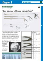
Arthrex AR-8300
Arthrex AR-8300
Arthrex AR-8300
- No tags were found...

Create successful ePaper yourself
Turn your PDF publications into a flip-book with our unique Google optimized e-Paper software.
<strong>AR</strong>-<strong>8300</strong>SAdapteur PowerSystem IIUser’s GuideThe <strong>Arthrex</strong> Adapteur Power System II User’s Guide providesimportant information for the safe operation of all componentsof the <strong>Arthrex</strong> Adapteur Power System II (Model <strong>AR</strong>-<strong>8300</strong>),including accessories. Read this User’s Guide thoroughly prior tousing this system and keep it in an easily accessible place for useby all operating personnel. Read and follow all safety warnings,cautions, and notes.U.S. PATENT PENDING0086<strong>Arthrex</strong>, Inc.Naples, FL 34108-1945 USAToll Free: 800 934-4404www.arthrex.com<strong>Arthrex</strong> Med. Inst. GmbH85757 Karlsfeld, GermanyTelephone: 49 81 31 59 57 290www.arthrex.deLM0652D© <strong>Arthrex</strong>, Inc. All rights reserved.GB
Adapteur Power System User’s GuideGBTABLE OF CONTENTSTABLE OF CONTENTS............................................................................................................................................................. 21.0 READ THIS FIRST!....................................................................................................................................................... 41.1 IMPORTANT SYMBOLS AND CONVENTIONS ................................................................................................................... 41.2 SHIPPING,UNPACKING, AND W<strong>AR</strong>RANTY INFORMATION .............................................................................................. 41.3 IMPORTANT SAFETY INFORMATION............................................................................................................................... 52.0 PRODUCT DESCRIPTION .......................................................................................................................................... 52.1 FUNCTIONAL DESCRIPTION AND INTENDED USE ........................................................................................................... 52.2 PRODUCT FEATURES...................................................................................................................................................... 62.2.1 <strong>AR</strong>-<strong>8300</strong> Console: Front Panel................................................................................................................................ 62.2.2 <strong>AR</strong>-<strong>8300</strong> Console: Rear Panel ................................................................................................................................. 72.2.3 <strong>AR</strong>-<strong>8300</strong> Console: Front Panel (With Software 5.01.00 or Higher) ........................................................................ 82.2.4 <strong>AR</strong>-<strong>8300</strong> Rear Panel: (With Software 5.01.00 or Higher) ....................................................................................... 92.2.5 <strong>AR</strong>-<strong>8300</strong> Display Messaging .................................................................................................................................. 102.2.6 Standard Footswitch .............................................................................................................................................. 112.3 TECHNICAL SPECIFICATIONS ....................................................................................................................................... 112.3.1 Console................................................................................................................................................................... 112.3.2 Standard Footswitch .............................................................................................................................................. 122.3.3 Ambient Conditions for Operation ......................................................................................................................... 122.3.4 Ambient Conditions for Storage (in shipping packaging) ...................................................................................... 123.0 SETUP............................................................................................................................................................................ 123.1 HOW TO SET UP THE CONSOLE.................................................................................................................................... 123.2 AC POWER SAFETY CONSIDERATIONS ........................................................................................................................ 123.3 HOW TO SET UP A FOOTSWITCH.................................................................................................................................. 133.4 HOW TO SET UP THE SHAVER HANDPIECES................................................................................................................. 143.5 HOW TO SET UP OTHER ACCESSORY HANDPIECES ..................................................................................................... 143.6 HOW TO ADJUST THE SYSTEM..................................................................................................................................... 143.6.1 Brightness Adjustment............................................................................................................................................ 143.6.2 Language Selection ................................................................................................................................................ 154.0 OPERATION ................................................................................................................................................................ 154.1 CONSOLE (<strong>AR</strong>-<strong>8300</strong>) SPEED ADJUSTMENT.................................................................................................................. 154.2 CONSOLE (<strong>AR</strong>-<strong>8300</strong>) OSCILLATION MODE ADJUSTMENT ........................................................................................... 164.3 ACCESSORY HANDPIECE SPEED LIMITS AND DELTAS ................................................................................................. 164.3.1 Drill Speed Table ................................................................................................................................................... 164.3.2 Front Panel Switches.............................................................................................................................................. 174.4 ATTACHMENT MOTOR CONTROL ................................................................................................................................174.4.1 Definition of Direction ........................................................................................................................................... 174.4.2 Forward, Reverse and Oscillate Modes ................................................................................................................. 174.4.3 Cruise Control........................................................................................................................................................ 174.4.4 Toggle Function ..................................................................................................................................................... 184.5 FOOTSWITCHES ........................................................................................................................................................... 194.5.1 Standard Footswitch .............................................................................................................................................. 194.5.2 Gas Pedal Footswitch ............................................................................................................................................ 194.5.3 Multi-Function Footswitches.................................................................................................................................. 194.6 ACCESSORY HANDPIECES............................................................................................................................................ 195.0 CLEANING AND DISINFECTION ........................................................................................................................... 205.1 CONSOLE (<strong>AR</strong>-<strong>8300</strong>)................................................................................................................................................... 205.2 FOOTSWITCHES ........................................................................................................................................................... 205.3 ACCESSORY CABLE ..................................................................................................................................................... 205.4 ACCESSORY HANDPIECES............................................................................................................................................ 212
Adapteur Power System User’s Guide6.0 STERILIZATION......................................................................................................................................................... 216.1 ACCESSORY CABLE ..................................................................................................................................................... 226.2 ACCESSORY HANDPIECES............................................................................................................................................ 227.0 TRANSMISSIBLE SPONGIFORM ENCEPHALOPATHY AGENTS .................................................................. 238.0 MAINTENANCE.......................................................................................................................................................... 239.0 TROUBLESHOOTING ............................................................................................................................................... 249.1 REPLACING THE FUSES ................................................................................................................................................ 249.2 TROUBLESHOOTING INTERFERENCE TO OTHER DEVICES ............................................................................................ 2510.0 LIMITED W<strong>AR</strong>RANTY.............................................................................................................................................. 2511.0 REPAIR POLICY......................................................................................................................................................... 2612.0 ELECTROMAGNETIC EMISSIONS........................................................................................................................ 2613.0 CONTACT INFORMATION ...................................................................................................................................... 2813.1 COMPLIANCE INFORMATION........................................................................................................................................ 28GBLIST OF FIGURESFIGURE 1 FRONT PANEL OF CONSOLE....................................................................................................................................... 6FIGURE 2 RE<strong>AR</strong> PANEL OF CONSOLE......................................................................................................................................... 7FIGURE 3 FRONT PANEL OF CONSOLE (WITH SOFTW<strong>AR</strong>E 5.01.00 OR HIGHER............................................................................ 8FIGURE 4 RE<strong>AR</strong> PANEL OF CONSOLE (WITH SOFTW<strong>AR</strong>E 5.01.00 OR HIGHER)........................................................................... 9FIGURE 5 STAND<strong>AR</strong>D FOOTSWITCH......................................................................................................................................... 11FIGURE 6 LAYOUT OF THE <strong>AR</strong>-<strong>8300</strong> DISPLAY........................................................................................................................ 15LIST OF TABLESTABLE 1 FRONT PANEL ELEMENTS.......................................................................................................................................... 6TABLE 2 RE<strong>AR</strong> PANEL ELEMENTS............................................................................................................................................ 7TABLE 3 FRONT PANEL ELEMENTS.......................................................................................................................................... 8TABLE 4 RE<strong>AR</strong> PANEL ELEMENTS............................................................................................................................................ 9TABLE 5 <strong>AR</strong>-<strong>8300</strong> DISPLAY MESSAGING............................................................................................................................... 10TABLE 6 ELEMENTS OF THE STAND<strong>AR</strong>D FOOTSWITCH ........................................................................................................... 11TABLE 7 <strong>AR</strong>-<strong>8300</strong> CONSOLE SPECIFICATIONS....................................................................................................................... 11TABLE 8 STAND<strong>AR</strong>D FOOTSWITCH SPECIFICATIONS .............................................................................................................. 12TABLE 9 <strong>AR</strong>-<strong>8300</strong>S AMBIENT CONDITIONS FOR OPERATION ............................................................................................... 12TABLE 10 <strong>AR</strong>-<strong>8300</strong>S AMBIENT CONDITIONS FOR STORAGE................................................................................................... 12TABLE 11 ACCESSORY HANDPIECE SPEED LIMITS AND DELTA .............................................................................................. 16TABLE 12 TROUBLESHOOTING:FAULTS AND THEIR CAUSES AND REMEDIES......................................................................... 24TABLE 13 GUIDANCE AND MANUFACTURER'S DECL<strong>AR</strong>ATION - ELECTROMAGNETIC EMISSIONS............................................... 26TABLE 14 GUIDANCE AND MANUFACTURER'S DECL<strong>AR</strong>ATION - ELECTROMAGNETIC IMMUNITY ............................................... 26TABLE 15 GUIDANCE AND MANUFACTURER'S DECL<strong>AR</strong>ATION - ELECTROMAGNETIC IMMUNITY ............................................... 273
Adapteur Power System User’s Guide1.0 Read This First!1.1 Important Symbols and ConventionsThe Adapteur Power System II User’s Guide identifies critical, important, and usefulinformation using these symbols and conventions. Your familiarity with thesesymbols and conventions is required.GBW A R N I N G !The W<strong>AR</strong>NING! symbol identifies critical information that must be followedprecisely to avoid injury or death. The W<strong>AR</strong>NING! symbol is the mostimportant safety symbol.The CAUTION! symbol identifies important methods and procedures that must befollowed to avoid damaging the device or causing it to malfunction.NOTE:This symbol identifies useful information that can simplify the setup and operationof this device.1.2 Shipping, Unpacking, and Warranty InformationPrior to use in a surgical procedure, carefully unpack and inspect the components forany sign of damage that may have occurred during shipping. If shipping damage issuspected, notify <strong>Arthrex</strong> or any authorized <strong>Arthrex</strong> distributor immediately. Anysuch damage could compromise patient safety.If transport or first-installation damage is not reported within seven business days ofreceiving the device, the warranty could be rendered void.Refer also to our General Terms of Business.<strong>Arthrex</strong> assumes a warranty to the first purchaser for a twelve month period withregard to defects or failure of its medical devices. All defective products covered bythe warranty are repaired or replaced free of charge by <strong>Arthrex</strong> at <strong>Arthrex</strong>'s discretion.The warranty does not cover any damage caused by unlawful use or improperhandling of a particular product.The warranty becomes invalid when <strong>Arthrex</strong> products are changed in any way orrepairs are performed by any party other than <strong>Arthrex</strong>.<strong>Arthrex</strong> will answer any questions referring to the quality, reliability, and/or shelf lifeof any product identified in this User’s Guide.4
Adapteur Power System User’s Guide1.3 Important Safety InformationW A R N I N G !This device is to be used by or under the supervision of a trained and licensed physician.This device should not be used by untrained personnel or used for indications other thanthose described in this User’s Guide.U.S. Federal Law restricts this device to use only by or on order of a physician.DO NOT—under any conditions or for any reason—open the console (<strong>AR</strong>-<strong>8300</strong>)or any other shaver accessory.NOTE: Read this User’s Guide thoroughly before attempting to operate the device and retain forfuture reference.Users of this device are encouraged to contact their <strong>Arthrex</strong> representatives if, in theirprofessional judgment, they require a more comprehensive surgical technique.2.0 Product DescriptionGB2.1 Functional Description and Intended UseThe <strong>Arthrex</strong> Adapteur Power System II is a multi-functional system designed formany different orthopedic uses.The system is microprocessor controlled and can operate several different handpieces.Handpieces are connected to the console by means of a cable and are operated by awaterproof footswitch or by the front panel switches.The <strong>AR</strong>-<strong>8300</strong> console is designed for continuous operation. The motorized handpiecesare individually protected by a resetting thermal fuse. In the event of a motoroverload fault (e.g., excess current) the fuse heats up and the device is de-activated.When the fault is removed and the thermal fuse cools down (typically about 30seconds) operation resumes, retaining the pre-failure settings.The cable and all handpieces can be sterilized. This means that the handpieces can bechanged during the surgical procedure without endangering surgical sterility.The Adapteur Power System <strong>AR</strong>-<strong>8300</strong>S includes:• <strong>AR</strong>-<strong>8300</strong>, Console with power cord• Standard Footswitch• Two Shaver Handpieces• User’s GuideOptional Accessories:• Gas Pedal Footswitch• Corded Multi-Function Footswitch5
Adapteur Power System User’s Guide• Wireless Multi-Function Footswitch• Accessory Handpiece Cable• Drill Handpiece with key for Jacobs chuck• Sagittal Saw Handpiece with wrenchSave the packaging for later transport of the device.GBW A R N I N G !This device is to be used by or only under the supervision of a trained and licensedphysician. This device should not be used by untrained personnel or used for indicationsother than those described in this User’s Guide.2.2 Product Features2.2.1 <strong>AR</strong>-<strong>8300</strong> Console: Front PanelFigure 1 shows the front panel of the <strong>AR</strong>-<strong>8300</strong> console. Features and symbols areidentified in Table 1.FIGURE 1FRONT PANEL OF CONSOLE5 78 9 10 11 13ABC D E FGHTABLE 1FRONT PANEL ELEMENTSFEATURESSYMBOLS1 Handpiece 1 SpeedA Protection plate TYPE BFIncrease/Decrease switches2 Handpiece 1 Operator Display B Handpiece 1 ID Label3 Handpiece 1 Handpiece Receptacle C Handpiece 1 Speed Adjust4 Handpiece 1 REVERSE Switch D Handpiece 1 Receptacle5 Handpiece 1 OSCILLATE Switch E Handpiece 1 Classification6 Handpiece 1 Footswitch Receptacle F Handpiece 1 Direction Adjust7 Handpiece 1 FORW<strong>AR</strong>D Switch G Footswitch 1 Receptacle8 Handpiece 2 SpeedH Footswitch 1 ClassificationIncrease/Decrease switches9 Handpiece 2 Operator Display I Handpiece 2 ID Label10 Handpiece 2 Handpiece Receptacle J Handpiece 2 Speed Adjust11 Handpiece 2 REVERSE Switch K Handpiece 2 Receptacle6
Adapteur Power System User’s GuideFEATURES SYMBOLS12 Handpiece 2 OSCILLATE Switch L Handpiece 2 Classification13 Handpiece 2 Footswitch Receptacle M Handpiece 2 Direction Adjust14 Handpiece 2 FORW<strong>AR</strong>D Switch N Footswitch 2 Receptacle15 AC Mains POWER switch O Footswitch 2 Classification2.2.2 <strong>AR</strong>-<strong>8300</strong> Console: Rear PanelFigure 2 shows the rear panel of the console. Features and symbols are identified inTable 2.FIGURE 2RE<strong>AR</strong> PANEL OF CONSOLEGBTABLE 2RE<strong>AR</strong> PANEL ELEMENTSELEMENTNUMBERELEMENT NAME1 Main Power Input Plug2 Comply with Operating Instructions Symbol3 Model Number4 Fan5 Splash Proof Symbol6 Serial Number Label7 Address8 Equipotential Bonding Pin9 Equipotential Bonding Symbol10 Fuse holder for the Power Entry Module7
Adapteur Power System User’s Guide2.2.3 <strong>AR</strong>-<strong>8300</strong> Console: Front Panel (With Software 5.01.00 or Higher)Figure3 shows the front panel of the <strong>AR</strong>-<strong>8300</strong> console. Features and symbols areidentified in Table 3.FIGURE 3FRONT PANEL OF CONSOLE (WITH SOFTW<strong>AR</strong>E 5.01.00 OR HIGHERGBTABLE 3FRONT PANEL ELEMENTSFEATURESSYMBOLS1 Handpiece 1 SpeedA Handpiece 1 ReceptacleIncrease/Decrease switches2 Handpiece 1 Operator Display B Footswitch 1 Receptacle3 Handpiece 1 Handpiece Receptacle C Handpiece 2 Receptacle4 Handpiece 1 REVERSE Switch D Footswitch 2 Receptacle5 Handpiece 1 OSCILLATE Switch6 Handpiece 1 Footswitch Receptacle7 Handpiece 1 FORW<strong>AR</strong>D Switch8 Handpiece 2 SpeedIncrease/Decrease switches9 Handpiece 2 Operator Display10 Handpiece 2 Handpiece Receptacle11 Handpiece 2 REVERSE Switch12 Handpiece 2 OSCILLATE Switch13 Handpiece 2 Footswitch Receptacle14 Handpiece 2 FORW<strong>AR</strong>D Switch15 AC Mains POWER switch8
Adapteur Power System User’s Guide2.2.4 <strong>AR</strong>-<strong>8300</strong> Rear Panel: (With Software 5.01.00 or Higher)Figure 4 shows the rear panel of the console. Features and symbols are identified inTable 4.FIGURE 4RE<strong>AR</strong> PANEL OF CONSOLE (WITH SOFTW<strong>AR</strong>E 5.01.00 OR HIGHER)GBTABLE 4RE<strong>AR</strong> PANEL ELEMENTSELEMENT ELEMENT NAMENUMBER1 Main Power Input Plug2 Comply with Operating Instructions Symbol3 Model Number4 Fan5 Protection Plate Type BF6 Splash Proof Symbol7 Serial Number Label8 Address9 Equipotential Bonding Pin10 Equipotential Bonding Symbol11 Fuse holder for the Power Entry Module9
Adapteur Power System User’s Guide2.2.5 <strong>AR</strong>-<strong>8300</strong> Display MessagingA listing of informational and error messages is shown in Table 5GBTABLE 5MESSAGE<strong>Arthrex</strong>APSIIINACTIVEDFSGFSSFSNo ToolShaverDrillSag SawSJ Shaverrpm**EEPROM Reset****Motor Fault****Overload****Self Test Fail***CRUISE NOTALLOWED**FWD or REV ONLY**Lock**TOGGLE NOTALLOWED*AggCC ONEffEnglishF/RFrenchFwdFwd>Gas Pedal FootswitchGermanItalianNo FootswitchOscOsc~Prog Mode:BRIGHTNESSProg Mode:LANGUAGERev key changes modeRevRevSpanishStandard FootswitchStdUse Speed Increase- to set<strong>AR</strong>-<strong>8300</strong> DISPLAY MESSAGINGEXPLANATIONPower on message, Handpiece 1 displayPower on message, Handpiece 2 displayHandpiece disabledDigital Footswitch ConnectedGas Pedal Footswitch ConnectedStandard Footswitch ConnectedNo tool connected on channelShaver connectedDrill connectedSagittal Saw connectedShaver connectedSpeed designation, revolutions per minuteMomentarily displayed first time microcontroller is programmed, or if internal memoryhas faulted and is reset.Momentarily displayed when motor fault condition occursMomentarily displayed when motor over-current condition occursConsole has failed a critical power on testMomentarily displayed when cruise button pressed with tool that doesn’t allow cruisecontrolMomentarily displayed for tools that do not support OSC modeSpeed locked on cruise controlMomentarily displayed when toggle button pressed with two footswitches connected, orno tool on opposite channel.Current mode: Aggressive oscillation mode (stopped)Cruise control enabled, about to lockCurrent mode: Efficient oscillation mode (stopped)Programming mode. Language set to EnglishCurrent mode: forward/reverse (stopped)Programming mode. Language set to FrenchCurrent mode: Forward (stopped)Current status: Motor is moving forwardMomentarily displayed when gas pedal footswitch connectedProgramming mode. Language set to GermanProgramming mode. Language set to ItalianMomentarily displayed when footswitch disconnectedCurrent mode: oscillation (stopped)Current status: Motor is oscillatingConsole is in programming mode. Set the display brightnessConsole is in programming mode. Set the languageProgramming mode instructions to change function (currently LANGUAGE orBRIGHTNESS)Current mode: Reverse (stopped)Current status: Motor is moving in reverseCurrent status: Motor is running (for saw)Programming mode. Language set to SpanishMomentarily displayed when standard footswitch connectedCurrent mode: Standard oscillation mode (stopped)Programming mode instructions to change parameter10
Adapteur Power System User’s Guide2.2.6 Standard FootswitchFigure 5 shows the Standard Footswitch. Features and symbols are identified inTable 6.FIGURE 5STAND<strong>AR</strong>D FOOTSWITCHGBTABLE 6ELEMENTS OF THE STAND<strong>AR</strong>D FOOTSWITCHELEMENT ELEMENT NAMENUMBER1 Cable2 Speed Increase Button3 Toggle Button4 Forward Pedal5 Oscillating Pedal6 Reverse Pedal2.3 Technical Specifications2.3.1 ConsoleTABLE 7<strong>AR</strong>-<strong>8300</strong> CONSOLE SPECIFICATIONSWidthHeightDepthWeightWater protectionMains cablePower entrymoduleFuse valueAC inputCleaning, disinfection,and sterilization36.8 cm (14.5 inches)13.2 cm (5.2 inches)32.5 cm (12.8 inches)7.2 kg (16 lbs.)IPX110 A/250 VIEC 320/C136.3 Amp, 250 VAC, 2.0 cm (0.75 inches)87-264 VAC, 47-63 HzRefer to Sections 5.0 and 6.0.11
Adapteur Power System User’s Guide2.3.2 Standard FootswitchTABLE 8STAND<strong>AR</strong>D FOOTSWITCH SPECIFICATIONSGBFunctionsWidthHeightDepthWeightWater protectionCleaning, disinfection,and sterilization2.3.3 Ambient Conditions for OperationTABLE 9Reverse, Forward, Oscillate, Speed Increase, and Toggle23.6 cm (9.3 inches)2.5 cm (1.0 inches)20.8 cm (8.2 inches)2.2 kg (5 lbs.)IPX8Refer to Sections 5.0 and 6.0<strong>AR</strong>-<strong>8300</strong>S AMBIENT CONDITIONS FOR OPERATIONTemperature 10° to 40°C (50° to 104°F)Relative humidity 30% to 75%Air pressure 700 hPa to 1060 hPa (21 in. Hg to 31.3 in. Hg)2.3.4 Ambient Conditions for Storage (in shipping packaging)3.0 SetupTABLE 10<strong>AR</strong>-<strong>8300</strong>S AMBIENT CONDITIONS FOR STORAGETemperature -40° to 70°C (-40° to 158°F)Relative humidity 0% to 100%, non-condensingAir pressure 500 hPa to 1160 hPa (15 in. Hg to 31.3 in. Hg)3.1 How to Set Up the ConsoleUsers of this device are encouraged to contact their <strong>Arthrex</strong> representatives if, in theirprofessional judgment, they require a more comprehensive surgical technique.3.2 AC Power Safety ConsiderationsThe <strong>AR</strong>-<strong>8300</strong> is powered by a medically rated universal AC input switching powersupply, which allows the console to be connected to any local AC mains outletprovided that you use the appropriate plug and a reliable ground conductor.Two power cords are supplied by default with the <strong>AR</strong>-<strong>8300</strong>: one for the electricalstandards of the U.S. and one for the electrical standards of Germany. Contact your<strong>Arthrex</strong> representative if you need a power cord that must meet the electricalstandards of another country.The console has been designed to meet power-saving guidelines. The console has anAC mains switch on the front panel. When the AC mains switch is OFF, no electricalpower is drawn by the console.When the AC mains switch is ON, the console automatically executes a brief series ofself-diagnostic tests. Upon successful completion of these self-diagnostic tests, theconsole displays the name and model number. If the tests discover a problem, you see12
Adapteur Power System User’s Guidethe problem displayed in the display. Refer to Table 5 for a listing of <strong>AR</strong>-<strong>8300</strong> DisplayMessaging.In the event of an AC power interruption, the console can run continuously without afault for up to 10 milliseconds. If AC power failure lasts for longer than 10milliseconds, the system will return to default settings when AC power is restored.W A R N I N G !TIf high-frequency devices are in use, or defibrillation of the patient is required, ensurethat the device is not in direct contact with the patient.TThis device has passed testing for EMI / RFI radiation and susceptibility andEMC compatibility. However, if not set up and used in accordance with theinstructions provided by <strong>Arthrex</strong>, this device may cause interference to otherdevices in the near vicinity.GBW A R N I N G !DO NOT stack or place equipment adjacent to the <strong>AR</strong>-<strong>8300</strong> console if possible. If such aconfiguration is necessary, carefully observe the configuration in question to ensure thatelectromagnetic interference does not degrade performance.W A R N I N G !TUse only <strong>Arthrex</strong>-approved accessories. Other accessories may result in increasedemissions or decreased immunity of the system. Contact your <strong>Arthrex</strong> representative fora complete list of accessories. DO NOT modify any accessory. Failure to comply willresult in patient and/or operating room staff injury.3.3 How to Set Up a FootswitchOnly use footswitches that have been developed by <strong>Arthrex</strong> specifically for the<strong>AR</strong>-<strong>8300</strong> Adapteur Power System II.NOTE: Setup for a footswitch is the same for all models. The console will detect which version is attachedand allow functions as appropriate.Insert the 15-pin connector from the footswitch into the footswitch receptacle of theconsole so that the red dots on the connector and receptacle align and they engageeasily.13
Adapteur Power System User’s Guide3.4 How to Set Up the Shaver HandpiecesOnly use shaver handpieces and cables that have been developed by <strong>Arthrex</strong>specifically for the Adapteur Power System II.Insert the 15-pin connector from the handpiece into the handpiece receptacle of theconsole so that the red dots on the connector and receptacle align and engage easily.GB3.5 How to Set Up Other Accessory HandpiecesOnly use handpieces and cables that have been developed by <strong>Arthrex</strong> specificallyfor the Adapteur Power System II.Other accessory handpieces are available for use with the Adapteur Power System IIand may require the use of an accessory cable. Specific instructions for use of aparticular accessory handpiece are packaged with the handpiece. The procedure forsetting up the handpiece and accessory cable is described below.Insert one end of the accessory cable connector (13-pin) into the cable receptacle of theaccessory handpiece so that the red dots on the connector and receptacle align andengage easily.Connect the other end of the accessory cable to the handpiece receptacle of the consoleso that the red dots on the connector and receptacle align and engage easily.3.6 How to Adjust the SystemDo not attach handpiece(s) or footswitch(s) during Self Test or during thefollowing Programming Modes.3.6.1 Brightness AdjustmentThis display allows the operator to vary the display brightness by using theFORW<strong>AR</strong>D and REVERSE switches. These switches increment or decrement thebrightness and cycle around from the minimum to the maximum setting.1. Press and hold the Handpiece 2 FORW<strong>AR</strong>D and REVERSE Switches duringpower up.2. Depress the Handpiece 1 Speed Increase or Speed Decrease Switches toincrease/decrease brightness setting respectively.3. Once desired brightness is reached, depress the Handpiece 1 Reverse switchtwice and system is ready for use.14
Adapteur Power System User’s Guide3.6.2 Language Selection4.0 OperationThis display allows the user to select one of five languages. The language is selectedby using the FORW<strong>AR</strong>D and REVERSE switches. The switches will scroll throughthe selected choices and wrap around at the beginning and end of the list.You can view the display text in English, French, German, Italian, or Spanish. Thedefault language is English. To select a different language, follow these steps.NOTE: Reference Figure 1 or Figure 3 for a diagram of front panel. Do not switch the unit off ordisconnect the main power plug, until final step is finished, otherwise all changed settings are lost.1. Depress the Handpiece 2 FORW<strong>AR</strong>D and REVERSE switches during powerup.2. Depress the Handpiece 1 Reverse switch once to enable Language selection.3. Depress the Handpiece 1 Speed Increase or Speed Decrease switches to selectthe desired Language.4. Once you choose the Language, depress the Handpiece 1 Reverse switch. Thesystem is ready for use.GB4.1 Console (<strong>AR</strong>-<strong>8300</strong>) Speed AdjustmentTo power on the console, toggle the "POWER SWITCH" button to the ON position.The console initiates a series of self-diagnostic checks.Figure 6 shows the layout for the two independent displays: one display for eachattachment channel. The two displays operate exactly the same for their respectivechannel.FIGURE 6LAYOUT OF THE <strong>AR</strong>-<strong>8300</strong> DISPLAYTool NameChannel Inactiveor Pedal Type Tool NameChannel Inactiveor Pedal TypeHANDPIECE 1 HANDPIECE 2S a g S a w I N A C T I V E S h a v e r G F S1 8 0 0 0 R P M F / R 8 0 0 0 R P M F WD > * L O C K *SpeedMode orMotorStatusCruiseControlStatusSpeedMode orMotorStatusCruiseControlStatusThe top line is split into two areas. The left side displays the name of the device, andthe right side displays either the footswitch attached (or blank if no footswitch), or“INACTIVE” if the channel is disabled (see Section 4.3.4, “Toggle Function”).The bottom line is divided into three areas:1. Speed, which reflects the RPM of the output shaft for the device attached15
Adapteur Power System User’s Guide2. When the motor is stopped, the mode is Forward (FWD) or Reverse (REV) orthe current Oscillate Mode (STD, EFF or AGG), as described in section 4.2.When the motor is running, the direction is: Forward (FWD), Reverse (REV) orOscillating (OSC).3. Cruise Control Status: *Lock* or Cruise Control ON (CC ON)The bottom line is also used to display momentary status or error messages.GB4.2 Console (<strong>AR</strong>-<strong>8300</strong>) Oscillation Mode AdjustmentThe <strong>AR</strong>-<strong>8300</strong> console with Revision 5.00.00 or higher software has three differentoscillation modes: Standard (STD), Efficient (EFF) and Aggressive (AGG). The currentmode will be shown in the bottom line of the display as either STD, EFF or AGG whenthe <strong>AR</strong>-<strong>8300</strong> console is powered up and an accessory shaver handpiece is installed.To change oscillation modes:1. Press and hold ‘speed up’ and ‘speed down’ buttons for 3 seconds.2. When the program menu appears, press ‘speed up’ to change the mode.a. The menu display will cycle between the three modes from Standard toEfficient to Aggressive then back to Standard.3. Once the desired oscillation mode is displayed, press ‘speed down’ to save theselected mode and exit the program menu.4.3 Accessory Handpiece Speed Limits and DeltasThe console supports unique accessory handpiece motor-speed limits, defaults, andspeed increment/decrement “deltas”. These are defined below for the supportedhandpieces.TABLE 11ACCESSORY HANDPIECE SPEED LIMITS AND DELTAHandpieceForward / Reverse Speeds(RPM)OscillationSpeeds(RPM)Min Max SpeedDeltaMin Max SpeedDeltaShaver 500 8000 500 500 3000 250DrillSee100 1400 Section N/A N/A N/A4.3.1.1Sag Saw 18000 18000 N/A N/A N/A N/A4.3.1 Drill Speed TableThe drill is an exception to the regular increments in speed that the other attachmentscycle through. The drill supports these speeds only: 100, 300, 500, 900, and 1400(RPM).NOTE: While operating handpieces, settings can be changed without risk of damaging the motor orconsole.16
Adapteur Power System User’s GuideW A R N I N G !If defibrillation of the patient is required or the surgical process entails working withhigh frequency instruments, ensure that the patient is not in direct contact with theequipment.4.3.2 Front Panel SwitchesThe Speed Increase and Speed Decrease panel switches adjust the speed. Each timethe switch is actuated the speed is adjusted as shown in Table 11. If multiple switchesare pressed simultaneously, the switch commands are ignored.If the Speed Increase or Speed Decrease switches are continuously actuated for morethan 1.0 seconds then the speed will auto-increment or decrement accordingly. Thevalues will not exceed the minimum and maximum values defined for the attachment.GB4.4 Attachment Motor Control4.4.1 Definition of DirectionThe definition of direction as viewed looking from the proximal to the distal of theshaver handpiece:I - Reverse Counterclockwise (CCW)II - Forward Clockwise (CW)III - Oscillate CW then CCWIV - Stop No rotation4.4.2 Forward, Reverse and Oscillate ModesReverse, Forward, and Oscillate buttons/pedals select which direction the motorrotates. If the Reverse and Forward buttons/pedals are detected simultaneously thenthe motor defaults to oscillation mode. The motor will rotate in a forward directionfirst when oscillation is entered. If any other combination of button/pedal activationsis detected simultaneously, then the commands are ignored. This operation applies tothe console front-panel buttons as well as to the supported footswitch pedals.4.4.3 Cruise ControlThe cruise control function is engaged from the Gas Pedal Footswitch, which isavailable as an optional system accessory. Cruise control operation is as follows:1. CRUISE SET - When you select the Cruise Control Switch, the Cruise functionbecomes <strong>AR</strong>MED (signified by a single audible 1 second alarm/beep) but theLOCK IN period does not start until one of the three pedals is actuated. If apedal is not actuated within 15.0 seconds then the Cruise function becomesDIS<strong>AR</strong>MED (signified by a single audible 1 second alarm/beep). If the Cruiseswitch is actuated on an attachment that does not allow cruise control, an error17
Adapteur Power System User’s Guidealarm (beep) occurs (3 fast tones), and a momentary message is displayed“*CRUISE NOT ALLOWED*”.GB2. CRUISE LOCK - The LOCK IN period lasts for up to 15.0 seconds. During theLOCK IN period the operator adjusts the speed and must hold the pedalsteady for 3 seconds in order for the LOCKED state to occur. Steady is definedas ±500 RPM for forward/reverse, and ±400 RPM for oscillation. If the pedal isheld steady, the Shaver Console emits an audible double alarm/beep) (2 brieftones) that indicates the LOCKED state has been entered, and “*Lock*” isdisplayed. If the pedal was not held steady within the 15 second LOCK INperiod, then the Cruise function becomes DIS<strong>AR</strong>MED (signified by a singleaudible 1 second alarm (beep).3. REMOVE FOOT - The operator is allowed to move the same pedal for thenext 3 seconds without leaving the LOCKED state. This is necessary, since theact of taking the foot off of the pedal moves the pedal position. Once the pedalis fully released or 3 seconds has elapsed, whichever comes first, then thesystem again responds to this pedal and disables the Cruise function. At anytime during or after this 3 second period (i.e., during the Cruise Lock state) ifany OTHER pedal, footswitch or panel switch is activated for that channel, theCruise function becomes DIS<strong>AR</strong>MED.4. DISABLE CRUISE LOCK - If any other footswitch or front-console panelbutton is activated while in the LOCKED state, the Cruise function becomesDIS<strong>AR</strong>MED (with the exception noted in item 3 “Remove Foot”).5. DISABLE CRUISE SET - If the Toggle, Cruise Control, or Front Panel buttonsare actuated at any time after the Cruise Control button is selected (i.e. in the<strong>AR</strong>MED or LOCKED condition) then the Cruise function becomesDIS<strong>AR</strong>MED.4.4.4 Toggle FunctionThe toggle function is a button on footswitches that allows the operator to control theother handpiece without having to physically move the footswitch connection. Toggleis allowed when there is one footswitch connected and two handpieces connected.When the user presses the toggle switch and the conditions are met for a valid toggle,a long alarm (beep) indicates the footswitch has been toggled, and now the user cancontrol the opposite handpiece with the footswitch. Additionally, the originalhandpiece that the user was previously controlling becomes inactive, which means itcannot be operated from either the footswitch or front panel controls.When the user presses toggle again, the footswitch goes back to controlling theoriginal handpiece, and the opposite handpiece becomes inactive.When a toggle function occurs, the footswitch indicator moves to the display channelthat the user is controlling, and the other channel is shown as “INACTIVE”.The toggle function is not allowed if there are two footswitches installed.An error alarm (beep) occurs, and the momentary message “TOGGLE NOT18
Adapteur Power System User’s GuideALLOWED” is displayed when the user attempts to toggle with two footswitchesinstalled.The toggle function is not allowed if only one handpiece is attached. An error alarm(beep) occurs, and the momentary message “TOGGLE NOT ALLOWED” is displayedwhen the user attempts to toggle when there is only one handpiece attached to theconsole.4.5 FootswitchesThe footswitch cable connects and locks to the console to prevent accidentalseparation during use. To avoid damage, disconnect the footswitch by pulling onthe cable connector shell (plug) only.4.5.1 Standard FootswitchThe Speed Increase button adjusts the speed in the positive direction only. Each timethe switch is actuated, the speed is adjusted as shown in the Table 11. When themaximum speed is reached, the next time the switch is actuated, the speed settingcycles and returns to the minimum setting. If multiple switches are detectedsimultaneously then the switch commands are ignored.If the Speed Increase switch is continuously actuated for more than 1.0 seconds thenthe speed auto-increments accordingly. The speed setting will not wrap when autoincrementing.Release the Speed Increase button and then press it again to get thespeed setting to cycle to the minimum setting again.GB4.5.2 Gas Pedal FootswitchThe Forward, Reverse, and Oscillate pedals linearly adjust the speed. When the pedalis actuated, it returns an analog signal that is converted to a corresponding RPMbetween the minimum and maximum speed of the attachment that is connected.4.5.3 Multi-Function FootswitchesAvailable as optional accessories, both the Wireless and Corded Multi-FunctionFootswitches can operate as either a Standard Footswitch or as a Gas Pedal Footswitchas described in the preceding sections. Function selection is made by pressing thebutton on the Multi-Function Footswitch labeled “GFS/SFS’.4.6 Accessory HandpiecesThe accessory handpiece cable connects and locks to the console to preventaccidental separation during use. To avoid damage, disconnect the accessoryhandpiece by pulling on the cable connector shell (plug) only.19
Adapteur Power System User’s Guide5.0 Cleaning and Disinfection5.1 Console (<strong>AR</strong>-<strong>8300</strong>)Clean and disinfect the console with a commercially available surface disinfectant.GB5.2 FootswitchesAlways comply with the instructions issued by the manufacturer of thedisinfectant.NEVER clean the console receptacles with liquid cleaners. Remove dust, ifnecessary, with dry compressed air.Refer to Multifunction Wireless Footswitch Operator's Manual for additional cleaninginstructions.Clean the footswitch with an enzymatic cleaner without subsequent acidneutralization.Rinse the footswitch thoroughly after cleaning.After cleaning, disinfect the footswitch with a commercially available surfacedisinfectant.Thoroughly rinse the footswitch under lukewarm water.Always comply with the instructions issued by the manufacturer of thedisinfectant.5.3 Accessory CableNEVER allow the console receptacles to have any contact with liquids. Removedust or moisture, if necessary, with dry compressed air. ONLY dry connectorsshould be plugged into the console.Clean the cable with an enzymatic cleaner without subsequent acid neutralization.Rinse the cable thoroughly after cleaning.After cleaning, disinfect the cable with a commercially available surface disinfectant.Thoroughly rinse the cable under lukewarm water.See Section 6.0 for sterilization information.Always comply with the instructions issued by the manufacturer of thedisinfectant.20
Adapteur Power System User’s GuideNEVER allow the console plug pins to have any contact with liquids. Remove dustor moisture, if necessary, with dry compressed air. ONLY dry connectors may beplugged into the console.5.4 Accessory HandpiecesRemove any accessories in the device, such as shaver blades, saw blades or drill bits.Open the suction control fully, if applicable.Clean the handpiece with an enzymatic cleaner without subsequent acidneutralization.Clean the suction control connection with a cleaning brush, if applicable.Rinse the handpiece thoroughly after cleaning.Disinfect the handpiece with a commercially available disinfectant.Thoroughly rinse the handpiece under lukewarm water.See Section 6.0 for sterilization information.GBAlways comply with the instructions issued by the manufacturer of thedisinfectant.NEVER place the shaver handpiece in Cidex or other aldehyde disinfectantsolutions.6.0 SterilizationNEVER allow the console plug pins to have any contact with liquids. Remove dustor moisture, if necessary, with dry compressed air. ONLY dry connectors may beplugged into the console.Sterilization does not eliminate the need for proper cleaning and disinfection ofinstruments prior to sterilization. Sterilization capabilities, cleaning, disinfecting,handling, and storage of instrumentation are the responsibility of qualifiedfacility/user personnel.Reusable accessories that are provided non-sterile may be sterilized by one of thefollowing methods:Gravity displacement cycles:• 270°F – 275°F (134°C): exposure time 18 minutes (minimum)• 250°F (121°C): exposure time 60 minutesPrevacuum cycle:• 270°F – 275°F (134°C): 5 minutes21
Adapteur Power System User’s GuideSterilizers vary in design and performance characteristics, so cycle parameters shouldalways be verified against the sterilizer manufacturer’s instructions for the specificsterilizer and load configuration being used. It is recommended that the user performappropriate validation tests.Drying - It is recommended to use a dry-cycle of a minimum of 4 minutes.GBCooling - The device must be adequately cooled, after being removed from thesterilizer.6.1 Accessory CableAfter sterilization in the autoclave, let the cable cool down slowly. NEVER usecold water to cool the cables down, as this can damage the cable, connections, andseals.Liquid on the cable receptacle or connection of the handpiece can cause damageto the device. Before connecting the cable, ensure the receptacles are clean anddry.W A R N I N G !After autoclaving, the cable is VERY HOT. Careless handling can result in burns.6.2 Accessory HandpiecesAfter sterilization in the autoclave, let the handpieces cool down slowly. NEVERuse cold water to cool the handpieces, as this can damage the electroniccomponents and seals.Liquid on the cable connector of the handpiece can cause damage to the device.Before connecting the cable, ensure that the receptacles are clean and dry.W A R N I N G !After autoclaving, the handpieces are VERY HOT. Careless handling can result in burns.The following special instructions are to be observed when sterilizing accessoryhandpieces.Open the suction control completely to ensure proper circulation, if applicable.Open the chuck completely to ensure proper circulation, if applicable.22
Adapteur Power System User’s GuideDo not sterilize a handpiece with accessories, such as shaver blades, drill bits orsaw blades attached.7.0 Transmissible Spongiform Encephalopathy AgentsIt is outside the scope of this document to describe (in detail) the precautions thatshould be taken for Transmissible Spongiform Encephalopathy Agents.The agents for transmission of Creutzfeldt-Jakob Disease are believed to be resistant tonormal processes of disinfection and sterilization and therefore the normal processingmethods of decontamination and sterilization as described above may not beappropriate where CJD transmission is a risk.In general, the tissues that come into contact with orthopaedic surgical instrumentsare those of low TSE infectivity. However, particular precautions should be takenwhen handling instruments that have been used on known, suspected, or at riskpatients.References8.0 MaintenanceANSI/AAMI ST46: Good Hospital Practice: Steam sterilization and sterility assurance.The Adapteur Power System requires no routine maintenance. There are no operatorrepairable components and no scheduled intervals for mechanical inspection. If anysystem component malfunctions, please contact <strong>Arthrex</strong>.GB23
Adapteur Power System User’s GuideAlways use fuses with the correct values to avoid allowing overcurrent to enterthe system.NOTE: The <strong>AR</strong>-<strong>8300</strong> console incorporates a universal AC input power supply. A voltage selectionswitch is not required.9.2 Troubleshooting Interference to Other DevicesTo correct the interference, try one or more of these suggestions:• Reorient or relocate the receiving device.• Increase the separation between devices.• Connect the device into an outlet on a circuit different from that to which theother device(s) are connected.• Consult the manufacturer or field service technician for the receiving devicefor guidance.10.0 Limited WarrantyFor a period of one (1) year after delivery of the Equipment and subject to the terms hereof,<strong>Arthrex</strong> warrants the Equipment to be free from manufacturers’ defects in material andcraftsmanship under normal use and service. The Warranty does not apply to any Equipmentthat has been repaired, serviced or altered outside of the manufacturer’s or <strong>Arthrex</strong>’s facility or toEquipment that has been subjected to abuse, misuse, neglect, accident or negligence in use,storage or handling. <strong>Arthrex</strong>’s obligation, and the Customer’s sole and exclusive remedy, islimited to the replacement or repair of any Equipment which <strong>Arthrex</strong>’s examination shalldisclose, in its sole discretion, to be defective or inoperative, and will be conditioned upon<strong>Arthrex</strong>’s receiving written notice of any alleged nonconformity or defect during the applicablewarranty period and the return of defective products to <strong>Arthrex</strong>, F.O.B. <strong>Arthrex</strong>’s facility. If<strong>Arthrex</strong> determines that any product or service is not defective or that <strong>Arthrex</strong> is not liable for thedefect, the Customer will be notified; thereafter, <strong>Arthrex</strong> will repair or replace such product uponthe Customer’s written consent and at prevailing prices. <strong>Arthrex</strong> may, in its discretion, providereasonable use of loaner Equipment while repair or replacement is underway. This warrantyapplies only to the original Customer and is not transferable except at the discretion of <strong>Arthrex</strong>.Repairs and replacements made under this warranty are not warranted beyond the remainder ofthe warranty period. <strong>AR</strong>THREX’S LIABILITY SHALL BE LIMITED SOLELY, AT <strong>AR</strong>THREX’SOPTION, TO REPAIR OR REPLACEMENT OF THE GOODS OR COMPONENT P<strong>AR</strong>TS NOTMEETING THE QUALITY AND SPECIFICATIONS W<strong>AR</strong>RANTED. THERE <strong>AR</strong>E NOW<strong>AR</strong>RANTIES, IMPLIED OR STATUTORY (INCLUDING THE W<strong>AR</strong>RANTIES OFMERCHANTABILITY, FITNESS FOR A P<strong>AR</strong>TICUL<strong>AR</strong> PURPOSE OR INTENDED USE, NON-INFRINGEMENT, OR <strong>AR</strong>ISING OUT OF A COURSE OF PERFORMANCE, DEALING ORTRADE USAGE) THAT EXTEND BEYOND THIS EXPRESS W<strong>AR</strong>RANTY. IN THE EVENTTHAT APPLICABLE LAW PREVENTS THE DISCLAIMER OF ANY IMPLIED W<strong>AR</strong>RANTIES,THEN SUCH IMPLIED W<strong>AR</strong>RANTIES SHALL BE LIMITED TO THE CONTENTS ANDDURATION OF THIS EXPRESS W<strong>AR</strong>RANTY.GB25
Adapteur Power System User’s Guide11.0 Repair PolicyContact <strong>Arthrex</strong> for a Return Authorization Number and instructions prior toreturning the device.12.0 Electromagnetic EmissionsTABLE 13GUIDANCE AND MANUFACTURER'S DECL<strong>AR</strong>ATION - ELECTROMAGNETIC EMISSIONSGBThe <strong>AR</strong>-<strong>8300</strong>S Shaver System is intended for use in the electromagnetic environment specified below. The customer or the userof the <strong>AR</strong>-<strong>8300</strong>S Shaver System should assure that it is used in such an environment.Emissions test Compliance Electromagnetic environment – guidanceRF emissionsCISPR 11Group 1The <strong>AR</strong>-<strong>8300</strong>S Shaver System uses RF energy only for its internal function.Therefore, its RF emissions are very low and are not likely to cause anyinterference in nearby electronic equipment.RF emissionsCISPR 11Class AThe <strong>AR</strong>-<strong>8300</strong>S Shaver system is suitable for use in all establishments otherthan domestic and those directly connected to the public low-voltagepower supply network that supplies buildings used for domestic purposes.Harmonic emissionsIEC 61000-3-2Class AVoltage fluctuations/flicker emissionsIEC 61000-3-3CompliesTABLE 14GUIDANCE AND MANUFACTURER'S DECL<strong>AR</strong>ATION - ELECTROMAGNETIC IMMUNITYThe <strong>AR</strong>-<strong>8300</strong>S Shaver System is intended for use in the electromagnetic environment specified below. The customer or the userof the <strong>AR</strong>-<strong>8300</strong>S Shaver System should assure that it is used in such an environment.Immunity test IEC 60601 test level Compliance level Electromagnetic environment - guidanceElectrostaticdischarge (ESD)IEC 61000-4-2± 6 kV contact± 8 kV air± 6 kV contact± 8 kV airFloors should be wood, concrete or ceramic tile. Iffloors are covered with synthetic material, the relativehumidity should be at least 30%.Electrical fasttransient/burst± 2 kV for powersupply lines± 2 kV for powersupply linesMains power quality should be that of a typicalcommercial or hospital environment.IEC 61000-4-4± 1 kV for input/outputlines± 1 kV for input/outputlinesSurgeIEC 61000-4-5± 1 kV differentialmode± 2 kV common mode± 1 kV differentialmode± 2 kV common modeMains power quality should be that of a typicalcommercial or hospital environment.Voltage dips,shortinterruptions andvoltage variationson power supply95 % dip in UT)for 0.5 cycle40% UT95% Reduction (10ms)60% Reduction(100ms)Mains power quality should be that of a typicalcommercial or hospital environment. If the <strong>AR</strong>-<strong>8300</strong>SShaver System requires continued operation duringpower mains interruptions, it is recommended that the<strong>AR</strong>-<strong>8300</strong>S Shaver System be powered from an26
Adapteur Power System User’s Guideinput linesIEC 61000-4-11Power frequency(50/60 Hz)magnetic fieldIEC 61000-4-8(60 % dip in UT)for 5 cycles70% UT(30 % dip in UT)for 25 cycles95 % dip in UT)for 5 sec30% Reduction(500ms)95% Reduction (5s)uninterruptible power supply.3 A/m 3 A/m @ 50 & 60 Hz Power frequency magnetic fields should be at levelscharacteristic of a typical location in a typicalcommercial or hospital environment.Note: UT is the a.c. mains voltage prior to application of the test level.GBTABLE 15GUIDANCE AND MANUFACTURER'S DECL<strong>AR</strong>ATION - ELECTROMAGNETIC IMMUNITYThe <strong>AR</strong>-<strong>8300</strong>S Shaver System is intended for use in the electromagnetic environment specified below. The customer or the userof the <strong>AR</strong>-<strong>8300</strong>S Shaver System should assure that it is used in such an environment.Immunity test IEC 60601 test level Compliance level Electromagnetic environment - guidancePortable and mobile RF communications equipmentshould be used no closer to any part of the <strong>AR</strong>-<strong>8300</strong>SShaver System, including cables, than therecommended separation distance calculated from theequation applicable to the frequency of the transmitter.Recommended separation distanced = 1.17P 1/2Conducted RF3 Vrms3 VrmsIEC 61000-4-6Radiated RFIEC 61000-4-3150 kHz to 80 MHz3 V/m80 MHz to 2.5 GHz150 kHz to 80 MHz3 V/m80 MHz to 2.5 GHzd = 1.17P 1/280 MHz to 800 MHzd = 2.33P 1/2800 MHz to 2.5 GHzWhere P is the maximum output power rating of thetransmitter in watts (W) according to the transmittermanufacturer and d is the recommended separationdistance in meters (m)Interference may occur in the vicinity of equipmentmarked with the following symbol:27
Adapteur Power System User’s GuideGB13.0 Contact Information<strong>Arthrex</strong>, Inc.Naples, Florida 34108-1945 USATel: +1 239-643-5553Fax: +1 239-598-5534Toll-Free Technical Support: +1 888 420-9393, Monday through Friday,9:00 AM – 5:00 PM ET.Website: www.arthrex.com<strong>Arthrex</strong> Med. Inst. GmbH85757 Karlsfeld, GermanyTel: 49 81 31 59 57 0Fax: 49 81 31 59 57 63 1Website: www.arthrex.de13.1 Compliance InformationThe Adapteur Power System II (<strong>AR</strong>-<strong>8300</strong>S) is designed and tested in accordance withEN 60601-1.According to EN 60601 the console is Type BF, Class 1, IPX1 rating. Accessories areType BF, Class 1, IPX 8.According to MDD93/42/EEC, Annex IX, Rule 9 this device is classified as a Class IIadevice.28