Dresser Roots Model 5 Prover Manual - The Meter and Valve ...
Dresser Roots Model 5 Prover Manual - The Meter and Valve ...
Dresser Roots Model 5 Prover Manual - The Meter and Valve ...
- No tags were found...

Create successful ePaper yourself
Turn your PDF publications into a flip-book with our unique Google optimized e-Paper software.
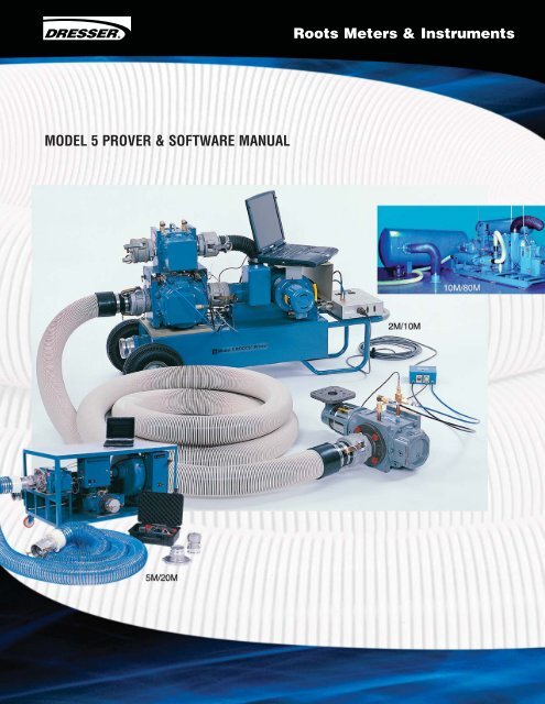
MODEL 5 PROVER & SOFTWARE MANUAL<strong>Roots</strong> <strong>Meter</strong>s & Instruments
Table of Contents1. Introduction ..................................................................................................11.1 Receiving <strong>and</strong> Inspection at time of delivery..........................................................11.2 General Information ......................................................................................11.3 Component List ............................................................................................21.4 Optional Accessories ......................................................................................51.5 <strong>The</strong>ory of Operation........................................................................................51.6 Precautions..................................................................................................51.7 Specifications (excluding Computer) ..................................................................72. Installing the <strong>Model</strong> 5 <strong>Prover</strong> Software ................................................................82.1 Minimum System Requirements ........................................................................82.2 Compatibility Issues ......................................................................................82.3 Software Installation ......................................................................................82.4 Verifying the Proper Files Are Loaded ................................................................92.5 Upgrade Notice ............................................................................................93. <strong>The</strong> Startup Screen <strong>and</strong> Help............................................................................103.1 <strong>The</strong> Startup Screen ......................................................................................103.2 <strong>The</strong> Help Directory........................................................................................104. Setting <strong>Prover</strong> Options ..................................................................................114.1 <strong>The</strong> Set <strong>Prover</strong> Options Screen ........................................................................114.2 Changing Units of Measure ............................................................................124.3 Editing Passwords ........................................................................................125. Configuring a <strong>Meter</strong> Test ................................................................................135.1 <strong>Prover</strong> Capacity ..........................................................................................135.2 Test Control Mode ........................................................................................135.3 <strong>Meter</strong> Output ..............................................................................................145.4 Drive Rate or Pulses Per Test (PPT) ..................................................................155.5 Test Volume................................................................................................165.6 Base Pressure Correction ..............................................................................165.7 Flow Rate ..................................................................................................165.8 Test Duration ..............................................................................................175.9 Selecting the Number of Test Repeats ................................................................175.10 Save, Close <strong>and</strong> Change ..............................................................................17
6. Equipment Setup ..........................................................................................186.1 Field <strong>Meter</strong> Setups ......................................................................................187. Running a <strong>Meter</strong> Test ....................................................................................247.1 Selecting a Preconfigured Test ........................................................................247.2 <strong>The</strong> Pretest Error Message Screen ....................................................................247.3 <strong>The</strong> <strong>Meter</strong> Test Screen ..................................................................................267.4 System Readouts ........................................................................................277.5 Calculated Values ........................................................................................288. Test Results <strong>and</strong> Reports ................................................................................298.1 Reviewing, Saving, <strong>and</strong> Printing Test Results ......................................................298.2 <strong>The</strong> Report Manager ....................................................................................299. Calibrating the <strong>Prover</strong> ....................................................................................319.1 Reaching the <strong>Prover</strong> Calibration Screen ..............................................................319.2 <strong>The</strong> Conversion Tool......................................................................................339.3 How to Calibrate the A/D Converter Check Point ....................................................339.4 How to Calibrate the Atmospheric Pressure Transducer ..........................................339.5 How to Calibrate the Master <strong>Meter</strong> Inlet Pressure Transducer....................................349.6 How to Calibrate the Field <strong>Meter</strong> Inlet Pressure Transducer ......................................349.7 How to Calibrate the Master <strong>Meter</strong> Temperature Probe............................................359.8 How to Calibrate the Field <strong>Meter</strong> Temperature Probe ..............................................359.9 How to Calibrate the Master <strong>Meter</strong> Outlet Pressure Transducer ..................................369.10 How to Calibrate the Field <strong>Meter</strong> Outlet Pressure Transducer ..................................3610. <strong>Prover</strong> Maintenance ....................................................................................3710.1 Master <strong>Meter</strong> Hours of Operation ....................................................................3710.2 <strong>Prover</strong> Self Test..........................................................................................3710.3 Master <strong>Meter</strong> Differential Pressure Test ............................................................3810.4 System Leak Test........................................................................................3810.5 <strong>Meter</strong> Purge ..............................................................................................4010.6 Maintenance Recommendations......................................................................4010.7 Maintenance Check List................................................................................4111. Problem Identification <strong>and</strong> Resolution ..............................................................4311.1 Common Operation Problems ........................................................................4311.2 Troubleshooting Error Messages......................................................................4411.3 Assistance & Service Procedure......................................................................4611.4 Return Authorization Procedure ......................................................................46Appendix ......................................................................................................47Spare Parts List ..............................................................................................522 Year Warranty ..............................................................................................53
1. Introduction1.1 Receiving <strong>and</strong> Inspection at time of delivery:1. Check the packing list to account for all items received.2. Inspect the shipping container for damage. Record any visible damage or shortageson the delivery record.3. File a claim with the carrier.4. Notify your ROOTS ® <strong>Prover</strong> supplier immediately.Do not accept any shipment with evidence of mish<strong>and</strong>ling without making an immediate inspection fordamage prior to signing the carrier’s delivery record. Do not attempt repairs or adjustments, as doingso may be a basis for voiding all claims for warranty or insurance claim with carrier.1.2 General Information<strong>The</strong> <strong>Model</strong> 5 ROOTS <strong>Prover</strong> is an integrated computer controlled system designed for shop or fieldproving of rotary <strong>and</strong> diaphragm-type positive displacement gas meters (80M for shop use only). <strong>The</strong><strong>Prover</strong> is designed for transfer proving utilizing air only as the test medium, <strong>and</strong> electric blowers mountedon a manifold or a skid provide the test air flow (vacuum).<strong>The</strong> <strong>Prover</strong> system consists of the following major components: Master <strong>Meter</strong>(s) as the measurementreference st<strong>and</strong>ard; pressure <strong>and</strong> temperature Transducers; Blower(s); flexible hose(s); electronic cables<strong>and</strong> accessories with a storage case; a Flow Rate Controller for automatic flow rate adjustment <strong>and</strong> testsequencing; <strong>and</strong> computer software for calculations <strong>and</strong> presentation of the flow test data. <strong>The</strong> <strong>Prover</strong> alsohas the unique capability to test ROOTS meters equipped with the Integral Micro Corrector (IMC/W2).A personal computer (not included) is required to run the software.<strong>The</strong> software program stores predetermined Field <strong>Meter</strong> test configurations. It performs all calculationsat the end of each test run <strong>and</strong> displays the pressure <strong>and</strong> temperature differentials, Field <strong>Meter</strong> proof,Field <strong>Meter</strong> accuracy, <strong>and</strong> percent error. Test reports may be saved to diskette, the PC hard drive, <strong>and</strong>/ormay be printed. You can configure the software for Imperial or Metric display <strong>and</strong> storage of data.<strong>The</strong> <strong>Model</strong> 5 10M, 2M/10M ROOTS <strong>Prover</strong> <strong>and</strong> Mobile 5M ROOTS <strong>Prover</strong> are portable units. <strong>The</strong>y may betransported into the field for on-site testing. <strong>The</strong> <strong>Prover</strong> is a precision instrument - operate <strong>and</strong> maintainit in accordance with factory recommendations as outlined in this manual to ensure accurate <strong>and</strong> repeatableresults. Transport it with care <strong>and</strong> ensure that it is properly secured <strong>and</strong> covered for protection from moisture<strong>and</strong> dirt.<strong>The</strong> blowers are not explosion proof. Do not operate them when testing in a hazardous area.Do not operate the <strong>Prover</strong> in the presence of explosive or flammable gasses or an explosion may result.<strong>The</strong> <strong>Prover</strong> system is not designed for intrinsic safety.1
1.3 Component List<strong>The</strong> following is a complete list <strong>and</strong> physicaldescription of the items available for the<strong>Model</strong> 5 ROOTS ® <strong>Prover</strong>. Your particularorder may or may not include all of thecomponents listed below. If any items thatyou ordered are missing or damaged, callthe Customer Service Department at<strong>Dresser</strong> <strong>Roots</strong> <strong>Meter</strong>s & Instruments at1-800-521-1114 or 832-590-2303.1. Black Accessory Case –A briefcase-sized, black containerused for storing <strong>Model</strong> 5 <strong>Prover</strong>accessory equipment.Figure 1: <strong>Model</strong> 5 ROOTS <strong>Prover</strong>2. <strong>Prover</strong> Software –1 Windows CD located in the lid of the black accessory case behind the foam padding.It contains the necessary software for operating the <strong>Prover</strong>.3. Computer Cable – An RS-232 capable data transmission quality cable with a15-pin connector at one end <strong>and</strong> a 9-pin connector at the other end.4. Field <strong>Meter</strong> Junction Box – A rectangular box, approximately 5 x 5 inches.Attached is a 30 ft. cable with a round 12-pin connector at one end.5. Field <strong>Meter</strong> Temperature Probe – A 6 in. long, 1/4 in. diameter silver tubewith a cable extending from it. <strong>The</strong> end of the cable has a 4-pin connector.6. <strong>Manual</strong> Start/Stop Cable <strong>and</strong> Button – A cable with a 5-pin connector at one end<strong>and</strong> a push button at the opposite end.7. 25’ Power Cord8. Pressure Lines – 1/4 in. diameter nylon tubing with compression nuts attached to each end.<strong>The</strong>re are four pressure lines - blue for Input, black for Output. One pair of blue <strong>and</strong> black linesis for the Master <strong>Meter</strong>(s) <strong>and</strong> the other is for the field or test meter.9. P&T (Pressure <strong>and</strong> Temperature) Adapter – A brass “T” assembly with a 1/4” NPTthreaded end, a compression fitting for the temperature probe <strong>and</strong> a Quick Disconnect forthe Pressure fitting.10. Field <strong>Meter</strong> Pressure Adapter – An “L” shaped brass pipe fitting with a 1/4” NPT threadedend <strong>and</strong> Quick Disconnect end that serves as a pressure-dampening device.11. Instrument Drive (ID) Pulser – A small, aluminum, rectangular box with two 90 degreeangled metal feet protruding from the underside, <strong>and</strong> an L-shaped shaft that extends downbetween the two metal feet. Included with the ID Pulser are two mounting clamps.12 ID Pulser Cable – A cable with a 5-pin connector at either end.13. Exp<strong>and</strong>able Hole Plug – A device used to seal off unused openings in the Blower manifolddepending on options ordered.14. Cam Lock Cap – A cam type cap to close off inlet of unused meter(s).15. Hose Plug – A cam type plug to seal hose end.16. <strong>Prover</strong> Hose – A flexible, ribbed hose with quick disconnects at each end.17. Personal Computer (not included) – A laptop is required for operation of <strong>Prover</strong>.See Minimum Requirements on page 8 for necessary specifications.2 ROOTS ® <strong>Model</strong> 5 <strong>Prover</strong> Software <strong>Manual</strong>
Inside Accessory Case(All <strong>Prover</strong>s)10M or 2M/10MCam Lock CapMaster <strong>Meter</strong>J BoxesMaster <strong>Meter</strong>(s)M/M CablePersonal ComputerThrottle <strong>Valve</strong>Blower(s)ControllerAccessory Case<strong>Prover</strong> HosePersonal ComputerControllerMaster <strong>Meter</strong>(s)BlowerAccessoryCase<strong>Prover</strong> Hose5M/20M3
Master <strong>Meter</strong>Junction Box(s)ControllerBlower10M/80M<strong>Prover</strong> HosesMaster <strong>Meter</strong>(s)ControllerThrottle <strong>Valve</strong>Master <strong>Meter</strong>Master <strong>Meter</strong>Junction BoxMobile 54 ROOTS ® <strong>Model</strong> 5 <strong>Prover</strong> Software <strong>Manual</strong>
18. Controller – An aluminum or steel rectangular box with a 6 in. finned heat sink on the sideof the box <strong>and</strong> a number of sockets for electrical <strong>and</strong> computer connections.19. Blowers -– Devices attached to the <strong>Prover</strong> cart, responsible for producing a source ofairflow during <strong>Prover</strong> testing.20. Master <strong>Meter</strong>(s) – <strong>The</strong> reference meter (tertiary st<strong>and</strong>ard) with known performancecharacteristics that is traceable to national <strong>and</strong> international st<strong>and</strong>ards. <strong>The</strong> <strong>Prover</strong> may bepurchased with one or two Master <strong>Meter</strong>s.21. Master <strong>Meter</strong> Cable – A cable containing a 6-pin connector at each end.22. Master <strong>Meter</strong> Junction Box – A rectangular box mounted to the end cover of theMaster <strong>Meter</strong>(s).23. Throttle <strong>Valve</strong> – An electrical actuator used to aid in the flow rate control for the prover.1.4 Optional Accessories:• Optical Scanner• ROOTS 8C <strong>Meter</strong> Test Hardware Assembly• ROOTS Series B3 Field CTR Pulser (MTR must be “Pulser Ready”)• Acoustic Filter• Inverter• 3" Quick-disconnect Connector (Female)• 3" Quick-disconnect Connector (Male)• SmartProve Cable• USB Serial Port Converter Kit1.5 <strong>The</strong>ory of Operation<strong>The</strong> <strong>Prover</strong> operates as a transfer test. <strong>The</strong> meter under test (Field <strong>Meter</strong>) registers volume <strong>and</strong> comparesit to the volume registered by a Master <strong>Meter</strong>. Blowers are used to pull a vacuum, which draws ambientair into the Field <strong>Meter</strong> <strong>and</strong> through a connecting hose directly into the Master <strong>Meter</strong>.In the normal test set-up, the mass of air passes through the meter under test <strong>and</strong> then through the Master<strong>Meter</strong>. Since the Master <strong>Meter</strong>’s characteristics are known, the meter under test can be characterized basedon the difference in its performance parameters as compared to the Master <strong>Meter</strong>. This difference inperformance is expressed in terms of accuracy (proof <strong>and</strong> percent error are also displayed).1.6 Precautions• No copies of this disk or any of the information contained there on shall be usedfor any purpose other than to operate the <strong>Model</strong> 5 ROOTS <strong>Prover</strong>.• Do not operate the <strong>Model</strong> 5 ROOTS <strong>Prover</strong> in the presence of flammable gas oran explosion may result.• Do not operate the <strong>Model</strong> 5 ROOTS <strong>Prover</strong> in the rain or while st<strong>and</strong>ing in waterin order to avoid a potential electrical shock.• Check upstream <strong>and</strong> downstream blocking or bypass valves to ensure that they operateproperly <strong>and</strong> are leak tight in the closed position before powering any device.5
• CAUTION: Purge all Field <strong>Meter</strong>s (Conventional <strong>Meter</strong> Proving) of gas prior to testing.At NO time should power be applied when the <strong>Prover</strong> is in a possibly explosive atmosphere.Observe all company safety rules, regulations, <strong>and</strong> procedures.• If the ROOTS <strong>Model</strong> 5 <strong>Prover</strong> is equipped with both the 2M <strong>and</strong> 10M or the 5M <strong>and</strong> 20MMaster <strong>Meter</strong>s, make certain that the unused Master <strong>Meter</strong> has the inlet quick-disconnectnipple capped or plugged to prevent any possibility of overspeeding the unused Master <strong>Meter</strong>.• (10M/80M ROOTS <strong>Model</strong> 5 <strong>Prover</strong> only) Never connect the 10M Master <strong>Meter</strong> directlyto the female quick-disconnect coupling of the 10M Blower Manifold when the 80M Master<strong>Meter</strong> is being used.• <strong>The</strong> majority of commercial computers/laptops are designed for an office environment.Refer to your computer's reference manual for specific operating information <strong>and</strong>specifications. Refer to the Care/Proper H<strong>and</strong>ling of Diskettes or CDs in the Help Directory.• When entering Drive Rate <strong>and</strong> Test Volume during the configuration of a <strong>Meter</strong> Test, you mustenter proper values. If the correct Drive Rate is selected from the screen, only valid TestVolumes are displayed. If "Other" is selected in either the drive rate/pulses/test, or thetest volume selections, it is up to you to enter the proper values.• (All <strong>Prover</strong>s except 10M & 2M/10M). If “Restart” is pressed during a test, the <strong>Prover</strong> may restartthe main blower with the main valve partially open. If this occurs, a sudden surge of air mayapply undue stress to both the Master <strong>and</strong> Field <strong>Meter</strong>s. Press “Stop” first. Stop the test <strong>and</strong>allow the main valve to close fully before pressing “Restart.”• When testing ROOTS intermittently integrated Temperature Compensated (TC) <strong>Meter</strong>s, makecertain to double the st<strong>and</strong>ard Pulses/Test value. This is due to the requirement of the specialroutines for testing ROOTS <strong>Meter</strong>s to count transitions instead of pulses. One up <strong>and</strong> onedown transition equal one pulse.• Controlled software should only be used with the 20M.6 ROOTS ® <strong>Model</strong> 5 <strong>Prover</strong> Software <strong>Manual</strong>
1.7 Specifications (excluding Computer)Mobile 5 2M/10M 5M/20M 10M/80MSystem Accuracy(excluding meter under test) +/- 0.55% +/- 0.55% +/- 0.55% +/- 0.55%System Repeatability(excluding meter under test) +/- 0.15% +/- 0.15% +/- 0.15% +/- 0.15%Ambient Operating Temp.Master <strong>Meter</strong> +32° to +140°F +32° to +140°F +32° to +140°F +32° to +140°F0° to +60°C 0° to +60°C 0° to +60°C 0° to +60°CController, etc -4° to +140°F -4° to +140°F -4° to +140°F -4° to +140°F-20° to +60°C -20° to +60°C -20° to +60°C -20° to +60°CAmbient Storage Temp.Master <strong>Meter</strong> -40° to +140°F -40° to +140°F -40° to +140°F -40° to +140°F-40° to +60°C -40° to +60°C -40° to +60°C -40° to +60°CController, etc. -40° to +185°F -40° to +185°F -40° to +185°F -40° to +185°F-40° to +85°C -40° to +85°C -40° to +85°C -40° to +85°CHumidity up to 95% up to 95% up to 95% up to 95%non-condensing non-condensing non-condensing non-condensingAC Power 5M 10MBlower 120 or 240 VAC 120 or 240 VAC 120 or 240 VAC 120 or 240 VAC±15%, 48 - 62 Hz ±15%, 48 - 62 Hz ±15%, 48 - 62 Hz ±15%, 48 - 62 Hz20M80M220 VAC 230 VAC ± 10%±15%, 48 - 62 Hz 50 or 60 Hz, 3-phase1-Phase460 VAC ± 10%,50 or 60 Hz, 3-phaseElectronics 120 or 240 VAC 120 or 240 VAC 120 or 240 VAC 120 or 240 VAC±15%, 48 - 62 Hz ±15%, 48 - 62 Hz ±15%, 48 - 62 Hz ±15%, 48 - 62 HzBlower CapacitySingle 0 - 7,200 ACFH at 0 - 7,200 ACFH at 0 - 7,200 ACFH at 0 - 14,400 ACFH at10 inch differential 10 inch differential 10 inch differential 10 inch differential0 - 200 m 3 /h at 25 0 - 200 m 3 /h at 25 0 - 170 m 3 /h at 0 - 400 m 3 /h atmillibar differential millibar differential 25 millibar differential 25 millibar differentialDual 0 - 14,400 ACFH at 0 - 22,000 ACFH at 0 - 80,000 ACFH at10 inch differential 10 inch differential 20 inch differential0 - 400 m 3 /h at 0 - 623 m 3 /h at 0 - 2265 m 3 /h at25 millibar differential 25 millibar differential 50 millibar differentialCompliance Meets FCC Meets FCC Meets FCC Meets FCCPart-15 requirements Part-15 requirements Part-15 requirements Part-15 requirementsNMi <strong>and</strong> NIST traceable NMi <strong>and</strong> NIST traceable NMi <strong>and</strong> NIST traceable NMi <strong>and</strong> NIST traceableTest Medium Air Air Air AirTest Flow Rate 5M Master <strong>Meter</strong> 2M Master <strong>Meter</strong> 5M Master <strong>Meter</strong> 10M Master <strong>Meter</strong>35 - 5600 ACFH 35 - 2300 ACFH 35 - 5600 ACFH 100 - 10,000 ACFH1-158 m 3 /h 1 - 65,1 m 3 /h 1 - 158 m 3 /h 2,83 - 283 m 3 /h10M Master <strong>Meter</strong> 20M Master <strong>Meter</strong> 80M Master <strong>Meter</strong>100 - 10,000 ACFH 200 - 20,000 ACFH 1600 - 80,000 ACFH2,83 - 283 m 3 /h 5 - 566 m 3 /h 45 - 2265 m 3 /hInverter Requirements 2000 Watts 2000 Watts 5000 Watts N/A(Additional installation components may be required)Safety RatingComplies with Underwriters Laboratory Requirements7
2. Installing the <strong>Model</strong> 5 <strong>Prover</strong> Software2.1 Minimum System Requirements<strong>The</strong> following criteria must be met in order to install <strong>and</strong> run the <strong>Prover</strong> software:• One available RS 232 serial port.• Microsoft ® Windows ME, Windows NT ® 4.0 Service Pack 3 (SP3), Windows 2000, XP orWindows Vista Business Edition• Pentium 200MHz processor with 32 MB of RAM• 256 color video with 800 x 600 capability• 100 MB of free hard disk space2.2 Compatibility Issues1. Output Compatibility<strong>The</strong> program will output test reports in a comma delimited text file format (the various datafields are separated by commas). <strong>The</strong>refore, any program capable of reading this type of formatwill be able to view <strong>and</strong> manipulate the data easily <strong>and</strong> effectively.2. Hardware CompatibilityDue to a vast number of personal computers to choose from, it has not been feasible forROOTS <strong>Meter</strong>s & Instruments to test all makes, models, or versions of PCs for operationalcompatibility with the <strong>Model</strong> 5 ROOTS <strong>Prover</strong> software. <strong>Dresser</strong> ROOTS <strong>Meter</strong>s & Instrumentshas successfully tested the <strong>Prover</strong> software on a large number of well known, major br<strong>and</strong> namecomputers as well as non-major br<strong>and</strong> name PCs. Of those computers tested <strong>and</strong> currentlyutilized by ROOTS <strong>Meter</strong>s & Instruments <strong>and</strong> many of our customers, the majority havefunctioned perfectly, provided they met our recommended minimum requirements (listed inthe above Section 2.1).ROOTS <strong>Meter</strong> & Instrument Division does not guarantee all computer br<strong>and</strong>s <strong>and</strong> models willrun the <strong>Model</strong> 5 <strong>Prover</strong> Software without encountering problems. Before making a final purchasefrom your local computer supplier, inquire about their return policy, limitations, <strong>and</strong> restrictions.We recommend a limited trial policy that offers a money-back guarantee or exchange should thepurchased computer not work with the <strong>Prover</strong> software.2.3 Software InstallationPlace the software CD in the CD drive. On-screen instructions will appear directing you through the <strong>Prover</strong>software installation. Additionally, follow the instructions for installation of the LabVIEW run-time engine.If Autorun is not enabled, first select <strong>Prover</strong> Setup.exe on the CD drive.If the infrared communications option is active on the serial port chip, there may becommunications errors during the operation of this software. See the computer owner’smanual for deactivation of this option.It is recommended that the FIFO settings for the serial port are enabled <strong>and</strong> the settings for theapplicable com port are as follows:Port Base I/O Address IRQCOM 1 3 F8 4COM 2 2 F8 3COM 3 3 E8 4COM 4 2 E8 38 ROOTS ® <strong>Model</strong> 5 <strong>Prover</strong> Software <strong>Manual</strong>
Also the FIFO communication speed adjustments should be on the lowest settings. This can be reached bygoing to Control Panel:Ports:Com Port Settings.2.4 Verifying the Proper Files Are LoadedFor each Master <strong>Meter</strong> available for use with the type of ROOTS <strong>Model</strong> 5 <strong>Prover</strong> that is currently being used,read the identification tag attached to the Master <strong>Meter</strong>(s). Verify that the serial number for each Master <strong>Meter</strong>matches the serial number displayed in the initial start up screen of the ROOTS <strong>Model</strong> 5 <strong>Prover</strong> software. If oneof the serial numbers does not match the appropriate serial number on the screen, the original factory diskette(or a copy of it) must be obtained in order to replace the current factory preset file(s). <strong>The</strong>se file names areP2M.SET, P5M.SET, P10M.SET, P20M.SET <strong>and</strong>/or P80M.SET <strong>and</strong> must be copied into the same directory asthe current <strong>Prover</strong> Software is located, which should be the \\Program Files\<strong>Dresser</strong> Inc\<strong>Model</strong> 5 Transfer<strong>Prover</strong>\Config Files\subdirectory. <strong>The</strong> Startup disk should have the same serial number(s) written on the disklabel to match the serial number(s) of the Master <strong>Meter</strong>(s) on the <strong>Prover</strong>.If the installation is a software upgrade <strong>and</strong> the disk label does not have serial numbers on the disk then thepreset files must be located <strong>and</strong> put in the same location as the new program files. During the installationprocess the location of the new program will be evident. Following is a list of the configuration files that mustbe copied to the new location; they are based on the style of <strong>Prover</strong> that you are using.Common files for all prover sizes:• calidate.cfg, calibr.cfg, <strong>and</strong> Master<strong>Meter</strong>s. key<strong>and</strong> specific files depending on prover size:• 2M/10M <strong>Model</strong> 5 <strong>Prover</strong>: P2M.SET, P10M.SET• 10M only <strong>Model</strong> 5 <strong>Prover</strong>: P10M.SET• 20M only <strong>Model</strong> 5 <strong>Prover</strong>: P20M.SET• 5M/20M only <strong>Model</strong> 5 <strong>Prover</strong>: P5M.SET, P20M.SET• 10M/80M <strong>Model</strong> 5 <strong>Prover</strong>: P10M.SET, P80M.SET• 80M only <strong>Model</strong> 5 <strong>Prover</strong>: P80M.SET9
3. <strong>The</strong> Startup Screen <strong>and</strong> Help3.1 <strong>The</strong> Startup Screen<strong>The</strong> first screen that is displayed when the program is opened is the Startup screen. From this screen,you can access the key interfaces of the <strong>Model</strong> 5 <strong>Prover</strong> software. <strong>The</strong> instructions for accessing thevarious functions of the <strong>Prover</strong> software will use the Startup screen as a departure point.Open/Run Preconfigured Test ()Run File Conversion ProgramReport ManagerConfigure/Run <strong>Meter</strong> Test ()<strong>Prover</strong> Setup ()<strong>Prover</strong> Maintenance ()Before proceeding to any of the above screens,make sure that the serial number on the Master <strong>Meter</strong>identification tag matches the serial number that isentered on this screen.Also displayed is the date of the most recentpreset file configuration.3.2 <strong>The</strong> Help Directory<strong>The</strong> Help pull down menu in the Main Screen toolbarcontains two Help functions: CONTEXT HELP <strong>and</strong>DOCUMENTATION. Clicking on Show Context Help activates a feature which permits you to receivedetailed help information for any comm<strong>and</strong> or dialog box.Move the mouse over any displayed term <strong>and</strong> a detailedexplanation of that term appears on the screen. To turnoff Context Help, click on the X key in the upper righth<strong>and</strong> corner of the Context Help box.Pressing pulls up theHELP Documentation.<strong>The</strong> files in this program should help you performall <strong>Model</strong> 5 prover functions without the aid of anyother documents.<strong>The</strong> HELP program has two primary search tools:CONTENTS <strong>and</strong> INDEX.CONTENTS: This method of searching is useful if the user isfamiliar with how the subject in question is classified. Forexample, there are six primary classification headings for the HELP documents: <strong>Model</strong> 5 System, Software,Calibrating <strong>Model</strong> 5 System, Test Setup <strong>and</strong> Proving, Error Messages <strong>and</strong> Trouble Shooting, <strong>and</strong> SystemChecking <strong>and</strong> Maintenance. Decide which heading is relevant to the task at h<strong>and</strong>, then select that folder toreveal the HELP files on that topic. If a certain HELP file description matches the issue in question, then selectthat file by double-clicking it <strong>and</strong> the file contents will be displayed on the adjacent screen.INDEX: <strong>The</strong> Index search method is useful when the user needs to do a rapid search through the HELP filetopics in search of a specific keyword. <strong>The</strong> keyword may or may not be in the name of that file but once akeyword is matched to a topic, then the user should double-click on that topic <strong>and</strong> the program will pull up afile or list of HELP files that is relevant to that topic. Double-clicking the file name displays the contents onthe adjacent screen.Any HELP file document can be printed by clicking on the Print icon at the top of the window.10 ROOTS ® <strong>Model</strong> 5 <strong>Prover</strong> Software <strong>Manual</strong>
4. Setting <strong>Prover</strong> Options4.1 <strong>The</strong> Set <strong>Prover</strong> Options Screen<strong>The</strong> Set <strong>Prover</strong> Options screen may be accessed fromthe initial Startup screen. At the top left of the window,click on <strong>Prover</strong> Operations <strong>and</strong> select <strong>Prover</strong> Setup(). <strong>The</strong> Set <strong>Prover</strong> Options screen is protectedby a Level 1 password. <strong>The</strong> factory installed passwordis ROOTS, in all capital letters. From this 1st levelpassword-protected menu, you can enable the followingfunctions by checking the box next to the option.Leaving a box unchecked will disable that function.Any changes made must be saved prior to exiting or changes will be lost. Changes made will only affecttest(s) configured after changes are saved. Any previously saved test(s) will be unaffected.1. M<strong>and</strong>atory <strong>Meter</strong> Purge: Checking this option will force you to run a meter purge beforeinitiating an accuracy test (See 10.5 <strong>Meter</strong> Purge).2. M<strong>and</strong>atory Leak Test: This option requires a system leak test to pass before an accuracy testcan be initiated (See 10.4 System Leak Test).3. Double Field <strong>Meter</strong> Serial# Entry: This option allows the user to input two meter serialnumbers for each test report.4. Test Volume Selection for Each Flow Rate: This enables change of test volume for eachflow rate if desired. If this option is not selected, then the test volume will default to thevolume entered in the Test Volume Box for every flow rate. (See 5.5 Test Volume).5. Configurable Repeat of <strong>Meter</strong> Tests: Check this option to allow the selection of adifferent number of repeats for each test point up to a maximum of 2 repeats (3 total tests).Not selecting this option will default to the entry in the Repeats box on the lower rightportion of the Set <strong>Prover</strong> Options screen. (See 5.9 Selecting Repeats).6. Configurable Limits: This option will allow the limits to be configurable for each flow ratewhen the test is being configured. Not selecting this box will cause the limits to default to thenumbers entered in the high limit percent <strong>and</strong> low limit percent on the left portion of theSet <strong>Prover</strong> Options screen.7. Extended Temperature Enable: Check this option to allow the <strong>Prover</strong> system to operatebeyond the st<strong>and</strong>ard temperature limitations.8. Date Format: Choose between two different date formats that will be shown on thescreens <strong>and</strong> on test reports.Month/Day/Year or Day/Month/Year.9. Controller COM Port: Choose which Controller COM setting will work best with yourcomputer setup.10. Digitized Counts <strong>and</strong> °F/Min: This configurable value is the maximum allowable temperaturechange before the system assumes temperature stability. <strong>The</strong> greater the number, the greater theallowable range in temperature fluctuation before the <strong>Prover</strong> test will initiate.11. Sample Period: This is the time span between temperature measurement samples.12. Low Limit: This configurable Pass/Fail limit is the maximum allowable deviation below 100%.11
13. High Limit: This configurable Pass/Fail limit is the maximum allowable deviation above100%. For example, if the Low Limit % is set to 2.00 <strong>and</strong> the High Limit is set to 1.00, then anytest result accuracy falling between 98.00% <strong>and</strong> 101.00% will yield a ‘Test Pass’ indication, whileany test accuracy result outside these limits will yield a ‘Test Fail’ indication.14. Span Limit: This test limit defines the maximum allowable difference between the highestaccuracy reported <strong>and</strong> the lowest accuracy.15. Repeats: This number indicates a default number of tests that will be run in addition tothe original test. A selection of 0 here will result in one test, while a selection of 1 repeat willresult in 2 tests. Up to a maximum of 2 repeats.4.2 Changing Units of MeasureClick on <strong>Prover</strong> Operations at the top of the Set <strong>Prover</strong> Options screen <strong>and</strong> select Set Units of Measurement(). Change the display units for any of the factors listed by clicking on the arrow in the box below it<strong>and</strong> selecting the desired unit.Whatever unit of measurement that is chosen for TestVolume will also apply to Drive Rate (the two alwayshave the same units of measure). <strong>The</strong> <strong>Meter</strong> Pressureselection determines which units of measure will be usedfor the Base Pressure entry field of a test configuration justas the Temperature selection determines the unitsof measure for the Base Temperature.Once the display units have been selected, click Save at thebottom of the window to implement the changes. Torestore the factory installed settings, click on File at the topleft of screen <strong>and</strong> select Factory Defaults ().4.3 Editing PasswordsFrom the initial startup screen, select <strong>Prover</strong> Setup from the <strong>Prover</strong> Operations drop-down menu ().<strong>The</strong> factory installed Level 1 password is ROOTS, in all capital letters. From the Set<strong>Prover</strong> Options screen that appears, select Edit Passwords from the File pull down menu ().<strong>The</strong> factory installed Level 2 password is DRESSER, in all capital letters.LEVEL 1 PASSWORD: <strong>The</strong> LEVEL 1 PASSWORD restricts access to the PROVER SETUP <strong>and</strong> UNITS OFMEASURE screens.LEVEL 2 PASSWORD: <strong>The</strong> LEVEL 2 PASSWORD restricts access to the PASSWORD MENU.<strong>and</strong> CALIBRATION screen.ENTERING PASSWORDS: Any single keyboard number or character may be used as part of apassword. <strong>The</strong> maximum total number of characters in a password is 20. <strong>The</strong> passwords are casesensitive. A mix of capital <strong>and</strong> or lower case letters may be used to generate different passwords.When you enter a password to gain access to a password-protected menu, you must type thepassword exactly. This includes no extra key presses <strong>and</strong> no corrections. <strong>The</strong> keystrokes must match exactlywhat was entered for the LEVEL 1 or the LEVEL 2 PASSWORDs at the time they were last entered in the EditPassword window. One exception to the above rule: pressing the keywithout first typing some other key generates a password of twenty "space" characters. When an operatorwishes to access a password protected menu, pressing the key once or the twentytimes will be accepted as a correct password <strong>and</strong> allow you access to the password-protected menu. If youforget or lose your password, <strong>Dresser</strong> ROOTS <strong>Meter</strong>s & Instruments in Houston, Texas has the MASTERPassword that will allow access to any password-protected menu. Refer to 11.3 Assistance & ServiceProcedure.12 ROOTS ® <strong>Model</strong> 5 <strong>Prover</strong> Software <strong>Manual</strong>
5. Configuring a <strong>Meter</strong> TestFrom the Startup screen, access the Configure-Run<strong>Meter</strong> test screen by going to the <strong>Prover</strong> Operationsdrop down menu <strong>and</strong> selecting Configure/Run <strong>Meter</strong>Test (
Table 1. Drive Rates for TEST CONTROL MODE = ID<strong>Meter</strong> Sizes with English Unitsof Measure<strong>Meter</strong> Sizes with Metric Unitsof Measure<strong>Meter</strong> Output 8C-11M 16M-102M 8C-3M 5M-38M 56M-102MUC 10 100 0,1 1,0 10,0Temperature compensated ROOTS ® <strong>Meter</strong>s cannot be tested using the ID Pulser.Table 2. Pulse/Test for TEST CONTROL MODE = OPTO<strong>Meter</strong> Sizes with English Unitsof Measure<strong>Meter</strong> Sizes with Metric Unitsof Measure<strong>Meter</strong> Output 8C-11M 16M 23M-102M 8C-3M 5M-16M 23M-38M 56M-102MUC T.V. T.V. T.V. 100 x T.V. 10 x T.V. 10 x T.V. T.V.10 10TC 400 400 N/A 400 400 N/A N/AT.V. = Test Volume5.3 <strong>Meter</strong> Output<strong>Meter</strong> Output determines what will control the mode of operation to be used for a test. Click on the arrow atthe right of the box to display the drop-down menu. Select from one of the following modes of operation:• UC (Uncorrected): No correction is made for temperature or pressure. If using anOptical Scanner for test control, it will read the non-comp volume dial.• TC (Temperature Corrected): A correction is made for temperature. If using an OpticalScanner for test control, it will read the Temperature Compensated Volume odometer dial.• PC (Pressure Corrected): A correction is made for pressure. If using an Optical Scannerfor test control, it will read the pressure Corrected Volume dial.• PCTC (Pressure <strong>and</strong> Temperature Corrected): A correction is made for both pressure<strong>and</strong> temperature. If using an Optical Scanner for test control, it will read the Pressure <strong>and</strong>Temperature Corrected volume dial.If you choose TC or PCTC additional information will appear in the window labeled TC Options.Use the mouse <strong>and</strong> highlight the desired item on the list. TC Options are described below.TC options, when English units of measure are the default, include the following:• Diaphragm TC: Click on Diaphragm TC when testing a diaphragm meter.• ROOTS Mechanical TC: Click on ROOTS Mechanical TC when testing a ROOTS <strong>Meter</strong>that is smaller than a 16M size.• 16M Only ROOTS Mechanical TC: Click on ROOTS Mechanical TC when testing a16M175 ROOTS <strong>Meter</strong>.• ROOTS Electronic VTC: Click on ROOTS Electronic VTC when testing the ROOTS VTC.• ROOTS Electronic IMC: Click on ROOTS Electronic IMC when testing the ROOTS IMC.14 ROOTS ® <strong>Model</strong> 5 <strong>Prover</strong> Software <strong>Manual</strong>
<strong>The</strong> TC options, when metric units of measure are the default, include the following:• Diaphragm TC: Click on Diaphragm TC when testing a TC diaphragm meter.• ROOTS Mechanical TC: 8C-3M – Click on ROOTS Mechanical TC when testing aROOTS 8C, 11C, 15C, 2M or 3M meter.• ROOTS Mechanical TC: 5M-16M – Click on ROOTS Mechanical TC when testing aROOTS 5M, 7M, 11M or 16M meter.• ROOTS Electronic VTC: Click on ROOTS Electronic VTC when testing the ROOTS VTC.• ROOTS Electronic IMC: Click on ROOTS Electronic IMC when testing the ROOTS IMC.If you choose TC or PCTC for meter output, the box labeled “Base Temp. Corr. °F” will appear.<strong>Manual</strong>ly enter the desired base temperature, then press . Using the default units of measure,the acceptable range of temperatures is 32°F to 80°F (0°C to 30°C).Test results may be affected below 40°F (4°C).5.4 Drive Rate or Pulses Per Test (PPT)Refer to Configuring Tests for additional information on selecting proper values for theDrive Rate <strong>and</strong> Pulses/TestIf you select the Instrument Drive (ID) Pulser as the Test Control Mode, the box labeled Drive Rate cfwill be displayed on the Configure-Run <strong>Meter</strong> Test screen. Drive Rate is the volume of gas that passesthrough the meter for each revolution of the ID Pulser. <strong>The</strong> Drive Rate usually corresponds to the odometer'sbase increment. It is typically specified on the drive, the meter, <strong>and</strong>/or the device mounted to the instrumentdrive unit. See Table 1 on page 14 for ROOTS ® Rotary <strong>Meter</strong> Drive Rates.Never use partial revolutions as erratic proofs may occur.Displayed values for Drive Rate have a corresponding valid Test Volume value(s) for the particularMaster <strong>Meter</strong> being used. However, use of the Optical Scanner as the Test Control Mode requiresyou to calculate, enter or select valid entries.If you select the Optical Scanner option as the Test Control Mode, the Pulses/Test box will be displayed,instead of Drive Rate. When the optional Optical Scanner is used for a meter test, you must determine thetotal pulses that the Optical Scanner will send back to the Controller for the entire test's duration. If afractional number is entered into the Pulses/Test box it will be rounded up to the nearest whole number.See Table 2 on page 14 for ROOTS ® Rotary <strong>Meter</strong> Pulses/Test Values.An entire test's duration is from the start of the test until the first "Test # Complete" message is displayed onthe <strong>Meter</strong> Test screen. A basic relationship exists between a Field <strong>Meter</strong>’s gear ratio <strong>and</strong> its measured volumeor its odometer's base increment. <strong>The</strong> odometer's base increment typically corresponds to the meter’s DriveRate, for meters with no Instrument Drive unit. If both the gear ratio <strong>and</strong> the odometer's base count areknown, the proper whole number for the Pulses/Test <strong>and</strong> the proper Test Volume maybe determined.Changing the Drive Rate or Pulses/TestFor both the Drive Rate <strong>and</strong> Pulses Per Test, click on the black arrow on the right-h<strong>and</strong> side of the box todisplay the drop down menu. Select from the default values. Choosing “Other” will allow you to manuallyenter the Drive Rate or PPT into the box immediately to the right <strong>and</strong> allow you to type in the new Drive Rateor PPT, or click on the up/down arrow button to change the number displayed. Press once theappropriate value has been selected.15
5.5 Test VolumeRefer to Configuring Tests for additional information on selecting proper values for the Test Volume.Test Volume is the test parameter that determines what quantity of air passes through a meter duringtesting. For a given Flow Rate, the larger the value for the Test Volume, the longer the test's duration.All tests should last for a minimum of 30 seconds.To change the Test Volume, click on the black arrow on the right-h<strong>and</strong> side of the box to display the dropdown menu. Select from the default values, or choose “Other” to manually enter the Test Volume into the boximmediately to the right. You can type in the new Test Volume, or click on the up/down arrow button tochange the number displayed. Press once the appropriate value has been selected.You can enter an unlimited number of test points during each test configuration. On the Set <strong>Prover</strong> Optionsscreen, you may enable the Test Volume Selection for each Flow Rate option (See 4. Setting <strong>Prover</strong> Optionson page 11). <strong>The</strong> software will then allow you to enter or select a separate Test Volume for each Flow Ratethat is used. If you disable that option, only the first Test Volume selection/entry will be used for each FlowRate. <strong>The</strong> Volume will default to the Test Volume entry but can be changed by entering anew value.As in the "Other" option for the Drive Rate/Pulses Per Test selection, it is possible to type an invalidvalue. You must select a proper or valid value. You should never select a test volume that equals apartial revolution on ID meters. This will most likely result in erroneous proofs.5.6 Base Pressure CorrectionIf you choose PC or PCTC for meter output, the box labeled “Pres. Corr. Factor” will appear. <strong>Manual</strong>ly enterthe Fixed Pressure Correction Factor.For accessory units which include a fixed pressure factor, the <strong>Model</strong> 5 <strong>Prover</strong> can account for this onlyif you multiply the calculated Pulses/Test by the fixed pressure factor value. You must use this productas the value for the Pulses/Test entered during a test configuration.5.7 Flow RateEnter the desired Flow Rate for each test on the Flow Rate section of the table at the bottom of theConfigure-Run <strong>Meter</strong> Test screen.Flow rates must be in descending order. Start with the highest <strong>and</strong> end with the lowest.You will receive an error message if there is a typed value not within the expected range for the current test<strong>and</strong> <strong>Prover</strong> configuration settings. This message will indicate the valid range <strong>and</strong> proper units that may beentered. Pressing an invalid key will clear the entry field <strong>and</strong> display a zero.A single decimal point is optional when typing the values for Flow Rate. If you enter zero for a Flow Rate,the test will not be configured or run.You can run up to three tests for each Flow Rate value. A value of '0' in the repeat column will yield one testwith no repeats; a value of '2' will yield one test with two repeats.If the Test Volume Selection for Each Flow Rate Option is enabled (See 4.1.4), the volume will default to theinitial setting but can be changed. Ensure that the Test Volume <strong>and</strong> Flow Rate settings are such that testduration is a minimum of 30 seconds.Important: <strong>The</strong> Flow Rate(s) should not exceed the maximum rated Flow Rate for the Field <strong>Meter</strong>.16 ROOTS ® <strong>Model</strong> 5 <strong>Prover</strong> Software <strong>Manual</strong>
5.8 Test DurationThis value corresponds to the amount of time estimated to run a given sample size at a specified flow rate.This value is only to show estimated test run time, which is when the word "Running" is displayed on the<strong>Meter</strong> Test screen. <strong>The</strong> complete test sequence time will be longer due to the pretest stabilization period <strong>and</strong>the post processing period.This value is not configurable but derived from the two values of Flow Rate <strong>and</strong> Volume. When you chooseone or both of these parameters <strong>and</strong> press , this value will automatically update.If you have selected the option to change the Volume for each Flow Rate in the <strong>Prover</strong> Options screen, youcan change the test duration by changing the Volume (See section 4.1.4 Test Volume Selection forEach Flow Rate).If a test duration is less than the recommended 30 second minimum, an error message will appear. Testslonger then 30 seconds typically result in more accurate results. This is the case with all meters, but mostsignificantly with Temperature Compensated meters because of the cyclical nature of the meter’s pulsesignal; much larger sample sizes may be necessary.5.9 Selecting the Number of Test RepeatsYou may configure the number of repeats for each Flow Rate by selecting the option forConfigurable Number of Repeats in the <strong>Prover</strong> Options screen (See section 4.1.5 for ConfigurableRepeat of <strong>Meter</strong> Tests).0 – This corresponds to one test with no repeats1 – This corresponds to one test with one repeat; total 2 tests at that Flow Rate.2 – This corresponds to one test with two repeats; total 3 tests at that Flow Rate.If you do not select Configurable Number of Repeats, the number of repeats will be fixed <strong>and</strong> default tothe number entered in the Repeats box on the bottom right portion of the Set <strong>Prover</strong> Options screen.5.10 Save, Close <strong>and</strong> ChangeRefer to Test Setup <strong>and</strong> Proving, in the Help Directory for additional information on the various typesof tests in addition to testing meter accuracy.Once you have completed the configuration of a test, you may run the test immediately by pressing the startbutton, or you may save, close or change the test configuration. At the end of each test or once you selectExit Test in the Run screen, the test is ended <strong>and</strong> the screen returns to the Test Configuration screen.<strong>The</strong> test’s configuration information will still be current <strong>and</strong> easily modified before running another test.Save () - allows you to name the test configuration <strong>and</strong> save it to the default directory.<strong>The</strong> save location can be changed if desired.Close () – will close the current screen <strong>and</strong> return the Startup screen. Any settings fora test configuration will be lost unless you save the test configuration.Change () – To modify a previously saved test file, use the Open/Run Test Configuration from theFile pull down menu. This will open a st<strong>and</strong>ard Window’s file search routine <strong>and</strong> allow you to open any savedtest file in any accessible directory. Once the file is opened, you can make <strong>and</strong> save changes to a new file orinitiate a test without saving the test configuration.<strong>Dresser</strong> <strong>Roots</strong> <strong>Meter</strong>s & Instruments preconfigured tests are protected. You cannot save them usingthe same name in the same location. Either rename, relocate, or do both.17
6. Equipment SetupImportant: Before setting up your <strong>Model</strong> 5 ROOTS <strong>Prover</strong>, it is important to review this manual for all operating<strong>and</strong> safety instructions. Read all instructions within a specific step before executing any of the actionsassociated with that step.This procedure assumes that the <strong>Model</strong> 5 <strong>Prover</strong> (<strong>and</strong> associated hardware) has been unpacked from itsshipping container <strong>and</strong> is ready to be properly configured for testing.You do not have to keep the <strong>Prover</strong> Cart perfectly level when testing, but keep it as level as possible. Avoidsevere tilting of the system during operation.Isolate the Field <strong>Meter</strong> to be tested from any gas before testing. Follow all recommended <strong>and</strong>/or companysafety procedures.For safety reasons, always use positive pressure to purge the Field <strong>Meter</strong> (meter to be tested) prior toinitiating a test using the vacuum test method. Failure to purge a Field <strong>Meter</strong> can result in severepersonal injury <strong>and</strong>/or equipment damage. See section 10.5 for the <strong>Meter</strong> Purging Procedure.6.1 Field <strong>Meter</strong> Setups1. Position the Field <strong>Meter</strong> for testing. Make sure that there are no loose objects or litter in front ofthe air intake; it functions as a vacuum during testing, <strong>and</strong> foreign material may be drawn intothe <strong>Prover</strong>.2.1 Setup for the 10M or 2M/10MConnect the 25 ft. flexible <strong>Prover</strong> Hose to the outlet of the Field <strong>Meter</strong> <strong>and</strong> connect the otherend of the hose to the inlet quick-disconnect nipple of the appropriate Master <strong>Meter</strong>. Wherepossible, put a loop in the hose between attachments to lessen pulsations between the Master<strong>Meter</strong> <strong>and</strong> the Field <strong>Meter</strong>.Ensure that if the <strong>Prover</strong> has two Master <strong>Meter</strong>s, the Hose Cap is firmly attached to the inletquick-disconnect nipple of the unused Master <strong>Meter</strong>. For <strong>Model</strong> 5 <strong>Prover</strong>s with only a single 10MMaster <strong>Meter</strong>, install the Exp<strong>and</strong>er Hole Plug in the open end of the vertical section of the 2 in.pipe (blower manifold) located between the Blowers <strong>and</strong> the 10M Master <strong>Meter</strong>.2.2 Setup for the 5M (Mobile 5)Connect the 12 ft. flexible <strong>Prover</strong> Hose to the outlet of the Field <strong>Meter</strong> <strong>and</strong> connect the otherend of the hose to the inlet quick-disconnect nipple of the Master <strong>Meter</strong>. Where possible, put aloop in the hose between attachments to lessen pulsations between the Master <strong>Meter</strong> <strong>and</strong> theField <strong>Meter</strong>.2.3 Setup for the 20M or 5M/20MConnect the 25 ft. flexible <strong>Prover</strong> Hose to the outlet of the Field <strong>Meter</strong> <strong>and</strong> connect the otherend of the hose to the inlet quick-disconnect nipple of the appropriate Master <strong>Meter</strong>. Ensurethat if the <strong>Prover</strong> has two Master <strong>Meter</strong>s, the Hose Cap is firmly attached to the inlet quickdisconnectnipple of the unused Master <strong>Meter</strong>.2.4 Setup for the 10M/80MConnect the 8 or 25 ft. Flexible <strong>Prover</strong> Hose to the outlet on the Field <strong>Meter</strong> <strong>and</strong> connect theother end of the hose to the inlet of the appropriate Master <strong>Meter</strong> (the 8 ft. Flexible <strong>Prover</strong> Hoseshould be connected to the Acoustic Filter). When using the 10M only, make sure that the HoseCap is attached to the inlet quick-disconnect nipple of the unused Master <strong>Meter</strong> or the quick-disconnect nipple on the piping. When using the 80M only, make sure that the 25 ft. Flexible <strong>Prover</strong>Hose is connected to the quick-disconnect nipple of the Master <strong>Meter</strong> being used or the quickdisconnect nipple on the piping.18 ROOTS ® <strong>Model</strong> 5 <strong>Prover</strong> Software <strong>Manual</strong>
3. Ensure the pressure lines are properly connected from the Controller to the appropriate Master<strong>Meter</strong>. One end of the blue inlet Pressure Line will connect into the selected Master <strong>Meter</strong>’s inletpressure fitting <strong>and</strong> the other end connects into the inlet pressure port on the Controller(labeled IN PRESS). In a similar fashion, one end of the black outlet Pressure Line will connectinto the selected Master <strong>Meter</strong>’s outlet pressure fitting <strong>and</strong> the other end connects into the outletpressure port on the Controller (labeled OUT PRESS).Electrical power to the <strong>Model</strong> 5 <strong>Prover</strong> must be off.4. If not already factory connected, connect the Master <strong>Meter</strong> Cable to the appropriate Master<strong>Meter</strong> Junction Box for the Master <strong>Meter</strong> being used. Connect the other end of the Master <strong>Meter</strong>Cable to the connector labeled MASTER METER on the Controller. See page 3 <strong>and</strong> 4 for theMaster <strong>Meter</strong>s <strong>and</strong> their attached Junction Boxes.5. Connect the 12 pin Field <strong>Meter</strong> Junction Box cable connector to the mating 12 pin connectorlabeled FIELD CABLE on the Controller.6. Install the P&T (Pressure & Temperature) Adapter into the inlet pressure port for rotary <strong>and</strong>diaphragm meters <strong>and</strong> at the outlet pressure port for turbine meters.7. Install the Field <strong>Meter</strong> Pressure Adapter into the outlet pressure port of the Field <strong>Meter</strong>for rotary <strong>and</strong> diaphragm meters.8. Insert the Field <strong>Meter</strong> Temperature Probe into the P&T Adapter’s vertical port until theTemperature Probe is in the center of the air stream - then h<strong>and</strong> tighten the compression fitting.If installing the P&T Adapter into the top of a diaphragm meter, do not to extend the probe tothe point where it will engage with the tangent linkage. If opening is not available, install probe inthe pipe line as close to meter outlet as possible.Make sure that the Field <strong>Meter</strong> Temperature Probe or the meter being tested cannot be damaged due tothe positioning of the Field <strong>Meter</strong> Temperature Probe. Avoid leakage at or around the P&T Adapter orField <strong>Meter</strong> Temperature Probe.9. Plug the end of the Field <strong>Meter</strong> Temperature Probe cable into the Field <strong>Meter</strong> Junction Boxconnection labeled TEMP. <strong>The</strong> Field <strong>Meter</strong> Junction Box is shown in on page 3 <strong>and</strong> 4.Figure 2: Instrument Drive Pulser test set-up.19
10. Attach one end of the blue input pressure line to the P&T Adapter (the T-shaped brass piece) atthe silver quick disconnect fitting. Attach the other end of the blue input Pressure Line to theport labeled IN PRESS on the Field <strong>Meter</strong> Junction Box.11. Attach one end of the black output pressure line to the Pressure Adapter (the L-shaped brasspiece) at the silver quick disconnect fitting. Attach the other end of the black outlet pressure lineto the port labeled OUT PRESS on the Field <strong>Meter</strong> Junction Box.12. Connect the 15-pin connector end of the Computer Cable to the Controller’s connector labeledCOMPUTER CABLE. <strong>The</strong> Controller is shown on page 3 <strong>and</strong> 4.13. Connect the 9-pin connector end of the Computer Cable to the RS-232 serial port of the computer.14. Connect the female end of the 25 ft. Electrical Extension Cord into the recessed male receptaclelocated on the front side of the Controller for 110 Volt <strong>Prover</strong>s, or into the 220/240 Voltreceptacle of the Power Transformer for 220 Volt <strong>Prover</strong>s.15. Connect the male end of the 25 ft. Electrical Extension Cord to the proper electricalsupply source.For 80M or 20M <strong>Prover</strong>s the Controller power requirements <strong>and</strong> large blower power requirements aredifferent <strong>and</strong> separate. 80M <strong>Prover</strong>s will require special fixed wiring for the Blower relay box. <strong>The</strong> 20M<strong>Prover</strong> will come with a special power cord for the large blower. In some cases a different plug may beneeded for the 20M large blower power cord than what shipped from the factory. In any case all wiringconnections should be made by a qualified electrician.16. If using an Instrument Drive (ID) Pulser as a test control mode, perform this step then skipto step 21.As the drive dog travels around the interior hole of the adapter plate during testing, it is critical thatcontinuous contact is maintained between it <strong>and</strong> the follow pin. <strong>The</strong> best way to ensure that this happens isto perform the following steps a - e carefully before finally securing the ID Pulser to the adapter plate:Improper alignment <strong>and</strong> engagement of the instrument drive dog can lead to equipment damage.a. Place the ID Pulser over the center hole of the adapter plate. Decide which set ofmounting holes in the adapter plate to use to get the ID Pulser shaft most closelycentered over the adapter plate <strong>and</strong> drive dog.b. Fasten the ID Pulser to the adapter plate using the two mounting clamps provided. Youwill need to make fine adjustments to the position of the ID Pulser, so do not tighten themounting clamps all the way down.Figure 3: ID Pulser detail of drive dog to follow pin on CD <strong>Meter</strong>20 ROOTS ® <strong>Model</strong> 5 <strong>Prover</strong> Software <strong>Manual</strong>
c. Using a finger, push the drive dog around the inside edge of the adapter plate hole until itis close to the ID Pulser follow pin.d. Again using a finger, try to rotate the ID Pulser shaft in a 360° revolution, both clockwise<strong>and</strong> counterclockwise. If you can rotate it in a complete circle either way without thefollow pin contacting the drive dog, the ID Pulser is not properly positioned. Unscrewthe mounting ears <strong>and</strong> try using a different set of mounting holes on the surface of theadapter plate.e. Repeat the previous step until the follow pin makes full contact with the drive dog whenthe ID Pulser shaft is rotated both clockwise <strong>and</strong> counterclockwise. As you rotate the IDPulser shaft in each direction, it is best that the follow pin is blocked by the drive dog atthe same point along the follow pins length. For example, if the follow pin contacts thedrive dog at the midpoint of the follow pin’s length when the ID Pulser shaft is turnedclockwise, the same should occur when the ID Pulser shaft is turned counterclockwise.It is also important that the contact between the follow pin <strong>and</strong> the drive dog does notoccur too closely to the end of the follow pin. This may cause the follow pin to “miss”the drive dog at some point during actual testing. Monitor a full rotation during operation.f. Once you are confident of the contact between the follow pin <strong>and</strong> the drive dog, tightendown the mounting ears that secure the ID Pulser to the adapter plate.g. Plug the Instrument Drive (ID) Pulser cable into the Field <strong>Meter</strong> Junction Box at theconnection labeled ID PULSER. <strong>The</strong> Field <strong>Meter</strong> Junction Box is shown on page 3 <strong>and</strong> 4.17. If using an Optical Scanner as a test control mode, perform this step then skip to step 21.Mounting the Optical Scanner <strong>and</strong> positioning thelens relative to the target is critical for the reliableoperation of the device. Refer to your ROOTS ®Optical Scanner Operations <strong>Manual</strong> for specific,comprehensive instructions on attaching thescanner to the meter <strong>and</strong> focusing the lightsource on the target.a. Align the optical scanner as indicatedin Figure 5 for Series B3 (see Figures6 <strong>and</strong> 7 for Series B2 <strong>and</strong> A1respectively) <strong>and</strong> h<strong>and</strong> tighten. Referto steps c <strong>and</strong> d for correct focusing<strong>and</strong> positioning.Figure 4: Optical Scanner test set-up.<strong>Roots</strong> <strong>Meter</strong>s, Series B2 (TQM) & Series B3 (Life-lubed)• TC Combined Test: Aim the Scanner at the dial containing 10 white <strong>and</strong> 10 black squares of thetemp compensated Volume Odometer dial.• Uncorrected Test: Aim the Scanner at the dial containing 10 white <strong>and</strong> 10 black squares of thenon-compensated Volume Odometer dial or at the high-speed half black <strong>and</strong> half white dial.<strong>The</strong> distance X shown in Figures 6 <strong>and</strong> 7 should be approximately 1/2 inch (or about the width of yoursmall finger). Set angle A slightly off-center at approximately 15 degrees.ROOTS <strong>Meter</strong>s, Series A1 (LMMA)• TC Combined Test: Aim the Scanner at the dial containing 10 white <strong>and</strong> 10 black sections.• Uncorrected Test: Aim the Scanner at either dial that is half white <strong>and</strong> half black.<strong>The</strong> distance X shown in Figures 6 <strong>and</strong> 7 should be approximately 1/2 inch (or about the width of yoursmall finger). Set angle A slightly off-center at approximately 15 degrees.21
. Plug the Optical Scanner cable into theField <strong>Meter</strong> Junction Box at theconnection labeled I.D. PULSER.c. Focus the light emitted by the OpticalScanner so that the dot displayed onthe dial is of uniform brightness <strong>and</strong>that it does not cross more than oneblack/white boundary.d. Adjust the Optical Scanner amplifier toensure that the Amplifier blinks foreach transition from white-to black orblack-to-white. To properly adjust theamplifier on the Optical Scanner, seethe Installation <strong>and</strong> Operation manualfor the scanner. If using a differentOptical Scanner, follow the adjustmentprocedures for that specific modelper the operating instructions ofthat scanner’s manual.18. If using a <strong>Manual</strong> Stop/Start Cable <strong>and</strong>Button as a test control mode, perform thisstep then skip to step 21.a. Plug the <strong>Manual</strong> Start/Stop Cableinto the Field <strong>Meter</strong> Junction Box atthe connection labeled I.D. Pulser.19. If using a Field Counter Pulser as a testcontrol mode, perform this step thenskip to step 21.a. Attach the Field Counter Pulser tothe end of the Series 3 Lexan (unitmust be pulser ready). Plug the IDpulser cable into the Field <strong>Meter</strong>Junction Box labeled I.D. Pulser.Connect the other end to the FieldCounter Pulser.Figure 5: Optional Scanner Relative Positioning <strong>and</strong>Alignment Series B3 Accessory Unit.Figure 10: <strong>Manual</strong> stop/start cable set-up.Set up the Field Counter Pulser by using Instrument Drive Pulser as the test control modewhile configuring a test.20. If using a SmartProve Interface Cable as a test control mode, refer to SmartProveInstallation <strong>Manual</strong>21. Hardware set-up is now complete. Push the Controller’s power switch to the ON position<strong>and</strong> verify that the red power indicator light (located next to the power switch on top of theController) is illuminated. Proceed to the section entitled “Configuring a <strong>Meter</strong> Test” forthe software configuration <strong>and</strong> test execution.22 ROOTS ® <strong>Model</strong> 5 <strong>Prover</strong> Software <strong>Manual</strong>
Figure 6: Optical Scanner Relative Positioning <strong>and</strong> Alignment, Series B2(TQM) Accessory UnitFigure 7: Optical Scanner Relative Positioning <strong>and</strong> Alignment, Series A1 (LMMA) Accessory UnitFigure 8: Volume Odometer Test Wheel Series 2 (TQM) or Series 3 (Life Lube)Figure 9: Series A1 (LMMA) Test Dials Optical Scanner23
7. Running a <strong>Meter</strong> Test7.1 Selecting a Preconfigured Test<strong>Dresser</strong> ROOTS <strong>Meter</strong>s & Instruments Division has set up a wide array of preestablished test settings thatyou can use instead of manually configuring your own test scenario. Select an automatic test by choosingOpen/Run Preconfigured Test Configuration () from the File drop down menu on the Startup Screen;or click on the Open/Run Preconfigured Test button at the bottom of the Startup Screen. <strong>The</strong> Configure-Run<strong>Meter</strong> Test window will appear.By default, the contents of the <strong>Model</strong> 5 Transfer <strong>Prover</strong> folder will be displayed; double click on the foldermarked Preconfigured Tests to access the <strong>Dresser</strong> ROOTS <strong>Meter</strong>s & Instruments Preconfigured Testfolder, which contains test settings for Series A, Series B, VCC, VTC <strong>and</strong> IMC <strong>Meter</strong>s. Select the appropriatefolder <strong>and</strong> double click on the file that matches the necessary test criteria. <strong>The</strong> settings will be automaticallyentered into their corresponding fields on the Configure-Run <strong>Meter</strong> Test screen.7.2 <strong>The</strong> Pretest Error Message Screen<strong>The</strong> computer makes a series of tests over a3 second period. If any errors are detected, one of upto 11 error messages will be displayed on the screen.All error messages must be removed by correctingthe problem(s) before any meter proving can beattempted. Some computers may not display theController Power Off error message if nothing isconnected to the computer’s serial port. So if the 3second indicator does not count down within thirtyseconds, perform the same checks as for theController Power Off error message.Electrical shorts, shorted temperature probes, or lowlevels of AC input power may cause the Controller’smicroprocessor to stop communicating with the computer, causing data not to be received by thecomputer. This condition is indicated by data no longer being updated once a second during a test, orthe Communication Errors message appearing in the Test Screen. It may appear as though the computer’s3 second reasonability test has ceased to count down. If the computer’s serial port is not properlyconfigured or powered this condition may occur also.1. CONTROLLER POWER OFF will appear if any of the following conditions exist:a. If 120 VAC is not plugged into the Controllerb. If the power switch on the Controller is not turned onc. If the data cable from the Controller is not properly connected to the serial portof the computer that was selected in the Computer Setup Menud. If the serial port in your computer is not powered (see your computer'soperation manual for information about using serial ports for your specific computer)Some laptops require the enabling of power to their serial <strong>and</strong>/or parallel ports.e. If the cable from the Controller to the proper serial port is damagedf. If your computer has a nonst<strong>and</strong>ard RS-232 wiring pin outg. If there is insufficient available RAM to allow the software to operate properly2. ATMOSPHERIC PRESSURE SENSOR ERROR - <strong>The</strong> atmospheric pressure sensor is located insidethe Controller housing. This error has only a few possible causes:a. <strong>The</strong> calibration is corrupted.b. <strong>The</strong>re is a communication failure between the Controller <strong>and</strong> the laptop.c. <strong>The</strong> sensor failed.24 ROOTS ® <strong>Model</strong> 5 <strong>Prover</strong> Software <strong>Manual</strong>
3. MASTER METER INLET PRESSURE SENSOR ERROR - Master <strong>Meter</strong> inlet <strong>and</strong> outlet pressuresensors are located inside the Controller housing <strong>and</strong> this error will appear if any of the followingconditions exist:a. Pressure may be trapped by the quick disconnect if it is not properly seated <strong>and</strong> locked.b. <strong>The</strong> blower motors are still turning.c. Pressure still remains in the pressure lines from a previous test.d. <strong>The</strong> sensor failed.Try briefly disconnecting the quick-disconnect connectors exposing them to atmospheric pressure. Waitseveral minutes, then press the computer’s key, reselect Configure a test <strong>and</strong> try to rezero thepressure transducers. Try turning the Controller off, wait briefly, then turn it back on again. ReselectConfigure a test <strong>and</strong> see if the error message has gone away. <strong>The</strong> Master <strong>Meter</strong>’s pressure sensors arechecked only for a near zero reading in the absence of any moving air (blowers turned on). Do not rezerothe pressure transducers just after reconnecting the pressure lines or just after the running the blowers.Refer to Pressure Transducer Rezeroing in the Help Directory for the correct procedure.4. FIELD METER INLET PRESSURE SENSOR ERROR - <strong>The</strong> Field <strong>Meter</strong>’s inlet <strong>and</strong> outlet pressuresensors are located in the Field <strong>Meter</strong> Junction Box. See MASTER METER INLET PRESSURESENSOR ERROR above for possible causes for this error.5. MASTER METER OUTLET PRESSURE SENSOR ERROR - Master <strong>Meter</strong> inlet <strong>and</strong> outlet pressuresensors are located inside the Controller housing. See MASTER METER INLET PRESSURESENSOR ERROR above for possible causes for this error.6. FIELD METER OUTLET PRESSURE SENSOR ERROR - <strong>The</strong> Field <strong>Meter</strong>’s inlet <strong>and</strong> outlet pressuresensors are located in the Field <strong>Meter</strong> Junction Box. See MASTER METER INLET PRESSURESENSOR ERROR above for possible causes for this error.Refer to Pressure Transducer Rezeroing in the Help Directory for the correct procedure.7. MASTER METER TEMPERATURE SENSOR ERROR - This error appears only for the selectedMaster <strong>Meter</strong> used in the current test. Each Master <strong>Meter</strong> has its own temperature sensor,accessed by removing the access cover from the Master <strong>Meter</strong> Junction Box. If the <strong>Meter</strong> Cableis not connected to the Master <strong>Meter</strong> this message will appear.8. FIELD METER TEMPERATURE SENSOR ERROR - <strong>The</strong> temperature probe for the Field <strong>Meter</strong>plugs into the Field <strong>Meter</strong> Junction Box. This error will appear if any of the followingconditions exist:a. Temperature Probe connector is damaged or not plugged in.b. Temperature Probe cable is damaged.c. Junction Box connector is damaged.d. Temperature Probe is damaged.<strong>The</strong> lowest temperature the <strong>Prover</strong> will operate at is 20°F. A warning message will appearwhen the temperature drops below 35 °F. An extended temperature mode has been addedfor customers that require the ability to test meters below freezing. <strong>Roots</strong> <strong>Meter</strong>s & Instrumentsdoes not recommend operation at temperatures conducive to frost or moisture build-up in thesystem. Contact your <strong>Dresser</strong> <strong>Roots</strong> <strong>Meter</strong>s & Instruments representative for details if required.25
9. CONTROLLER DIGITIZER ERROR - This message appears if the digitizer varies by more than afew digits from the calibrated value. If the computer that was used to calibrate a specific <strong>Model</strong> 5<strong>Prover</strong> is used with a different <strong>Model</strong> 5 <strong>Prover</strong>, this error message may appear. Make certain thatthe serial numbers of the Master <strong>Meter</strong>(s) match the serial numbers displayed when the <strong>Model</strong> 5<strong>Prover</strong> computer program is first accessed. If this is true, try recalibrating the digitizer.10. PRESSURE TRANSDUCERS HAVE NOT STABILIZED - This message will appear any time anattempt is made to restart a test before the Master <strong>Meter</strong> has had a chance to stop rotating.Wait for a short period of time <strong>and</strong> the message will clear automatically. Other more rareoccasions for this error message to remain on the screen are as follows:a. When testing in the pipeline, a valve is leaking.b. If there are strong winds with no pressure lines connected.c. <strong>The</strong> pressure line is pointed into the wind.d. <strong>The</strong>re is a shorted triac in the blower control circuitry (the blowers remain onwhenever power is connected to the <strong>Prover</strong>).11. METER CABLE CONNECTED TO WRONG MASTER METER - This message may appearbriefly when a test is started. As long as it clears it should not cause concern. If thismessage appears <strong>and</strong> does not clear, the Master <strong>Meter</strong> Cable is not connected to theproper Master <strong>Meter</strong> that was configured for the current test.7.3 <strong>The</strong> <strong>Meter</strong> Test screen<strong>The</strong> meter test is initiated after the test has been configured properly <strong>and</strong> the automatic system check hasbeen validated. This screen shows the system readouts as well as specifics on the <strong>Meter</strong> sensors. <strong>The</strong> testsequence will initiate once the temperature is considered stable <strong>and</strong> the flow rate has reached the set point.Pressing bypasses the software's testing of the rate of temperature change of the Master <strong>Meter</strong>temperature probe. <strong>The</strong> range of temperature deviation is set on the Set <strong>Prover</strong> Options screen (see 4.1.10Digitized Counts <strong>and</strong> °F/Minute). <strong>The</strong> current mode of the test in progress can be verified by the threeindicators at the middle left portion of the <strong>Meter</strong> Test screen: Temp Stable, Test Run Started, <strong>and</strong> Test RunCompleted. Once the pretest criteria has been met (stable temperature <strong>and</strong> set flow), the Temp Stableindicator will turn green. This will correspond to the light on the Field <strong>Meter</strong> Junction Box turning on,signifying valid data. Once the test starts, the Test Run Started indicator will turn green <strong>and</strong> the lighton the Field <strong>Meter</strong> Junction Box will start blinking.Refer to Temperature Stability Settings in the Help Directory for more information.For optimal results, the system must not be disturbed during the pretest <strong>and</strong> testing portion of theproving cycle. <strong>The</strong>re are four buttons at the bottom right of the screen that are used to controlthe testing process:• Stop Test – This will stop any current test but will also allow you to reinitiate the testing withthe Restart Test comm<strong>and</strong>.• Restart Test – This will allow you to restart the test sequence.<strong>The</strong> test will start at the flow rate selected in the Test Flows box at the bottom of the screen <strong>and</strong> willcontinue the test sequences for all test points at <strong>and</strong> below the selected test point.26 ROOTS ® <strong>Model</strong> 5 <strong>Prover</strong> Software <strong>Manual</strong>
WARNING: (All provers except 10M/2M) Restarting a test using the 80M, 20M, or Mobile 5 Master <strong>Meter</strong>of the ROOTS ® <strong>Model</strong> 5 <strong>Prover</strong> will allow you to restart a test before the main valve has fully closed. If themain blower starts before the main valve has fully closed, both the Master <strong>Meter</strong> <strong>and</strong> the connected Field<strong>Meter</strong> can be stressed/damaged due to the possibility of a sudden surge of air through the system. Alwaysallow enough time for the main valve to fully close before making flow selection, or press prior topressing Restart Test. This will take the user back to the Test Configuration screen <strong>and</strong> initialize the <strong>Prover</strong>.• Exit Test – This comm<strong>and</strong> will stop testing <strong>and</strong> return the user to the Test Configuration screen.• View Report – <strong>The</strong> report can be viewed at any time during <strong>and</strong> after a testing sequence,but the testing must be stopped either by issuing a Stop Test comm<strong>and</strong> or by waiting untilthe end of the test cycle. Any tests that have not been completed will show false zeroesin the test report.<strong>The</strong> Information Box is located on the bottom right of the screen. It displays the current test information <strong>and</strong>also prompts the user for specific action, if required. <strong>The</strong> Error Box is located on the bottom left portion ofthe screen <strong>and</strong> displays any problems or errors that may arise (See Problem Identification <strong>and</strong> Resolution).<strong>The</strong> Test Flows box shows the flow rates for this particular sequence of tests. This box is important whena Stop Test comm<strong>and</strong> is initiated. If no selection is made prior to the Restart Test comm<strong>and</strong>, then the testsequences will restart at the first flow entry. You also have the option to start at any other flow rate if desired;but the testing will start at the selected flow <strong>and</strong> continue for all other flows below it.<strong>The</strong> Repeat box displays the number of times that the test will be repeated after the initial test. <strong>The</strong> numberof repeats was determined when the test was configured (See section 5.9 Selecting the Number ofTest Repeats).7.4 System Readouts1. Ambient Pressure – the reading of the absolute ambient pressure as read by the atmosphericpressure transducer located in the <strong>Model</strong> 5 Controller.2. Master Flow – the current reading of the flow rate as indicated by the Master <strong>Meter</strong>.This flow must meet the current set flow rate as indicated in the status box at the lower rightportion of the screen before the test started or you will get the error message “Failure to ReachFlow Rate”.3. Est. Test Time(s) – the estimated time of completion of the current test in progress.It does not indicate the total time of all the test sequences combined.4. Master Pressure – the reading of the pressure at the inlet of the Master <strong>Meter</strong> as readby a pressure transducer in the <strong>Model</strong> 5 Controller.5. Master Differential – the reading of the pressure drop or differential across the Master <strong>Meter</strong>as read by a pressure transducer in the <strong>Model</strong> 5 Controller (Must always be positive).6. Master Volume – the current volume of air that has passed through the Master <strong>Meter</strong>for this test. Note that this is a raw number <strong>and</strong> has not been corrected with respect to Temp,Pressure, or Master <strong>Meter</strong> offset. <strong>The</strong> <strong>Model</strong> 5 system uses electronic pulses from the Field<strong>Meter</strong> to start <strong>and</strong> stop a test, therefore the final Master Volume readout is contingent on thesystem <strong>and</strong> Field <strong>Meter</strong> accuracies. If the system <strong>and</strong> Field <strong>Meter</strong> were both 100 percentaccurate, then the Master Volume reading would match the preconfigured ‘Test Volume’ asshown on the middle right side of the Run screen.27
7. Master <strong>Meter</strong> Temp. – the temperature of the air as read by a temperature probeinside the Master <strong>Meter</strong>.8. Field <strong>Meter</strong> Pressure – the pressure at the inlet flange of the Field <strong>Meter</strong>(the meter under test). This reading comes from a pressure transducer located in theField <strong>Meter</strong> Junction Box <strong>and</strong> connected to the Field <strong>Meter</strong> by a blue pressure tube.9. Field <strong>Meter</strong> Differential - the pressure drop across the Field <strong>Meter</strong> or meter undertest as read by a pressure transducer in the Field <strong>Meter</strong> Junction Box (Must always be positive).10. Test Volume – the test volume that was entered during the test setup. This is the totalvolume run for each test.11. Field <strong>Meter</strong> Temp. – the reading of the temperature probe placed in or near the Field <strong>Meter</strong>.For the correct positioning of the Field <strong>Meter</strong> temperature probe, see the HELP documentation under“Connecting** <strong>Meter</strong>s”.7.5 Calculated Values<strong>The</strong>se following displayed fields refer to the six boxes that are located in the lower left corner of the<strong>Meter</strong> Test screen.1. % Uncorrected Proof = (Master <strong>Meter</strong> volume*/Field <strong>Meter</strong> volume) x 1002. % Temperature Correction = [(Field <strong>Meter</strong> temperature ° R**)/(Master <strong>Meter</strong> temperature ° R**) - 1] x 1003. % Pressure Correction = {[(Master <strong>Meter</strong> Inlet Pressure + Atmospheric Pressure)/(Field <strong>Meter</strong> Inlet Pressure + Atmospheric Pressure)] -1} x 1004. % Corrected Proof = [(% Uncorrected Proof) x (% Pressure Correction + 100) x(% Temperature Correction + 100)] / 10,0005. % Accuracy = (1/% Corrected Proof) x 10,0006. % Error = % Accuracy - 100<strong>The</strong> Test Pass or Test Fail indicator will light up at the end of the test. Results of the Pass/Fail conclusion aredependent on the acceptable ‘Limits’ <strong>and</strong> ‘Span’ that were input by you at either the <strong>Prover</strong> Setup screen orwhen the test was configured.* Master <strong>Meter</strong> volume after being corrected by the performance Presets.** (°R = °F + 460)28 ROOTS ® <strong>Model</strong> 5 <strong>Prover</strong> Software <strong>Manual</strong>
8. Test Results <strong>and</strong> Reports8.1 Reviewing, Saving, <strong>and</strong> Printing Test ResultsYou can review any of the completed individual test results after the test sequence is complete or afteryou click on the Stop Test button. Select the test flow <strong>and</strong> the appropriate repeat number from theselection boxes which appear at the bottom center of the <strong>Meter</strong> Test screen once all tests are completed<strong>and</strong>/or the prover is stopped.Additionally you can view, save or print test results in a test report format. From the <strong>Meter</strong> Test Screen, clickon the View report button to display the <strong>Meter</strong> Test Results screen. <strong>The</strong> test report format may be customizedhere, by entering desired labels for the report headers such as Customer Name, Location, etc. Unless they arechanged, the current labels will remain as default entries. Press the key once the desired text appearsin the entry field. If the key is pressed before any other key, the current text displayed in the text entryfield will be accepted. All entries made to the text entry fields will be retainedas defaults for subsequent reports until they are changed.Pressing will return you to the previous field <strong>and</strong> allow you to correct any entry errors.If you selected the Double Field <strong>Meter</strong> Serial Number Entry option in the Set <strong>Prover</strong> Options screen,you must type the Field <strong>Meter</strong> serial number twice <strong>and</strong> ensure that both entries matchidentically. If youaccept the old value by pressing the key before pressing any other keys, the second entry willalso accept just the key which causes no change to the Field <strong>Meter</strong> serial number.Once the report headers have been filled in, you may save test sequences by clicking on the Save Reportbutton. This will create a time-stamped <strong>Model</strong> 5 <strong>Prover</strong> file with a .DAT extension to be saved in thecurrent Default Directory. This test report file is saved in a comma-delimited format which can beaccessed from this software or any database or program capable of reading this type of file.Print test results by selecting the Print Report button at the bottom of the <strong>Meter</strong> Test Results screen.This program can access any properly configured printer either local or via network. A printer must beconfigured properly, paper loaded properly, cabled <strong>and</strong> powered properly in order to generate a printedreport. <strong>The</strong> printer settings can be configured in the Windows printer configuration subroutine.To exit the <strong>Meter</strong> Test Results screen, click on the Close button to return you to the <strong>Meter</strong> Test screen.8.2 <strong>The</strong> Report ManagerThis application is used to manage the test data that is generated by the <strong>Prover</strong>. From the Main Startupscreen click on file <strong>and</strong> select Report Manager, or from the Set <strong>Prover</strong> Options screen, click on <strong>Prover</strong>Operations at the top left of the window <strong>and</strong> select Report Manager.<strong>The</strong> Folder box shows the default path <strong>and</strong> directory where the test data files are saved. This path<strong>and</strong> directory can be changed to search for test report files in other directories by clicking on the"Change" button.When choosing a new directory, do not select the "Open" button but instead click on theSelect Cur Dir (Select Current Directory) button.29
In the Show Report box, scroll through the various search criteria using the up/down arrow button.• All Reports - lists all the test reports in the selected folder.• By Date - enables you to locate files generated between two dates. Enter start date[From (MM/DD)] <strong>and</strong> end date [To (MM/DD)] to narrow search to a certain time period.• By Value - <strong>The</strong> files will be classified by one of the named fields on the test report(i.e. Location, Operators Name, Master <strong>Meter</strong> Type, etc.).<strong>The</strong> entry for ‘Value’ is not case sensitive <strong>and</strong> the search uses an automatic wildcard at the end of theentry. <strong>The</strong>refore, a full entry description is not usually required. Example: to search for LMM Gas Co.using the "Customer Name" query, the correct files will be found by entering the partial description“LMM”.<strong>The</strong> buttons along the bottom of the Report Manager Screen provide a variety of functions by which you mayh<strong>and</strong>le the meter test data:Software Version 5.31 <strong>and</strong> above - printer settings permits you to change margins <strong>and</strong> fontsfor printed reports.• Printer Settings – Where you change margins <strong>and</strong> font settings used when printing test reports.Changing these Settings could adversely affect your printed report. Please use caution.• Update List – When searching for test reports it sometimes becomes necessary to uselimiting parameters to focus the search. If these parameters are used, once the searchcriterion has been input, select <strong>and</strong> the list will be reevaluated using the newcriteria. “Update List” will also update the names under the “Where” search criteria ifchanged under the “Edit Names” option.• Print Report – This option will print the selected report.• View Report – Once you select a report, you can view it using this option.• Edit Names - This button will bring up the Report Customization subroutine. In this mode, youcan modify all the headings for the report generation categories. Click on the ‘Save’ buttonafter each <strong>and</strong> every change before selecting the ‘Close’ button to implement the changes. If youmake multiple changes <strong>and</strong> press the Save button after the last change, only that last change willbe saved. Note: If you change any of the names in the Edit Names subroutine, use UpdateList to update the names under the “Where” pull down menu.For example, the default heading “Operator’s Name or ID” can be modified to read “<strong>Prover</strong> Technician”on the test report.If you select the “Close” button before the “Save” button, no changes will be implemented in the“Edit Names” subroutine.30 ROOTS ® <strong>Model</strong> 5 <strong>Prover</strong> Software <strong>Manual</strong>
9. Calibrating the <strong>Prover</strong><strong>The</strong> <strong>Model</strong> 5 <strong>Prover</strong> comes from the factory with all components calibrated <strong>and</strong> the <strong>Model</strong> 5 <strong>Prover</strong> tested asa complete system. It is recommended that the calibration be checked twice a year. Listed below are the eightcomponents that require periodic calibration. It is suggested that all components be recalibrated at one time,but any of the components can easily be calibrated individually or in any combination.• Atmospheric Pressure Transducer• Master <strong>Meter</strong> Inlet Pressure Transducer• Field <strong>Meter</strong> Inlet Pressure Transducer• Master <strong>Meter</strong>(s) Temperature Probe• Field <strong>Meter</strong> Temperature Probe• Master <strong>Meter</strong> Outlet Pressure Transducer• Field <strong>Meter</strong> Outlet Pressure Transducer• Analog to Digital Converter Check Point<strong>The</strong> configuration files CALIDATE.CFG <strong>and</strong> CALIBR.CFG contain the unique calibration informationfor each individual <strong>Model</strong> 5 ROOTS <strong>Prover</strong>. Refer to Calibration <strong>and</strong> Preset Files in the Help Index() for more information on these critical files.9.1 Reaching the <strong>Prover</strong> Calibration Screen:1. At the upper left of the Main Menu screen, click on <strong>Prover</strong> Operations <strong>and</strong> select<strong>Prover</strong> Setup from the drop down menu, or press .2. Enter the Level One password. <strong>The</strong> factory-installed Level One password is ROOTS, in allcapital letters. Press .3. <strong>The</strong> Set <strong>Prover</strong> Options screen will appear. From the upper left of this screen, click on<strong>Prover</strong> Operations <strong>and</strong> select Calibrate <strong>Prover</strong>, or press .4. Enter the Level 2 password. <strong>The</strong> factory-installed Level 2 password is DRESSER, in allcapital letters. Press .5. <strong>The</strong> Display Calibration Dates <strong>and</strong> Constants screen will appear. Each of the eight componentsthat require periodic calibration are listed. Next to each is shown the current numerical settingof the component - the “Calibration Constant” - <strong>and</strong> the most recent calibration date. If allcurrent calibration settings are fine, press <strong>and</strong> you will be returned to the Set <strong>Prover</strong>Options Screen. If calibration of any or all of the components is required, press , <strong>and</strong> thefirst <strong>Prover</strong> Calibration Screen will appear.By default, the Calibrate A/D Converter Check Point screen will appear first. Use the up/down arrows tothe left of the component name to navigate though each of the individual component calibration screens.A controller error message will appear if the computer cable is not connected to the controller <strong>and</strong>/or thecontroller power is off.Use of a comma instead of a period in numerical entries during calibration can cause an erroneouscalibration <strong>and</strong>/or a corrupted calibration file.31
Figure 11<strong>The</strong> <strong>Prover</strong> Calibration ScreenEnsure that theappropriate <strong>Meter</strong>capacity is selectedbefore calibratingDisplays criticalinformation that mayaffect calibration<strong>The</strong> informationdisplayed here is specificto each component’scalibration screen.See Figure 12 for examplesof the other displays.Provides step-by-stepcalibration instructions.Shows the last timethat the component wascalibrated.Use Conversion Toolsto easily calculateequivalences betweendifferent units ofmeasure.Figure 12Displays for Individual Calibration ScreensThis display appearsonly on the calibrationscreen for AtmosphericPressure.This display appears on4 calibration screens:Master <strong>Meter</strong> inlet <strong>and</strong>outlet pressure; <strong>and</strong>Field <strong>Meter</strong> inlet <strong>and</strong>outlet pressure.“Count” is a scaledvalue that representsthe signal sent from theelectronic Controller.This value indicatespressure or temperature,depending on thecomponent beingcalibrated.This display appears on2 calibration screens:Master <strong>Meter</strong>temperature probe<strong>and</strong> Field <strong>Meter</strong>temperature mode32 ROOTS ® <strong>Model</strong> 5 <strong>Prover</strong> Software <strong>Manual</strong>
9.2 <strong>The</strong> Conversion Tool<strong>The</strong> <strong>Model</strong> 5 <strong>Prover</strong> is always calibrated in English units of measure, but a Conversion Tool has beenprovided at the bottom of the <strong>Prover</strong> Calibration Screen. Use this feature to convert various commonly usedunits of measure to their English unit equivalents.At the lower left of the <strong>Prover</strong> Calibration Screen is a box labeled “convert from”. Enter the value for themeasurement to be converted, or use the up/ down arrows to the left of the box to increase/ decrease thedisplayed values. To the right of this box, choose the unit of measure from the drop-down menu. <strong>The</strong>Conversion Tool will convert from the following units: psi, inches of H 2 0, bar, mbar, kPa <strong>and</strong> inHg. <strong>The</strong> equivalentunits of measure will be displayed along the bottom of the Conversion Tool box.<strong>The</strong> Conversion Tool will also convert temperature readings between Fahrenheit <strong>and</strong> Celsius. Simplyenter the °F or °C value to be converted in the proper box, <strong>and</strong> the program will automatically displaythe alternate units.9.3 How to Calibrate the A/D Converter Check PointRefer to Calibration <strong>and</strong> Preset Files in the Help Index for more information (press ).Each <strong>Prover</strong> test is preceded by a three second verification of <strong>Prover</strong> condition, connection <strong>and</strong> operation.A Controller Digitizer Error message displayed during this test occurs when the digitized counts value hasdrifted by more than 5 points, indicating that recalibration of the Analog to Digital Converter is necessary.First, check to see that the <strong>Prover</strong> cart’s Master <strong>Meter</strong> serial number matches that entered on theMain Menu Screen. If the two serial numbers are not the same, retrieve the up to two preset files, twocalibration files <strong>and</strong> CD Key file from the <strong>Model</strong> 5 <strong>Prover</strong> original factory discs. <strong>The</strong>se files are namedP2M.SET, P5M.SET, P10M.SET, P20M.SET or P80M.SET, depending on the capacity of the Master <strong>Meter</strong>(s).For the presets, CALIDATE.cfg <strong>and</strong> CALIBR.cfg for Calibration <strong>and</strong> MASTER METERS.KEY for theCD Key.If the serial numbers match, but the Controller Digitizer error recurs, the A/D converter must be recalibrated:1. Verify that the Digitized Counts have stabilized.2. To calibrate or reset the Converter, click on the button at the bottom of the screen.3. <strong>The</strong> Calibration Instructions window will show when the process has been completed.<strong>The</strong> box marked Digitized Counts is a stable reference point for the Analog to Digital Converter. If the boxreads zero, the <strong>Model</strong> 5 Controller is not connected properly or there is no power to the controller(see troubleshooting on page 44 or Equipment Setup on page 18.9.4 How to Calibrate the Atmospheric Pressure Transducer<strong>The</strong> box labeled Count indicates a digitized value that represents the amount of pressure sent from theelectronic Controller. Also displayed is the current ambient pressure, which was calculated using the valuefrom the most recent Transducer calibration.1. In the box labeled Enter Barometric Pressure (psia) enter a value that represents the currentatmospheric pressure in pounds per square inch absolute. Press .If pressure has been gauged with an instrument that uses units other than psia, use theConversion Tool at the bottom of the screen to convert to psia units.2. Click on the button at the bottom of the screen to save the new calibration setting.<strong>The</strong> uncertainty of your pressure st<strong>and</strong>ard should be less than ±0.2 psia. A greater uncertainty factorcan result in a poor calibration of the Atmospheric Pressure Transducer.33
9.5 How to Calibrate the Master <strong>Meter</strong> Inlet Pressure Transducer1. Connect the Master <strong>Meter</strong> Cable to the Master <strong>Meter</strong> to be calibrated.2. Make sure that the proper meter capacity is selected in the box labeled “SelectMaster <strong>Meter</strong> Type”.3. Disconnect the Master <strong>Meter</strong>'s inlet pressure line from the Controller at the port labeledIN PRESS (inlet pressure). This will expose the transducer to atmospheric pressure.This step is not applicable to the 80M Master <strong>Meter</strong> Inlet Pressure Transducer. <strong>The</strong> pressure lineconnection for the 80M is always left open to atmospheric pressure except for steps 7 <strong>and</strong> 8, below.4. In the box labeled “Count” is a scaled value which represents the analog pressure signal sentfrom the electronic Controller. Once the displayed pressure reading stabilizes around zero,press to zero the transducer.5. Re-connect one end of the Master <strong>Meter</strong>’s pressure line to the to the Controller at theport labeled IN PRESS. (This is the same line that was disconnected in step 3.)6. Disconnect the Master <strong>Meter</strong> inlet pressure line at the Master <strong>Meter</strong> inlet pressure port.7. Attach the pressure st<strong>and</strong>ard <strong>and</strong> pressure source to the disconnected end of theMaster <strong>Meter</strong> inlet pressure line.8. Use the pressure source to apply a 5.000 ±0.05 inch water column vacuum to theMaster <strong>Meter</strong> inlet pressure line. <strong>The</strong> reading on the pressure st<strong>and</strong>ard will be approximately–5.000 inches <strong>and</strong> will appear in the box labeled “Pressure (inch)”. This is the current <strong>Meter</strong>pressure, <strong>and</strong> the negative value of the reading indicates the presence of a vacuum.<strong>The</strong> 80M Master <strong>Meter</strong> Inlet Pressure Transducer requires a positive pressure reading (+5 inches ofwater column). This positive pressure applies to the open fitting that is connected to both the 80MInlet Pressure Transducer <strong>and</strong> the 80M Chamber Pressure Transducer.9. After the displayed reading has stabilized, click on the button at the bottomof the screen to complete <strong>and</strong> save the recalibration.9.6 How to Calibrate the Field <strong>Meter</strong> Inlet Pressure Transducer1. Disconnect the pressure line from the Field <strong>Meter</strong> inlet pressure port <strong>and</strong> from theField <strong>Meter</strong> Junction Box at the port labeled IN PRESS (inlet pressure). This willexpose the transducer to atmospheric pressure.2. In the box labeled “Count” is a scaled value which represents the analog pressuresignal sent from the electronic Controller. Once the displayed pressure readingstabilizes, press to advance to the next step.3. Re-connect one end of the pressure line to the Field <strong>Meter</strong> Junction Box at theport labeled IN PRESS. (This is the same line that was disconnected in step 2.)4. Attach the pressure st<strong>and</strong>ard <strong>and</strong> pressure source to the open end of theField <strong>Meter</strong> inlet pressure line.5. Use the pressure source to apply a 5.000 ±0.05 inch water column vacuum to theField <strong>Meter</strong> inlet pressure line. <strong>The</strong> reading on the pressure st<strong>and</strong>ard will be approximately–5.000 inches <strong>and</strong> will appear in the box labeled “Pressure (inch)”. This is the current <strong>Meter</strong>pressure, <strong>and</strong> the negative value of the reading indicates the presence of a vacuum.6. After the displayed reading on the pressure st<strong>and</strong>ard <strong>and</strong> the count reading has stabilized,click on the button at the bottom of the screen to complete <strong>and</strong> save the recalibration.34 ROOTS ® <strong>Model</strong> 5 <strong>Prover</strong> Software <strong>Manual</strong>
9.7 How to Calibrate the Master <strong>Meter</strong> Temperature ProbeAll Master <strong>Meter</strong>s except 80M1. Remove the four screws holding the cover plate on the Master <strong>Meter</strong> Junction Box.All Master <strong>Meter</strong>s2. Connect the Master <strong>Meter</strong> cable to the Master <strong>Meter</strong> to be calibrated.3. Make sure that the proper meter capacity is selected in the box labeled “SelectMaster <strong>Meter</strong> Type”.4. Remove the Master <strong>Meter</strong> temperature probe from its well. Do not disconnect any wiring.5. Using a rubber b<strong>and</strong>, attach the Master <strong>Meter</strong> temperature probe to a sensing device that willserve as a temperature st<strong>and</strong>ard. Immerse both into a liquid container that is already at thetemperature at which the test will be conducted. Make sure that the liquid is gently stirred toequalize the temperature throughout the container.It is important that there is no greater than ±1°F difference between the temperature of theliquid in the container <strong>and</strong> the testing temperature. In addition, ensure that the temperature ofthe liquid in the container is extremely stable <strong>and</strong> that the temperature st<strong>and</strong>ard has anuncertainty of no more than ±0.20°F.Before completing the next step, make sure that both the reference temperature <strong>and</strong> thevalue displayed in the box labeled Count have stabilized.6. Type in the reference temperature as measured by the temperature st<strong>and</strong>ard, then click on the button at the bottom of the screen.7. <strong>The</strong> Calibration Instructions box on the screen now indicates to remove the Master <strong>Meter</strong>temperature probe <strong>and</strong> let it stabilize. Leave both the temperature probe <strong>and</strong> the temperaturest<strong>and</strong>ard in the liquid container, <strong>and</strong> click on the button at the bottom of the screen.<strong>The</strong> recalibration of the Master <strong>Meter</strong> temperature probe is now complete <strong>and</strong> the newsetting <strong>and</strong> current date are saved.8. Remove both the Master <strong>Meter</strong> temperature probe <strong>and</strong> the temperature st<strong>and</strong>ard from theliquid container. Remove the rubber b<strong>and</strong> holding them together <strong>and</strong> carefully dry both probes.9. Re-insert the Master <strong>Meter</strong> temperature probe into its well <strong>and</strong> secure it in place.All Master <strong>Meter</strong>s except 80M10. Re-attach the Master <strong>Meter</strong> cover plate <strong>and</strong> tighten all four screws.9.8 How to Calibrate the Field <strong>Meter</strong> Temperature Probe1. Make sure that the Field <strong>Meter</strong> Junction Box cable is connected to the Controller.2. Connect the Field <strong>Meter</strong> temperature probe to the Field <strong>Meter</strong> Junction Box at theport labeled TEMP PROBE.3. Using a rubber b<strong>and</strong>, attach the Field <strong>Meter</strong> temperature probe to a sensing device that willserve as a temperature st<strong>and</strong>ard. Immerse both into a liquid container that is already at thetemperature at which the test will be conducted. Make sure that the liquid is gently stirred toequalize the temperature throughout the container.It is important that there is no greater than ±1°F difference between the temperature of theliquid in the container <strong>and</strong> the testing temperature. In addition, ensure that the temperature ofthe liquid in the container is extremely stable <strong>and</strong> that the temperature st<strong>and</strong>ard has anuncertainty of no more than ±0.20°F.Before completing the next step, make sure that both the reference temperature <strong>and</strong> thevalue displayed in the box labeled Count have stabilized.35
4. Type in the reference temperature as measured by the temperature st<strong>and</strong>ard, then click onthe button at the bottom of the screen.5. <strong>The</strong> Calibration Instructions box on the screen now indicates to remove the Field <strong>Meter</strong>temperature probe <strong>and</strong> let it stabilize. Leave both the temperature probe <strong>and</strong> the temperaturest<strong>and</strong>ard in the liquid container, <strong>and</strong> click on the button at the bottom of the screen.<strong>The</strong> recalibration of the Field <strong>Meter</strong> temperature probe is now complete <strong>and</strong> the new setting<strong>and</strong> current date are saved.8. Remove both the Field <strong>Meter</strong> temperature probe <strong>and</strong> the temperature st<strong>and</strong>ard from theliquid container. Remove the rubber b<strong>and</strong> holding them together <strong>and</strong> carefully dry both probes.9.9 How to Calibrate the Master <strong>Meter</strong> Outlet Pressure Transducer1. Make sure that the proper meter capacity is selected in the box labeled “SelectMaster <strong>Meter</strong> Type”.2. Disconnect the Master <strong>Meter</strong>'s outlet pressure line from the Controller at the port labeledOUT PRESS (outlet pressure). This will expose the transducer to atmospheric pressure.3. In the box labeled “Count” is a scaled value which represents the analog pressure signal sentfrom the electronic Controller. Once the displayed pressure reading stabilizes around zero,press to zero the transducer.4. Re-connect one end of the Master <strong>Meter</strong>'s pressure line to the to the Controller at the portlabeled OUT PRESS. (This is the same line that was disconnected in step 3.)5. Attach the pressure st<strong>and</strong>ard <strong>and</strong> pressure source to the disconnected end of theMaster <strong>Meter</strong> outlet pressure line.6. Use the pressure source to apply a 5.000 ±0.05 inch water column vacuum to the Master<strong>Meter</strong> outlet pressure line. <strong>The</strong> reading on the pressure st<strong>and</strong>ard will be approximately–5.000 inches <strong>and</strong> will appear in the box labeled “Pressure (inch)”. This is the current <strong>Meter</strong>pressure, <strong>and</strong> the negative value of the reading indicates the presence of a vacuum.7. After the displayed reading has stabilized, click on the button at the bottom of thescreen to complete <strong>and</strong> save the calibration.9.10 How to Calibrate the Field <strong>Meter</strong> outlet pressure Transducer1. Connect the Field <strong>Meter</strong> cable to the Controller.2. Disconnect the pressure line from the Field <strong>Meter</strong> outlet pressure port <strong>and</strong> from theField <strong>Meter</strong> Junction Box at the port labeled OUT PRESS (outlet pressure). This willexpose the transducer to atmospheric pressure.3. In the box labeled “Count” is a scaled value which represents the analog pressure signal sentfrom the electronic Controller. Once the displayed pressure reading stabilizes around zero,press to zero the transducer.4. Re-connect one end of the pressure line to the Field <strong>Meter</strong> Junction Box at the portlabeled OUT PRESS. (This is the same line that was disconnected in step 2.)5. Attach the pressure st<strong>and</strong>ard <strong>and</strong> pressure source to the open end of the Field <strong>Meter</strong>outlet pressure line.6. Use the pressure source to apply a 5.000 ±0.05 inch water column vacuum to theField <strong>Meter</strong> outlet pressure line. <strong>The</strong> reading on the pressure st<strong>and</strong>ard will be approximately–5.000 inches <strong>and</strong> will appear in the box labeled “Pressure (inch)”. This is the current <strong>Meter</strong>pressure, <strong>and</strong> the negative value of the reading indicates the presence of a vacuum.7. After the displayed reading has stabilized, click on the button at the bottom of thescreen to complete <strong>and</strong> save the calibration.36 ROOTS ® <strong>Model</strong> 5 <strong>Prover</strong> Software <strong>Manual</strong>
10. <strong>Prover</strong> MaintenanceClick on <strong>Prover</strong> Operations at the top of the Startupscreen. Select <strong>Prover</strong> Maintenance () fromthe drop down menu to initiate the Maintenance screen.From this screen, you may perform several systemchecks that will help to ensure the best performance<strong>and</strong> safest operation of your ROOTS <strong>Model</strong> 5 <strong>Prover</strong>.In addition to performing service tests, you can keeptrack of the operational hours since your Master <strong>Meter</strong>(s)were last serviced.By default, the <strong>Prover</strong> Self Test will display first whenthe Maintenance screen is opened. Click on the up/downarrow keys at the left side of the Test boxto scrollthrough <strong>and</strong> select the desired test.<strong>Prover</strong> Self Test10.1 Master <strong>Meter</strong> Hours of OperationAt the top of the Maintenance screen shows the hours ofoperation of each Master <strong>Meter</strong>. This important recordcan be used to monitor time periods between servicefunctions or to initiate factory recertifications. You canreset the hours of operation by pressing orselecting the particular readout with the mouse. Thiswould normally be done after a Master <strong>Meter</strong> or blowerhas been serviced.Reinstalling the software resets the hours.<strong>The</strong> hours of operation are activated when a meter teststarts (any time the blowers turn on). With your mouse,click on the appropriate Master <strong>Meter</strong>. A window will popup asking if you are sure you want to rezero that Master<strong>Meter</strong> - click “yes” if you wish to continue. Only thatMaster <strong>Meter</strong>’s hours of operation will be set to zero. Tozero all Master <strong>Meter</strong> hours of operation, each Master<strong>Meter</strong>’s hours must be selected <strong>and</strong> zeroed individually.Master <strong>Meter</strong> Differential Pressure Test<strong>The</strong> hours of operation section does not take intoaccount the speed or the cleanliness of the air orthe environment with which the blowers <strong>and</strong>Master <strong>Meter</strong>s must operate.10.2 <strong>Prover</strong> Self TestSelect “<strong>Prover</strong> Self Test” from the pull-down menuunder the Hours of Operation.This test verifies operation of major electroniccomponents of the <strong>Model</strong> 5 <strong>Prover</strong>: You are prompted forinformation to setup <strong>and</strong> start the Self Test. <strong>The</strong> <strong>Prover</strong>Self Test starts <strong>and</strong> runs a predetermined test volume ata fixed flow rate. Pressing the Close button aborts thetest <strong>and</strong> returns you to the Maintenance menu. Pressingthe Start button at the bottom of the screen will initiatethe test sequence.<strong>Meter</strong> PurgeSystem Leak Test37
All <strong>Prover</strong>s except 2M/10M: Allow time for the main valve to close prior to pressing the Start button.<strong>The</strong><strong>Prover</strong> Self Test is a short system test. Information is sent to the Controller <strong>and</strong> a test is started with a flowrate of approximately 50 percent of the Master <strong>Meter</strong>’s capacity. Specific results are expected at the end ofthe test. If the results of the test vary from the expected values by more than a slight percentage, a failedmessage will be displayed. If the test results are as expected, a passed message is displayed. This doesnot test the Field <strong>Meter</strong> pulser components, but the field cable must be connected to the Controller <strong>and</strong> theField <strong>Meter</strong> temperature probe must be connected to the Field <strong>Meter</strong> junction box.<strong>The</strong> <strong>Prover</strong> hose should not be connected to the Field <strong>Meter</strong> in order to prevent any possibility ofover-speeding the Field <strong>Meter</strong>.Refer to <strong>Prover</strong> Self Test in the Help Directory for additional information.10.3 Master <strong>Meter</strong> Differential Pressure TestRefer to Master <strong>Meter</strong> Differential Pressure Test in the Help Directory for additional information.Select “Master <strong>Meter</strong> Differential Pressure Test” from the pull-down menu under the Hours of Operation.This test measures the differential pressure between the Master <strong>Meter</strong> inlet pressure transducer(blue 1/4" pressure line) <strong>and</strong> the Master <strong>Meter</strong> outlet pressure transducer (black 1/4" pressure line)at the entered flow rates. Normally this test is run with no hose or Field <strong>Meter</strong> connected to theMaster <strong>Meter</strong> being tested.You have the choice of running a factory preconfigured test sequence or a custom test in which you willbe prompted to enter the <strong>Prover</strong> capacity <strong>and</strong> desired flow rates manually. Enter these flow rates into the rowof gray boxes that runs across the screen. <strong>The</strong> test will start <strong>and</strong> display the differential pressure between theinlet <strong>and</strong> the outlet of the selected Master <strong>Meter</strong>. <strong>The</strong> differential pressures are calculatedfor the approximate flow rates entered during the differential pressure test’s configuration <strong>and</strong> displayedon the left side of the computer’s screen. Differential pressure test results are dependent on how themeter is connected.After successful completion of the differential test, a box will appear that will signal completion.At thispoint you can print/save the data. <strong>The</strong> file will be stored in a comma delimited text file in the Datasubdirectory under the <strong>Model</strong> 5 Transfer <strong>Prover</strong> directory that was created when this softwarewas installed.10.4 System Leak TestRefer to Leak Test in the Help Directory for additional information.Select “System Leak Test” from the pull down menu directly under the Hours of Operation. Perform aleak test to help determine if <strong>and</strong> where a leak is present in the <strong>Prover</strong> system. Leakage during a Field <strong>Meter</strong>test will result in a lower Accuracy (higher Corrected Proof) reading than that typically expected. <strong>The</strong> volumeregistered by the meter under test is compared to the volume registered by the Master<strong>Meter</strong>. In an Automatic test, the Field <strong>Meter</strong> starts <strong>and</strong> stops the test according to the test volumeselected in the software configuration. Perform a leak test using either the automatic vacuum test orpositive pressure method.Important: Place a Dust Cap over the inlet of the Field <strong>Meter</strong> <strong>and</strong> secure in place. If a Dust Cap is notavailable, use a mating flange <strong>and</strong> gasket, or other method that will produce an air tight seal at theopening of the Field <strong>Meter</strong> inlet.38 ROOTS ® <strong>Model</strong> 5 <strong>Prover</strong> Software <strong>Manual</strong>
All <strong>Prover</strong>s except 80MTo configure the <strong>Model</strong> 5 ROOTS <strong>Prover</strong> 2M/10M for a leak test, connect the <strong>Prover</strong> as for testing a meter(See Equipment Set-up for the 2M/10M <strong>Prover</strong> on page18).Select either the 10M/283.2m 3 or the 2M/56.6m 3 <strong>Prover</strong> capacity in the Master <strong>Meter</strong> Type drop down menunear the bottom-right of the Maintenance screen. Click on the Start button to initiate the 3-second reasonabilitytest prior to starting the leak test. A Passed or Failed message is displayed on the computer screen, at theend of the test. <strong>The</strong> Controller will stop the test afterwards.A Passed or Failed error message will be displayed at the end of each test. If the computer doesn'treceive the single pass/fail indicator from the Controller; the blowers may stop without any messages beingdisplayed. If this condition occurs, restart the leak test by first selecting Cancel Test <strong>and</strong> then clicking on theStart button again. If the m<strong>and</strong>atory leak test option has been selected in the <strong>Prover</strong> options menu, the leaktest must Pass before any other tests may be performed.Mobile 5 <strong>and</strong> 20M <strong>Prover</strong>s only: Allow time for the main valve to close prior to pressing thestart button.10/80M <strong>Prover</strong>s Auto leak CheckThis method requires a compatible Controller chip to operate.Prepare the system before initiating the auto leak test sequence by making the following preparations:1. <strong>The</strong> Main Butterfly valve mounted next to the 56 Master <strong>Meter</strong> must be in the closedposition <strong>and</strong> leak tight.2. Cap off the 8" diameter hose that is used to connect the test meter to the large resonance tank.3. Connect the short 6' hose from the small blowers to the 10M Master <strong>Meter</strong>.4. Connect the 10M Master <strong>Meter</strong> to the small resonance tank.5. Connect the long 24' hose from the other end of the small resonance tank to the T connectionright next to the 56M Master <strong>Meter</strong>.Select the 10M/283.2m 3 <strong>Prover</strong> capacity in the Master <strong>Meter</strong> Type drop down menu near the bottom-right ofthe Maintenance screen. Click on the Start button to initiate the 3-second reasonability test prior to startingthe leak test. <strong>The</strong> test will run for approximately 4 minutes before a Passed or Failed message is displayedon the computer screen. <strong>The</strong> Controller will stop the test after approximately 4 minutes. A Passed or Failederror message will be displayed at the end of each test.If a leak is detected, then start with a fewer number of components in your test loop until the leak testpasses; then systematically add one component at a time until you track down the leak.<strong>The</strong> leak test sequence will apply a vacuum to the system for 4 minutes <strong>and</strong> in the last 8 seconds willmonitor the movement of the 10M impellers. An average frequency of 2Hz at –16" W.C. for the10M meter is the maximum allowable leak rate.<strong>The</strong> 80M can also be leak tested using a manual test where you simply pressurize the system <strong>and</strong>check for pressure loss.39
10.5 <strong>Meter</strong> PurgeSelect “<strong>Meter</strong> Purge” from the pull-down menu under the Hours of Operation.Warning: An explosion may occur if the <strong>Prover</strong> is operated in the presence of explosive orflammable gases. Always purge the Field <strong>Meter</strong> <strong>and</strong> all associated piping prior to runningany test. <strong>The</strong> <strong>Prover</strong> is not intrinsically safe.<strong>The</strong> Field <strong>Meter</strong> <strong>and</strong> associated piping may be purged of all flammable gas with a h<strong>and</strong>-held blower or byusing the blowers on the <strong>Model</strong> 5 <strong>Prover</strong>. Observe any <strong>and</strong> all applicable company safety procedures <strong>and</strong>rules for purging the meter <strong>and</strong> piping.If the blowers on the <strong>Prover</strong> will be used for purging the Field <strong>Meter</strong> <strong>and</strong> associated piping, connectas follows:All <strong>Prover</strong>s except 80MIf the <strong>Prover</strong> has two Master <strong>Meter</strong>s, make certain the quick-disconnect nipple cap is pluggingthe unused Master <strong>Meter</strong>'s inlet quick-disconnect nipple.1. Isolate/remove the Field <strong>Meter</strong> from the gas line <strong>and</strong> allow any released gas to dissipate.<strong>The</strong> Field <strong>Meter</strong> must be open to atmosphere at both the inlet <strong>and</strong> the outlet.2. Install a quick-disconnect nipple in the piping on the inlet side of the Field <strong>Meter</strong>, or directlyto the inlet of the Field <strong>Meter</strong> if the Field <strong>Meter</strong> has been removed from all piping.3. Connect one end of the flexible hose to the single exhaust/outlet male quick disconnectnipple that is marked “Purge”. For the 10M <strong>and</strong> 20M <strong>Prover</strong>s, the exhaust is located at the endof the tank. For the Mobile 5, the exhaust nipple is part of the single blower assembly. Connectthe other end of the flexible hose to the quick disconnect nipple installed at the inlet side of theField <strong>Meter</strong>. <strong>The</strong> outlet of the Field <strong>Meter</strong> must be open to the atmosphere so as to allow air toflush any gas from the meter <strong>and</strong> any associated piping.4. Observe all company safety procedures <strong>and</strong> rules for purging meters, <strong>and</strong> make the properconnections listed above. Place the <strong>Model</strong> 5 <strong>Prover</strong> as far from the Field <strong>Meter</strong> as possible.Place the exhaust from the Field <strong>Meter</strong> as far as possible from the <strong>Prover</strong>’s blowers. <strong>The</strong>software must be configured for a meter purge, which is accomplished in either of two ways.Refer to <strong>Prover</strong> Setup in the Help Directory for information about the M<strong>and</strong>atory <strong>Meter</strong>Purge Option. <strong>The</strong> other method is to configure a <strong>Meter</strong> Purge from the Maintenance Menu.Select <strong>Prover</strong> Maintenance () from the <strong>Prover</strong> Operations drop down menu, thenselect <strong>Meter</strong> Purge. Select the appropriate Master <strong>Meter</strong> type from the drop down menu nearthe bottom right of the screen. Enter the single flow rate at which to purge the meter into thebox in the middle of the screen. Click on the Start button to activate the blowers for themeter purge.Important: Do not over-speed the Field <strong>Meter</strong>.5. Allow the meter <strong>and</strong> the associated piping to purge for the required period to remove allflammable gas from the piping <strong>and</strong> the vicinity of the <strong>Model</strong> 5 <strong>Prover</strong>.6. Select Stop to stop the blowers once the piping, meters, hoses, <strong>and</strong> the immediate areaare clear of gas.10.6 Maintenance RecommendationsTo maintain a high st<strong>and</strong>ard of accuracy for your ROOTS <strong>Prover</strong>, we recommend the completeproving system be returned to the factory for Remanufacture & Recertification using one or moreof the following criteria:1. As dictated by State regulatory agency or Company procedure.2. Every three to five years, depending upon prover system condition <strong>and</strong> frequency of use.40 ROOTS ® <strong>Model</strong> 5 <strong>Prover</strong> Software <strong>Manual</strong>
3. Check the Master <strong>Meter</strong> differential against the original factory differential curve supplied withthe new or recertified Master <strong>Meter</strong>. As long as the differential remains within the limit of1.0" w.c. at 50% of flow (10,000 acfh) of the value shown on the original curve, the meteraccuracy is considered unchanged. For the 5M, the differential should not exceed 0.5” w.c. at50% of flow.4. Return the Master <strong>Meter</strong> to the factory for Remanufacture & Recertification if any of thefollowing conditions are applicable: <strong>The</strong> differential does not meet the criteria in item #3 (above)at any time or after completing the recommended maintenance procedures, or reference <strong>Meter</strong>tests results consistently exceed ± 0.5% as compared to the original curve.10.7 Maintenance Check ListMaster <strong>Meter</strong> Inlet ScreenInspect the Master <strong>Meter</strong> inlet screen prior to each test.1. Use a vacuum cleaner to remove debris.2. Always remove the screen from the Master <strong>Meter</strong> before cleaning with solvent orattempting to clean by blowing with air through the screen.Master <strong>Meter</strong>(s)Visually inspect the impellers for damage <strong>and</strong> dirt build-up a minimum of once each month.1. Remove from the <strong>Prover</strong> Cart before cleaning.2. A clean, lint free cloth may be used to wipe contamination from the impellers.3. Do NOT use any type of solvent to flush dirt from the Master <strong>Meter</strong>.4. Blow clean, dry compressed air through the Master <strong>Meter</strong>.P&T Adapter <strong>and</strong> the Field <strong>Meter</strong> Pressure Adapter <strong>and</strong> All Master <strong>Meter</strong> Pressure AdaptersCheck at least once a month for dust, moisture or contamination.1. Seal the non-quick disconnect end of the Adapter(s).2. Apply a pressure of 10 inches of water column to the quick disconnect end of the Adapter(s).3. Quickly open the sealed end of the Adapters <strong>and</strong> record time.4. Record the time when the pressure in the previously sealed end is equal to ambient pressure.5. If the time between steps 4 <strong>and</strong> 3 is less than two (2) minutes, the Adapter is in good condition.If the time is greater than two (2) minutes, replace the Adapter.Reference <strong>Meter</strong> Testing1. Use a Reference <strong>Meter</strong> as a st<strong>and</strong>ard to monitor the prover system for changes that could affecttest results. <strong>The</strong> documented history of performance is the baseline for continuous comparisons.2. When inspecting <strong>and</strong> characterizing the performance of the Master <strong>Meter</strong>(s), compare <strong>and</strong> plotthe results against the historical baseline with an acceptable tolerance (i.e., ± 0.55%).3. Perform the Reference <strong>Meter</strong> test on an occasional basis (weekly, monthly, etc.) to ensure properprover system condition <strong>and</strong> repeatability. Run tests any time Field <strong>Meter</strong> tests are consecutivelyout of tolerance or you suspect problems.4. <strong>The</strong> Reference <strong>Meter</strong> should be inspected <strong>and</strong> its performance characterized at least onceevery six (6) months by an independent verification agency to ensure the proper operation ofthe <strong>Model</strong> 5 <strong>Prover</strong>.41
Unplug the extension cord from the Controller.<strong>The</strong> following Blower Inspection Instructions do not apply to the large blowers for the 20M or80M <strong>Prover</strong>s. Those blower motors should be inspected <strong>and</strong> maintained by fully trained <strong>and</strong>qualified personnel.Blowers1. Inspect the tightness of the Blower armature brush caps at least once every three (3) months.Carefully re-tighten the brush caps if they are loose, or replace. Switch blower plug connectionto the controller once a month to ensure equal wear on both blower brushes.2. Inspect the armature brushes for wear at least every 400 hours of operation, or as required byapparent changes in sound <strong>and</strong> arcing. A significant increase in heat can be generated bybrushes less than 1/2 inch in length, increasing current <strong>and</strong> resulting in a premature failure ofthe blower(s).3. Remove brush <strong>and</strong> measure length of square carbon. it should be 1/2” or longer. If not itmust be replaced.4. Install the brush.5. Re-attach the armature brush caps.6. Exchange #1 blower to #2 blower each month for averaged usage on the main blower #1.Turn the Controller power "OFF" <strong>and</strong> remove Master <strong>Meter</strong>(s).7. Turn each Blower off by moving its individual power switch to the "OFF" position.8. Unplug each Blower power cord from the Blower ports (labeled "BLOWER 1" <strong>and</strong> "BLOWER 2") on the Controller.9. Plug each Blower power cord (one at a time) into a 120 VAC electrical power source.10. Turn the corresponding Blower power switch to the "ON" position.11. <strong>The</strong> Blower motor bearings are good if the motor sounds "smooth".12. Repeat the above steps (1 through 11) for the other Blower.<strong>Prover</strong> Cart10M Only1. Check the air pressure in the <strong>Prover</strong> Cart’s tires at least once a year. Maintain tire pressureat 30 psig.All <strong>Prover</strong>s2. Clean the frame, wheels, tool box, <strong>and</strong> exterior surfaces of the Master <strong>Meter</strong>(s) with adamp cloth <strong>and</strong> compressed air, as needed.3. Inspect the inside of the Silencer(s) at least once every three (3) months for obstructions <strong>and</strong>loose noise absorbing material.4. Inspect all cables for frays. Replace as required.Accessories1. Inspect all flexible hoses, caps, <strong>and</strong> plugs for damage. Replace as required.2. Clean the quick-disconnect couplings once every three (3) months using a degreaser. If thequick disconnect is removed from the Master <strong>Meter</strong>, apply a thin film of aluminum anti-seizecompound on the male threads before reinstalling.3. Once a month, inspect all electrical cables for damage <strong>and</strong> to ensure that the connectors areclean <strong>and</strong> pins/contacts are straight.4. Inspect the Instrument Drive (ID) Pulser for damage prior to <strong>and</strong> after each use.5. Inspect the Optical Scanner for damage prior to <strong>and</strong> after each use.42 ROOTS ® <strong>Model</strong> 5 <strong>Prover</strong> Software <strong>Manual</strong>
11. Problem Identification <strong>and</strong> Resolution11.1 Common Operation Problems1. <strong>Prover</strong> doesn’t stabilize at the proper Flow RateFor 2M/10M, 10M portion of 80M Systems<strong>The</strong> most likely cause would be a problem with the valve mechanism. Some examples of this include asticking solenoid, valve, or valve linkage; a worn, damaged, or improperly adjusted valve linkage; or anobstruction in the valve, valve piping, meter(s), silencer, or hose(s). A malfunction by the Blower or theBlower's Controller may also be the cause. For suspected Blower problems, try swapping the Blower powercords where they connect into the Controller. Try turning the Controller off <strong>and</strong> then back on to reset theelectronics. <strong>The</strong>n reconfigure or reselect the test settings, restart, <strong>and</strong> rerun the test. Flow Rate surging istypically due to insufficient back pressure in the system, which causes the valves to open too far. Blowersat maximum power usually means that there is a restriction somewhere in the system or that thesolenoid-operated butterfly valve is not opening properly.For Mobile 5M, 20M/5M <strong>and</strong> 80M portion of 10M/80M Systems<strong>The</strong> most likely cause is a malfunction in the motorized gate valve, slip clutch, or gear reduction mechanisms.Turning the power switch off <strong>and</strong> then back on causes the Controller to energize the valve positioning motorto close the gate valve. <strong>The</strong> slip clutch must not slip until the gate valve is fully closed. Once the valve closes,the slip clutch should slip for several seconds.2. One or more of the Blowers comes on without initiating a test<strong>The</strong> Blower(s) are controlled by the electronics in the Controller. If one of the triacs controlling the Blower(s)operation shorts or leaks, the Blower may start or run faster than it is supposed to. Usually turning theController off, waiting a few seconds, then turning it back on will correct the problem. If the problempersists, contact the factory for assistance.3. <strong>The</strong> test stops shortly after the Blowers start (the Blowers start <strong>and</strong> then stop almost immediately)If the Controller gets no indication that the Master <strong>Meter</strong>'s impellers have started rotating, the Controller willstop the test once the Blowers start. No error messages appear but the test ends with no indication otherthan that the Blowers have stopped. This commonly occurs after a Leak Test when you forget to remove theseal at the inlet of the Field <strong>Meter</strong> or upon initial start up if the shipping seals have not been removed fromthe Master <strong>Meter</strong>(s) <strong>and</strong> the air exhaust(s) port. It could also occur if debris or trash restricts air flow orlocks up the Master <strong>Meter</strong>. Insufficient power can also cause this problem.4. <strong>The</strong> <strong>Prover</strong> software or the computer locks upIf this happens, make note of where <strong>and</strong> how the malfunction occurred <strong>and</strong> what keys were pressed.Be able to describe exactly what appeared on the screen before <strong>and</strong> after the problem occurred. Try turningthe computer <strong>and</strong> the Controller off, wait several seconds, <strong>and</strong> turn both of them back on again; thenattempt to duplicate the problem. Make certain that at least 32 megabytes of RAM memory are available tothe <strong>Prover</strong> software. Try opening other software programs that are installed on the computer (for example aspreadsheet or a word processing program) to verify that the computer is fully functional. If the computeritself does not appear to be the problem, try reinstalling the <strong>Prover</strong> software from the original disk (or thebackup of the original disk). If the problem persists, contact the factory for assistance. Refer to GettingAssistance/Service in the Help Directory.43
5. Accuracy is out of specification<strong>The</strong> accuracy will not be what it is supposed to if the Field <strong>Meter</strong> needs servicing. Factors that affect theaccuracy of a transfer prover include the length <strong>and</strong> volume of the hose, elbows, <strong>and</strong> transitions; the size<strong>and</strong> interaction between the Field <strong>and</strong> Master <strong>Meter</strong>s; where the pressures <strong>and</strong> temperatures are measured;<strong>and</strong> the stability of the testing environment. Pressure pulsations commonly occur when transfer testingField <strong>Meter</strong>s. <strong>The</strong>se pulsations or resonant points can be rather pronounced at certain flow rates underotherwise normal operating conditions. You can minimize the effects of these resonant points by increasingor decreasing the flow rate slightly. Acoustical filters are available to reduce or eliminate the effects ofpulsations <strong>and</strong> resonance. Contact the factory for details.6. Accuracy varies when conducting outdoor meter testingAn unstable operating environment can have a noticeable effect on meter test results. <strong>The</strong> most commoneffect can be seen when testing meters outside in direct sunlight. <strong>The</strong> sun's warmth can heat the airtraveling through the Flexible Hose so that by the time the air reaches the Master <strong>Meter</strong>, an increase of20 degrees Fahrenheit is quite possible. <strong>The</strong> Master <strong>Meter</strong> may remain very close to the ambient airtemperature <strong>and</strong> change only very slowly, while the temperature of the air traveling through the Flexible Hosefluctuates rapidly as clouds, wind, <strong>and</strong>/or shade affect it. <strong>The</strong> measured Master <strong>Meter</strong> temperature, eventhough situated in the center of the air stream, may not exactly match the actual temperature of the measuredvolume inside the Master <strong>Meter</strong>’s measuring chamber. You can reduce these effects significantly by shadingthe Flexible Hose <strong>and</strong> insulating it as much as possible from dramatic temperature changes above or belowambient conditions.11.2 Troubleshooting Error Messages1. “FAILURE TO REACH FLOW RATE”This error appears in the upper right corner of the test screen if the Controller has not reached theconfigured flow rate within a specified amount of time after the Master <strong>Meter</strong> temperature has stabilized.Possible causes are that the Blower(s) are not turned on or plugged into the Controller; or that there isa restriction in the piping, meters, the silencer, or the Flexible Hose(s). Check <strong>and</strong> clean the screens atthe inlet of the Master <strong>Meter</strong>(s) regularly. Problems with the valves, the valve solenoid, or valve linkagesmay also generate this error. Make sure the connector plug from the valve solenoid is attached into theController at the connector labeled THROTTLE VALVE.Notice what the displayed flow rate actually is todetermine whether or not a problem exists. <strong>The</strong> appearance of this message does not prevent the startof a test, nor does it necessarily mean there is a problem with the <strong>Prover</strong>. It merely indicates that it tooklonger than the typical amount of time to reach the desired flow rate.2. “CAUTION: TEST DURATION BELOW RECOMMENDED 30 SECOND MINIMUM”This message displays any time a meter test is configured <strong>and</strong>/or completed where the test durationis less than 30 seconds. It is merely a reminder that the best results are obtained using tests that areconfigured to run for at least 30 seconds in duration. <strong>The</strong> test data is sampled once each second, so atest lasting at least 30 seconds yields better results than tests of a shorter duration.44 ROOTS ® <strong>Model</strong> 5 <strong>Prover</strong> Software <strong>Manual</strong>
3. “WARNING”This message appears under any one of the temperature or meter pressure transducer displays in the <strong>Meter</strong>Test Screen. If this error displays it means that the transducer’s output exceeded the “normal” limits of thetransducer’s operation. If more than one Flexible Hose is connected between the Field <strong>and</strong> Master <strong>Meter</strong>s,or if a restriction in the hose develops, etc., this message will appear. This is only an indication that aproblem may exist, not that a transducer has failed. Once this message appears, it does not go away untilthe next configured test starts or until the current configured test is restarted. <strong>The</strong> test continues, <strong>and</strong> theresults are calculated using the averaged test data regardless of the appearance of the message. Refer toPressure Reasonability Settings in the Help Directory for additional information. Contact the factory forassistance if necessary.4. “FATAL ERROR”This message appears under any one of the temperature or meter pressure transducer displays in the <strong>Meter</strong>Test Screen. This message will appear when the transducer’s value, immediately above the displayed message,is beyond the operable limits of the individual transducer. Once the message appears it forces the terminationof the current test. You must correct the condition before proper operation of the system mayresume. Contact the factory for assistance if necessary.5. “COMMUNICATION ERRORS #”This message displays during the running of a test. <strong>The</strong> software monitors the data transmissions from theController to the computer. If for any reason even one of these one-second interval data transmissions isnot received or is not processed properly, this message will appear in the middle of the screen. <strong>The</strong> messagewill remain on the screen, through the up to 6 individual test runs, until the software clears the currentlydisplayed screen. <strong>The</strong> message appears <strong>and</strong> remains even if only one transmission was not processed outof hundreds. Occasional displays of this message can be considered acceptable. <strong>The</strong> test can continue <strong>and</strong> itshould complete normally; however, <strong>Dresser</strong> recommends repeating tests where this message has appeared.Missed data transmissions that occur during an actual test will advance the error message’s counter, whilethe duration counter is incrementing. Data transmissions that occur outside of an actual test merely displaythe error message but do not increment the error message’s counter. One out of 30 transmissions shouldnot affect the results significantly. If the error message appears frequently, the source of the problemshould be identified <strong>and</strong> corrected. Contact the factory for assistance.Read the file named ‘System Requirements <strong>and</strong> Setup’ to insure that the proper parameters <strong>and</strong>configuration variables are being used.6. “A/C INPUT FREQUENCY TO HI/LOW”This message appears whenever the supply power’s frequency varies beyond specified limits. <strong>The</strong> warningmessage goes away automatically once the problem is no longer detected by the Controller's electroniccircuitry. This problem typically appears when generators are used as the <strong>Prover</strong>'s power source.45
11.3 Assistance & Service ProcedureTo provide you with the best possible service, we ask that you follow our Assistance <strong>and</strong> Service Procedureprior to requesting detailed technical assistance with the <strong>Model</strong> 5 ROOTS <strong>Prover</strong> product line. If you have aquestion of a general nature, simply call 1-800-521-1114 <strong>and</strong> the operator will connect you with the bestqualified, available individual to answer your question. This information helps <strong>Dresser</strong> <strong>Roots</strong> <strong>Meter</strong>s &Instruments by allowing us to identify <strong>and</strong> track potential problems/resolutions to improve both existing <strong>and</strong>future products. It also helps you, our customers, because it provides us with specific information requiredby our engineers <strong>and</strong> technicians to identify <strong>and</strong> resolve your questions/problems as thoroughly <strong>and</strong>efficiently as possible.If detailed assistance/technical information is likely to be involved, please fill out the 2-page Assistance <strong>and</strong>Service Procedure form prior to making the call for help. This form is included with the <strong>Model</strong> 5 ROOTS ®<strong>Prover</strong> software <strong>and</strong> can be printed out from the Maintenance screen. Press from the Startupscreen to access this screen, <strong>and</strong> then select Print Service Request Forms from the File drop down menu.Make certain the printer is ready before sending the form to the printer.<strong>The</strong> most critical portion to be filled out on the Assistance <strong>and</strong> Service Procedure form provides a detaileddescription of the problem(s). Include the test parameters; the prover options that were enabled for thetest(s); the units of measure; warning messages; <strong>and</strong> any other visual or audible abnormalities which mayhave occurred. Pay particular attention to all warning, error, <strong>and</strong> status messages displayed on the computer'sscreen. If such a message appears on the screen, write the message down word for word as it appears.If the problem is related to test data, save <strong>and</strong>/or print the test data for our inspection.Actual test reports are often very helpful in identifying <strong>Prover</strong> problems. Copies of the Master <strong>Meter</strong>'s presetfiles may also be required (P2M.SET, P5M.SET, P10M.SET, P20M.SET, P80M.SET, calidate.cfg, calibr.cfg, <strong>and</strong>Master<strong>Meter</strong>. key).If the problem appears to be related to how the software functions on your computer, specifics about yourcomputer may be needed. If you are uncertain about how to answer specific questions listed under theComputer/Software section of the Assistance <strong>and</strong> Service Procedure form, consult the user's manual foryour computer <strong>and</strong>/or your computer dealer. Save the answers for possible use in the future.Once the Assistance <strong>and</strong> Service Procedure form has been prepared, call 1-800-521-1114. You will betransferred to the most qualified, available person to assist you.11.4 Return Authorization ProcedureA complete copy of the Return Authorization Procedure is available from the factory.Important: Products returned without authorization may be subject to delayed inspection <strong>and</strong> servicing.It is difficult to identify intermittent problems unless our technicians know specifically what to look for,such as symptoms, procedures, etc.After filling out the Assistance <strong>and</strong> Service Procedure form, <strong>and</strong> then seeking assistance from the CustomerService Department at <strong>Dresser</strong> <strong>Roots</strong> <strong>Meter</strong>s & Instruments, it will be determined whether all or part of a<strong>Prover</strong> is to be returned to the factory. A member of the Customer Service Department will provide youwith a return authorization number. Please fill out the form titled Product Return Tag, which is also printablefrom the Maintenance Menu screen. Attach both pages of the Assistance <strong>and</strong> Service Procedure form tothe completed Product Return Tag. Include both forms or copies of both forms with the packaged itemsto be returned.Important: <strong>Dresser</strong> is not responsible for damage or loss due to improper packaging of returned articles.46 ROOTS ® <strong>Model</strong> 5 <strong>Prover</strong> Software <strong>Manual</strong>
AppendixA. Measurement Uncertainty of the ROOTS <strong>Model</strong> 5 <strong>Prover</strong>In meter testing, it is important to underst<strong>and</strong> the realities of measurement accuracy <strong>and</strong> acceptablesystem error. This is commonly referred to as measurement uncertainty. <strong>The</strong> American National St<strong>and</strong>ardfor Rotary Type Gas Displacement <strong>Meter</strong>s, ANSI B109.3, PART VII, Test Methods <strong>and</strong> Equipment, 7.2Measurement Reference Base states: "<strong>The</strong> final authority for all st<strong>and</strong>ards of measurement in the UnitedStates is the National Institute of St<strong>and</strong>ards <strong>and</strong> Technology (NIST) …" Part VII, 7.5.3 Accuracy addresses"Accuracy of Test St<strong>and</strong>ards," "Uncertainties of Observations," <strong>and</strong> "Uncertainties in Method of Test." Thisoften over-looked subject is an important component of measurement st<strong>and</strong>ards, test equipment <strong>and</strong> testmethods. Part VII, Test Methods <strong>and</strong> Equipment, 7.6 Calibration of <strong>Meter</strong> Testing Systems, 7.6.1 General,second paragraph states: "<strong>Meter</strong> testing systems shall be calibrated when first installed, <strong>and</strong> followingalterations, damage or repairs which might effect accuracy. To assure that the accuracy of the meter testingsystems is maintained on a continuous basis, a daily leakage test shall be made <strong>and</strong> a periodic accuracyindication with a test meter of known accuracy shall be made. If the test results differ by more than ± 0.5percent from the test meter accuracy, the cause of the error shall be determined <strong>and</strong> necessary correctionsmade prior to reuse of the system."Secondary test devices such as Bell or Piston type provers traceable to NIST are recognized by the NaturalGas Industry as having an accuracy of ± 0.25%. <strong>The</strong>se provers are used to establish the accuracy presetsfor a transfer prover Master <strong>Meter</strong> – a tertiary test device (third removed from NIST traceability).<strong>The</strong> accumulated errors of all three st<strong>and</strong>ards, as well as the errors of the associated equipment mustbe considered when analyzing meter test results.What does this mean? A test could result in an indicated meter accuracy of 101.25% <strong>and</strong> still beconsidered accurate <strong>and</strong> within specification. How? By adding in the uncertainty of the prover. A provertesting at the high end of its accuracy b<strong>and</strong> (± 0.55%) <strong>and</strong> a meter testing at the higher end of itsspecification (i.e., 100.7%) would have a combined theoretical error of + 1.25% (100.55 X 100.7 + 100).As recommended by ANSI, a test meter of known accuracy (Reference <strong>Meter</strong>) should be used inproblem identification <strong>and</strong> resolution. A factory-certified accuracy curve is supplied with each ROOTSreference meter. To characterize the performance of the Transfer <strong>Prover</strong> System, a reference meter shouldbe tested on the prover <strong>and</strong> the test results then plotted <strong>and</strong>/or compared against the historical baselinedata. This is best method for a quick prover operational check <strong>and</strong> verification of repeatability.Errors associated with measurement of pressure, temperature <strong>and</strong> flow rate contribute to the overalluncertainty of the testing process. Assuming that all factory recommended test procedures are followed,the test environment is within the specified tolerances, <strong>and</strong> all associated equipment is in proper workingorder - the overall uncertainty of the <strong>Prover</strong> system can exceed the system design or specified accuracy.A significant reduction in uncertainty can be accomplished by: (1) calibrating the equipment under theconditions that it will be used during testing; (2) ensuring that the test points do not correspond to a flowcondition that would cause resonance; <strong>and</strong> (3) by using larger test volumes.It is extremely important that the meter to be tested is stored (soaked) for a minimum of eight hoursin the stable environment in which the testing will be conducted. <strong>Meter</strong> soaking <strong>and</strong> test environmentstability allow the probe well temperature to equalize to the temperature of the air flowing throughthe meter. Significant increases in uncertainty (greater errors) can occur if the meter is not properlyconditioned prior to testing or if the test environment is not stable during testing. During field testing,consideration must be given for the induced errors due to unstable or averaged temperatures during atest sequence.<strong>The</strong> ISO Guide method for calculating measurement uncertainty should be used to determine the totaloverall uncertainty.47
AppendixB. TC Unit Operational CheckThis procedure may be used to verify the overall accuracy of the TC Unit, independent of the basic meterbody measurement accuracy. <strong>The</strong> designed accuracy for the TC Unit is within ± 0.5% of the theoreticalcorrection for gas temperatures between -20°F to +120°F (-29°C <strong>and</strong> +49°C).All Series B3 ROOTS TC meters are compensated to a 60° F (15° C) Base Temperature.<strong>The</strong> TC Unit Operational Check is based upon Calculated Measurement Counts (actual measurement) versus<strong>The</strong>oretical Counts, using a 25 cycle count of the compensation cycle. This is the best method for determiningthe accuracy of the TC unit with the meter in service. By using the 25 cycle method, all of the gears inthe TC unit make a complete revolution, <strong>and</strong> thus provides a greater amount of confidence in the resultingaccuracy calculation. <strong>The</strong> method for determining the theoretical counts for a 25 cycle test is outlined in the“Calculating <strong>The</strong>oretical Counts” section.A ROOTS ® Transfer <strong>Prover</strong> is a commonly used device for conducting a TC Unit Operation Check in the shopor when the meter is not in service. <strong>The</strong> prover is used for flow rate control <strong>and</strong> indication of temperatureduring the test procedure. <strong>The</strong> prover may also be used during this time to test the accuracy of the basicmeter body using the non-compensated odometer or the RPM test wheel. <strong>The</strong> information derived fromthe TC Unit Operation Check is then combined with the meter’s non-compensated accuracy to determine themeter’s overall accuracy, including temperature compensation (basic meter body non-compensated accuracyX accuracy of TC unit = overall or combined accuracy).Procedure for the TC Unit Operational Check1. Measure <strong>and</strong> record stabilized gas (or air) temperature directly at the meter inlet using a certifiedtemperature st<strong>and</strong>ard.Inaccurate results may occur if the gas temperature is not stabilized before starting the test.2. Record the temperature displayed by the Accessory Unit’s temperature probe. <strong>The</strong> indicatedtemperature is visible through the accessory housing window located above the odometers.Compare to the readings taken in step 1. Both values should agree within ± 4 °F.<strong>The</strong> temperature indicated by the unit’s temperature probe will not be used since this is anestimated reading. Use the temperature recorded in Step 1 as the reference temperature for theTC unit operational check.3. Observe the Temperature Compensated volume odometer. When the odometer stops turningafter an intermittent compensating cycle, record the last 3-digit reading (Ci) indicated on theodometer, PLUS the value indicated by the graduated marks on the test wheel. Read as a wholenumber. (See the Sample Counter Reading in Figure 13 below.)Some of these digits may be partially or completely obscured by masking. <strong>The</strong> masking must beremoved if the readings are not visible.Figure 13: A reading of 9756 would be the number recorded for TC unit operational check.48 ROOTS ® <strong>Model</strong> 5 <strong>Prover</strong> Software <strong>Manual</strong>
4. After the Compensated Volume odometer has cycled 25 times <strong>and</strong> stopped, record the last 3digits of the Temperature Compensated odometer (Cf), PLUS the graduated wheel estimation asdescribed in Step 3 on previous page.5. Use Table 1 (page 51) or the calculation described in the next section (Calculating <strong>The</strong>oreticalCounts) to determine the <strong>The</strong>oretical Number of Counts (TNC) for the indicated temperaturerecorded in Step 1.6. Calculate the percent accuracy of the TC Unit with the following equation:Percent Accuracy = Cf - Ci x 100TNCExample: Assume the gas temperature is 53.0°F, <strong>and</strong> from Figure 22, the initial odometer reading(Ci) = 9756. We then allow the odometer to cycle 25 times <strong>and</strong> record the final reading. We willfurther assume the final odometer reading (Cf) = 2295.When Cf is less than Ci, place a “1” in front of the reading for Cf. In this example, the adjusted reading forCf would read as “12295”.From Table 1, the <strong>The</strong>oretical Number of Counts (TNC) = 2534.1.Using these numbers in the “Percent Accuracy” formula, the accuracy is calculated as:12295 - 9756 x 100 = 100.19%2534.1Calculating <strong>The</strong>oretical Counts<strong>The</strong> number of theoretical counts (TNC) can be calculated as shown:Where TB = Base Temperature (Typically 60° F)TA = Actual Gas Temperature<strong>The</strong>refore:<strong>The</strong>oretical Number of Counts (TNC) =For Fahrenheit (460 + TB) x (Number of Cycles x 100)460 + TAExample: For a 25 cycle test, the <strong>The</strong>oretical Number of Counts (TNC) for gas temperature of 70.0°F<strong>and</strong> a 60° F base temperature is calculated as follows:= (460 + 60) x (25 x 100)460 + 70.0= 1,300,000 = 2452.8530.0C. Combined Accuracy Test (TC)To run a combined accuracy test, follow the “Equipment Set-up” <strong>and</strong> the “To Configure And Run A <strong>Meter</strong>Test” procedures.It is extremely important that the temperature environment in which the test will be conducted isstable. Temperature fluctuations of 1°F can easily result in a ±0.2 percent error in the test results.<strong>The</strong> section entitled “Measurement Uncertainty of the ROOTS‚ <strong>Model</strong> 5 Transfer <strong>Prover</strong>” containsinformation regarding the uncertainty of a combined accuracy (TC) test.For manually start/stopped tests, a large enough test volume should be selected to compensate for anyerror introduced by the operator. Typically, a configuration where +/- 1.0 cubic foot per 1000 cubic feet oftest volume equates to an error of less than +/-0.1%.Confirm the BASE TEMPERATURE of the temperature compensated meter is entered correctly for theBASE TEMPERATURE CORRECTION field. <strong>The</strong> BASE TEMPERATURE is usually 60°F or 15°C for mostmeters, but other base temperatures can be used.49
Testing Continuously Compensated meters:Make the following configuration settings in the test configuration screen:Click TEST CONTROL MODE, <strong>and</strong> select the appropriate selection; ID, OPTO, or MANUAL. When selectingthe METER OUTPUT, select TC <strong>and</strong> highlight the "DIAPHRAGM TC" inside the “TC Options.” For Diaphragmmeters select a test volume large enough to ensure full rotations of the Instrument drive, tangents <strong>and</strong>linkages per the meter manufacturer’s minimum requirements. This will help assure more accurate<strong>and</strong> repeatable results.Testing Intermittently Compensated ROOTS <strong>Meter</strong>s:<strong>Dresser</strong> recommends using either the RS-PB or RS-LCD optical pickup to test ROOTS MECHANICAL TCmeters. <strong>The</strong> ID PULSER unit should not be used to test Intermittently Compensated ROOTS <strong>Meter</strong>s, asresults can vary widely.Make the following configuration settings in the test configuration screen:Click TEST CONTROL MODE, <strong>and</strong> select “OPTO.” When selecting the METER OUTPUT, select TC<strong>and</strong> highlight the "ROOTS MECHANICAL TC" or “ROOTS MECHANICAL TC 16M ONLY” inside the“TC Options.”Connect the ROOTS TC meter as for testing st<strong>and</strong>ard or non-TC meters. Testing with the RS typeoptical scanner, <strong>Dresser</strong> recommends the following minimum test volume values to equate to400 PULSES/TEST, for each appropriate meter size corresponding to the appropriate TC option:METER TC OPTION PULSES/TEST TESTCAPACITY SELECTION (PPT) VOLUME8C-11M ROOTS 400 200 CFMECHANICAL TC16M 16M ONLY 400 2000 CFROOTSMECHANICAL TC(8C – 3M) ROOTS 400 2 m 3(G16 – G65) MECHANICALTC: 8C – 3M(5M – 16M) ROOTS 400 20 m 3(G160-G250) MECHANICALTC: 5M – 16M<strong>The</strong> drive rate of the TC unit refers to the volume of gas measured for each complete cycleof the least significant digit of the compensated odometer (the furthest right wheel). TCodometers have 10 segments; each segment is equal to 1/10th of the drive rate. If the TC'sdrive rate = 10 CF, the total number of segments seen by the scanner during a 200 CF testwould be 200. When "ROOTS MECHANICAL TC" or “ROOTS MECHANICAL TC 16M ONLY”is selected it causes the <strong>Prover</strong> Software to count transitions from black to white <strong>and</strong> backrather than complete pulses or blocks. Two transitions make up each pulse. This is whyyou must double the number of pulses for all ROOTS MECHANICAL TC options listedabove. If you would normally enter 200 PPT for an uncorrected meter, for a temperaturecompensated meter test you would enter two times 200, or 400 PPT.50 ROOTS ® <strong>Model</strong> 5 <strong>Prover</strong> Software <strong>Manual</strong>
Table 1 - Temperature Cycle Testing -<strong>The</strong>oretical Number of Counts (TNC)for specified temperature in degrees Fahrenheit (°F) <strong>and</strong> degrees Celsius (°C).Based on 25 Temperature Compensation Cycles.°F TNC °F TNC °F TNC °F TNC °F TNC °F TNC50.0 2549.0 55.0 2524.3 60.0 2500.0 65.0 2476.2 70.0 2452.8 75.0 2429.950.1 2548.5 55.1 2523.8 60.1 2499.5 65.1 2475.7 70.1 2452.4 75.1 2429.550.2 2548.0 55.2 2523.3 60.2 2499.0 65.2 2475.2 70.2 2451.9 75.2 2429.050.3 2747.5 55.3 2722.8 60.3 2498.6 65.3 2474.8 70.3 2451.4 75.3 2428.550.4 2547.0 55.4 2522.3 60.4 2498.1 65.4 2474.3 70.4 2451.0 75.4 2428.150.5 2546.5 55.5 2521.8 60.5 2497.6 65.5 2473.8 70.5 2450.5 75.5 2427.650.6 2546.0 55.6 2521.3 60.6 2497.1 65.6 2473.4 70.6 2450.1 75.6 2427.250.7 2545.5 55.7 2520.8 60.7 2496.6 65.7 2472.9 70.7 2449.6 75.7 2426.750.8 2545.0 55.8 2520.4 60.8 2496.2 65.8 2472.4 70.8 2449.1 75.8 2426.350.9 2544.5 55.9 2519.9 60.9 2495.7 65.9 2472.0 70.9 2448.7 75.9 2425.851.0 2544.0 56.0 2519.4 61.0 2495.2 66.0 2471.5 71.0 2448.2 76.0 2425.451.1 2543.5 56.1 2518.9 61.1 2494.7 66.1 2471.0 71.1 2447.7 76.1 2424.951.2 2543.0 56.2 2518.4 61.2 2494.2 66.2 2470.5 71.2 2447.3 76.2 2424.551.3 2542.5 56.3 2517.9 61.3 2493.8 66.3 2470.1 71.3 2446.8 76.3 2424.051.4 2542.0 56.4 2517.4 61.4 2493.3 66.4 2469.6 71.4 2446.4 76.4 2423.651.5 2541.5 56.5 2516.9 61.5 2492.8 66.5 2469.1 71.5 2445.9 76.5 2423.151.6 2541.0 56.6 2516.5 61.6 2492.3 66.6 2468.7 71.6 2445.4 76.6 2422.751.7 2540.6 56.7 2516.0 61.7 2491.9 66.7 2468.2 71.7 2445.0 76.7 2422.251.8 2540.1 56.8 2515.5 61.8 2491.4 66.8 2467.7 71.8 2444.5 76.8 2421.851.9 2539.6 56.9 2515.0 61.9 2490.9 66.9 2467.3 71.9 2444.1 76.9 2421.352.0 2539.1 57.0 2514.5 62.0 2490.4 67.0 2466.8 72.0 2443.6 77.0 2420.952.1 2538.6 57.1 2514.0 62.1 2489.9 67.1 2466.3 72.1 2443.1 77.1 2420.452.2 2538.1 57.2 2513.5 62.2 2489.5 67.2 2465.9 72.2 2442.7 77.2 2420.052.3 2537.6 57.3 2513.0 62.3 2489.0 67.3 2465.4 72.3 2442.2 77.3 2419.552.4 2537.1 57.4 2512.6 62.4 2488.5 67.4 2464.9 72.4 2441.8 77.4 2419.152.5 2536.6 57.5 2512.1 62.5 2488.0 67.5 2464.5 72.5 2441.3 77.5 2418.652.6 2536.1 57.6 2511.6 62.6 2487.6 67.6 2464.0 72.6 2440.9 77.6 2418.252.7 2535.6 57.7 2511.1 62.7 2487.1 67.7 2463.5 72.7 2440.4 77.7 2417.752.8 2535.1 57.8 2510.6 62.8 2486.6 67.8 2463.1 72.8 2439.9 77.8 2417.352.9 2534.6 57.9 2510.1 62.9 2486.1 67.9 2462.6 72.9 2439.5 77.9 2416.853.0 2534.1 58.0 2509.7 63.0 2485.7 68.0 2462.1 73.0 2439.0 78.0 2416.453.1 2533.6 58.1 2509.2 63.1 2485.2 68.1 2461.7 73.1 2438.6 78.1 2415.953.2 2533.1 58.2 2508.7 63.2 2484.7 68.2 2461.2 73.2 2438.178.2 2415.553.3 2532.6 58.3 2508.2 63.3 2484.2 68.3 2460.7 73.3 2437.778.3 2415.053.4 2532.1 58.4 2507.7 63.4 2483.8 68.4 2460.3 73.4 2437.278.4 2414.678.5 2414.153.5 2531.6 58.5 2507.2 63.5 2483.3 68.5 2459.8 73.5 2436.778.6 2413.753.6 2531.2 58.6 2506.7 63.6 2482.8 68.6 2459.3 73.6 2436.378.7 2413.253.7 2530.7 58.7 2506.3 63.7 2482.3 68.7 2458.9 73.7 2435.878.8 2412.853.8 2530.2 58.8 2505.8 63.8 2481.9 68.8 2458.4 73.8 2435.478.9 2412.353.9 2529.7 58.9 2505.3 63.9 2481.4 68.9 2457.9 73.9 2434.979.0 2411.954.0 2529.2 59.0 2504.8 64.0 2480.9 69.0 2457.5 74.0 2434.579.1 2411.454.1 2528.7 59.1 2504.3 64.1 2480.4 69.1 2457.0 74.1 2434.079.2 2411.054.2 2528.2 59.2 2503.9 64.2 2480.0 69.2 2456.5 74.2 2433.579.3 2410.554.3 2527.7 59.3 2503.4 64.3 2479.5 69.3 2456.1 74.3 2433.179.4 2410.154.4 2527.2 59.4 2502.9 64.4 2479.0 69.4 2455.6 74.4 2432.679.5 2409.654.5 2526.7 59.5 2502.4 64.5 2478.6 69.5 2455.1 74.5 2432.279.6 2409.254.6 2526.2 59.6 2501.9 64.6 2478.1 69.6 2454.7 74.6 2431.779.7 2408.754.7 2525.7 59.7 2501.4 64.7 2477.6 69.7 2454.2 74.7 2431.379.8 2408.354.8 2525.3 59.8 2501.0 64.8 2477.1 69.8 2453.8 74.8 2430.879.9 2407.954.9 2524.8 59.9 2500.5 64.9 2476.7 69.9 2453.3 74.9 2430.451
Spare Part ListDescription Part Number Quantity Req'd.012849-000 Tool Box/Large Black Accessory Case 1052579-000 Field <strong>Meter</strong> Pressure Adapter 1052580-000 Field <strong>Meter</strong> Pressure & Temperature Adapter 1051998-000 Field <strong>Meter</strong> Temperature Probe 1052191-000 Field <strong>Meter</strong> Instrument Drive Pulser 1051993-000 Field <strong>Meter</strong> Instrument Drive Pulser Cable 1052485-000 <strong>Manual</strong> Start/Stop Cable 1011290-001 Blue Pressure Tubing (2) 48''011290-002 Black Pressure Tubing (2) 4'052987-102 Software Diskettes (v3.0 for DOS) 1056664-000 Software (v 5.x for Window) 1012850-000 25' Electrical Extension Cord 1052017-000 Computer Cable to Controller 1052000-000 Field <strong>Meter</strong> Junction Box 1011323-008 3'' Aluminum Hose Plug 1051992-000 Cable Master <strong>Meter</strong> to Controller (1) 45''051992-100 Cable Master <strong>Meter</strong> to Controller (Extended Length) (1) 25'012444-000 3'' Kamlock Cap 1011501-002 Thumb Screw 2042991-000 Clamp for holding ID pulser 2052188-000 Blower - 10M <strong>Prover</strong>s 2052188-001 Blower - Mobile 5 2052188-002 Blower - Small Blowers on 20M <strong>and</strong> 80M <strong>Prover</strong>s 2046894-000 Blower Brushes 4043441-000 25' <strong>Prover</strong> Hose for 10M/2M <strong>and</strong> 10M Part of 80M 1053181-000 Mobile 5 - 12' Hose 1057519-000 25' <strong>Prover</strong> Hose for 20M <strong>Prover</strong> 1———— Consult Factory for 80M Hose(s)013287-000 Hose Gasket 2052287-002 10M Master <strong>Meter</strong> Pressure Adapter Kit 1051999-002 10M Master <strong>Meter</strong> Temperature Probe 1012983-000 10M Master <strong>Meter</strong> Quick Disconnect Nipple Outlet 1054992-100 10M Master <strong>Meter</strong> Quick Disconnect Nipple Screened Inlet 1052288-003 2M Master <strong>Meter</strong> Conversion Kit 1052287-001 2M Master <strong>Meter</strong> Pressure Adapter Kit 2051999-001 2M Master <strong>Meter</strong> Temperature Probe 1012852-005 2M Master <strong>Meter</strong> Quick Disconnect Nipple Outlet 1054992-000 2M Master <strong>Meter</strong> Quick Disconnect Nipple Screened Inlet 1012851-002 2'' Test Plug - 10M <strong>Prover</strong>s only 1012844-002 Quick Disconnect Shut Off Coupler for Pressure Fittings 4012796-003 Knurls (Flareless Fitting) 4012418-002 Vibration Damper for Controller & for the Computer Table 5052013-001 Controller (10M) 1052917-000 Controller (80M) 1052528-000 Controller (20M) 1053127-000 Controller (5M) 1013355-000 Resetable Circuit Breaker 1052005-000 Triac Board (10M only) –110 = Expansion Triac Board (20M & 80M) 1120 = Exp<strong>and</strong>able Triac Board (20M & 80M)012840-003 Solenoid (10M only) 1012505-003 Pulsation Dampener (Snubber) 4012918-001 Seal Fitting for Temperature Probes 3011900-000 Cart Tire <strong>and</strong> Wheel (10M only) 2052899-000 Acoustic Filter 1052519-100 RS-LCD Scanner Kit 1052519-200 RS-PB Scanner Kit 1012966-000 Inverter (10M only) 1011321-001 Male Quick Disconnect Nipple for Hose Adapter 1011322-001 Female Quick Disconnect Nipple for Hose Adapter 152 ROOTS ® <strong>Model</strong> 5 <strong>Prover</strong> Software <strong>Manual</strong>
2 Year Warranty<strong>Dresser</strong> <strong>Roots</strong> <strong>Meter</strong>s & Instruments (herein referred to as the Company) agrees to supply equipment ofgood design <strong>and</strong> first class material <strong>and</strong> workmanship. In the event of any defect of material or workmanship,the Company will repair F.O.B. place of manufacture, or furnish without charge, place of manufacture, similarpart or parts which, within one year after their shipment, are proven to have been so defective at the time ofshipment, provided the Purchaser gives the Company immediate written notice of suchalleged defects.Notwithst<strong>and</strong>ing the proceeding, warranty claims involving <strong>Model</strong> 5 ROOTS <strong>Prover</strong>(s) used only to provemeter volume accuracy, may be made within two (2) years from shipment. A complete list of productscovered by this extended warranty is available by writing our general offices.Except as herein provided, there are no other warranties, either expressed or implied (including withoutlimitation the implied warranties of merchantability <strong>and</strong> fitness for particular purpose), <strong>and</strong> any suchwarranties are hereby expressly disclaimed. <strong>The</strong> Company, except in the case of gross or willful negligence,shall not be liable for any damages for cause or reason whatsoever, either direct, indirect, special orconsequential, arising out of any contract or from the operation or failure properly to operate any apparatusor equipment sold. No allowance will be made for repairs or alterations unless made with the written consentfirst obtained from the Company. Neither shall the Company be held liable or in any way responsible for workdone, apparatus furnished, or repairs made by others. Auxiliary equipment supplied hereunder not manufacturedby the Company <strong>and</strong> so identified by the Company is subject to the warranty of the manufacturerthereof <strong>and</strong> the Purchaser’s recourse shall be limited to such other warranty.For additional information, consult your Yellow Pages under <strong>Meter</strong>s - <strong>Dresser</strong> ROOTS Gas <strong>Meter</strong>s, or contactour general offices at:<strong>Dresser</strong> <strong>Roots</strong> <strong>Meter</strong>s & Instruments<strong>Dresser</strong>, Inc.P. O. Box 42176Houston, Texas 77242-2176Phone: 832-590-2303Fax: 832-590-2494<strong>Dresser</strong> UK, Ltd.<strong>Dresser</strong> HouseGillibr<strong>and</strong>s RoadEast Gillibr<strong>and</strong>s EstateSkelmersdale, Lancashire WN8 9TUPhone: 44-(0)-1695-52600Fax: 44-(0)-1695-52610<strong>Dresser</strong> Industrial Products, B.V.Industrieterrein 4NL-5981 NK Panningen<strong>The</strong> Netherl<strong>and</strong>sPhone: +31 (0)-77-306-6040Fax: +31 (0)-77-307-649453
<strong>Roots</strong> <strong>Meter</strong>s & Instruments<strong>Dresser</strong>, Inc.16240 Port Northwest DriveHouston, Texas 77041-2645 USAInside US Ph: 800.521.1114 Fax: 800.335.5224Outside US Ph: 832.590.2303 Fax: 832.590.2494©2004,2008 <strong>Dresser</strong>, Inc.ROOTS, <strong>and</strong> DRESSER are registered trademarks of <strong>Dresser</strong>, Inc.Windows is a registered trademark of Microsoft Corporation.LabVIEW is a trademark of National Instruments Corporation.www.dresser.comRPO_510.08