Varian 1200L LC/MS GC/MS - Agilent Technologies
Varian 1200L LC/MS GC/MS - Agilent Technologies
Varian 1200L LC/MS GC/MS - Agilent Technologies
- No tags were found...
You also want an ePaper? Increase the reach of your titles
YUMPU automatically turns print PDFs into web optimized ePapers that Google loves.
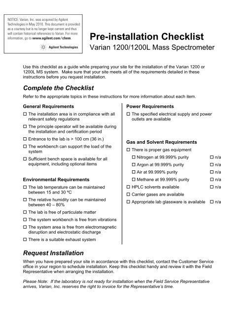
Pre-installation Checklist<strong>Varian</strong> 1200/<strong>1200L</strong> Mass SpectrometerUse this checklist as a guide while preparing your site for the installation of the <strong>Varian</strong> 1200 or<strong>1200L</strong> <strong>MS</strong> system. Make sure that your site meets all of the requirements detailed in theseinstructions before you request installation.Complete the ChecklistRefer to the appropriate topics in these instructions for more information about each item.General Requirements The installation area is in compliance with allrelevant safety regulations The principle operator will be available duringthe installation and certification period Entrance to the lab is > 100 cm (36 in.) The workbench can support the load of thesystem Sufficient bench space is available for allequipment, including optional itemsEnvironmental Requirements The lab temperature can be maintainedbetween 15 and 30 ºC The relative humidity can be maintainedbetween 40 – 80% The lab is free of particulate matter The system workbench is free from vibrations The system area is free from electromagneticdisruption and electrostatic discharge There is a suitable exhaust systemPower Requirements The specified electrical supply and poweroutlets are availableGas and Solvent Requirements There is proper gas equipment Nitrogen at 99.999% purity Argon at 99.999% purity Air at 99.999% purity Methane at 99.999% purity HP<strong>LC</strong> solvents available Carrier gases are available Appropriate lab glassware is available n/a n/a n/a n/a n/a n/aRequest InstallationWhen you have prepared your site in accordance with this checklist, contact the Customer Serviceoffice in your region to schedule installation. Keep this checklist handy and review it with the FieldRepresentative when arranging the installation.Please Note: If the laboratory is not ready for installation when the Field Service Representativearrives, <strong>Varian</strong>, Inc. reserves the right to invoice for the Representative’s time.
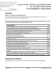
<strong>Varian</strong>,Inc.2700 Mitchell DriveWalnut Creek, CA 94598 U.S.A.1200/<strong>1200L</strong> <strong>GC</strong>/<strong>MS</strong> and <strong>LC</strong>/<strong>MS</strong>Pre-installation InstructionsCongratulations on your purchase of the <strong>Varian</strong> 1200 Quadrupole Mass Spectrometer. Theinformation provided in this pre-installation guide will help you prepare your installation site foryour <strong>Varian</strong> 1200 <strong>GC</strong>/<strong>MS</strong>, <strong>1200L</strong> <strong>GC</strong>/<strong>MS</strong>, <strong>1200L</strong> <strong>LC</strong>/<strong>MS</strong>, or <strong>1200L</strong> <strong>GC</strong>/<strong>LC</strong>/<strong>MS</strong> system. Use thegeneral requirements and the appropriate section of these pre-installation instructions as aguide while preparing the installation site. When your site meets all the requirements detailedin these instructions, contact the Customer Service office in your region to schedule installation.The <strong>Varian</strong> <strong>1200L</strong> <strong>LC</strong>/<strong>MS</strong> and 1200/<strong>1200L</strong> <strong>GC</strong>/<strong>MS</strong> have been designed to operate reliablyunder carefully controlled environmental conditions. It is the responsibility of the customer toprovide a suitable location, power source, and operating environment. Operating or maintaininga system in operational conditions outside of the power and operating environment limitsdescribed in this manual could cause failures of many types. The repair of such failures isspecifically excluded from the Warranty and Service contract conditions.CAUTIONAll phases of the installation site preparation must conform tolocal safety, electrical, and building codes. These codes takeprecedence over any recommendations in these instructions,and compliance to them is the responsibility of the customer.General Requirements.................................................. 2Operating Environment ........................................... 2Temperature/Humidity............................................. 2Particulate Matter .................................................... 2Vibration .................................................................. 2Exhaust System ...................................................... 21200 <strong>GC</strong>/<strong>MS</strong>................................................................. 3Entrance.................................................................. 3Space and Load Requirements............................... 3Power Requirements 1200 <strong>GC</strong>/<strong>MS</strong>......................... 4Gas Requirements 1200 <strong>GC</strong>/<strong>MS</strong> ............................ 5<strong>1200L</strong> <strong>GC</strong>/<strong>MS</strong>............................................................... 6Entrance.................................................................. 6Space and Load Requirements............................... 6Power Requirements <strong>1200L</strong> <strong>GC</strong>/<strong>MS</strong>....................... 7Gas Requirements <strong>1200L</strong> <strong>GC</strong>/<strong>MS</strong> .......................... 8<strong>1200L</strong> <strong>LC</strong>/<strong>MS</strong>.............................................................. 10Entrance................................................................ 10Space and Load Requirements ............................ 10Power Requirements <strong>1200L</strong> <strong>LC</strong>/<strong>MS</strong>...................... 11Gas Requirements <strong>1200L</strong> <strong>LC</strong>/<strong>MS</strong> ......................... 12Solvent Requirements <strong>1200L</strong> <strong>LC</strong>/<strong>MS</strong>.................... 13<strong>1200L</strong> <strong>GC</strong>/<strong>LC</strong>/<strong>MS</strong> ....................................................... 13Entrance................................................................ 13Space and Load Requirements ............................ 13Power Requirements <strong>1200L</strong> <strong>GC</strong>/<strong>LC</strong>/<strong>MS</strong> ............... 14Gas Requirements <strong>1200L</strong> <strong>GC</strong>/<strong>LC</strong>/<strong>MS</strong>................... 15Solvent Requirements <strong>1200L</strong> <strong>LC</strong>/<strong>MS</strong>.................... 18Instrument Arrival ....................................................... 19Inspection.............................................................. 19Unpacking and Installation.................................... 20Spare Parts ........................................................... 20Preventive Maintenance ....................................... 20Appendix 1. Module Specifications............................ 21Appendix 2. Power Consumption .............................. 22Appendix 3. NEMA Plugs and Power Outlets............ 2403-914961-00:6 1 of 24 1200/<strong>1200L</strong> <strong>MS</strong> Pre-installation Instructions
General RequirementsOperating EnvironmentThe customer is responsible for providing an acceptable operating environment. Attention paidto the operating environment will ensure the continued peak performance of the massspectrometer.Temperature/HumidityThe optimal operating temperature is between 18 and 21 °C (65 and 70 °F).NOTE: As laboratory temperature increases, system reliability decreases. All electroniccomponents generate heat while operating. This heat must be dissipated to the surrounding airif the components are to operate reliably.The turbomolecular pump temperature cutoff control protects the bearing to prolong the pumplifetime. A laboratory temperature above 30 °C (86 °F) may cause the pump to shut down.Operating the <strong>MS</strong> at optimal temperatures will prolong the turbo pump life.There must be good air flow around the system. Your air conditioning system must be capableof maintaining a constant temperature (within operational limits) in the immediate vicinity of thesystem. The average steady-state heat load of the <strong>1200L</strong> is 6,000 Btu, with a possible shorttermheat dissipation of 15,000 Btu during startup.Hot air vented from <strong>GC</strong> column ovens may contribute to room heating and to the resulting airconditioning load. Ducting the <strong>GC</strong> column oven air out of the lab reduces this heating effect.The relative humidity (RH) of the operating environment must be between 40 and 80%, with nocondensation. Operating the mass spectrometer at very low humidity may result in theaccumulation and discharge of static electricity, shortening the life of electronic components.Operating the system at high humidity may produce condensation and result in short circuits.<strong>Varian</strong> recommends that your laboratory be equipped with a temperature/humidity monitor. Thiswill ensure that your laboratory is always in conformance with temperature and humidityspecifications.Particulate MatterTake necessary precautions to minimize particulates in the laboratory environment. A layer ofdust on the electronic components could act as an insulating blanket and reduce heat transferto the surrounding air.VibrationEnsure that lab benches are free from vibrations, especially those caused by equipment inadjoining locations. Because the foreline pump vibrates during operation, install it on the floorbeneath the mass spectrometer, not alongside the system on the workbench. This is especiallyimportant when using the <strong>1200L</strong> <strong>LC</strong>, where two foreline pumps are required.Exhaust SystemIt is your responsibility to provide an adequate exhaust system. Most compounds introducedinto the mass spectrometer will eventually be exhausted from the foreline pump, along with thesmall amounts of oil vapor that these pumps characteristically emit. Therefore, the pump outletsshould be connected to a fume exhaust system. Consult local regulations for the proper methodof exhausting the fumes from your system. <strong>LC</strong>/<strong>MS</strong> systems will require venting of the foreline03-914961-00:6 2 of 24 1200/<strong>1200L</strong> <strong>MS</strong> Pre-installation Instructions
pumps of at least 2L/min, and venting of the API spray chamber of at least 12L/min to aseparate vent line. Ensure that the exhaust system does not pull a vacuum on the API chamber.1200 <strong>GC</strong>/<strong>MS</strong>EntranceBefore arranging for delivery of the 1200 <strong>GC</strong>/<strong>MS</strong> to your facility, please make sure that allpassages to the site of installation are at least 36 in. (110 cm) wide. Allow additional room formaneuvering the shipping containers around corners and/or through doors.CAUTIONThe 1200 <strong>MS</strong>, foreline pump, and gas chromatograph areheavy items that require at least two fit people for lifting andmoving safely.Space and Load RequirementsThe recommended layout for the 1200 <strong>MS</strong> with the gas chromatograph is illustrated in Figure 1below. The gas chromatograph must be positioned to the left of the instrument to allowconnection of the transfer line from the <strong>GC</strong> to the <strong>MS</strong>.NOTE: This figure illustrates North American power requirements (115 Vac). See Table 1 for230 Vac amperage requirements.Figure 1 Recommended 1200 <strong>GC</strong>/<strong>MS</strong> System Layout03-914961-00:6 3 of 24 1200/<strong>1200L</strong> <strong>MS</strong> Pre-installation Instructions
The 1200 <strong>GC</strong>/<strong>MS</strong> system should be installed on a clean, flat surface. The minimum benchspace required for the system is 57 cm x 195 cm, for the CP-3800 <strong>GC</strong>, 1200 <strong>MS</strong>, and PC:275 cm if the printer is on the bench as illustrated above. Ensure that the bench is capable ofsupporting the weight of the system: at least 150 kg plus allowances for any options.The foreline pump plugs directly into the <strong>MS</strong> and should be positioned on the floor beneath theworkbench on which the 1200 <strong>MS</strong> system sits. There is a 48 in. (1.2m) vacuum line from therear of the <strong>MS</strong> that connects to the foreline pump. To accommodate the pump, the workbenchshould be no higher than 36 in. (91 cm). If you use a higher bench, be sure to place avibrationally-isolated table or stand under the bench to elevate the pump. The table must becapable of supporting the 25 kg pump.If your bench adjoins a wall, you will need to drill a 1.5 in. (3.8 cm) diameter hole through therear of the bench to accommodate the vacuum hose.The PC can be positioned either alongside the <strong>GC</strong>/<strong>MS</strong>, or on a separate table. If a separatetable is chosen, it should be positioned within 10 ft (3m) of the rear of the 1200.NOTE: See Appendix 1 for exact module specifications.Power Requirements 1200 <strong>GC</strong>/<strong>MS</strong>The 1200 <strong>GC</strong>/<strong>MS</strong> system requires one dedicated duplex single-phase power source with earthgrounds hard-wired to the main power panel ground for the gas chromatograph, and a fourplexpower source for the mass spectrometer, computer, and monitor. If you have additional samplepreparation devices or test equipment, we recommend a separate dedicated power source fortheir operation. Never plug the mass spectrometer and the chromatograph into the same powersource, or you may overload the power source. Never use the free outlet on any of the powersources for equipment drawing more than 2A.Within North America these power sources must be 20A, 100-115 Vac 60 Hz ±3 Hz.Outside North America, power sources must be 10A, 200-240 Vac, 50 Hz ±3 Hz.Table 1 1200 <strong>GC</strong>/<strong>MS</strong> Power RequirementsInstrumentMax Current Draw110-115V (Amps)Max Current Draw200-240V (Amps)CP-3800 Gas Chromatograph 20 101200 Mass Spectrometer 12 6Computer 3 1.5Monitor 3 1.5Printer 3 1.5NOTE: See Appendix 2 for complete current supply requirements for the standard modules.The power cable from the <strong>GC</strong> is approximately 2 meters (80 in.) long and fitted with NationalElectronics Manufacturers Association (NEMA) 5-20P power plugs. The NEMA 5-20P powerplug and corresponding outlet are shown in Appendix 3 Figure 5(a). NEMA 5-20P plugs arerated at 20A and 120 Vac.The power cable from the mass spectrometer is approximately 8 ft (2.5m) long and fitted withNational Electronics Manufacturers Association (NEMA) 5-15P power plugs. The NEMA 5-15Ppower plug and corresponding outlet are shown in Appendix 3 Figure 5(b). NEMA 5-15P plugsare rated at 15A and 120 Vac. The power cables for the computer, monitor, and printer areapproximately 7 ft (2m) long. They are fitted with NEMA 5-15P plugs.Systems shipped outside the United States and Canada are fitted with CEE 7/7 plugs which arerated at 16A and 230 Vac. The CEE 7/7 plug and outlet are shown in Appendix 3 Figure 5(c).03-914961-00:6 4 of 24 1200/<strong>1200L</strong> <strong>MS</strong> Pre-installation Instructions
Gas Requirements 1200 <strong>GC</strong>/<strong>MS</strong>CI Reagent GasesThe CI mode for the 1200 <strong>MS</strong> typically uses methane, isobutane, or ammonia. The amount ofgas consumed during CI operation is approximately 1 to 2 mL/min. The CI reagent gas shouldcontain less than 1 ppm water. The methane, isobutane, or ammonia gas supply line connectsdirectly to the CI gas inlet using 1/8-inch Swagelok® fittings.Before evacuation, new gas lines typically contain significant amounts of adsorbed water vapor.The longer the gas line, the greater the pumping time required to evacuate the water from theline. To minimize pumping time, we recommend that the line be as short as possible.Methane 5.0 Research Grade (99.999% purity)A two-stage, 0−15 psi (0−1 bar) pressure regulator that has a stainless steel diaphragm isrecommended. The output pressure to the 1200 <strong>MS</strong> should be set to 3−5 psi (0.2−0.3 bar). Gaslines for methane should be made of stainless steel. All gas lines should be free of oil andpreferably flame treated or solvent washed.Isobutane 5.0 Research Grade (99.999% purity)A two-stage, 0−15 psi (0−1 bar) pressure regulator that has a stainless steel diaphragm isrecommended. The output pressure to the 1200 <strong>MS</strong> should be set to 3−5 psi (0.2−0.3 bar). Gaslines for isobutane should be made of stainless steel. All gas lines should be free of oil andpreferably flame treated or solvent washed.Ammonia 5.0 Research Grade (99.999% purity)A two-stage, 0−15 psi (0−1 bar) pressure regulator that has a stainless steel diaphragm isrecommended. The output pressure to the 1200 <strong>MS</strong> should be set to 3−5 psi (0.2−0.3 bar). Gaslines for ammonia should be made of stainless steel. All gas lines should be free of oil andpreferably flame treated or solvent washed.Ammonia, Anhydrous (CAS Number 7664-41-7)Anhydrous Ammonia gas is highly toxic. Inhalation may cause irritation to eyes andthroat and may cause pulmonary edema, which can result in serious injury or death.Repeated exposure to Anhydrous Ammonia may cause permanent lung damage.• Refer to Material Safety Data Sheet (<strong>MS</strong>DS) for Anhydrous Ammonia forexposure control/personal protection, handling/storage, accidental release, firstaid, and fire fighting measure requirements.• Anhydrous Ammonia should only be used in conjunction with an appropriateventilation system for the instrument, the exhaust from the foreline pump, andthe gas cylinder. Use appropriate safety shutoff valves for the AnhydrousAmmonia supply and interconnecting lines.The operator is responsible for determining and implementing appropriate precautionswhen using Anhydrous Ammonia and for compliance with all governmental regulations.It is the operator's responsibility to understand and adhere to all safe laboratorypractices concerning the use of toxic gases, including Anhydrous Ammonia.03-914961-00:6 5 of 24 1200/<strong>1200L</strong> <strong>MS</strong> Pre-installation Instructions
CID Gas (Triple Quad only)Argon is recommended for use as a collision gas for Collision Induced Dissociation (CID)<strong>MS</strong>/<strong>MS</strong> in the triple quadrupole <strong>MS</strong>, with typical flow rates of 1 mL/min. The argon must have apurity of greater than 99% and be regulated to 5 psi.<strong>GC</strong> Carrier GasesHeliumHelium is required as a carrier gas for the <strong>GC</strong>, with a minimum of 99.999% ultra-high purity, andless than 1.0 ppm each of water, oxygen, and total hydrocarbons. The minimum requirement isone 257 ft 3 tank with an Alltech regulator #AL8111, or equivalent tank and regulator. The outputgas pressure should be regulated to 80 psi.The presence of greater than 1 ppm oxygen or water in the carrier gas supply maysignificantly affect the performance of the 1200 <strong>GC</strong>/<strong>MS</strong>. It may also damage suchcomponents as the capillary column, filaments, and multiplier. <strong>Varian</strong> recommends thatyou verify that your gas suppliers use controlled tanks to ensure that purity standardsare maintained. If you purchase pure gases in contaminated tanks, you may end up witha contaminated system requiring costly and time-consuming repair.FilterUse of a carrier gas filter is required for optimum performance and to protect your system frompotential contamination. Your <strong>GC</strong> Accessory Kit includes a <strong>GC</strong>/<strong>MS</strong> Gas Clean Oxygen/Moisturefilter (CP-17973) and filter base. This easy-to-remove gas filter cartridge combines three highlyadsorptive materials in one filter to remove water, oxygen, and organic compounds to purify the<strong>GC</strong>/<strong>MS</strong> gas. Carrier gas filters should be installed in a location where the indicator is visible.The filter should be replaced when the indicator shows that the filter is saturated, or after oneyear of service. For replacement procedures, refer to the instructions enclosed with your filter.<strong>1200L</strong> <strong>GC</strong>/<strong>MS</strong>EntranceBefore arranging for delivery of the <strong>1200L</strong> <strong>GC</strong>/<strong>MS</strong> to your facility, please make sure that allpassages to the site of installation are at least 36 in. (110 cm) wide. Allow additional room formaneuvering the shipping containers around corners and/or through doors.CAUTIONThe 1200 <strong>MS</strong>, foreline pump, and gas chromatograph areheavy items that require at least two fit people for liftingand moving safely.Space and Load RequirementsThe required layout for the <strong>1200L</strong> <strong>MS</strong> with the gas chromatograph is illustrated in Figure 2. Thegas chromatograph must be positioned to the left of the instrument to allow connection of thetransfer line from the <strong>GC</strong> to the <strong>MS</strong>.NOTE: This figure illustrates North American power requirements (115 Vac). See Table 2 for230 Vac amperage requirements.03-914961-00:6 6 of 24 1200/<strong>1200L</strong> <strong>MS</strong> Pre-installation Instructions
Figure 2 Recommended <strong>1200L</strong> <strong>GC</strong>/<strong>MS</strong> System LayoutThe <strong>1200L</strong> <strong>GC</strong>/<strong>MS</strong> system should be installed on a clean, flat surface. The minimum benchspace required for the system is 57 cm x 195 cm, for the CP-3800 <strong>GC</strong>, 1200<strong>MS</strong>, and PC;275 cm with the printer. Ensure that the bench is capable of supporting the weight of thesystem: at least 150 kg plus allowances for any options.The foreline pump plugs directly into the <strong>MS</strong>, and should be positioned on the floor beneath theworkbench on which the 1200 <strong>MS</strong> system sits. There is a 96 in. (2.44m) vacuum line from theback, left of the <strong>MS</strong> that connects to the foreline pump.The PC can be positioned either alongside the <strong>GC</strong>/<strong>MS</strong> or on a separate table. If a separatetable is chosen, it should be positioned within 10 ft (3m) of the rear of the <strong>1200L</strong>.NOTE: See Appendix 1 for exact module specifications.Power Requirements <strong>1200L</strong> <strong>GC</strong>/<strong>MS</strong>The <strong>1200L</strong> <strong>GC</strong>/<strong>MS</strong> system requires one dedicated duplex single-phase power source with earthgrounds hard-wired to the main power panel ground for the gas chromatograph, and a fourplexpower source for the mass spectrometer, computer, and monitor. If you have additional samplepreparation devices or test equipment, we recommend a separate dedicated power source fortheir operation. Never plug the mass spectrometer and the chromatograph into the same powersource; otherwise, you may overload the power source. Never use the free outlet on any of thepower sources for equipment drawing more than 2A.Within North America these power sources must be 20A, 100-115 Vac 60 Hz ±3 Hz.Outside North America, power sources must be 10A, 200-240 Vac, 50 Hz ±3 Hz.03-914961-00:6 7 of 24 1200/<strong>1200L</strong> <strong>MS</strong> Pre-installation Instructions
Table 2 <strong>1200L</strong> <strong>GC</strong>/<strong>MS</strong> Power RequirementsInstrumentMax Current Draw100-115V (Amps)Max Current Draw200-240V (Amps)CP-3800 Gas Chromatograph 20 101200 Mass Spectrometer 12 6Computer 3 1.5Monitor 3 1.5Printer 3 1.5NOTE: See Appendix 2 for complete current supply requirements for the standard modules.The power cable from the <strong>GC</strong> is approximately 80 in. (2 meters) long and fitted with NationalElectronics Manufacturers Association (NEMA) 5-20P power plugs. The NEMA 5-20P powerplug and corresponding outlet are shown in Appendix 3 Figure 5(a). NEMA 5-20P plugs arerated at 20A and 120 Vac.The power cable from the mass spectrometer is approximately 98 in. (2.5m) long and fitted withNational Electronics Manufacturers Association (NEMA) 5-15P power plugs. The NEMA 5-15Ppower plug and corresponding outlet are shown in Appendix 3 Figure 5(b). NEMA 5-15P plugsare rated at 15A and 120 Vac.The power cables for the computer, monitor, and printer are approximately 80 in. (2m) long.They are fitted with NEMA 5-15P plugs.Systems shipped outside the United States and Canada are fitted with CEE 7/7 plugs which arerated at 16A and 230 Vac. The CEE 7/7 plug and outlet are shown in Appendix 3 Figure 5(c).Gas Requirements <strong>1200L</strong> <strong>GC</strong>/<strong>MS</strong>CI Reagent GasesThe CI mode for the <strong>1200L</strong> <strong>MS</strong> typically uses methane, isobutane, or ammonia. The amount ofgas consumed during CI operation is approximately 1 to 2 mL/min. The CI reagent gas shouldcontain less than 1 ppm water. The methane, isobutane, or ammonia gas supply line connectsdirectly to the CI gas inlet using 1/8-inch Swagelok fittings.Before evacuation, new gas lines typically contain significant amounts of adsorbed water vapor.The longer the gas line, the greater the pumping time required to evacuate the water from theline. To minimize pumping time, we recommend that the line be as short as possible.Methane 5.0 Research Grade (99.999% purity)A two-stage, 0−15 psi (0−1 bar) pressure regulator that has a stainless steel diaphragm isrecommended. The output pressure to the 1200 <strong>MS</strong> should be set to 3−5 psi (0.2−0.3 bar). Gaslines for methane should be made of stainless steel. All gas lines should be free of oil andpreferably flame treated or solvent washed.Isobutane 5.0 Research Grade (99.999% purity)A two-stage, 0−15 psi (0−1 bar) pressure regulator that has a stainless steel diaphragm isrecommended. The output pressure to the 1200 <strong>MS</strong> should be set to 3−5 psi (0.2−0.3 bar). Gaslines for isobutane should be made of stainless steel. All gas lines should be free of oil andpreferably flame treated or solvent washed.03-914961-00:6 8 of 24 1200/<strong>1200L</strong> <strong>MS</strong> Pre-installation Instructions
Ammonia 5.0 Research Grade (99.999% purity)A two-stage, 0−15 psi (0−1 bar) pressure regulator that has a stainless steel diaphragm isrecommended. The output pressure to the 1200 <strong>MS</strong> should be set to 3−5 psi (0.2−0.3 bar). Gaslines for ammonia should be made of stainless steel. All gas lines should be free of oil andpreferably flame treated or solvent washed.Ammonia, Anhydrous (CAS Number 7664-41-7)Anhydrous Ammonia gas is highly toxic. Inhalation may cause irritation to eyes andthroat and may cause pulmonary edema, which can result in serious injury or death.Repeated exposure to Anhydrous Ammonia may cause permanent lung damage.• Refer to Material Safety Data Sheet (<strong>MS</strong>DS) for Anhydrous Ammonia forexposure control/personal protection, handling/storage, accidental release,first aid, and fire fighting measure requirements.• Anhydrous Ammonia should only be used in conjunction with an appropriateventilation system for the instrument, the exhaust from the foreline pump, andthe gas cylinder. Use appropriate safety shutoff valves for the AnhydrousAmmonia supply and interconnecting lines.The operator is responsible for determining and implementing appropriate precautionswhen using Anhydrous Ammonia and for compliance with all governmentalregulations. It is the operator's responsibility to understand and adhere to all safelaboratory practices concerning the use of toxic gases, including Anhydrous Ammonia.CID Gas (Triple Quad only)Argon is recommended for use as a collision gas for Collision Induced Dissociation (CID)<strong>MS</strong>/<strong>MS</strong> in the triple quadrupole <strong>MS</strong>, with typical flow rates of 1 mL/min. The argon must have apurity of greater than 99%, and be regulated to 5 psi.<strong>GC</strong> Carrier GasesHeliumHelium is required as a carrier gas for the <strong>GC</strong>, with a minimum of 99.999% ultra-high purity, andless than 1.0 ppm each of water, oxygen, and total hydrocarbons. The minimum requirement isone 257 ft 3 tank with an Alltech regulator #AL8111, or equivalent tank and regulator.The presence of greater than 1 ppm oxygen or water in the carrier gas supply maysignificantly affect the performance of the 1200 <strong>GC</strong>/<strong>MS</strong>. It may also damage suchcomponents as the capillary column, filaments, and multiplier. <strong>Varian</strong> recommends thatyou verify that your gas suppliers use controlled tanks to ensure that purity standardsare maintained. If you purchase pure gases in contaminated tanks, you may end up witha contaminated system requiring costly and time-consuming repair.03-914961-00:6 9 of 24 1200/<strong>1200L</strong> <strong>MS</strong> Pre-installation Instructions
FilterUse of a carrier gas filter is required for optimum performance and to protect your system frompotential contamination. Your <strong>GC</strong> Accessory Kit includes a <strong>GC</strong>/<strong>MS</strong> Gas Clean Oxygen/Moisturefilter (CP-17973) and filter base. This easy-to-remove gas filter cartridge combines three highlyadsorptive materials in one filter to remove water, oxygen, and organic compounds to purify the<strong>GC</strong>/<strong>MS</strong> gas. Carrier gas filters should be installed in a location where the indicator is visible.The filter should be replaced when the indicator shows that the filter is saturated, or after oneyear of service. For replacement procedures, refer to the instructions enclosed with your filter.<strong>1200L</strong> <strong>LC</strong>/<strong>MS</strong>EntranceBefore arranging for delivery of the <strong>1200L</strong> <strong>LC</strong>/<strong>MS</strong> to your facility, please make sure that allpassages to the site of installation are at least 36 in. (91.5 cm) wide. Allow additional room formaneuvering the shipping containers around corners and/or through doors.CAUTIONThe <strong>1200L</strong> <strong>MS</strong>, foreline pumps, and Liquid Chromatographare heavy items that require at least two fit people for liftingand moving safely.Space and Load RequirementsThe required layout for the <strong>1200L</strong> <strong>MS</strong> with the <strong>LC</strong> is illustrated in Figure 3. The <strong>LC</strong> should bepositioned to the left of the instrument to minimize the delay volume between the <strong>LC</strong> and the<strong>MS</strong>.NOTE: This figure illustrates North American power requirements (115 Vac). See Table 3 for230 Vac amperage requirements.03-914961-00:6 10 of 24 1200/<strong>1200L</strong> <strong>MS</strong> Pre-installation Instructions
Figure 3 Recommended <strong>1200L</strong> <strong>LC</strong>/<strong>MS</strong> System LayoutThe <strong>1200L</strong> <strong>LC</strong>/<strong>MS</strong> system should be installed on a clean, flat surface. The minimum benchspace required for the system is 57 cm x 210 cm for the <strong>LC</strong>, 1200, and PC, 275 cm with theprinter. Ensure that the bench is capable of supporting the weight of the system: at least 200 kgplus allowances for any options.The <strong>1200L</strong> <strong>MS</strong> uses two foreline pumps that should be positioned on the floor beneath theworkbench on which the <strong>1200L</strong> <strong>MS</strong> system sits. There is a 96 in. (2.44m) vacuum line from theback, left of the <strong>MS</strong> that connects to the foreline pumps, and a pump controller that must bepositioned within 80 in. (2m) of the <strong>MS</strong>.Power Requirements <strong>1200L</strong> <strong>LC</strong>/<strong>MS</strong>The <strong>1200L</strong> <strong>LC</strong>/<strong>MS</strong> system requires two dedicated fourplex single-phase power sources withearth grounds hard-wired to the main power panel ground, and one 230V 20A power source.One of these fourplex power sources is for the mass spectrometer, computer, and monitor; theother fourplex power source is for the liquid chromatograph, and the 230V 20A source is for theforeline pumps. If you have additional sample preparation devices or test equipment, werecommend a separate dedicated power source for their operation. Never plug the massspectrometer and the chromatograph into the same power source, or you may overload thefourplex power source. Never use the free outlet on any of the power sources for equipmentdrawing more than 2A.Within North America these power sources must be 20A, 120 Vac, 60 Hz ±3 Hz and 20A,230 Vac, 60 Hz ±3 Hz for the two foreline pumps.Outside North America power sources must be 10A, 230 Vac, 50 Hz ±3 Hz and 20A, 230V50 Hz ±3 Hz for the two foreline pumps.03-914961-00:6 11 of 24 1200/<strong>1200L</strong> <strong>MS</strong> Pre-installation Instructions
Table 3 <strong>1200L</strong> <strong>LC</strong>/<strong>MS</strong> Power RequirementsInstrumentMax Current Draw100-115V (Amps)Max Current Draw200-240V (Amps)ProStar 210/215 Pumps 2.25 each 1.125 eachProStar 430 AutoSampler 2 1<strong>1200L</strong> Mass Spectrometer 12 6602 Foreline pumps Not recommended 20Computer 3 1.5Monitor 3 1.5Printer 3 1.5NOTE: See Appendix 2 for complete current supply requirements for the standard modules.The power cable from the mass spectrometer is approximately 98 in. (2.5m) long and fitted withNational Electronics Manufacturers Association (NEMA) 5-15P power plugs. The NEMA 5-15Ppower plug and corresponding outlet are shown in Appendix 3 Figure 5(b). NEMA 5-15P plugsare rated at 15A and 120 Vac.The power cable from the foreline pump box for the <strong>LC</strong>/<strong>MS</strong> is approximately 78 in. (2m) longand fitted with a National Electronics Manufacturers Association (NEMA) 6-20 power plug. TheNEMA 6-20 plugs are rated at 20A and 220 Vac. The NEMA 6-20 plug and corresponding outletare shown in Appendix 3 Figure 5(d).The power cables for the computer, monitor, and printer are approximately 78 in. (2m) long.They are fitted with NEMA 5-15P plugs.Systems shipped outside the United States and Canada are fitted with CEE 7/7 plugs which arerated at 16A and 230 Vac. The CEE 7/7 plug and outlet are shown in Appendix 3 Figure 5(c).Gas Requirements <strong>1200L</strong> <strong>LC</strong>/<strong>MS</strong>NitrogenA Nitrogen gas supply capable of providing up to 12L/min of gas regulated at 80 psi is requiredas a nebulizing and drying gas. The nitrogen must have a purity greater than 99%, with lessthan 0.1 ppm hydrocarbons, and less than 1% oxygen. The nitrogen should be dry, with a −40degree dew point. <strong>Varian</strong> recommends the use of a nitrogen generator, or liquid nitrogen blowoffto supply the gas. All nitrogen generators require regular maintenance to continue to performto specification. The nitrogen generator manufacturer should be consulted as to preventativemaintenance requirements of the instrument, and the schedule must be followed. Any problemswith the <strong>MS</strong> that are found to be caused by poor gas quality are not covered under Warranty. Itis the customer’s responsibility to conform to all regulations regarding the installation andoperation of the gas system.AirA compressed air gas supply that is capable of providing up to 2L/min of gas regulated to 80 psiis required for negative ESI as a nebulizing gas. It is the customer's responsibility to conform toall regulations regarding the installation and operation of the gas system. The air should beclean and dry, with less than 0.1 ppm total hydrocarbons, including methane, and a −40 degreedew point.03-914961-00:6 12 of 24 1200/<strong>1200L</strong> <strong>MS</strong> Pre-installation Instructions
CID Gas (Triple Quad only)Argon is recommended for use as a Collision Induced Dissociation gas for <strong>MS</strong>/<strong>MS</strong> in the triplequadrupole <strong>MS</strong>, with a typical flow rate of 1 mL/min. The argon must have a purity of greaterthan 99% and be regulated to 1−3 psi (0.1−0.2 bar).Solvent Requirements <strong>1200L</strong> <strong>LC</strong>/<strong>MS</strong>Installation by a <strong>Varian</strong> Field Service Representative will normally include a basic test of thesystem’s functionality.Mobile phase solvents required for installation are methanol and de-ionized water. All solventsshould be pure HP<strong>LC</strong>-grade, and degassing apparatus should be available, if required.You will need to provide the following glassware for diluting the standards used to masscalibrate the instrument:• two 50 mL volumetric flasks• two 1.0 mL pipettesIn addition to the above, interconnect tubing will be required to complete installation of yoursystem. Most of this tubing is included in the accessory kits of specific <strong>LC</strong> instrument modules.Additional tubing (PEEK® or Stainless Steel) may be required for installation of special valvingor installation of modules to existing HP<strong>LC</strong> systems.For most analytical HP<strong>LC</strong> systems (flow rates up to 10 mL/min), 1/16" tubing with an internaldiameter (ID) of 0.005” can be used throughout. However, 0.005" ID or smaller should alwaysbe used downstream of the sample injector or autosampler to prevent peak broadening. Inaddition, tubing lengths should always be kept to a minimum.Semiprep and Preparative systems have other requirements/limitations with regard tointerconnect tubing. Typically, a system using flow rates up to 200 mL/min will require 1/16" ODtubing with an internal diameter as high as 0.040". On these systems, tubing ID used after theinjector/autosampler should be ~0.010" smaller than tubing used in the rest of the system. OnPrep systems, 1/8" tubing (0.062" or 0.080" ID) is typically used throughout. Always consult theinstrument module Operator’s Manual for specific recommendations.<strong>1200L</strong> <strong>GC</strong>/<strong>LC</strong>/<strong>MS</strong>EntranceBefore arranging for delivery of the <strong>1200L</strong> <strong>GC</strong>/<strong>LC</strong>/<strong>MS</strong> to your facility, please make sure that allpassages to the site of installation are at least 36 in. (91.5 cm) wide. Allow additional room formaneuvering the shipping containers around corners and/or through doors.CAUTIONThe <strong>1200L</strong> <strong>MS</strong>, foreline pumps, <strong>GC</strong>, and <strong>LC</strong> are heavy itemsthat require at least two fit people for lifting and movingsafely.Space and Load RequirementsThe required layout for the <strong>1200L</strong> <strong>MS</strong> with the HP<strong>LC</strong> is illustrated in Figure 4. The gaschromatograph must be positioned to the left of the instrument to allow connection of thetransfer line from the <strong>GC</strong> to the <strong>MS</strong>. The <strong>1200L</strong> <strong>MS</strong> uses two foreline pumps that should bepositioned on the floor beneath the workbench on which the <strong>1200L</strong> <strong>MS</strong> system sits. There is a96 in. (2.44m) vacuum line from the back, left of the <strong>MS</strong> that connects to the foreline pumps,and a pump controller that must be positioned within 80 in. (2m) of the <strong>MS</strong>.03-914961-00:6 13 of 24 1200/<strong>1200L</strong> <strong>MS</strong> Pre-installation Instructions
NOTE: This figure illustrates North American power requirements (115 Vac). See Table 4 for230 Vac amperage requirements.Figure 4 Recommended <strong>1200L</strong> <strong>GC</strong>/<strong>LC</strong>/<strong>MS</strong> System LayoutThe <strong>1200L</strong> <strong>GC</strong>/<strong>LC</strong>/<strong>MS</strong> system should be installed on a clean, flat surface. The minimum benchspace required for the system is 57 cm x 250 cm for the HP<strong>LC</strong>, 1200, and PC, 325 cm with theprinter. Ensure that the bench is capable of supporting the weight of the system: at least 250 kgplus allowances for any options.Power Requirements <strong>1200L</strong> <strong>GC</strong>/<strong>LC</strong>/<strong>MS</strong>The <strong>1200L</strong> <strong>GC</strong>/<strong>LC</strong>/<strong>MS</strong> system requires a dedicated duplex power source for the <strong>GC</strong>, twodedicated fourplex single-phase power sources with earth grounds hard-wired to the mainpower panel ground for the HP<strong>LC</strong>, <strong>MS</strong>, and computer, and one 230V 20A power source for theforeline pumps. If you have additional sample preparation devices or test equipment, werecommend a separate dedicated power source for their operation. Never plug the massspectrometer and the chromatograph into the same power source, or you may overload thefourplex power source. Never use the free outlet on any of the power sources for equipmentdrawing more than 2AWithin North America these power sources must be 20A, 120 Vac, 60 Hz ±3 Hz and 20A,230 Vac, 60 Hz ±3 Hz for the two foreline pumps.Outside North America power sources must be 10A, 230 Vac, 50 Hz ±3 Hz and 20A, 230V50 Hz ±3 Hz for the two foreline pumps.03-914961-00:6 14 of 24 1200/<strong>1200L</strong> <strong>MS</strong> Pre-installation Instructions
Table 4 <strong>1200L</strong> <strong>GC</strong>/<strong>LC</strong>/<strong>MS</strong> Power RequirementsInstrumentMax Current Draw100-115V (Amps)Max Current Draw200-240V (Amps)CP-3800 Gas Chromatograph 20 10ProStar 210/215 Pumps 2.25 each 1.125 eachProStar 430 AutoSampler 2 1<strong>1200L</strong> Mass Spectrometer 12 6602 Foreline pumps Not recommended 20Computer 3 1.5Monitor 3 1.5Printer 3 1.5NOTE: See Appendix 2 for complete current supply requirements for the standard modules.The power cable from the mass spectrometer is approximately 98 in. (2.5m) long and fitted withNational Electronics Manufacturers Association (NEMA) 5-15P power plugs. The NEMA 5-15Ppower plug and corresponding outlet are shown in Appendix 3 Figure 5(b). NEMA 5-15P plugsare rated at 15A and 120 Vac.The power cable from the foreline pump box for the <strong>LC</strong>/<strong>MS</strong> is approximately 78 in. (2m) longfitted with a National Electronics Manufacturers Association (NEMA) 6-20P power plug. TheNEMA 6-20P plugs are rated at 20A and 220 Vac. The NEMA 6-20P plug and correspondingoutlet are shown in Appendix 3 Figure 5(d).The power cable from the <strong>GC</strong> is approximately 78 in. (2m) long and fitted with NationalElectronics Manufacturers Association (NEMA) 5-20P power plugs. The NEMA 5-20P powerplug and corresponding outlet are shown in Appendix 3 Figure 5(a). NEMA 5-20P plugs arerated at 20A and 120 Vac.The power cables for the computer, monitor, and printer are approximately 78 in. (2m) long.They are fitted with NEMA 5-15P plugs.Systems shipped outside the United States and Canada are fitted with CEE 7/7 plugs which arerated at 16A and 230 Vac. The CEE 7/7 plug and outlet are shown in Appendix 3 Figure 5(c).Gas Requirements <strong>1200L</strong> <strong>GC</strong>/<strong>LC</strong>/<strong>MS</strong>NitrogenA Nitrogen gas supply capable of providing up to 12L/min of gas regulated at 80 psi is requiredas a nebulizing and drying gas. The nitrogen must have a purity greater than 99%, with lessthan 0.1 ppm hydrocarbons, and less than 1% oxygen. The nitrogen should be dry, with a −40degree dew point. <strong>Varian</strong> recommends the use of a nitrogen generator, or liquid nitrogen blowoffto supply the gas. All nitrogen generators require regular maintenance to continue to performto specification. The nitrogen generator manufacturer should be consulted as to preventativemaintenance requirements of the instrument, and the schedule must be followed. Any problemswith the <strong>MS</strong> that are found to be caused by poor gas quality are not covered under Warranty. Itis the customer’s responsibility to conform to all regulations regarding the installation andoperation of the gas system.03-914961-00:6 15 of 24 1200/<strong>1200L</strong> <strong>MS</strong> Pre-installation Instructions
AirA compressed air gas supply that is capable of providing up to 2L/min regulated to 80 psi isrequired for negative ESI as a nebulizing gas. It is the customer's responsibility to conform to allregulations regarding the installation and operation of the gas system. The air should be cleanand dry, with less than 0.1 ppm total hydrocarbons, including methane, and a –40 degree dewpoint.CI Reagent GasesThe CI mode for the <strong>1200L</strong> <strong>MS</strong> typically uses methane, isobutane, or ammonia. The amount ofgas consumed during CI operation is approximately 1 to 2 mL/min. The CI reagent gas shouldcontain less than 1 ppm water. The methane, isobutane, or ammonia gas supply line connectsdirectly to the CI gas inlet using 1/8” Swagelok fittings.Before evacuation, new gas lines typically contain significant amounts of adsorbed water vapor.The longer the gas line, the greater the pumping time required to evacuate the water from theline. To minimize pumping time, we recommend that the line be as short as possible.Methane 5.0 Research Grade (99.999% purity)A two-stage, 0−15 psi (0−1 bar) pressure regulator that has a stainless steel diaphragm isrecommended. The output pressure to the 1200 <strong>MS</strong> should be set to 3−5 psi (0.2−0.3 bar). Gaslines for methane should be made of stainless steel. All gas lines should be free of oil andpreferably flame treated or solvent washed.Isobutane 5.0 Research Grade (99.999% purity)A two-stage, 0−15 psi (0−1 bar) pressure regulator that has a stainless steel diaphragm isrecommended. The output pressure to the 1200 <strong>MS</strong> should be set to 3−5 psi (0.2−0.3 bar). Gaslines for isobutane should be made of stainless steel. All gas lines should be free of oil andpreferably flame treated or solvent washed.Ammonia 5.0 Research Grade (99.999% purity)A two-stage, 0−15 psi (0−1 bar) pressure regulator that has a stainless steel diaphragm isrecommended. The output pressure to the 1200 <strong>MS</strong> should be set to 3−5 psi (0.2−0.3 bar). Gaslines for ammonia should be made of stainless steel. All gas lines should be free of oil andpreferably flame treated or solvent washed.03-914961-00:6 16 of 24 1200/<strong>1200L</strong> <strong>MS</strong> Pre-installation Instructions
Ammonia, Anhydrous (CAS Number 7664-41-7)Anhydrous Ammonia gas is highly toxic. Inhalation may cause irritation to eyes andthroat and may cause pulmonary edema, which can result in serious injury or death.Repeated exposure to Anhydrous Ammonia may cause permanent lung damage.• Refer to Material Safety Data Sheet (<strong>MS</strong>DS) for Anhydrous Ammonia forexposure control/personal protection, handling/storage, accidental release,first aid, and fire fighting measure requirements.• Anhydrous Ammonia should only be used in conjunction with an appropriateventilation system for the instrument, the exhaust from the foreline pump, andthe gas cylinder. Use appropriate safety shutoff valves for the AnhydrousAmmonia supply and interconnecting lines.The operator is responsible for determining and implementing appropriate precautionswhen using Anhydrous Ammonia and for compliance with all governmentalregulations. It is the operator's responsibility to understand and adhere to all safelaboratory practices concerning the use of toxic gases, including Anhydrous Ammonia.CID Gas (Triple Quad only)Argon is recommended for use as a Collision Induced Dissociation gas for <strong>MS</strong>/<strong>MS</strong> in the triplequadrupole <strong>MS</strong>, with a typical flow rate of 1 mL/min. The argon must have a purity of greaterthan 99%, and be regulated to 1−3 psi (0.1−0.2 bar).<strong>GC</strong> Carrier GasHeliumHelium is required as a carrier gas for the <strong>GC</strong>, with a minimum 99.999% ultra-high purity, andless than 1.0 ppm each of water, oxygen, and total hydrocarbons. The minimum requirement isone 257 ft 3 tank with an Alltech regulator #AL8111, or equivalent tank and regulator.The presence of greater than 1 ppm oxygen or water in the carrier gas supply maysignificantly affect the performance of the 1200 <strong>GC</strong>/<strong>MS</strong>. It may also damage suchcomponents as the capillary column, filaments, and multiplier. <strong>Varian</strong> recommends thatyou verify that your gas suppliers use controlled tanks to ensure that purity standardsare maintained. If you purchase pure gases in contaminated tanks, you may end up witha contaminated system requiring costly and time-consuming repair.FilterUse of a carrier gas filter is required for optimum performance and to protect your system frompotential contamination. Your <strong>GC</strong> Accessory Kit includes a <strong>GC</strong>/<strong>MS</strong> Gas Clean Oxygen/Moisturefilter (part number CP-17973) and filter base. This easy-to-remove gas filter cartridge combinesthree highly adsorptive materials in one filter to remove water, oxygen, and organic compoundsto purify the <strong>GC</strong>/<strong>MS</strong> gas. Carrier gas filters should be installed in a location where the indicatoris visible. The filter should be replaced when the indicator shows that the filter is saturated, orafter one year of service. For replacement procedures, refer to the instructions enclosed withyour filter.03-914961-00:6 17 of 24 1200/<strong>1200L</strong> <strong>MS</strong> Pre-installation Instructions
Solvent Requirements <strong>1200L</strong> <strong>LC</strong>/<strong>MS</strong>Installation by a <strong>Varian</strong> Field Service Representative will normally include a basic test of thesystems functionality.Mobile phase solvents required for installation are methanol and de-ionized water. All solventsshould be pure HP<strong>LC</strong>-grade, and degassing apparatus should be available, if required.You will need to provide the following glassware for diluting the standards used to tune theinstrument:• two 50 mL volumetric flasks• two 1.0 mL pipettesIn addition to the above, interconnect tubing will be required to complete installation of yoursystem. Most of this tubing is included in the accessory kits of specific <strong>LC</strong> instrument modules.Additional tubing (PEEK® or stainless steel) may be required for installation of special valving,or installation of modules to existing HP<strong>LC</strong> systems.For most analytical HP<strong>LC</strong> systems (flow rates up to 10 mL/min), 1/16" tubing with an internaldiameter (ID) of 0.005" can be used throughout. However, 0.005" ID or smaller should alwaysbe used downstream of the sample injector or autosampler to prevent peak broadening. Inaddition, tubing lengths should always be kept to a minimum.Semiprep and Preparative systems have other requirements/limitations with regard tointerconnect tubing. Typically, a system using flow rates up to 200 mL/min will require 1/16" ODtubing with an internal diameter as high as 0.040". On these systems, tubing ID used after theinjector/autosampler should be ~0.010" smaller than tubing used in the rest of the system. OnPrep systems, 1/8" tubing (0.062" or 0.080" ID) is typically used throughout. Always consult theinstrument module Operation Manual for specific recommendations.03-914961-00:6 18 of 24 1200/<strong>1200L</strong> <strong>MS</strong> Pre-installation Instructions
Instrument ArrivalInspectionWhen the <strong>1200L</strong> <strong>LC</strong>/<strong>MS</strong> or 1200/<strong>1200L</strong> <strong>GC</strong>/<strong>MS</strong>arrives, carefully inspect the exterior of theshipping cartons for evidence of any damage thatmight have occurred during shipment. Inspect thecartons for the following:• Water stains• Cuts, punctures, or deep indentations• Crushed corners or excessively abraded edges• Beads in the Tip (N) Tell device.Two Tip (N) Tell indicators and labels are affixed tothe exterior of the shipping boxes. Read and followthe instructions on the label. If there are beads inthe arrow portion of the indicator, the box mayhave been tipped and instrument damage mayhave occurred during shipping.If one or more of the above conditions are evident on any of the shipping cartons, report theconditions to the carrier at time of receipt. Note the damage on all copies of the shippingdocuments, and briefly describe in writing the damage. The driver should sign next to yourcomments to signify agreement with the observations. Contact the appropriate <strong>Varian</strong> office toreport the damage.If no external damage is apparent, receiving documents should be signed “Received but notinspected” to indicate that the boxes have not been opened.Systems are shipped either FOB <strong>Varian</strong> or FOB Destination. The manner of shipmentdetermines who has responsibility for filing a claim against the carrier if the system is damagedin transit. Most systems are shipped FOB <strong>Varian</strong>, and any damages incurred in shipment arethe responsibility of the purchaser and the carrier. Contact the <strong>Varian</strong> office for assistance withclaims filing and billing for repairs if necessary. If the system is shipped FOB Destination,contact the <strong>Varian</strong> office, who will file a claim against the carrier.<strong>Varian</strong> will not accept liability for damage if obviously damaged materials are receivedwithout noting damage on the receiving documents.Move the shipping containers to a warm, dry, secure area near the place of installation. Do notopen any of the boxes until the <strong>Varian</strong> field Service Representative arrives for installation.03-914961-00:6 19 of 24 1200/<strong>1200L</strong> <strong>MS</strong> Pre-installation Instructions
Unpacking and InstallationBefore coming on site for installation, a <strong>Varian</strong> Field Service Representative will contact you togo through the “Pre-installation Checklist” at the front of this document to ensure that all of thesite requirements have been met. The <strong>Varian</strong> Field Service Representative will unpack andinstall the <strong>1200L</strong> <strong>LC</strong>/<strong>MS</strong> or 1200/<strong>1200L</strong> <strong>GC</strong>/<strong>MS</strong> and will demonstrate the fundamental operationand maintenance of the <strong>MS</strong>. It is therefore important to have the system operator availableduring the installation. The <strong>Varian</strong> Field Service Representative will only use the <strong>Varian</strong>supplied computer to perform the testing of system specifications. <strong>Varian</strong> does not guaranteethe workstation software to function on any other computer hardware or operating system.The <strong>Varian</strong> Field Service Representative will also demonstrate that your system meets theperformance specifications written into your sales contract. Do not plan to analyze samples withthe system until after the installation has been completed and you have accepted the conditionsof delivery.Spare PartsThe 1200/<strong>1200L</strong> Hardware Operation Manual provides a list of spare parts for routineoperation.Preventive MaintenanceThe customer is responsible for performing routine and preventive maintenance of thechromatograph, mass spectrometer, and data system. Any nitrogen generator used will requirepreventative maintenance to ensure the nitrogen supply is clean and dry. Any instrumentproblems that are a result of a contaminated gas supply are billable and not included in theWarranty.It is essential to perform regular preventive maintenance to increase the life of the system,maximize system uptime, and optimize system performance. Refer to the 1200/<strong>1200L</strong>Hardware Operation Manual for details. Your <strong>Varian</strong> Field Service Representative will describeand demonstrate these procedures at the time of installation.Trademark AcknowledgmentMicrosoft® and Windows® are registered trademarks of Microsoft Corporation. Swagelok is aregistered trademark of Swagelok Company, Solon, Ohio. Other brand and product names aretrademarks or registered trademarks of their respective holders.03-914961-00:6 20 of 24 1200/<strong>1200L</strong> <strong>MS</strong> Pre-installation Instructions
Appendix 1. Module SpecificationsThe following table identifies the space and weight requirements for <strong>Varian</strong> <strong>MS</strong>, <strong>LC</strong>, and <strong>GC</strong>components. <strong>Varian</strong> <strong>MS</strong> systems are intended to sit on a workbench that is wide enough anddeep enough to accommodate these components, and sturdy enough to support their combinedweight. Please note that some of the <strong>LC</strong> modules are stackable and that the <strong>GC</strong>/<strong>MS</strong> systemswill require enough extra bench space to allow the <strong>GC</strong> to be moved away from the <strong>MS</strong> forservicing and replacement of the transfer line.Table 5 Dimensions and Weights of the 1200/<strong>1200L</strong> System ComponentsHeight Width Depth WeightInstrument in. cm in. cm in. cm lb. kg1200 <strong>MS</strong>* 21 53 45 114 22.5 57.15 141* 62.5*<strong>1200L</strong> <strong>MS</strong>* 21 53 45 114 24.8 63 227* 103*ProStar 210, 220, 230, 240 11.5 29.2 11.5 29.2 20 51 53 24PrepStar 218, 530 7.75 19.7 11.5 29.2 18.25 46.4 48 22PrepStar SD-1 10.5 27 16 41 22 56 75 34PrepStar SD-2 7.75 19.7 11.5 29.2 20.25 57.5 60 27ProStar 500 Column Valve Module 20 50.8 5.4 13.7 15 38.1 30 13.6ProStar 310 UV-Vis Detector 11 27.9 11.5 29.2 19.75 50.2 45 20.4ProStar 320 UV-Vis Detector 5.8 14.7 11.5 29.2 18.25 46.4 22 10ProStar 325 Photodiode Array Detector 8.3 21.2 11.7 29.6 18.7 47.5 34 15.5ProStar 330 Photodiode Array Detector 9.3 23.5 10.2 26 20 50 35 16ProStar 335 Photodiode Array Detector 8.3 21.2 11.7 29.6 18.7 47.5 34 15.5ProStar 340 UV-Vis Detector 6.3 16 9.8 25 13.3 33.5 20 9ProStar 345 UV-Vis Detector 5.9 15 14.6 37 18.5 47 40 18ProStar 363 Fluorescence Detector 12.0 30.5 11.5 29.2 18.5 47 42 19ProStar 400 AutoSampler 11.1 28.2 11.8 30 17.3 44 41 19ProStar 410 AutoSampler 13.4 34 11.8 30 19.7 50 46 21ProStar 420 AutoSampler 17.3 44 11 28 21.3 54 66 29ProStar 430 AutoSampler 17.3 44 11 28 15.7 40 58 26ProStar 701 Fraction Collector 15 38 11.4 29 24 61 23 10.4ProStar 704 Fraction Collector 13 33 10.9 28 12.3 31 10.4 4.7CP-3800 <strong>GC</strong> 20 51 26 66 22 56 95 43Combi PAL AutoSampler 26.5 64.8 33.8 82.8 13.7 33.5 27.7 10CP-8400 AutoSampler/CP-8410 AutoInjector 16 41 9 23 18 46 20 9CP-8200 AutoSampler 20 51 6 16 16 41 24 11Tekmar 3100 Purge and Trap Autosampler 19 48 9 23 18 46 37 17Archon Purge and Trap AutoSampler 17 43 22 55 21 53 80 36Tekmar ALS-2016 27 69 15 38 15 38 35 16Genesis Headspace AutoSampler 22 56 28 71 18 46 110 50<strong>Varian</strong> <strong>MS</strong> Workstation (computer with monitor,approximate values)* Weight includes foreline pumps.20 51 17 43 21 53 35 1603-914961-00:6 21 of 24 1200/<strong>1200L</strong> <strong>MS</strong> Pre-installation Instructions
Table 6 Spatial Setup Recommendations for <strong>1200L</strong> <strong>LC</strong>/<strong>MS</strong> and <strong>GC</strong>/<strong>MS</strong>Recommendations Purpose Recommended DistanceAllow adequate space to the side ofthe <strong>LC</strong>.Allow adequate space to the side ofthe <strong>GC</strong>/<strong>MS</strong>.Allow adequate space behind thesystem.Allow vertical clearance above theinstrument.Allow additional bench space besidethe Workstation keyboard.Solvent bottle placement forHP<strong>LC</strong> pumps. See Figure 3.Permit access to the transferline. See Figure 1.Provide clear space for aircirculation, gas lines, andelectrical connections.Dissipate heat and allow forroutine maintenance.Enable mouse operation.≥ 24 in. (61 cm)~ 24 in. (61 cm)6 to 12 in. (15 to 30 cm)≥ 30 in. (76 cm)8 in. x 8 in. (20 cm x 20 cm)Appendix 2. Power ConsumptionTable 7 Specifications for maximum power draws for UPS systems(uninterruptible power supply)<strong>MS</strong> Configuration<strong>1200L</strong> <strong>LC</strong><strong>MS</strong> without pumps<strong>1200L</strong> <strong>GC</strong><strong>MS</strong> with DS102 pumpMaximum Power Draw1200 VA1200 VA1200 with DS102 pump 1200 VA<strong>1200L</strong> <strong>LC</strong><strong>MS</strong> Pumps (2 DS602 pumps)3072 VA, 5280 VA surge < 30 sec,10900 VA surge < 1 sec03-914961-00:6 22 of 24 1200/<strong>1200L</strong> <strong>MS</strong> Pre-installation Instructions
Table 8 Maximum Power Draws for <strong>Varian</strong> ModulesComponent100-115 Vac(Amperes)200-240 Vac(Amperes)Mass Spectrometer 12 6<strong>LC</strong>/<strong>MS</strong> Foreline pumps (2 ea. @ 220V) N/A 20ProStar 210/215 SDM 2.25 1.125ProStar 220, 230, 240 SDM 2.25 1.125PrepStar SD-1 SDM 3.0 1.5PrepStar SD-2 (220V only) SDM 3.3 1.65PrepStar 218 SDM 4.6 2.3ProStar 310 UV-Vis 2.0 1ProStar 320 UV-Vis 1.3 0.75ProStar 325 Photodiode Array 1.1 0.55ProStar 330 Photodiode Array 1.7 0.9ProStar 335 Photodiode Array 1.1 0.55ProStar 340 UV-Vis 0.9 0.45ProStar 345 UV-Vis 1.7 0.9ProStar 363 Fluorescence 3.0 1.5ProStar 400 AutoSampler 1.7 0.85ProStar 410 AutoSampler 1.25 0.625ProStar 420 AutoSampler 1.7 0.9ProStar 430 AutoSampler 2.1 1.05ProStar 701 Fraction Collector 0.6 0.3ProStar 704 Fraction Collector 0.2 0.1CP-3800 Gas Chromatograph 20 10CP-8400 AutoSampler 0.5 0.25Combi PAL 0.7 1.5Computer 3 1.5Monitor 3 1.5Laser Printer 3-4 1.5-2Never plug the mass spectrometer and the chromatograph into the same power source;otherwise, you may overload the power source. Never use the free outlet on any of the powersources for equipment drawing more than 2A.The quality of the power supplied to your <strong>LC</strong>/<strong>MS</strong> or <strong>GC</strong>/<strong>MS</strong> is very important. The power mustbe 100-130 Vac, 60 Hz ±3 Hz (200-260 Vac, 50 Hz ±3 Hz outside North America), and 200-240Vac, 60 Hz ±3 Hz for <strong>LC</strong>/<strong>MS</strong> (50 Hz ±3 Hz for outside North America), and it must be stable,i.e., it must be free of fluctuations due to slow changes in the average voltage or to changesresulting from surges, sags, or transients.• Slow average changes are gradual, long-term changes in the average root meansquare (R<strong>MS</strong>) voltage level, with typical durations greater than 2 seconds.• Sags and surges are sudden changes in average R<strong>MS</strong> voltage level, with typicaldurations between 50 µsec and 2 seconds.• Transients (or impulses) are brief voltage excursions of up to several thousand voltswith durations of less than 50 µsec.03-914961-00:6 23 of 24 1200/<strong>1200L</strong> <strong>MS</strong> Pre-installation Instructions
Constant high line voltage or surges in voltage may produce overheating and componentfailures. Constant low line voltage or sags in voltage may cause the system to functionerratically, or even to cease functioning. Transients, even of a few microseconds duration, maycause electronic devices to fail catastrophically or degrade sufficiently to significantly shortendevice lifetime. It is important to establish the quality of the line power in your laboratory prior toinstallation of the <strong>1200L</strong> <strong>LC</strong>/<strong>MS</strong> and/or <strong>GC</strong>/<strong>MS</strong>.Occasionally, line power sources may be of unacceptable quality. Such power sources mayadversely affect the operation of the <strong>1200L</strong> <strong>LC</strong>/<strong>MS</strong> and/or <strong>GC</strong>/<strong>MS</strong>. In this case, contact a localspecialist in power conditioning services.Appendix 3. NEMA Plugs and Power OutletsFigure 5 NEMA 5-20P, NEMA 5-15P, CEE 7/7 and NEMA 6-20 Power Plugs and Outlets03-914961-00:6 24 of 24 1200/<strong>1200L</strong> <strong>MS</strong> Pre-installation Instructions


