MOTORISED HOE - Benassi
MOTORISED HOE - Benassi
MOTORISED HOE - Benassi
- No tags were found...

You also want an ePaper? Increase the reach of your titles
YUMPU automatically turns print PDFs into web optimized ePapers that Google loves.
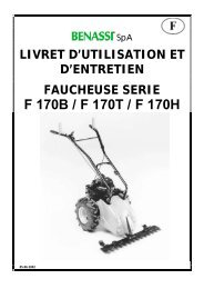
S.p.A.USE AND MAINTENANCE HANDBOOK<strong>MOTORISED</strong> <strong>HOE</strong>MODELBL 4525/11/2002
S.p.A. BL 45INDEX◊◊◊◊◊INTRODUCTIONIDENTIFICATIONS AND TECHNICALSPECIFICATIONSINSTRUCTIONS FOR <strong>MOTORISED</strong> <strong>HOE</strong>ASSEMBLYGENERAL SAFETY REGULATIONSSTARTING AND STOPPING◊◊◊◊◊USE AND ADJUSTMENTSERVICINGTESTS FOR CE REGULATIONSWARRANTYCE CERTIFICATIONINTRODUCTIONDear user,Thank you for preferring BENASSI.The top performance and the easy use of our machine will give you any satisfaction.♦ This machine is the result of a long experience working at the top quality standard and using first quality material.♦ Carefully using and servicing this machine, you will certainly get satisfactory performances for a long time.♦ Please read very carefully this booklet before using your motorised hoe.♦ Pay special attention to the instructions marked out by the following signATTENTION♦ Failure to comply with these instructions may result insidious or even fatal injury.1- Transport wheel2- Tillers3- Tiller protection4- Braking spur5- Belt cover6- Clutch lever forward drive7- Throttle lever8- Clutch lever backward drive9- Handlebar adjustments10- Air filter11- Fuel tank cap12- Choke lever13- Recoil start14- Oil capKEY TO MACHINE PARTS2
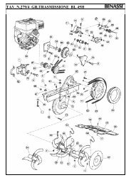
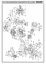
S.p.A. BL 45IDENTIFICATION AND TECHNICAL SPECIFICATIONSModel: BL 45 BNet weight: Kg. 56,2Ploughing version net weight: Kg. 137Engine: 4 tempiEngine: BRIGGS & STRATTON 5,5H5PEngine model: 110492 INTEK/POWERBUILTCc: 190Maximum power BHP:CV: 5,500 (Kw 4,04)R.P.M.: 3.600Model: BL 45 HSNet weight: Kg. 53,5Ploughing version net weight: Kg. 135Engine: 4 tempiEngine: HONDAEngine model: GC 160Cc: 160Maximum power BHP:CV: 5,00 (Kw 3.70)R.P.M.: 3.600Model: BL 45 KNet weight: Kg. 56Ploughing version net weight: Kg. 135Engine: 4 tempiEngine: KAMAEngine model: KG 160Cc: 163 cc.Filtro aria: a bagno d’olioMaximum power BHP:CV: 4,9 (Kw 3.60)R.P.M: 3.600The engines fitted on these cultivators have the following features:• Exhaust guard• Recoil starter• Dry air filter• OIL LUBRICATION WITH: OIL AGIP SIGMA SAE 30• Oil in the oil sump: (see engine’s use and maintenance handbook)• Fuel: white petrol• Safety device for both forward and backward gear stopping the tiller.• The front gear has two speeds. The reverse gear has one speed. The machine has a double belt transmission for the engineand a double greased chain transmission for the tiller.• Higher speed is suggested for milling operations. Reduced speed is suggested for ploughing operations.• Guidance handlebars can be adjusted in many positions (vertical and side adjustment).• The tiller is 81 cm wide.• The frame of the motorhoe is screwed (Pict. 2).• The spur is adjustable (Pict. 3 Ref. “B”)All the identification references (code number, engine, weight, power) are printed on the number plate on the machine. (Picture4 Ref. “D”)APPLICABLE ACCESSORIESWheels with tyres 5.00.10Pair of differential hubsBallasts for wheels 5.00.10 (14 Kg. each one)Front ballast Kg. 24One-bottom plough with attachmentLister with attachmentWheels with tyres 5.00.10 can be changed with iron wheels(Ø 450)Thin iron wheels (Ø 320) are suitable for the use of the lister.-Picture 2- -Picture 3- -Picture 4-INSTRUCTIONS FOR <strong>MOTORISED</strong> <strong>HOE</strong> ASSEMBLYThe machine is packed in a box of the following dimensions:◊◊◊WIDTH: 80 cm.LENGHT: 45 cm.HEIGHT: 70 cm.• Take the machine out of the carton box.• Fit the two tillers to the main shaft using the delivered screws and nuts, assembled on the tillers.• Fit the rear spur in its place using the delivered screw and nut.• Fix the handles to the handlebar support, using parts assembled on the handlebar support.3
S.p.A. BL 45• Insert the forward gear engagement cable, already assembled with the lever on the slot of the handle, and fix the cableadjuster to the internal lever support. Then fix the lever by unscrewing the bolt. Reinsert the screw when the lever is in thesupport, then screw the nut.• Insert the reverse motion engagement cable, already assembled with lever,following the directions above. The cable of the reverse motion lever is the -Picture 5-more external one (see picture 7 ref. H) in the flask of the handlebar, fit thecable lever into the lever support marked “MARCIA INDIETRO”. Therefore,the other lever must be fixed on the support marked “MARCIA AVANTI”; fixthe throttle lever to the internal side of the handlebar, blocking it with the nutassembled on the screw of the throttle lever.• Fix the transport wheel to the frame using two special cotter pins that areassembled on the transport wheel support. The cotter pins must bewithdrawn and inserted again when the wheel is in the wished position on theframe. (Pict. 5 Ref. ”E”).• Fit the two guard-extensions to the main tiller protections fitted on the body of the machine using the proper screws andnuts. The protection guards should reach a width of 60 cm according to the CE.• During the transport the handle can be left unassembled, by means of the threaded bush that fix it to the handlebar support.SECURITY TERMSWARNING: Please, read very carefully this booklet before using your cultivator.Carefully using and servicing this machine, you will certainly get satisfactoryperformances for a long time.FAILURE TO COMPLY WITH THESE INSTRUCTIONS MAY RESULT INSIDIOUS OR EVEN FATALINJURY.• The use of the machine is forbidden to persons younger than 16 years.• The operator is responsible of any possible damage and he should always drive the machine carefully and safety.• Read this booklet before using the machine for the first time.• Before carrying the machine always empty the fuel tank.• Before leaving the machine be sure that it is fully stopped.• Never use the machine without heavy shoes and long transfers. Always inspect the area where you want to work taking offstones, branches, cables and any other thing which can be dangerous.• Before start working, make sure that a radius of minimum 5 mt. is completely free.• Clean any possible leakage of fuel.• Fill up when the engine is off and not hot, always in an open space far from fires or any heating source and refrain fromsmoking during this operation.• Before starting using the machine, make sure that you can quickly stop the engine and that you are familiar with the controllevers.• Never allow the engine to run in enclosed spaces where highly toxic carbon monoxide could not evacuate.• Never start or use the machine not completely assembled, especially concerning the safety devices and the tiller protectionguards which should always be com pletely assembled with all its extensions. Never start hoeing if the belt protection is notassembled.• Never fix or clean the tiller blades or any other tools when the engine is running.• Attention! Don’t use the machine on sloping grounds exceeding the lim it indicated in the use and maintenance booklet ofthe engine..• We are not responsible for accidents due to the wrong use of the machine neglecting the above basic instructions.STARTING AND STOPPING THE MACHINEWhenever you are starting the engine of the machine, follow these instructions very carefully:• Check the oil in the engine : THE BRAND NEW MACHINE IS DELIVERED WITHOUT OIL IN THE ENGINE, THEREFOREYOU SHOULD FILL IT UP TO THE LEVEL ON THE DIP STICK OF THE OIL CUP.• Please read carefully on the booklet the ENGINE USE AND MAINTENANCE concerning the “operations beforestarting”.• Start the engine only in open spaces.1. Pull the choke lever on the engine.2. Turn the accelerator lever “F” to the “MAX” position (Pict. 8) The switch (Ref. “K” Pict.6) must be “ON”.3. The clutch levers “G” and “H” must be out. (Pict. 7) Position “A”.4. Pull the starting rope by the handle “I”, firstly smoothly and then strongly: when you feel some resistance don’t leave thehandle but help the recoiling of the rope with your hand (Pict. 8).5. When the engine runs move the choke lever to the initial position and the accelerator lever in the mid-position (Pict. 6).6. For stopping the engine move the accelerator lever “F” in the “STOP” position (Fig.6) or in the “OFF” position “OFF” (Pict.6 - Ref. “K”).4
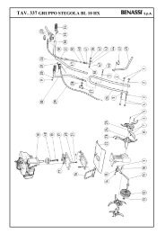
S.p.A. BL 45- Picture 6 - - Picture 7 -- Picture 8 - - Picture 9 - - Picture 10 -USE AND ADJUSTMENT• You can start the rotation of the tiller pulling the clutch lever “G” up to position “b” (Pict. 7) the machine will immediately stopreleasing the lever.• Two speeds are available for this motorhoe going ahead: to change speed, shift the belt after taking off the belt protectioncover by unscrewing 3 knobs. (ref.”T” pict.9). Remember to switch off the engine, before doing this operation.1. The speed of the motorhoe is reduced (R. P. M. 40), when the belt (ref. “U”) is in position “X” (as it’s shown in thepicture 10). Reduced speed is suggested for ploughing operations.2. If you want the motorhoe to go faster, shift the belt (ref. “U”) into the races of the pulleys “Y”, keeping the belt stretcherloose. This speed (R. P. M. 107) is suggested in milling operations.• The reverse motion is engaged by pulling the “H” lever (pict. 7) in “B” position.• Read attentively the following directions, to adjust the tension of the belts.∗ For the high forward speed, keep the gap of about 60-70 mm between the internal sides of the belt on the axis of theguide pulley (see picture 11), keeping the clutch lever engaged .∗ For the reduced forward speed, keep the gap of 55-60 mm between the internal sides of the belts belt on the axis of theguide pulley. (See picture 12)∗ For model BL 45B: keep the gap of 25-35 mm between the internal sides of the belt on the axis of the guide pulley, seepict. 13.• The belt of the front gear is automatically adjusted when the reverse belt is properly adjusted.• If the gap is not correct, you can adjust it by shifting the engine on its guides towards the handlebars if you have to reducethe gap, or viceversa (BL 45 H excluded). After moving the engine (in all models) you should adjust the tension of the beltstretching pulley using the adjusting screws “L” and “M” (Pict. 15), avoiding the belt sliding on the pulley.• Guidance handlebars can be adjusted by unscrewing the blocking lever “P” (pict.16). Adjust the handlebar position as youprefer and then lock it again.• The tiller is 81 cm wide. It’s composed by 3 knives + protection plate, on both sides. It can be reduced to 57 cm, by removingone tiller knife from both sides (see pictures at page 7).• The sharp side of the hoes must be turned to the front side of the machine.• We recommend to use the tiller with the side plates because they improve the stability of the machine and they protect fromplants and any other obstacle.• As optional accessory, the machine can fit an adjustable lister delivered complete with its own support which should be fittedon the rear side of the machine, replacing the standard spur.• This machine can be used for ploughing also at reduced speed. In order to do this you have to assemble two wheel-hubs(pict.17 ref. “P”) in the place of the tillers. Then assemble the wheels with tyres 5.0.10 on the hubs, using the screws. Thewheels are adjustable in 4 track widths.5
S.p.A. BL 45• Fit the tool post in the place of the spur support, fixing it to the handlebar support with the bolt (pict.17 ref. “P”).• Fit the plough on the tool post. The plough can fit three different positions, because the pin (ref “R” pict. 18) can be insertedin three different holes.• The plough can be adjusted by changing the inclination of the blades. Both full side and vertical adjustments are possible bumeans of the tension bar or of both bolts. (ref “V” pict.18).• In doing this kind of work, you have to assemble a ballast in the front of the machine. Fix the ballast in the place of thetransport wheel support (ref “W” pict.19), using two bolts. You have also to assemble two ballasts on the wheels (ref. “X pict.20), using two screws that fix them to the internal side of the wheel rim.CAUTION: IT IS ADVICED NOT TO KEEP THE MOTOR RUNNING WHEN THE MACHIN IS NOT BEING USED FOR ITSSPECIFICAL PURPOSE.- Picture 11 - - Picture 12 - - Picture 13 -HIGH FORWARD SPEED REDUCED FORWARD SPEED REVERSE MOTION BL 45- Picture 14 -(REVERSE MOTION BL 45 HONDA) - Picture 15 - - Picture 16 -- Tillers - - Picture 17 - - Picture 18 -- Picture 19 - - Picture 20 - - Picture 21 -6
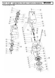
S.p.A. BL 45MAINTENANCE• For the normal maintenance (oil, filter, spark plug) check the booklet for the engine included.• The frame has waterproof ball bearings. The transmission in the frame is engaged by two normal grease-lubricated chains.Every year you should introduce some grease through the hole “Q” (Pict. 21) in the main body.• All the joints, cables and the belt stretcher should be greased from time to time.• Keep the machine and the tillers clean and check that all the screws and nuts are well tied, especially the screws of the tiller(always wear protection gloves working on the tiller).• In case of breaking or wear the belt, you can replace it after taking off the side protection cover by unscrewing 3 knobs fixingthe side protection cover. (Pict. 9)• Take off the belt from the pulleys and install the new belt. After replacing the belt, adjust it to the correct tension following theinstructions in the chapter USE AND ADJUSTMENT.• The pin fixing the big pulley has also a safety purpose: in case of heavy obstacle, it will break avoiding damages to otherparts of the machine.• The replacement of the pin is very easy : you have to insert the new pin in the hole using a hammer. To take off theprotection cover, follow the instructions above.• For any technical repair especially during the guarantee period, it is suggested to apply to the specialised workshops of ourdealers.WARRANTYOur machines and accessories are guaranteed for 12 months excluding electric and rubber parts.All the defective parts will be replaced free of charge excluding cost of labour and transport fees which would be at customer’scharge.For any problem regarding the engine or any other part not of our production please refer to the guarantee conditions stated bythe manufacturer and apply to their assistance centres.For any kind of problem or repair please apply to the dealer where you bought the machine.TESTS FOR CE CERTIFICATIONEC certificate of conformity conforming to directive 98/37/CE and the directive EMC89/336/CE modified 92/31/CE40010 SanMatteo della Decima BO Italy Via Lampedusa n°1 Tel. (051) 820511Declare in sole responsibility that the product CULTIVATOR BL 45 B - BL 45 HS,-BL 45 K to whichthis certificate applies, conforms the basic health and safety requirements stated in the directive 98/37/CE and thedirective EMC 89/336/CE modified 92/31/CEThe laws EN 292-1 - EN 292-2 and EN 709 have been examined to verify this conformity.THE PRESIDENTTEST AND RESULTS.Matteo della Decima, 25/11/2002TYPE MOTOR<strong>HOE</strong> MODEL BL 45 B - BL 45 HS- BL 45 KNoise level at operator’s ear : Laeq = 86 dB (A)Test condition: 1,6 mt at the centre of the handlebarHandlebar vibration according to ISO 1033:value 3,47 m/sec ²7
S.p.A. BL 45S.p.A.VIA LAMPEDUSA 140010 S. MATTEO DELLA DECIMA (BO) - ITALYTEL. 0039/051/82.05.34 TELEFAX 0039/051/682.61.64e-mail: export@benassispa.itwww.benassispa.itDealer stamp8