AC and DC Variable Speed Drives Application ... - Reliance Electric
AC and DC Variable Speed Drives Application ... - Reliance Electric
AC and DC Variable Speed Drives Application ... - Reliance Electric

You also want an ePaper? Increase the reach of your titles
YUMPU automatically turns print PDFs into web optimized ePapers that Google loves.
������������������������<br />
������������������<br />
��������������<br />
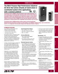
Introduction <strong>Application</strong> Discussion<br />
Knowing what controller/motor package to use in a given situation<br />
is just one of the subjects covered in this overview of <strong>AC</strong> <strong>and</strong> <strong>DC</strong><br />
drive application considerations. Published originally as a direct<br />
mail piece for distribution use, it has been updated with additional<br />
information on drive selection to make it a more useful reference<br />
<strong>and</strong> training tool. This has been previously released as publication<br />
D-7151, but is updated here.<br />
This information also appears in the introduction section of the<br />
St<strong>and</strong>ard <strong>Drives</strong> Catalog (D-406).<br />
Drive products support diverse applications with a wide variety of<br />
products. <strong>AC</strong> drives serve processing needs <strong>and</strong> industrial applications<br />
such as fans, pumps, mixers, conveyors, <strong>and</strong> extruders,<br />
plus many more. <strong>DC</strong> drives control processing equipment such as<br />
for sheet metal, material h<strong>and</strong>ling, <strong>and</strong> center winders/unwinders.<br />
Any drive featured in this publication will provide some form of<br />
motor speed regulation <strong>and</strong> variable speed operation. Within<br />
these categories, we offer a broad spectrum of horsepower<br />
ranges, drive interconnectivity capabilities, <strong>and</strong> flexibilities.<br />
When selecting a drive for your application, a major consideration<br />
is whether to use an <strong>AC</strong> or <strong>DC</strong> drive. Either drive is practical from<br />
the following st<strong>and</strong>points:<br />
• Wide constant horsepower speed range<br />
• Proven performance with matched drive/motor packages<br />
• High speed regulation capabilities<br />
• Worldwide sales <strong>and</strong> technical support<br />
The considerations involved in choosing either <strong>AC</strong> or <strong>DC</strong> drives are<br />
discussed in the following section.<br />
<strong>Application</strong> Solution<br />
Which drive is right for you?<br />
Your choice depends on many application-specific factors such as<br />
ambient conditions, type of loads, duty cycle, maintenance<br />
accessibility, horsepower range, sequencing, <strong>and</strong> more. The<br />
following brief guidelines have been developed to provide you<br />
with a basic underst<strong>and</strong>ing of the differences between <strong>AC</strong> <strong>and</strong> <strong>DC</strong><br />
drive technologies. If you have specific questions, or require<br />
application/selection assistance, please contact your nearest<br />
<strong>Reliance</strong> <strong>Electric</strong> Sales Office or authorized <strong>Reliance</strong> Distributor.<br />
<strong>AC</strong> DRIVE CHAR<strong>AC</strong>TERISTICS<br />
• <strong>AC</strong> drives utilize a solid-state adjustable frequency inverter<br />
which adjusts frequency <strong>and</strong> voltage for varying the speed of an<br />
otherwise, conventional fixed speed <strong>AC</strong> motor. This is achieved<br />
through Pulse-Width Modulation (PWM) of the drive output to<br />
the motors.<br />
• Voltage <strong>and</strong> frequency are maintained at a constant relationship<br />
at any motor speed to maintain a constant torque. This is<br />
known as the volts per hertz ratio.<br />
• Integrated drive/motor packages available.<br />
St<strong>and</strong>ard <strong>AC</strong> <strong>Drives</strong> are often the best choice when:<br />
• The environment surrounding the <strong>AC</strong> motor is corrosive,<br />
potentially explosive, or very wet, <strong>and</strong> dem<strong>and</strong>s special<br />
enclosures such as explosion-proof, washdown, X-Extra Tough,<br />
etc.<br />
• Motors are likely to receive little regular maintenance due to<br />
inaccessibility of the motor or poor maintenance practices.<br />
• The motor must be small in size <strong>and</strong> weigh as little as possible.
• Motor speeds can reach 10,000 RPM.<br />
• Multiple motors are operated at the same speed by a single<br />
drive.<br />
• <strong>Speed</strong> regulation of 1 % is acceptable.<br />
• Existing fixed speed (Design B) <strong>AC</strong> motors can possibly be used.<br />
• A UL listed <strong>AC</strong> drive <strong>and</strong> motor package for hazardous<br />
classified locations is required.<br />
• C-E compliance is required at 2 HP or less.<br />
Additionally, Vector <strong>AC</strong> <strong>Drives</strong> are often the best choice<br />
for:<br />
• <strong>Application</strong>s requiring full load torque at zero speed.<br />
• Fast changing loads.<br />
• Tight speed regulation.<br />
• Coordinated speed control for multiple drive axes.<br />
• <strong>Application</strong>s requiring increased starting torque.<br />
• Precise closed loop speed regulation (to 0.01% <strong>and</strong> less) is<br />
required.<br />
• High dynamic response.<br />
• Web processes, material h<strong>and</strong>ling sorter conveyors, metering<br />
pumps, extruders, <strong>and</strong> test st<strong>and</strong>s.<br />
<strong>DC</strong> DRIVE CHAR<strong>AC</strong>TERISTICS<br />
• <strong>DC</strong> drives utilize a converter to transform <strong>AC</strong> current into <strong>DC</strong><br />
current which is then fed to the <strong>DC</strong> motor which is designed for<br />
adjustable speed operation. <strong>Speed</strong> changes are made by<br />
increasing or decreasing the amount of <strong>DC</strong> voltage fed to the<br />
motor from the drive.<br />
• Usually offer the lowest cost for medium <strong>and</strong> high HP<br />
applications.<br />
<strong>DC</strong> <strong>Drives</strong> are often the best choice when:<br />
• Environmental conditions surrounding the <strong>DC</strong> motor are<br />
reasonably clean, dry, <strong>and</strong> allow the use of DPG, DPG-FV, TENV,<br />
or TEFC motor enclosures.<br />
• The application requires a wide range of changing loads such<br />
as center driven winders.<br />
• Motor speeds can reach 2500 RPM.<br />
• Starting torques are greater than 150% or unpredictable.<br />
• <strong>Application</strong> HP requirements are medium to large.<br />
Drive Comparison Chart<br />
Use this chart as a quick, basic reference guide to help you<br />
determine the drive best suited for your application needs.<br />
<strong>Speed</strong> Regulation<br />
<strong>Speed</strong> Range<br />
Encoder/Tachometer Required?<br />
Constant HP Range<br />
Starting Torque<br />
High-<strong>Speed</strong> Capability (1)<br />
Regeneration<br />
Dynamic Braking w/o Regulation<br />
St<strong>and</strong>ard<br />
<strong>DC</strong><br />
0.01% (2)<br />
100:1<br />
Yes/No<br />
4:1<br />
150%<br />
need to be a motor specifically designed for <strong>AC</strong> drive operation<br />
such as the RPM <strong>AC</strong> motor. RPM <strong>AC</strong> motors offer premium performance<br />
on <strong>Reliance</strong> <strong>AC</strong> drives<br />
SIZING THE <strong>AC</strong> MOTOR<br />
The following procedure gives a conservative, engineering-based<br />
approach for sizing <strong>and</strong> selecting various <strong>AC</strong> motors for use with<br />
the <strong>AC</strong> drive.<br />
WARNING<br />
M<strong>AC</strong>HINERY BUILDERS AND/OR USERS ARE RESPONSIBLE FOR<br />
INSURING THAT ALL DRIVE TRAIN MECHANISMS, THE DRIVEN<br />
M<strong>AC</strong>HINE, AND PROCESS MATERIAL ARE CAPABLE OF SAFE<br />
OPERATION AT THE MAXIMUM SPEED AT WHICH THE M<strong>AC</strong>HINE<br />
WILL OPERATE. FAILURE TO OBSERVE THESE PRECAUTIONS<br />
COULD RESULT IN BODILY INJURY.<br />
1. Determine the drive motor output horsepower <strong>and</strong> continuous<br />
torque over the total speed range <strong>and</strong> the starting torque<br />
requirements.<br />
2. Select the type of motor <strong>and</strong> drive.<br />
3. Using the following graphs for the type of motor selected,<br />
confirm that the required load torque from the motor selected<br />
falls within the "acceptable region" of the graph.<br />
GRAPHS 1 THROUGH 4 SHOW TYPICAL CONSTANT TORQUE<br />
SPEED RANGE CURVES WITH GENERAL PURPOSE REGULATION -<br />
GV3000/SE (With Parameter P.048 Set For"U-H") AND SP500.<br />
GRAPHS 1 AND 2 ARE ALSO TYPICAL FOR BOTH THE SP100 AND<br />
SP200 DRIVES.<br />
Continuous motor performance for constant torque to base speed<br />
<strong>and</strong> constant horsepower above base speed. Wider constant<br />
torque ranges <strong>and</strong>/or horsepowers are available but application<br />
assistance will be required.<br />
Graph 1. 10:1 CONSTANT TORQUE<br />
This graph applies for the following motors used with an <strong>AC</strong><br />
PWM drive:<br />
• VXS vector-ready motors to 10 HP.<br />
• VXS inverter duty motors to 150 HP.<br />
• Explosion-proof energy efficient XE motors 1/3-150 HP (check<br />
motor nameplate to verify CT rating).<br />
• TENV-EM <strong>and</strong> TENV EMT motors (for use with SP100 drives).<br />
Graph 2. 4.1 CONSTANT TORQUE<br />
This graph applies for the following motors used with an <strong>AC</strong><br />
PWM drive:<br />
• TENV <strong>and</strong> TEFC energy <strong>and</strong> premium efficient motors 1-350 HP.<br />
• TENV-EZ easy-clean washdown duty motors.<br />
• Explosion proof energy-efficient XE motors 11/2 - 150 HP<br />
(check motor nameplate to verify CT ratio).
Graph 3. 2:1 CONSTANT TORQUE<br />
For use with explosion-proof energy efficient XE motors 11/2 - 150<br />
HP (check motor nameplate to verify CT ratio).<br />
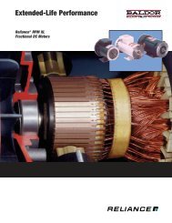
Graph 4. <strong>Reliance</strong> RPM <strong>AC</strong> Motors (TENV, TEA0-BC <strong>and</strong><br />
DPFV Enclosures) <strong>and</strong> VSM500 Integrated Drive/Motor<br />
Packages<br />
Graph 5. <strong>Reliance</strong> Vector Duty Induction Motors (TENV,<br />
TEA0-BC <strong>and</strong> DPG-FV Enclosures) with Encoder Feedback<br />
SIZING THE <strong>AC</strong> DRIVE<br />
The capabilities of the <strong>AC</strong> drive are determined by its output current<br />
rating. The drive chosen must have a continuous current rating<br />
equal to or more than the maximum motor load current. Be<br />
sure to consider all loads including startup acceleration.<br />
Single Motor <strong>and</strong> Drive <strong>Application</strong>s<br />
NEMA Design B motors, will generally perform as shown in the<br />
engineering data section. Note that all references to HP are for<br />
single motor, st<strong>and</strong>ard NEMA B, 1.0 service factor, non-explosion<br />
proof induction motors only.<br />
General Sizing Method for Use with Multiple Induction<br />
Motors<br />
To size the six to 60 Hz drive for multiple motor applications or for<br />
any applications for six to 120 Hz, the following procedure is used.<br />
1. Examine each motor to be driven <strong>and</strong> determine motor full-load<br />
amperes at line voltage. Determine the total full-load current<br />
requirements for all motor(s) to be controlled by the drive.<br />
2.To the current determined in step one, add the high currents of<br />
any overloads which may exist such as acceleration, peak load,<br />
etc., - <strong>and</strong> determine maximum short-term load at line voltage.<br />
(Note: motor acceleration is by linear timed-rate acceleration<br />
control. Therefore, locked-rotor amperes normally associated<br />
with across-the-line starting of <strong>AC</strong> motors are not<br />
encountered.)<br />
3. Select the <strong>AC</strong> drive rating from the table with a current
capacity that will support the required currents as calculated in<br />
the previous steps.<br />
4. If other than NEMA Design B - 1.0 Service Factor Induction<br />
motors are to be used, or if explosion proof listed motors are<br />
required contact your <strong>Reliance</strong> <strong>Electric</strong> sales office or St<strong>and</strong>ard<br />
<strong>Drives</strong> application engineer for application assistance.<br />
<strong>AC</strong> DRIVE LEAD LENGTH<br />
St<strong>and</strong>ard <strong>AC</strong> drives utilize IGBT technology for rapid switching of<br />
PWM devices to produce accurate sinusoidal drive outputs.<br />
Typically operating at carrier frequencies of 8 kHz, low motor<br />
acoustic noise is achieved. However, PWM devices can also<br />
cause undesirable side effects such as motor stress, high peak<br />
voltage <strong>and</strong> possible reflected waves that exacerbate the peak<br />
voltage problems.<br />
<strong>Reliance</strong> <strong>Electric</strong>'s matching drive/motor packages offer superior<br />
design <strong>and</strong> proven performance. All drive/motor combinations<br />
have been tested for dynamic stability. When applied properly,<br />
motor stress effects <strong>and</strong> high peak voltage should be minimal.<br />
The table below highlights maximum motor lead lengths allowed<br />
without external filtering.<br />
Maximum Lead Length* (Feet)<br />
GV3000/SE<br />
SP500<br />
SP200<br />
230V<strong>AC</strong> 460V<strong>AC</strong> 575V<strong>AC</strong><br />
500<br />
500<br />
100<br />
500<br />
250<br />
100<br />
N/A<br />
150<br />
N/A<br />
*Maximum lead lengths vary also with carrier frequencies <strong>and</strong><br />
horsepower ratings. Additional external filters can be specified<br />
to extend lead lengths. Please see <strong>Application</strong> Note D-154 for<br />
more detailed information.<br />
Open loop <strong>AC</strong> PWM Control Block Diagram<br />
A. The user supplies a speed reference to the drive. There is<br />
always a choice between supplying a remote analog<br />
reference or a local reference via keypad selection.<br />
B. The speed reference may be conditioned for acceleration <strong>and</strong><br />
deceleration rates as well as maximum <strong>and</strong> minimum speed<br />
settings.<br />
Open Loop <strong>AC</strong> PWM Control Block Diagram<br />
�����<br />
���������<br />
������<br />
������<br />
�����<br />
�����������<br />
�����<br />
������<br />
������ �����<br />
���������<br />
����<br />
������<br />
�������<br />
��������<br />
���������<br />
���<br />
��������<br />
��<br />
�����<br />
�������������<br />
* Can be single phase input depending upon the type of drive<br />
selected.<br />
C. The speed regulator section provides gate pulses to the<br />
continually alternating Insulated Gate Bipolar Transistors<br />
(IGBTs). The relative on-to-off times for pulses to be successively<br />
fired is continually alternating so as to create a sinusoidal<br />
voltage pattern at the IGBT output. The wave frequency is<br />
altered to produce variable speed outputs.<br />
D. Rectified <strong>DC</strong> voltage (or <strong>DC</strong> bus supply voltage) is the source for<br />
the IGBTs. They are arranged in three pairs whose wave patterns<br />
are each 120 degrees apart. The power output signals to the<br />
motor create sinusoidal wave patterns to each phase. Wave<br />
frequency changes to change the motor's speed.<br />
<strong>AC</strong> PWM Vector Control Block Diagram<br />
Remote<br />
Signal<br />
+<br />
<strong>Speed</strong><br />
Reference<br />
Scale<br />
-<br />
Local<br />
Signal<br />
<strong>Speed</strong><br />
Loop<br />
Field<br />
Controller<br />
<strong>Speed</strong><br />
Feedback<br />
Compare<br />
GT<br />
Limits<br />
Torque<br />
Comm<strong>and</strong><br />
Flux<br />
Comm<strong>and</strong><br />
d<br />
dt<br />
Vector<br />
Torque<br />
Controller<br />
Gate<br />
Signal<br />
Rotor<br />
Postion<br />
Current<br />
Feedback<br />
��������������<br />
<strong>AC</strong> Line<br />
Input<br />
Rectifier<br />
PWM Inverter<br />
<strong>AC</strong><br />
Motor<br />
<strong>AC</strong> PWM VECTOR Control Block Diagram<br />
A. The user supplies a speed reference to the drive. There is<br />
always a choice among supplying a remote analog reference or<br />
������<br />
Differential<br />
Encoder
local reference via keypad selection. Also, it could be supplied<br />
across a network interface if an optional network interface card<br />
is included with the drive.<br />
B. The speed reference may be conditioned for acceleration <strong>and</strong><br />
deceleration rates as well as maximum <strong>and</strong> minimum speed<br />
settings.<br />
C. The conditioned speed reference is compared to a speed feed<br />
back signal as supplied by the motor encoder. Any error signal<br />
between the reference <strong>and</strong> the feedback signal is amplified in<br />
this outer (or major) control loop via proportional <strong>and</strong> integral<br />
gains. Stability adjustments change the gain of this control loop<br />
to match the desired dynamic response. The resulting signal is<br />
applied as a reference to the current regulator. Motor current<br />
will provide torque, which will in turn change the motor speed<br />
to satisfy this outer loop, driving its error to zero.<br />
D. This inner current control loop receives a reference from the<br />
speed loop. This reference is compared to current feedback<br />
from the motor. Any error is amplified <strong>and</strong> used to change the<br />
relative on <strong>and</strong> off times for gate pulses to the continually<br />
alternating Insulated Gate Bipolar Transistors (IGBTs). The<br />
relative on-to-off times for pulses to be successively fired is<br />
continually alternating so as to create a sinusoidal voltage<br />
pattern at the IGBT output. The wave frequency <strong>and</strong> its<br />
amplitude are altered to respectively produce variable speed<br />
<strong>and</strong> torque outputs.<br />
E. As an alternative, vector operation without encoder feedback,<br />
called sensorless vector mode, is also available <strong>and</strong> discussed<br />
below.<br />
F. Rectified <strong>DC</strong> voltage (or <strong>DC</strong> bus supply voltage) is the source for<br />
the IGBTs. They are arranged in three pairs whose wave patterns<br />
are each 120 degrees apart. The power output signals to the<br />
motor create sinusoidal wave patterns to each phase. Wave<br />
frequency changes to change the motor's speed.<br />
G. Vector drives provide a way to regulate field supply voltage or<br />
current. These drives have the capability to limit the flux or<br />
field comm<strong>and</strong> <strong>and</strong> effect a field weakening condition to allow<br />
extended speed operation. This can be seen as the optional <strong>AC</strong><br />
drive operating range in the motor speed-torque curves.<br />
Sensorless vector operation, which is used to achieve dynamic<br />
speed <strong>and</strong> torque <strong>and</strong> control without a speed feedback device,<br />
works as follows.<br />
A. The current feedback from a motor can be broken into its<br />
components: magnetizing <strong>and</strong> torque producing currents.<br />
Picture these as the legs of a right triangle, with the actual or<br />
measured current as the hypotenuse.<br />
B. The magnetizing current can be shown as equivalent to the<br />
motor's no-load current. (Less windage <strong>and</strong> friction losses).<br />
This is a function of the motor's rotor design <strong>and</strong> is constant.<br />
C. The torque producing current can be measured based on<br />
knowing item B. Furthermore, it can be demonstrated that<br />
motor slip <strong>and</strong> torque are related. This means that a particular<br />
load current measurement at a given comm<strong>and</strong>ed speed will be<br />
used to calculate the motor's slip at that moment. This will<br />
provide an accurate determination of actual motor speed.<br />
D. Based on the actual vs. desired speed, the reference is<br />
continually adjusted to get the proper speed given the<br />
calculated slip.<br />
E. This method of control will provide speed regulation to 0.5%<br />
on a steady state basis. Operation at or near zero speed is<br />
possible, but accuracy falls off because slip measurement at<br />
low frequencies becomes more difficult to measure.<br />
For further reading on the basics of operation of vector control,<br />
please refer to D-7161, Vector Operation Basics.<br />
How A Phase Controlled <strong>DC</strong> Drive Works<br />
* If drive is equipped with motor field control hardware or<br />
software.<br />
** If motor has a wound field (not permanent magnet).<br />
Items A-I in this block diagram illustrate the basic functional<br />
blocks of a <strong>DC</strong> drive.
A. The user supplies a speed comm<strong>and</strong> to the drive.<br />
B. The speed reference may be conditioned for acceleration <strong>and</strong><br />
deceleration rate, as well as maximum <strong>and</strong> minimum speed<br />
settings.<br />
C. The conditioned speed reference is compared to the voltage<br />
(voltage regulator) or speed (speed regulator using a<br />
tachometer) feedback signal from the motor. Any error<br />
between the reference <strong>and</strong> feedback is amplified in this outer<br />
(or "major") control loop <strong>and</strong> applied as a reference to the<br />
current regulator. Motor current will provide torque which will<br />
in turn change the motor voltage <strong>and</strong>/or speed to satisfy this<br />
outer loop, driving its error to zero. Stability adjustments<br />
change the gain of this control loop to match the desired<br />
dynamic response of the motor <strong>and</strong> load.<br />
D. This inner (or "minor") current control loop receives a reference<br />
from the speed or voltage outer loop. This reference is<br />
compared to current feedback from the motor. Any error is<br />
amplified <strong>and</strong> used to change the thyristors' firing angle. This<br />
causes a change in current flow in the motor to satisfy the<br />
current loop, driving its error to zero. Some drives permit<br />
stability adjustments which change the gain of this control loop<br />
to match the electrical characteristics of the motor armature.<br />
The inner current loop provides smooth drive performance <strong>and</strong><br />
current limit capability.<br />
E. The driver section of the regulator provides gate pulses to the<br />
thyristors that are synchronized to the power line phasing. The<br />
firing angle of the thyristors is determined from the current<br />
loop output <strong>and</strong> operating conditions such as the counter EMF<br />
of the armature.<br />
F. The <strong>AC</strong> line power is converted to <strong>DC</strong> by the rectifiers in the<br />
power bridge. Phase controlled drives have some complement<br />
of thyristors, <strong>and</strong> sometimes diodes, depending on the type of<br />
bridge.<br />
G. Some drives provide a way to regulate field supply voltage or<br />
current. These drives have regulator functionality to<br />
accomplish this.<br />
H. <strong>DC</strong> motor armature.<br />
I. Tachometer or encoder if supplied.<br />
Field Supply Bridge Types<br />
���<br />
<strong>DC</strong> MOTOR TYPES<br />
The following section provides descriptions of the three most<br />
common types of <strong>DC</strong> motors used with <strong>Reliance</strong> <strong>DC</strong> <strong>Drives</strong>.<br />
����<br />
������������<br />
��������<br />
���� �������������<br />
� �� � ���<br />
�����������<br />
��������<br />
���� ������<br />
��� ���<br />
� ��<br />
� ��<br />
Permanent Magnet <strong>DC</strong> Motor<br />
Permanent magnet motors have a conventional wound armature<br />
with commutator, brushes, <strong>and</strong> a permanent magnet field. This<br />
motor has excellent starting torques but speed regulation is less<br />
accurate than for compound motors. However, the speed regulation<br />
can be improved with various designs, such as corresponding<br />
lower rated torques for a given frame. Because of the permanent<br />
����<br />
� ���<br />
������������<br />
���������<br />
���� �� ���� ������<br />
�����������<br />
�������<br />
���� �� �����<br />
������
field, motor losses are less with better operating efficiencies.<br />
These motors can be dynamically braked <strong>and</strong> reversed at reduced<br />
armature voltage (10%) but should not be plug reversed with full<br />
armature voltage. Reversing current cannot exceed the full load<br />
armature current.<br />
Straight Shunt Wound <strong>DC</strong> Motor<br />
Shunt wound motors with the armature shunted across the field<br />
offer relatively flat speed-torque characteristics. Combined with<br />
inherently controlled no-load speed, this provides good speed regulation<br />
over wide load ranges. While the starting torque is comparatively<br />
lower than the other <strong>DC</strong> winding types, shunt wound<br />
motors offer simplified control for reversing <strong>and</strong> regenerative<br />
service.<br />
Stabilized Shunt Wound <strong>DC</strong> Motor<br />
Reach us now at www.rockwellautomation.com<br />
Wherever you need us, Rockwell Automation brings together leading<br />
br<strong>and</strong>s in industrial automation including Allen-Bradley controls,<br />
<strong>Reliance</strong> <strong>Electric</strong> power transmission products, Dodge mechanical power<br />
transmission components, <strong>and</strong> Rockwell Software. Rockwell Automation’s<br />
unique, flexible approach to helping customers achieve a competitive<br />
advantage is supported by thous<strong>and</strong>s of authorized partners, distributors<br />
<strong>and</strong> system integrators around the world.<br />
Americas Headquarters, 1201 South Second Street, Milwaukee, WI 53204, USA, Tel: (1) 414 382-2000, Fax: (1) 414 382 4444<br />
European Headquarters SA/NV, avenue Herrmann Debroux, 46, 1160 Brussels, Belgium, Tel: (32) 2 663 06 00, Fax: (32) 2 663 06 40<br />
Asia Pacific Headquarters, 27/F Citicorp Centre, 18 Whitfield Road, Causeway Bay, Hong Kong, Tel: (852) 2887 4788, Fax: (852) 2508 1846<br />
<strong>Reliance</strong> <strong>Electric</strong> St<strong>and</strong>ard <strong>Drives</strong> Business, 24800 Tungsten Road, Clevel<strong>and</strong>, OH 44117, USA, Tel: (1) 888 374 8370, Fax: (216) 266 7095<br />
Stabilized shunt motors utilize a field winding in series with the<br />
armature in addition to the shunt field to obtain a compromise in<br />
performance between a series <strong>and</strong> shunt type motor. This type<br />
offers a combination of good starting torque <strong>and</strong> feed stability.<br />
Approximate constant torque speed ranges of <strong>Reliance</strong> <strong>DC</strong> motors<br />
used with <strong>Reliance</strong> <strong>DC</strong> drive controllers.<br />
EnclosureConstant Torque <strong>Speed</strong> Range<br />
DPG 60-100%<br />
DPFV 1-100%<br />
DPSV 1-100%<br />
TENV 5-100%<br />
TEFC 60-100%<br />
TEAO 5-100%<br />
TEA<strong>AC</strong> 5-100%<br />
TEW<strong>AC</strong> 5-100%<br />
<strong>DC</strong> Motor Full Load Operating Characteristic<br />
NOTE: This material is not intended to provide operational instructions. Appropriate <strong>Reliance</strong><br />
<strong>Electric</strong> <strong>Drives</strong> instruction manuals precautions should be studied prior to installation,<br />
operation, or maintenance of equipment.<br />
Publication D-7725 – March 2000 © 2000 Rockwell International Corporation All Rights Reserved Printed in USA