MA Series part 1 - Coffing Hoists, Coffing Hoist Parts
MA Series part 1 - Coffing Hoists, Coffing Hoist Parts
MA Series part 1 - Coffing Hoists, Coffing Hoist Parts
- No tags were found...

Create successful ePaper yourself
Turn your PDF publications into a flip-book with our unique Google optimized e-Paper software.
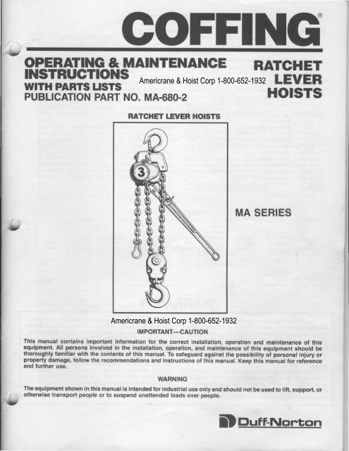
vCOFFINGOPERATING & <strong>MA</strong>INTENANCEINSTRUGTIONSWITI{ PARTS LISTSPUBLICATION PART NO. <strong>MA</strong>.68O-2Americrane & <strong>Hoist</strong> Corp 1-800-652-1932RATCHETLEVERHOISTSRATCHET LEVER HOISTSt<strong>MA</strong> SERIESAmericrane & <strong>Hoist</strong> Corp 1-800-652-1932IMPORTANT_CAUTIONThis manual contains important information for the correct installation, operation and maintenance of thisequipment. All persons involved in the installation, operation, and maintenince of this equipment should bethoroughly familiar with the contents of this manual. To safeguard againsthe possibility oi personal injury orproperty damage, follow the recommendations and instructions of this manual. Keep this mahual for refirehceand further use.UWARNINGThe equipment shown in this manual is intended for industrial use only and should not be used to lift, support, orotherwise transport people or to suspend unattended loads over people.DDuff-Nonron
SECTION I1-11-31-5SECTION II2-l2-42-6SECTION III OPERATION .3-1 Safety Considerations3-3 OperationSECTION IV4-L4-34-54-74-94-114-134-2L4-234-25SECTION V5-1INTRODUCTION.General Information .<strong>Hoist</strong> ConstructionLeading Particulars.Inspection PriInstallationTesting.PREPARATION FOR USEor to Initial UseTAETE OF CONTENTS<strong>MA</strong>INTENANCE .6Inspections6Frequent Inspections6Periodic Inspections6Inspection of <strong><strong>Hoist</strong>s</strong> Not in Regular Use7Checking Chain for Wear7Lubrication7DisassemblvoCleaning. .l2lnspections for Excessive Wear . . . 13Assemblyl3ILLUSTRATED PARTS LISTl7General .t733334444444Americrane & <strong>Hoist</strong> Corp 1-800-652-1932WARRANTYEvery hoist is thoroughly inspected and tested prior modifications or alterations made by persons other thanto shipmeht from the factory. Should any problems develop,return the complete hoist prepaid to your nearest personnel; (3) the hoisl has been abused or damaged asfactory or Duff-Norton Authorized Warranty Repair StalionDuff-Norton Authorized Warranty Repair Station. lf a result of an accident; (4) repair <strong>part</strong>s or accessoriesinspection reveals that the problem is caused by defective other than those supplied by Duff-Norton Company areworkmanshipmaterial, repairs will be made without used on the hoist. Equipment and accessories not of thecharge and the hoist will be returned, transportation seller's manufacture are warranted only to the extenthatprepaid.they are warranted by the manufacturer. EXCEPT ASThis warranty does not apply where: (1) deterioration STATED HEREIN, DUFF.NORTON COMPANY <strong>MA</strong>KESis caused by normal wear, abuse, improper or inadequate NO OTHER WARRANTIES, EXPRESS OR IMPLIED,power supply, eccentric or side loading, overloading, INCLUDING WARRANTIES OF MERCHANTABILIWchemical or abrasive aclions, improper maintenanoe or AND FITNESS FOR A PARTICUI.AR PURPOSE.excessive heat; (2) problems resulted from repairs,
sEcTroN IINTRODUCTION Americrane & <strong>Hoist</strong> Corp 1-800-652-1932U1-1. GENERAL INFOR<strong>MA</strong>TION.1-2. This manual provides information for personsengaged in the operation and maintenance of a <strong>Coffing</strong><strong>MA</strong> Ratchet Lever <strong>Hoist</strong>. All persons operating ormaintaining a model <strong>MA</strong> hoist must be familiar withthe information contained herein. Adherance to theprecautions, procedures and maintenance practicesdescribed herein should ensure long and satisfactoryuse of your hoist with minimum danger to life, limband property. If any operating or maintenance informationherein seems inadequate for your <strong>part</strong>icularproblem please call or write our service engineers. Wesolicit your suggestions for improvements to thismanual.Note: The information herein is directed to the properuse, care and maintenance of the <strong>MA</strong> <strong>Hoist</strong> and doesnot comprise a handbook on the broad subject ofrigging. Rigging can be defined as the process oflifting and moving heavy loads using hoists and othermechanical equipment. Skill acquired through specializedexperience and study is essential to safe riggingoperations. For rigging information, we recommendconsuiting a standard textbook on the subject.1-3. HO|ST CONSTRUCTTON.1-4. The body and handle of the <strong>MA</strong> hoist are madeof aluminum alloy for strength without excess weight.The hoist unit is protected from load slippage becausethe brake mechanism is sealed against the entrance ofoil, chemicals and dirt-all common causes of hoistslippage. Five seals keep the brake clean and dry,assuring constant brake performance even under conditionsof exposure. Long service life is assured by theheat-treated load sheave and high tensile, heat-treatedsteel link chain. High quality self-lubricating bushingsare used to reduce wear. The handle is secured to thehoist with a cap screw and retainer cap, not a snapring.1-6. This manual covers eight hoists that comprisethe <strong>MA</strong> series. They are: Models <strong>MA</strong>-1.5, <strong>MA</strong>-15-2,<strong>MA</strong>-15-2W, <strong>MA</strong>-30, <strong>MA</strong>-30-2, <strong>MA</strong>-30-2W, <strong>MA</strong>-30-3and <strong>MA</strong>-30-4.1-7. The operator should be aware of the capabilitiesof his hoist. He must refrain from overloading. Overloadingnot only can cause damage to the hoist, butpresents serious threats to persons around the hoist.See Table I for some leading <strong>part</strong>iculars with whichthe operator should be familiar.tModelNoRstedCapacity(hunds)StandardLiftOnches)TABLE I. LEADING PARTICULARSAv. Pullon Irverto LiftFull Inad(Founds)Approx.Net Wt.(Founds)Min.DistanceBetweenHooks0nches)kverI.ength(Inches)Min. Incr.in LiftingFositionOnches)Numberof(Chains)<strong>MA</strong>-I5 1,500 60 6l l4t/o t2% 20y, .188 I<strong>MA</strong>-15-2 3,000 60 6t 20Yo t'l 20y, .094 2<strong>MA</strong>-15-2W 3,000 60 60 20 l5 20Y, .094 ,<strong>MA</strong>-30 3,000 60 82 23 l5 20/, .088 I<strong>MA</strong>-30-2 6,000 60 87 36 t8% 20/, .w 2<strong>MA</strong>-30-2W 6,000 60 87 36 t8% 20y, ,w 2<strong>MA</strong>-30-3 9,000 60 90 53 23Yt 20y, .029 3<strong>MA</strong>-30-4 12,000 60 93 63 22 20y, .022 4Americrane & <strong>Hoist</strong> Corp 1-800-652-1932t
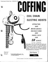
2_1. INSPECTION PRIOR TO INITIAL USE.2-2. Any new or repaired hoist, as well as the workingarea, shall be carefully inspected prior to initialinstallation and use. The inspection shall be made byor under the direction of a person familiar with hoistoperations and industrial safety standards.2-3. The following inspection criteria are recommendedprior to initial installation and use. Additionalinspection items should be added to satisfy localusage and safety requirements. All inspections of anykind should be logged or recorded, dated, signed andfiled for reference purposes.a. Ensure that the supporting structures arestrong enough to carry the intended loads. The supportingstructure shall have a safe load rating at leastequal to that of the hoist. The supporting structuremust be rigid and not subject to weakening due torepeated stresses from the hoistb. Ensure that there is adequate working spaceto permit hoist operation. Normal operation should notrequire pulling or tugging around corners or obstructions.Also, there must be adequate space to permitthe operator and other persons to stand clear of theload and adjacent structures.sEcTroN tlPREPARATION FOR USEc. Watch out for makeshift or compromisingpractices either during installation or subsequentoperation of the hoist. Sometimes the "temporary" fixremains until an accident occurs.d. Perform both the frequent and the periodicinspections specified herein on a repaired hoist priorto initial use. Perform the frequent inspections specifiedherein on a new hoist prior to initial use.2-4. INSTALLATION.2-5. Secure the hoist to a suitable supporting memberby use of the top hook. Make sure that the hook latchis closed. Apply a small amount of lubriplate or equivalentbetween the hook and supporting member.2-6. TESTING.2-7. Check the hoist through a few lifting and loweringcycles with no load o4 the hook. Attach a loadof fifty pounds to the hook and check the hoist througha few lifting and lowering cycles. Check for loaddrift. If brake operation is normal with this light load,test the hoist for operation with the rated load, andthen with about 125 percent ol the rated load. Thehoist should operate smoothly and the brake shouldprevent load drift.Americrane & <strong>Hoist</strong> Corp 1-800-652-1932sEcTloN lllOPERATION3-1. SAFETY CONSIDERATIONS.3-2. This hoist is designed for proper operationwithin the limits of its rated capacity. The hoist hasfeatures designed to minimize the potential for injurydue to failure of the hoist itself. However, here aresome additional pointers which should be followed inorder to ensure proper operation.a. Do not overload the hoist.b. Do not use a handle extender (cheater bar).The hoist is designed to lift or pull its rated capacitywhen a reasonable effort is applied to the end of thehandle by one person (see table I). If effort appears tobe excessive recheck the load and use a larger capacityhoist if necessary.c. Do not side load the hoist. Always pull in astraight line between hooks. Side loading over a sharpcorner may fracture the hoist housing or load block.d. Be sure there are no twists in the loadchain.e. Do not operate the hoist from an off balanceposition. Operator should have firm footing or beotherwise secured before operating the hoist.f. Before raising or pulling a load, alwayscheck to see that it is held securely in the hook orsling, etc. Raise or pull the load only until the loadchain is taut and then recheck the rigging beforecontinuing to raise the load.g. Make sure that the slings and other rigginghave sufficient capacity to support the load, and arein good condition.h. STAND CLEAR OF THE LOAD AT ALLTIMES. Do not move a load in such a manner as toendanger personnel.i. Do not leave the hoist under load for extendedor unattended periods unless specific precautionshave been taken to provide protection.j. Do not wrap the load chain around a load.Use a SLING!k. Do not TIP-LOAD any hook, as this willexert undue strain in the hook, resulting in hookfailure.l. The <strong>MA</strong> series of hoists are designed formanual operation by one person. Do not attempt tooperate hoist with other than the manual power furnishedby one person.m. DO NOT USE THE HOIST TO LIFT, SUP-PORT OR OTHERWISE TRANSPORT HU<strong>MA</strong>NS.3-3. OPERATION. (See figure 3-1.)3-4. The hoist should be operated by qualified
operator should not engage in any practice which willdivert his attention while operating the hoist.FREE CHAINLEVER3-5. ATTACHING THE LOAD. Attach the load tothe hook by means of slings or other approved devices.Make sure the slings or other devices areseated properly in the saddle of the hook before lifting.Be sure the hook latch is closed and workingproperly. Never wrap the load chain around the load.3-6. TO RAISE OR PULL LOAD. Turn control leverto "UP" position as shown in figure 3-1. Operate thehandle to raise the load while observing the following:a. Before lifting or pulling, make sure the loadchain is not kinked or twisted or that the load will notcontact any obstructions.b. Test the brakes each time a load approachingthe rated load is handled by raising the load justenough to clear the floor, or supports, and checkingfor brake action.c. Lift or pull the load to the desired position.Do not leave the hoist under load for extended orunattended periods unless specific precautions havebeen taken to provide protection.3-7. TO REMOVE LOAD. Turn control lever to (rDN"position, then operate handle.CAUTION: Do not extend bottom hook beyond thehoist's rated lift. End ring should not be allowed toenter the hoist housing.NOTE: Under certain operating conditions such asapplying overload or removing the load bl,externalmeans, the brake can become locked, preventing thehoist from operating in the,,DN', direction. Whenthis happens, restrain the hoist bv reapplying a loadto the bottom hook or lock the hoist head so that itwill not move when pressure is applied to the handle.Place control lever in the ,,DN" position and givethe handle a sharp pull. If a load is used, give thehandle a few additional strokes after load has beenlowered. This will insure that the brake is in anunlocked position when the load is removed from thehoist.FIGURE }1. <strong>MA</strong> SERIES HOIST OPERATIONpersonnel only. The operator should familiarize himselfwith the hoist and its proper care. If adjustmentsor repairs are necessary or any damages known orsuspected, he shall report the same promptly to theperson authorized to correct the problem. He shallalso notify the next operator of the damages uponchanging shifts. If an "Out-of-Order" tag is on thehoist, the operator should not use the hoist until thetag has been removed by an authorized person. The3-8. TO OBTAIN FREE CHAIN. To obtain freechain when there is no load on the hoist, place controllever straight out, midway between,,Up" and,,DN,,.Push free chain lever toward hook housing and holdit there. Pull free chain in either direction.3-9. TO TAKE UP SLACK. place control leverstraight out, midway between,,Up" and,,DN". pullon ring end of chain.CAUTION-When operating the hoist keep control ofthe handle at all times. Do not release the handlewhile it is under load.3-10. TROUBLESHOOTING. If hoist does notoperate in the manner described above, see table IVfor possible cause and corrective action"Americrane & <strong>Hoist</strong> Corp 1-800-652-1932
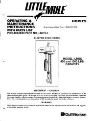
IiSECTION IVIt'IAINTENANCE4-1. INSPECTIOI{S.4-2. A planned inspection routine should be establishedfor this hoist based upon frequency of use,severity of use, and environmental conditions. Someinspections should be made frequently (daily to monthly)and others periodically (monthly to yearly). It isstrongly recommended that an Inspection and MaintenanceCheck List and an Inspector's Report similiarto those shown in figures 4-4 and 4-5 be used andfiled for reference. All inspections should be made by,or under the direction of a designated inspector.Special inspections should be made following anysignificant repairs or any operating occurence leadingone to suspect that the hoist's capabilities may havebeen impaired. Refer to paragraphs 4-13 and 4-25 forassistance in any disassembly and assembly necessaryfor inspections and subsequent replacementor repair. Prior to inspection, clean <strong>part</strong>s as required.See paragraph 4-21.4_3. FREOUENT INSPECTIONS.4-4. Perform the following inspections daily prior toinitial use of the hoist. Also, observe during operationfor any damage which might appear between regularinspections.CAUTION: Any unsafe condition disclosed by the inspectionshall be corrected before operation of thehoist is resumed. Adjustments and repairs shall bedone only by designated personnel.a. Inspect the hooks for deformations, chemicaldamage or cracks. Hooks damaged by chemicals, deformationor cracks, or having throat openings greaterthan the "Maximum Allowable Opening" shown in figure4-1 must be replaced. If the hook is twisted morethan 10 degrees from the plane of the unbent hook, itmust be replaced.Note: Any hook that is twisted or has throat openingsin excess of those listed in figure4-1 indicates abuseTHROAT OPENING(w,/o LATCH)HOISTREJECT HOOK OPENINGMODEL NO.TOP HOOK BOTTOM HOOK<strong>MA</strong>-15 r-7 /32" r-7/32"<strong>MA</strong>-15-2 r-7 /32" L-7 /32"<strong>MA</strong>-15-2W r-7 /32" r-7 /32"<strong>MA</strong>_30 r-13/32" r-r3/32"<strong>MA</strong>-30-2 r-3/ 4" r-3/ 4"<strong>MA</strong>-30-2W r-3/4" r-3/ 4"<strong>MA</strong>-30-3 2-S/32" 2-5/32"<strong>MA</strong>-30-4 2-s/32" 2-5/32"FIGURE 4-1. HOOK THROAT OPENINGor overloading of the hoist. Other load bearing componentsshould be inspected accordingly.b. Check that both hooks swivel freely.c. Check the hoist handle for bends. If the handleis bent, the hoist has probably been highlyoverloaded. A qualified service man should inspebtthe hoist for other damage or return the hoist to thefactory.d. Check load chain for wear, twist and distortion_and ensure that dead end ring or connection issecure. Also check the chain for presence of foreignmaterial and adequate lubrication.4-5. PERTODIC INSPECTIONS.4-6. It is recommended that the following inspectionsbe performed at one to 12 month intervals. The exactperiod of inspection will depend on frequency and typeof usage. Determination of this period will be basedon the user's experience. It is recommended that theuser begin with a monthly inspection and extend theperiods to quarterly, semi-annually or annually basedon his monthly experience.CAUTION: Any unsafe condition disclosed by theinspection shall be corrected before operation of thehoist is resumed. Adjustments and repairs shall bedone only by designated personnel.a. Perform all the frequent inspections listedin paragraph 4-4.b. Check nuts. bolts and other hardware forlooseness, stripped or damaged threads.c. Check load sheave and chain attachmentsfor distortion, cracks and excessive wear.d. Check pawls for excessive wear, bindingand missing or broken pins.e. Check pawl springs for breaks, corrosionand continued ability to hold pawl properly:f. Check load pawl shaft for excessive wear.g. Inspect gear and pinion shaft for adequatelubrication, cracks, distortion, worn or broken teeth.h. Inspect bearings for adequate lubrication,distortion. cracks and excessive wear.i. Check housing, covers, swivel frames, loadblocks and outrigger for cracks and distortion.j. Inspect hub for damage to threads. Checkhub and thrust washer for scoring or other damage tobraking surfaces.k. Check brake discs for excessive wear,glazing or oil contamination. Replace discs worn to athickness of 5/64 inch or less.l. Inspect seals, "o" rings an! gaskets fordeterioration and wear.m. Inspect decal and capacity plate forlegibility.n. Inspect supporting structure for continuedability to support imposed loads.o. Inspect the chain for gouges, nicks, weldsplatter, corrosion and distorted links. Slacken thejtIf,lAmericrane & <strong>Hoist</strong> Corp 1-800-652-1932
chain and inspect for wear at contact points. If wearis observed, or if stretching is suspected, measurethe chain per paragraph 4-10. If any portion of thechain is worn, nicked, twisted or stretched, replacethe whole chain.CAUTION: Do not attempt to reweld sections of thechain and do not try to add on to the chain. Use onlychain supplied by our company, it is specially manufacturedto very close tolerances of dimension,composition and heat treatment. A substitute chainmay damage the load sheave, Never use "missinglinks" because they will jam in the load sheave.p. Check hooks for cracks using dye penetrant,magnetrc <strong>part</strong>icle or other suitable detection method.4-7. INSPECTION OF HOIST NOT IN REGULAR USE.4-8. If the hoist has been idle for one month or more,perform the inspections listed in paragraph 4-4. If thehoist has been idle more than six months, perform theinspections listed in paragraph 4-6.4-9. CHECKING CHAIN FOR WEAR.4-10. Chain inspection and evaluation is a veryimportant phase of hoist maintenance. In general,removal of the load chain from the hoist is not necessary.To check the load chain for excessive wear,proceed as follows:a. Inspect the chain for"elongation", which isa condition caused by overloading or wear. Table IIshows the normal and reject lengths for <strong>MA</strong> hoistchain. A cnain gauge similiar to that shown in figure4-2 or a Vernier caliper may be used. Hang the chainup or stretch it out on a work table in a taut position.Place one edge of the gauge or caliper over the end ofa chain link. The number of links within the gaugelimits will correspond to the "Number of Links" asindicated in Table II. If the last link, which should bewithin the gauge limits, makes contact or extends pastthe inside edge of the gauge, or if the reading of theREJECT LENGTH SEE TABLE IINORI\4AL LENGTH -FIGURE 4-2. CHAIN SALVAGE GAUGEVernier caliper is equal to or greater than the "RejectLength", the entire chain shall be replaced. If thelast link does not contact the edge of the gauge, or theVernier caliper reading is less than the "RejectLength", check the chain along its entire length. Ifall readings are within tolerance, the chain is free ofelongation.b. Inspect each individual chain link for wearto diameter of the link. See figure 4-3. The nominaldiameter of the link is 0.250 inch for the JL-19-Bchain and 0.312 inch for the C-19-10 chain. If thediameter for arty link of JL-19-B chain is less than0.200 inch, replace the entire chain. If the diameter ofany link of C-19-10 chain is less than 0.275 inch,replace the entire chain.WEAR INTHESE AREASFIGURE 4-3. TYPICAL WEAR ON LINKS4-11. LUBRICATION.4-L2. Proper lubrication is necessary for a long andrelatively trouble-free hoist operation. Refer to thefollowing and to Table III, Recommended LubricationSchedule, for lubrication points, type of lubricant andfrequency of lubrication.a. LOAD CHAIN. Clean the load chain'withacid-free solvent and coat with <strong>Coffing</strong> Chain LubricantNo. H-7595, or equivalent. Allow oil to work intoeach link end and be carried into the sheave pockets.Wipe excess oil to prevent dripping.b. During periodic inspection apply a light coatingof <strong>Coffing</strong> No. H-7577 grease to bearing surfaces of loadpawl shaft; to grease seals; to o-rings; to pinion shaft andgear teeth; and to all bearings. Use H-7593 grease on gearteeth.c. BOTTOM HOOK BEARING. Invert bottomhook and allow a few drops of SAE 20-30 oil to rundown the hook shank and into the swivel.d. TOP HOOK. Allow a few drops of SAE20-30 oil to run down between the housing and hookshank.CHAINPART NO.NOM.DIA.NO. OFLINKSTABLE II. LOAD CHAIN LINKNOR<strong>MA</strong>L LGTH.FOR NO. LINKSREJECT LGTH.FOR NO. LINKSGAUGENUMBERJL-19-B* .250 19 14.776 14.957 cA-3441c-1 9-10** .3t2 19 17.832 18.069 cA-344L-2*Used on <strong>MA</strong>-15, <strong>MA</strong>-15-2 and <strong>MA</strong>-15-2W. **Used on <strong>MA</strong>-30, <strong>MA</strong>-30-2, <strong>MA</strong>-30-2W, <strong>MA</strong>-30-3 and <strong>MA</strong>-30-4.Americrane & <strong>Hoist</strong> Corp 1-800-652-1932
E. BOTTOM BLOCK SHAFT AND BUSHING(Multiple Chained Models). Disassemble bottom blockto the degree required to remove shaft. Lubricate shaftand bushing with SAE 20-30 oil.4-I3.DISASSEMBLY.4-14. The following paragraphs suggest the easiestmethod of disassembly and reassembly of the <strong>MA</strong>hoists. Procedures are included for all eight hoists inthe series, with references made to the exploded viewillustrations in Section V for <strong>part</strong>s identification. Useonly those assembly/disassembly procedures identifiedas applicable to your hoist. Some procedures forone hoist may reference steps already delineated foranother hoist; this is done to avoid too much repetitiousprocedure since all eight hoists have muchcommon constructron.4-15. It is expected that whenever any <strong>part</strong> is removedfrom the hoist that the <strong>part</strong> will be cleaned andinspected before reuse. Some instructions for cleaningand inspection are located between the disassemblyand reassembly paragraphs. Always give carefulattention to lubrication of <strong>part</strong>s during reassembly.4-16. <strong>MA</strong>-15 DISASSEMBLY. Disassemblethe <strong>MA</strong>-15hoist as follows while referencins figure 5-1.a. Remove nut (44) and swivel screw (45). Placecontrol lever (7) strarght out, midway between "UP" and"DN" positions. Place lever (34) toward hook housing andhold it there. Pull load chain (46) bv pulling end ring (47)until chain is clear of hoist. Remove end ring only if replacementis required.b. Separate swivel f rames (48) f rom bottomhook assembly (a9). Do not remove latch (50) frombottom hook unless replacement is required.c. Remove pin (37) from top hook (51) shaft.Separate nut (52) from top hook and remove nut, hookwasher (53) and top hook. Do not remove latch (50)from top hook unless replacement is required.d. Remove screw (1) and retainer cap (2).Remove ring (3) from retainer cap. Separate handle (10)from hub (18).e. Punch plug (4) from handle (10). Drivepins (5 and 6) from handle pawl rod (9). Removelever (7), spring (8) and handle pawl rod from handle.f. Lift thread stop (11) from hub (18). I?emovefour screws (12) and lockwashers (13).CAUTION: Take care not to damage sealing surfacesof cover (16) and housing (43) when removing cover.To loosen cover (16) so that its sealing surface willnot be damaged, manually turn the hub (18) clockwise.This will pull the cover loose so it can be removed byhand. Be careful not to damage the gasket (14) or oilseal (15). Remove the cover from housing and, ifreplacement is required, remove oil seal (15) fromcover. Remove gasket (14) from housing.g. Remove hub (18) from load sheave (32).Slide front brake disc (19), ratchet (20), rear brakedisc (22) and thrust bearing (23) from load sheave. Ifreplacernent is required, press bearing (2t1 fromratchet.h. Remove spring (24) and load pawl (25) fromload pawl shaft (38).i. Remove screws (29) and lockwashers (13).Slide shedder (30) from housing (43). Remove ring (27'.and washer (28) from load sheave (32) and slide loadsheave from housing. Remove pin (31) from sheave.j. Drive pin (33) from lever (34) and removelever from shaft (38). Slide shaft from housing (43) andremove ring (35) and washer (36) from shaft. If pin (37)requires replacement, press pin from shaft.k. If oil seal (39), thrust bearing (40), bearing(41) and pins (42) require replacement, remove theseitems from housing (43).4_17. <strong>MA</strong>_15-2 AND <strong>MA</strong>-15_2W DISASSEMBLY.Disassemble the <strong>MA</strong>-15-2 or <strong>MA</strong>-15-2W hoist asfollows while referencing figure 5-2.a. Press pin (44) from top hook and outriggerassembly (52). Pull load chain (51) through lowersheave (61 for <strong>MA</strong>-15-2 or 70 for <strong>MA</strong>-15-2W hoist).Place control lever straight out, midway between"UP" and "DN" positions. Place lever (34) towardhook housing and hold it there. Pull load chain fromhoist. Remove harness ring (50) from chain only ifreplacement is required.b. (For <strong>MA</strong>-15-2 iloist Only) Remove two nuts(55) and screws (56) and separate frames (57). Removetwo pins (58) and separate shaft (59), bearing (60) andsheave (61). Remove roll pin (62) and remove nut (63)and thrust bearing (64) from hook (65). Remove latch(53) from hook only if replacement is required.b. (For <strong>MA</strong>-15-2W <strong>Hoist</strong> Only) Remove twocotter pins (67) and separate idler pin (68), bearing(69) and sheave (70). Shear two rivets (71) and separatebottom frames (72) fron bottom hook(73). Removelatch (53) from bottom hook onlv if reolacement isrequ i red.c. Remove two pins (45 and 46) from couplingshaft (47). Remove top hook and outrigger assembly(52), coupling shaft, hook collar (48) aird washer (49)from housing (43).d. The remainder of model <strong>MA</strong>-15-2 and<strong>MA</strong>-15-2W <strong>part</strong>s are disassembled in the same manneras the IVIA- 15 hoist. Perform steos d thru k ofparagraph 4-16.4-18. <strong>MA</strong>-30 DISASSEMBLY. Disassemble the<strong>MA</strong>-30hoist as follows while referencing figure 5-3.a. Remove nut (51) and swivel screw (52). Placecontrol lever (7) straight out, midway between "UPn and"DN" positions. Place lever (40) toward hook housing andhold it there. Remove load chain (53) bv pulling end ring(54) until chain is clear of hoist. Remove end ring only IFreplacement is required.b. Separate swivel frames (55) from bottomhook assemblv (56). Do not remove latch (57) frombottom hook unless replacement is required.c. Remove pin (59) from top hook (58) shaft.a,Americrane & <strong>Hoist</strong> Corp 1-800-652-1932
INSPECTION AND <strong>MA</strong>INTENANCE CHECK LISTLEVER OPERATED CHAIN HOISTTYPE OF HOISTLOCATION<strong>MA</strong>NUFACTURERCAPACITYORIGINAL USE OATE<strong>MA</strong>NUFACTURER'SERI AL NO.ITEMLoad ChainHooksHook Retai nersPawl, RatchetPawl SpringBrake <strong>Parts</strong>:RatchetB rake Di scsHubThrust YVasherSeals. "O" Ringsand GasketHandle Palts:Pawl RodPawl SpringHandleNuts, Bolts, RivetsSheave, PinionShaft, GearBeari ngsHousing, Covers,Swivel Frames, LoadBlocks & OutriggersSupporting StructureDecal, Capacity PlateFREOUENCY OF INSPECTIONFREOUENT PERtOOtCDAILY MONTHLY 1-12 MO.POSSIBLE DEFICIENCIES OK ACTIONREOUIREDInadequate lubrication, excess ivewear or stretch, cracked, danngedor twisted links, corrosion orforeion substanceExcessive throat opening, bent ortwisted more than 10 degrees,damaged hook latch, wear, chemicaldannge, wsn hook bearing.Cracks (use dye penetrant, magnetic <strong>part</strong>icleor other suitable deteciion method)Worn or dannged nuts, pins, washers,collars used to secure hook in loadblock or housinglYear and bindingBreaks, corrosion, ability to relain pawllYear, binding, worn bearingExcessive wear, glazing, greaseScoring. thread damageScoring, greaseWear, DeteriorationWear, bindingBreaks, corrosion, ability to keep rdin positionCracks, bendsLooseness, stripped or damaged threadsDannge to teeth, distortion, cracks,excessive wear, build up of foreignsubstancesAdequate lubrication, wearCracks, DistortionDamage or wear which restrictsability to support imposed loadsMissinq, damaqed or illeqibleNOTE: Refer to Maintenance and Inspection Sections of the <strong>Hoist</strong> Manual for lurther details.FREOUENCY OF INSPECTION:Frequent - Indicates items requiring inspection daily to monthly. Daily inspections may be performed by the operator if properlydesignated.Periodic- Indicates items requiring inspection monthly to yearly. Inspections to be performed by or under the direction of aproperly designated person. The exact period of inspection will depend on frequency and type of usage. Determinationof this period will be based on the user's experience. lt is recommendsd that the user begin with a rnonthly inspectionand extend the periods to quarterly, semi-annually or annually based on his monthlyexperience.FIGURE 4_4. INSPECTION AND <strong>MA</strong>INTENANCE CHECK LISTAmericrane & <strong>Hoist</strong> Corp 1-800-652-19329
II{SPECIOR'S REPORTITEMRE<strong>MA</strong>RKS ILIST DEF]CIENCIES ANO RECO'IIMENDED ACTIONItfttsPEcTonsSIGNATUREDATEINSPECTEO APMOVED BY DATEFIGURE 4-5. RECOMMENDED INSPECTORS REFMTAmericrane & <strong>Hoist</strong> Corp 1-800-652-1932TABLE III. RECOMMENDED LUBRICATION SCHEDULECOMPONENT ryPE OF LUBRICANT TYPE OF SERVICE ANDFREOUENCY OF LUBRICATIONLoad Chain D-N No. H-7595 penetrating ollwith graphit€ or moly additiveAlternate-SAE 2G30 goar oilLoad Pawl Shaft,Pinion Shaft, Gearand BearinosD-N No. H-7577 greaeoPinion and G€ar Teoth D-N No. H-7593 greaseHEAVY NOR<strong>MA</strong>L INFFEQUENTDaily Weekly MonthlyAt p€riodic inspection (So€ Flgure tl'f)Bottom Hook Bearino SAE 2G'30 oear oil Weekly Monthly YearlyTop Hook Wash€r SAE 20€0 gear oil Monthly Yearly YoarlyBottom Block Shattand BearingSAE 20-30 gear oil Monthly Yearly Yearly'Thi8 lubrication schedul€ is basgd on a hoigt operating in normal onvironmental condltlons. <strong><strong>Hoist</strong>s</strong> operating inadvgrs€ atmospheres conlaining excessive h€at, corrosive fumes or vapors, abrasiv€ dust, etc., should be lubricat€dmor€ irequsntly.troa
TABLE IV. TROUBLESHOOTING CHART,rw-IF DISASSEMBLY OF UNIT IS REOUIRED, REFER TO PARAGRAPH 4-13. TEST HOIST PER PARAGRAPH 2_6AFTE REASSEMBLY OR REPLACEMENT OF ANY OF ITS COMPONENT PARTS.SYMPTOM1. <strong>Hoist</strong> raises but will notlower.POSSIBLE CAUSE(S)"Brake Lock-Up" caused by shockload, leaving load on hoist forextended periods of time or removingload from hoist withoutslacking chain.2. <strong>Hoist</strong> lowers erratically. (a) Brake friction surfaces arecontaminated with oil orgrease.(bl Brake discs are worn or glazed.3. <strong>Hoist</strong> requires excessiveeffort to raise or lower.4. Hoi st wi ll mt raise orlower.5. <strong>Hoist</strong> "Free Chains"under load.6. <strong>Hoist</strong> diff icult to "FreeChain".(a) Overloading(b)Worn or danraged load chain.{c) Load Chain rusty or coatedwith foreign material.(d) Load sheave or guide portionof housing have build-up offoreign material.(e) Worn gearing or bearings.(a) Chein jammed in housing(bl Eroken load sheave(c) Broken or worn tip on handlepawl or stripped spline onbrake hub.(a) Load pawl not engaged (freechain lever sticks)(b) Brake hub not operating freely.(c) Load chain installed fromwrong side of load sheave.See 3 (b) (c) & (d)CORRECTIVE ACTIONUnlock brake following procedureoutlined on Page 3. Check applicationfor conditions suggested in"Possible cause(s!".(a) Replace brake discs and wipemating friction surfaces clean.(b) Replacebrake discs if wornexcessively. remove glaze byplacing a fine grade emorycloth on a flat surface andrubbing discs lightly on thissurface.(a) Reduce load or use correctcapacity unit.(b) Check chain per instructionson Page 5 and replace ifnecessary.(c) Clean chain with suitable acidfreesolvent and relubricate.Replace chain if badly pittedwith rust.{d) Disassemble <strong>part</strong> and clean outforeign material. Inspect andreplace <strong>part</strong>s if wornexcessi vel y.(e) Disassanble <strong>part</strong>s and checlrfor wear. Replace <strong>part</strong>s ifnecessary and relubricate.(al (b) & (c)Di sassemble per instructions.Inspect <strong>part</strong>s for wear orbreakage and replace ifnecessary.(a) Check load pawl shaft forbinding condition. Check forbroken load pawl or load pawlspri ng.(b) Check thread in brake hubor mating <strong>part</strong> for damage,corrosion or foreign material.Check for broken or irnproperlypositioned threadstop. (See Fig. 4-6)(c) Correct chain reeving.(See Fig. 4-8)See 3 (b) (cl & (d)Americrane & <strong>Hoist</strong> Corp 1-800-652-193211
12Separate nut (60) from top hook and remove nut, hookrvasher (61) and top hook. Do not remove latch (57)from top hook unless replacement is required.d. Remor,'e screw (l) and retainer cap (2).Remove ring (3) from retainer cap. Separate handle(10) from hub (18).e. Punch plug (4) from handle (10). Dri'"'epins (5 and 6) from handle pawl rod (9). Remo'"'elever (7), spring (8) and handle pawl rod from handle.f. Lift thread stop (ll) from hub (18). Removefour screws (12) and lockwashers (13).CAUTION: Take care not to damage sealing surfacesof co'"'er (16) and housing (50) when removing cover.To loosen cover (16) so that its sealirrg surface rvillnot be damaged, manually turn the hub (18) clockwise.This will pull the co','er loose so it can be remo','ed bvhand. Be careful not to damage the gasket (14) or oilseal ( 15). Remove the co,"'er frorn housing and, ifreplacement is required, remove oil seal (15) fromcover. Remove gasket (14) from housing. Removedecal (17) frorn cover onlv if replacement is required.g. Remove hub (18) from pinion shaft (36).Slide front brake disc (19), ratchet (20), rear brakedisc (22) and thrust washer (23) from load sheave. Ifreplacement is required, press bearing (21) fromra tc het.h. Remor,'e spring (24\ and load pawl (25) fromload pawl shaft (44)i. Remove screws (27) and lockwashers (28),then remove cover (29). Press pins (32) from housing(50) and remove shedder (33). Remove screws (30) andcapacit]' plate (31) if replacement is required.j. Remove gear (34) from shaft of load sheave(37). Remove pin (35) from pinion shaft (36), thenremove pinion shaft, thrust washer (38) and loadsheave.k. Drive pin (39) from lever (40) and removeiever from shaft (44). Slide shaft from housing (50) andremove ring (41) and washer (42) from shaft. If pin (43)requires replacement, press pin from shaft.l. If oil seal (45), bearings (46,47 and 48) andpins (49) require replacement, remove these items fromhousing (50).4_19. <strong>MA</strong>_30-2 AND <strong>MA</strong>-30_2W DISASSEMBLY.Disassemble the <strong>MA</strong>-30-2 or <strong>MA</strong>-30-2W hoist asfollows while referencing figure 5-4.a. Press pin (51) from outrigger (60). Pull loadchain (62) through lower sheave (70 for <strong>MA</strong>-30-2hoist or 80 for <strong>MA</strong>-30-2W hoist). Place control lever(7) straight out, midway between "UP" and "DN"positions. Push lever (40) toward hook housing andhold it there. Pull load chain from hoist. Remove endring (61) from chain only if replacement is required.b. (For <strong>MA</strong>-30-2 <strong>Hoist</strong> Only) Remove twonuts (64) and screws (65) and separate load blockframes (66). Remove pin (67) and separate shaft (68),bearing (69) and sheave (70). Remove pin (71), thentemove nut (72), hook u'asher (73), and thrust bearing(74) from bottom hook (75). Do not remove latch (59)from bottom hook unless replacement is required.b. (For <strong>MA</strong>-30-2W <strong>Hoist</strong> Onlyl Remove twocotter pins (77) and separate load block shaft (78),bearing (79) and sheave (80). Shear two rivets (81)and separate load block frames (82) from bottom hook(83). Do not remove latch (59) from bottom hook unlessreplacement is required.c. Remove screws (52), lockwashers (53) andkeeper (54). Separate outrigger (60) from housing (50).Press pin (55) from top hook (58). Remove nut (56),washer(57) and top hook from outrigger. Do not removelatch (59) from top hook unless replacement isrequired.d. The remainder of model RA-30-2 andRA-30-2W <strong>part</strong>s are disassembled in the same manneras the model <strong>MA</strong>-30 hoist. Perform steps d thru I ofparagraph 4-18 to complete the disassemblr'.4_20, <strong>MA</strong>_30_3 AND <strong>MA</strong>-30_4 DISASSEMBLY.Disassemble the <strong>MA</strong>-30-3 or <strong>MA</strong>-30-4 hoist asfollows while referencing figure 5-5 or figure 5-6, asa ppl icabl e.a. (For <strong>MA</strong>-30-3 <strong>Hoist</strong> Onlv) Removedead endscrew (80, figure 5-5) and nut (66) to separate loadblock frames (70) from load chain (65). Pull chainthrough sheaves (62 and 74)a. (For <strong>MA</strong>-30-4 <strong>Hoist</strong> Only) Remove pin (64,figure 5-6) from outrigger (63) to free end of loadchain (66). Pull chain through sheaves (62 and 74).b. Place control lever (7) straight out, midwalbetween "UP" and "DN" positions. Push ler,'er (40)toward hook housing and hold it there. Pull loadchain (66) from hoist. Remove end ring (65) from chainonly if replacement is required.c. Remove screws (69) and nuts (68) toseparate load block frames (70). Remove pin(s) (71)and disassemble shaft(s) (72), bearing(s) (73) andsheave(s) (74).d. Remove pin (75) and separate nut (76), hookwasher (77) and thrust bearing (78) from bottomhook (79). Do not remove latch (55) from bottom hookunless replacement is required.e. Remove screws (56), lockwashers (57) andkccper (58). Separate outrigger (63) from housing (50).Disassemble pin (59), shaft (60), bearing (61) andsheave (62) from outrigger.f. Press pin (51) from top hook (54). Removenut (52), washer (53) and top hook from outrigger (63).Do not remove latch (55) from top hook unless replacementis required.g. The remainder of models M4-30-3 and<strong>MA</strong>-30-4 <strong>part</strong>s are disassembled in the same manneras the rnodel <strong>MA</strong>-30 hoist. Perform steps d thru I ofparagraph 4-18 to complete the disassembly.4_21, CLEANING.4-22. All <strong>part</strong>s (except self lubricating bearingslocated in housing and bottom block assembly onAmericrane & <strong>Hoist</strong> Corp 1-800-652-1932
14'Locotecutoul in rodon this side withhondle powl leverin lhe position osshown.HANDLE PAWLRODHANDLE PAIVLSPRING PINHANDLE PAI{LSPR INGHANDLE PAIVLLEVER PINHANDL E PAIVLLEVERFIGURE 4-7. LEVER AND ROD ASSEMELYl. See figure 4-8 for diagram of chain reeving.Turn handle pawl lever to "DN" position. Invert thehoist on a work table and move handle until a flatchain pocket in the load sheave (32) can be seen.Drop loose end of the load chain into the side of loadon same side as load pawl lever (34). The first link ofthe chain shall be upstanding in the load sheavegroove, with the weld on the link facing away from theload sheave. The second link of chain should ride inone of the load sheave pockets. Use handle to turnsheave in the lowering direction. As the end of thechain moves around load sheave, turn hoist upright soload chain will move around load sheave correctly andoui of housing.m. Attach the first link of chain (46)to swivelframes (48) with swivel screw (45) and nut (44). Ifend ring (47) was removed, attach ring to oppositeend of chain.n. Coat the load chain with Coff ing ChainLubricant No. H-7595, or equivalent. Allow oil towork into each link and be carried into the sheavepockets. Wipe oil to prevent dripping.o. Allow a ferv drops of SAE 20-30 oil to rundown the bottom hook shank and into the swivel. Allowa few drops of SAE 20-30 oil to run down betweenhousing and top hook washer.p. Test the hoist per paragraph 2-6 beforeplacing hoist in use.4_28. <strong>MA</strong>-15-2 AND <strong>MA</strong>-l5-2W ASSEMBLY.Assemble the <strong>MA</strong>-15-2 or <strong>MA</strong>-15-2W hoist as followswhile referencing figure 5-2.a. Perform steps a thru i of paragraph 4-27.b. Insert coupling shaft (47) in housing (43).Place washer (49) and hook collar (48) ontg end ofshaft and secure with pin (45). Place top hook andoutrigger assembly (52) over coupling shaft and securewith pin (46). If latch (53) was removed, attach latchto top hook.Americrane & <strong>Hoist</strong> Corp 1-800-652-1932c. (For <strong>MA</strong>-15-2 <strong>Hoist</strong> Only) Place thrustbearing (64) on bottom hook (65) and secure withnut (63). Place hook in one load block frame (57) andscrew nut on hook until approximately L/64 inchvertical play (to allow hook to swivel freely) remains.Align pin hole in hook and slot in nut and insertpin (62). Assemble shaft (59), bearing (60), sheave(61) and pins (58). Assemble load block frames (57)and hook and secure with screws (56) and nuts (55).If latch (53) was removed, attach latch to bottomhook.c. (For <strong>MA</strong>-15-2W <strong>Hoist</strong> Only) Position twoblock frames (72) over hook (73) and secure with tworivets (71). Place idler pin (68), bearing (69) andsheave (70) in frames and secure with two cotterpins (67). If latch (53) was removed, attach latch tobottom hook.d. Perform step I of paragraph 4-27.e. Route the load chain (51) around sheave ofbottom block (with chain welds next to sheave), thenattach the first link of chain to top hook and outriggerassembly (52) with pin (44). Make sure there are notwists in the chain. If harness ring (50) was removed,attach ring to opposite end of chain.f. Perform steps n, o and p of paragraph 4-27.4-29. <strong>MA</strong>-30 ASSEMBLY. Assemble the <strong>MA</strong>-30hoist as follows while referencing figure 5-3.a. If oil seal (45), bearings (46, 47 and 48) orpins (49) were removed, press these items intohousing (50).b. If pin (43) was removed, press pin in shaft(44) until 1/8 inch of the pin protrudes from the top ofshaft. Place washer (42) and ring (41) on shaft andinsert shaft in housing (50). Secure lever (40) to shaftwith pin (39).c. Install thrust washer (38) and pinion shaft(36) in housing (50). Insert pin (35) in pinion shaft.Install load sheave (37) in housing and place gear (34)on load sheave.d. If capacity plate (31) was removed, attachplate to cover (29) with two screws (30). Secureshedder (33) to housing (50) with two pins (32). Attachcover to housing with two screws (27) and lockwashers(28).e. Place load pawl (25) on shaft (44) so that thelong end of shaft pin (43) is located between pins. Thisallows load pawl to be moved out of engagement with theratchet for free chaining. Install spring (24) and test theaction of load pawl by trrming lever (40).f. If bearing (21) was removed, press bearinginto ratchet (20) until bearing is flush with side ofratchet that fits against rear brake'disc (22). Checkthat the ratchet (20), thrust bearing (23), hub (18) andbrake discs (19 and 22) are free of oil or othercontamination. Install these <strong>part</strong>s on pinion shaft (36)while taking care not to get oil, grease or fingerprintson friction surfaces.
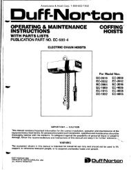
thru sheave (74), thru sheave (62) and then attachloose end to bottom block with dead end screw (80)and nut (66). On the model <strong>MA</strong>-30-4 hoist route chainthru first sheave (74) in load block, then thru sheave(62), back thru second sheave (74) in load block,attach loose end of chain to outrigger (63)pin (64).thenwithg. Perform steps n, o and p of. paragraph 4-27E$<strong>MA</strong>-I5<strong>MA</strong>-I5-2 & <strong>MA</strong>-15_2WAmericrane & <strong>Hoist</strong> Corp 1-800-652-1932mA-30-2 & <strong>MA</strong>-30-2W<strong>MA</strong>_30_3<strong>MA</strong>-30-4FIGURE /I-8. CHAIN REEVING16
PARTS LIST FOR MODEL <strong>MA</strong>.15 HOISTIndexFart Name Qty. Fart NoNo.Reo.I ScrewI H-2989-P2 Retainer CapI <strong>MA</strong>-1003 "O" Ring, Retainer CapI H-56084** Plug, HandleI <strong>MA</strong>-2545** Pin, Handle Fawl SpringI H-52496**7**8**9**l0**l0Allt2l3t4l5**16*17l8t920*2l**2224252728293032333435**36Pin, Handle hwl l.everkver. Han0le kwlSpring, Handle PawlHandle Fawl RodHandleWarning DecalThread StopScrew, Cover[,ockwasherGasket, HousingOil SealCorrer, HousingWarning DecalHubBrake Disc, FrontRatchetBearing, RatchetBrake Disc, RearSpring, Load FawlLoad hwlRing, Load SheaveWasher, ReainingScrew. ShedderShedderload SheavePin. Lnad hwl kverLever, Load Pawl Shaft"O" Ring, Load Pawl ShafrLocking BushingIIIIIII42IIIIIIIIIIIII2IIIH-5250<strong>MA</strong>-3I<strong>MA</strong>-3u<strong>MA</strong>4<strong>MA</strong>-I687K6<strong>MA</strong>L-2sl-lH-1882-PH4r34<strong>MA</strong>-560<strong>MA</strong>-562687Kt7<strong>MA</strong>-35<strong>MA</strong>-580-lA<strong>MA</strong>-530<strong>MA</strong>-580-A<strong>MA</strong>-310<strong>MA</strong>-25H-5506<strong>MA</strong>-250H-1847-P<strong>MA</strong>-37<strong>MA</strong>L-16-6H-5240<strong>MA</strong>-32-5H-5607<strong>MA</strong>-24t Not sold sparately 6 a rcpair pan. If rcplaccm€nt is required, prcurc the appropriare followingas€mblv-** Sold individually as a repair pan snd as a pan ofrhe appropriate following as€mbly.IndexNo.Part Name37** Pin38*39**Shaft, Load PawlOil Seal, Housing40** Bearing, load Sheave4l** Bearing, Load Sheave42 Pin, Housing43* Housing4**45**46474g**49**50**5l525354sst56ts8t5et60t6ltNutSwivel ScrewLoad ChainEnd RingSwivel FrameHook Assembly, Bonom(Includes Index No. 50)Iatch KitHook Assembly, Top flncludesIndex No. 50)Nut, Top HookWasher, Top HookCapacity DecalHousing Cover and Oil SealAssembly (Includes IndexNos. 15 and 16)Ratchet Assembly (IncludesIndex Nos. 20 and2l)Housing, Bearings and Oil SealAssembly (Includes IndexNos. 39, N,4l and43)Handle Assembly (IncludesIndex Nos. 4 thru l0)Load Block Assembly (IncludesIndex Nos. 4,45 and48thru 50)L,oad hwl Shaft Assembly(Includes Index Nos. 35, 37and 38)Qty.Reo-2IIII2IIIII2I2IPart No.H-5251<strong>MA</strong>-561RA-534<strong>MA</strong>-531H-5384H-3472-PJF-700JL-I9-B<strong>MA</strong>-75<strong>MA</strong>-20-l3K8SH-7540<strong>MA</strong>-3-l0SH-3986-PJF-260675K7r<strong>MA</strong>-950<strong>MA</strong>-901<strong>MA</strong>-951-6<strong>MA</strong>-908<strong>MA</strong>-913-20<strong>MA</strong>-900f Assembly not indexcd on illusrralion. 118Americrane & <strong>Hoist</strong> Corp 1-800-652-1932
Americrane & <strong>Hoist</strong> Corp 1-800-652-1932FIGURE 5_1. EXPLODED ILLUSIRATION OF MODEL <strong>MA</strong>_15 HOIST19
PARTS LIST FOR MODEL <strong>MA</strong>.15-2 AND <strong>MA</strong>.15.2W HOISTSlndexPart Name Qty. Part No.IndexNo.Reo-No.Fart Namet As$nbly not indcxcd on illusrarion. I ScrewI H-2989-P 5l Inad Chain2 Retainer CapI <strong>MA</strong>-10052 Top Hook and Outrigger3 "O" Ring, Reainer CapI H-5608Assembly (Includes Index4** Plug, HandleI <strong>MA</strong>-254No. 53)5** Pin, Handle Pawl SpringI H-524953** Latch Kit6** Pin, Handle Fawl leverI H-525054t Ioad Block Assembly (Consists7** kver, Handle FawlI <strong>MA</strong>-3Ioflndex Nos. 55 thru 65)8** Spring, Handle PawlI <strong>MA</strong>-3ll55 Nut9** Handle Fawl RodI <strong>MA</strong>455A [.ockwasherl0** HandleI <strong>MA</strong>-I56 Screwl0A Warning DecalI 687K6)t Load Block Framell Thread StopI <strong>MA</strong>L-251- l5g** Pint2 Screw, Cover4 H-1882-P59** Shaftl3 lockwasher) H4t3460** Bearingt4 Gasket, HousingI <strong>MA</strong>-5606l* Sheavel5** Oil SealI <strong>MA</strong>-562 62 Pinl6* Cover HousingI63 Nutt7 Waming DecalI 687K17& Thrust Bearingl8 HubI <strong>MA</strong>-3565 Bottom Hook 0ncludes Indext9 Brake Disc. FrontI <strong>MA</strong>-580-1ANo. 53)20* RarchetI66t L,oad Block Assembly (Consists2l**22Bearing, RatchetBrake Disc, RearII<strong>MA</strong>-530<strong>MA</strong>-580-A 67of Index Nos. 67 thru 73)Cotter Pin24 Spring, Load kwlI <strong>MA</strong>-31068 Idler Pin25 Load hwlI <strong>MA</strong>-2569** Bearing27 Ring, Load SheaveI H-550670* Sheave2829Washer, ReainingScrew, ShedderI2<strong>MA</strong>-250H-1847-P7l1)RivetBlock Frame30 ShedderI <strong>MA</strong>-3773 Bonom Hook32 load SheaveI <strong>MA</strong>L-16-674 Capacity Decal33 Pin, load Pawl l,everI H-52407st Housing Correr and Oil Sealll34 kver, Load PawlI <strong>MA</strong>-32-5Assembly (Includes Index35** "O" Ring, Load Pawl Shaft I H-5607Nos. 15 and 16)I36 Locking BushingI <strong>MA</strong>-24 76t Ratchet Assembly (IncludesI,l 37** Pin2 H-5251Index Nos. 20 and2l)38* Shaft, load PawlI78t Housing, Bearings and Oil SealI al39** Oil Seal, HousingI <strong>MA</strong>-561Assembly (Includes Indexlr40** Bearing, [oad SheaveI RA-534Nos. 39, 40,41 and43)ll 4l** Bearing, [oad SheaveI <strong>MA</strong>-531 7et Handle Assembly (IncludesI42 Pin, Housing2 H-5384Index Nos. 4 thru l0)43* HousingI80t load hwl Shaft Assembly(Includes4 PinI H-5123Index Nos. 35,45 PinI H-5r22-P37 and 38)6 PinI H-5129-P8lt Load Block Sheave and ShaftAssembly (Includes47 Coupling ShaftI <strong>MA</strong>-106Index48 Hook CollarI JF-108Nos. 58, 59, 60 and 6l)82t Inad Block Sheave and Bearing49 WasherJF-zffiAssembly (Includes Index50 End Rine<strong>MA</strong>-75Nos. 69 and 70)r Not sold spantcly s a rcpair pan. If replacement is rcquired, praure thc appropriate followingasFmbly.** Sold individually s r rcpair pan and as a pan of thc appropriatc following assmbly.Americrane & <strong>Hoist</strong> Corp 1-800-652-1932Qty.Reo.II2I22a22IIIIIIII2III22IIIIIPart NoJL-19-BI<strong>MA</strong>-9ls-17lH-7540IF-9r4-7H-3473-PH4063-PH-2403-PJF-30H-5234JF-122-lHJ.I6-8H-525rH-3986-PJF-5103K6SBBB-57-2H-5029HJ-28-AHJ-I6-8H4562HJ-303K8S675K70<strong>MA</strong>-950<strong>MA</strong>-901<strong>MA</strong>-951-6<strong>MA</strong>-908<strong>MA</strong>-900JF-917BB-57-1v)u20
.i uAmericrane & <strong>Hoist</strong> Corp 1-800-652-1932l#;53---(,514t,It *5555r5756*'FIGURE 5-3. EXPLODED ILLUSTRATION OF MODEL <strong>MA</strong>-30 HOIST
FPARTS LIST FOR MODEL <strong>MA</strong>.3O-2 AND <strong>MA</strong>.3O.2W HOISTSIndexPart Name Qty. Fart No.IndexNo.Req.No.I Screw, Retainer CapI H-2989-P 60**2 Retainer CapI <strong>MA</strong>-100 6l3 "O" Ring, Reainer CapI H-5608 624** Plug, HandleI <strong>MA</strong>-254 63t5** Pin, Handle hwl Spring I H-52496**7**8**9**l0**l0Allt2t4l5**l6*17l8l920*2l**22232425272829303l3233343536373839404l*x4243**44,F45**46**47**4g**4950*5lst535455x*56**57**58*x59**Pin. Handle Pawl kverlever, Handle PawlSpring, Handle PawlHandle Pawl RodHandleWarning DecalThread StopScrew, CoverGasket, HousingOil Seal, CorrerCover, HousingWaming DecalHubBrake Disc. FrontRatchetBearing, RatchetBrake Disc. RearThrust WasherSpring, Load Fawlload FawlScrew, Gear CoverlockwasherCover. GearScrew, Capacity PlateCapacity PlatePin, Chain ShedderShedderGearPinPinion ShaftLoad SheaveWasher, ThrustPin, L,oad Pawl kverLever, Load Pawl"O" Ring , Load Pawl ShaftLocking BushingPin, load hwl ShaftShaft, Load FawlOil Seal. Pinion ShaftBearing, Pinion ShaftBearing, load SheaveBearing, Load SheavePin, HousingHousingPin, Dead EndScrew, OutriggerLockwasherKeeperPin, Top HookNut, Top HookWasherTop Hook Assembly (IncludesIndex No. 59)Larch KitIIIIIII4IIIIIIIIIIII22I2I2IIIIIIIIIIIII2II2II22IIIII2H-5250<strong>MA</strong>-3I<strong>MA</strong>-3ll<strong>MA</strong>4<strong>MA</strong>-I687K6<strong>MA</strong>L-251-lH-1882-P<strong>MA</strong>-560<strong>MA</strong>-562687K17<strong>MA</strong>-35<strong>MA</strong>-580-lA<strong>MA</strong>-530<strong>MA</strong>-580-A<strong>MA</strong>-33<strong>MA</strong>-310<strong>MA</strong>-25H-1886-PH4138<strong>MA</strong>-11-lH-28@-PcB-675-3H-5126<strong>MA</strong>-37-l<strong>MA</strong>480H-5261<strong>MA</strong>L483<strong>MA</strong>-16-5<strong>MA</strong>-253H-5240<strong>MA</strong>-32-5H-s607<strong>MA</strong>-24H-5251<strong>MA</strong>-563<strong>MA</strong>-533<strong>MA</strong>-531-l<strong>MA</strong>-532H-5384H-5131H-2425-PH4136<strong>MA</strong>-43-lH5234H-3922-PcB-2533JI45H-754x Not sold separately as a rcpair pan. If replscement is required. pr@ure the appropriate followingas9mblv.** Sold individually as a repair pan and as a pad of rhe appropriare following assembly.tAssemblynot indexed on illustration&65667**68**69**70*7l **72**73**74**75**761777879**80*8t828384t8st87t88t8ete0t9ltezre3te4te5te6rOutriggerEnd RingL,oad ChainFart NameBottom Block Assembly(Consists of Index Nos.64 thru 75)NutScrew[,oad Block FramePinLoad Block ShaftBearingSheavePinNutHook WasherThrust BearingBottom Hook (Includes IndexNo. 59)Bottom Block Assembly(Consists of IndexNos. 77 thru 83)Cotter PinLoad Block ShaftBearingSheaveRivetload Block FrameBottom Hook (Includes IndexNo. 59 and Nut)Housing Cover and Oil SealAssembly (Includes IndexNos. 15 and 16)Ratchet Assembly (IncludesIndex Nos. 20 and2l)Load Fawl Shaft Assembly(Includes Index Nos. 41,43 and44)Handle Assembly (IncludesIndex Nos. 4 thru l0)Housing, Bearings and Oil SealAssembly (Includes IndexNos.45, 46,47,48 and 50)Load Block Shaft Assemblv(Includes Index Nos.67 and 68)Bottom Hook Assemblyflncludes Index Nos.7l thru 75)Outrigger Assembly (IncludesIndex Nos. 55 thru 60)Load Block Sheave and BearingAssembly (Includes IndexNos. 79 and 80)L-oad Block Sheave and BearingAssembly (Includes IndexNos. 69 and 70)load Block Assemblv(Model <strong>MA</strong>-30-2) -Load Block Assembly(Model <strong>MA</strong>-30-AIV)Americrane & <strong>Hoist</strong> Corp 1-800-652-193224Qty.Reo.IIII222IIIIIIIIII2III22IIIIIPart No.<strong>MA</strong>-42<strong>MA</strong>-75c-19-10<strong>MA</strong>-9144H-3964-PH-2423-P<strong>MA</strong>.29H-5234<strong>MA</strong>-l0lA-28-BH-5243H-3922-PcB-253cB-510SHL-6SSP-30-SHH-5022F-28-A-lA-28-BH4551HJ-130sHL-llw<strong>MA</strong>-950<strong>MA</strong>-901<strong>MA</strong>-900-2<strong>MA</strong>-908<strong>MA</strong>-951-5<strong>MA</strong>-903<strong>MA</strong>-912-2<strong>MA</strong>-915-5SSP-28ssP-28<strong>MA</strong>-9144ssP-30-sHv{V,u