Small craft â Hull construction - Scantlings â Part 9: Sailing boats ...
Small craft â Hull construction - Scantlings â Part 9: Sailing boats ...
Small craft â Hull construction - Scantlings â Part 9: Sailing boats ...
- No tags were found...

You also want an ePaper? Increase the reach of your titles
YUMPU automatically turns print PDFs into web optimized ePapers that Google loves.
ISO/WD 12215-9Copyright noticeThis ISO document is a working draft or committee draft and is copyright-protected by ISO. While thereproduction of working drafts or committee drafts in any form for use by participants in the ISO standardsdevelopment process is permitted without prior permission from ISO, neither this document nor any extractfrom it may be reproduced, stored or transmitted in any form for any other purpose without prior writtenpermission from ISO.Requests for permission to reproduce this document for the purpose of selling it should be addressed asshown below or to ISO's member body in the country of the requester:[Indicate the full address, telephone number, fax number, telex number, and electronic mail address, asappropriate, of the Copyright Manger of the ISO member body responsible for the secretariat of the TC orSC within the framework of which the working document has been prepared.]Reproduction for sales purposes may be subject to royalty payments or a licensing agreement.Violators may be prosecuted.ii© ISO 2004 — All rights reserved
ISO/WD 12215-99.2.2 Design heeling moment for sailing multihulls ................................................................................159.3 Calculation for single mast ..............................................................................................................159.3.1 Mast compression due to heeling moment.....................................................................................159.3.2 Design and ultimate loads on rid and rig attachment ....................................................................169.3.3 Load on mast step ............................................................................................................................189.4 Distribution of heeling moment between several masts................................................................189.4.1 For a mast with a maximum fraction f between 0,67 and 1.00:......................................................189.4.2 For a mast with a maximum fraction f between 0.30 and 0.67:......................................................1810 <strong>Scantlings</strong> of chainplates.................................................................................................................19Annex A (normative) Example of calculation of a chainplate and its connection.....................................21A.1 Formulas............................................................................................................................................21A.2 Pre-calculated values for typical chainplates .................................................................................22A.2.1 AISI 304 or 316 Stainless steel chainplates ....................................................................................22A.3 Pre-calculated values for typical 5083 Aluminium .........................................................................22A.4 Example of calculation of the junction between the chainplate and the structure......................23A.4.1 Example of bolted junction. .............................................................................................................23A.4.2 Example of welded junction .............................................................................................................23A.4.3 Example of connection of a gusset with the hull............................................................................23iv© ISO 2004 — All rights reserved
ISO/WD 12215-9ForewordISO (the International Organization for Standardization) is a worldwide federation of national standards bodiesISO (the International Organization for Standardization) is a worldwide federation of national standards bodiesInternational Standard ISO 12215 was prepared by Technical Committee ISO/TC 188, <strong>Small</strong> <strong>craft</strong>.Beside this ninth part, ISO 12215 consists of⎯ <strong>Part</strong> 1: Materials - Thermosetting resins, glass fibre reinforcement, reference laminate⎯ <strong>Part</strong> 2: Materials - Core materials for sandwich <strong>construction</strong>, embedded materials⎯ <strong>Part</strong> 3: Materials - Steel, aluminium, wood, other materials⎯ <strong>Part</strong> 4: Workshop and manufacturing⎯ <strong>Part</strong> 5: Design pressures for monohulls, designs stresses, scantlings detrmination⎯ <strong>Part</strong> 6: Structural arrangements and details⎯ <strong>Part</strong> 7: Multihulls⎯ <strong>Part</strong> 8: RuddersThe development of ISO 12215 parts 1 to 9 owes a considerable debt to the energy and work of Mr FritzHARTZ who was involved at the start of the project and was the convener of TC 188 WG 18 until his death onthe 16th of November 2002. All the members of WG 18 and TC 188 wish to express their gratitude for hismajor contribution to the production of this International Standard© ISO 2004 — All rights reserved v
ISO/WD 12215-9IntroductionThe dimensioning according to this International Standard is regarded as reflecting current practice, providedthe <strong>craft</strong> is correctly handled in the sense of good seamanship and operated at a speed appropriate to theprevailing sea state.vi© ISO 2004 — All rights reserved
ISO/WD 12215-93.1design categoriessea and wind conditions for which a boat is assessed by this International Standard to be suitable, providedthe <strong>craft</strong> is correctly handled in the sense of good seamanship and operated at a speed appropriate to theprevailing sea state.3.1.1design category A ("ocean")category of <strong>boats</strong> considered suitable to operate in seas with significant wave heights above 4 m and windspeeds in excess of Beaufort Force 8, but excluding abnormal conditions, e.g. hurricanes.3.1.2design category B ("offshore")category of <strong>boats</strong> considered suitable to operate in seas with significant wave heights up to 4 m and winds ofBeaufort Force 8 or less3.1.3design category C ("inshore")category of <strong>boats</strong> considered suitable to operate in seas with significant wave heights up to 2 m and a typicalsteady wind force of Beaufort Force 6 or less3.1.4design category D ("sheltered waters")category of <strong>boats</strong> considered suitable to operate in waters with significant wave heights up to and including0,30 m with occasional waves of 0,5 m height, for example from passing vessels, and a typical steady windforce of Beaufort 4 or less3.2loaded displacement mass m LDCmass of the <strong>craft</strong>, including all appendages, when in the fully loaded ready for use condition as defined in ISO8666.”3.3sailing <strong>craft</strong>boat for which the primary means of propulsion is by wind power, having a total profile area, As as defined inISO 8666, expressed in m², of all sails that may be set at one time when sailing closed hauled ofAs > 0,07( m LDC ) 2/33.4design category factorf wfactor lowering requirements according to design category, its values are according to Table 1Table 1 — Values of design category factorDesign Category A B C DValue of f w 1 0,9 0,75 0,54 SymbolsUnless specifically otherwise defined, the symbols shown in Table 2 are used in this part of ISO 1215.2 © ISO 2004 — All rights reserved
ISO/WD 12215-9Table 2 — Symbols, coefficients, parametersSymbol Unit Designation/Meaning of symbol Reference/ArticleconcernedPrincipal data5 Design criteria5.1 Design stresses for metal5.1.1 Basic design stressesFor the design tensile, compressive, and flexural loads shall be the smallest ofσ d or 9 σ= 0,5 σ u 0, y where relevant (N/mm²) (1)andτ uτ d =2(N/mm²) (2)where⎯⎯σ d is the design tensile, compressive, and flexural stress (N/mm²)σ u is the ultimate tensile, compressive, and flexural stress (N/mm²)⎯σ y is the yield tensile , compressive, and flexural stress(N/mm²)⎯⎯τdis the design shear stressτuis the design shear stress(N/mm²)(N/mm²)For metal, the design shear stress shall be taken as τ d = 0,577σ dThe design bearing stress shall be taken asσ = 1, 8 σbdNOTE To be consistent with parts 5 and 8 the design stresses of are high. To take this fact into account, the actualloads are raised by an adequate dynamic factor.d© ISO 2004 — All rights reserved 3
ISO/WD 12215-95.1.2 Design stresses for typical bolts or metalsBolts may be made from the unsophisticated black steel to high quality Stainless steel, or non ferrous metalssuch as Monel 400, etc. Only Stainless steel or Carbon steel are considered in the present article, becausethey are the most popular material, but bolts and screws may be made of any material.5.1.2.1 Stainless steel ISO boltsStainless steel is classed by ISO 3506 into four main categories , see Table 3Table 3 — Mechanical properties of ISO SS screws according to ISO 3506-1979ISO material AISI TextureA1 303 AusteniticA2 304 AusteniticA4 316 AusteniticC1 to C4 400 serial MartensiticIf the steel has a low carbon content, the letter L is added after the ISO materialTable 4 — Mechanical properties of ISO SS screws according to ISO 3506-1979Property Class50 70 80σu N/mm² 500 700 800σd N/mm² 250 350 400Class 50 is usually made by machining a thread from a solid rod. This is how are made threaded rods. Thesescrews are used for lowest quality screws.Class 70 and 80 are made by a combination of stamping and cold stretching, this is the most used threads.Quality SS bolts are usually stamped on their head with, on top the identification of the manufacturer wwith 3letters, and below the ISO material and class quality.For example A4 L – 80 means Iso Material A4 with low carbon and Class 80.5.1.2.2 Steel ISO boltsSteel (plain or galvanized) are classed by ISO 898-1 into several classes. The fist digit multiplies by 100 givesthe ultimate strength σ u (N/mm².) The yield strength σ y is obtained by multiplying the fist digit by 10 timesthe second digit.Table 5 — Mechanical properties of ISO Steel screwsISO Class According to ISO 898-1-19884.8 5.6 5.8 6.8 8.8 10.9 12.9σu N/mm² 400 500 500 600 800 1 000 1 200σy N/mm² 320 300 400 480 640 900 1 080σd N/mm² 200 250 250 300 400 500 6005.1.3 Combined design stressesFor metallic elements, equation (3) shall be fulfilled in any point of the stock:4 © ISO 2004 — All rights reserved
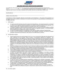
ISO/WD 12215-96 Load on appendages6.1 Gravity and dynamic loads on ballast keels.6.1.1 Load due to heel (see figure 1)M= f Q a is the ballast keel design bending moment at keel junction, (Nm) (5)qd 30wany element of the ballast keel, connection, and boat structure shall not to exceed its design stress under thisload.NOTEThis bending moments includes a factor which reflects dynamic effectswhere⎯ Q is the mass of ballast keel,⎯ a is the vertical distance from CG of keel to keel junction(kg)(m)a: ballast bolted on a skeg b: ballast directly bolted on the hull c: bolted keel not fully ballastedFigure 1 — Different types of bolted ballast keel6.1.2 Maximum longitudinal allowable offset (see figure 2)If the arrangement of the ballast CG is longitudinally distant of more than 0,2 L bolts from a vertical from theCentre of surface of the bolts, it is outside the scope of the present part of ISO 12215.NOTE In this case, the corresponding longitudinal and vertical bending and torsional moments induced by the ballastweight shall also be considered.6 © ISO 2004 — All rights reserved
ISO/WD 12215-9L boltsL boltsCS BoltsCS BoltsCG Q6 % L bolts> 20% L boltsCG Q6.1.3 Vertical load case (see figure 3)Figure 2 — Keel rake smaller or greater than 0,2 LboltsThis case allows for the possibility that the keel could de subjected to a vertical force. Equation (6) presumesa low to moderate impact speed and is intended to cover cases of dry-docking or grounding.considers a slow speed grounding or dry docking with moderate dynamic effect.The boat structure and keel connection and stiffeners shall be able to withstand without exceeding designstresses a vertical force F qvd exerted at the ballast keel CGFqvd= 15f( m − Q)(N) (6)wLDCwhere⎯ m LDC is the fully loaded mass of the <strong>craft</strong> as defined in 3.2(kg)⎯ other dimensions previously defined.6.1.4 Longitudinal load caseThis case allows for acknowledges the possibility that the keel could de subjected to a horizontal force.Equation (7) presumes a low to moderate impact speed and is intended to cover impact of submerged objects.The boat structure and keel connection shall be able to withstand without exceeding design stresses alongitudinal force F qld exerted at the ballast keel CGFLH= 2,4fw( mLDC− Q(N) (7)Tqld )where⎯ T is the maximum draft of the <strong>craft</strong>(m)⎯ other dimensions previously defined.© ISO 2004 — All rights reserved 7
ISO/WD 12215-96.2 Design loads on non ballasted centreboards or daggerboards.6.2.1 Design loads for any type of boardsFor non ballasted boards, the loads and design stresses shall be assessed as for rudders in ISO 12215-8, butusing upwind speed V u instead of maximum speed.hr hVu = 1,5 ⋅1,45V ² A = 2,175 V ² A r(knt) (8)22Where⎯ V is the maximum speed of the <strong>craft</strong>⎯ A is the outside area of the board⎯ h r is the vertical span of the board when the boat is upright(knt)(m²)(m)6.2.2 Design loads for boards fitted on capsize recoverable <strong>boats</strong>For capsize recoverable <strong>boats</strong> according to 12217, the board shall be able to support without exceeding thedesign stress σ d when the force Ftbat the tip of the boardF tb = 10 n 75 = 750 n(N) (9)Where n is the minimal number of persons for recovering from capsize according to ISI 122177 Design strength of ballast keels7.1 Ballast keel material design strengthSee the relevant values in Table 6, or use specific data.7.2 Resistance of ballast keels7.2.1 General caseThe design stress within the ballast keel material(s) shall not be exceeded in any point the design stress.MqdAt the keel junction σ =SMq≤ σ dq(N/mm²) (10)Where⎯⎯M= f Q a is the ballast keel design bending moment at keel junction, (Nm) defined in eq (5)qd 30wSM q is the Section modulus of the ballast keel (cm3) (If the level of keel junction is not the critical one, the same method shall be applied at this level, interpolationgthe heel Moment.8 © ISO 2004 — All rights reserved
ISO/WD 12215-97.2.2 Lead ballastLead or lead alloys have such low mechanical properties that thin and deep fins lead alloy ballasts usuallyneed a steel framing and top flange to allow both sufficient bending strength and connection.As screws of bolts have difficulties to fix in lead, the mechanical connection of lead ballast keel is usuallymade with threaded rods cast in the lead. Their lower part is either bent or connected to plats to ensure acorrect anchoring of these threaded rods in the lead.7.2.3 Case of solid NACA foilFor solid NACA foilsS = C1L f b f(m²) (11)26 LfSM = C210 bf(cm 3 ) (12)6where⎯⎯b f is the maximal beam of the foil (m)L f is the horizontal chord length of the foil (m)⎯ C1 and C2 are given in TableTable 7 — Values of coefficient C 1 and C 2Naca Profile C1 C2001265a12 0,674 0,4607.2.4 Hollow NACA foilTo be implemented, if needed.8 Analysis of bolted ballast keels8.1 Bolt material choice8.1.1 Bolt material for chemical corrosion.All copper bases alloys of Table 6 may be used. Monel is one of the best but expensive.Brass shall not be used in any case as it loses its zinc in sea water environment. Alloy named "Admiraltybrass" is in fact a Bronze that may be used.A2 bolts not recommended if any risk of being under waterA4 bolts highly recommended, but might be subject to corrosion in non oxidizing atmosphere. Care shall betaken when used in wooden <strong>boats</strong>, where under de-oxidized water.© ISO 2004 — All rights reserved 9
ISO/WD 12215-9C1 to C4 (Martensitic stainless steels) may have very high mechanical properties, after heat treatment, but areprone to crevice corrosion under tension, they should therefore only be used with the utmost care and wherethere is very limited risk of corrosion.8.1.2 Prevention of electrolytic corrosionOn aluminium <strong>boats</strong>, non Aluminium bolts shall be electrically insulated from the rest of the structure, forexample by inserting insulation bushings and washers.8.2 Bolt diameter determination8.2.1 Case where the longitudinal bending moment is negligibleIn the case where the longitudinal bending moment is neglected (Keel CG less than 20% of L bolts from boltscentre of surface, see 6.1.2), the bending moment at the keel junction is M qd defined by equation (5).For each bolt, the following inequation (8) shall be fulfilled :1270 biMqdσi= ≤ σd∑ b ² d ²ii(N/mm²) (13)where⎯⎯⎯Mqis the heeling moment defined in 6.1.1, equation (5) (Nm)dd i is the diameter of the neck (at the bottom of the thread )of the bolt considered ( i= 1,2, etc) (mm)b i is the distance between the hinge bearing line and each bolt axis on the opposite side from the ballastcentreline.(mm)⎯∑2 2bidiis the sum of the product of biandd i squared for each bolt row. (mm 4 )The "hinge bearing line" is a fictitious line around which the ballast is considered to bear on the bottom of thehull or skeg. When the boat is upright, the bearing pressure is uniform and equal to the sum of the tensile pretensionloads of the bolts divided by the bearing area. When the boat heels, the windward bearing pressure isrelieved and the leeward pressure is increased to achieve a triangular pressure repartition summarised inFigure 3 a. Pressure is considered nil at hinge bearing line, and the tensile load on each bolts is proportionalto its distance di from hinge line.For foil shaped ballast, Naca profile or equivalent, the hinge line is locatedb0,425q max leeward of keel axisFor ballast with a top flange, the hinge line is located0 ,5 bfleeward of keel axisWherebqmax is the maximum width of the keel at its bolting level, and bfthe flange widthThe 0,425bqmax value is considered as the mean of the effective bearing curve of the foil.(85% of mid width)8.2.2 Bearing pressure topicsThe maximum bearing pressure at the hinge line level is10 © ISO 2004 — All rights reserved
ISO/WD 12215-9pp126 fQ awmax = ≤ 0,5σbu for keel without a top flange (N/mm²) (14)2Lqbqmax91 fQ awmax = ≤ 0,5σbu for keel with a top flange (N/mm²) (15)2LfbfNOTE Equation (5) comes from the equilibrium between pressure and bendingLq0,85 bqmax pmaxmoment:0,66 0,85 bqmax = 30 fw Q a2As the surfaces of respectively the top of the ballast keel and bottom of hull or skeg cannot perfectly match inpractice, a intermediate layer jointing compound, usually made or reinforced resin, is usually placed inbetween. The design compressive strength of this material shall be greater that the maximal bearing pressuredefined above.For wooden <strong>boats</strong>, the wood crushing strength is often lower than the maximal bearing pressure. The woodshall therefore be reinforced by a saturation of pure and/or reinforced epoxy resin.For lead keels, the ultimate compression of lead, even allowed with antimony, is very low, and care shall betaken to avoid that the bearing design pressure to be greater than the lead design compressive strength. Leadis often reinforce by a steel backbone and upper flange.According to Annex E of ISO 12215-5 the crushing strength of wood is respectively 0,073 ρ and 0,070 ρ forsoftwoods and hardwoods, where ρ is the wood density (kg/m 3 )8.2.3 Bolt diameter rough evaluationBefore applying equation (13) a rough evaluation of the bolt diameter for a first iteration of formula (13), onecan use formula (16) which is only fully valid if all the biand d i are respectively the same.d approx =i1270. Mσ .d∑bqdiapproximate neck diameter of the bolts (mm) (16)© ISO 2004 — All rights reserved 11
ISO/WD 12215-9F1 F2 F3 F4 F5b i1d1d2d3di4di3di0,425 bqmax b1 b2 b3 bi1bqmaxbF1F2 F3 F4 F5d1d2d3di4di3diaCL0,425 bqmax b1b2b3bibqmax1cFigure a : Sketch of transverse load Figure b: Keel directly bolted Figure c: Keel with a top flangeKey:1 Bearing line // to centreline at 0,425 b q max of b flange maxFigure 3 — Sketch of keel bolts8.2.4 Validity of the calculationsThe above calculation is only valid if all the bolts are stressed. This condition is considered met if :⎯ the bolts are less than 20di from the closest part of the floor.⎯ the bolts are fitted with counter plates and washers. This counter plate shall be at least 0,25 di thick, atleast 3di wide, and 3di beamier each side than the bolts (see Figure 3).The counter plates can be madeeven stiffer if fitted with one or two flanges ( L or U shaped)⎯ give requirements for ratio of cast iron flange protruding length to thickness according to strength : to beimplemented at DIS stageWith these above conditions, the bolts are considered as fully stressed and the effort is fed to the floor byshear stress, either via laminated angles or welds.If the bolts are farther from floors, the shell is normally not stiff enough to stress all the bolts, then keelsonsable to transmit the bolt loads are needed, or only the bolts really working will be considered.The above keelsons shall be able to transmit M and F according to the force of the bolts and their distancefrom the floor.12 © ISO 2004 — All rights reserved
ISO/WD 12215-98.2.5 Bolt final evaluationEquation (8) is only related to the neck diameter of the bolt, i.e the diameter at the bottom of the thread.Table 3 gives the correspondence between this neck diameter and the nominal diameter according to threadtype.Where a bolt diameter is on table 3, and pitch is not known, normal pitch is to be assumed.Where a bolt diameter is not on table 3,⎯ - if the pitch is known⎯ - if the pitch is not knownd neck = d-1,227 pd neck =0,82 dTable 8 — Values ISO M ScrewsNormal PitchFine Pitchd p d neck S neck p d neck S necknominal (pitch) ISO d 3 (pitch) ISO d 3mm mm mm mm² mm mm mm²12 1,75 9,85 76,2 1,5 10,16 81,114 2,00 11,55 104,7 1,5 12,16 116,116 2,00 13,55 144,1 1,5 14,16 157,518 2,50 14,93 175,1 1,5 16,16 205,120 2,50 16,93 225,2 1,5 18,16 259,022 2,50 18,93 281,5 1,5 20,16 319,224 3,00 20,32 324,3 1,5 22,16 385,727 3,00 23,32 427,1 1,5 25,16 497,230 3,50 25,71 519,0 2,0 27,55 596,033 3,50 28,71 647,2 3,0 29,32 675,236 4,00 31,09 759,3 3,0 32,32 820,439 4,00 34,09 912,9 3,0 35,32 979,842 4,50 36,48 1045,2 4,0 37,09 1080,645 4,50 39,48 1224,1 4,0 40,09 1262,548 5,00 41,87 1376,6 4,0 43,09 1458,552 5,00 45,87 1652,2 4,0 47,09 1741,856 5,50 49,25 1905,2 4,0 51,09 2050,360 5,50 53,25 2227,3 4,0 55,09 2383,964 6,00 56,64 2519,6 4,0 59,09 2742,68.2.6 Bolt screwing and pre-stressingScrews and nuts shall be tightened to ensure pre-stressing.Tightening torque is a function of many parameters such as screw and nut material, screw treatment, frictionbraking or washers and lubrication. The values of Table 8 are generally recommended values for normalscrew pitch. They correspond to a friction coefficient of 0,125© ISO 2004 — All rights reserved 13
ISO/WD 12215-9Table 9 — Recommended tightening torqueRecommended tightening torque (Nm) according to Class and Nominal Diameter Normal PitchClass M 12 M 16 M 20 M 24 M 30 M 36 M 425.6 36 88 171 295 590 1 030 1 7208.8 83 200 390 675 1 350 2 360 3 64010.9 117 285 550 960 1 900 3 310 5 09012.9 140 340 660 1 140 2 280 3 980 6 1208.3 Laminate reinforcement in way of ballast keelThe laminate in way of a ballast keel shall be reinforced according to <strong>Part</strong> 6 of ISO 12215To be implemented8.4 Structural arrangement in way of ballast keelIn general, the ballast keel area of the hull shall be supported by floors, attached to longitudinal stiffeners orgirders. Other arrangements connecting the floors together and effectively transferring the loads into the hull,are acceptable such as floors without girders that extend with a smooth transition to the shell, etc. (see <strong>Part</strong> 6for arrangement examples)8.4.1 Heeling loadThe design Bending moment of the floors loaded by the ballast keel is:M= 30 f Q ( c a)is the design bending moment of the floors loaded by the ballast keel (Nm) (10)q d w+If there are n floors of equivalent stiffness, each floor has to resist a bending momentM qd(Nm) (11)nFloors made out of homogeneous materials need to have30 fwQ ( a + c)eSM =σ ⋅ l ⋅ ndu(see Figure 1) (cm 3 ) (12)where⎯ Q is the mass of ballast keel,(kg)⎯ a +c is the vertical distance from CG of keel to mid height of the floors, (m)⎯l u is the width of the floor,(m)⎯ e is the horizontal distance from end of floor to outside edge of keel root, (m)⎯σdis the design stress,(N/mm²)⎯ n = number of floors connected to the keel14 © ISO 2004 — All rights reserved
ISO/WD 12215-99 Loads on sailing <strong>boats</strong> rig attachments9.1 ScopeThe scope of this section is a rough evaluation of the standing rig load to allow a basic dimensioning of thechainplates, mast steps, etc and their connection to the rest of the structure. It excludes the attachment pointsof running rigging, even if in many cases the mainsail sheet is an important element of the boat and mastequilibrium.Loading cases are multiple (upwind with all sails up, upwind reefed, broaching under spinnaker alone, etc),but are more pertinent when designing and calculating the mast and rig. In the present document, the loadson rig attachments are considered mainly to be dependant from transversal stability, plus some addition loadsdue to longitudinal stability and pretensioning of longitudinal stays and rig.9.2 Dimensioning heeling/righting momentFor sailing <strong>boats</strong>, the equilibrium between heeling and righting moment is used to evaluate the loads exertedon the rig.9.2.1 Design heeling moment for sailing monohulls( ,3 R R )M +HD = fw3 M15Mcrew is the design heeling moment (Nm) (13)Where:⎯ R M15 = righting moment at 15 o heel angle in the fully loaded condition according to ISO 12217, with max.crew positioned at sheerline height but on the centreline of the boat.(Nm)⎯RMcrew= 140 n BHis the additional righting added by hiking crew. This moment shall only be calculatedif 75 n ≥ 0,05 m LDC(Nm)⎯ nis the number of person in category C⎯ B H is the Beam of hull according to ISO 8666 (m)9.2.2 Design heeling moment for sailing multihullsFor large sailing multihulls, the righting moment is so huge that it would not be realistic to assess the load onrig by equating heeling and righting moment. Therefore for multihulls, the design heeling moment is takenwhen the fist reef is taken, as calculated in ISO 12217-3, unless the boat is stated by its manufacturer to bedesigned to "fly a hull".To be implemented9.3 Calculation for single mast9.3.1 Mast compression due to heeling momentThe total vertical (in the coordinate system of the boat) force on the shroud chainplates induced by the windforce is:MHDF v = is the vertical mast compression due to heel (N) (14)bc© ISO 2004 — All rights reserved 15
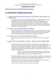
ISO/WD 12215-9⎯ M HD is the design heeling moment as defined in equation (13) (Nm)⎯ b c horizontal distance from centreline of the boat to chainplate, ( see figure 4) (m) (15)When chainplates at deck level are not at the same distance from centreline the average distance shall beused.9.3.2 Design and ultimate loads on rid and rig attachmenta: One set of spreaders b: Two set of spreaders c: Three set of spreaders d: Typical multihullFigure 4 — Typical transversal rig arrangementsa: Mast head rig with two sets of spreaders and fore and aft lowers b: Fractional rig with swept backspreaders d: Typical multihull rig16 © ISO 2004 — All rights reserved
ISO/WD 12215-9Figure 5 — Typical transversal rig arrangementsThe respective design loads and ultimate loads shall be calculated as follows:F rd = Fvkrdis the design load for the rig element, where k rd is given in Table 9 (N) (16)F ru = Fvkruis the ultimate load for the rig element; where k ru is given in Table 9 (N) (17)F cd = Fvkcdis the design load for the chainplate element, where k cd is given in Table 9 (N) (18)F cu = Fvkcuis the ultimate load for the chainplate element; where k cu is given in Table 9 (N) (19)F sd = Fvksdis the design load for the chainplate/ structure connection, k sd is given in Table 9 (N) (20)F su = Fvksuis the design load for the chainplate/ structure connection, k su is given in Table 9 (N) (21)Table 10 — Value of coefficients k id and k iuTransversal rig element and arrangementRatio between load and design Load on the rigLoad on Load connectionLoad on rigchainplate chainplate/StructureTransversal k rn k ru k cn k cu k sn k su1,00 2,00 1,50 3,00 2,50 5,00One set of spreader V1 transversal spreaders 0,45 0,90 0,68 1,35 1,13 2,25One set of spreader V1 aft sweapt spreaders 0,55 1,10 0,83 1,65 1,38 2,75One set of spreader D1 single 0,65 1,30 0,98 1,95 1,63 3,25One set of spreader D1 double fore/aft 0,33 0,66 0,50 0,99 0,83 1,652 or 3 sets of spreader V1 0,55 1,10 0,83 1,65 1,38 2,752 or 3 sets of spreader V1 aft sweaptspreaders 0,65 1,30 0,98 1,95 1,63 3,252 or 3 sets of spreader D1 single 0,40 0,80 0,60 1,20 1,00 2,002 or 3 sets of spreader D1 double fore/aft 0,25 0,50 0,38 0,75 0,63 1,25Longitudinal k rn k ru k cn k cu k sn k suHeadstay Masthead rig 0,45 0,90 0,68 1,35 1,13 2,25Headstay Fractional rig 0,40 0,80 0,60 1,20 1,00 2,00Headstay Masthead rig 0,45 0,90 0,68 1,35 1,13 2,25Backstay Masthead rig0,43lb/lh0,86lb/lh0,65lb/lh1,29lb/lh 1,1 lb/lh 4,2 lb/lhMat step k rn k ru k cn k cu k sn k suHeadstay Masthead rig 1,85 3,70 2,78 5,55 4,63 9,25Headstay Fractional rig 1,75 3,50 2,63 5,25 4,38 8,75For aft swept spreaders, the formula may be a function of la/lh© ISO 2004 — All rights reserved 17
ISO/WD 12215-99.3.3 Load on mast stepThe total vertical load at the mast step ( or the mast pillar if the mast is stepped on deck) is the sum of theloads induced by the transverse and the longitudinal rigging belonging to the mast in question.F md = Fvkmdis the design load on the mast, where k md is given in Table 9 (N) (22)F mu = Fvkmuis the ultimate load on the mast; where k mu is given in Table 9 (N) (23)F msd = Fvkmsdis the design load for the mast step, where k msd is given in Table 9 (N) (24)F msu = Fvkmsuis the ultimate load for the mast step; where k msu is given in Table 9 (N) (25)F = F k is the design load for the maststep/structure connection, k mssd is in Table 9 (N) (26)mssdvmssdF mssu = Fvkmssuis the design load for the maststep/structure connection, k mssu is in Table 9 (N) (27)9.4 Distribution of heeling moment between several mastsFor multiple mast rigs the maximum heeling moment of each mast is to be determined on basis of the sailarea moment, SAM, of each mast:SAMiWhere :nj 1( A d )= ∑ =⋅jj(Nm) (12)⎯ A is the sail area of specific sail on specific mast(m²)⎯ d = is the vertical distance from centre or lateral resistance (CLR) to aerodynamic centre of effort (COE)for specific sail on specific mast. The CLR may be taken as the canoe body draft Tc and COE as thegeometric centroid of the sail in the absence of more accurate data.(m)⎯ i = index for specific mast⎯ j = index for specific sail on specific mastriSAMi=n∑i= 1SAMiis the ratio of each mast's sail area moment to the total moment (13)This ratio shall be calculated for appropriate load cases which corresponding to normal use of the boat andmentioned in the owner's manual.9.4.1 For a mast with a maximum fraction f between 0,67 and 1.00:HM= 1 , 0 ⋅ RM(Nm) (14)9.4.2 For a mast with a maximum fraction f between 0.30 and 0.67:HM= 1 , 5⋅ f ⋅ RM(Nm) (15)18 © ISO 2004 — All rights reserved
ISO/WD 12215-910 <strong>Scantlings</strong> of chainplatesThe design and ultimate loads given in and Table 10 shall be used to determine the scantlings of chainplates.The load from the chainplates to the structure shall be essentially transferred via shear and bearing loads.Annex A gives an example of Stainless steel and Aluminium chainplates calculations.© ISO 2004 — All rights reserved 19
ISO/WD 12215-920 © ISO 2004 — All rights reserved
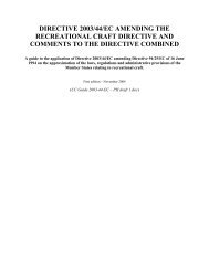
ISO/WD 12215-9Annex A(normative)Example of calculation of a chainplate and its connectionØ DMdPTa40°b c da: General dimensions b :Tensile stresses c: Bearing stresses d: Shear stressesFigure A 1 — Chainplate dimensions and loading layoutA.1 FormulasSFTT(P − E)σ d=Fd≥ 1,5is the safety factor for tensile stress (see Figure A1 b) (A1)SFBPD σ b=Fd≥ 1,5is the safety factor for bearing stress (see Figure A1 c) (A2)SFS2( M − 0,383 D)τ d=Fd≥ 1,5is the safety factor for shear (see Figure A1 d) (A3)NOTE0,383 =0,5 Cos 40. For aluminium D is the outer diameter of the bushing.These formula may be applied at design or ultimate level.The dimensions D,M,P,T are in mm, and are shown in Figure A1.© ISO 2004 — All rights reserved 21
ISO/WD 12215-9A.2 Pre-calculated values for typical chainplatesTables A1 and A2 gives some typical chainplate dimensions respectively for AISI 304 /316 and 5083Aluminium.*Wire ultimate loads and diameter are there for comparative value, but shall not be take as granted as theactual wire properties vary from one manufacturer to another.The approximation corresponds to rigid wire 1x19 for d w ≤10 mm and 1x37 above2dwRuRIG = 1500 0,76 π (N) for d w < 5 mm and42dwRuRIG = 1400 0,76 π (N) for d w ≥ 5 mm4Wire diameter 9, 11, 13 and 15 are theoretical values as there is no metric wire this size on the marker.For other types of wire, rod rigging, or fibre wires, the design load of the first column shall only be used.The three last columns give the ratio between the Ultimate strength of the chainplate compared to the ultimatestrength of the rig that shall be always > 1,5 for loading respectively in Tensile, Bearing and shear. (Thecomparison could have been made for design strength).A.2.1 AISI 304 or 316 Stainless steel chainplatesTable A 1 — Typical Chainplate dimensions and Safety factors for AISI 304 or 316 Stainless steelRIG SS Chainplate dimensions Ru Chainplate / Ru Rig >1,5Design Ultimate approx d D T P M Tensile Bearing Shearload load SS wire* Pin thickness width σ u (N/mm²) σ b (N/mm²) τ u (N/mm²)da N da N mm mm mm mm mm 500 900 289410 810 3 6 3 15 10 1,67 2,00 1,65720 1 430 4 8 4 20 13 1,68 2,01 1,601 120 2 240 5 8 5 22 15 1,56 1,61 1,541 510 3 010 6 10 6 25 18 1,50 1,79 1,632 050 4 090 7 12 7 30 20 1,54 1,85 1,522 680 5 350 8 12 8 35 24 1,72 1,61 1,673 390 6 770 9 13 10 38 26 1,85 1,73 1,794 180 8 360 10 14 10 40 28 1,56 1,51 1,565 060 10 110 11 17 14 42 30 1,73 2,12 1,886 020 12 030 12 18 14 46 32 1,63 1,89 1,697 060 14 120 13 20 16 50 35 1,70 2,04 1,798 190 16 380 14 22 16 55 40 1,61 1,93 1,789 400 18 800 15 25 18 60 42 1,68 2,15 1,7910 700 21 390 16 25 18 65 42 1,68 1,89 1,5715 090 30 170 19 27 20 75 50 1,59 1,61 1,5220 230 40 450 22 33 25 85 55 1,61 1,84 1,51A.3 Pre-calculated values for typical 5083 AluminiumAs the movements of the pin wears out the bore, it is highly recommended to fit a stainless steel bushingsleeve in the pin bore for pin diameter greater than 10 mm.In that case, the calculations shall be made with the diameter as Di the diameter of the outer bore22 © ISO 2004 — All rights reserved
ISO/WD 12215-9Table A 2 — Typical Chainplate dimensions and Safety factors for 5083 AluminiumDesign Ultimate approx d D Di Do T P M Tensile Bearing Shearload load SS wire* Pin SS bushing thickness width σ u (N/mm²) σ b (N/mm²) τ u (N/mm²)da N da N mm mm mm mm mm mm mm 275 495 159410 810 3 6 No bushing 6 15 10 3,06 2,20 1,81720 1 430 4 8 No bushing 8 20 12 1,85 2,22 1,591 120 2 240 5 10 No bushing 10 23 15 1,60 2,21 1,581 510 3 010 6 12 12 14 12 26 18 1,53 2,37 1,702 050 4 090 7 14 14 16 14 30 20 1,51 2,37 1,592 680 5 350 8 14 14 16 16 35 24 1,73 2,07 1,773 390 6 770 9 15 15 17 18 38 26 1,68 1,97 1,714 180 8 360 10 16 16 21 20 40 28 1,58 1,89 1,665 060 10 110 11 17 17 20 22 42 30 1,50 1,83 1,626 020 12 030 12 18 18 21 24 46 32 1,54 1,78 1,597 060 14 120 13 20 20 23 26 50 35 1,52 1,82 1,608 190 16 380 14 22 22 25 28 55 38 1,55 1,86 1,609 400 18 800 15 25 25 28 30 60 40 1,54 1,97 1,5410 700 21 390 16 25 25 25 32 65 42 1,65 1,85 1,5415 090 30 170 19 27 27 30 38 72 48 1,56 1,68 1,5120 230 40 450 22 33 33 36 42 88 60 1,57 1,70 1,56A.4 Example of calculation of the junction between the chainplate and the structure.A.4.1 Example of bolted junction.To be implemented at CD stageA.4.2 Example of welded junctionTo be implemented at CD stageA.4.3 Example of connection of a gusset with the hullTo be implemented at CD stage© ISO 2004 — All rights reserved 23