14_05 â Paper 11 â Three35 Presentation
14_05 â Paper 11 â Three35 Presentation
14_05 â Paper 11 â Three35 Presentation
- No tags were found...

You also want an ePaper? Increase the reach of your titles
YUMPU automatically turns print PDFs into web optimized ePapers that Google loves.
IntroductionCanterbury Earthquake repair bill approximately 10% GDP(cf 1995 Kobe 6.5%, 20<strong>11</strong> Japan earthquake and tsunami 4%)Insurance companies, governments, local bodies, building ownersand developers are keen on systems and technologies that focus ondamage avoidanceOne such technology is replaceable shear‐link EBF’s that are bolted.System supports premise of “damage avoidance”, but is really aRepair Impact Minimization (RIM) systemApplication of this technology was studied in 2010 PhD research atthe University of Toronto<strong>Three35</strong> project in Christchurch is first use of this technology in NZ
Performance of ConventionalEBF’s in Canterbury Earthquake SequenceGenerally steel framed buildings have performed well and haveexhibited damage threshold higher than expected compared withconcrete structures of similar agesChristchurch examples generally performed better than expected,exhibiting self‐centering propertiesIn contrast ‐ many prominent examples of well designed concretesystems that have generally satisfied their design requirements butunable to be repairedPerception that concrete structures difficult to fix, and that steelbuildings have generally performed “better”No significant changes made to current design practice forconventional EBF systems. Current design provisions readilyadaptable to low damage solutions
Performance of ConventionalEBF’s in Canterbury Earthquake SequenceWell‐detailed concrete column in Hotel Grand Chancellor following February20<strong>11</strong> Earthquake, and photo of active link section of HSBC Tower EBF(Photo on right courtesy of SCNZ)
University of Toronto Researchinto Replaceable-Link EBF’sPerformance of removable links was similar to conventional EBFswith links exhibiting good ductile behavior, developing stablerepeatable yieldingReplaceable‐links achieved and exceeded ductility acceptancecriteria of 0.08 rad inelastic link rotation and on‐site replaceabilityof the link sections was confirmed even in the presence of residualdeformations of 0.5% driftLoading protocol to AISC Seismic Provisions for Structural SteelBuildings, In addition, full‐scale dynamic testing research from theUniversity of Auckland showed that differences between pseudostaticand dynamic testing were negligible in similar test conditions
University of Toronto Researchinto Replaceable-Link EBF’sTest setup –frame at 1.7% drift, and total plastic link rotation of 0.<strong>11</strong>3 rad(Photo courtesy of University of Toronto)
University of Toronto Researchinto Replaceable-Link EBF’sTest links at 0.09 rad rotation, and 0.<strong>11</strong> rad rotation(Photos courtesy of University of Toronto)
<strong>Three35</strong> Project DescriptionTwo 3‐storey office buildings with area of approx 3,300m2 eachGravity system ‐ Rib&Infill precast floor system, composite steelbeams, steel columns, DHS purlins, UB raftersSeismic system ‐ 2 “D‐braced” and 1“K‐braced” frame (long), 2 “Dbraced”and 2 “K‐braced” frames (trans). EBF’s designed forstructural ductility factor of μ=3.0Buildings supported on steel screw‐piles to mitigate settlement andprovide assurance to the insurersIn accordance with damage avoidance principles ‐ suspendedground floor slab supported on concrete finger beams & piles toavoid issues with settlement due to liquefaction, and precast panelsat ends of building designed with limited base stiffness, anddetailed not to resist lateral loads
<strong>Three35</strong> Project DescriptionStreet level render of <strong>Three35</strong> project(Photo courtesy of Jasmax Architects)
Reason for Selection of EBF’swith Replaceable-LinksClient looking for innovative approaches to the design of structure.Reasons for the selection of the replaceable‐link EBF’s include:• Track record of ChCh EBF’s in and steel perceived as “better”performer• Easier insurance/finance approval for system• Marketing opportunities for tenants• Reduced downtime associated with repair• Constructability and erection time• Lower overall mass of structure and decreased loadsConcept of system discussed very early on in project
Reason for Selection of EBF’swith Replaceable-LinksErection of two‐storey “K‐bracedEBF, transported in two full‐height“halves” and bolted together on site
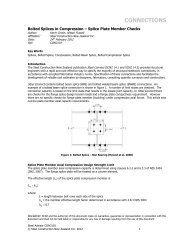
Design Parameters and MethodsDesign guidance a combination of that of existing EBFs and otherpublications and advice. Including:• NZS3404:1997• HERA report R4‐76• Design philosophies undertaken in conjunction with SCNZ andresearch from the University of Toronto• AISC publication “Base‐Plate and Anchor Rod Design”• SCNZ “Steel Advisor” publications• British Steel Construction Institute “Joints in Steel Construction‐ Moment Connections”• Associate Professor Charles Clifton from University ofAuckland• Canterbury Earthquakes Royal Commission Interim Report
Replaceable-Link EBF Design &Construction - Challenges & Recommendations• When considering replaceable‐links, RIM premise must betracked through job. This approach may result in additional costand requires increased collaboration with other consultants etc.Care required to eliminate yielding in all overstrength elements• Standardization of frame sizes and members is beneficial for bothdesigners and contractors and for replacement. K‐bracedconfiguration generally more efficient to reduce column sizingand collector beam combined actions• Bolted shear‐links suited to full height erection of half frames forbuildings up to five stories. K‐braced EBF’s easier to transportthan D‐braced as they are about half as high on truck
Replaceable-Link EBF Design &Construction - Challenges & Recommendations• Use of standard HERA connections and derivative document notapplicable to link endplate connections. To avoid unsatisfactoryyielding, endplates specifically modeled. Designers must includeany axial tension from the analysis into the shear‐link bolt design• Having standardized connections to link endplates would behugely beneficial for designers (similar to current HERAconnections)
Replaceable-Link EBF Design &Construction - Challenges & RecommendationsLink endplate modeling
Replaceable-Link EBF Design &Construction - Challenges & Recommendations• SCNZ suggested that shear keys be provided to retain comparablelateral stiffness of the tension and compression column bases toavoid overload of the column and braceShear key and details of hold‐down bolts
Replaceable-Link EBF Design &Construction - Challenges & Recommendations• More guidance on the design of shear keys for EBF baseplatesneeded• In addition to shear keys, it was recommended the HD boltsshould be partially tensioned. This required debonding of barsabove anchor plate level
Replaceable-Link EBF Design &Construction - Challenges & Recommendations• Baseplate must act as a “pin” to form mechanism. In keepingwith damage avoidance principles, important that detailsimulates a pin as much as possible.• Shear key and debonding are beneficial because:• Shear key promotes less bolts (less fixity)• Tensioning and debonding allows for some HD boly stretchand limited base rotation. Steelwork was isolated from floorslab above foundation, and steelwork in shear pocket wasdebonded to allow some rotationMore design guidance on achieving base rotation to baseplatesand shear keys would be useful to designers
Replaceable-Link EBF Design &Construction - Challenges & Recommendations• 80% reduction in collector beam moment outside link (forconventional EBF design) not applicable. Difficult to get “Dbraced”collector beams working under combined actionsDetails of link element to D‐braced EBF at level one ‐ note center linesdo not align at the end of the link endplate
Replaceable-Link EBF Design &Construction - Challenges & Recommendations• Design required upper limit of hot‐rolled section sizes andcustom fabricated sections, plates etc (non‐standard to ChChfabricators)• Designers should ensure fabricator can source specified sectionsor can fabricate the specified custom sections (requires closercollaboration but saves time)• To save time designers should check in advance that sizesspecified are standard and be aware that fillet welding of webs toflanges is generally standard practice. Should butt‐welding berequired, it should be checked that this can be achieved.• Designers must be aware that if using fabricated sections fromflame cut plate the α c factor in NZS3404 is affected
Replaceable-Link EBF Design &Construction - Challenges & Recommendations• Collector beam and brace centerline geometry need specificattention and link length derived from iterative process. Essentialthat the load path through the collector beam flange from thebrace into the beam web/endplate takes precedence overcentroids meeting at a pointExample of CDHB carparkEBF failure –note improperalignment of collector beamstiffener and brace flange(courtesy Greg MacRae)
Design and Construction -Challenges and RecommendationsHD bolt and shear key casting –note plytemplate (not steel) (left) and linkfabrication (right)
Replaceable-Link EBF Design &Construction - Challenges & Recommendations• Local fabricator subcontracted some welding which containeddefects requiring significant on‐site grinding and re‐welding• It appears that the NZ standard for weld testing NZS1554.1 needsto be aligned with AS2207• Extensive NDT and QA measures are required for a greaterproportion of critical welds compared to conventional EBF’s.• Importance of independent NDT weld testing and sound QAprocedures steelwork compliance cannot be overstated• Imperative that an independent compliance inspector beengaged on a project involving replaceable‐link EBF’s
Design and Construction -Challenges and Recommendations• Currently no formal requirements to check global flexuralcontinuity of EBF columns in a building. This may need to beaddressed in future EBF design guidelines• Designers should be aware that until the system becomes morecommonplace, there is likely to be extra detailed design effort fora bolted‐link EBF system compared to that for a conventional EBFdesign. Allowances should be made in programme for peerreview• Collaborative relationship between engineer, contractor, andsteel fabricator is likely to be required more intensively until thetechnology becomes more mainstream. Must allow for in fees
ConclusionsD‐Brace link (left) and close‐up view of link endplate (right)
Questions?