DXE-RTR-1 Receive Antenna Interface for Transceivers - N3UJJ
DXE-RTR-1 Receive Antenna Interface for Transceivers - N3UJJ
DXE-RTR-1 Receive Antenna Interface for Transceivers - N3UJJ
- No tags were found...

Create successful ePaper yourself
Turn your PDF publications into a flip-book with our unique Google optimized e-Paper software.
<strong>Receive</strong> <strong>Antenna</strong> <strong>Interface</strong><strong>for</strong> <strong>Transceivers</strong><strong>DXE</strong>-<strong>RTR</strong>-1Patent Pending<strong>DXE</strong>-<strong>RTR</strong>-1-INS Revision 4© DX Engineering 2010P.O. Box 1491 · Akron, OH 44309-1491Phone: (800) 777-0703 · Tech Support and International: (330) 572-3200Fax: (330) 572-3279 · E-mail: <strong>DXE</strong>ngineering@<strong>DXE</strong>ngineering.comFrom The <strong>N3UJJ</strong>.COM Document Library
Table of ContentsIntroduction 3“An Amateur Radio Dilemma” 3The DX Engineering Solution 3Features 4General In<strong>for</strong>mation 4<strong>DXE</strong>-<strong>RTR</strong>-1 <strong>Receive</strong> <strong>Antenna</strong> <strong>Interface</strong> <strong>for</strong> <strong>Transceivers</strong> - Front Panel 7<strong>DXE</strong>-<strong>RTR</strong>-1 <strong>Receive</strong> <strong>Antenna</strong> <strong>Interface</strong> <strong>for</strong> <strong>Transceivers</strong> - Rear Panel 8Internal Jumpers 9Connection Descriptions 9Receiving <strong>Antenna</strong> Spacing Guidelines 11Typical System Configurations 11Diagram 1A - Active <strong>Receive</strong> <strong>Antenna</strong> and Transmit <strong>Antenna</strong> 13Diagram 1B - Active <strong>Receive</strong> <strong>Antenna</strong> and Transmit <strong>Antenna</strong> with RX IN/OUT 14Diagram 2 - Active <strong>Receive</strong> <strong>Antenna</strong> and Transmit <strong>Antenna</strong> using High Power 15Additional System Configurations 16Diagram 3 -<strong>DXE</strong>-NCC-1 <strong>Receive</strong> <strong>Antenna</strong> Variable Phasing Controllerwith two Active <strong>Receive</strong> <strong>Antenna</strong>s18Diagram 4 - <strong>DXE</strong>-NCC-1 <strong>Receive</strong> <strong>Antenna</strong> Variable Phasing Controller with twoActive <strong>Receive</strong> <strong>Antenna</strong>s using high power to the transmit antenna.19Diagram 5 - Single Transmit <strong>Antenna</strong> System using a <strong>DXE</strong>-RPA-1 Preamplifier 20Diagram 6 -Single Transmit <strong>Antenna</strong> System using a <strong>DXE</strong>-RBS-1 Reversible Beverage<strong>Antenna</strong> System21Diagram 7 -Single Transmit <strong>Antenna</strong> with a <strong>DXE</strong>-RFS-TS2P <strong>Receive</strong> FourSquare Array Package22Diagram 8 -One Monoband or Multi-band Vertical Transmit <strong>Antenna</strong> using a<strong>DXE</strong>-ARAV2-1P Active <strong>Receive</strong> <strong>Antenna</strong> using the <strong>DXE</strong>-NCC-1 <strong>Receive</strong> 23<strong>Antenna</strong> Variable Phasing ControllerDiagram 9 -Classic T/R relay connections <strong>for</strong> separate Transmitter and <strong>Receive</strong>r witha Single Transmit <strong>Antenna</strong> System using a <strong>DXE</strong>-RPA-1 Preamplifier24Diagram 10 -Relay connections <strong>for</strong> separate Transceiver and <strong>Receive</strong>r with a SingleTransmit <strong>Antenna</strong> System using a <strong>DXE</strong>-RSC-2 Two-Port25Splitter/CombinerDiagram 11 - Relay connections <strong>for</strong> separate Transceiver and <strong>Receive</strong>r with an Active<strong>Receive</strong> <strong>Antenna</strong> and a Single Transmit <strong>Antenna</strong> System using a <strong>DXE</strong>- 26RSC-2 Two-Port Splitter/CombinerOperation 27Manual Updates 27Optional Items 28Technical Support 32Warranty 322From The <strong>N3UJJ</strong>.COM Document Library
IntroductionThe <strong>DXE</strong>-<strong>RTR</strong>-1 <strong>Receive</strong> <strong>Antenna</strong> <strong>Interface</strong> <strong>for</strong> <strong>Transceivers</strong> is a unique and simple, multi-purposerelay unit which automatically switches the RF output antenna connector on any HF transceiverbetween a receiving antenna system and a standard transmitting antenna. A manual override switchallows instantaneous switching between transmit and receive antennas.Designed specifically <strong>for</strong> HF transceivers which do not have a receive antenna input, the <strong>DXE</strong>-<strong>RTR</strong>-1 enables operators to safely enjoy the improved reception of low noise receiving antennasystem. Connection to Beverages, Reversible Beverages, Active <strong>Receive</strong> <strong>Antenna</strong>s, and otherreceiving antennas and accessories is now possible, only with the <strong>DXE</strong>-<strong>RTR</strong>-1.“An Amateur Radio Dilemma”The benefits of using separate receiving antennas <strong>for</strong> “low-band” HF operations have been known<strong>for</strong> many years. Enthusiasts of operations below 14 MHz have learned that typical transmittingantennas collect too much noise <strong>for</strong> reception, especially <strong>for</strong> DXing on the 160 and 80 meter bands.Un<strong>for</strong>tunately, <strong>for</strong> over three decades, only the most expensive HF transceivers have beenmanufactured with a separate receive antenna input. Even so, many older and newer “high-end”radios do not provide <strong>for</strong> switching their reception between a receive antenna and the defaulttransmit antenna, nor do they interrupt the receive input during transmit. To obtain a separatereceive antenna input, certain models required optional equipment or modules which are no longeravailable.For many Amateur Radio Operators, the joy of low-noise, low-band reception with a separatereceive antenna has been out of reach. Modern, “af<strong>for</strong>dable” HF transceivers have been designedwithout any provision <strong>for</strong> a receive antenna connection. Otherwise very capable transceivers, evenbrand new models, lack a built-in receive antenna port and relay system.The DX Engineering SolutionThe <strong>DXE</strong>-<strong>RTR</strong>-1 <strong>Receive</strong> <strong>Antenna</strong> <strong>Interface</strong> <strong>for</strong> <strong>Transceivers</strong>, offers a special antenna switchingsolution, that incorporates safeguards against accidental RF transmission into a receive antennasystem. The <strong>DXE</strong>-<strong>RTR</strong>-1 may be used <strong>for</strong> switching flexibility and to protect the receiver inputduring transmit <strong>for</strong> those transceivers that are so equipped.Typical homebrew and commercial transmit/receive (T/R) relays, and other receive switchingsolutions on the market, offer little or no protection to the receive antenna equipment. Transmittedenergy could damage receiving equipment if keying and timing errors or power loss occurs.The <strong>DXE</strong>-<strong>RTR</strong>-1 is a new HF relay system that allows reception only if the unit is powered and thekeying line from the transceiver is connected. As soon as the transceiver is keyed or the <strong>DXE</strong>-<strong>RTR</strong>-1 loses power at any time, the RF output from the transceiver is automatically diverted to thetransmit antenna connection. A very fast acting (about 4 ms) 200 watt RF capable relay in the<strong>DXE</strong>-<strong>RTR</strong>-1 diverts the transceiver output quickly enough <strong>for</strong> QSK operation (full break-in CW)3From The <strong>N3UJJ</strong>.COM Document Library
while listening to a receive antenna. The <strong>DXE</strong>-<strong>RTR</strong>-1 also allows instantaneous receivecomparisons between the receive antenna and the transmit antenna, with a convenient three-positionfront panel switch. Indicator LEDs (Light Emitting Diodes) on the front panel allow the user todetermine at a glance if the unit is properly powered and if the receive or transmit antenna isselected <strong>for</strong> reception and when the unit is keyed <strong>for</strong> transmission.Features• Attractive, Heavy Stainless Steel Enclosure that won't slide on your desk• Front Panel LED Status Indicators and Manual Override Switch• 200 Watt Transmit Switching Capability• Supports CW full break in (QSK)• <strong>Receive</strong> <strong>Antenna</strong> Inputs and Outputs use RCA phono and Type F connectors <strong>for</strong> safety• Main <strong>Antenna</strong> and Radio Connectors are SO-239 <strong>for</strong> ease of installation• Safe switching - automatically connects radio to transmit antenna when dc power is off• Hot switching lockout – disconnects receive antenna during transmit mode• Adds protection and antenna switching flexibility - <strong>for</strong> transceivers with receive portsThe <strong>DXE</strong>-<strong>RTR</strong>-1 <strong>Receive</strong> <strong>Antenna</strong> <strong>Interface</strong> <strong>for</strong> <strong>Transceivers</strong> is an attractive station accessory,housed in a heavy, stainless-steel enclosure which matches other DX Engineering stationaccessories. Cable connections to the <strong>DXE</strong>-<strong>RTR</strong>-1 are made entirely on the back panel, and allswitches and indicators are on the front panel, <strong>for</strong> a clean, easy-to-use installation.General In<strong>for</strong>mationThe <strong>DXE</strong>-<strong>RTR</strong>-1 <strong>Receive</strong> <strong>Antenna</strong> <strong>Interface</strong> <strong>for</strong> <strong>Transceivers</strong> is the accessory that allows ownersof transceivers which lack a receive antenna input to safely enjoy optional receive enhancingequipment. The DX Engineering <strong>DXE</strong>-RPA-1 <strong>Receive</strong> Pre-Amplifier may be used in-line on areceive antenna. The <strong>DXE</strong>-NCC-1 <strong>Receive</strong> <strong>Antenna</strong> Variable Phasing Unit and the <strong>DXE</strong>-AAPS-1Active <strong>Antenna</strong> Phasing System are now available <strong>for</strong> operations <strong>for</strong> RX ANT Input deprivedradios. The <strong>DXE</strong>-<strong>RTR</strong>-1 may be combined with the <strong>DXE</strong>-TVSU-1A Time Variable Sequence Unit<strong>for</strong> high power operations at stations where the receive antenna is physically close to the transmitantenna and <strong>for</strong> status indication of keying.Old and new transceivers alike can benefit from the use of a high per<strong>for</strong>mance, low-noise preamplifierto enhance reception. The <strong>DXE</strong>-RPA-1 <strong>Receive</strong> Pre-Amplifier offers dynamic range andthird order intercept per<strong>for</strong>mance that exceeds most top dollar transceivers. As requested by manyAmateurs worldwide, the receive only <strong>DXE</strong>-RPA-1 <strong>Receive</strong> Pre-Amplifier may now be used inlinesafely <strong>for</strong> improved reception with a transmitting antenna, when connected with the <strong>DXE</strong>-<strong>RTR</strong>-1.For enthusiasts who wish to use a favorite transceiver as a receiver only, now using an RF outputconnection to a receive pre-amplifier and antenna and can be virtually worry free. Accidentaltransmission through the receive antenna or receive pre-amplifier need not cause concern with aproperly connected <strong>DXE</strong>-<strong>RTR</strong>-1.4From The <strong>N3UJJ</strong>.COM Document Library
Many owners of transceivers that have receive ports are choosing to use the <strong>DXE</strong>-<strong>RTR</strong>-1. For theseoperators it offers two benefits. First and <strong>for</strong>emost, the <strong>DXE</strong>-<strong>RTR</strong>-1 can protect the front end of thetransceiver with automatic disconnection of the receive input during transmit, preserving fast CWbreak-in operation (QSK) with a 4 ms response time. Second, the <strong>DXE</strong>-<strong>RTR</strong>-1 offers a simple andhandy way to toggle between listening to receive and transmit antennas with a front panel switch.Most high-end transceivers, old and new, offer a receive antenna input that DOES NOT interruptRF or switch off during transmit, even though the receiver is muted, very quickly in full break-inCW operation. This is a design feature which allows an operator to listen to a receive antenna,located a sufficient distance away from the transmit antenna to prevent receiver front end damage,allowing very fast QSK operations. However, most Amateurs who own this type of radio do nothave access to the real estate <strong>for</strong> the required antenna separation to support this type of operation.Un<strong>for</strong>tunately, several hams have discovered these facts the hard way, after unintentionally blowingthe front end of their expensive transceiver with transmitted RF riding in on their receive antennafeedline. Also, on many transceivers, connection of a receive antenna to the RX (antenna) IN portrequires removal of the “RX OUT to RX IN” jumper patch cable, and then the transmit antennacannot be heard. Recommendations <strong>for</strong> external relays and other devices have not addressed theneed <strong>for</strong> protection as well as switching options. The <strong>DXE</strong>-<strong>RTR</strong>-1 fills this need with an attractiveand versatile accessory.For those who want to use a separate receiver or use a second transceiver as a receiver and interruptthe receive antenna feedline when transmitting, the <strong>DXE</strong>-<strong>RTR</strong>-1 may be used as a T/R relay. Also,monitoring the transmitting antenna with a second receiver while operating the main transceiverwith a receive antenna (SO2R application) is possible with the <strong>DXE</strong>-<strong>RTR</strong>-1.The <strong>DXE</strong>-<strong>RTR</strong>-1 may also be used with an optional <strong>DXE</strong>-RSC-2 Two-Port Splitter/Combiner toshare a transmit antenna between two transceivers, with only one used <strong>for</strong> transmitting, or betweena transceiver and a receiver.Standard relays and coaxial relays that are used in a typical default receive T/R system are prone tokeying timing problems which can result in damaging receiver front-ends due to pulses or hotswitching. The <strong>DXE</strong>-<strong>RTR</strong>-1 solves that problem <strong>for</strong> vintage radio collectors and operators. Used asa traditional T/R relay, it switches a transmit antenna between a receiver and a transmitter with anoutput of up to 200 watts. The <strong>DXE</strong>-<strong>RTR</strong>-1 offers complete protection and high speed (4 ms)receive to transmit transfer. The <strong>DXE</strong>-<strong>RTR</strong>-1 is a superior solution to old, slow T/R relays, and itallows the safe use of an optional receive preamplifier.Detailed diagrams of the following applications and accessory connections are included in thismanual.Connecting a transceiver that does not have a receive antenna input to:• <strong>DXE</strong>-ARAV2-1P Active <strong>Receive</strong> <strong>Antenna</strong>• <strong>DXE</strong>-ARAV2-1P Active <strong>Receive</strong> <strong>Antenna</strong> and transmit <strong>Antenna</strong> using high power• <strong>DXE</strong>-NCC-1 <strong>Receive</strong> <strong>Antenna</strong> Variable Phasing Controller with two <strong>DXE</strong>-ARAV2-1PActive <strong>Receive</strong> <strong>Antenna</strong>s• <strong>DXE</strong>-NCC-1 <strong>Receive</strong> <strong>Antenna</strong> Variable Phasing Controller with two <strong>DXE</strong>-ARAV2-1PActive <strong>Receive</strong> antennas using high power to the transmit antenna.• Single transmit antenna system using a <strong>DXE</strong>-RPA-1 Preamplifier• Single transmit antenna system using a <strong>DXE</strong>-RBS-1 Reversible Beverage <strong>Antenna</strong> System5From The <strong>N3UJJ</strong>.COM Document Library
• Single transmit antenna with a <strong>DXE</strong>-RFS-TS2P <strong>Receive</strong> Four Square Array Package• One DX Engineering Monoband or Multi-band Vertical transmit antenna using a <strong>DXE</strong>-ARAV2-1P Active <strong>Receive</strong> <strong>Antenna</strong> with the <strong>DXE</strong>-NCC-1 <strong>Receive</strong> <strong>Antenna</strong> VariablePhasing ControllerConnecting a transceiver that has a receive antenna input and receive output:• For any receive antenna system interruption of receive antenna feedline during transmit• For the versatility of switching between listening to either the receive or transmit antennaConnecting a transmitter and receiver to the same antenna system:• Classic T/R relay connections <strong>for</strong> separate Transmitter and <strong>Receive</strong>r with a Single Transmit<strong>Antenna</strong> System using a <strong>DXE</strong>-RPA-1 PreamplifierConnecting two transceivers, one used <strong>for</strong> receive only, to the same transmit antenna, <strong>for</strong>simultaneous reception.• Using an optional <strong>DXE</strong>-RSC-2 Two-Port Splitter/Combiner, a transmit antenna can beshared <strong>for</strong> dual receiving.Connecting two transceivers, one used <strong>for</strong> receive only, to the same active receive antenna, <strong>for</strong>simultaneous reception.• Using an optional <strong>DXE</strong>-RSC-2 Two-Port Splitter/Combiner, a transmit antenna can beshared <strong>for</strong> dual receiving.Other uses of the <strong>DXE</strong>-<strong>RTR</strong>-1 are possible but not detailed in this manual:• Connecting a non-active receive only antenna to a transceiver and transmitting antennasystem• Connecting a main transceiver and a second transceiver <strong>for</strong> single operator-two radio(SO2R) contesting.Given the nature of Amateur Radio Operators and their interest in experimentation, there may bemany other options available when using the <strong>DXE</strong>-<strong>RTR</strong>-1 <strong>Receive</strong> <strong>Antenna</strong> <strong>Interface</strong> <strong>for</strong><strong>Transceivers</strong>.6From The <strong>N3UJJ</strong>.COM Document Library
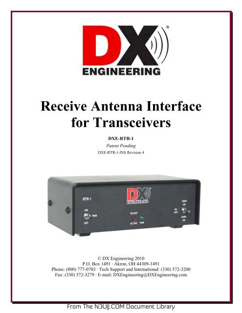
<strong>DXE</strong>-<strong>RTR</strong>-1 <strong>Receive</strong> <strong>Antenna</strong> <strong>Interface</strong> <strong>for</strong> <strong>Transceivers</strong> - Front PanelFigure 1 PWR ON-OFFToggle Switch - <strong>DXE</strong>-<strong>RTR</strong>-1 power on and off. +12 Vdc power is supplied via the rear panelcenter positive connector. RX ANT - ACTIVE indicatorOne Red LED (Light Emitting Diode) illuminates to indicate the <strong>DXE</strong>-<strong>RTR</strong>-1 is in the receivemode. This LED extinguishes when MAIN ON is selected or when keyed with RX ANTselected. PWR indicatorOne Green LED (Light Emitting Diode) illuminates to indicate the <strong>DXE</strong>-<strong>RTR</strong>-1 is poweredand turned on. MAIN ON - RX ANT - MAIN ON toggle switchThree position (On-On-plus Momentary) provides manual control of the <strong>DXE</strong>-<strong>RTR</strong>-1 antennaselections.MAIN ON (up) - Manually switches RADIO to the MAIN ANT <strong>for</strong> receiving with thetransmitting antenna. RADIO remains connected to MAIN ANT during transmit.RX ANT (center) - Switches the RADIO to the RX ANT <strong>for</strong> receive mode and allowsautomatic switching of the RADIO to the MAIN ANT during transmit.MAIN ON (momentary on when pressed down) - Manually switches RADIO to MAIN ANTmomentarily <strong>for</strong> a fast check of reception on the transmitting MAIN ANT.7From The <strong>N3UJJ</strong>.COM Document Library
<strong>DXE</strong>-<strong>RTR</strong>-1 <strong>Receive</strong> <strong>Antenna</strong> <strong>Interface</strong> <strong>for</strong> <strong>Transceivers</strong> - Rear PanelFigure 2 TRANSMIT GROUNDIsolated RCA connector - Keying line connection from transceiver or sequencer (groundingkeying line only) <strong>for</strong> automatic relay switching of RADIO from the RX ANT IN to the MAINANT. This connection to the transceiver is required to enable reception on a receive antenna;RX ANT through to RADIO with front panel MAIN ON/RX ANT switch in RX ANT position.Note: If the keying line is shared (using a "Y" adapter) with an amplifier or amplifier interfacebuffer, then precautions should be taken to be certain that the transceiver to <strong>DXE</strong>-<strong>RTR</strong>-1connection is not interrupted.If the keying line connection from the transceiver to the TRANSMIT GROUND connector on the<strong>DXE</strong>-<strong>RTR</strong>-1 is lost, transmitted RF may cause damage to the <strong>DXE</strong>-<strong>RTR</strong>-1 or receiving equipment.This connector MUST be connected to the grounded-on-transmit transceiver keyingline, cable shield to radio chassis ground, and the RADIO connector must be connected tothe transceiver RF connector, cable shield to radio chassis ground, to enable receive mode.Positive voltage keying will not key the <strong>DXE</strong>-<strong>RTR</strong>-1 properly.Damage to the <strong>DXE</strong>-<strong>RTR</strong>-1 could occur by attempting to use positive voltage keying.Review your transceiver operation manual carefully. <strong>Transceivers</strong> with positive keyingonly must be connected to an interface buffer to provide grounding-on-transmit keying. RADIOSO-239 connector - Transmit and receive RF connection to the transceiver or connection totransmitter RF connector. Maximum 200 Watts transmit with MAIN ANT connected to asuitable antenna or load. Connected, by default, to the MAIN ANT IN connector when the<strong>DXE</strong>-<strong>RTR</strong>-1 is not powered or the MAIN ANT/RX ANT switch in the MAIN ANT position.8From The <strong>N3UJJ</strong>.COM Document Library
MAIN ANT INSO-239 connector - RF connection to a suitable transmit antenna or load. Connected, bydefault, to the RADIO connector when the <strong>DXE</strong>-<strong>RTR</strong>-1 is not powered or the MAIN ANT/RXANT switch in the MAIN ANT position. Connection <strong>for</strong> high end transceiver "RX OUT" tomonitor transmit antenna through <strong>DXE</strong>-<strong>RTR</strong>-1. Details in Diagram 1B and text. MAIN ANT OUTRCA type connector and F-Connector (in parallel) - Output <strong>for</strong> special applications, receiveonly connection of MAIN ANT during receive mode only. Used <strong>for</strong> transmit antennamonitoring and pre-amplification or phasing purposes only. Disconnected during transmit orwhen unit is switched to MAIN ANT. See Diagrams 5 and 8. RX ANT INRCA type connector and F-Connector (in parallel) - Input <strong>for</strong> receive only antenna, or from areceive only device. May accept output from a <strong>DXE</strong>-RPA-1 <strong>Receive</strong> Preamplifier, or from a<strong>DXE</strong>-NCC-1 <strong>Receive</strong> <strong>Antenna</strong> Variable Phasing Controller. 12 VDCA 2.1 mm power cord is supplied with unit. The wire with the white stripes is the +12 Vdc.Outer Connection is GROUNDCenter Pin is +12 VDC.If station power is used, it must be +12 Vdc at 1 amp (fused) minimum. An optional<strong>DXE</strong>-PSW-12D1A 120 Vac 60 Hz to 12 Vdc 1 Amp, fused wall trans<strong>for</strong>mer supplyis available.Internal JumpersThere are two internal jumpers set to factory default positions. HD1 and HD2 are jumpered bydefault to the top two pins towards the HD1 and HD2 lettering on the printed circuit board <strong>for</strong>proper operation as shown in Figure 3. HD1 and HD2 are reserved <strong>for</strong> possible future options.Connection DescriptionsFigure 3 - Internal Jumpers HD1 and HD2The diagrams included in this manual demonstrate the wide variety of specific connections that arepossible with the <strong>DXE</strong>-<strong>RTR</strong>-1, truly a multi-purpose device. These connections are simple andstraight<strong>for</strong>ward and do not require advanced electronics skill.9From The <strong>N3UJJ</strong>.COM Document Library
Connect a regulated station power supply which provides a 1 A fused 12 Vdc to the <strong>DXE</strong>-<strong>RTR</strong>-1power connector on the back panel. With the included 2.1 mm power cord, the power connectormust be wired center positive. If a station power supply is not available, connect the optional <strong>DXE</strong>-PSW-12D1A Wall Trans<strong>for</strong>mer.Typical interconnections between the <strong>DXE</strong>-<strong>RTR</strong>-1, the transceiver, antennas and accessoryequipment are made with commonly available or easily made patch cords. Plans should be made tolocate the <strong>DXE</strong>-<strong>RTR</strong>-1 close to the transceiver, so instant reception antenna changes may be madewith the front panel switch.<strong>Receive</strong> only connections must be made with either male RCA phono style patch cords or with maleF connector cables. Custom length cables with F-Connectors installed can be supplied by <strong>DXE</strong>ngineering. If RCA phono style patch cords are used, high quality connectors should be selected<strong>for</strong> this low-noise RF application. Inexpensive audio cables may not be suitable. RCA Phono and F-Connectors are used on DX Engineering receive devices to help prevent accidental connection totransmitting connectors.Transmitting RF connections on the <strong>DXE</strong>-<strong>RTR</strong>-1, from RADIO to the transceiver and from MAINANTENNA to the transmitting antenna system, tuner or amplifier are made with standard PL-259patch cables in lengths that permit locating the equipment in their proper operating positions.Custom length cables with PL-259 connectors installed can be supplied by DX Engineering.The TRANSMIT GROUND keying line connection to the <strong>DXE</strong>-<strong>RTR</strong>-1 must be made to enablereception with a connected receive antenna or accessory. Keying line connection from transceiveror sequencer (grounding keying line only) <strong>for</strong> automatic relay switching of RADIO from the RXANT IN to the to MAIN ANT.This connection may be shared with an amplifier-transceiver interface buffer keying input. Thediagrams in this manual show connections to transceivers with grounded-on-transmit keying lineonly.Note: If the keying line is shared (using a "Y" adapter) with an amplifier or amplifier interfacebuffer, then precautions should be taken to be certain that the transceiver to <strong>DXE</strong>-<strong>RTR</strong>-1connection is not interrupted.If the keying line connection from the transceiver to the TRANSMIT GROUND connector on the<strong>DXE</strong>-<strong>RTR</strong>-1 is lost, transmitted RF may cause damage to the <strong>DXE</strong>-<strong>RTR</strong>-1 or receiving equipment.The TRANSMIT GROUND keying line connector MUST be connected to a groundedon-transmittransceiver keying line, cable shield to radio chassis ground, and the RADIOconnector must be connected to the transceiver RF connector, cable shield to radio chassisground, to enable receive mode.Positive voltage keying will not key the <strong>DXE</strong>-<strong>RTR</strong>-1 properly.Damage to the <strong>DXE</strong>-<strong>RTR</strong>-1 could occur by attempting to use positive voltage keying.Review your transceiver operation manual carefully. <strong>Transceivers</strong> with positive keyingonly, must be connected to an interface buffer to provide grounding-on-transmit keying.10From The <strong>N3UJJ</strong>.COM Document Library
Receiving <strong>Antenna</strong> Spacing GuidelinesThe overall benefits that receiving antenna offer is less noise. Weak signals can be heard on adedicated receive antenna because it rejects noise and strong stations by virtue of its design, size,directivity and lower sensitivity.There<strong>for</strong>e, placement of a receiving antenna is very important. Normally, excellent results areachieved by placing a receive antenna in a low noise environment. If possible, receive antennasshould be located at least 1/2-wavelength away from noise sources and noise re-radiating antennas.Houses, other metal or structures containing metal, metal fencing, towers and transmitting antennascan introduce noise into a receive antenna by proximity which may reduce the effectiveness of areceive antenna.However, in many cases, the physical space required <strong>for</strong> the ideal receive antenna installation is notavailable to the average back yard. The following diagrams (1-7) of typical and special systemconfigurations show absolute minimum spacing between transmitting and DX Engineering Active<strong>Receive</strong> <strong>Antenna</strong>s. For optimal per<strong>for</strong>mance, greater spacing is recommended <strong>for</strong> better receptionresults.Diagram 8 shows phasing of a mono-band or multi-band vertical antenna using a <strong>DXE</strong>-ARAV2-1PActive <strong>Receive</strong> Vertical <strong>Antenna</strong> with the <strong>DXE</strong>-NCC-1 <strong>Receive</strong> <strong>Antenna</strong> Phasing Controller. Thespacing described is 1/4 to 1/2-wavelength between the transmit antenna and the Active <strong>Receive</strong><strong>Antenna</strong>. This distance is based on optimal per<strong>for</strong>mance of the equipment described.For in-depth receiving antenna system in<strong>for</strong>mation, please consult the ARRL <strong>Antenna</strong> Book orON4UN's Low Band DXing book.Typical System ConfigurationsIn most cases, the operator will purchase the <strong>DXE</strong>-<strong>RTR</strong>-1 because they want to use a receiveantenna on a transceiver which lacks a receive antenna input. See the text below and use Diagram1B <strong>for</strong> an example using the <strong>DXE</strong>-<strong>RTR</strong>-1 with a transceiver having a <strong>Receive</strong> Input and Output.All transceivers under 200 watts output may be connected to the <strong>DXE</strong>-<strong>RTR</strong>-1 as is shown inDiagram 1A, and all other Diagrams 2 through 9, even if it has a receive antenna input.Diagram 1A illustrates the positions and connections to a standard transceiver <strong>for</strong> optional receiveenhancement products from DX Engineering. A simple Beverage antenna or receiving loop antennamay be connected directly to the RX ANT connector on the <strong>DXE</strong>-<strong>RTR</strong>-1. If a single <strong>DXE</strong>-ARAV2-1P Active <strong>Receive</strong> Vertical is purchased, then the included powering device, model <strong>DXE</strong>-FVI-1, is placed in-line in the shack between the Active <strong>Receive</strong> Vertical and the RX ANT input, orbetween the optional <strong>DXE</strong>-RPA-1 <strong>Receive</strong> Preamplifier and the <strong>DXE</strong>-RFCC-1 <strong>Receive</strong> FeedlineCurrent Choke.Diagram 1B illustrates how to connect the <strong>DXE</strong>-<strong>RTR</strong>-1 to a transceiver using available receiveinput and output connectors. For in<strong>for</strong>mational example purposes, here is a partial listing of thetransceivers that can benefit from connections with the <strong>DXE</strong>-<strong>RTR</strong>-1: Yaesu FT-1000 series, FT-1000MP/ MKV series, FT-2000 series and FT-9000 series; Icom IC-7800, IC-7700, IC-7600, IC-765, IC-761 and IC-781.Most high-end transceivers, old and new, offer a receive antenna input that DOES NOT interrupt or11From The <strong>N3UJJ</strong>.COM Document Library
switch off during transmit even though the receiver is muted. Also, on many transceivers,connection of a receive antenna to the RX IN port means that the RX OUT to RX IN jumper patchcord must be removed. Then the transmit antenna cannot be heard. For operators of these high-endtransceivers, the <strong>DXE</strong>-<strong>RTR</strong>-1 offers two benefits. First and <strong>for</strong>emost, it can protect the front endwith automatic disconnection of the receive input, preserving very fast break-in operation (fullQSK) with 4 ms response. Second, the <strong>DXE</strong>-<strong>RTR</strong>-1 offers a simple and handy way to togglebetween listening to the receive and transmit antennas with a front panel switch.The <strong>DXE</strong>-<strong>RTR</strong>-1 RX ANT connector is used <strong>for</strong> the receive antenna system signals. Thetransceiver RF output is connected to the transmit antenna or amplifier. The transceiver amplifierkeying line must be connected to the <strong>DXE</strong>-<strong>RTR</strong>-1 TRANSMIT GROUND connector to enablereception of the receive antenna signal. Customer supplied RF patch cords must be used to connectto the SO-239 RADIO and MAIN ANT IN ports on the <strong>DXE</strong>-<strong>RTR</strong>-1 to the RX IN and OUT portson a transceiver, respectively, replacing the existing jumper patch cable. In most cases these aresimply two patch cords with PL-259s on one end and male RCA phono plugs on the other end. Thisconnection will never allow transmitted RF into the front end of the transceiver. Since the RX OUTcarries only the received transmit antenna signals, the <strong>DXE</strong>-<strong>RTR</strong>-1 will allow monitoring of eitherthe receive or transmit antenna as described in this manual. This connection scheme is applicable<strong>for</strong> the radios listed above, as well as others not listed, which offer RX IN and OUT. Thistransceiver connection scheme may also be adapted <strong>for</strong> use with any of the diagramed systemconfigurations. If your transceiver has only a receive antenna input but no RX OUT, use thestandard connection methods depicted in Diagrams 1a and 2 through 9.Diagram 2 shows a standard transceiver connection arrangement, with the addition of a typical RFamplifier used on the transceiver output <strong>for</strong> high power operations. The <strong>DXE</strong>-<strong>RTR</strong>-1 and a keyedon-groundamplifier may be able to share the same grounding keying line from the transceiver, butthe use of an optional amplifier keying interface buffer is recommended. Do not share the keyingline of the <strong>DXE</strong>-<strong>RTR</strong>-1 with an older amplifier that uses high voltage relays.NOTE: The <strong>DXE</strong>-<strong>RTR</strong>-1 may never be used on the output of an RF amplifier.MAXIMUM RF power allowed through the unit is 200 watts.Note: If the keying line is shared (using a "Y" adapter) with an amplifier or amplifier interfacebuffer, then precautions should be taken to be certain that the transceiver to <strong>DXE</strong>-<strong>RTR</strong>-1connection is not interrupted.If the keying line connection from the transceiver to the TRANSMIT GROUND connectoron the <strong>DXE</strong>-<strong>RTR</strong>-1 is lost, transmitted RF may cause damage to the <strong>DXE</strong>-<strong>RTR</strong>-1 orreceiving equipment.The TRANSMIT GROUND keying line connector MUST be connected to a grounded-ontransmittransceiver keying line, cable shield to radio chassis ground, and the RADIOconnector must be connected to the transceiver RF connector, cable shield to radio chassisground, to enable receive mode.Positive voltage keying will not key the <strong>DXE</strong>-<strong>RTR</strong>-1 properly. Damage to the <strong>DXE</strong>-<strong>RTR</strong>-1could occur by attempting to use positive voltage keying. Review your transceiver operationmanual carefully. <strong>Transceivers</strong> with positive keying only must be connected to an interfacebuffer to provide grounding-on-transmit keying.12From The <strong>N3UJJ</strong>.COM Document Library
Diagram 1A - Active <strong>Receive</strong> <strong>Antenna</strong> and Transmit <strong>Antenna</strong>Allows use of an active receive antenna with the added receive signalstrength using a pre-amplifier.Minimum 1/10 Wavelength Apart(see text on <strong>Receive</strong> <strong>Antenna</strong> Spacing Guidelines)<strong>DXE</strong>-ARAV2-1 P<strong>Receive</strong><strong>Antenna</strong>Transmit<strong>Antenna</strong>Notes:For clairity - not all connections are shownOptional Items: Refer to product manuals <strong>for</strong>detailed connections<strong>Receive</strong> FeedlineCurrect ChokeVoltageInjector<strong>Receive</strong>r Preamplifier<strong>DXE</strong>-RPA-1<strong>DXE</strong>-RFCCI l <strong>DXE</strong>-FVI-1 <strong>DXE</strong>-PSW-1201 A._--~~ ·~--~ f'f""iP"~--+12 Vdc1A Fused+12 Vdc1A Fused<strong>DXE</strong>-<strong>RTR</strong>-1
Diagram 1B - Active <strong>Receive</strong> <strong>Antenna</strong> and Transmit <strong>Antenna</strong>Allows use of an active receive antenna with the added receive signalstrength using a pre-amplifier connected to a transceiver equippedwith RX INPUT and OUTPUT ports.~ Minimum 1/10 Wavelength Apart ...(see text on <strong>Receive</strong> <strong>Antenna</strong> Spacing Guidelines)<strong>DXE</strong>-ARA V2-1 P<strong>Receive</strong><strong>Antenna</strong>Transmit<strong>Antenna</strong>Notes:For clairity - not an connections are shownOptional Items: Refer to product manuals <strong>for</strong>detailed connections<strong>Receive</strong> FeedlineCurrect Choke<strong>DXE</strong>-RFCC.... I '-~- - ~~~~VoltageInjector<strong>DXE</strong>-FVI-1l'r"e"~ ....<strong>Receive</strong>r Preamplifier<strong>DXE</strong>-RPA-1<strong>DXE</strong>-PSW-12D1A+12 Vdc1A Fused+12 Vdc1A Fused<strong>DXE</strong>-<strong>RTR</strong>-1@.~ .........PI<strong>DXE</strong>-PSW-1201 A+12 VdcThese adapter patchcables are customersupplied with PL-259sand connectors thatmatch the RX IN/RXOUTof the transceiver in placeof the existing jumperIC-7600shownOptional items shown include: <strong>DXE</strong>-ARAV2-1P Active Vertical <strong>Receive</strong> <strong>Antenna</strong> w/ Internal <strong>Antenna</strong>Disconnect Relay. <strong>DXE</strong>-RFCC <strong>Receive</strong> Feedline Current Choke, <strong>DXE</strong>-FVI-1 Voltage Injector, <strong>DXE</strong>-RPA-1 <strong>Receive</strong>r Preamplifier and <strong>DXE</strong>-PSW-12D1A +12 Vdc fused 1 amp wall trans<strong>for</strong>mer.14From The <strong>N3UJJ</strong>.COM Document Library
Additional System ConfigurationsDiagram 3 shows an exciting new receiving application. The <strong>DXE</strong>-<strong>RTR</strong>-1 <strong>Receive</strong> <strong>Antenna</strong><strong>Interface</strong> <strong>for</strong> <strong>Transceivers</strong> now allows owners of transceivers which lack a receive antenna input touse a phased receive antenna array. This diagram shows the connections <strong>for</strong> use of the <strong>DXE</strong>-AAPS-1P Electronically Rotatable <strong>Receive</strong> <strong>Antenna</strong> System, which consists of two <strong>DXE</strong>-ARAV2-1PActive Vertical <strong>Receive</strong> <strong>Antenna</strong>s with Internal <strong>Antenna</strong> Disconnect Relays and the <strong>DXE</strong>-NCC-1<strong>Receive</strong> <strong>Antenna</strong> Variable Phasing Controller using the <strong>DXE</strong>-<strong>RTR</strong>-1 <strong>Receive</strong> Transmit Relay.Diagram 4 details the connections to optional equipment required when operating high power andusing the <strong>DXE</strong>-AAPS-1P Electronically Rotatable <strong>Receive</strong> <strong>Antenna</strong> System. The addition of the<strong>DXE</strong>-TVSU-1A Time Variable Sequencer Unit will produce the correct keying of all devices, toprotect the Active <strong>Receive</strong> <strong>Antenna</strong>s from high power RF damage. The <strong>DXE</strong>-<strong>RTR</strong>-1 providesconnection to the transceiver which does not offer a receive antenna input.Diagram 5 includes the exceptional <strong>DXE</strong>-RPA-1 <strong>Receive</strong> Preamplifier in-line with the main(transmit) antenna. For many years Amateurs have been requesting a method to employ a receivingdevice on their transceivers which lack a built-in preamplifier. The <strong>DXE</strong>-<strong>RTR</strong>-1 provides thisconnection option. Instantaneous receive comparisons between 'preamplifier in' and 'preamplifierout' are easily accomplished using the <strong>DXE</strong>-<strong>RTR</strong>-1 MAIN ON - RX ANT - MAIN ON toggleswitch.Receiving with the transmitting antenna on a second transceiver or receiver while operating with themain transceiver connected to a receive antenna is a common contesting application known asSingle Operator – Two Radios (SO2R). This is now easily accomplished by connecting the MAINANT OUT line to the input of the second radio. Reception with the transmitting antenna is safelyinterrupted during main transceiver transmissions.Diagram 6 demonstrates another common use <strong>for</strong> the <strong>DXE</strong>-<strong>RTR</strong>-1 and the connections required<strong>for</strong> use of a two direction <strong>DXE</strong>-RBS-1P Reversible Beverage <strong>Antenna</strong> System.Diagram 7 shows how a <strong>DXE</strong>-RFS-TS2P Complete <strong>Receive</strong> Four Square Array Package <strong>for</strong> CloseSpacing to Transmit <strong>Antenna</strong>s is connected to a transceiver that does not offer a receive antennainput.Diagram 8 illustrates the use of the <strong>DXE</strong>-<strong>RTR</strong>-1 with a <strong>DXE</strong>-MBVA-1UP Multi-band VerticalTransmit <strong>Antenna</strong> (a monoband vertical antenna may also be used) one <strong>DXE</strong>-ARAV2-1P ActiveVertical <strong>Receive</strong> <strong>Antenna</strong> with Internal <strong>Antenna</strong> Disconnect Relay, and the <strong>DXE</strong>-NCC-1 <strong>Receive</strong><strong>Antenna</strong> Variable Phasing Controller. This combination allows the user to null strong receivesignals and noise in certain directions, opening up new reception possibilities. When using the<strong>DXE</strong>-<strong>RTR</strong>-1, the Multi-band Vertical transmit antenna can be phased with the Active <strong>Receive</strong><strong>Antenna</strong> using the <strong>DXE</strong>-NCC-1 <strong>Receive</strong> <strong>Antenna</strong> Variable Phasing Controller. The antennas beingphased should be the same polarization <strong>for</strong> optimal results.Refer to the manual <strong>for</strong> the <strong>DXE</strong>-NCC-1 <strong>Receive</strong> <strong>Antenna</strong> Variable Phasing Controller (available<strong>for</strong> viewing or downloading on the DX Engineering website) <strong>for</strong> more details on directional signaland noise nulling.16From The <strong>N3UJJ</strong>.COM Document Library
Diagram 9 demonstrates how the <strong>DXE</strong>-<strong>RTR</strong>-1 may be used in a classic T/R relay application with anadded bonus! The popular optional accessory <strong>for</strong> older receivers, the DX Engineering <strong>Receive</strong>Preamplifier model <strong>DXE</strong>-RPA-1, may be used safely, <strong>for</strong> improving reception on the transmit antenna,especially on higher frequencies. When the pre-amp is not required, it may be internally bypassed byremoving the DC power to it.Set the MAIN ON - RX ANT - MAIN ON toggle switch to the RX ANT (center) position to connectthe MAIN ANT to your receiver. When you key the transmitter, the <strong>DXE</strong>-<strong>RTR</strong>-1's automatic 4 mschangeover from receive to transmit switches the MAIN ANT to the transmitter. Manually switchingthe toggle switch to the MAIN ON (up) position connects the MAIN ANT to the transmitter, if desired<strong>for</strong> tune up operations. The power limit <strong>for</strong> the transmitter is 200 watts.The keying line from the transmitter* must be a Ground-On-Transmit type, as the <strong>DXE</strong>-<strong>RTR</strong>-1cannot accept any keying voltage. If the only keying line from the transmitter is a positive or negativevoltage type, then an Ameritron AMR-ARB-704 must be used in the transmitter keying line, asshown in Diagram 9. The ARB-704 will accept any keying voltage, 12 volts positive or negative andprovides the Ground-On-Transmit keying <strong>for</strong> the <strong>DXE</strong>-<strong>RTR</strong>-1.A muting line from the transmitter which may provide a ground <strong>for</strong> an older receiver, cannot beshared with the <strong>DXE</strong>-<strong>RTR</strong>-1, as many old receivers* require the grounding of a high voltage <strong>for</strong>muting.* Refer to your transmitter and receiver instruction manuals <strong>for</strong> keying line and muting linein<strong>for</strong>mation and requirements.In a special application with no receive antenna connections, Diagram 10 illustrates using the <strong>DXE</strong>-<strong>RTR</strong>-1 with an optional <strong>DXE</strong>-RSC-2 Two-Port Splitter/Combiner to allow one transmitting antennato be shared <strong>for</strong> simultaneous receive on two transceivers or with one transceiver and one receiver.The second radio is isolated from transmit energy by the <strong>DXE</strong>-<strong>RTR</strong>-1. Only the main transceivermay be used to transmit. The second transceiver that is connected to one of the <strong>DXE</strong>-RSC-2 outputsnust be transmit inhibited using either the radio's menu settings or power output controls set to zero toprevent system damage.Set the MAIN ON - RX ANT - MAIN ON toggle switch to the RX ANT (center) position to connectthe MAIN ANT to both radios <strong>for</strong> simultaneous reception. When you key the main transmitter, the<strong>DXE</strong>-<strong>RTR</strong>-1 automatically changes from receive on both radios to transmit on the MAIN ANT in only4 ms. The strong signal heard by the second radio is at a level that cannot damage it's front end.Manually switching the toggle switch to the MAIN ON (up) position connects the MAIN ANT to themain transceiver, if desired <strong>for</strong> tune up operations, or <strong>for</strong> normal operations without the second radio.The power limit <strong>for</strong> the transmitter is 200 watts.Diagram 11 demonstrates how the <strong>DXE</strong>-RSC-2 Two-Port Splitter/Combiners can be used to split theactive receive signal to the <strong>DXE</strong>-<strong>RTR</strong>-1 and a second radio. In most low band operations, the receiveantenna system will provide superior reception compared to the transmit antenna. An active receiveantenna offers the signal-to-noise advantage that allows weak DX signals to be heard which wouldotherwise be covered by noise when listening with the transmit antenna. The second transceiver thatis connected to one of the <strong>DXE</strong>-RSC-2 outputs must be transmit inhibited using either the radio'smenu settings or power output controls set to zero to prevent system damage.17From The <strong>N3UJJ</strong>.COM Document Library
Diagram 3 - <strong>DXE</strong>-NCC-1 <strong>Receive</strong> <strong>Antenna</strong> Variable Phasing Controllerwith two Active <strong>Receive</strong> <strong>Antenna</strong>s<strong>DXE</strong>-ARA V2-1 PRECEIVEANTENNAS~ Minimum 1/10 Wavelength Apart ..(see text on <strong>Receive</strong> <strong>Antenna</strong> Spacing Guidelines)TRANSMITANTENNA<strong>DXE</strong>-NCC-1CTRL12 Vdc@ 1A Fused<strong>DXE</strong>-<strong>RTR</strong>-1~~~---------------·0C)@RX ANT IN"Y"Adapter(see te>
Diagram 4 - <strong>DXE</strong>-NCC-1 <strong>Receive</strong> <strong>Antenna</strong> Variable PhasingController with two Active <strong>Receive</strong> <strong>Antenna</strong>s using high powerto the transmit antenna.RECEIVEANTENNASOXE-ARAV2-1P1/10 Wavelengthminimum spacingTRANSMITANTENNANotes:For clairily- not all connections are shownOptional Items: Refer to product manuals <strong>for</strong>detailed Cl)nnecllonsOXE-PSW-1201 A12 Vdc@ 1A FusedPRE-AMPPOWEROXE-TVSU-1~~· :::.:--::.OXE-PSW-1201 A12 Vdc@ 1A FusedCW Koy or KoyorOXE-MBVA-1 UP43 Foot M ull~band VerllcalOptional items shown include: <strong>DXE</strong>-AAPS-1P Electronically Rotatable <strong>Receive</strong> <strong>Antenna</strong> System (whichincludes two <strong>DXE</strong>-ARAV2-1P Active <strong>Receive</strong> <strong>Antenna</strong>s and one <strong>DXE</strong>-NCC-1 <strong>Receive</strong> <strong>Antenna</strong> VariablePhasing Controller), <strong>DXE</strong>-TVSU-1A Time Variable Sequencer Unit, Ameritron AL-811 Amplifier,Ameriton ARB-704 Buffer, MFJ-998 <strong>Antenna</strong> Intellituner, CW Key, Foot Switch, <strong>DXE</strong>-PSW-12D1A +12Vdc fused 1 amp wall trans<strong>for</strong>mers and the <strong>DXE</strong>-MBVA-1UP Multi-band Vertical <strong>Antenna</strong>.19From The <strong>N3UJJ</strong>.COM Document Library
Diagram 5 - Single Transmit <strong>Antenna</strong> System using a <strong>DXE</strong>-RPA-1Preamplifier<strong>Antenna</strong>Input<strong>Receive</strong>r Preamplifier<strong>DXE</strong>-RPA-1+12 Vdc1A Fused<strong>DXE</strong>-PSW-12D1AOutput<strong>DXE</strong>-PSW-1201A+12 Vdc1A FusedMAINANT<strong>DXE</strong>-<strong>RTR</strong>-1 OUT.§ ..'"0. @ @RXANTIN..._..... ~ ... ..,0® ® - -Go++12 VdcMAIN ANT INRADIOTXOUTNotes:For clairity- not all connections are shownOptional Items: Refer to product manuals <strong>for</strong>detailed connectionsOptional items shown include: <strong>DXE</strong>-RPA-1 <strong>Receive</strong>r Preamplifier and <strong>DXE</strong>-PSW-12D1A +12 Vdc fused 1amp wall trans<strong>for</strong>mers.20From The <strong>N3UJJ</strong>.COM Document Library
Diagram 6 - Single Transmit <strong>Antenna</strong> System using a <strong>DXE</strong>-RBS-1Reversible Beverage <strong>Antenna</strong> SystemTransmit<strong>Antenna</strong>Notes:For ctairity- not all connections are shownOptional Items: Refer to product manuals <strong>for</strong>detailed connectionsProvidesBCD Control<strong>DXE</strong>-PSW-1201 A+12 Vdc1A Fused<strong>DXE</strong>-<strong>RTR</strong>-1+12 Vdc<strong>DXE</strong>-PSW-12D1ARADIOMAIN ANT IN+12 Vdc1A Fused<strong>DXE</strong>-RPA-1(FT-950 Shown) L-<strong>DXE</strong>-CC-8A. +<strong>Antenna</strong>450.n. Ladder Line<strong>DXE</strong>-CW9ControlCable!] Anteo~'75.n. _ GroundTermination<strong>DXE</strong>-RBS-1PReversible Beverage SystemOptional items shown include: <strong>DXE</strong>-RBS-1P Reversible Beverage <strong>Antenna</strong> System - Two Direction, <strong>DXE</strong>-CC-8A Control Console, <strong>DXE</strong>-FVC-1 Feedpoint Voltage Coupler, <strong>DXE</strong>-RPA-1 <strong>Receive</strong>r Preamplifier and<strong>DXE</strong>-PSW-12D1A +12 Vdc fused 1 amp wall trans<strong>for</strong>mers.21From The <strong>N3UJJ</strong>.COM Document Library
Diagram 7 - Single Transmit <strong>Antenna</strong> with the <strong>DXE</strong>-RFS-TS2P<strong>Receive</strong> Four Square Array Package <strong>for</strong> Close Spacing to Transmit<strong>Antenna</strong>sOptional items shown include: <strong>DXE</strong>-RFS-TS2P <strong>Receive</strong> Four Square Array Package <strong>for</strong> Close Spacing toTransmit <strong>Antenna</strong>s, (which includes: (1) <strong>DXE</strong>-ARAV2-4P Package of 4 Active <strong>Receive</strong> Vertical <strong>Antenna</strong>sw/ Internal <strong>Antenna</strong> Disconnect Relays, (1) <strong>DXE</strong>-RFS-2 Receiving Four Square <strong>Antenna</strong> Switch, (1) <strong>DXE</strong>-CC-8A 8 Position Control Console, (1) <strong>DXE</strong>-TVSU-1A Time Variable Sequence Unit , (1) <strong>DXE</strong>-F6-1000CATV F-6 Style Coax, 75 ohm, F6 Flooded <strong>for</strong> Direct Burial, 1000' Spool, (25) <strong>DXE</strong>-SNS6-25 Snap-N-Seal75 Ohm Coax Connectors <strong>for</strong> CATV F-6 Cable, (1) <strong>DXE</strong>-SNS-CT1 Crimp Tool <strong>for</strong> Snap-N-Seal 75 OhmCoax Connectors, (1) <strong>DXE</strong>-CPT-659 CATV F-6, RG-6 and RG-59 Coax Cable Stripper, Includes 1Replacement Blade),Tanstector Lightning Protector, 75 ohm, DC Pass, Type F Connectors, <strong>DXE</strong>-RPA-1<strong>Receive</strong>r Preamplifier and a <strong>DXE</strong>-PSW-12D1A +12 Vdc fused 1 amp wall trans<strong>for</strong>mer.22From The <strong>N3UJJ</strong>.COM Document Library
Diagram 8 - One Monoband or Multi-band Vertical <strong>Antenna</strong> phasedwith a <strong>DXE</strong>-ARAV2-1P Active <strong>Receive</strong> <strong>Antenna</strong> using the <strong>DXE</strong>-NCC-1 <strong>Receive</strong> <strong>Antenna</strong> Variable Phasing Controller<strong>DXE</strong>-ARA V2-1 P1/4 to 1/2 Wavelength ----•lit~SpacingTRANSMITANTENNAINPUT"B"INPUT"A'-12D1A-12D1AMFJ-993.... ... ....Auto TunerINPUT···- ~.._ -OUTPUT ~ .I •INotes:For dairity- not all connections are shownOptional Items: Refer to product manuals <strong>for</strong>detailed connections~~<strong>DXE</strong>-MBVA-1UP43 Foot Multi-band VerticalOptional items shown include: <strong>DXE</strong>-ARAV2-1P Active <strong>Receive</strong> <strong>Antenna</strong>, <strong>DXE</strong>-NCC-1 <strong>Receive</strong> <strong>Antenna</strong>Variable Phasing Controller), two <strong>DXE</strong>-PSW-12D1A +12 Vdc fused 1 amp wall trans<strong>for</strong>mers the<strong>DXE</strong>-MBVA-1UP Multi-band Vertical <strong>Antenna</strong> and a wideband MFJ-993B automatic tuner.23From The <strong>N3UJJ</strong>.COM Document Library
Diagram 9 - Classic T/R relay connections <strong>for</strong> separate Transmitterand <strong>Receive</strong>r with a Single Transmit <strong>Antenna</strong> System using a<strong>DXE</strong>-RPA-1 PreamplifierTransmit<strong>Antenna</strong>Notes:For clairity - not all connections are shownOptional Items: Refer to product manuals <strong>for</strong>detailed connections<strong>DXE</strong>-PSW-12D1A+ 12 Vdc1A Fused<strong>DXE</strong>-<strong>RTR</strong>-1MAIN ANTIN+12 VdcGROUND onTransmitSOptional<strong>DXE</strong>-RPA-1+12 Vdc1A FusedOptionalAMR-ARB-704BufferOptionalDepending onTransmitterKeying Line Signal.(see text)OUT-.•.•.,.o.-- --INGROUNDonTransmitSignalTX OutputOUTPUT+12 VdcRX InputTransmitter<strong>Receive</strong>rRefer to your Radio manuals <strong>for</strong> T/R signal levels used<strong>DXE</strong>-PSW-12D1ANote:A separate Mute Lineto the <strong>Receive</strong>r isnot shownOptional items shown include: <strong>DXE</strong>-RPA-1 <strong>Receive</strong>r Preamplifier, Ameriton ARB-704 Buffer and two<strong>DXE</strong>-PSW-12D1A +12 Vdc fused 1 amp wall trans<strong>for</strong>mers.24From The <strong>N3UJJ</strong>.COM Document Library
Diagram 10 - Relay connections <strong>for</strong> separate Transceiver and <strong>Receive</strong>rwith a Single Transmit <strong>Antenna</strong> System using a<strong>DXE</strong>-RSC-2 Two-Port Splitter/CombinerTransmit<strong>Antenna</strong>Notes:For clairity - not all connections are shownOptional Items: Refer to product manuals <strong>for</strong>detailed connections<strong>DXE</strong>-PSW-12D1A+12 Vdc1A Fused<strong>DXE</strong>-<strong>RTR</strong>-1.. ....
Diagram 11 - Relay connections <strong>for</strong> separate Transceiver and <strong>Receive</strong>rwith an Active <strong>Receive</strong> and Single Transmit <strong>Antenna</strong> System using a<strong>DXE</strong>-RSC-2 Two-Port Splitter/Combiner<strong>DXE</strong>-ARA V2-1 P<strong>Receive</strong><strong>Antenna</strong>Minimum 1110 Wavelength Apart(see text on <strong>Receive</strong> <strong>Antenna</strong> Spadng Guldefines)..Notes:For clairity ·not all connections are shownOptional Items: Refer to product manuals <strong>for</strong>detailed connections<strong>Receive</strong>r Preamplifier<strong>DXE</strong>-RPA-1+1 2 VdcA Fused+12 Vdc1A Fused<strong>DXE</strong>-PSW-12D1A<strong>DXE</strong>-RSC-2.rl- .!!- ..-- ~Two-PortSplitter/Combiner<strong>DXE</strong>-PSW-12D1A<strong>DXE</strong>-<strong>RTR</strong>-1..RXANTIN-(FT-950 Shown)I __Optional items shown include: <strong>DXE</strong>-RSC-2 Two-Port Splitter/Combiner, <strong>DXE</strong>-ARAV2-1P Active <strong>Receive</strong><strong>Antenna</strong>, <strong>DXE</strong>-RFCC <strong>Receive</strong> Feedline Current Choke, <strong>DXE</strong>-FVI-1 Voltage Injector, <strong>DXE</strong>-RPA-1 <strong>Receive</strong>Preamplifier, <strong>DXE</strong>-RSC-2 Two-Port Splitter/Combiner and <strong>DXE</strong>-PSW-12D1A +12 Vdc fused 1 amp walltrans<strong>for</strong>mers.26From The <strong>N3UJJ</strong>.COM Document Library
OperationOnce all connections have been made and doublechecked, turning PWR on the <strong>DXE</strong>-<strong>RTR</strong>-1 willilluminate the green LED.The three position MAIN ON - RX ANT - MAIN ONtoggle switch <strong>for</strong> manual control of the <strong>DXE</strong>-<strong>RTR</strong>-1 antenna selections.MAIN ON (toggle switch up)Manually switches the transceiver (RADIO) to the MAIN ANT <strong>for</strong> receiving with thetransmitting antenna. The transceiver will remain connected to MAIN ANT during transmit.The red LED will not illuminate.RX ANT (toggle switch center)Place the switch in this position <strong>for</strong> reception with a receive antenna. This position connectsthe RADIO to the RX ANT <strong>for</strong> receive mode on a receive antenna and allows automaticswitching of the RADIO to the MAIN ANT during transmit. The red LED will illuminateonly during receive with the receive antenna and will extinguish when the transceiverswitches to transmitting.MAIN ON (toggle switch momentary down)Manually switches RADIO to MAIN ANT momentarily <strong>for</strong> a fast check of reception on thetransmitting MAIN ANT.Manual UpdatesEvery ef<strong>for</strong>t is made to supply the latest manual revision with each product. Occasionally a manualwill be updated between the time your DX Engineering product is shipped and when you receive it.Please check the DX Engineering web site (www.dxengineering.com) <strong>for</strong> the latest revision manual.Note: If the keying line is shared (using a "Y" adapter) with an amplifier or amplifier interface buffer, thenprecautions should be taken to be certain that the transceiver to <strong>DXE</strong>-<strong>RTR</strong>-1 connection is notinterrupted.If the keying line connection from the transceiver to the TRANSMIT GROUND connector on the <strong>DXE</strong>-<strong>RTR</strong>-1 is lost, transmitted RF may cause damage to the <strong>DXE</strong>-<strong>RTR</strong>-1 or receiving equipment.The TRANSMIT GROUND keying line connector MUST be connected to a grounded-ontransmittransceiver keying line, cable shield to radio chassis ground, and the RADIO connectormust be connected to the transceiver RF connector, cable shield to radio chassis ground, to enablereceive mode.Positive voltage keying will not key the <strong>DXE</strong>-<strong>RTR</strong>-1 properly.Damage to the <strong>DXE</strong>-<strong>RTR</strong>-1 could occur by attempting to use positive voltage keying. Review yourtransceiver operation manual carefully. <strong>Transceivers</strong> with positive keying only must be connectedto an interface buffer to provide grounding-on-transmit keying.27From The <strong>N3UJJ</strong>.COM Document Library
Optional Items<strong>DXE</strong>-PSW-12D1A AC Adapter 12VDC/1000mA120 Vac 60 Hz input - 12 Vdc, 1 Amp, Fused Output. A standard 2.1 mm plug connection <strong>for</strong> 12 Vdc.Outer Connection is GROUNDCenter Pin is input <strong>for</strong> +12 VDC.<strong>DXE</strong>-ARAV2-1P - Active <strong>Receive</strong> <strong>Antenna</strong>s with Internal Disconnect RelayDX Engineering’s Active <strong>Receive</strong> <strong>Antenna</strong> Systems offer excellent receiving per<strong>for</strong>mance from 100 kHz to 30MHz using a whip antenna element 102 in. long. DX Engineering’s unique design makes it vastly superior to traditional activeantennas in both strong signal handling and feedline decoupling. You get significantly better weak signal reception due to lowerspurious signal interference and reduced noise. This antenna system is ideal <strong>for</strong> Amateur Radio or Shortwave Listening. TheARAV2-1P active antennas ground the antenna element when power is turned off. These models are used in installations whenspacing from transmit antennas is less than 1/2 wavelength but more than 1/10 wavelength (on the lowest frequency). The unitsshould be used with a sequencer like our <strong>DXE</strong>-TVSU-1A or other reliable means to ensure the units are powered off be<strong>for</strong>e any RFappears. Four of these can be used to build a high per<strong>for</strong>mance <strong>Receive</strong> Four-Square System using our <strong>Receive</strong> Four SquareController.Features• Close Spacing from Transmit <strong>Antenna</strong>s – element grounded at power-off• Sensitive − weak signal sensitivity rivaling full size antennas• Wide Bandwidth – 100 kHz to 30 MHz• Excellent Strong Signal Handling − outstanding Third Order Intercept of +30 dBm• Reduced Noise − quiet FET followers and exceptional feedline shield isolation• Long Life − high quality stainless and brass mounting hardware, metal enclosure• Compact − stainless steel tapered element has low visual and environmental impact• Easy Mounting and Installation Flexibility − pre-drilled mounting plate and universal V-saddle clamps<strong>DXE</strong>-RFS-TS2P - Complete <strong>Receive</strong> Four Square Array Package <strong>for</strong> Close Spacing to Transmit <strong>Antenna</strong>sComplete <strong>Receive</strong> Four Square Array package <strong>for</strong> Close Spacing to Transmit <strong>Antenna</strong>• W8JI design• Operates from 100 kHz to 30 MHz• Excellent directivity in a small space <strong>for</strong> better signal-to noise ratio• Switchable in four 90 degree spaced directions• Reduced susceptibility to high angle signals compared to EWE, Flag, Pennant, or K9AY arraysComplete <strong>Receive</strong> Four Square Array Package <strong>for</strong> Close spacing to transmit antenna includes:• (1) <strong>DXE</strong>-ARAV2-4P Package of 4 Active <strong>Receive</strong> Vertical <strong>Antenna</strong>s w/ Internal <strong>Antenna</strong>Disconnect Relays• (1) <strong>DXE</strong>-RFS-2 Receiving Four Square <strong>Antenna</strong> Switch• (1) <strong>DXE</strong>-CC-8A 8 Position Control Console• (1) <strong>DXE</strong>-TVSU-1A Time Variable Sequence Unit• (1) <strong>DXE</strong>-F6-1000 CATV F-6 Style Coax, 75 ohm, F6 Flooded <strong>for</strong> Direct Burial, 1000' Spool• (25) <strong>DXE</strong>-SNS6-25 Snap-N-Seal 75 Ohm Coax Connectors <strong>for</strong> CATV F-6 Cable• (1) <strong>DXE</strong>-SNS-CT1 Crimp Tool <strong>for</strong> Snap-N-Seal 75 Ohm Coax Connectors• (1) <strong>DXE</strong>-CPT-659 CATV F-6, RG-6 and RG-59 Coax Cable Stripper, Includes 1 ReplacementBlade<strong>DXE</strong>-RPA-1 - <strong>Receive</strong>r Preamplifier, 0.3-35 MHzThis is the best HF low noise amplifier available. The RPA-1 is optimized <strong>for</strong> 0.3-35 MHzoperating range. The push-pull amplifier design and robust components enable it to withstand highsignal levels and operate when you need it most. The dynamic range of the RPA-1 is better thanmost receivers. The RPA-1 is suitable <strong>for</strong> indoor or outdoor installation, with the option of beingpowered through the coaxial feed. The metal housing provides shielding and improved lifespan. Theunit uses RCA type phono jack and CATV F connector <strong>for</strong> the input and output connections, andhas a relay that automatically bypasses the amplifier when dc power is removed.28From The <strong>N3UJJ</strong>.COM Document Library
<strong>DXE</strong>-NCC-1 - <strong>Receive</strong> <strong>Antenna</strong> Variable Phasing ControllerUnlike conventional IF noise blankers, the NCC-1 is designed to reduce noise orinterference be<strong>for</strong>e it gets to the receiver. The NCC-1 can be effective on all types ofnoise, including interference (QRM) from unwanted signals. The NCC-1 allows theuser to continuously adjust both phase and amplitude when combining two antennainputs. The signal output to the receiver is the addition or subtraction of signals fromtwo separate antennas. Unwanted noise can be removed or unwanted signals can becancelled. Desired signals can be peaked or enhanced.The NCC-1 generally works best when both antennas have similar patterns,polarization, and Signal-to-Noise ratios. For the most effective nulling of noise, both antennas must hear the same unwanted noiseand should have similar polarization. The wanted and unwanted (QRM and QRN) signals must be arriving from different directions.Low noise active receive antennas such as the <strong>DXE</strong>-ARAV2-1P are extremely effective when used with the <strong>DXE</strong>-NCC-1. For aneconomical package of the <strong>DXE</strong>-NCC-1 and two <strong>DXE</strong>-ARAV2-1P antennas, see package number <strong>DXE</strong>-AAPS-1P.Noise Nulling <strong>Receive</strong> <strong>Antenna</strong> Controller• Reduce overload or interference by nulling a strong local signal or noise be<strong>for</strong>e it gets to your receiver• Better and more stable nulling than any other noise canceller on the market• Peak weak signals hidden under a strong signal on the same frequency• Null out local AM broadcast stations• Null out noise from power line arcing, lamp dimmers, motors and consumer electronics arriving from a single direction• <strong>Antenna</strong> Phasing Controller• Best alternative to DX Engineering's <strong>Receive</strong> Four-Square antenna• Combine two receiving antennas to create a directional pattern• The NCC-1 enables you to adjust the antenna array pattern as if you were moving the antennas• Use <strong>for</strong> direction finding• Special Features• Exceptional Dynamic Range, nearly 1000 times better than nearest competitor• Phasing is voltage controlled allowing precise resetting of phase• Phasing rotates more than 360 degrees with smooth control• Built-in two channel voltage controlled attenuator system• Low noise, high dynamic range amplifiers• Vastly superior dual channel complementary phasing system• Very low noise floor• Separate controls <strong>for</strong> reversing channel and phase• Works on all modes, 300 kHz to 30 MHz• Provides power <strong>for</strong> external active antennas• Input <strong>for</strong> mute on transmit<strong>DXE</strong>-TVSU-1A - Time Variable Sequencer UnitThe TVSU-1A Time Variable Sequencer Unit is a microprocessor-based transmit /receive control-signal delay unit. It provides 0-30 ms of delay, programmable in 2 msincrements, to as many as five outputs tied to the CW keying or push-to-talk (PTT) lines.By controlling the receive-to-transmit (and back) timing of linear amplifiers,preamplifiers, and other sensitive equipment, damage caused by improper switching canbe eliminated. This sequencer improves CW per<strong>for</strong>mance by eliminating annoyingleading edge chopping or truncating of Morse characters. This is especially important incontests or pileups where sending accuracy is critical. The TVSU can also control external devices such as preamps, active antennas,or external relays that need to have power removed during transmit. Separate power-in and power-out jacks on the frontpanel are used to control external power in this type of application. Two 2.1 mm power plugs and two 3.5 mm stereo plugs areprovided.Benefits• Control timing of PTT turn-on, hang delay of PTT, amplifier hang delay, external antenna relay hang delay and turn-ondelay of auxiliary output• Dip switch settable delays of 0-30 milliseconds in 2 millisecond steps• Side tone generator that follows input of keyer or hand key not transmitter• Side tone pitch can be programmed from 300 to 1000 Hz in 50 Hz steps, front panel headphone jack with adjustablevolume• Supports CW full break in• Can control external power to our Active <strong>Receive</strong> <strong>Antenna</strong>s and permit operation in closer proximity to transmit antennas29From The <strong>N3UJJ</strong>.COM Document Library
<strong>DXE</strong>-RSC-2 - Two-port Splitter/CombinerUse the DX Engineering RSC-2 to combine two receiving antennas to <strong>for</strong>m an array or to split the signalfrom an antenna to feed two receivers. The RCS-2 reduces problems and per<strong>for</strong>mance shortfalls caused byimpedance errors in less-than-perfect antenna systems.• Metal housing <strong>for</strong> superior shielding and longer life• High quality components• Internal spark gaps and large ground planes <strong>for</strong> improved lightning protection• Reliable CATV F connectors standard• Broad, 0.3 to 30 MHz operating range with 75 Ω systems• Economical solution to potential impedance errors<strong>DXE</strong>-RFCC-1 - <strong>Receive</strong> Feedline Current Choke, 50 to 75 Ohm 300 kHz to 30 MHzIf you wish to reduce feedline radiation and improve reception, a Feedline Current Choke is recommended if your SWR is alreadylow. Adding a DX Engineering Feedline Current Choke at the point where the feedline exits the area of the antenna will substantiallyreduce unwanted feedline radiation or reception without the need <strong>for</strong> improved station grounding.The advantages of using an FCC:• Prevents unwanted RFI by eliminating feedline current and radiation• All power goes to the antenna, improving efficiency• Reduces noise or unwanted signals picked-up by the feedline• Overcome a less than optimal ground systemThe DX Engineering RFCC-1 receive feedline common-mode choke is the most effective solutionto common-mode noise or unwanted signal ingress available to date. The DX Engineering RFCCprovides thousands of ohms isolation between the input and output coaxial shield connections while passing desired signals,including dc or low frequency ac control signals. The RFCC has extremely high isolation impedance which effectively blockscommon-mode noise or unwanted signals, even in the presence of very poor grounding. Low noise receive antennas are traditionallylocated away from electrical wiring and other noise sources. Un<strong>for</strong>tunately, noise and other unwanted signals have a direct path toyour low-noise antenna through the feedline shield connections between the station equipment and antenna. Unwanted signals canalso energize the outside of the feedline shield, and this undesired signal energy can be conducted directly to the receiving antenna.This can reduce antenna directivity. Unless you have a perfect zero-resistance RF ground at the antenna, some of the common-modenoise or unwanted signals from the feedline shield will make it into the antenna. The RFCC is effective from 300 kHz to 30 MHz. Itcomes with standard CATV type “F” female connectors, although it can be used in any 50 to 75 ohm receiving system. The RFCC isa passive device, there<strong>for</strong>e requires no power to operateRG-8/U Foam Coax AssembliesThese DX Engineering cable assemblies use high quality Belden 8214/RG-8/U Foam dielectric coaxial cable andinclude Silver Teflon PL-259 (UHF) connectors installed at each end. RG-8/U cable is protected by a PVC jacketand is normally recommended <strong>for</strong> indoor applications - or protected areas where ultraviolet contamination isunlikely to occur. When comparison shopping, note that RG-8/U is no longer a government MIL-spec cable -leaving it open to interpretation by many manufacturers. When in doubt, use RG-213/U with a non-contaminatingPVC jacket <strong>for</strong> longest life in most outdoor applications. The coax has a flexible 11 gauge stranded copper center, foamed Polydielectric, 97% coverage bare copper shield and a black PVC jacket. The PL-259 connector is silver plated with a silver plated centerconductor. Connectors are soldered rather than crimped and an adhesive lined shrink tubing is used to <strong>for</strong>m a weather-resistant bondbetween the connector body and the coax. Each assembly is then 100% Hi-Pot tested to guarantee a quality cable assembly you cancount on.Custom Lengths Available, Call DX Engineering <strong>for</strong> Details<strong>DXE</strong> Part #Part Name<strong>DXE</strong>-CBC-008U002 Coax Cable, RG-8/U, UHF connectors, 2 feet <strong>for</strong> BTV DCF kit<strong>DXE</strong>-CBC-008U003 Coax Cable, RG-8/U, UHF connectors, 3 feet<strong>DXE</strong>-CBC-008U006 Coax Cable, RG-8/U, UHF connectors, 6 feet<strong>DXE</strong>-CBC-008U012 Coax Cable, RG-8/U, UHF connectors, 12 feet30From The <strong>N3UJJ</strong>.COM Document Library
RG-213/U Coax AssembliesThese DX Engineering cable assemblies use high quality Belden 8267/RG-213/U coaxial cable and includeSilver/Teflon PL-259 (UHF) or male N connectors installed at each end. RG-213/U cable is protected by a noncontaminatingPVC jacket and is normally recommended <strong>for</strong> both indoor and outdoor applications. The UVstabilized jacket assures long life where ultraviolet contamination is a concern. Covered by a government MIL-spec(MIL-C-17, M17/163-00001), you can always be sure of getting the highest quality cable. The coax has a flexible 13gauge stranded copper center, Poly dielectric, 96% coverage bare copper shield and a non –contaminating PVC jacket. The PL-259connector is Silver/Teflon with a silver plated center conductor. The N connector is Silver/Teflon with a gold center conductor.Connectors are soldered rather than crimped and an adhesive lined shrink tubing is used to <strong>for</strong>m a weather-resistant bond between theconnector body and the coax. Each assembly is then 100% Hi-Pot tested to guarantee a quality cable assembly you can count on.Custom Lengths Available, Call DX Engineering <strong>for</strong> Details<strong>DXE</strong> Part #Part Name<strong>DXE</strong>-CBC-213U3 Coax Cable Assembly, RG-213/U Coax, with PL-259 Connectors, 3ft.<strong>DXE</strong>-CBC-213U6 Coax Cable Assembly, RG-213/U Coax, PL-259 Connectors at each end, 6ft.<strong>DXE</strong>-CBC-213U12 Coax Cable Assembly, RG-213/U Coax, with PL-259 Connectors, 12ft.<strong>DXE</strong>-CBC-213U25 Coax Assembly, RG-213/U Coax, WITH PL-259 Connectors, 25ft.RG-8/X Coax AssembliesThese DX Engineering cable assemblies use high quality Belden 9258/RG-8/X coaxial cable and includeSilver/Teflon PL-259 (UHF) or male N connectors with silver plated reducers installed at each end.The coax features a flexible 16 gauge stranded copper center, Foam/Poly dielectric, 95% coverage bare coppershield and a PVC jacket. The PL-259 connector is Silver/Teflon with a silver plated center conductor. The Nconnector is Silver/Teflon with a gold center conductor. Connectors are soldered rather than crimped and anadhesive lined shrink tubing is used to <strong>for</strong>m a weather-resistant bond between the connector body and the coax. Each assembly isthen 100% Hi-Pot tested to guarantee a quality cable assembly you can count on.Custom Lengths Available, Call DX Engineering <strong>for</strong> Details<strong>DXE</strong> Part #Part Name<strong>DXE</strong>-CBC-8XU2 Coax Cable, RG-8/X, with PL-259 ends, 2 ft.<strong>DXE</strong>-CBC-8XU3 Coax Cable, Belden RG-8/X, PL-259 Connectors, 3ft.<strong>DXE</strong>-CBC-8XU6 Coax Cable, Belden RG-8/X Coax, with PL-259 Connectors - 6ft.<strong>DXE</strong>-CBC-8XU12 Coax Cable, Belden RG-8/X, with PL-259 Connectors - 12ft.<strong>DXE</strong>-CBC-8XU25 Coax Cable, Belden RG-8/X, with PL-259 Connectors - 25ft.50 Ohm Coax Cable Prep ToolsThe UT-8213 simplifies the preparation of RG-8 or RG-213 coax to accept PL-259 UHF style or 2-piece Type Nconnectors. The UT-808X is specifically designed <strong>for</strong> stripping RG-8X/Belden 9258 cable. The CNL-911 cutters havespecially designed blades to cut the cable without crushing it - leaving the end cleanly cut and ready <strong>for</strong> stripping andconnector assembly. The UT-80P or UT-80N allow mechanical assembly of the PL-259 or 2-piece Type N connectorbody to the cable without shredding it with pliers. All DX Engineering Cable Prep Tools are designed and selected toprovide better results, with greater ease of use.<strong>DXE</strong> Part #Part Name<strong>DXE</strong>-UT-8213 Coax Cable Stripper <strong>for</strong> RG-213, RG-8, 9913F7, LMR-400 etc.<strong>DXE</strong>-UT-808X Coax Cable Stripper <strong>for</strong> RG-8X, Belden 9258, LMR-240<strong>DXE</strong>-UT-RB-HD Premium Replacement Blades <strong>for</strong> DX Engineering and Cablematic Strippers<strong>DXE</strong>-UT-80P Connector Assembly Tool <strong>for</strong> PL-259/RG-213-size Cable<strong>DXE</strong>-CNL-911 Coax Cable Cutter<strong>DXE</strong>-170M Precision Shear Side Cutters<strong>DXE</strong>-F6 - 75 Ohm F-6 Style, Direct Bury Coaxial Cable: Full Spool or Custom Cable AssembliesDX Engineering recommends using a high quality 75 Ω “flooded” F6 type coaxial cable. Flooded style cables have thedistinct advantage of automatically sealing small accidental cuts or lacerations of the jacket. Flooding also prevents shieldcontamination and can be direct-buried. This low-loss cable features dual shields and an 85% Velocity Factor.Custom cable assemblies available, Call DX Engineering <strong>for</strong> details.31From The <strong>N3UJJ</strong>.COM Document Library
<strong>DXE</strong>-CPT-659 - Coax Cable Stripper <strong>for</strong> CATV F-6, RG-6 and RG-59 coaxial cable.Coax Cable Stripper <strong>for</strong> CATV F-6, RG-6 and RG-59 coaxial cable.Includes 1 Replacement Blade - <strong>DXE</strong>-CPT-659Prepares CATV F-6, RG-6 and RG-59 coaxial cable <strong>for</strong> the installation of an "F" type connector - One-step cuttingmotion - Precision cut - No nicks or scratches to conductor<strong>DXE</strong>-SNS6-25 - Watertight Coaxial Connector, Snap-N-Seal <strong>for</strong> CATV F-6 Cable, 25 piecesSnap-N-Seal is an environmentally sealed CATV F coaxial connector system <strong>for</strong> harsh environments. The connectors have a unique,360 degree radial compression system that offers the signal leakage protection required <strong>for</strong> high per<strong>for</strong>mance receive systems.• Quad sealed system prevents moisture from migrating into the connection• 360 degree radial compression provides superior RF integrity (-95dB typical, 60% bonded foil cable)• Easy cable preparation• Connector to cable retention of 40 lbs minimum• Superb impedance match to 1 GHz• Manufactured of high quality 360 brass, cadmium plated with yellow chromate coating <strong>for</strong> maximumcorrosion resistance• UV-resistant plastic and O-rings provide a reliable environmentally sealed connectorAn installation tool, such as the <strong>DXE</strong>-SNS-CT1 is required to install the connectors. Normal crimping tools or pliers will not work.<strong>DXE</strong>-SNS-CT1 - Compression Tool <strong>for</strong> Snap-N-Seal 75 Ohm Coaxial ConnectorsRatchet compression tool <strong>for</strong> installing <strong>DXE</strong>-SNS6 Snap-N-Seal coaxial connectors. Ordinary pliers will notinstall these connectors properly.Technical SupportIf you have questions about this product, or if you experience difficulties during the installation,contact DX Engineering at (330) 572-3200. You can also e-mail us at:<strong>DXE</strong>ngineering@<strong>DXE</strong>ngineering.comFor best service, please take a few minutes to review this manual be<strong>for</strong>e you call.WarrantyAll products manufactured by DX Engineering are warranted to be free from defects in material and workmanship <strong>for</strong> a period of one (1) year fromdate of shipment. DX Engineering’s sole obligation under these warranties shall be to issue credit, repair or replace any item or part thereof which isproved to be other than as warranted; no allowance shall be made <strong>for</strong> any labor charges of Buyer <strong>for</strong> replacement of parts, adjustment or repairs, orany other work, unless such charges are authorized in advance by DX Engineering. If DX Engineering’s products are claimed to be defective inmaterial or workmanship, DX Engineering shall, upon prompt notice thereof, issue shipping instructions <strong>for</strong> return to DX Engineering (transportationchargesprepaid by Buyer). Every such claim <strong>for</strong> breach of these warranties shall be deemed to be waived by Buyer unless made in writing. The abovewarranties shall not extend to any products or parts thereof which have been subjected to any misuse or neglect, damaged by accident, rendereddefective by reason of improper installation, damaged from severe weather including floods, or abnormal environmental conditions such as prolongedexposure to corrosives or power surges, or by the per<strong>for</strong>mance of repairs or alterations outside of our plant, and shall not apply to any goods or partsthereof furnished by Buyer or acquired from others at Buyer’s specifications. In addition, DX Engineering’s warranties do not extend to otherequipment and parts manufactured by others except to the extent of the original manufacturer’s warranty to DX Engineering. The obligations underthe <strong>for</strong>egoing warranties are limited to the precise terms thereof. These warranties provide exclusive remedies, expressly in lieu of all other remediesincluding claims <strong>for</strong> special or consequential damages. SELLER NEITHER MAKES NOR ASSUMES ANY OTHER WARRANTYWHATSOEVER, WHETHER EXPRESS, STATUTORY, OR IMPLIED, INCLUDING WARRANTIES OF MERCHANTABILITY ANDFITNESS, AND NO PERSON IS AUTHORIZED TO ASSUME FOR DX ENGINEERING ANY OBLIGATION OR LIABILITY NOT STRICTLYIN ACCORDANCE WITH THE FOREGOING.©DX Engineering 2010DX Engineering®, <strong>DXE</strong>®, Hot Rodz, Maxi-Core, THUNDERBOLT, <strong>Antenna</strong> Designer, Yagi Mechanical, and Gorilla Grip StainlessSteel Boom Clamps, are trademarks of PDS Electronics, Inc. No license to use or reproduce any of these trademarks or other trademarks is given orimplied. All other brands and product names are the trademarks of their respective owners.Specifications subject to change without notice.DX Engineering <strong>DXE</strong>-<strong>RTR</strong>-1 <strong>Receive</strong> <strong>Antenna</strong> <strong>Interface</strong> <strong>for</strong> <strong>Transceivers</strong> - Patent Pending32From The <strong>N3UJJ</strong>.COM Document Library