Integration of Operations and Underground Construction: Sound ...
Integration of Operations and Underground Construction: Sound ...
Integration of Operations and Underground Construction: Sound ...

Create successful ePaper yourself
Turn your PDF publications into a flip-book with our unique Google optimized e-Paper software.
� removing the heavily reinforced concrete tunnel “eyes” without undue disturbance to the ongoing<br />
transit operations<br />
ALTERNATIVE DESIGN<br />
A few alternative approaches were originally considered, in addition to the PE design. One <strong>of</strong> the initial ideas was to<br />
determine whether any <strong>of</strong> the TBM breakthrough preparation work could be carried out under the PSST contract,<br />
which was still underway at the beginning <strong>of</strong> the University Link design period. This preparation work would have<br />
consisted <strong>of</strong> the removal <strong>of</strong> the partially exposed soldier piles <strong>and</strong> part <strong>of</strong> the anchors that intersect the proposed<br />
tunnel alignment from the surface prior to the restoration <strong>of</strong> Pine Street, as well as removal <strong>of</strong> the break-out panels<br />
in the PSST headwall. However, it was quickly ascertained that this idea would be difficult to implement given the<br />
necessity for a very late change to the scope <strong>and</strong> schedule <strong>of</strong> the PSST contract, which was near completion at that<br />
time.<br />
The alternative discussed in this paper was developed as part <strong>of</strong> the Capitol Hill Tunnel contract (U230), <strong>and</strong><br />
eliminated the need for any further construction work within Pine Street, minimizing disruption to residences <strong>and</strong><br />
businesses in the area. This alternative was used in the final design, <strong>and</strong> involved the following activities:<br />
� Ground treatment to facilitate tieback removal through the TBM cutterhead for the SB tunnel, <strong>and</strong><br />
stabilizing TBM break-ins for both tunnels.<br />
� Installation <strong>of</strong> “demising wall” bulkheads within the PSST to facilitate removal <strong>of</strong> the NB <strong>and</strong> SB breakout<br />
panels <strong>and</strong> installation <strong>of</strong> utility connections <strong>and</strong> light rail within an agreed length <strong>of</strong> the PSST<br />
� Temporary access/retrieval shaft construction for the NB tunnel only, taking advantage <strong>of</strong> the PSST<br />
headwall <strong>and</strong> the existing Controlled Density Fill (CDF) backfill on two <strong>of</strong> the four shaft sides.<br />
� Access drift from the temporary shaft to a temporary chamber, constructed within the safety <strong>of</strong> the CDF<br />
located between the existing soldier pile wall <strong>and</strong> the PSST headwall.<br />
� Removal <strong>of</strong> soldier piles from the temporary chamber <strong>and</strong> replacement with CDF backfill.<br />
� In-tunnel disassembly <strong>of</strong> the SB tunnel TBM.<br />
� Removal <strong>of</strong> soldier piles from NB retrieval shaft.<br />
Figure 3 shows a general layout <strong>of</strong> the alternative used in the final design.<br />
Ground Treatment<br />
Due to the presence <strong>of</strong> both recent alluvium deposits <strong>and</strong> l<strong>and</strong>slide deposits below the groundwater <strong>and</strong> overlying<br />
the over-consolidated glacial soils, a limited ground treatment zone was determined to be required for both tunnels.<br />
The ground treatment zones, as shown in Figure 3, vary for each tunnel. For the NB tunnel, the zone is large enough<br />
to provide a stable face to allow for bottom removal <strong>of</strong> the east soldier piles, which are used for support <strong>of</strong> the<br />
retrieval shaft <strong>and</strong> later be removed from the path <strong>of</strong> the TBM. For the SB tunnel, the zone also needed to provide a<br />
stable face for the east soldier pile removal, but also provide stability for the tunnel heading to allow removal <strong>of</strong><br />
tiebacks from within the face <strong>of</strong> the TBM, to be carried out under atmospheric pressure. The SB tunnel geometry<br />
was also dictated by an existing sewer that needs to stay in operation throughout the tunnel construction phase.<br />
Ground treatment to stabilize the tunnel crown <strong>and</strong> improve the soil st<strong>and</strong>up time was designed as jet grouting<br />
because <strong>of</strong> the high silt content <strong>of</strong> the in situ soils, <strong>and</strong> used to create a consolidated block <strong>of</strong> material in the zone <strong>of</strong><br />
l<strong>and</strong>slide debris between the alluvium <strong>and</strong> over-consolidated glacial soils. This work has been planned to be carried<br />
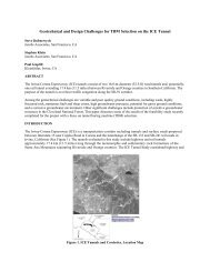
out from the <strong>Sound</strong> Transit staging site shown in Figure 1 next to Pine Street <strong>and</strong> extend at an angle below the street<br />
to prevent further surface disruption <strong>and</strong> minimize any potential traffic impacts.<br />
3