Integration of Operations and Underground Construction: Sound ...
Integration of Operations and Underground Construction: Sound ...
Integration of Operations and Underground Construction: Sound ...

You also want an ePaper? Increase the reach of your titles
YUMPU automatically turns print PDFs into web optimized ePapers that Google loves.
<strong>Integration</strong> <strong>of</strong> <strong>Operations</strong> <strong>and</strong> <strong>Underground</strong> <strong>Construction</strong>: <strong>Sound</strong> Transit University Link<br />
John Sleavin<br />
<strong>Sound</strong> Transit, Seattle, WA, USA<br />
Peter Raleigh<br />
Jacobs Associates, Seattle, WA, USA<br />
Samuel Swartz<br />
Jacobs Associates, Seattle, WA, USA<br />
Phaidra Campbell<br />
Jacobs Associates, Seattle, WA, USA<br />
ABSTRACT: Connecting an operating transit system to a new extension is always a challenge. This paper discusses<br />
the decision-making methodology <strong>and</strong> design solution <strong>of</strong> the bored tunnel connection at the Pine Street interface<br />
between the Central Link <strong>and</strong> the University Link tunnels currently being constructed for <strong>Sound</strong> Transit in Seattle,<br />
WA. The design incorporates a unique combination <strong>of</strong> ground improvement, shaft construction, <strong>and</strong> underground<br />
excavation aimed at avoiding disruption <strong>of</strong> an important arterial street <strong>and</strong> the transit operations within the<br />
Downtown Transit Tunnel. Lessons learned from Pine Street have translated into the design <strong>of</strong> the University <strong>of</strong><br />
Washington Station, where a reception shaft for tunnel boring machines (TBMs) has been incorporated within the<br />
permanent works.<br />
INTRODUCTION AND BACKGROUND<br />
As part <strong>of</strong> the Link Light Rail Project in Seattle, WA, work was completed at the Pine Street Stub Tunnel (PSST) in<br />
early 2007 for the Central Link Project. This tunnel was excavated using cut-<strong>and</strong>-cover construction within the<br />
limits <strong>of</strong> Pine Street. The stub tunnel provides both a turn back via double crossover for light rail trains running in<br />
the Downtown Transit Tunnel (DTT), as well as a connection point for the next phase <strong>of</strong> the project; the University<br />
Link.<br />
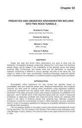
Figure 1. Conceptual site layout <strong>of</strong> the Pine St. Site showing temporary access shaft <strong>and</strong> adjacent to PSST<br />
ventilation shaft<br />
Designing the new University Link tunnel connection to the existing PSST was a tricky task. The on-site<br />
geotechnical conditions, buried obstructions, geometry, requirements for construction <strong>and</strong> balancing operational<br />
1
considerations <strong>and</strong> neighborhood stakeholder concerns associated with the recently completed PSST combined to<br />
create a uniquely challenging assignment.<br />
Site geotechnical challenges included rubble fill, l<strong>and</strong>slide deposits, <strong>and</strong> possible contamination soils. Soldier piles<br />
<strong>and</strong> tiebacks in the path <strong>of</strong> the both the Northbound (NB) <strong>and</strong> Southbound (SB) running tunnels, an electrical vault,<br />
duct bank, <strong>and</strong> a vent shaft partially above the tunnels, in addition to an existing deep sewer above the Southbound<br />
(SB) tunnel rounded out the buried obstructions we had to contend with. The geometry <strong>of</strong> the PSST connection was<br />
originally designed for a tunnel alignment towards First Hill <strong>and</strong> during the preliminary engineering design the<br />
alignment was changed to Capitol Hill. The recent history <strong>of</strong> construction in the area presented us with a further<br />
challenge <strong>of</strong> making the connection without causing disruption <strong>of</strong> traffic on Pine Street. Operational considerations<br />
within the PSST dictated limited access <strong>and</strong> work hours impacting the construction stage where complicated<br />
connections to the PSST for waterpro<strong>of</strong>ing, electrical, mechanical, temporary ventilation, <strong>and</strong> systems components<br />
needed to be made.<br />
Preliminary Engineering Design<br />
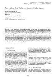
The preliminary engineering (PE) concept for the connection shown in Figure 2 below involved the excavation <strong>of</strong><br />
two tunnel boring machine (TBM) retrieval shafts (one for the SB tunnel <strong>and</strong> one for the NB tunnel), the<br />
construction <strong>of</strong> tunnels excavated using the sequential excavation method (SEM),between these shafts, <strong>and</strong> the<br />
PSST headwall. The proposed short SEM tunnels, which were between 27 <strong>and</strong> 35 m (90 <strong>and</strong> 115 ft) in length, would<br />
have included the removal <strong>of</strong> tiebacks <strong>and</strong> soldier piles that intersect the proposed tunnel alignment adjacent to the<br />
PSST headwall.<br />
Figure 2. Plan view <strong>of</strong> the preliminary engineering concept shafts <strong>and</strong> SEM works<br />
During final design, an alternative approach was developed that would fulfill the tall order <strong>of</strong>:<br />
� reducing the overall costs <strong>of</strong> the connection,<br />
� facilitating access to the existing PSST headwall<br />
� avoiding excavation <strong>of</strong> retrieval shafts in close proximity to the existing I-5 Freeway<br />
� removing the soldier piles <strong>and</strong> anchors within the tunnel envelope<br />
� preparing for TBM excavations up to the face <strong>of</strong> the PSST headwall<br />
2
� removing the heavily reinforced concrete tunnel “eyes” without undue disturbance to the ongoing<br />
transit operations<br />
ALTERNATIVE DESIGN<br />
A few alternative approaches were originally considered, in addition to the PE design. One <strong>of</strong> the initial ideas was to<br />
determine whether any <strong>of</strong> the TBM breakthrough preparation work could be carried out under the PSST contract,<br />
which was still underway at the beginning <strong>of</strong> the University Link design period. This preparation work would have<br />
consisted <strong>of</strong> the removal <strong>of</strong> the partially exposed soldier piles <strong>and</strong> part <strong>of</strong> the anchors that intersect the proposed<br />
tunnel alignment from the surface prior to the restoration <strong>of</strong> Pine Street, as well as removal <strong>of</strong> the break-out panels<br />
in the PSST headwall. However, it was quickly ascertained that this idea would be difficult to implement given the<br />
necessity for a very late change to the scope <strong>and</strong> schedule <strong>of</strong> the PSST contract, which was near completion at that<br />
time.<br />
The alternative discussed in this paper was developed as part <strong>of</strong> the Capitol Hill Tunnel contract (U230), <strong>and</strong><br />
eliminated the need for any further construction work within Pine Street, minimizing disruption to residences <strong>and</strong><br />
businesses in the area. This alternative was used in the final design, <strong>and</strong> involved the following activities:<br />
� Ground treatment to facilitate tieback removal through the TBM cutterhead for the SB tunnel, <strong>and</strong><br />
stabilizing TBM break-ins for both tunnels.<br />
� Installation <strong>of</strong> “demising wall” bulkheads within the PSST to facilitate removal <strong>of</strong> the NB <strong>and</strong> SB breakout<br />
panels <strong>and</strong> installation <strong>of</strong> utility connections <strong>and</strong> light rail within an agreed length <strong>of</strong> the PSST<br />
� Temporary access/retrieval shaft construction for the NB tunnel only, taking advantage <strong>of</strong> the PSST<br />
headwall <strong>and</strong> the existing Controlled Density Fill (CDF) backfill on two <strong>of</strong> the four shaft sides.<br />
� Access drift from the temporary shaft to a temporary chamber, constructed within the safety <strong>of</strong> the CDF<br />
located between the existing soldier pile wall <strong>and</strong> the PSST headwall.<br />
� Removal <strong>of</strong> soldier piles from the temporary chamber <strong>and</strong> replacement with CDF backfill.<br />
� In-tunnel disassembly <strong>of</strong> the SB tunnel TBM.<br />
� Removal <strong>of</strong> soldier piles from NB retrieval shaft.<br />
Figure 3 shows a general layout <strong>of</strong> the alternative used in the final design.<br />
Ground Treatment<br />
Due to the presence <strong>of</strong> both recent alluvium deposits <strong>and</strong> l<strong>and</strong>slide deposits below the groundwater <strong>and</strong> overlying<br />
the over-consolidated glacial soils, a limited ground treatment zone was determined to be required for both tunnels.<br />
The ground treatment zones, as shown in Figure 3, vary for each tunnel. For the NB tunnel, the zone is large enough<br />
to provide a stable face to allow for bottom removal <strong>of</strong> the east soldier piles, which are used for support <strong>of</strong> the<br />
retrieval shaft <strong>and</strong> later be removed from the path <strong>of</strong> the TBM. For the SB tunnel, the zone also needed to provide a<br />
stable face for the east soldier pile removal, but also provide stability for the tunnel heading to allow removal <strong>of</strong><br />
tiebacks from within the face <strong>of</strong> the TBM, to be carried out under atmospheric pressure. The SB tunnel geometry<br />
was also dictated by an existing sewer that needs to stay in operation throughout the tunnel construction phase.<br />
Ground treatment to stabilize the tunnel crown <strong>and</strong> improve the soil st<strong>and</strong>up time was designed as jet grouting<br />
because <strong>of</strong> the high silt content <strong>of</strong> the in situ soils, <strong>and</strong> used to create a consolidated block <strong>of</strong> material in the zone <strong>of</strong><br />
l<strong>and</strong>slide debris between the alluvium <strong>and</strong> over-consolidated glacial soils. This work has been planned to be carried<br />
out from the <strong>Sound</strong> Transit staging site shown in Figure 1 next to Pine Street <strong>and</strong> extend at an angle below the street<br />
to prevent further surface disruption <strong>and</strong> minimize any potential traffic impacts.<br />
3
Operational considerations <strong>and</strong> Neighborhood stakeholder concerns at the PSST<br />
Early in the design <strong>of</strong> the connection design it was made clear to us that disruption <strong>of</strong> the <strong>Sound</strong> Transit <strong>and</strong> King<br />
County Metro operations within the PSST had to be held to a minimum. After some reflection on all <strong>of</strong> the<br />
construction activity that could not be avoided within the PSST <strong>and</strong> the risks this posed to ongoing transit operations<br />
the concept <strong>of</strong> “demising walls” was developed. The “demising walls” are fixed bulkheads fitted out with roller <strong>and</strong><br />
personnel access doors constructed between 15 <strong>and</strong> 20 m (50 <strong>and</strong> 65 feet) from the PSST headwall in order to create<br />
a construction exclusion work zone. These bulkheads have been designed to prevent the communication <strong>of</strong> dust <strong>and</strong><br />
noise from the zone, control personnel access into the active transit operations area, <strong>and</strong> maintain the integrity <strong>of</strong> the<br />
existing FLS (Fire Life Safety) ventilation. Installation <strong>of</strong> the bulkheads could not avoid impacts to the PSST.<br />
Relocation <strong>of</strong> the light rail “bumper posts” reduces the available storage length for light rail vehicles by<br />
approximately 60 feet <strong>and</strong> restricts <strong>Sound</strong> Transit to two-car travel. However, the advantages <strong>of</strong> the bulkheads<br />
outweighs this temporary inconvenience to operations <strong>and</strong> <strong>Sound</strong> Transit will not need a three-car service until the<br />
completion <strong>of</strong> University Link in 2016. Once the bulkheads have been installed they will remain in place until all<br />
systems <strong>and</strong> other finishing works have been carried so that the seamless integration <strong>of</strong> the U-Link with the PSST<br />
can be completed.<br />
To address the concerns that site neighbors <strong>and</strong> other stakeholders would have <strong>of</strong> further construction being carried<br />
out that would disrupt traffic on Pine St. the design team came up with a feasible approach that would ensure that for<br />
the most part construction activities would take place within the site boundaries, only stepping outside into the side<br />
walk areas for very specific operations such as the angled jet-grouting below Pine St as shown in Figure 3.<br />
Figure 3. Jet grouting below Pine St.<br />
4
Figure 4. Plan view showing the adopted final design alternative connection (sections arrows provide some<br />
idea <strong>of</strong> the detailed engineering required to make the design work)<br />
Temporary Shaft Support<br />
<strong>Construction</strong> <strong>of</strong> the temporary access/retrieval shaft for the NB TBM tunnel has been designed to proceed according<br />
to the following steps:<br />
� A roughly rectangular shaft will be constructed so that the PSST headwall <strong>and</strong> additional temporary soldier<br />
piles will support the shaft excavation from elevation 52 m (170 ft) to the base <strong>of</strong> the PSST structure. The<br />
layout <strong>of</strong> the piles avoids the electrical duct bank <strong>and</strong> the overhang <strong>of</strong> the existing vent structure.<br />
� The 22 m (70 ft) shaft will rely on the temporary soldier piles, wales at 2.4 to 3.7 m (8 to 12 ft) level<br />
intervals, <strong>and</strong> timber lagging are anticipated, similar to the successful model used for temporary excavation<br />
support <strong>of</strong> the PSST.<br />
� Temporary soldier piles will be installed in order to safely excavate the shaft to the level <strong>of</strong> the access drift<br />
<strong>and</strong> provide access for removal <strong>of</strong> the existing soldier piles within the shaft.<br />
� Upon completion <strong>of</strong> the works for the temporary pile removal chamber, the shaft will be excavated to a<br />
point where the NB tunnel headwall break-out panel can be removed.<br />
� Existing soldier piles that were used as temporary support for the PSST <strong>and</strong> are within the Temporary<br />
Access Shaft will be removed.<br />
� Once this work has been completed, all the soldier piles within the tunnel envelope will be cut or extracted<br />
after bracing the existing piles in lifts, with removal carried up to 0.6 m (2 ft) above the crown.<br />
5
� The shaft will then be partially backfilled in lifts corresponding to the pile removal sequence above, with<br />
CDF material to allow for the NB tunnel TBM to mine into the shaft.<br />
Figure 5 shows an isometric view <strong>of</strong> the shaft.<br />
Figure 5. View <strong>of</strong> shaft showing existing <strong>and</strong> additional support elements<br />
Access Drift <strong>and</strong> Pile Removal Chamber<br />
In order to avoid surface disruption to Pine Street a 3 × 3 m (10 × 10 ft) access has been designed to be driven from<br />
the shaft above tunnel axis level within the CDF material between the NB <strong>and</strong> SB tunnels. This access drift will take<br />
advantage <strong>of</strong> the existing PSST soldier piles on the east side for support. The drift excavation <strong>and</strong> chamber top<br />
bench will be supported by partial steel sets, with lagging or shotcrete to ensure ground stability, placed in line with<br />
the existing piles. At this stage it will be possible for the upper part <strong>of</strong> the SB tunnel break-out panel to be exposed<br />
<strong>and</strong> removal <strong>of</strong> the concrete will begin. Subsequent benches will be excavated from the top down, exposing the<br />
entire break-out panel for removal <strong>and</strong> the complete length <strong>of</strong> piles <strong>and</strong> laggings to be removed from the tunnel<br />
envelope.<br />
Beginning from the bottom bench, laggings, piles, <strong>and</strong> 0.9 to 1.2 m (3 to 4 ft) <strong>of</strong> existing tieback will be removed<br />
after stabilizing the soldier piles. The lower portions <strong>of</strong> the pile removal chamber are expected to be in the overconsolidated<br />
Qpgm <strong>and</strong> Qpgl materials, which are stiff to very stiff clays. The upper portion <strong>of</strong> the chamber will be<br />
within the zone <strong>of</strong> ground treated soils, which should not become unstable during the short period that they are left<br />
unsupported. Figure 6 illustrates a section through the fully developed access drift <strong>and</strong> pile removal chamber which<br />
is larger than required to accommodate the tunnel envelope (SB tunnel pr<strong>of</strong>ile shown) because <strong>of</strong> the presence <strong>of</strong><br />
tieback anchor points that connect with tiebacks intersecting the tunnel horizon, as well as to allow waterpro<strong>of</strong>ing,<br />
mechanical, electrical, <strong>and</strong> systems connections to the existing PSST structure. To facilitate TBM excavation, the<br />
tiebacks will be disconnected from their associated piles within the pile removal chamber.<br />
6
Figure 6: Transverse section showing access drift <strong>and</strong> SB pile removal chamber<br />
Tieback Removal through the TBM<br />
During construction <strong>of</strong> the PSST headwall structure, the temporary excavation support soldier pile wall running<br />
northwest was supported by a tieback anchoring system. The tieback system was arranged in five rows at intervals<br />
<strong>of</strong> 3.4 to 3.7 m (10 to 12 ft), which intersect the proposed SB tunnel envelope as shown in Figure 6. The tiebacks<br />
consist <strong>of</strong> steel cables anchored over a minimum 4.6 m (15 ft) length at the cable terminus, <strong>and</strong> intersect the SB<br />
tunnels to varying degrees. The TBM is likely to encounter tiebacks over a 13.7 m (45 ft) long interval, starting<br />
approximately 16.8 m (55 ft) before the PSST headwall. In accordance with the specification an earth pressure<br />
balance (EPB) TBM will excavate in closed mode (pressurized face) up to this position <strong>and</strong> then convert to open<br />
mode (non-pressurized face) while excavating under the cover <strong>of</strong> the jet-grouted tieback zone. Following each <strong>of</strong> the<br />
7 to 8 ring excavation sequences required to mine through the tieback zone, interventions are to be carried out as<br />
necessary to cut the cables engaged by the cutterhead or exposed in the face. This is anticipated to ensure that at no<br />
time there will be more than 1.5 m (5 ft) <strong>of</strong> cable exposed which could become entangled in the TBM cutterhead.<br />
Stability <strong>of</strong> the crown during these interventions will be provided by the ground treatment zone. Figure 7 shows a<br />
perspective view <strong>of</strong> the intersection <strong>of</strong> tiebacks with the SB tunnel envelope.<br />
Figure 7: Perspective <strong>of</strong> tiebacks intersecting the SB tunnel envelope (ground treatment not shown for clarity)<br />
7
TBM Drives from I-5 to PSST<br />
Once the temporary excavation supports have been removed from the tunnel envelope, both NB <strong>and</strong> SB tunnel<br />
TBMs should be able to proceed up to the PSST headwall without difficulty. The NB TBM will be driven up to the<br />
PSST headwall <strong>and</strong> removed via the temporary access shaft. The cutterhead <strong>and</strong> shield components will be hoisted<br />
out <strong>of</strong> the shaft <strong>and</strong> loaded onto a flatbed trailer in easily transportable pieces, to be reassembled at the Capital Hill<br />
Station for the SB tunnel drive.<br />
The SB TBM will pass through the anchors (as described above) <strong>and</strong> then through the CDF, aligning roughly<br />
perpendicular with the PSST headwall. Once the SB TBM shield is in position it will be grouted <strong>and</strong> the internal<br />
elements disassembled, leaving the shield carcass as temporary support for the tunnel. The gap created following<br />
removal <strong>of</strong> the cutterhead between the shield <strong>and</strong> the PSST headwall will be temporarily supported by bracing<br />
around the shield in order to ensure ground stability. The shield diaphragms will be removed, <strong>and</strong> waterpro<strong>of</strong>ing,<br />
rebar, <strong>and</strong> concrete or shotcrete will be used to complete the circular cross section <strong>of</strong> the tunnel up to the PSST<br />
headwall. Connections for mechanical, electrical, <strong>and</strong> systems components will be made prior to placing the final<br />
lining.<br />
Final Lining <strong>and</strong> Connections<br />
After completion <strong>of</strong> the tunnel drives, the temporary shaft will be left open to allow subsequent contractors to<br />
transport materials to tunnel level without requiring access from the existing PSST. As a final step, a cast-in-place<br />
concrete lining will be installed to bridge the gap between the precast concrete segmental lining installed in the<br />
tunnel <strong>and</strong> the PSST headwall, including connections for waterpro<strong>of</strong>ing, mechanical, electrical, <strong>and</strong> systems<br />
components. The shaft will then be backfilled to the ground surface <strong>and</strong> the existing site restored.<br />
Lesson learned: Design <strong>of</strong> the Northlink connection interface<br />
As illustrated above the conditions in <strong>and</strong> around the PSST were less than ideal for reception <strong>of</strong> the TBMs <strong>and</strong><br />
considerable design was required to address the unique challenges <strong>of</strong> the site. As part <strong>of</strong> the University link both<br />
<strong>Sound</strong> Transit <strong>and</strong> their designer wanted to “think ahead” <strong>and</strong> avoid the difficulties encountered in designing the<br />
Pine Street connection. To address this issue, the north end <strong>of</strong> the University <strong>of</strong> Washington station (UWS) has been<br />
designed to incorporate a reception area <strong>and</strong> shaft for TBM removal. A number <strong>of</strong> design elements were<br />
incorporated into the north end <strong>of</strong> UWS to ease future construction. These elements include:<br />
� Access rights have been worked out with the University <strong>of</strong> Washington to allow for the removal <strong>of</strong> TBMs<br />
from the north end <strong>of</strong> UWS.<br />
� A TBM retrieval shaft has been built into the permanent works <strong>of</strong> the north end <strong>of</strong> the UWS, to allow<br />
removal <strong>of</strong> the TBMs as they mine into the station.<br />
� Fiberglass reinforcing bars have been incorporated into the final design <strong>of</strong> the headwall at the north end <strong>of</strong><br />
the UWS, to allow easier removal <strong>of</strong> the concrete headwall for the TBM break-ins.<br />
� A block <strong>of</strong> treated ground will be created at the break-in points to the shaft headwall.<br />
� The north headwall was designed to be perpendicular to the direction <strong>of</strong> the anticipated TBM drives.<br />
Conclusions<br />
The design <strong>of</strong> the connection <strong>of</strong> the University Link tunnels to the existing infrastructure at the Pine Street Stub<br />
Tunnel (PSST) presented many challenges. Preliminary engineering (PE) concepts anticipated retrieval shafts <strong>and</strong><br />
short tunnels excavated using Sequential Excavation Methods (SEM) for this connection, as shown in Figure 2.<br />
However, limited access within the existing PSST structure for the SEM tunnels required an alternative approach.<br />
Use <strong>of</strong> a retrieval shaft adjacent to the existing box structure was designed to accommodate the Northbound Tunnel,<br />
<strong>and</strong> a short access drift to the Southbound Tunnel will allow construction to be performed with only limited impact<br />
on operations within the existing PSST structure via the use <strong>of</strong> a demising wall. This method also limits impacts to<br />
8
adjacent Pine Street; eliminates SEM works; allows tunneling to be performed by TBM for the entire tunnel<br />
alignment which has both schedule <strong>and</strong> cost advantages; ensures safety <strong>and</strong> security in the PSST; minimizes<br />
interference with existing or ongoing transit operations to reduce risks from both safety <strong>and</strong> contractual points <strong>of</strong><br />
view; reduces schedule risk by performing preparatory works at PSST prior to the arrival <strong>of</strong> the TBMs; <strong>and</strong> gives<br />
some additional flexibility for making connections to the existing structure for waterpro<strong>of</strong>ing, as well mechanical,<br />
electrical, ventilation, <strong>and</strong> systems components.<br />
Finally, the lessons learned from the PSST connection have been directly put to use at the north end <strong>of</strong> the U-Link<br />
project where UWS ties in with the future running tunnels expansion to the North. Future running tunnels coming<br />
into the station will be provided with a TBM retrieval shaft built into the permanent works <strong>of</strong> the station, greatly<br />
reducing the impact <strong>of</strong> the future expansion on the operations <strong>of</strong> the University Link light rail.<br />
9