A-102-1 Electric Duct Heater Brochure - Brasch
A-102-1 Electric Duct Heater Brochure - Brasch
A-102-1 Electric Duct Heater Brochure - Brasch
- No tags were found...

You also want an ePaper? Increase the reach of your titles
YUMPU automatically turns print PDFs into web optimized ePapers that Google loves.
Bulletin A<strong>102</strong>-1© <strong>Brasch</strong> Manufacturing Co., Inc.
IndexBottom Insert . . . . . . . . . . . . . . . . . . . . 11Raintight Construction . . . . . . . . . . . . . . 11Bottom Outlet . . . . . . . . . . . . . . . . . . . . 12Recessed Terminal Box. . . . . . . . . . . . . . 10Construction Details . . . . . . . . . . . . . . . 6, 7Round-<strong>Duct</strong> Construction . . . . . . . . . . . . 14Dusttight <strong>Heater</strong>s. . . . . . . . . . . . . . . . . . 10SCRs . . . . . . . . . . . . . . . . . . . . . . . . . . . 8Express <strong>Duct</strong> <strong>Heater</strong>s . . . . . . . . . . . . . . . 27SCR-Vernier . . . . . . . . . . . . . . . . . . . . . . 8Finned Tubular Construction . . . . . . . . . . 15Single Zone. . . . . . . . . . . . . . . . . . . . . . 16Flanged Construction . . . . . . . . . . . . . . . . 5Sizes and KW Ratings . . . . . . . . . . . . . . . 3Installation . . . . . . . . . . . . . . . . . . . . . . . 5Slip-in Construction . . . . . . . . . . . . . . . . . 5Insulated Terminal Box . . . . . . . . . . . . . . 12Specification, Sample. . . . . . . . . . . . . . . . 4Multizone . . . . . . . . . . . . . . . . . . . . . . . 16Step Controllers. . . . . . . . . . . . . . . . . . . . 8NEC Requirements . . . . . . . . . . . . . . 24-26Technical Data. . . . . . . . . . . . . . . . . . . . 16Oven <strong>Heater</strong>s . . . . . . . . . . . . . . . . . . . . 13Thermostats . . . . . . . . . . . . . . . . . . . . . . 9Pressure Drop Graph . . . . . . . . . . . . . . . 18Wiring Diagrams-Control Systems. . . . 20-23Protective Screens . . . . . . . . . . . . . . . . . 13UL . . . . . . . . . . . . . . . . . . . . . . . . . . . . . 3Quality Control. . . . . . . . . . . . . . . . . . . . . 32 BRASCH MANUFACTURING
Ratingsand SizesYou specify it—we build it! <strong>Heater</strong>sdescribed in this bulletin are customdesigned at no extra charge to yourexact size, wattage, voltage andphase and number of steps. Any ductsize from W = 5" and H = 4" minimumto W = 480" and H = 180"maximum, wattages to 2000 KW canbe furnished. Base price dependsupon duct size and KW rating; baseprice is the same for single or threephase and does not change withnumber of steps.For practical design of heater, minimumrecommended KW per step is .5KW for 208V single phase; 1.0 KW for277V or 480V single phase and 2.0KW for 480V or 600V three phase.UL ListingUL Listed by Underwriters Laboratories, Inc. under File Nos. E 39836 and E39386for zero clearance between heater and combustible surfaces. Listing includes allbuilt-in components unless otherwise noted. <strong>Heater</strong>s are also UL Listed for usewith heat pumps and air conditioners when mounted 4 feet or more from unit andmaximum inlet air temperature is 100°F.Quality Control<strong>Heater</strong>s are dielectrically tested for 1000V plus twice the rated voltage or 2000V,whichever is higher. The resistance of each heater is measured and recorded andmust be within 5% of rated value. <strong>Electric</strong>al components are tested and inspectedafter installation in the heater. Every heater is checked twice; once in productionand once by a trained Quality Control inspector who gives each heater a thoroughinspection.Suggested Schedule for <strong>Electric</strong> Heating CoilsHorizontalInsideor<strong>Duct</strong> Type VerticalTag Size CFM No. of Control of AirflowNO. W' x H' (Min.) KW Voltage/Phase Steps Volts Control Direction Special FeaturesEH-1 to 10 12 x 8 430 5.0 480/3 2 24 PE Direct ActingEH-11 18 x 12 750 21.5 480/3 1 24 SCR HAF Direct Acting TransducerAH-1 — 5000 85.0 480/3 6 24 Step Control Preheat for Carrier 39BA120-BBULLETIN A<strong>102</strong>-13
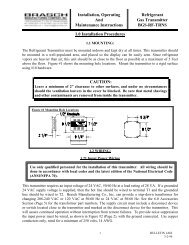
TypesFigure 2A Flanged <strong>Heater</strong>Figure 1A Slip-in <strong>Heater</strong>SLIP-IN HEATER—standard and by far the most widely used becauseof the ease of installation; see 1A and 1B. When built-in controls arespecified in a slip-in heater, they are usually mounted in the left-handoverhang (S dimension in Figure 1B). If right-hand overhang is desired,specify S dimension to be 1", T dimension as required.FLANGED HEATER—(optional) consists of a slip-in heater mounted in aflanged duct section; see Figures 2A and 2B. The slip-in portion slides outwithout removing flanges from duct. When built-in controls are specified ina flanged heater, they are mounted in the terminal box of the slip-in portion;the frame containing the elements stays the same. The flanged duct sectionis increased in depth to accommodate the larger terminal box.DimensionsFigure 1BFigure 2BH = 4" minimum, 180" maximum; W = 5" minimum, 480" maximum (for sizes over H = 90" or W = 120", consult factory). E, F, S, T, Y and G dimensionsdepend on KW, voltage, phase, number of steps and built-in controls; consult factory.InstallationBulletin I-17 or I-556-1 is included with each heater. Covers maintenance and installation warnings on how NOT to install duct heaters. Service instructions also given.Figure 1CFigure 2CFigure 1C SLIP-IN HEATERStep 1. Cut hole in side of duct 1/8" larger than heater body.Step 2. Insert heater until terminal box covers opening.Step 3. Secure heater in place with sheet metal screws.BULLETIN A<strong>102</strong>-1Figure 2C FLANGED HEATERStep 1. Provide flanges on ends of duct matching heater flangesStep 2. Secure heater flanges to duct flanges with sheet metal screws,so that mounting screws do not enter terminal box.5
Construction DetailsAutomatic reset thermal cutout (primarysafety protection) standard on everyheater. Automatically resets after heaterhas cooled. Wired in series with elementson single phase heaters notexceeding the ratings. For all otherheaters cutout controls contactors.Manual reset thermal cutout(optional) secondary safety protection.External reset button isnormally located in terminalbox cover.NOTE:Central location of thermal cutout allows sameheater to be used for left- or right-hand and verticalup airflow.Main supply terminals for connectionto copper supply wires(standard).Ground lugBuilt-in transformer providescontrol voltage ifnot same as line voltage.(Optional)Properly sizedknockoutsControl terminalsReset button for manualreset thermal cutout.(Optional)Built-in fuses.(Optional)Built-in magnetic contactor.(Optional)Heavy gauge corrosion protected terminalbox (galvanized steel standard)Terminal box cover is solid, nonperforated type,assuring dust-free, trouble-free operation ofbuilt-in contactors. Screws are accessible fromfront. Hinged cover provided when fuses, PEswitches, or interlocking disconnect switch arebuilt-in. (Cover shown separate here for clarity)Figure 1Typical Slip-in <strong>Heater</strong> (Featuresalso apply to flanged heaters)6 BRASCH MANUFACTURING
Open coil iron-free heating elements. Highest grade (80%nickel, 20% chromium) Type A resistance wire has longer life;coils do not sag or oxidize; resistance does not change withtime; glowing is minimized with sufficient airflow. Elementsare spread across the face of the heater, when practical, toavoid stratification.Optional finned tubular heating elements.80/20 nickel/chromium innercoil centered in copper-plated steeltubes; magnesium oxide filler assuresrapid heat transfer from coil to steelfins brazed to tube; silicone rubberdouble seals prevent magnesium oxidecontamination. High temperature aluminumcoating protects element surfacesfrom corrosion.Secondary disc-type cutouts standard on every heater. Set athigher temperature than automatic reset thermal cutout. MeetsUL and NEC requirements. Sufficient number of cutouts locatedin the power lines de-energize elements should automatic resetthermal cutout fail; easily serviced through the terminal box. Noback-up contactors are required.Support brackets with special reinforcements(ribbing along edges and gussetsin top and bottom mounting flanges)BULLETIN A<strong>102</strong>-1Coil terminations have been designedto assure trouble-free connections.Ceramic bushings and stainless steelterminals guard against high temperatures.Coil connection is machinecrimped and nuts are tightened tospecified torque.7
Step ControllersStep controllers are used to control multi-step heaters.ELECTRONIC MODULATINGSolid state electronic step controllers will switch up to tencontactor holding coils each and may be wired in series fora maximum of 30 steps. They are available with a singleinput from all commonly used thermostat input signals.The step controller automatically recycles to the full-offposition in case of a power interruption.SCRsSCR VernierSilicone controlled rectifiers (SCRs) are used to provide very close heat controland/or silent operation for critical areas such as laboratories, computer rooms andexecutive offices. They are a solid state device with no moving parts which willprovide 100% stepless and noiseless modulation through many years of troublefree service. The SCR has heat sink mounted protruding through the terminal boxto maximize convection cooling. The heat sink is electrically insulated from liveparts. Power and heat output are precisely controlled from zero to 100% in directresponse to the modulating thermostat signal (figure 25). All commonly used thermostatinput signals will be accepted by the SCR without a special interface. Asafety contactor must be used.SCR Vernier systems are used on larger KW heaters where very close heat controlis required. The SCR Vernier system employs a combination of SCR and non-SCR steps. For electric/electronic controls, a step controller energizes the non-SCR steps; for pneumatic controls, adjustable differential PE switches energizethe non-SCR steps. The system is more economical for larger KW heaters thanfull SCR control while providing the same very close heat control as the full SCRsystem. This is accomplished by satisfying most of the heat requirement throughthe non-SCR steps and then the last portion of the heat requirement is "finetuned"by the modulating SCR controller. The SCR step is nominally equal to theKW of a non-SCR step to provide an even transition between steps.All elements in the heater are simultaneously controlled, thus avoiding problemsof air stratification. Zero angle firing interrupts the full wave AC cycle only whencurrent passes through zero, minimizing radio frequency interference.8 BRASCH MANUFACTURING
ThermostatsTable 23: ThermostatsCatalogNumber Type Temp. Range Ratings Action No. StepsT-101 Room 40 - 90° F 120 - 240V Pilot 1T-<strong>102</strong> Room 40 - 90° F 120 - 240V Pilot 2T-111 Room 40 - 90° F 24V Pilot 1T-112 Room 40 - 90° F 24V Pilot 2T-201 Room 40 - 90° F 120 - 277V Line 1T-300 Room 60 - 90° F D.C./Resistive Output Step Controller Mod.C<strong>102</strong>5 Room 60 - 90° F D.C./Resistive Output SCR Mod.T-400 Room 40 - 90° F Pneumatic Direct Acting Mod.T-401 Room 40 -90° F Pneumatic Reverse Acting Mod.T-601 <strong>Duct</strong> 60 -90° F 120 - 240V Pilot 1T-602 <strong>Duct</strong> 60 - 90° F 24 - 240V Pilot 2T-603 <strong>Duct</strong> 60 - 90° F 24 - 277V Pilot 3T-604 <strong>Duct</strong> 60 - 90° F 120 - 277V Pilot 4T-810 <strong>Duct</strong> 80 - 100°F D.C./Resistive Output Step Controller Mod.T-100-M043 <strong>Duct</strong> 0 - 180°F D.C./Resistive Output SCR Mod.TG-100M Thermostat Guard — — — —NOTE: Data subject to change without notice.BULLETIN A<strong>102</strong>-19
Special Constructions<strong>Heater</strong>s for<strong>Duct</strong>s withInternalObstructionsRECESSED TERMINAL BOX—forslip-in heaters; brings element terminalsand thermal cutouts further intothe airstream (recommended wherethe element terminals are blocked byan obstruction of more than 1").DUSTTIGHT TERMINAL BOX—slip-in orflanged heaters have sturdy terminal box andcover with sealed seams. A gasket is providedinside the terminal box cover to seal the cover tothe terminal box. UL Listed for indoor use only.10 BRASCH MANUFACTURING
Bottom TerminalBoxesBOTTOM INSERT—slip-in heater inserts througha hole in the bottom of a horizontal duct. Internalterminal box contains resistance coil terminations,automatic reset and secondary thermal cutouts, allprewired to terminal blocks in field terminal box.Control components such as contractors, fusesand transformers are mounted in bottom terminalbox. Specify W and H dimensions (minimum Wdimension is 12").RAINTIGHT HEATER—UL Listed for outdooruse; formed of heavy gauge galvanized steel,sealed with high temperature sealant. May besupplied with recessed construction. Flangedconstruction fits any horizontal, rectangular duct.Available with standard built-in components thatdo not protrude through door such as contactors,fuses, transformers, step controller, PE switches,etc. Insulated terminal box or insulated flange arenot available UL Listed. Consult local representativefor additional information. Not suitable for usein salt spray environments.BULLETIN A<strong>102</strong>-111
Special Constructions (cont.)BOTTOM OUTLET—recommended wherea flanged heater is desired with field terminalbox at the bottom of the horizontal duct.Internal terminal box contains resistancecoil terminations, automatic reset thermalcutout and secondary thermal cutouts, allprewired to terminal blocks in field terminalbox. Control components such as contactors,fuses and transformers are mountedin bottom terminal box. Not available withbuilt-in weather resistant or dusttight terminalbox.INSULATED TERMINAL BOX—recommendedwhenever heaters are used in airconditioning ducts in areas with high relativehumidity. Slip-in or flanged heaters withinsulated terminal box have insulatingboard fastened to the back of the terminalbox, between the duct and the terminal box.12 BRASCH MANUFACTURING
PROTECTIVE SCREENS—prevent accidentalcontact and possible electrical shock,especially where maintenance personnel arelikely to enter the duct near the heater.Galvanized 1/2" x 1/2" hardware cloth meshis standard. Screen also prevents debris suchas loose duct insulation, etc. from contactingheater coils.When ordering, specify:A. Inlet Side OnlyB. Outlet Side OnlyC. Both SidesOVEN HEATER—designed for heating, dryingand baking applications in industrial ovens. Airtemperatures to 1200° F are maintained byforced air circulation. Highest Grade Type A(80/20) resistance wire elements minimize oxidation.Elements are derated on an increasing scaleto match design temperature conditions. Framesare of galvanized, aluminized, or stainless steel,depending on outlet temperature. Optional featuresinclude control thermostat, high limit cutout,airflow switch, remote panel with built-in components.UL or not UL Listed.BULLETIN A<strong>102</strong>-113
Finned TubularSLIP-IN AND FLANGED—UL Listed,heavy gauge galvanized steel frame(aluminized and stainless optional); solidcover; nonperforated terminal box (dusttightNEMA 12 optional); properly sizedknockouts; interchangeable airflow, horizontalin either direction or vertical up.Finned elements use 80/20nickel/chromium resistance wire, helicallywound and centered in a copperplated steel tube filled and compactedwith magnesium oxide for rapid heattransfer; silicone rubber double sealsprevent contamination. High temperaturealuminum coating further protectselement from corrosion. Also available infrit (glass-ceramic) coated.FLANGED HEATER (Non-Removable<strong>Heater</strong> Section)—UL Listed unitsare designed for horizontal or verticalrectangular ducts. Units are of heavygauge galvanized steel (standard) oraluminized steel (optional). Terminalbox for control components is builtin.For flanged heater with removableheater section see page 5.BULLETIN A<strong>102</strong>-115
Technical DataMULTIZONE APPLICATIONS—where electric heaters are installed in airhandling equipment with multizone dampers which constantly reposition,depending on the requirements of each zone, special precautions must betaken in the design of the heaters.Both slip-in and flanged heaters are suitable for multizone equipment,depending upon the configuration of the unit. The frame dimensions mustbe carefully chosen so the heater will fit the multizone unit. We recommendthe dimensions be approved by the multizone unit manufacturer.Care must be taken so that no part of the heater face area is blocked bythe frame members, cooling coil headers, filter supports or blower housings.Multizone heaters should be ordered with no coils three to four inchesfrom the top, bottom or back flanges because these areas are exposedto reduced airflow conditions. If necessary, a recessed terminal box canbe used to extend element terminals into the airstream, past any obstructions.Multizone heaters must be significantly derated in terms of wattdensity per square inch of heating element surface; 25 watts maximumper square inch of element is recommended.A special linear cutout must be ordered in addition to standard primaryand secondary thermal cutouts. The linear cutout deenergizes the entireheater in the event of a temporary high temperature condition along any12" section. It will automatically reset itself and the heater will resumenormal function when the hot spot has cooled.steps is equal to at least the number of zones plus one. for larger loads, acombination step controller/SCR Vernier system is recommended. Thissystem combines the advantage of almost infinite modulation offered bySCRs with the economy of the step controller. Combination stepcontrol/SCR Vernier systems are described in detail on page 8.SINGLE ZONE AIR HANDLING UNITS—electric heaters can be used inplace of hot water or steam coils in air handling units. Slip-in or flangedconstruction can be used, depending upon which is most suitable for theparticular application. If a flanged heater is desired, but the maximumthickness of the heater is limited, a modified flange design can be used.<strong>Heater</strong> dimensions and construction should be carefully coordinated withthe air handling unit manufacturer. Follow these guidelines:1. Because airflow is not always uniform in an air handling unit, the wattdensity of the resistance wire should be reduced to a maximum of 35watts per square inch of wire surface.2. If face and bypass damper are used, watt density should be reducedto a maximum of 25 watts per square inch of wire surface. <strong>Heater</strong>must be interlocked with the face damper to prevent operation untildamper is open.Built-in components are not recommended for multi-zone applications.Instead, a remote control panel is recommended.HOT DECK CONTROL SYSTEMS—in addition to derating the coils andproviding the heater with a linear type cutout, an averaging-type thermostatextending the entire length of the hot deck is necessary to modulatethe amount of heat supplied in accordance with the actual total loadrequirement. For smaller loads, SCRs are recommended to control theentire heater, or a step controller can be used, as long as the number of3. If the face area directly adjacent to the terminal box will be blocked bya cooling coil header, baffles or frame members, a recessed terminalbox is recommended. Amount of recess must be sufficient to clearobstructions.4. All heaters for us with air handling equipment should be ordered withno heating elements three to four inches from the top, bottom andback flange. These areas often receive little or no airflow.16 BRASCH MANUFACTURING
Use these formulae as rough guidelines for estimating purposes only:Formula #1Formula #2KW* =CFM X ▲T3160▲T =KW X 3160CFM*Approximate - formulas are based on 70° F entering air and actual KWs will vary with a change of inlet temperature.TOTAL KW REQUIRED—use Formula #1 to figure total KW needed whenair volume and temperature (▲T) are known:NUMBER OF STEPS—for the average installation it is customary to figurethe temperature rise (▲T) provided by each heating step as follows:Using Formula #1, figure KW per step when temperature rise and CFM areknown. When the KW per step is known, use Formula #2 as a rule ofthumb to figure the temperature rise per step.For economy, we recommend each step be limited to a maximum of 48amperes. See page 11 for KW ratings equivalent to 48 amperes.COMFORT HEAT CONTROL DESIREDVery Fine ControlAverage ControlCoarse Control▲ T PER STEP5° or less6 to 14° F15° F and upFor practical design of heater, minimum recommended KW per step is .5KW for 208V single phase; 1.0 KW for 277V or 480V single phase and2.0 KW for 480V or 600V three phase.Minimum number of steps for multizone heaters should be equal to numberof zones plus one.BULLETIN A<strong>102</strong>-117
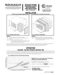
1300Minimum Air VelocityOpen Coil Elements1300Minimum Air VelocityFinned Tubular Elements*MINIMUM AIR VELOCITY (fpm)12001100100090080070060050082° - 100°F INLET AIR TEMPERATURE(HEAT PUMP APPLICATIONS ONLY)81°F MAXIMUM INLET AIR TEMPERATURE**MINIMUM AIR VELOCITY (fpm)120011001000900800700600500100°F-82°INLET AIR TEMPERATURE81°F(HEA PUMP APPLICATIONS ONLY)MAXIMUM INLET AIR TEMPERATURE*400400300300200200100———— UL100———— UL02 4 6 8 10 12 14 16 18 20 22 24 26 28 302 4 6 8 10 12 14 16 18 20 22 24 26 28 30HEATER FACE AREA (KW/FT 2 )HEATER FACE AREA (KW/FT 2 )*Maximum allowed watt density: 28.9 KW/FT 2 ) *Maximum allowed watt density: 17.0 KW/FT 2 )Face Area =KW/Ft 2 =.35(H-2 1 /2") (W- 3 /4")144KWFace Area0Example:25 KW UL <strong>Heater</strong>, Inlet 75° F12" H x 24" W, Open Coil ElementsFace Area = (12-21 /2") (24- 3 /4") = 1.53 Ft214425KW/Ft 2 == 16.31.5316.3 KW/Ft 2 = 700 fpmPressure Drop Through <strong>Heater</strong> (inches water)*PRESSURE DROP (inches water).30.25.20.15.10FINNED TUBULAR -5 COLUMNSOPEN COIL - 8" DEPTH OF COIL.050 500 1000 1500 2000VELOCITY (fpm)*This is an estimate ony and will vary with the specific construction of each heater. Calculations for specific heaters can be run on a computer program but are still rough approximatoions. Actual pressure drops can only be found by performingpressure drop tests on the actual duct heater after manufacture.18 BRASCH MANUFACTURING
How to Calculate Line CurrentsTo determine the line current use the following formulaeSingle PhaseLINE CURRENT (I L ) in amperes =WATTAGEVOLTAGE1øVoltage{(I L ) Line CurrentThree PhaseLINE CURRENT (I L ) in amperes =WATTAGEVOLTAGE X 1.73NOTE: This is the current which will flow in each of the three lines, regardless of whether the elements are wye or delta connected.(I L ){ {Voltage Delta3ø3øVoltage(I L )WyeSUPPLY WIRE AND LINE TERMINALS SIZING—UL requires thatthe line terminals in duct heaters be sized to accept conductorswhich are rated to carry at least 125% of heater line current. <strong>Heater</strong>sare provided with properly sized terminals at no extra charge. Fieldsupply wires must be sized to carry at least 125% of heater line currentexcept when the heater is for space heating, is over 50KW andnot more than 3 wires in the conduit—may be sized at 100% ofheater line current.Supply conductors must have insulation rated atleast 75° C (167° F).BULLETIN A<strong>102</strong>-119
Wiring Diagram Control System 1Single or multi-step heater with de-energizing magnetic contactors per step, fusing per NEC and 24 volt transformer. Can be controlled by a single/multiplestage room or duct thermostat, remote step controller and modulating room or duct thermostat or signal from various electronic building systemcontrols. Standard options available include disconnecting magnetic contactors, interlocking disconnect switch and remote control panel. For otheroptions, consult factory or the local <strong>Brasch</strong> representative.20 BRASCH MANUFACTURING
Wiring Diagram Control System 2Multi-step heater with de-energizing magnetic contactors per step, built-in step controller, fusing per NEC and 120 bolt transformer with primary fusing. Canbe controlled by a modulating room or duct thermostat or signal from various electronic building system controls. Standard options available include disconnectingmagnetic contactors, interlocking disconnect switch and remote control panel. For other options, consult factory or the local <strong>Brasch</strong> representative.BULLETIN A<strong>102</strong>-121
Wiring Diagram Control System 3Multi-step heater with SCR Vernier control. Step 1 is SCR and is equal to each step on the step controller. Controls include SCR's, step controller, deenergizingmagnetic operating contactors per step and safety contactor, fuses per NEC, and 120 bolt transformer with primary fusing. Can be controlledby a modulating room or duct thermostat or signal from various electronic building system controls. Standard options available include disconnectingmagnetic contactors, interlocking disconnect switch and remote control panel. For other options, consult factory or the local <strong>Brasch</strong> representative22BRASCH MANUFACTURING
Wiring Diagram Control System 4Total SCR controlled heater with SCR's, de-energizing magnetic safety contactors per step and safety contactor, fuses per NEC, and 24 volt transformer.(Above approximately 100 amps total heater load, the economics of System 3 should be considered). Can be controlled by a modulating room or ductthermostat or signal from various electronic building system controls. Standard options available include disconnecting magnetic contactos, interlockingdisconnect switch and remote control panel. For other options, consult factory or the local <strong>Brasch</strong> representative.BRASCH BULLETIN MANUFACTURING A<strong>102</strong>-1 BULLETIN23
UL/NEC Requirements*REQUIREMENTDOUBLE SAFETY PROTECTIONUL 1996, Paragraph 23.3.1:"A duct heater shall be equipped with one or more automatically resetting temperaturelimitingcontrols, as determined by 23.3.3, that will disconnect the heating element or elementsfrom the supply circuit to prevent temperatures from exceeding the limits specified.These temperature-limiting controls shall be factory-installed as an integral part of theheater."NEC Article 424-64:"Limit Controls. Each duct heater shall be provided with an approved, integral, automaticresettemperature-limiting control or controllers to de-energize the circuit or circuits."Secondary ControlNEC Article 424-64 (continued):"In addition, an integral independent supplementary control or controllers shall be providedin each duct heater that will disconnect a sufficient number of conductors to interruptcurrent flow. This device shall be manually resettable or replaceable."UL 1996, Paragraph 23.3.9:A duct heater shall be provided with one or more manually resettable or replaceable backupprotective devices of the type specified in 23.3.7, that will, with the contacts of theautomatically reset limit control permanently closed, limit the temperature to comply withthe requirements specified in the Back-up Protection Tests, Section 33.Paragraph 23.3.10:The manually resettable or replaceable protective devices specified in 23.3.9 shall befunctionally independent of the automatically reset limit control. The following types ofcontrols comply with this requirement:A. On or more thermal cutoffs, nonresettable limit controls, or manually resettable limitcontrols connected to open a sufficient number of ungrounded conductors to permitthe unit to comply with the specified temperture limits.B. A combination consisting of one or more normally open magnetic contactors andthermal cutoffs, nonresettable limit controls, or manually resettable limit controls. Thethermal cutoff or limit control shall be connected in the coil circuit of the contactor.The combination shall be intergral witht he product; be able to open a sufficient numberof ungrounded supply conductors to permit the product to comply with the specifiedtemperature limits; and be independent of control by an automatic cycling devicewith the unit.CONTROLLERS AND DISCONNECTING MEANSNEC article 424-20:(a) Serving as Both Controllers and Disconnecting Means. Thermostatically controlledswitching devices and combination thermostats and manually controlled switchesshall be permitted to serve as both controllers and disconnecting means provided all ofthe following conditions are met:HOW BRASCH MEETS REQUIREMENTEvery heater is furnished with an automatic reset thermal cutout of the bimetallic disc typeThis device is sol located that the airflow through the heater can be either left- or righthandor vertical up and the device is serviceable without having to remove heater fromduct. On larger heaters, where UL requires additional thermal cutouts, these are providedat no extra charge.<strong>Brasch</strong> heaters have always had double safety protection as standard and without additionalcharge. To meet the requirement for a manually replaceable cutoff, a sufficient numberof secondary cutouts are provided in every heater. Secondary cutouts are:1. Factory prewired in the power lines of the heating elements and are not dependentupon back-up contactors or other devices in the control circuit which may fail to open.2. Spread throughout the terminal box to give protection to the particular elements whichthey serve. Thus they will sense unsafe conditions even if they occur in th lower portionof the heater.3. Easily replaced with locally stocked factory replacements once the unsafe conditionhas been corrected. Unlike the manual reset thermal cutouts which invite being resetwithout the cause of the unsafe condition having been determined, secondary cutouts,by requiring replacement, point out that something is seriously wrong and must first becorrected.<strong>Brasch</strong> heaters are available with optional manual reset thermal cutout and can be wired:1. In series with the automatic reset thermal cutout (in addition to the secondary cutoutwhich serves as secondary protection),2. In the power lines (in lieu of secondary cutouts), and3. To operate back-up contactors.A secondary cutout and back-up contactor combination is unnecessary since the secondarycutouts are rated to carry the load without need for back-up contactors. A manual reset thermalcutout and back-up contactor combination while optionally available is not recommendedfor <strong>Brasch</strong> heaters since secondary cutouts will be provided instead and offer better protection.Back-up contactors are an unnecessary expense.This requirement means that as long as the thermostat with an off position is not an integralpart of the duct heater, a de-energizing contactor as described on page 9 can be used.Disconnecting break contactors are recommended for all applications and some local codesmay require them as in Chicago and New York City.(1) Provided with a marked "off" position.(2) Directly open all ungrounded conductors when manually placed in the "off"position.(3) Designed so that the circuit cannot be energized automatically after thedevice has been manually placed in the "off" position.(4) Located as specified in Section 424-19.* Quoted from 1999 NEC and UL Standard 1996.24 BRASCH MANUFACTURING
REQUIREMENT(b) Thermostats That Do Not Directly Interrupt All Ungrounded Conductors.Thermostats that do not directly interrupt all ungrounded conductors and thermostats thatoperate remote control circuits shall not be required to meet the requirements of (a) above.These devices shall not be permitted as the disconnecting means.UL 1996, Paragraph 26.11"A contactor or similar device, such as a silicone controlled rectifier required for use with alimit control, shall be provided by the manufacturer of the heater, but need not be mountedon the heater."ZERO CLEARANCEUL 1996, Paragraph 44.5"A duct heater rated 50 kilowatts (kw) or less shall be tested for installation with zero spacingbetween the duct and combustible surfaces. A duct heater rated more than 50 kw maynecessitate that such spacings be larger than zero. See Paragraph 52.2."CONTROL TRANSFORMER CIRCUIT OVERCURRENT PROTECTIONUL 1996, Paragraphs 20.8 and 20.920.8 Except as indicated in paragraph 20.9, a transformer having a rated output of not morethan 30 volts and 1000 volt-amperes (National <strong>Electric</strong>al Code, ANSI/NFPA 70-1984, Class1, power-limited circuit) shall be protected by an overcurrent device located in the primarycircuit. The overcurrent device shall be rated or set at not more than 167 percent of the primarycurrent rating of the transformer. See paragraph 20.10.HOW BRASCH MEETS REQUIREMENTThis paragraph requires that the duct heater manufacturer furnish control, back-up andsafety contactors or an SCR controller as part of the heater (either built-in or in aremote control panel) whenever the thermal cutout is incapable of carrying the heaterload directly.<strong>Brasch</strong> heaters, both slip-in and flanged types, are UL Listed for zero clearance, includingthose rated over 50 KW (up to 2000 KW maximum). However, it is not recommended thatany combustible material be allowed to touch any electric duct heater or immediate surroundingareas.These requirements mean that when a built-in 120 volt secondary transformer is supplied,it must be provided with primary fusing: when a built-in 24 volt secondary transformer issupplied, it does not require primary fusing unless it is above 100 VA.20.9 A transformer that directly supplies a National <strong>Electric</strong>al Code, ANSI/NFPA 70-1984,Class 2 circuit (see paragraph 2.2) shall, in accordance with the Standard for Class 2 andClass 3 Transformers, UL 1585, either limit the output current (inherently limited transformer)or be equipped with an over current device (not inherently limited transformer), andneed not comply with the requirements in paragraph 20.8.SUBCIRCUIT OVERCURRENT PROTECTIONNEC Article 424-22 (b) and (c):(b) Resistance Elements. Resistance-type heating elements in electric space heating equipmentshall be protected at not more than 60 amperes. Equipment rated more than 48amperes and employing such elements shall have the heating elements subdivided, andeach subdivided load shall not exceed 48 amperes. Where a subdivided load is less than 48amperes, the rating of the supplementary overcurrent protective device shall comply withSection 424-3 (b).(c) Overcurrent Protective Devices. The supplementary overcurrent protective devices for thesubdivided loads specified in (b) above shall be: (1) factory installed within or on the heaterenclosure or supplied for use with the heater as a separate assembly by the heater manufacturer;(2) accessible, but shall not be required to be readily accessible; and (3) suitablefor branch-circuit protection.To meet this requirement, <strong>Brasch</strong> heaters were one of the first to offer UL Listed heaterswith built-in fuses. Note: NEC requires overcurrent protection only on heaters exceeding48 amperes total line current. Automatic circuit breakers also meet this requirement.If overcurrent protection is not ordered built-in, all heaters exceeding 48 amperes total linecurrent must be divided into a sufficient number of subcircuits, each provided with the lineterminals for connection to remote overcurrent protection and this remote overcurrent protectionmust be supplied by the heater manufacturer.Where cartridge fuses are used to provide this overcurrent protection, a single disconnectingmeans shall be permitted to be used for the several subdivided loads""The overcurrent protective devices required by Paragraph 18.1 shall be provided as anintegral part of the heater or shall be provided by the heater manufacturer as a separateassembly, for independent mounting, for use with the heater. See Paragraph 42.15."AIRFLOWNEC Article 424-59:"Air Flow. Means shall be provided to assure uniform and adequate air flow over the face ofthe heater in accordance with the manufacturer's instructions.This paragraph requires that the duct heater manufacturer furnish as an integral part ofeach heater an acceptable means of interlocking the heater with the fan.<strong>Heater</strong>s installed with 4 feet (1.22m) of the outlet of an air-moving device, heat pump, airconditioner, elbows, baffle plates, or other obstruction in duct work may require turningvanes, pressure plates, or other devices on the inlet side of the duct heater to assure aneven distribution of airover the face of the heater."BULLETIN A<strong>102</strong>-125
UL/NEC Requirements* (cont.)REQUIREMENTHEAT PUMPS AND AIR CONDITIONERSNEC Article 424-61:"Installation of <strong>Duct</strong> <strong>Heater</strong>s with Heat Pumps and Air Conditioners. Heat pumps and air conditionershaving duct heaters closer than 4 feet (1.22m) to the heat pump or air conditionershall have both the duct heater and the heat pump or air conditioner identified as suitablefor such installation and so marked."UL (Excerpt form <strong>Electric</strong>al Appliance and Utilization Equipment List Preface)Tests have indicated that no adverse thermal effects are obtained when duct heaters markedto indicated that they are suitable for use with heat pumps, or central cooling air conditionersand/or fan-coil units are installed with certain of these units (See Heat Pumps, CentralCooling Air Conditioners and Fan-Coil Units). provided the duct heater is used only in horizontalor upflow systems, and the duct heater is located downstream at least 4 ft. from thenearest surfaces of the heat pump, central cooling air conditioner, or fan-coil unit.FAN CIRCUIT INTERLOCKUL 1996, Paragraph 21.3"A heater that does not include a fan or blower motor but is intended to be used in conjunctionwith such motor, such as duct heater, shall be provided with terminals or leads for fieldconnection of an interlock circuit for such motor unless an airflow interlock is provided as anintegral part of the heater. The heater shall include the interlocking contacts or the power supply.It shall be so arranged that no heating element circuit can be energized unless the interlockingcontacts are closed or the interlocking power supply energized."NEC Article 424-63:"Fan Circuit Interlock. Means shall be provided to ensure that the fan circuit is energizedwhen any heater circuit is energized. However, time- or temperature-controlled delay inenergizing the fan motor shall be permitted."LOCATION OF DISCONNECTING MEANSNEC Article 424-19:"Disconnecting Means. Means shall be provided to disconnect the heater, motor controller(s),and supplementary overcurrent protective device(s) of all fixed electric space heatingequipment from all ungrounded conductors. Where heating equipment is supplied bymore than one source, the disconnecting means shall be grouped and identified.(a) Heating Equipment with Supplementary Overcurrent Protection. The disconnectingmeans for fixed electric space heating equipment with supplementary overcurrentprotection shall be within sight from the supplementary overcurrent protective device(s), onthe supply side of these devices, if fuses, and in addition shall comply with…(1) <strong>Heater</strong> Containing No Motor Rated Over 1/8 Horsepower. The above disconnectingmeans or unit switches complying with section 424-19(c) shall be permitted to serveas the required disconnecting means for both the motor controller(s) and heater under either(a) or (b) below.a. The disconnecting means provided is also within sight from the motor controller(s)and the heater; orb. The disconnecting means provided shall be capable of being locked in the openposition."HOW BRASCH MEETS REQUIREMENTAny UL Listed duct heater must be spaced at least 4 feet from a heat pump or air conditionerunless the combination (i.e., air conditioner with built-in heater) has been Listed byUL.<strong>Heater</strong>s are UL Listed for use with heat pumps or air conditioners (no closer than 4 feetbetween the two).Any one of the following methods of interlocking the heater with the fan will be providedin <strong>Brasch</strong> heaters:1. Built-in airflow switch (wired in series with elements or holding coils of contractors).2. Built-in fan relay to provide the interlocking contacts mentioned in Paragraph 18.3.3. Built-in power supply with control transformer primary wired to load size of fan starter.4. Built-in pneumatic-electric (PE) switch with fan interlocking contacts.NOTE: We recommend a built-in pressure differential airflow switch wherever practical(minimum total pressure differential in duct must be at least .05" WC). If a built-in airflowswitch cannot be used, we recommend a built-in fan relay or transformer interlock.To meet this requirement, <strong>Brasch</strong> heaters are available with built-in safety disconnectswitches (fused or unfused). These disconnects offer the additional advantage of havingan interlocking door handle which prevents terminal box door from being opened unlessswitch is in the off position. Additionally, switches installed in <strong>Brasch</strong> remote control panelscan be locked in the open position.NOTE: A combination door interlock switch and contactor can not serve as a disconnectingmeans since door interlock switches are nonindicating.NEC Article 424-64:"Location of Disconnecting Means. <strong>Duct</strong> heater controller equipment shall be accessiblewith the disconnecting means installed at or within sight from the controller."NEC Article 4234-21:"Switch and Circuit Breaker to Be Indicating. Switches and circuit breakers used as disconnectingmeans shall be of the indicating type."26 BRASCH MANUFACTURING
Express <strong>Duct</strong> <strong>Heater</strong>s 14 Day ShipmentBRASCH OFFERS 14 DAY DELIVERY ON A WIDEVARIETY OF SPECIFIC SIZES, CAPACITIES ANDCONTROL COMPONENTS OF SLIP-IN OPEN COILDUCT HEATERS. DETAILS OF WHAT IS AVAILABLEUNDER THE EXPRESS HEATER PROGRAM ARECOVERED IN BULLETIN A-103.PLEASE REQUEST A COPY OF BULLETIN A-103FROM BRASCH CUSTOMER SERVICEDEPARTMENT OR GO TO OUR WEBSITE:www.braschmfg.com. CLICK “PRODUCTS” AND“ELECTRIC HEATING CAPABILITIES”. UNDER“PRODUCT LITERATURE” CLICK “BROCHUREA-103”.OPEN COIL HEATERS NOT COVERED IN A-103 ARENORMALLY AVAILABLE IN 4 TO 5 WEEKS.HOWEVER, HEATERS NOT COVERED IN A-103,INCLUDING FINNED TUBULAR HEATERS MAY BEAVAILABLE ON AN EXPEDITED BASIS AT MODESTADDITIONAL CHARGE. CONTACT BRASCH SALESDEPARTMENT.BULLETIN A<strong>102</strong>-1 27
Limited WarrantyAll <strong>Brasch</strong> Manufacturing Company, Inc. products covered in this bulletin are warrantedagainst defects in material and workmanship for one year from date of purchase. Thiswarranty does not apply to damage from accident, misuse, alteration; nor where theconnected voltage is more than 5% above product nameplate voltage; nor toequipment improperly installed or wired or maintained in violation of installationinstructions. This warranty is valid only in the fifty states of the United States. No otherwritten or oral warranty applies. No employee, agent, dealer or other person isauthorized to extend the warranty on behalf of <strong>Brasch</strong> Manufacturing Company.The customer shall be responsible for all costs incurred in the removal or reinstallationand shipping of the product for repairs. Inoperative units should be returned to <strong>Brasch</strong>,to the attention of Service Manager for replacement at our option. Product will bereturned freight prepaid. Repair of replacement is the exclusive remedy available from<strong>Brasch</strong> who is not liable for damages of any kind, including incident or consequentialdamage.