CalCOFI Reports, Vol. 27, 1986 - California Cooperative Oceanic ...
CalCOFI Reports, Vol. 27, 1986 - California Cooperative Oceanic ...
CalCOFI Reports, Vol. 27, 1986 - California Cooperative Oceanic ...
- No tags were found...

Create successful ePaper yourself
Turn your PDF publications into a flip-book with our unique Google optimized e-Paper software.
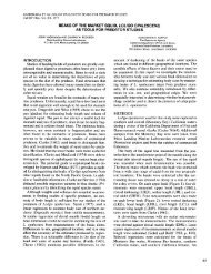
~ \METHOT: FRAME TRAWL<strong>CalCOFI</strong> Rep., <strong>Vol</strong>. XXVII, <strong>1986</strong>__III~ 3 -~- 2 ~,-/ \/ \- - - ~ ~ ~ ~ ~ _ _ _ _ _ _ _ _ _ _ ~ _ ~\ ? /I .Corner Attachment,see detail B/f'\ .j.,1./' 1 ',?an Bridle Attachment,+' -I- ',\ I /see detail A \j/'1 ~- 224nI1IIII~ _ _ _ _ _ _ _ _ _ _ _ ~ ~ ~ _ ~ ~ ~Figure 4 Dimensions of the frame trawl with 5 m2 mouth area See Figure 5 forconstruction details(0.25-inch) plate steel (Figure 4). U-shaped bridleattachments made of 1.3-cm (0.5-inch) steel rod arewelded to a reinforced section of the midpoint of eachside (Figure 5). A corner bracket of 0.95-cm (0.375-inch) steel is welded to each end of the top and bottomand bolted to the two sides. The total mass of the framein air is 106 kg; this could probably be safely reducedby narrowing the plate steel to about 7.5 cm.The depressor is a dihedral, as designed by Isaacs andKidd (Figure 6). Its dimensions are 2.44 m x 0.61 m(8 ft X 2 ft). The depressor used in the frame trawldiffers from the original Isaacs-Kidd depressor in thebridle attachment. The original design had an asymmetrictriangle attached by hinges to each end of thedepressor. The bridle was attached to the forwarddirectedapex of the triangles, and the net was attachedto the trailing edge of the depressor. The triangulararms were shaped so that the depressor would maintainan angle of attack (45") that maximized the downwardforce.The frame trawl has nothing attached to the trailingedge of the IK depressor; therefore the shape of the triangulararms must be modified to maintain the 45" angleof attack. Trials with a small model in a laboratoryflume indicated that an isoceles triangle is a suitableshape, but the angle of attack of this modified IKdepressor varies with tow speed. At zero speed, orwhen the depressor is very heavy, it will hang straightdown with no angle of attack and generate nodownward force other than its weight. At very highspeed or when it has negligible weight, the depressorswings farther back and up until it is vertical (90" angleof attack) and generates maximum drag but no1'downward component to this drag. The mass of thedepressor (65 kg in air) gives it an intermediate angle ofattack. At a speed of 2.0 m/sec the 5-m2 frame trawldives deeper if a 35-kg (75-lb) weight is added to thedepressor; the scope (ratio of wire out to net depth) wasabout 3.0 with the weight attached and 4.0 without theweight. The added weight brings the depressor's anglecloser to the 45" optimum. A steep wire angle (lowscope) is desirable because it moves the bridle fartherout of the mouth opening (Figure 2).The two floats are heavy-duty vinyl fishing floats.Each has a volume of 200 liters.The bridle is constructed of 11-mm (7/16-inch) cable.The main bridle consists of two 10-m sections(Figure 7). At one end they come together at a swivel,which is connected to the towing cable. The oppositeends of the main bridle sections terminate at swivelsattached to the U-shaped brackets inside the frame.These swivels at the brackets may be unnecessary iftorque-balanced cable is used for the bridle. Attachedto the U-shaped brackets on the trailing edge of theframe are 1.5-m sections of cable that terminate withquick-release connectors. These connectors can beattached either to the modified IK depressor or to thefloats. The total mass of the bridles is 32 kg.The net is constructed of knotless black nylon 1%inch stretch mesh (2 mm x 3 mm oval pores) and blacknylon webbing (5-cm width, seat belt strap material).There are eight longitudinal straps and nine circumferentialstraps (ribs). The mesh material is sandwichedbetween two layers of strap material, and the entiresandwich is sewn through with zigzag stitching. Thenet is attached to the frame by extending the eight longitudinalstraps about 50 cm beyond the mouth of thenet (Figure 8). Heavy, 10-mm (3/8-inch) grommets areset in these strap extensions and in the mouth rib. Thestraps are looped around the frame, and the grommetsin the strap are bolted to the grommets in the mouth rib.The mesh has low porosity, about 23%, and the lengthof the net is 10 m, so the ratio of pore area to mouth areais low (1.6) when allowance is made for the substantialarea occluded by straps. Increasing the net length to 13m and reducing the number of ribs to two (plus the ribaround net mouth) would increase the ratio of pore areato mouth area to about 2.6.The terminal end of the net is attached to a section of20-cm-diameter plastic pipe. A cod end constructed of0.505-mm mesh is attached to the terminal end of thepipe with a band clamp.The net of 2-mm mesh sandwiched between 5-cmwidenylon straps has proved difficult to repair. Rips inthe net often require replacing sections of the straps,and it is difficult to achieve sufficient strength in longitudinalstrap junctions that are resewn.<strong>27</strong>1