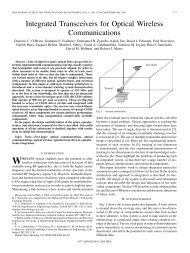
Introduction to OPNET Modeler
Introduction to OPNET Modeler
Introduction to OPNET Modeler
- No tags were found...

You also want an ePaper? Increase the reach of your titles
YUMPU automatically turns print PDFs into web optimized ePapers that Google loves.
1572<strong>Introduction</strong> <strong>to</strong> <strong>OPNET</strong> <strong>Modeler</strong> ®CONFIDENTIAL — RESTRICTED ACCESS:This information may not be disclosed, copied, or transmitted in any format without the prior written consent of <strong>OPNET</strong> Technologies, Inc.© 2010 <strong>OPNET</strong> Technologies, Inc.
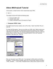
1572 <strong>Introduction</strong> <strong>to</strong> <strong>OPNET</strong> <strong>Modeler</strong> ®Lab 1: Workspace NavigationPurpose: To provide hands-on experience exploring a completed network. You will practice loadinga map, zooming, navigating through subnets, viewing the attributes of a node, and opening thecorresponding node models and process models.Time allotted: 15 minutes1) Open the project: choose Ctrl+O. For “Files of Type”, make sure Project is selected, and thendrill down in<strong>to</strong> the project_environment_ref.project folder. Open the project“project_environment_ref”..2) Practice moving between subnets.a. To enter a subnet, simply double-click on the subnet. Double-click on the “NorthAmerica” subnet icon <strong>to</strong> enter it.b. To return <strong>to</strong> the upper, or “parent” subnet:1. Right-click anywhere in the workspace (except on an icon), and choose “Go <strong>to</strong>Parent Subnet”.OR2. Click once (do not double-click) on the <strong>to</strong>olbar but<strong>to</strong>n:CONFIDENTIAL – RESTRICTED ACCESS: This information may not be disclosed, copied, or transmitted in any format without the prior written consent of <strong>OPNET</strong> Technologies, Inc.© 2008 <strong>OPNET</strong> Technologies, Inc.1
1572 <strong>Introduction</strong> <strong>to</strong> <strong>OPNET</strong> <strong>Modeler</strong> ®3) Use zooming features <strong>to</strong> identify U.S. cities: From the <strong>to</strong>p level (keep going <strong>to</strong> “parent subnet”until you cannot go any further), enter the subnet labeled “North America”, and then enter the“United States” subnet. Now use the various zoom features <strong>to</strong> identify each subnet.a. Zoom but<strong>to</strong>n: If you choose Zoom > To Rectangle from the View menu or click on theZoom <strong>to</strong> Rectangle but<strong>to</strong>n on the <strong>to</strong>olbar, you can click and drag a rectangle in theworkspace <strong>to</strong> define a region <strong>to</strong> be magnified.b. Zoom Out (on the <strong>to</strong>olbar).c. Page-Up and Page-Down keys (or the scroll wheel on your mouse).4) Add a MIF map image.a. Click on View > Background > Add MIF Map….b. Click on usa_highway (at first you will not see a difference).c. Click Close.5) Adjust the “layers” of the background images so that the highways are on <strong>to</strong>p.a. Click on View > Background > Set Properties.1. Select the MIF Map (usa_highway) layer.2. Click the Move Forward but<strong>to</strong>n twice <strong>to</strong> place it just before “BackgroundImages in the list.3. You should see the screen below.4. Close the Background Properties dialog box.CONFIDENTIAL – RESTRICTED ACCESS: This information may not be disclosed, copied, or transmitted in any format without the prior written consent of <strong>OPNET</strong> Technologies, Inc.© 2008 <strong>OPNET</strong> Technologies, Inc.2
1572 <strong>Introduction</strong> <strong>to</strong> <strong>OPNET</strong> <strong>Modeler</strong> ®6) One of the common things you will do with <strong>Modeler</strong> is <strong>to</strong> change the attributes of an object.Let’s practice this by changing the Datagram Switching Rate on the router in Chicago.a. Find and enter the Chicago subnet. Remember, <strong>to</strong> enter a subnet, double-click it.b. Right-click on the router and choose Edit Attributes from the menu.c. Expand the attribute IP by clicking on the plus sign <strong>to</strong> the left of it, and then expand theattribute IP Processing Information.d. Change the value of Datagram Switching Rate <strong>to</strong> 250,000.e. Click OK accept the change.CONFIDENTIAL – RESTRICTED ACCESS: This information may not be disclosed, copied, or transmitted in any format without the prior written consent of <strong>OPNET</strong> Technologies, Inc.© 2008 <strong>OPNET</strong> Technologies, Inc.3
1572 <strong>Introduction</strong> <strong>to</strong> <strong>OPNET</strong> <strong>Modeler</strong> ®7) Double-click on the router <strong>to</strong> view its node model. Later labs will show you how <strong>to</strong> create andedit a node model.8) Double-click on the processor labeled IP at the center of the router. This is the process model forthat queue. Later labs will show you how <strong>to</strong> create and edit a process model.9) Close all edi<strong>to</strong>rs.End of Lab 1CONFIDENTIAL – RESTRICTED ACCESS: This information may not be disclosed, copied, or transmitted in any format without the prior written consent of <strong>OPNET</strong> Technologies, Inc.© 2008 <strong>OPNET</strong> Technologies, Inc.4
1572 <strong>Introduction</strong> <strong>to</strong> <strong>OPNET</strong> <strong>Modeler</strong> ®Lab 2: Creating a Packet FormatPurpose: To create a new packet formatTime allotted: 10 minutes1) Select Ctrl+N. Under the pull-down menu, choose Packet Format (the fourthchoice from the bot<strong>to</strong>m).2) Left-click on the Create New Field but<strong>to</strong>n, and then leftclickin the workspace <strong>to</strong> create a field. You will notice that your mouse cursor isstill ready <strong>to</strong> create another packet field. In the space underneath the previousfield, left-click again <strong>to</strong> create another packet field. Once you have the two packetfields, right-click <strong>to</strong> s<strong>to</strong>p dropping packet fields. You should have somethinglike the following:3) Right-click on field_0 <strong>to</strong> access its attributes; set the name <strong>to</strong> Source Node, andthe size <strong>to</strong> 64 bits, then click OK.4) Right-click on field_1 <strong>to</strong> access its attributes; set the name <strong>to</strong> Destination Node,and the size <strong>to</strong> 64 bits, and then click OK.CONFIDENTIAL INFORMATION: DO NOT DISCLOSE, FORWARD, DISTRIBUTE, SHARE, OR MAKE COPIES OF THIS DOCUMENT IN WHOLE OR IN PART.© Copyright 2003 <strong>OPNET</strong> Technologies, Inc.Page 5
1572 <strong>Introduction</strong> <strong>to</strong> <strong>OPNET</strong> <strong>Modeler</strong> ®5) Save the packet: Choose File > Save and name the packet_trans_pkt (for example, if your initials were abc, you wouldname the packet format abc_trans_pkt).You have now created a new packet format with two headers: Source Node andDestination Node. Each is 64 bits in size, for a <strong>to</strong>tal of 128 bits. When we actuallycreate an instance of this packet in a simulation, we can also set the payload size. Wewill learn how a model creates a packet based on this packet format in later labs.6) Close the Packet Format Edi<strong>to</strong>r.End of Lab 2CONFIDENTIAL INFORMATION: DO NOT DISCLOSE, FORWARD, DISTRIBUTE, SHARE, OR MAKE COPIES OF THIS DOCUMENT IN WHOLE OR IN PART.© Copyright 2003 <strong>OPNET</strong> Technologies, Inc.Page 6
1572 <strong>Introduction</strong> <strong>to</strong> <strong>OPNET</strong> <strong>Modeler</strong> ®Lab 3: Creating a Node ModelPurpose: Create two node models, one representing the transmitter node in Washing<strong>to</strong>nDC, and the other representing the receiver node in PhiladelphiaTime allotted: 30 minutesNote: Throughout this lab and others, screenshots have been included. As you are goingthrough the steps in the labs, look for these <strong>to</strong> help guide you.Part 1: Create the Transmitter Node.Build a node model <strong>to</strong> represent the transmitter of bank transactions originating inWashing<strong>to</strong>n, D.C.1) Select Ctrl+N, select Node Model from the pull-down list.2) You will create a node model that looks like the diagram below, using the but<strong>to</strong>nscircled. We will have a simple packet genera<strong>to</strong>r sending packets <strong>to</strong> a transmitter.3) Create a processor: Click the Create Processor but<strong>to</strong>n on the <strong>to</strong>olbar and leftclickin the workspace. Right-click <strong>to</strong> s<strong>to</strong>p creating processor modules.4) Create a point-<strong>to</strong>-point transmitter: Click the Create Point-<strong>to</strong>-point Transmitterbut<strong>to</strong>n on the <strong>to</strong>olbar and left-click in the workspace. Right-click <strong>to</strong> s<strong>to</strong>pcreating transmitter modules.5) Create packet stream: Click the Create Packet Stream but<strong>to</strong>n on the <strong>to</strong>olbar andleft-click on the processor and then the transmitter. Right-click <strong>to</strong> s<strong>to</strong>p creatingpacket streams.CONFIDENTIAL INFORMATION: DO NOT DISCLOSE, FORWARD, DISTRIBUTE, SHARE, OR MAKE COPIES OF THIS DOCUMENT IN WHOLE OR IN PART.© Copyright 2003 <strong>OPNET</strong> Technologies, Inc.Page 7
1572 <strong>Introduction</strong> <strong>to</strong> <strong>OPNET</strong> <strong>Modeler</strong> ®6) We don’t need a mobile or satellite versions of this node, so we’ll only need astationary version of this node.a. Configure Node Interfaces: Select Interfaces > Node Interfaces.b. In the Node Types table, set the Supported column <strong>to</strong> No for both mobileand satellite.7) Change the icon for the node.a. Under the Default Icon column, click on fixed_comm.b. Change the icon palette <strong>to</strong> stdmod.c. Click on the icon called server_client.8) Click OK.9) Save the node model: choose File > Save and name the model_transmitter_nd.10) Configure the Processor. One of the most important attributes of a processor iswhat process model it uses. That determines its overall behavior and what otherattributes it can have. Right-click on the processor object and select EditAttributes, then enter these values:a. name = genb. process model = simple_sourcec. packet format = _trans_pkt (the packet format you createdbefore)d. Packet Interarrival Time:i. Distribution name = exponentialii. Mean outcome = 0.5e. Packet Size:i. Distribution Name = normalii. Mean Outcome = 3200iii. Variance = 400CONFIDENTIAL INFORMATION: DO NOT DISCLOSE, FORWARD, DISTRIBUTE, SHARE, OR MAKE COPIES OF THIS DOCUMENT IN WHOLE OR IN PART.© Copyright 2003 <strong>OPNET</strong> Technologies, Inc.Page 8
1572 <strong>Introduction</strong> <strong>to</strong> <strong>OPNET</strong> <strong>Modeler</strong> ®f. Verify it looks like the following (except with your packet format):g. Click OK.11) Set the data rate of the transmitter:a. Edit the attributes of the transmitter module.b. Set the name <strong>to</strong> trans.c. Expand the channel attribute, and then the Row 0 attribute.d. Set the data rate <strong>to</strong> unspecified (you’ll have <strong>to</strong> type it in).e. Click OK.CONFIDENTIAL INFORMATION: DO NOT DISCLOSE, FORWARD, DISTRIBUTE, SHARE, OR MAKE COPIES OF THIS DOCUMENT IN WHOLE OR IN PART.© Copyright 2003 <strong>OPNET</strong> Technologies, Inc.Page 9
1572 <strong>Introduction</strong> <strong>to</strong> <strong>OPNET</strong> <strong>Modeler</strong> ®Note: By entering a data rate of “unspecified”, we are telling the transmitter <strong>to</strong> use thedata rate of whatever link gets connected <strong>to</strong> it.Ultimately, statistic collection is done in the process models. Each process model canhave any number of statistics defined, so the processes you include in your node modeldetermine which statistics can be collected for the node. In our example, we only havetwo modules, and they are fairly simple, so the number of statistics defined in them isrelatively small. In more complex, sophisticated node models, there may be dozens, if nothundreds of statistics defined in the processes.It is up <strong>to</strong> the node model developer <strong>to</strong> determine which of these statistics are going <strong>to</strong> beavailable for collection <strong>to</strong> the user of the node. The Node Statistics table is the interfacefor which <strong>to</strong> specify these.12) Specify Node Statistics <strong>to</strong> collect queue size and throughput statistics (screenshotsfor the following steps are below)a. Select Interfaces > Node Statistics.b. Left-click in the Orig. Name column of the first row.c. Holding down the Control key, select the statistics:i. point-<strong>to</strong>-point transmitter.trans.channel [0].queue size (bits)ii. point-<strong>to</strong>-point transmitter.trans.channel[0].throughput(bits/sec)d. Click the Promote but<strong>to</strong>n.e. Click OK.We have now specified that when someone uses this node in their network, there will betwo statistics available for them <strong>to</strong> collect.13) Save the node model, and close the Node Edi<strong>to</strong>r window. The transmitter node isnow finished.CONFIDENTIAL INFORMATION: DO NOT DISCLOSE, FORWARD, DISTRIBUTE, SHARE, OR MAKE COPIES OF THIS DOCUMENT IN WHOLE OR IN PART.© Copyright 2003 <strong>OPNET</strong> Technologies, Inc.Page 10
1572 <strong>Introduction</strong> <strong>to</strong> <strong>OPNET</strong> <strong>Modeler</strong> ®Lab 3, Part 2: Create the Receiver Node1) Create a new node model (Ctrl+N - Node Model).2) Place one point-<strong>to</strong>-point receiver (not transmitter) and one processor in theworkspace.3) Connect them with a packet stream.4) Your node should look like this:5) Configure Node Interfaces (Interfaces > Node Interfaces).a. Just as you did for the transmitter node, set the “Node Types” <strong>to</strong> suppor<strong>to</strong>nly fixed nodes (you can refer back <strong>to</strong> the last lab if you don’t rememberhow).b. Change the icon for the node:i. Under default icon click on fixed_comm.ii. Choose the server icon from the icon palette stdmod.c. Click OK.6) Name the receiver object rec, and the processor object sink by right-clicking eachof them and choosing Set Name.7) Save the node model, again naming it with your initials:_receiver_nd.8) Select the Node Statistics of interest:i. Select Interfaces > Node Statistics.ii. Promote the statistic throughput (bits/sec) (for the receiver’schannel [0]).9) On the receiver module, set the data rate of the channel <strong>to</strong> be “unspecified”, asyou did when creating the transmitter node.10) Save the node, and close the Node Edi<strong>to</strong>r window.The Receiver Node is now complete.End of Lab 3CONFIDENTIAL INFORMATION: DO NOT DISCLOSE, FORWARD, DISTRIBUTE, SHARE, OR MAKE COPIES OF THIS DOCUMENT IN WHOLE OR IN PART.© Copyright 2003 <strong>OPNET</strong> Technologies, Inc.Page 11
1572 <strong>Introduction</strong> <strong>to</strong> <strong>OPNET</strong> <strong>Modeler</strong> ®Lab 4: Creating a Link ModelPurpose: To create a link modelTime allotted: 10 minutes1) Create a new link model (Ctrl+N - Link Model).2) Change “yes” <strong>to</strong> “no” for the “bus” and “bus tap” in the “Supported Link Types”table (we are creating a point-<strong>to</strong>-point link).3) Click on the attribute “data rate”, and enter 9600.A link model includes a set of attributes that specify which “Pipeline Stages” the link willuse. The Pipeline Stages specify how packets are transmitted from source <strong>to</strong> destinationover the physical layer. They determine such things as the transmission delay,propagation delay, bit errors, interference, etc. There are Pipeline Stages available <strong>to</strong>model the three types of transmission mechanisms available in <strong>Modeler</strong>:• Point-<strong>to</strong>-point• Bus• RadioWe will not go in<strong>to</strong> detail on exactly how these behave in this course, but it is available inthe product documentation and also in <strong>OPNET</strong>WORK sessions 1530 Modeling Cus<strong>to</strong>mWireless Effects — <strong>Introduction</strong> and 1580 Modeling Cus<strong>to</strong>m Wireless Effects —Advanced.For the purposes of this lab, we are going <strong>to</strong> set this link <strong>to</strong> use the default behavior forpoint-<strong>to</strong>-point links by setting these attributes:4) In the Attributes table, set the following Pipeline Stages:a. ecc model = dpt_eccb. error model = dpt_errorc. propdel model = dpt_propdeld. txdel model = dpt_txdelCONFIDENTIAL INFORMATION: DO NOT DISCLOSE, FORWARD, DISTRIBUTE, SHARE, OR MAKE COPIES OF THIS DOCUMENT IN WHOLE OR IN PART.© Copyright 2003 <strong>OPNET</strong> Technologies, Inc.Page 12
1572 <strong>Introduction</strong> <strong>to</strong> <strong>OPNET</strong> <strong>Modeler</strong> ®Some of the Pipeline Stage models call some functions from an external code file“link_delay”. When you create a link that uses the above pipeline stages, you need <strong>to</strong> tell<strong>Modeler</strong> <strong>to</strong> “include” the code for that file when starting the simulation. Below is howyou declare an external code file in a link model.5) Include the link_delay external file.a. Choose File > Declare External Files….b. Find link_delay in the list.c. Click on the gray box <strong>to</strong> select it.d. Make sure you see the green check mark in the checkboxe. Click OK.6) Save the new link model with the name _pt_base_9600.7) Close the Link Edi<strong>to</strong>r.End of Lab 4CONFIDENTIAL INFORMATION: DO NOT DISCLOSE, FORWARD, DISTRIBUTE, SHARE, OR MAKE COPIES OF THIS DOCUMENT IN WHOLE OR IN PART.© Copyright 2003 <strong>OPNET</strong> Technologies, Inc.Page 13
1572 <strong>Introduction</strong> <strong>to</strong> <strong>OPNET</strong> <strong>Modeler</strong> ®Lab 5: Creating a Project and ScenarioPurpose: To create a project <strong>to</strong> include the bank network discussedTime allotted: 15 minutesIn previous labs, we created nodes <strong>to</strong> represent the Philadelphia bank and the Washing<strong>to</strong>n DC bank(_receiver_nd and _transmitter_nd). We also created a type oflink <strong>to</strong> connect them. We will now create this simple network, run a simulation, and view our results.1) Create a new project.a. Choose Ctrl+N > Project.b. Name the new project bank_net. Name the initial scenario baseline.c. When the Startup Wizard appears, select Quit.2) Zoom in on Wash/Phil. Region. (Remember how <strong>to</strong> zoom from Lab 1?)a. Click the Zoom <strong>to</strong> Rectangle but<strong>to</strong>n and draw a box around the region.b. Or, use the Page-Up and Page-Down keys <strong>to</strong> zoom in and out.CONFIDENTIAL – RESTRICTED ACCESS: This information may not be disclosed, copied, or transmitted in any format without the prior written consent of <strong>OPNET</strong> Technologies, Inc.© 2007 <strong>OPNET</strong> Technologies, Inc.Page 14
1572 <strong>Introduction</strong> <strong>to</strong> <strong>OPNET</strong> <strong>Modeler</strong> ®3) Open Object Palette by clicking on the fifth but<strong>to</strong>n on the <strong>to</strong>olbar.4) Create a cus<strong>to</strong>m Object Palette, so that only the nodes and links we need are in the palette.a. Click the but<strong>to</strong>n Open Palette in Icon View.b. Click the Configure Palette but<strong>to</strong>n.c. Click the Clear but<strong>to</strong>n.d. Click the Node Models but<strong>to</strong>n.i. Find the receiver node you created in an earlier lab in the list and change itsstatus from not included <strong>to</strong> included. The node should be named with yourinitials: _receiver_nd.ii. Find the transmitter node you created earlier, and change its status <strong>to</strong>included.e. Click the Link Models but<strong>to</strong>n and include _pt_base_9600.f. Select Save As in the Configure Palette dialog box.g. When prompted, name the palette Bank_net_palette.h. Click OK (Save window).i. Click OK again (Configure Palette window).j. Accept the default palette name and location.k. Your palette should look like this:CONFIDENTIAL – RESTRICTED ACCESS: This information may not be disclosed, copied, or transmitted in any format without the prior written consent of <strong>OPNET</strong> Technologies, Inc.© 2007 <strong>OPNET</strong> Technologies, Inc.Page 15
1572 <strong>Introduction</strong> <strong>to</strong> <strong>OPNET</strong> <strong>Modeler</strong> ®5) Place nodes and connect them:a. Place a _transmitter_nd near Washing<strong>to</strong>n, D.C., by dragging anddropping its icon from the Object Paletteb. Place a _receiver_nd near Philadelphia.c. Name the two WDC_src and Philly_dest.d. Draw a simplex link (_pt_base_9600) from Washing<strong>to</strong>n <strong>to</strong>Philadelphia (make sure you are not using the duplex link, which has an arrowhead atboth ends).6) Switch the Object Palette back <strong>to</strong> the treeview by clicking the upper-left but<strong>to</strong>n. The paletteshould now look like this:As you see, the Object Palette has two views: Icon View and Treeview. Both present the sameinformation, but in a different layout. Which one you use is up <strong>to</strong> you; just remember you canswitch between them by using the upper-left but<strong>to</strong>n.The Verify Links operation does a quick check on your network <strong>to</strong> make sure you haven’thooked up links <strong>to</strong> incompatible nodes. It checks things such as data rate and pro<strong>to</strong>col.7) Verify links.a. Under the Topology menu, you will see Verify Links… <strong>to</strong>ward the bot<strong>to</strong>m. You willalso notice it has a shortcut key: Ctl+L.b. Use Ctl+L <strong>to</strong> verify if your links are connected properly.c. If the link between Washing<strong>to</strong>n and Philadelphia becomes marked with a red “X”,check the following:i. Make sure you are using a simplex link.ii. Is the link pointing from Washing<strong>to</strong>n <strong>to</strong> Philadelphia?CONFIDENTIAL – RESTRICTED ACCESS: This information may not be disclosed, copied, or transmitted in any format without the prior written consent of <strong>OPNET</strong> Technologies, Inc.© 2007 <strong>OPNET</strong> Technologies, Inc.Page 16
1572 <strong>Introduction</strong> <strong>to</strong> <strong>OPNET</strong> <strong>Modeler</strong> ®iii. Is the Washing<strong>to</strong>n DC node of the type “_transmitter_nd”?iv. Is the Philadelphia node of the type “_receiver_nd”?d. If you can’t get “Verify Links” <strong>to</strong> be successful, a TA or the instruc<strong>to</strong>r can help you.Use the screenshot below <strong>to</strong> determine how the network is supposed <strong>to</strong> look.8) Save the project.Now that we have drawn the <strong>to</strong>pology, we need <strong>to</strong> tell <strong>Modeler</strong> what statistics we are interested incollecting.9) In the Project Edi<strong>to</strong>r, choose Choose Individual Statistics from the DES menu. This bringsup the Choose Results dialog box.10) In the Choose Results dialog box, select the following:a. Node Statisticsi. point-<strong>to</strong>-point receiver > throughput (bits/sec)ii. point-<strong>to</strong>-point transmitter > queue size (bits)iii. point-<strong>to</strong>-point transmitter / throughput (bits/sec)b. Link Statisticsi. point-<strong>to</strong>-point > utilizationCONFIDENTIAL – RESTRICTED ACCESS: This information may not be disclosed, copied, or transmitted in any format without the prior written consent of <strong>OPNET</strong> Technologies, Inc.© 2007 <strong>OPNET</strong> Technologies, Inc.Page 17
1572 <strong>Introduction</strong> <strong>to</strong> <strong>OPNET</strong> <strong>Modeler</strong> ®Your window should look like the following:11) Click OK.The node statistics available should look familiar. When we created the transmitter_nd andreceiver_nd nodes, these are the statistics we specified in the “Node Statistics” dialog box (see Lab#3). By selecting them there, we <strong>to</strong>ld <strong>Modeler</strong> that those were the statistics that would be of mostinterest <strong>to</strong> someone using that node. They therefore show up in the “Choose Individual Statistics”dialog box in the previous steps.You may remember that there were other statistics available, which we did not add <strong>to</strong> that list (again,see Lab 3 if you want <strong>to</strong> see the steps again). Where are these statistics?The statistics you do not add <strong>to</strong> the “Node Statistics” list (when creating a node model) are stillavailable for collection, it just requires a different method. If you want <strong>to</strong> collect a statistic that doesnot show up in the “Choose Results” dialog box, you need <strong>to</strong> either edit the node <strong>to</strong> “promote” thosestatistics, or use the Probe Edi<strong>to</strong>r. The Probe Edi<strong>to</strong>r will not be covered in this session.12) Configure and run the Simulation.a. Click on the Configure/Run Simulation but<strong>to</strong>n on the <strong>to</strong>olbar.b. Set the duration <strong>to</strong> 30 minutes.c. Click on the Run but<strong>to</strong>n in the dialog box.d. When the simulation is done, click the Close but<strong>to</strong>n.CONFIDENTIAL – RESTRICTED ACCESS: This information may not be disclosed, copied, or transmitted in any format without the prior written consent of <strong>OPNET</strong> Technologies, Inc.© 2007 <strong>OPNET</strong> Technologies, Inc.Page 18
1572 <strong>Introduction</strong> <strong>to</strong> <strong>OPNET</strong> <strong>Modeler</strong> ®Before looking at the graphs, let’s review the attributes of the Washing<strong>to</strong>n, D.C., node (packets/sec,size of the packets) and the link (data rate) <strong>to</strong> help predict what the results should be. Double-clickthe Washing<strong>to</strong>n D.C. node <strong>to</strong> open its node model, and edit the attributes of the gen module. This iswhat you should see:Also remember the data rate of the link is 9600 bps.• What should be the throughput (in bits/second) at the WDC transmitter? ________bits/second• What should be the throughput (in bits/second) at the Philadelphia receiver?________ bits/second• What should be the utilization of the D.C. <strong>to</strong> Philadelphia link? ________• Should the queue size of the WDC transmitter steadily increase? ________To figure answers, we need <strong>to</strong> look at the load offered <strong>to</strong> the 9600-baud modem at the WDC node.Load = (1 pk/ 0.5 sec)(3200 bits/pk) = 6400 bits/sec.Expected results:What is the throughput (in bits/second) at the WDC transmitter? 6400 bits/second Since theload is less than data rate of transmitter, throughput = load.What is the throughput (in bits/second) at the Philadelphia receiver?6400 bits/second Whatever is transmitted is received. For point-<strong>to</strong>-point links, throughput at atransmitter should always equal throughput at the respective receiver.What is the utilization of the D.C. <strong>to</strong> Philadelphia link?67% [Calculated by figuring load over capacity, (6400 bits/sec) / (9600 bits/sec).]CONFIDENTIAL – RESTRICTED ACCESS: This information may not be disclosed, copied, or transmitted in any format without the prior written consent of <strong>OPNET</strong> Technologies, Inc.© 2007 <strong>OPNET</strong> Technologies, Inc.Page 19
1572 <strong>Introduction</strong> <strong>to</strong> <strong>OPNET</strong> <strong>Modeler</strong> ®Does the queue size of the WDC transmitter steadily increase? No. Clearly, 6400 bits/sec is lessthan 9600 bits/sec.] In a later lab, we'll learn how <strong>to</strong> filter the raw data and take a running averageof this data <strong>to</strong> see if it is really increasing.13) Once the simulation is complete, graph the results for the statistics we collected, <strong>to</strong> verify ourpredictions.a. Click on the View Results but<strong>to</strong>n <strong>to</strong>ward the right side of the <strong>to</strong>olbar.b. In general, <strong>to</strong> view a statistic by itself in one graph, follow these steps:i. Uncheck other statistics you may already have checked.ii. Check the statistic of interest.iii. Choose a filter (average, As is, CDF, etc.).iv. Click the Show but<strong>to</strong>n.For instance, this shows what you would choose <strong>to</strong> get the graph for the throughput on the WDC_srctransmitter, using an “average” filter.StatisticFilter selectionThe above is the preview for the graph. Click the “Show” but<strong>to</strong>n on the bot<strong>to</strong>m right <strong>to</strong> display it in aseparate window, so you can choose a different stat.CONFIDENTIAL – RESTRICTED ACCESS: This information may not be disclosed, copied, or transmitted in any format without the prior written consent of <strong>OPNET</strong> Technologies, Inc.© 2007 <strong>OPNET</strong> Technologies, Inc.Page 20
1572 <strong>Introduction</strong> <strong>to</strong> <strong>OPNET</strong> <strong>Modeler</strong> ®c. Using the above method, graph the following statistics:i. Average of Object Statistics/Philly_dest/point-<strong>to</strong>-point receiver/throughputii. Average of Object Statistics/WDC_src/point-<strong>to</strong>-point transmitter/queue sizeiii. Average of Object Statistics/WDC_src/point-<strong>to</strong>-point transmitter/throughputiv. Average of Object Statistics/WDC_src->Philly_dest [0]/point-<strong>to</strong>-point/utilizationd. Let’s have <strong>Modeler</strong> arrange the panels for us.i. Select DES > Panel Operations > Arrange Panels > Tile.Your graphs should look similar <strong>to</strong> the figures below. The peaks and valleys may be different, butyou should be getting approximately the same averages:If your results do not look similar <strong>to</strong> these, a TA or the instruc<strong>to</strong>r can help you determine why.End of Lab 5CONFIDENTIAL – RESTRICTED ACCESS: This information may not be disclosed, copied, or transmitted in any format without the prior written consent of <strong>OPNET</strong> Technologies, Inc.© 2007 <strong>OPNET</strong> Technologies, Inc.Page 21
1572 <strong>Introduction</strong> <strong>to</strong> <strong>OPNET</strong> <strong>Modeler</strong> ®Lab 6: Using Multiple Random SeedsPurpose: To re-run the bank-net simulation using varying random seeds.At this point, the simulation has been run a single time. We will now run a series of simulationsusing a different random seed for each run. By plotting a single statistic per run, the sample mean ofthe link utilization, we can gain a better appreciation for the s<strong>to</strong>chastic nature of our traffic genera<strong>to</strong>r.1) Configure multiple Simulation runs.a. Click on the Configure/Run Simulation but<strong>to</strong>n on the <strong>to</strong>olbar.b. Verify the duration is set <strong>to</strong> 30 minutes.c. Select Enter Multiple Seed Values but<strong>to</strong>n.d. Enter 128 in the Value column.e. Enter 137 in the Limit column.f. Enter 1 in the Step column.g. Click on the OK but<strong>to</strong>n in the dialog box.The resulting Configure/Run DES dialog box should match the following:CONFIDENTIAL – RESTRICTED ACCESS: This information may not be disclosed, copied, or transmitted in any format without the prior written consent of <strong>OPNET</strong> Technologies, Inc.© 2007 <strong>OPNET</strong> Technologies, Inc.Page 22
1572 <strong>Introduction</strong> <strong>to</strong> <strong>OPNET</strong> <strong>Modeler</strong> ®We have now set up 10 simulation runs that will complete in order.2) Click on Run.3) Once the simulations are complete, graph the results for the statistics we collected <strong>to</strong> verifyour calculations.a. Click on the View Results but<strong>to</strong>n <strong>to</strong>ward the right side of the <strong>to</strong>olbar.b. Select the DES Parametric Studies Tab.c. Expand Scalar Statistics and expand Execution.d. Highlight seed and click the Set as X-Series but<strong>to</strong>n.e. Expand Object Statistics and expand WDC_src->Philly_dest and point-<strong>to</strong>-pointutilization.f. Highlight sample mean and click the Set as Y-Series but<strong>to</strong>n.End of Lab 6CONFIDENTIAL – RESTRICTED ACCESS: This information may not be disclosed, copied, or transmitted in any format without the prior written consent of <strong>OPNET</strong> Technologies, Inc.© 2007 <strong>OPNET</strong> Technologies, Inc.Page 23
1572 <strong>Introduction</strong> <strong>to</strong> <strong>OPNET</strong> <strong>Modeler</strong> ®Lab 7: Modifying a Process ModelPurpose: To expand our original bank network <strong>to</strong> include more sources and destinations, and <strong>to</strong>include a new switch node. We will modify an existing process model <strong>to</strong> match the behavior wewant from our new switch.Time allotted: 30 minutesThe bank’s new network looks like this:Before creating this <strong>to</strong>pology, we need <strong>to</strong> create a new node <strong>to</strong> represent our switch. Here are thespecs we have for this switch:• It is a stationary node that supports 4 inputs and 2 outputs• It takes a packet from any input port and sends it <strong>to</strong> a random output port• The internal queue behaves as acb_fifo, with a processing rate of 76,800 bits per secondCreate a new node model, _switch_node, that looks like the following picture. Thetransmitters and receivers should take any packet format and have a data rate of unspecified. Thequeue module uses the process acb_fifo, with a service rate of 76800.Try <strong>to</strong> create it without the step-by-step instructions on the following page. Refer back <strong>to</strong> Lab 3 forreminders on the general steps for creating a node model.CONFIDENTIAL – RESTRICTED ACCESS: This information may not be disclosed, copied, or transmitted in any format without the prior written consent of <strong>OPNET</strong> Technologies, Inc.© 2007 <strong>OPNET</strong> Technologies, Inc.Page 24
1572 <strong>Introduction</strong> <strong>to</strong> <strong>OPNET</strong> <strong>Modeler</strong> ®1) Create a new node model by choosing Ctrl+N – Node Model.2) Place and connect the appropriate modules.a. Place four point-<strong>to</strong>-point receivers as shown.b. Place a queue module as shown.c. Place two point-<strong>to</strong>-point transmitters.d. Connect the modules with packet streams.3) Edit the queue’s attributes.a. Change its process model from pc_fifo <strong>to</strong> acb_fifo.b. Set the service rate <strong>to</strong> 76800.c. Name the queue fifo_queue.4) Change the channel data rates.a. Select all the transceivers.b. Edit attributes of one of the transceivers.c. Select the Apply Changes <strong>to</strong> Selected Objects checkbox.d. Change the data rate of the channel from 1024 <strong>to</strong> unspecified.e. Click OK.5) In the Interfaces > Node Interfaces menu:a. Change mobile and satellite <strong>to</strong> no.b. Change the node icon <strong>to</strong> switch (under ).6) Save the node model as _switch_node.At first glance, this node model seems <strong>to</strong> be finished. However, the acb_fifo process model isdesigned <strong>to</strong> accept packets from any number of sources and au<strong>to</strong>nomously forward them <strong>to</strong> a singledestination module. In other words, if we leave it like it is, it will forward all packets <strong>to</strong> the firsttransmitter. What we want is for it <strong>to</strong> randomly choose between the two transmitters. We will need<strong>to</strong> create our own version of the acb_fifo process model <strong>to</strong> do this.CONFIDENTIAL – RESTRICTED ACCESS: This information may not be disclosed, copied, or transmitted in any format without the prior written consent of <strong>OPNET</strong> Technologies, Inc.© 2007 <strong>OPNET</strong> Technologies, Inc.Page 25
1572 <strong>Introduction</strong> <strong>to</strong> <strong>OPNET</strong> <strong>Modeler</strong> ®Lab 7, Part 2: Create a Modified acb_fifo Process ModelTo modify an existing model, we will follow these steps:• Open the model• Save a copy, giving it a new name• Modify the new modelCreate the modified acb_fifo process model.1) Choose Ctrl+O and select Process Model as the file type.2) Click the std but<strong>to</strong>n <strong>to</strong> take you <strong>to</strong> the folder that contains the standard model library.3) acb_fifo is in the “base” folder.4) Once you have the acb_fifo process model open, choose File > Save As.a. Click the op_models but<strong>to</strong>n <strong>to</strong> take you <strong>to</strong> your op_models folder.b. Name it _switch_process.CONFIDENTIAL – RESTRICTED ACCESS: This information may not be disclosed, copied, or transmitted in any format without the prior written consent of <strong>OPNET</strong> Technologies, Inc.© 2007 <strong>OPNET</strong> Technologies, Inc.Page 26
1572 <strong>Introduction</strong> <strong>to</strong> <strong>OPNET</strong> <strong>Modeler</strong> ®5) Open the svc_compl enter executive block by double-clicking on the <strong>to</strong>p half of thesvc_compl state.6) Modify line 7 <strong>to</strong> read op_pk_send_forced (pkptr, (int)op_dist_uniform (2.0));7) Save the enter executives window. Click Ctrl+S (in the Enter Execs window), and close theEnter Execs code block so you are back <strong>to</strong> the process model state machine.8) Since we are making modifications anyway, let’s change the default service rate <strong>to</strong> meet ourspecifications:a. Under the menu Interfaces, choose Model Attributes.b. Change the service rate default value from 9600 <strong>to</strong> 76800.c. Click OK.9) Under Interfaces > Process Interfaces, you will see a “Comments” block. In here, you willsee where it states that it forwards packets <strong>to</strong> a single destination. Change it <strong>to</strong> state that itwill randomly send it <strong>to</strong> one of two outgoing links. This step is not necessary for the process<strong>to</strong> work, but it is a good practice <strong>to</strong> get in<strong>to</strong>.10) Save the process model by clicking Ctrl+S.11) Compile it with the green but<strong>to</strong>n on the right of the taskbar.12) You should get a message like the this:If you get any errors, or you get the message “done with warnings”, double-check that you typed thecode in correctly.13) Close the Process Edi<strong>to</strong>r.CONFIDENTIAL – RESTRICTED ACCESS: This information may not be disclosed, copied, or transmitted in any format without the prior written consent of <strong>OPNET</strong> Technologies, Inc.© 2007 <strong>OPNET</strong> Technologies, Inc.Page 27
1572 <strong>Introduction</strong> <strong>to</strong> <strong>OPNET</strong> <strong>Modeler</strong> ®Now that we have a new process <strong>to</strong> replace acb_fifo, we need <strong>to</strong> update our switch node <strong>to</strong> use it.1) Open the project bank_net, if it’s not already open2) Add our new switch node <strong>to</strong> our object palette.a. Open the Object Palette (the far left but<strong>to</strong>n on the Project <strong>to</strong>olbar).b. Bank_net_palette should be highlighted, and you should see that your two nodemodels and your link model are in the palette.c. In the Search by name box at the <strong>to</strong>p, type switch_node, and then click the FindNext but<strong>to</strong>nd. Once you have located your _switch_node, right click it, and select Add <strong>to</strong>Default Palette: bank_net_palette.3) Choose Scenario > Duplicate Scenario. Name the new scenario switched.4) Change the switch model <strong>to</strong> use our new modified acb_fifo processa. Open the _switch_node node model.b. Modify the queue’s attributes <strong>to</strong> use the new process model.i. Edit the queue’s attributes.ii. Change the process model from acb_fifo <strong>to</strong> _switch_process.c. Save the node model, and close it.5) Add source, switch, and destination nodes <strong>to</strong> the network, and connect them with links:a. It is not necessary for your network <strong>to</strong> look exactly like the one shown at thebeginning of the lab, but these rules need <strong>to</strong> be followed:CONFIDENTIAL – RESTRICTED ACCESS: This information may not be disclosed, copied, or transmitted in any format without the prior written consent of <strong>OPNET</strong> Technologies, Inc.© 2007 <strong>OPNET</strong> Technologies, Inc.Page 28
1572 <strong>Introduction</strong> <strong>to</strong> <strong>OPNET</strong> <strong>Modeler</strong> ®i. There are four transmitter nodes.ii. There are twelve switch nodes.iii. There are three receiver nodes.iv. Each switch must have two outgoing links and no more than four incominglinks.v. Use Verify Links <strong>to</strong> help make sure you have proper connections.b. Name the servers Philly_dest, Philly_dest_0, and Philly_dest_1.6) Since you duplicated the previous scenario, statistics are already chosen. Run the simulation<strong>to</strong> collect the same statistics for this new <strong>to</strong>pology. Remember <strong>to</strong> change the seed value back<strong>to</strong> a single seed of 128.7) When the simulation is complete, use the View Results but<strong>to</strong>n <strong>to</strong> graph the Point-<strong>to</strong>-PointReceiver Throughput for the three destination nodes (results are from one <strong>to</strong>pology; yoursmay differ). To graph many statistics <strong>to</strong>gether on one panel, follow these steps:a. Unselect statistics you are not interested in.b. Select all of the statistics you want <strong>to</strong> view in one graph.c. Select Overlaid Statistics from the pull-down menu in the Presentation section.d. Select a filter (As Is, average, etc).e. Click on the Show but<strong>to</strong>n.8) Save your project.End of Lab 7CONFIDENTIAL – RESTRICTED ACCESS: This information may not be disclosed, copied, or transmitted in any format without the prior written consent of <strong>OPNET</strong> Technologies, Inc.© 2007 <strong>OPNET</strong> Technologies, Inc.Page 29
1572 <strong>Introduction</strong> <strong>to</strong> <strong>OPNET</strong> <strong>Modeler</strong> ®Lab 8: Creating a Process ModelPurpose: To create a new process model from scratch. You will learn how <strong>to</strong> write your ownstatistics in a process model.Time allotted: 30 minutesThere is more than one way <strong>to</strong> create any process model. The instructions in this lab will create thedesired model using three states, which will look like this:• The INIT state, specified as a forced (green) state, for initial operations, like initializingvariables and statistic “registration”.• ETE_Destroy, specified as a forced (green) state, <strong>to</strong> process a packet (in this case, computeits ETE delay and destroy it).• WAIT, specified as an unforced (red) state because the process is waiting for an interrupt.CONFIDENTIAL – RESTRICTED ACCESS: This information may not be disclosed, copied, or transmitted in any format without the prior written consent of <strong>OPNET</strong> Technologies, Inc.© 2007 <strong>OPNET</strong> Technologies, Inc.Page 30
1572 <strong>Introduction</strong> <strong>to</strong> <strong>OPNET</strong> <strong>Modeler</strong> ®1) Create a new process model (Ctrl+N - Process Model.)2) Create three states in the work space.3) Connect the states in the following manner.Note: Left-clicking along a path while drawing a transition will add vertices <strong>to</strong> your transition.When you reach the next state, left-click again and the transition will have a curved shape if youhave not drawn a straight line.a. Left-click on the Create Transition but<strong>to</strong>n. Starting at st_0, connect st_0 <strong>to</strong> st_1.b. Starting at st_1 create a transition <strong>to</strong> st_2.d. Starting at st_2, create a transition back <strong>to</strong> st_1.4) Right-click on each state and make the following changes.a. st_0i. Set Name <strong>to</strong> INIT.ii. Make status forced.b. st_1i. Set Name <strong>to</strong> ETE_Destroy.ii. Make status forced.c. st_2i. Set Name <strong>to</strong> WAIT.ii. Leave status unforced.5) Edit the attributes of the transition going from the “WAIT” state <strong>to</strong> the “ETE_destroy” state,and set the condition attribute <strong>to</strong>: PK_ARRIVAL(This is the name of the macro for this transition.)6) Double check your states look like the screenshot at the start of this lab.7) Click on the Header Block (HB) but<strong>to</strong>n. Enter the following line of code <strong>to</strong> define the macro:#define PK_ARRIVAL (op_intrpt_type () == OPC_INTRPT_STRM)8) Choose File > Save in the Header Block window.9) Save your progress thus far. Save the Process model with the name_ETE_Destroy.CONFIDENTIAL – RESTRICTED ACCESS: This information may not be disclosed, copied, or transmitted in any format without the prior written consent of <strong>OPNET</strong> Technologies, Inc.© 2007 <strong>OPNET</strong> Technologies, Inc.Page 31
1572 <strong>Introduction</strong> <strong>to</strong> <strong>OPNET</strong> <strong>Modeler</strong> ®We have now defined that the value of PK_ARRIVAL will be true if the interrupt type we get is astream interrupt. Otherwise, PK_ARRIVAL is false. You will see its usage later.Next, we will create some variables that our process will be using. Variables in a Process Model canbe declared as state, temporary, or global.- State variablei. Private <strong>to</strong> the processii. Retains its value between invocationsiii. Needed <strong>to</strong> s<strong>to</strong>re persistent informationiv. Declared in the State Variable Block- Temporary variablei. Private <strong>to</strong> the processii. Retains its value only until control is returned <strong>to</strong> the Simulation Kerneliii. Useful <strong>to</strong> support transient calculationsiv. Declared in the Temporary Variable Block- Global variablei. Provides means for multiple processes <strong>to</strong> s<strong>to</strong>re information in a commonlocationii. Declared in the Header Block10) Create Temporary Variablesa. Click the TV but<strong>to</strong>n and enter the following:b. Choose File > Commit or Ctrl-S (In the “temporary variables” dialog box).These are temporary variables because we do not need <strong>to</strong> remember their values from the lastinterrupt. Every interrupt we receive will give us new values for these. We will see them used laterin this lab.CONFIDENTIAL – RESTRICTED ACCESS: This information may not be disclosed, copied, or transmitted in any format without the prior written consent of <strong>OPNET</strong> Technologies, Inc.© 2007 <strong>OPNET</strong> Technologies, Inc.Page 32
1572 <strong>Introduction</strong> <strong>to</strong> <strong>OPNET</strong> <strong>Modeler</strong> ®11) Create State Variables:a. Click on the State Variables (SV) but<strong>to</strong>n.b. In the state variables table enter:i. Type = Stathandleii. Name = ete_gshc. Click OK.The <strong>OPNET</strong> data type “Stathandle” is used <strong>to</strong> s<strong>to</strong>re a “handle” or pointer <strong>to</strong> a statistic. We will usethis variable <strong>to</strong> write our statistic values throughout the simulation. Since we will be using thisStathandle throughout the simulation, we need <strong>to</strong> make it a State Variable, so we can refer <strong>to</strong> itwhenever we want <strong>to</strong> write a value <strong>to</strong> it.There are four steps required for writing out statistics in a process model:1. Create a State Variable of type Stathandle2. Declare the statistic (Under the Interfaces menu)3. Use op_stat_reg() <strong>to</strong> tie 1 and 2 <strong>to</strong>gether4. Use op_stat_write() <strong>to</strong> actually write values <strong>to</strong> itSteps 1 – 3 need only be done once in your code for each statistic. We will do this in our “INIT”state.For our End-To-End Delay Statistic, we have just finished step 1. Now for the rest:12) Declare the ETE Delay statistic.a. Select Interfaces > Global Statistics.b. In the Declare Global Statistics table enter the following:i. Stat Name = ETE Delayii. Draw Style = lineariii. Leave other settings at their default.c. Click OK. (This completes step 2 for using our ETE Delay stat.)Note: Note exactly how you typed in “ETE Delay”. The next step will refer <strong>to</strong> this text string, sothey must match exactly (capitalization, number of spaces between words, spelling, etc.).CONFIDENTIAL – RESTRICTED ACCESS: This information may not be disclosed, copied, or transmitted in any format without the prior written consent of <strong>OPNET</strong> Technologies, Inc.© 2007 <strong>OPNET</strong> Technologies, Inc.Page 33
1572 <strong>Introduction</strong> <strong>to</strong> <strong>OPNET</strong> <strong>Modeler</strong> ®13) Double-click on the <strong>to</strong>p half of the “INIT” state.a. Enter the following:/* Register handle for statistic collection. */ete_gsh = op_stat_reg("ETE Delay", OPC_STAT_INDEX_NONE, OPC_STAT_GLOBAL);Again, make sure the “ETE Delay” above matches exactly how you typed it in the previous stepb. Choose File > Commit or Ctrl-S (in the “Enter Execs” window). (This completesstep 3 for using our ETE Delay stat. The last step of statistic writing, usingop_stat_write, will be part of the next code block).14) Double-click the <strong>to</strong>p half of the ETE_Destroy state. This is the state that is going <strong>to</strong> handlegetting the packet, writing statistics, and destroying the packet.a. Enter the following in the Enter Execs window./* Get stream index number. */stream_index = op_intrpt_strm();/* Get pointer <strong>to</strong> packet from stream index. */pkptr = op_pk_get(stream_index);/* Get creation time of packet. */creation_time = op_pk_creation_time_get(pkptr);/* Get current simulation time. */current_time = op_sim_time();/* Calculate ETE Delay. */ete_delay = (current_time - creation_time);/* Write statistics. */op_stat_write(ete_gsh, ete_delay);/* Destroy packet. */op_pk_destroy(pkptr);b. Choose File > Commit (in the Enter Execs window).CONFIDENTIAL – RESTRICTED ACCESS: This information may not be disclosed, copied, or transmitted in any format without the prior written consent of <strong>OPNET</strong> Technologies, Inc.© 2007 <strong>OPNET</strong> Technologies, Inc.Page 34
1572 <strong>Introduction</strong> <strong>to</strong> <strong>OPNET</strong> <strong>Modeler</strong> ®15) Compile the Process Model.16) Close the Process Edi<strong>to</strong>r window.Compile theProcess Model byleft-clicking onthis but<strong>to</strong>n.Look for status and errormessages. If the compilerencounters any problems,compiler report windowswill open in the mainworkspace.If you get compile errors, try <strong>to</strong> figure out what the problem is, correct it, and recompile.Now that we have a new Process Model <strong>to</strong> calculate our ETE delay, we need <strong>to</strong> modify our_receiver_nd node model <strong>to</strong> use this new process.17) Open the bank_net project and switch <strong>to</strong> the baseline scenario.a. Ctrl+O > Project – bank_netb. Scenarios > Switch To Scenario – baselineCONFIDENTIAL – RESTRICTED ACCESS: This information may not be disclosed, copied, or transmitted in any format without the prior written consent of <strong>OPNET</strong> Technologies, Inc.© 2007 <strong>OPNET</strong> Technologies, Inc.Page 35
1572 <strong>Introduction</strong> <strong>to</strong> <strong>OPNET</strong> <strong>Modeler</strong> ®18) Double-click on the Philly_dest node <strong>to</strong> enter the Node Edi<strong>to</strong>r.19) Right-click on the sink module and edit its attributes.a. Change the following:i. name = ETE_Destroyii. process model = _ETE_Destroyb. Click OK.c. Save and close the Node Edi<strong>to</strong>r.We have now modified our destination node so that it will use our new process model instead ofthe standard “sink” model. Let’s test it out. First, let’s collect that statistic we have defined in ourprocess model…20) Choose the global statistic ETE Delay:a. DES > Choose Individual Statisticsb. Global Statistics > ETE Delay21) Save the project.22) Run the simulation. (Remember <strong>to</strong> change the seed value back <strong>to</strong> a single seed of 128.)CONFIDENTIAL – RESTRICTED ACCESS: This information may not be disclosed, copied, or transmitted in any format without the prior written consent of <strong>OPNET</strong> Technologies, Inc.© 2007 <strong>OPNET</strong> Technologies, Inc.Page 36
1572 <strong>Introduction</strong> <strong>to</strong> <strong>OPNET</strong> <strong>Modeler</strong> ®23) When the simulation is finished, graph the ETE Delay statistics.a. Click the View Results but<strong>to</strong>n.b. Graph Global Statistics > ETE Delay (Average).c. Graph Global Statistics > ETE Delay (As Is).24) What is the probability the ETE Delay will be less than one second? A CDF graph will showus…a. In the View Results window select: Global Statistics > ETE Delay (CumulativeDistribution [CDF]).b. Place the mouse pointer on the point where the blue curve intersects with the 1-second mark on the horizontal axis. The “<strong>to</strong>ol tips” box will appear and tell you thevalues of the horizontal and vertical axes where your mouse pointer is located.Did your results match the graphs below?What did you get for the following?The average end-<strong>to</strong>-end delay for all packets? ________The % of packets incurring an end-<strong>to</strong>-end delay of less than 1 second? ________%End of Lab 8CONFIDENTIAL – RESTRICTED ACCESS: This information may not be disclosed, copied, or transmitted in any format without the prior written consent of <strong>OPNET</strong> Technologies, Inc.© 2007 <strong>OPNET</strong> Technologies, Inc.Page 37