Virtex-à¸â6 ML605 Development Board with 4-à¸âDSP FMC-à¸â150 ...
Virtex-à¸â6 ML605 Development Board with 4-à¸âDSP FMC-à¸â150 ...
Virtex-à¸â6 ML605 Development Board with 4-à¸âDSP FMC-à¸â150 ...
- No tags were found...

You also want an ePaper? Increase the reach of your titles
YUMPU automatically turns print PDFs into web optimized ePapers that Google loves.
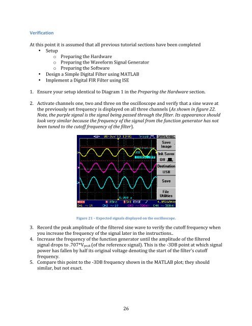
Verification At this point it is assumed that all previous tutorial sections have been completed • Setup o Preparing the Hardware o Preparing the Waveform Signal Generator o Preparing the Software • Design a Simple Digital Filter using MATLAB • Implement a Digital FIR Filter using ISE 1. Ensure your setup identical to Diagram 1 in the Preparing the Hardware section. 2. Activate channels one, two and three on the oscilloscope and verify that a sine wave at the previously set frequency is displayed on all three channels (As shown in figure 22. Note, the purple signal is the signal being passed through the filter. Its appearance should look very similar because the frequency of the signal from the function generator has not been tuned to the cutoff frequency of the filter). Figure 21 – Expected signals displayed on the oscilloscope. 3. Record the peak amplitude of the filtered sine wave to verify the cutoff frequency when you increase the frequency of the signal later in the instructions.. 4. Increase the frequency of the function generator until the amplitude of the filtered signal drops to .707*Vpeak (of the reference signal). This is the -‐3DB point at which signal power has fallen by half its original voltage denoting the start of the filter’s cutoff frequency. 5. Compare this point to the -‐3DB frequency shown in the MATLAB plot; they should similar, but not exact. 26