TRANS CAL Model 7280 - Burster
TRANS CAL Model 7280 - Burster
TRANS CAL Model 7280 - Burster
- No tags were found...

Create successful ePaper yourself
Turn your PDF publications into a flip-book with our unique Google optimized e-Paper software.
<strong>TRANS</strong> <strong>CAL</strong><strong>Model</strong> <strong>7280</strong>ContentsPage1. General.............................................................................................................................91.1 Application...........................................................................................................91.2 Description...........................................................................................................92. Preparations for use.....................................................................................................112.1 Unpacking the device........................................................................................112.2 Using the device for the first time......................................................................112.3 Mains operation.................................................................................................122.4 Safe and correct use..........................................................................................123. Controls and terminals.................................................................................................133.1 General...............................................................................................................133.2 Program overview..............................................................................................133.3 Description of the key........................................................................................143.4 Digital input........................................................................................................153.5 Pin assignment...................................................................................................164. Manual operation..........................................................................................................174.1 Menu description...............................................................................................174.2 Measuring with <strong>7280</strong>..........................................................................................194.2.1 Negative zero output......................................................................................... 194.2.2 Stored adjustment values................................................................................. 194.3 Sensor parameters.............................................................................................204.4 ADJUST - adjustment menu..............................................................................204.5 Adjustment procedure.......................................................................................214.6 Operating and function principle of the data logger in <strong>7280</strong> amplifier...............234.7 Adjustments in the LOGG mode........................................................................245. Remote...........................................................................................................................255.1 Serial interface...................................................................................................255.2 Read-out of current sensor parameters.............................................................265.3 Read-out complete status.................................................................................265.4 Read-out complete status.................................................................................275.5 Format of the serial interface output..................................................................295.6 Adjustments in the SCI mode............................................................................295.7 Transfer rate / specification RS232 (V.24) / USB................................................295.8 Link connection to USB.....................................................................................305.9 Measuring rate 1000/s and LOGG Mode 1 ms..................................................306. Technical data ..............................................................................................................317. Programmer example...................................................................................................338. Automatic OFF at battery / mains operation..............................................................37Page 7
<strong>Model</strong> <strong>7280</strong><strong>TRANS</strong> <strong>CAL</strong>ContentsSeite9. MISC ...........................................................................................................................379.1 Transportation....................................................................................................379.2 Initiation and setup.............................................................................................379.3 Normal operation...............................................................................................389.4 Maintenance and cleaning.................................................................................389.5 Disposal.............................................................................................................39Page 8
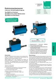
<strong>TRANS</strong> <strong>CAL</strong><strong>Model</strong> <strong>7280</strong>1. General1.1 ApplicationThe portable digital indicator model <strong>7280</strong> is a universal checking device for instrumentationexamination mechanical components like press, equipment of torque and so on. The employmenttakes place in the ranges quality assurance, start-up and process monitoring. By high measuringrates very fast reactions to the measuring signals are possible. A min./max. memory makesfurther areas of application possible for the equipment. A universally configurable data loggercan store measured values up to 15288. By the possibility 10 parameter sets to deposit, arepossible different calibration data such as sensor designation and physical units. Measuredvalues or logging values can be spent over RS232-/USB interface at a PC or a printer. So thatthe measurement chain is traceable, a proprietary calibration certificate can be provided. Thetraceability of the calibration exists over the used reference normal.1.2 DescriptionThe model <strong>7280</strong> is mobile by battery or accu, can be operated however also with an externalpower pack. A high measuring accuracy paired with fast measuring rate, 16 bit A/D converterand a microprocessor are ensured by the employment by highly precise amplifiers.The pocket model <strong>7280</strong> support sensors on strain gage basis and active sensors to 10 V /20 mA. Indicated on the 14 mm high LED main display will the current measured value, on asecond display directly under it can for example the peak value be read off. With the functiontare can be away-tared an existing basis load. For a force measuring chain we recommend toattach the tension and compression load cell model 8524 to the digital indicator. Dependingupon can be selected between measuring range of 500 N and 200 kN (divides into 9 stages).The reference measuring chain is completely configures and calibrated.Page 9
<strong>Model</strong> <strong>7280</strong><strong>TRANS</strong> <strong>CAL</strong>2.3 Mains operationMains operation:A plug-in power supply with controlled 6 V DC must be employed with min 1.5 A. For dischargedbatteries the charging current will be approx. 290 mA. In this way, the accumulators are alsoloaded simultaneously, also in the case of switched-off <strong>7280</strong>.During continuous operation on the net, it is recommended to remove the accumulators. For fastloading to 100 % of the accumulators, an external loader (e.g. Ansmann 4 - 6) is recommended.Prior to mains operation (disposable-) batteries must be removed from thedevice, as they would be destroyed by the charging process and thus leadto equipment damage !Accumulator operation:Use 4 x NiMH Mignon-Accumulators of min. 1600 mAh and 1.2 V correctly poled.Accumulator charge time:The accumulator charge time at accumulator-capacity of 2.7 Ah is approx. 9 - 10 h. At dischargedaccumulators, the constant charging rate is approx. 290 mA. Charged accumulators arerecognized by the Minus-Delta-Peak-Procedure (overload protection).Battery operation:Use 4 x Mignon/AA batteries with 1.5 VNever use a power supply plug when batteries are inserted !Voltage supply:If the admissible battery voltage falls below, the display starts to blink.Safe and correct useCaution:- Protect the device from moisture dew, rain, snow...- Protect the device from direct solar irradiation- Protect the device from dust and pollution- Protect the device from high and/or excessive ambient temperature- Protect the device from excessive vibrationPage 12
<strong>Model</strong> <strong>7280</strong><strong>TRANS</strong> <strong>CAL</strong>3.3 Description of the keysExample:In <strong>7280</strong> switch on- The <strong>7280</strong> is switched on, when ENTER button is pressed.Time and data- control or correct time and date in SYSTEM menuEdit language- Change in menu to 2 SYSTEM – 2.1 LANG. When ENTER button is pressed,<strong>7280</strong> is in selection mode. With the buttons PLUS and MINUS the language canbe selected. With ENTER the selected language will be saved. With ESC theselected language will be discarded.Edit time- Change in menu to 2 SYSTEM – 2.8 DATE. When ENTER button is pressedTIME will appear on LCD. Press ENTER and you can edit the time. With PLUSand MINUS button the hours can be adjusted. After ENTER the minutes can beadjusted with PLUS and MINUS button. With ENTER the selected time will besaved. With ESC the selected time will be discarded.Chance into the measure mode- From menu 1 MEASUR by pressing ENTER the list of all sensors is called up. By the keysPLUS and/or. MINUS a sensor parameter set is being chosen, then. By pressing ENTERthe <strong>7280</strong> is being adjusted to this sensor parameter set. By pressing ESC it is possibleto switch back to menu 1 MEASUR from any mode.Page 14
<strong>Model</strong> <strong>7280</strong><strong>TRANS</strong> <strong>CAL</strong>3.5 Pin assignmentPin assignment ofthe sensorsPage 16
<strong>TRANS</strong> <strong>CAL</strong><strong>Model</strong> <strong>7280</strong>4. Manual Operation4.1 Menu description1 MEASURE Measuring modeSENSOR__ Sensor selection for measuring mode, sensor 0 - 9Selection of the sensor parameter set of the measurement. Thesensor parameter set must comply with the connected sensor.2 SYSTEM All system parameters are stored in this menu column.2.1 LANG Language adjustmentThe menu language is available in English, German, French andSpanish.2.2 INFO Information query was factory-configured and is not modifiable.SW no.Firmware version2.3 SCI Interface configurationBAUDBaud rate adjustment; it must comply with the receiver (PC or printer).SCI MODE The interface configuration only refers to the measuring mode, notthe log mode!SCI off Interface switched offHAND When pressing ENTER in the measuring mode, a measured valueis displayed.AUTO 1 Interval time, adjustable from 10 ms to 1 h (at high measuring rateonly possible with the highest baud rate).TRIGGER At rising edge on the trigger input, in measuring mode a measuredvalue is displayed.INTERFAC Interface selectionUSB USB interface is activatedRS232 RS232 interface is activated2.4 RATE Measuring rate 1 and average valueRATEAVERAGE2.5 PASS Password queryRATEMeasuring rate adjustment, selectable from 1/s to 1000/s. For fastprocedures (screw joint, insert press...) always select a fast measuringrate, e.g. 1000/s, for very slow procedures select a small rate,e.g. 1/s.Average determination, the numbers indicate the average determinationby the amount of measurements. Applicable for e.g. vibrations,control oscillations...Entering password 9373 allows to change to menu 3 ADJUST. Here,the sensor parameters can be changed.2.6 LCD LCD contrast adjustmentIf the LCD becomes unreadable by external influences, e.g. solarradiation, heat or cold, the LCD contrast can be changed by pressingkey ▲ or ▼.1If the SCI → AUTO interval time is shorter than the adjusted measuring rate, the same measured valuewill be issued on the interface until a new value is entered.Page 17
<strong>Model</strong> <strong>7280</strong><strong>TRANS</strong> <strong>CAL</strong>2.7 LOGG Data logger adjustmentsLOGGMODE Data logger configurationLOGG off Off-switch for logger operation, measuring mode possible, only.Hand With each keystroke on ENTER a log value is accepted.AUTO Adjustment of the measurement intervals for the automatic measuredvalue storing.DIAGRAM With each rising edge of the trigger signal, a log value is accepted.WINDOW The window operation is started by a rising trigger edge and can befinished only by a falling edge. During this time, measured valuesare stored in 1 ms raster in the data logger.LOGGSEND Log values are issued through the interface, press ENTER twice.LOGGDEL Log values are deleted after a safety query. Before deleting, pleaseassure that the data was received.2.8 DATE Data and time adjustmentDATEDateTIMETime3 ADJUST AdjustmenuThis menu is active only, if the password has been entered in menumode 2.5 PASS. For the adjustment, the sensor must be connectedto the sensor socket.Sensor__ Sensor number or the name of the sensor which shall be adjusted.POINTDIS Final measurement value of the sensor with decimal indication e.g.1000; 100.0; 10.00; 1,000. The numerical values are variable, 4 digitsare available. Change to menu mode POINTSDIS. After pressingENTER, the final measurement value of the sensor can be entered.With keys ▲ and/or ▼ the first digit can be edited, go to the nextfigure by pressing ENTER. When all 4 digits are edited, the decimalpoint gets shifted by keys ▲ and/or ▼. Press ENTER to completethe entry, the final value will then be stored in the <strong>7280</strong> measuringamplifier.UNITEntry of the physical unit e.g. kg, Ncm, t, gr, kN, Nm, bar...ADJUST Sensor type selection (active with 100 % control signal, active without100 % control signal, passive with 100 % control signal, passivewithout 100 % control signal, 4-20 mA.DESIGName of the sensor e.g. sensor 1, 2, 3, DR-2112, silo, tank, mixer,scale 1, motor, test 1...Page 18
<strong>Model</strong> <strong>7280</strong><strong>TRANS</strong> <strong>CAL</strong>4.3 Sensor parametersAfter the password (9373) input in the system, the sensor can be applied in the calibrating menu.Following parameters are available:Sensor_ Sensor no 3 Sensor 0 - 9 possiblePOINTDIS 200.0 Adjust meas. range and decimal point (max. 9999)UNIT _kN 1 – 3 digit unit possibleDESIGN Squeezer up to 8 digit name (or numbers) freely optionalADJUST PAS_nCON Select passive without cal. control0 % LOAD Relieve sensor 0% value of sensor, indication 0 is assigned100 % CON Autom. calibration 100 % value of sensor will be assigned toindication 200 kNSAVE ENTER or ESC Confirm or reject4.4 ADJUST Adjustment menu3 ADJUST Adjustment menuThis menu is active only, if the password has been entered in menumode 2.5 PASS. For the adjustment, the sensor must be connectedto the sensor socket.Sensor_POINTDISPage 20Sensor number or the name of the sensor which shall be adjusted.Final measurement value of the sensor with decimal indication e.g.1000; 100,0; 10.00; 1.000; ...The numerical values are variable, 4 digits are available. Change tomenu mode POINTDIS. After pressing ENTER, the final measurementvalue of the sensor can be entered. With keys ▲ and/or▼ thefirst digit can be edited, go to the next figure by pressing ENTER.When all 4 digits are edited, the decimal point gets shifted by keys▲ and/or▼. Press ENTER to complete the entry, the final value willthen be stored in the <strong>7280</strong> measuring amplifier.
<strong>TRANS</strong> <strong>CAL</strong><strong>Model</strong> <strong>7280</strong>UNIT Entry of the physical unit, e.g. Kg, Ncm, t, kN, Nm, bar ...DESIGADJUSTName of the sensor, e.g. 1, 2, 3, DR 2112, silo, tank, mixer, scale1,motor, test1...Sensor type selection:ACTIVE without control signal, for transmitter 0-10 VCURRENT for transmitter 4-20 mA.PASSIVE without control signal, for strain gauge (load) sensors4.5 Adjustment procedureACT nCON Active sensor without 100 % control signalwith following adjustment possibilities:- adjust 0 % load and 100 % load- adjust 0 % load and enter hub(100 % load in V - 0 % load in V)- enter 0 % load in V and the hub(100 % load in V - 0 % load in V)Select between 0 % load or nominal value by pressing ▲ or ▼0 % LOAD unload sensoror NOMVALUE input of the nominal value in VSelect between load or nominal value by pressing ▲ or ▼100 % LOAD Adjustment by 100 % load (apply nominal load)or NOMVALUE input of the nominal value in VSAVE Query for takeover of the adjusted dataPAS nCON Passive Sensor without 100 % control signalwith following adjustment possibilities:- adjust 0 % load and 100 % load- adjust 0 % load and enter 100 % load in mV/V- enter 0 % load in mV/V and 100 % load in mV/VSelect between load or nominal value by pressing ▲ or ▼0 % LOAD unload sensor.or NOMVALUE input of the nominal value in mV/VSelect between 100 % load or nominal value by pressing ▲ or ▼100 % LOAD adjustment by load (apply nominal load).or NOMVALUE input of the nominal in mV/VSAVE Query for takeover of the adjusted dataPage 21
<strong>TRANS</strong> <strong>CAL</strong><strong>Model</strong> <strong>7280</strong>4.6 Operating and function principle of thedate logger in <strong>7280</strong> measuring amplifierThe data logger can, if the <strong>7280</strong> measuring amplifier is not in the measuring mode, be read bythe menu option 2.7 LOGG - SENDING or by the command „A“ via the interface. Outside of themeasuring mode the data logger is deleted only by the menu option 2.7 LOGG - DELETION.If the <strong>7280</strong> measuring amplifier is in the measuring mode, the data logger can be read with thecommand „A“ and be deleted with the command „B“.If the measuring mode is being switched on from the menu option 1 MEASURING-sensorselection, the starting time of the measurement, the current sensor designation, the final valueof the measuring range, the adjusted measuring rate and the logger mode (e.g.: AUTO 1 ms)are saved in the logger.NOTE: All previous measured values are deleted here!With the read-out of the data logger via the serial interface different adjustments of the <strong>7280</strong>are sent.a.)b.)c.)d.)e.)f.)g.)letter headstarting time of the measurementsensor designationdisplay final valueadjusted measuring rateadjusted logger modethereafter the measured valuesIn the HAND MODE the measured values are always logged with the time. With the data in theAUTOMODE the measured value is logged. A time can be assigned to each measured valueby the indicated starting time.Since in GRAPHS and in the WINDOW MODE trigger events smaller than 1 sec can occur, anadditional time log is not possible.Page 23
<strong>Model</strong> <strong>7280</strong><strong>TRANS</strong> <strong>CAL</strong>4.7 Adjustments in the LOGG modeLOGG OUTHANDAUTOGRAPHWINDOWHere the data logger is switched off. the logg mode in the measuringmode is switched to “LOGG OUT” as soon as the entire datalogger has been edited.In this mode a measured value is written into the data logger whenthe enter key was pressed at the <strong>7280</strong>. By an additional logg of time,there is a assignment for each measured value.In this mode in the adjusted delay a measured value is written intothe data logger. By the stored starting time there is a time assignmentfor each measured value.In this mode at a trigger event a measured value is written into thelogger. Since the trigger pulses occur in 10 ms raster, an additionallogg of the time is not possible. The flank of the trigger pulse muststand on HIGH for 4 ms at last. Afterwards on LOW for at least 6 ms.This mode reacts to in increasing and/or decreasing flanks. At anincreasing flank the logging of the measured values is started. Fromnow on the measured values are written in the data logger with 1ms raster. A decreasing flank ends the recording.Trigger SignalRead valuesMemory depth of data logger - see chapter 5.1Page 24
<strong>TRANS</strong> <strong>CAL</strong><strong>Model</strong> <strong>7280</strong>5.1 Serial interface5. RemoteFor the serial data transmission the <strong>7280</strong> measuring amplifier uses a RS232 oran USB interface. The PC manages the USB interface as a virtual COM port.For the use of the USB interface, must have a windows operating system (2k,XP, Vista, 7) and the burster präzsionsmesstechnik gmbh & co kg USB drivermust be installed (see chapter 3 - further documentation). After the driverinstallation, the virtual COM port can be used as described below.Transfer rate / specification RS232 (V.24) / USBParity:none}Number of data bits: 8 (1 Byte) 8N1Stop bit: 1Baud rate adjustable (2400, 4800, 9600, 19200, 38400, 115200 Baud)In the USB mode, the baud rate in the <strong>7280</strong> measuring amplifier and theconnected device must match.Protocol overviewVia the serial interface, the <strong>7280</strong> measuring amplifier can issue the measured values individuallyor automatically. The commands can be send to the <strong>7280</strong> measuring amplifier via a termalprogram or a PLC.Following commands are available:Command overviewASCII HEX Description in measuring not in measuringmodemodek 0x6B ENTER I 0x6C ▲ m 0x6D ▼ n 0x6E ESC A 0x41 Read-out data logger C 0x43 Read-out current sensor parameters D 0x44 Read-out status E 0x45 Read-out complete status g 0x67 Change protocol setup 0 0x30 Continuous measured value query (signed integer) 1 0x31 Query of max. value (signed integer) 2 0x32 Query of min. value (signed integer) 3 0x33 Tare of display 4 0x34 Reset max. value 5 0x35 Reset min. value 6 0x36 Actuate 100 % 100 % control signal -for sensors with 100 % control resistance7 0x37 Switch-off 100 % 100 % control signalfor sensors with 100 % control resistanceB 0x42 Delete data logger a 0x61 Write time b 0x62 Read-out time c 0x63 Write company head e 0x65 Write all sensor parameters (not supported yet) f 0x66 Read-all sensor parameters (not supported yet) In Menu 3: ADJUST → UNIT and ADJUST → DESIG theadjustments can be changed by the commands “I” and “m”Page 25
<strong>Model</strong> <strong>7280</strong><strong>TRANS</strong> <strong>CAL</strong>5.2 Read-out of current sensor parametersSensor designation 8 Byte ASCIIFinal displayed value 2 Byte compressed BCD-figureUnit 3 Byte ASCIISensor type and digit 1 Byte 0xAB: A ... Sensor type, B ... digit (binary coded)Sensor type:0xXXXX XXXX||||0000 ... active with 100% 100% control signal adjust 0% load and 100% load0001 ... active without 100% 100% control signal adjust 0% load and 100% load0010 ... active without 100% 100% control signal adjust 0% load and 100% load V0011 ... active without 100% 100% control signal adjust 0% load V and 100% load V0100 ... passive with 100% 100% control signal adjust 0% load and 100% load0101 ... passive without 100% 100% control signal adjust 0% load and 100% load0110 ... passive without 100% 100% control signal adjust 0% load V and 100% load mV0111 ... passive without 100% 100% control signal adjust 0% load mV and 100% load mV/V1000 ... current adjust 0% load and 100% load1001 ... current adjust 0% load and 100% load mA1010 ... current adjust 0% load mA and 100% load mADigit:0xXXXX XXXX|||||000 ... _5000___|001 ... _5,000__|010 ... _50,00__|011 ... _500,0__|100 ... 5,000___0%load 2 Byte HEX value (MSB/LSB)100% load 2 Byte HEX value (MSB/LSB)5.3 Read-out complete statusStatus 2 Byte general error condition of the <strong>7280</strong> measuring amplifierPage 26
<strong>TRANS</strong> <strong>CAL</strong><strong>Model</strong> <strong>7280</strong>5.4 Read-out complete statusStatus 2 ByteMeas. rate 1 Byte 0x01 ... 1000/sec0x02 ... 100/sec0x03 ... 10/sec0x04 ... 1/secAverage value 1 Byte 0x01 ... x/10x02 ... x/20x04 ... x/40x08 ... x/80x10 ... x/160x20 ... x/32SCI_MODE 1 Byte 0x00 ... interface is off mode0x04 ... hand mode0x08 ... automatic mode0x0C ... trigger modeSCI_MODE_DELAY 1 Byte 0x02 ...10 ms0x03 ... 100 ms0x04 ... 1 s0x05 ... 10 s0x06 ... 1 min0x07 ... 10 min0x08 ... 1 hLOGGMODE 1 Byte 0x00 ... logger is off modeLOGGMODE_DELAY 1Byte0x04 ... hand mode0x08 ... automatic mode0x0C ... DIAGRAM mode0x10 ... windows mode0x01 ... 1 ms0x02 ... 10 ms0x03 ... 100 ms0x04 ... 1 s0x05 ... 10 s0x06 ... 1 min0x07 ... 10 min0x08 ... 1 hLanguage 1 Byte 0x00 ... GERMANProtocol status0x02 ... ENGLISH0x04 ... FRENCH0x06 ... SPANISH1 Byte 0xXXXX XXXX (binary coded)|||| ||||General error condition of the <strong>7280</strong> measuring amplifier|||| |||1 ... do not send final character|||| ||1 ... send CR/LF|||| |1 ... send CR|||| 1 ... send LFWrite time:Write time is identical to data block receipt of time. However, the data block for writing is protectedwith a check sum and the referring weighted check sum.Read time:With following read-out:DAY.MONTH.YEAR2xSpaceHOURS:MINUTES:SECONDSPage 27
<strong>Model</strong> <strong>7280</strong><strong>TRANS</strong> <strong>CAL</strong>Write company head:The entry ends either if 256 characters are received or if the character ETX (0x03) Strg-C iscontained in the character string.Read company head:By this command, the company head, which is stored in the <strong>7280</strong> measuring amplifier, is read-out.Write all parameters:The writing data block of all sensor parameters is identical with the receiving data block forreading all parameters. However, for the writing of the sensor parameters a check sum andthe referring weighted check sum is required.Read all parameters:The read-out of all parameters from sensor 1 to sensor 10 occurs in following sequence:Sensor designationFinal displayed valueUnitSensor type (adjustment type) / decimal pointAdjustment values 0 % load, 100 % load with 2 Bytes eachSee command “read current sensor parameters”.Change protocol setup:Protocol status 1 Byte 0xXXXX XXXX (binary coded)|||| |||||||| |||1 ... do not send final character|||| ||1 ... send CR/LF|||| |1 ... send CR|||| 1 ... send LFCalculation of the check sum (CS) and the weighted check sum (gewCS):The calculation occurs via all parameter bytes (without the command byte). At the CS all bytesare added (overflows are not considered here). For the calculation of the gewCS, the CS isadded to the gewCS. At overflow, the gewCS is incremented by 1.Page 28
<strong>TRANS</strong> <strong>CAL</strong><strong>Model</strong> <strong>7280</strong>5.5 Format of the serial interface outputOperation via serial interface/USBOutput format in SCI mode:HANDSign, value, unit, time and CRLFAUTO 10 ms value (signed integer) and CRLF100 ms value (signed integer) and CRLF1 s Sign, value, unit, time and CRLF10 s Sign, value, unit, time and CRLF1 min Sign, value, unit, time and CRLF10 min Sign, value, unit, time and CRLF1 h Sign, value, unit, time and CRLFTRIGGERvalue (signed integer) and CRLFOutput format in LOGG mode:HANDAUTODIAGRAMWINDOWSign, measured value, unit, time and CRLFSign, measured value, unit and CRLFSign, measured value, unit and CRLFSign, measured value, unit and CRLF5.6 Adjustments in the SCI modeSCI off:HAND:AUTO:TRIGGER:With this adjustment, measured values transfer from the <strong>7280</strong> measuringamplifier is disabled, but the <strong>7280</strong> measuring amplifier can be controlledvia the <strong>7280</strong> commands.In this mode a measured value is issued via the serial interface whenENTER is pressed at the <strong>7280</strong> measuring amplifier.In this mode a measured value is issued via the serial interface in theadjusted delay.At a trigger event in this mode, a measured value is issued via theserial interface. The trigger pulses can occur in 10 ms raster. The flank ofthe trigger pulse must be on HIGH for at least 4 ms. Then it must beon LOW for at least 6 ms.5.7 Transfer rate / specification RS232 (V.24) / USBParity:noneNumber of data bits: 8 (1 Byte)Stop bit: 1Baud rate: adjustable (2400; 4800; 9600; 19200; 38400; 115200In the USB mode, the baud rate in the <strong>7280</strong> measuring amplifierand in the connected device must match.Page 29
<strong>Model</strong> <strong>7280</strong><strong>TRANS</strong> <strong>CAL</strong>5.8 Link connection to USBTo establish a connection between <strong>7280</strong> an PC, the user can install the USB driver on his PC.<strong>7280</strong> in 2.3 SCI/INTERFACE choose “USB” as the interface and in 2.3 SCI/BAUD set the desiredBAUD rate. Then connect the <strong>7280</strong> to your PC and start the software. Under the menu pointsettings/interface select the COM port with the name “XXXXX USB Sensor” and select in thesame menu the same BAUD rate as in <strong>7280</strong>. After that, the communication is established andcan be used exactly as directed by the RS232 interface.5.9 Measuring rate 1000/s and LOGG Mode 1 msDuring a measurement at a rate of 1000/s and active LOGGING mode with 1 ms can read viathe PC software in the section Data Logger no readings. This is because, that the measurementvalues are written 10 x faster in the devices internal memory, as they can be output via interface.Page 30
<strong>TRANS</strong> <strong>CAL</strong><strong>Model</strong> <strong>7280</strong>6. Technical DataAccuracy:Measuring rate:0.1 % F.S. ± 1 digit1 / 10 / 100 / 1000 sec.Average values: x/1, x/2, x/4, x/8, x/16, x/32Display counts:Zero point alignment:± 9.999 + 3 dig. unitautomatic/manualSensor selection for measurement mode: 10Data logger mode:window, diagram, manual, autoMemory values: max. 15288Bridge restance of the strain gauges:Sensitivity, passive:Sensitivity, active:Input resistance:Sensitivity, current:Connection technology:350 ... 2000 Ω± 3.3 mV/V± 10 Vapprox. 100 kΩ0/4 ... 20 mA an at 75 Ω2 or 3 wireVoltage supply passive/active:5 V / 20 mA ± 12 V / over 100 mA± 12 V altogether max. 120 mAWorking time with 50 % circle duration with accus:passive sensorsactive sensors> 20 h> 8 hNominal temperature range: + 15 °C ... + 35 °CRange of operating temperature: + 5 °C ... + 45 °CStorage temperature range: - 10 °C ... + 70 °CDimensions (D x W x H):Protection class:200 x 100 x 40 [mm]IP40Page 31
<strong>Model</strong> <strong>7280</strong><strong>TRANS</strong> <strong>CAL</strong>Given : Load cell model 8524-6050 strain gauge 350 ΩRange:50 kNOutput signal :1.5016 mV/VZero output without fitting parts: 0.0020 mV/VAfter selection of e.g. „SENSOR 1“ and after push of ENTER you get into the mode the sensorcan be applied in Adjust measuring range and decimal point (POINTDIS), UNIT and name ofthe sensor (DESIGN).POINTDISBy pressing ▲ or▼ you get to the following screens:UNITADJUSTDESIGNAfter pressing SENSOR 1 and ENTER you get the following screen e.g.10.00 NmNow in this example the number e.g. 50.00 can be set by pressing of ▲ or▼. If the beam isbelow the count this can be changed by pressing of ▲ or▼. The changed count is taken bypress of ENTER.After pressing 4 times ENTER you can set the decimal point by pressing ▲ oder▼. If the desireddecimal point reached you can taken this by press of ENTER.Now return to the following screen:By pressing ▲ you get to the next screen:POINTDISUNITPage 34
<strong>TRANS</strong> <strong>CAL</strong><strong>Model</strong> <strong>7280</strong>Given : Load cell model 8524-6050 strain gauge 350 ΩRange:50 kNOutput signal:1.5016 mV/VZero output without fitting parts: 0.0020 mV/VAfter pressing ENTER you get the following screen e.g._NmNow in this example the unit kN can be set by pressing ▲ or▼. If the beam is below the letterthis can be changed by pressing ▲ or ▼. The changed letter is taken by press of ENTER.Now return to the screen:UNITBy pressing 2 times ▲ you arrive the following screen:DESIGNAfter pressing ENTER you get the following screen:SENSOR 1Now it can be changed as for the designation of the UNIT e.g. Place 1 or similar.By pressing 1 times ▼ you arrive the following screen:ADJUSTAfter pressing ENTER you get the following screen:ACT nCONACT wCONPAS nCONPAS wCONCURRENTWith ▲ or▼ you can toggle through these screens.Page 35
<strong>Model</strong> <strong>7280</strong><strong>TRANS</strong> <strong>CAL</strong>Given : Load cell model 8524-6050 strain gauge 350 ΩRange:50 kNOutput signal :1.5016 mV/VZero output without fitting parts: 0.0020 mV/VWe choose for the above sensor the menu „PAS nCON“ ---> passive sensor without control.After pressing ENTER you get the following screen:0 % LOADLoad cell is connected andthe zero value is storedwith ENTER.Or after pressing ▼ you get the second entry menu (0 %)NOM VALThe characteristic datais entered accordingdata sheet. In this case0.020 mV/V.After pressing ENTER you can enter the zero value:0.020 mV/VAfter pressing ENTER you can enter the output signal (sensitivity (100 %) NOM VALUE, in thisexample 1.502 mV/V. If the entering of the value ended the next is “save?”. Press ENTER tocomplete the entry, the final value will then be stored in the <strong>7280</strong> measuring amplifier.After0 % LOADLoad cell is connected andthe zero value is storedwith ENTER.Now you can choose between two menusorthe second entry menu (100 %)100 % LOADNOM VALLoad cell is connected andthe 100 % value is storedwith ENTER.After pressing ENTER you can enter the 100 % value1.502 mV/VIf the entering of the value ended the next is “save?”. Press ENTER to complete the entry, thefinal value will then be stored in the <strong>7280</strong> measuring amplifier.Page 36
<strong>TRANS</strong> <strong>CAL</strong><strong>Model</strong> <strong>7280</strong>8. Automatic OFF at Battery /mains OperationWhen the <strong>7280</strong> is connected to the interface and there is no measurement, the automatic OFFfunction is still active.After a short time OFF is operative.Only during a measurement, this function is blocked. If there a short pause, the <strong>7280</strong> switchesitself OFF.9.1 Transportation9. MISCNote:Only transport well packed devicesThe device shall not be placed loosely in the packageProtect the device from humidity.9.2 Initiation and setupSafety measures before installing:Caution:The device may not be connected to mains, directly. The supply voltage is6 V DC with minimum 1.8 A.Cable connectionCaution:Never connect voltage levels to the unused pins!Page 37
<strong>Model</strong> <strong>7280</strong><strong>TRANS</strong> <strong>CAL</strong>9.3 Normal operationEMCCaution:The device may not be exposed to a higher EMC than determined by thestandard!CableCaution:Never separate the connectors by pulling on the cables; always pull the plug,directly!StorageNote:Only store the device in dry and dust-free rooms.Take out the batteries during the storage.9.4 Maintenance and cleaningCleaningCaution:Before cleaning, separate the device from voltage supply.Caution:Clean the housing with a soft and slightly damp cloth. Do not use solvents asthey may damage the front panel labeling and the display.When cleaning, ensure that no liquid enters the device or connections.Page 38
<strong>TRANS</strong> <strong>CAL</strong><strong>Model</strong> <strong>7280</strong>Battery changeCaution:Note the correct polarity of the batteries.Preventive maintenance and inspectionNote:Check the plug connections.RepairNote:The device do not contain any parts that need or can be serviced by the user.Repairs may exclusively ba carried out by burster präzisionsmesstechnik gmbh& co kg. If assumed that safe operation of the device is no longer possible,it must be taken out of operation immediately and also be secured againstinadvertent operation. Especially if:- the device is visibly damaged- the device is no longer functional- parts of the device are loose- the connecting lines show visible defects9.5 DisposalBattery disposal:As an end user, you are required by law (battery ordinance) to return all used batteriesand rechargeable batteries; the disposal through household waste is prohibited. Bybuying the herein described device you are concerned by this law. Please dispose ofyour batteries and rechargeable batteries correctly. Hand them to waste disposal siteseither at your premises or at our company or at any place where batteries/rechargeablebatteries are sold.Equipment disposal:Please fulfill your legal obligations and dispose of unserviceable equipment in accordancewith applicable legal requirements. Thus you contribute to environmentalprotection.Page 39