How to use the STM8L152x and STM8L162x LCD controllers
How to use the STM8L152x and STM8L162x LCD controllers
How to use the STM8L152x and STM8L162x LCD controllers
- No tags were found...

Create successful ePaper yourself
Turn your PDF publications into a flip-book with our unique Google optimized e-Paper software.
AN3114Contents5.2.1 <strong>LCD</strong> controller setup . . . . . . . . . . . . . . . . . . . . . . . . . . . . . . . . . . . . . . . 406 Conclusion . . . . . . . . . . . . . . . . . . . . . . . . . . . . . . . . . . . . . . . . . . . . . . . . 417 Revision his<strong>to</strong>ry . . . . . . . . . . . . . . . . . . . . . . . . . . . . . . . . . . . . . . . . . . . 42Doc ID 16829 Rev 2 3/43www.BDTIC.com/ST
List of tablesAN3114List of tablesTable 1. Reference letter for an alphanumeric character on <strong>LCD</strong> . . . . . . . . . . . . . . . . . . . . . . . . . . 26Table 2. <strong>LCD</strong>_RAM bits versus <strong>LCD</strong> PD-878 characters . . . . . . . . . . . . . . . . . . . . . . . . . . . . . . . . . 28Table 3. Reference letter for an alphanumeric character on cus<strong>to</strong>m <strong>LCD</strong> HXO5002B. . . . . . . . . . . 30Table 4. Cus<strong>to</strong>m <strong>LCD</strong> HXO5002B physical mapping . . . . . . . . . . . . . . . . . . . . . . . . . . . . . . . . . . . . 32Table 5. <strong>LCD</strong>_RAM bits versus cus<strong>to</strong>m <strong>LCD</strong> HXO5002B characters. . . . . . . . . . . . . . . . . . . . . . . . 33Table 6. Document revision his<strong>to</strong>ry . . . . . . . . . . . . . . . . . . . . . . . . . . . . . . . . . . . . . . . . . . . . . . . . . 424/43 Doc ID 16829 Rev 2www.BDTIC.com/ST
AN3114<strong>LCD</strong> controller drive signals2 <strong>LCD</strong> controller drive signals2.1 Single backplane <strong>LCD</strong> driveIn a single backplane drive, each <strong>LCD</strong> segment is connected <strong>to</strong> a segment line (Sx) <strong>and</strong> <strong>to</strong> abackplane (common line) common <strong>to</strong> all <strong>the</strong> segment lines. A display using S <strong>LCD</strong>segments is driven with S+1 MCU output lines (S segments + 1common). The backplane isdriven with a COM signal between 0 <strong>and</strong> V DD with a duty cycle of 50%.When switching on an <strong>LCD</strong> segment, a signal with opposite polarity <strong>to</strong> COM is sent <strong>to</strong> <strong>the</strong>corresponding Segment line. When <strong>the</strong> non-inverted COM signal-<strong>to</strong>-segment signal is sent<strong>to</strong> <strong>the</strong> Segment line, <strong>the</strong> <strong>LCD</strong> segment is off. Using an MCU, <strong>the</strong> I/O operates in outputmode at ei<strong>the</strong>r logic 0 or 1.Figure 3.<strong>LCD</strong> signals for direct drive Doc ID 16829 Rev 2 9/43www.BDTIC.com/ST
<strong>LCD</strong> controller drive signalsAN3114Discrimination ratio calculation for quadruplex mode:COM3 - SEG0 [ON] = (2VDD/3 - VDD/3) + (2VDD/3 - VDD/3) + (2VDD/3 - VDD/3) + (0 -VDD) + (VDD/3 - 2VDD/3) + (VDD/3 - 2VDD/3) + (VDD/3 - 2VDD/3) + (VDD - 0) => VDC = 0COM3 - SEG0 [OFF] = (2VDD/3 - VDD/3) + (2VDD/3 - VDD/3) + (2VDD/3 - VDD/3) + (0 - 0)+ (VDD/3 - 2VDD/3) + (VDD/3 - 2VDD/3) + (VDD/3 - 2VDD/3) + (0 - 0) => VDC = 0VSi ( ) 23⎛ VDD ------------⎞ 2 + ( VDD) 2 + 3⎛ – ---------------VDD ⎞ 2⎝n3 ⎠⎝ 3 ⎠+( – VDD) 2( )= --------------------- = ---------------------------------------------------------------------------------------------------------------------- = 0.577VDDn8V ON RMS∑VSi ( ) 24 VDD ------------⎝⎛ n3 ⎠⎞ 2 + 4 ⎛ – ---------------VDD ⎞ 2⎝ 3 ⎠( )= --------------------- = ------------------------------------------------------------ = 0.333VDDn8V OFF RMS∑D·= =0.395-------------- =0.176V----------------------------ON( RMS)V OFF( RMS)1.7322.4 Octaplex <strong>LCD</strong> driveIn an octaplex <strong>LCD</strong> drive, eight backplanes are <strong>use</strong>d. Each segment line is connected <strong>to</strong>eight <strong>LCD</strong> segments, which o<strong>the</strong>r side is connected <strong>to</strong> one, two, four or eight of <strong>the</strong> eightbackplanes. Consequently, only (S/8)+8 MCU pins are necessary <strong>to</strong> drive an <strong>LCD</strong> with S<strong>LCD</strong> segments. This mode is available only in medium+ <strong>and</strong> high density<strong>STM8L152x</strong>/<strong>STM8L162x</strong> devices. For example, <strong>to</strong> drive an <strong>LCD</strong> with 320 <strong>LCD</strong> segments(40 ×8), only 48 I/O ports are required (40 I/O ports <strong>to</strong> drive <strong>the</strong> segment lines <strong>and</strong> 8 I/Oports <strong>to</strong> drive <strong>the</strong> backplanes).Five different voltage levels have <strong>to</strong> be generated on <strong>the</strong> common lines: 0, V DD /4, V DD /2,3V DD /4 <strong>and</strong> V DD . The Segment line voltage levels are also 0, V DD /4, V DD /2, 3V DD /4 <strong>and</strong>V DD . The <strong>LCD</strong> segment is inactive if <strong>the</strong> RMS voltage is below <strong>the</strong> <strong>LCD</strong> threshold voltageV th , <strong>and</strong> is active if <strong>the</strong> <strong>LCD</strong> RMS voltage applied is above <strong>the</strong> threshold. Figure 9 showstypical backplane, Segment lines <strong>and</strong> <strong>LCD</strong> waveforms. The intermediate voltages V DD /4,<strong>and</strong> 3V DD /4 are required for backplane voltages. When a backplane or COM is active (0 Vduring an odd frame <strong>and</strong> V DD during an even frame), <strong>the</strong> o<strong>the</strong>rs are made inactive byapplying <strong>to</strong> <strong>the</strong>m 3V DD /4 during an odd frame <strong>and</strong> V DD /4 during an even frame.14/43 Doc ID 16829 Rev 2www.BDTIC.com/ST
AN3114<strong>LCD</strong> controller drive signalsFigure 8.Basic <strong>LCD</strong> segment lines connection in octaplex mode Doc ID 16829 Rev 2 15/43www.BDTIC.com/ST
<strong>LCD</strong> controller drive signalsAN3114Figure 9.<strong>LCD</strong> signals in octaplex mode 16/43 Doc ID 16829 Rev 2www.BDTIC.com/ST
AN3114Integrated <strong>LCD</strong> controllerFigure 11.Medium+ <strong>and</strong> high density <strong>LCD</strong> controller block diagram 3.1.1 Frequency genera<strong>to</strong>r blockThe first block of <strong>the</strong> <strong>LCD</strong> controller is <strong>the</strong> frequency genera<strong>to</strong>r. It consists of a 16-bit ripplecounter prescaler <strong>and</strong> a programmable clock divider with a divider fac<strong>to</strong>r ranging from 16 <strong>to</strong>31. It generates <strong>the</strong> <strong>LCD</strong> frequency, ck_div, starting from <strong>the</strong> input clock frequency, f <strong>LCD</strong>CLK .The 16-bit prescaler divides f <strong>LCD</strong>CLK by 1 up <strong>to</strong> 65536. The value can be configured through<strong>the</strong> PS[3:0] bits in <strong>the</strong> <strong>LCD</strong>_FRQ register. If a finer resolution rate is required, a seconddivider can be <strong>use</strong>d <strong>to</strong> fur<strong>the</strong>r divide fck_ps by a fac<strong>to</strong>r of 16 <strong>to</strong> 31. This second fac<strong>to</strong>r isconfigured through <strong>the</strong> DIV[3:0] bits in <strong>the</strong> <strong>LCD</strong>_FRQ register. fck_div is given by <strong>the</strong>following equation:f ck_div=f CLK<strong>LCD</strong>---------------------------------------------2 PS × ( 16 + DIV)Doc ID 16829 Rev 2 19/43www.BDTIC.com/ST
Integrated <strong>LCD</strong> controllerAN3114f frame is <strong>the</strong> operating frequency. It should be evaluated by taking in<strong>to</strong> account <strong>the</strong> operatingfrequency of <strong>the</strong> <strong>LCD</strong> device <strong>use</strong>d in application. This range is typically from 30 <strong>to</strong> 100 Hz. Itis a compromise between power consumption <strong>and</strong> an acceptable refresh rate.To generate f frame in <strong>the</strong> <strong>LCD</strong> operating frequency range using <strong>the</strong> prescaler <strong>and</strong> <strong>the</strong> divider,<strong>the</strong> <strong>LCD</strong>CLK input clock must be in <strong>the</strong> range of 16.384 KHz <strong>to</strong> 500 KHz. For more details,refer <strong>to</strong> section Clock control of <strong>the</strong> reference manual (RM0031). f frame is given by <strong>the</strong>following equation:f frame= f ck_div× dutywhere <strong>the</strong> duty can be static, 1/2, 1/3, 1/4 or 1/8.3.1.2 Common/segments drive blockThe second block of <strong>the</strong> <strong>LCD</strong> controller is <strong>the</strong> common/segments drive. It contains <strong>the</strong> timingcircuitry which allows <strong>to</strong> generate <strong>the</strong> appropriate waveforms <strong>to</strong> drive <strong>the</strong> common <strong>and</strong> <strong>the</strong>segments lines. Refer <strong>to</strong> <strong>the</strong> reference manual RM0031 (section 17.3.3 Common driver) foradditional details.This block also contains <strong>the</strong> <strong>LCD</strong>_RAM registers which bits correspond <strong>to</strong> <strong>the</strong> individualpixels <strong>to</strong> be displayed on <strong>the</strong> <strong>LCD</strong> device.In addition <strong>to</strong> <strong>the</strong> common/segments drive block features, a blink prescaler allows <strong>to</strong> select<strong>the</strong> blink frequency. This frequency is defined by setting <strong>the</strong> BLINKF[2:0] bits of <strong>the</strong><strong>LCD</strong>_CR1 register from 0 <strong>to</strong> 7. Refer <strong>to</strong> <strong>the</strong> reference manual RM0031 (section 17.3.2Frequency genera<strong>to</strong>r) for additional details.3.1.3 <strong>LCD</strong> contrast controller blockThe last block is <strong>the</strong> contrast controller. It plays a key role in <strong>the</strong> <strong>LCD</strong> controller since itallows <strong>to</strong> adjust <strong>the</strong> contrast <strong>to</strong> <strong>the</strong> optimal value depending on <strong>the</strong> trade-off between <strong>the</strong>power consumption <strong>and</strong> a satisfac<strong>to</strong>ry contrast level for <strong>the</strong> application.The contrast depends on <strong>the</strong> V <strong>LCD</strong> voltage level which ei<strong>the</strong>r internally generated by <strong>the</strong>booster or externally provided on <strong>the</strong> Vlcd pin.External V <strong>LCD</strong> voltage sourceThe external V <strong>LCD</strong> voltage source is selected by setting <strong>the</strong> V SEL bit <strong>to</strong> ‘1’ in <strong>the</strong> <strong>LCD</strong>_CR2register. When <strong>the</strong> external source is <strong>use</strong>d <strong>to</strong> generate V <strong>LCD</strong> , <strong>the</strong> contrast is controlled byvarying <strong>the</strong> dead time (up <strong>to</strong> seven phase periods) between each couple of frames where<strong>the</strong> COM <strong>and</strong> SEG values are low simultaneously.Internal V <strong>LCD</strong> voltage sourceThe internal booster is selected by clearing <strong>the</strong> V SEL bit in <strong>LCD</strong>_CR2. In this case, <strong>the</strong>contrast is controlled by adjusting V <strong>LCD</strong> by software from 2.6 <strong>to</strong> 3.3 V in medium density<strong>STM8L152x</strong> devices <strong>and</strong> from 2.6 <strong>to</strong> 3.5 V in medium+ <strong>and</strong> high density<strong>STM8L152x</strong>/<strong>STM8L162x</strong> devices in eight steps (see product datasheets).20/43 Doc ID 16829 Rev 2www.BDTIC.com/ST
AN3114Integrated <strong>LCD</strong> controllerGeneration of <strong>the</strong> <strong>LCD</strong> voltage levelsThe internal booster includes two resistive networks, one with low value resis<strong>to</strong>rs (R L ) <strong>and</strong>one with high value resis<strong>to</strong>r (R H ) which are respectively <strong>use</strong>d <strong>to</strong> increase <strong>the</strong> current duringtransitions <strong>and</strong> <strong>to</strong> reduce consumption in static state (see Figure 12).●The EN switch follows <strong>the</strong> rules below:– When <strong>the</strong> <strong>LCD</strong>EN bit in <strong>the</strong> <strong>LCD</strong>_CR3 register is set, <strong>the</strong> EN switch is closed.– When clearing <strong>the</strong> <strong>LCD</strong>EN bit in <strong>the</strong> <strong>LCD</strong>_CR3, <strong>the</strong> EN switch is open at <strong>the</strong> endof <strong>the</strong> even frame in order <strong>to</strong> avoid a medium voltage level different from 0 during<strong>the</strong> frame.The PON[2:0] (Pulse ON duration) bits in <strong>the</strong> <strong>LCD</strong>_CR2 register configure <strong>the</strong> time duringwhich R L is enabled (see Figure 10 <strong>and</strong> Figure 11) through a HD (high drive) when <strong>the</strong>levels of common <strong>and</strong> segment lines change. A short drive time decreases powerconsumption, but displays with high internal resistance may need a longer drive time <strong>to</strong>achieve a satisfac<strong>to</strong>ry contrast.The R L divider can be always switched on using <strong>the</strong> HD bit in <strong>the</strong> <strong>LCD</strong>_CR2 register.● The R L divider is enabled when <strong>the</strong> HD signal is set only for a short period of time when<strong>the</strong> levels of common <strong>and</strong> segment lines change. This time can be programmedthrough <strong>the</strong> Pulse ON bits (PON[2:0]) of <strong>the</strong> <strong>LCD</strong>_CR2 register. The HD signal follows<strong>the</strong> rules described below:– If <strong>the</strong> HD bit <strong>and</strong> <strong>the</strong> PON[2:0] bits in <strong>the</strong> <strong>LCD</strong>_CR2 are reset, <strong>the</strong>n <strong>the</strong> HD signalis open.– If <strong>the</strong> HD bit in <strong>the</strong> <strong>LCD</strong>_CR2 register is reset <strong>and</strong> <strong>the</strong> PON[2:0] bits in <strong>the</strong><strong>LCD</strong>_CR2 are different from 00, <strong>the</strong>n <strong>the</strong> HD signal is closed during <strong>the</strong> number ofpulses defined in <strong>the</strong> PON[2:0] bits.– If <strong>the</strong> HD bit in <strong>the</strong> <strong>LCD</strong>_CR2 register is 1, <strong>the</strong>n <strong>the</strong> HD signal is always closed.Doc ID 16829 Rev 2 21/43www.BDTIC.com/ST
Integrated <strong>LCD</strong> controllerAN3114Figure 12.Resistive network (internal booster) ● In case of 1/2 bias, one voltage level (1/2 V <strong>LCD</strong> ) is generated <strong>and</strong> node b voltage is 1/2V <strong>LCD</strong> .●In case of 1/3 bias, two intermediate voltage levels (1/3 V <strong>LCD</strong> , 2/3 V <strong>LCD</strong> ) are generated:– node a is 1/3 V <strong>LCD</strong>●– node b is 2/3 V <strong>LCD</strong>In case of 1/4 bias (medium+ <strong>and</strong> high density <strong>STM8L152x</strong>/<strong>STM8L162x</strong> devices only),three intermediate voltage levels (1/4 V <strong>LCD</strong> , 1/2 V <strong>LCD</strong> <strong>and</strong> 3/4 V <strong>LCD</strong> ) are generated:– node a is 1/4 V <strong>LCD</strong>– node b is 1/2 V <strong>LCD</strong>– node c is 3/4 V <strong>LCD</strong> .3.2 Optimizing power consumptionWhen <strong>the</strong> <strong>LCD</strong> controller operates in run mode, decreasing <strong>the</strong> power consumption resultsin a lower contrast. As a consequence, <strong>the</strong> contrast adjustment methods described inSection 3.1.3 can also be <strong>use</strong>d <strong>to</strong> adjust <strong>the</strong> power consumption.When <strong>the</strong> internal booster is <strong>use</strong>d, <strong>the</strong> power consumption can be reduced by minimizing<strong>the</strong> period of time during which <strong>the</strong> R L divider is enabled (drive time). <strong>How</strong>ever, <strong>the</strong> drivetime <strong>to</strong> achieve a satisfac<strong>to</strong>ry contrast may be longer with a high internal resistance.<strong>How</strong>ever, <strong>the</strong> <strong>STM8L152x</strong> <strong>and</strong> <strong>STM8L162x</strong> micro<strong>controllers</strong> allow <strong>the</strong> <strong>LCD</strong> controller <strong>to</strong>operate in all low power modes except for Halt mode.22/43 Doc ID 16829 Rev 2www.BDTIC.com/ST
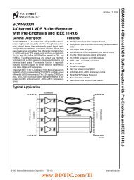
Displaying alphanumeric characters on <strong>the</strong> <strong>LCD</strong> glassAN3114Figure 14.<strong>LCD</strong> segments <strong>use</strong>d on <strong>the</strong> STM8L1526-EVALNote:Only <strong>the</strong> black alphanumeric characters are <strong>use</strong>d by this application note firmware <strong>to</strong> display<strong>the</strong> time. The red alphanumeric (position 6) is connected on <strong>the</strong> evaluation boardSTM8L1526-EVAL but not <strong>use</strong>d, <strong>and</strong> <strong>the</strong> white alphanumeric is not connected.Figure 15.Reference letters for an alphanumeric character on <strong>the</strong> PD-87824/43 Doc ID 16829 Rev 2www.BDTIC.com/ST
AN3114Displaying alphanumeric characters on <strong>the</strong> <strong>LCD</strong> glass4.2 Cus<strong>to</strong>m <strong>LCD</strong> glass HXO5002B <strong>use</strong>d on STM8L1528-EVALThe cus<strong>to</strong>m <strong>LCD</strong> glass HXO5002B mounted on <strong>the</strong> STM8L1528-EVAL is designed speciallyfor <strong>the</strong> <strong>LCD</strong> controller available in medium+ density <strong>STM8L152x</strong> devices <strong>and</strong> high density<strong>STM8L152x</strong>/<strong>STM8L162x</strong> devices. It is a combination of alphanumeric symbols <strong>and</strong> various<strong>use</strong>ful predefined symbols such as dot matrix, low-battery symbol, arrows (left, up, right,<strong>and</strong> down), ST logo... Figure 16 shows <strong>the</strong> layout for <strong>the</strong> cus<strong>to</strong>m <strong>LCD</strong> HXO5002B.The operating <strong>LCD</strong> mode is 1/8 duty <strong>and</strong> 1/4 bias. Each segment line can control up <strong>to</strong> eightpixels. The integrated <strong>LCD</strong> controller can control up <strong>to</strong> 320 <strong>LCD</strong> segments that can bedivided between alphanumeric symbols (7 x 16 pixels), dot matrix (10 x 19 pixels), lowbatterysymbol (4 pixels), arrows (4 pixels), antenna (6 pixels), ST logo (1 pixel) <strong>and</strong> 3 pixelsfor mA, µa <strong>and</strong> nA signs. In <strong>to</strong>tal, 320 <strong>LCD</strong> segments are controlled through eight COM <strong>and</strong>40 segment lines. Each segment line of <strong>the</strong> <strong>LCD</strong> glass is connected in <strong>the</strong> st<strong>and</strong>ardconfiguration. Figure 17 shows <strong>the</strong> reference segment lines for <strong>the</strong> cus<strong>to</strong>m <strong>LCD</strong> HXO5002B.Figure 16.Layout for <strong>the</strong> cus<strong>to</strong>m <strong>LCD</strong> HXO5002BFigure 17.Reference <strong>LCD</strong> segments for <strong>the</strong> cus<strong>to</strong>m <strong>LCD</strong> HXO5002BDoc ID 16829 Rev 2 25/43www.BDTIC.com/ST
Displaying alphanumeric characters on <strong>the</strong> <strong>LCD</strong> glassAN31144.3 Connecting <strong>the</strong> <strong>LCD</strong> glass PD-878 <strong>to</strong> <strong>the</strong> <strong>LCD</strong> controlleravailable inmedium density <strong>STM8L152x</strong> devicesTo display an alphanumeric character on <strong>the</strong> <strong>LCD</strong> glass display PD-878 available onSTM8L1526-EVAL, four common lines (COM) <strong>and</strong> four segment lines (SEG) are required.Table 1 shows <strong>the</strong> correspondence between each <strong>LCD</strong> segment <strong>and</strong> <strong>the</strong> reference letter on<strong>the</strong> <strong>LCD</strong> glass.Table 1.Reference letter for an alphanumeric character on <strong>LCD</strong>Couple (COM/SEG)<strong>LCD</strong> segment in <strong>LCD</strong> RAMReference letter for analphanumeric characterCOM0/SEG(n) <strong>LCD</strong> segment(n) XCOM0/SEG(n+1) <strong>LCD</strong> segment(n+1) ICOM0/SEG(n+2) <strong>LCD</strong> segment(n+2) ACOM0/SEG(n+3) <strong>LCD</strong> segment(n+3) HCOM1/SEG(n) <strong>LCD</strong> segment(n+28) FCOM1/SEG(n+1) <strong>LCD</strong> segment(n+1+28) JCOM1/SEG(n+2) <strong>LCD</strong> segment(n+2+28) BCOM1/SEG(n+3) <strong>LCD</strong> segment(n+3+28) GCOM2/SEG(n) <strong>LCD</strong> segment(n+56) ECOM2/SEG(n+1) <strong>LCD</strong> segment(n+1+56) KCOM2/SEG(n+2) <strong>LCD</strong> segment(n+2+56) CCOM2/SEG(n+3) <strong>LCD</strong> segment(n+3+57) LCOM3/SEG(n) <strong>LCD</strong> segment(n+84) DCOM3/SEG(n+1) <strong>LCD</strong> segment(n+1+84) NCOM3/SEG(n+2) <strong>LCD</strong> segment(n+2+84) DPCOM3/SEG(n+3) <strong>LCD</strong> segment(n+3+84) MNote:“n” values can be (0, 4, 8, 12, 16, 20, 24) respectively for alphanumeric character position(6, 5, 4, 3, 2, 1 <strong>and</strong> 0).The <strong>LCD</strong> segments are individually controlled by setting or clearing <strong>the</strong> corresponding bit of<strong>the</strong> <strong>LCD</strong> data registers (<strong>LCD</strong>_RAM[13:0]). The <strong>LCD</strong> controller module h<strong>and</strong>les <strong>the</strong> encodingof <strong>the</strong> physical drive waveforms <strong>to</strong> <strong>the</strong> <strong>LCD</strong> glass.The physical connections between each of <strong>the</strong> 16 segment digits, <strong>the</strong> segment lines <strong>and</strong> <strong>the</strong>common lines must be performed as shown in Figure 18.26/43 Doc ID 16829 Rev 2www.BDTIC.com/ST
AN3114Displaying alphanumeric characters on <strong>the</strong> <strong>LCD</strong> glassFigure 18.PD-878 physical connection for an alphanumeric characterTo be able <strong>to</strong> make an efficient <strong>LCD</strong> software driver <strong>and</strong> optimize <strong>LCD</strong> alphanumericcharacter coding in terms of code density, <strong>the</strong> matrix shown in Figure 19 has been chosen.Figure 19.PD-878 segment driver matrixEach matrix M element corresponds <strong>to</strong> one bit on <strong>the</strong> <strong>LCD</strong>_RAM[13:0] registers. To enableSEG(i) connected <strong>to</strong> COM(j), <strong>the</strong> “M[i][j]” element must be set <strong>to</strong> 1 <strong>and</strong> <strong>to</strong> disable it <strong>the</strong>“M[i][j]” element must be set <strong>to</strong> 0.The following structure provided in <strong>the</strong> <strong>LCD</strong> firmware allows <strong>to</strong> translate alphanumericcharacters from ASCII <strong>to</strong> <strong>LCD</strong>_RAM[13:0] registers:bit[15:0] = Nibble[3:0] = {<strong>LCD</strong>_RAM[13:10], <strong>LCD</strong>_RAM[10:7],<strong>LCD</strong>_RAM[6:3], <strong>LCD</strong>_RAM[3:0]};Bit[15:0] are <strong>the</strong> 16 matrix terms arranged so that each nibble is related <strong>to</strong> one or several<strong>LCD</strong>_RAM registers. The relation between <strong>the</strong> nibbles <strong>and</strong> <strong>the</strong> <strong>LCD</strong>_RAM registers isconditioned by <strong>the</strong> <strong>LCD</strong> digit which is accessed. Table 2 summarizes <strong>the</strong> correspondencebetween <strong>LCD</strong>_RAM register bits (nibble) <strong>and</strong> <strong>LCD</strong> character.Doc ID 16829 Rev 2 27/43www.BDTIC.com/ST
Displaying alphanumeric characters on <strong>the</strong> <strong>LCD</strong> glassAN3114Table 2.<strong>LCD</strong>_RAM bits versus <strong>LCD</strong> PD-878 characters<strong>LCD</strong> RAM Bit7 Bit6 Bit5 Bit4 Bit3 Bit2 Bit1 Bit0<strong>LCD</strong>_RAM0 Character1 Character0<strong>LCD</strong>_RAM1 Character3 Character2<strong>LCD</strong>_RAM2 Character5 Character4<strong>LCD</strong>_RAM3 Character0 Character6<strong>LCD</strong>_RAM4 Character2 Character1<strong>LCD</strong>_RAM5 Character4 Character3<strong>LCD</strong>_RAM6 Character6 Character5<strong>LCD</strong>_RAM7 Character1 Character0<strong>LCD</strong>_RAM8 Character3 Character2<strong>LCD</strong>_RAM9 Character5 Character4<strong>LCD</strong>_RAM10 Character0 Character6<strong>LCD</strong>_RAM11 Character2 Character1<strong>LCD</strong>_RAM12 Character4 Character3<strong>LCD</strong>_RAM13 Character6 Character5Displaying a “W” on <strong>the</strong> <strong>LCD</strong> glassThe <strong>LCD</strong> segments B, C, E, F, L, <strong>and</strong> N must be activated <strong>to</strong> display <strong>the</strong> “W” letter (seeFigure 20). These segments must <strong>the</strong>n be transferred from <strong>the</strong> <strong>LCD</strong>_RAM registers <strong>to</strong> <strong>the</strong><strong>LCD</strong> glass. Use <strong>the</strong> matrix described in Figure 19 <strong>to</strong> know which bits of <strong>the</strong> <strong>LCD</strong>_RAMregisters must be set.The firmware structure provides <strong>the</strong> value 0x05D2 for Nibble[3:0], corresponding <strong>to</strong>:● Nibble[0] = 0x0 = 0000b● Nibble[1] = 0x5 = 0101b● Nibble[2] = 0xD = 1101b● Nibble[3] = 0x2h = 0010b.Note:To display ‘W’ on position three on <strong>the</strong> <strong>LCD</strong> glass, <strong>the</strong> <strong>LCD</strong>_RAM registers must beprogrammed as follows:● Nibble[0] in <strong>the</strong> MSB bits for <strong>LCD</strong>_RAM1 register● Nibble[1] in <strong>the</strong> LSB bits for <strong>the</strong> <strong>LCD</strong>_RAM5 register● Nibble[2] in <strong>the</strong> MSB bits for <strong>the</strong> <strong>LCD</strong>_RAM8 register● Nibble[3] in <strong>the</strong> LSB bits for <strong>the</strong> <strong>LCD</strong>_RAM12 registerAll upper case letters <strong>and</strong> number are converted from ASCII characters <strong>to</strong> <strong>LCD</strong>_RAMregisters format. The <strong>LCD</strong> letters <strong>and</strong> numbers map are s<strong>to</strong>red in two Flash tables(LetterMap <strong>and</strong> NumberMap) as constants which are <strong>use</strong>d when translating <strong>the</strong> ASCIIcharacters <strong>to</strong> <strong>LCD</strong> RAM registers.28/43 Doc ID 16829 Rev 2www.BDTIC.com/ST
AN3114Displaying alphanumeric characters on <strong>the</strong> <strong>LCD</strong> glassFigure 20.Letter “W” displayed on <strong>the</strong> PD-878Figure 21.Displaying “W” on <strong>the</strong> matrix for <strong>the</strong> PD-878Doc ID 16829 Rev 2 29/43www.BDTIC.com/ST
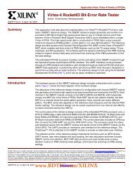
Displaying alphanumeric characters on <strong>the</strong> <strong>LCD</strong> glassAN31144.4 Connecting <strong>the</strong> cus<strong>to</strong>m <strong>LCD</strong> glass HXO5002B <strong>to</strong> <strong>the</strong> <strong>LCD</strong>controlleravailable in medium+ density <strong>STM8L152x</strong> <strong>and</strong> high density<strong>STM8L152x</strong>/<strong>STM8L162x</strong> density devicesTo display an alphanumeric character on <strong>the</strong> cus<strong>to</strong>m <strong>LCD</strong> glass display HXO5002Bavailable in medium+ density <strong>STM8L152x</strong> <strong>and</strong> high density <strong>STM8L152x</strong>/<strong>STM8L162x</strong>density devices, six common lines (COM) <strong>and</strong> three segment lines (SEG) are required. Theselected COM from <strong>the</strong> eight available COM in medium+ <strong>and</strong> high density<strong>STM8L152x</strong>/<strong>STM8L162x</strong> devices <strong>use</strong>d on <strong>the</strong> STM8L1528-EVAL are COM0, COM1,COM4, COM5, COM6 <strong>and</strong> COM7. Table 3 shows <strong>the</strong> correspondence between <strong>the</strong> <strong>LCD</strong>controller available in medium+ density <strong>STM8L152x</strong> devices <strong>and</strong> high density<strong>STM8L152x</strong>/<strong>STM8L162x</strong> device segment lines, <strong>the</strong> <strong>LCD</strong> segment in <strong>the</strong> <strong>LCD</strong> RAM <strong>and</strong> <strong>the</strong>reference letter for each alphanumeric character on <strong>the</strong> <strong>LCD</strong> glass.Table 3.Reference letter for an alphanumeric character on cus<strong>to</strong>m <strong>LCD</strong>HXO5002BCouple (COM/SEG)<strong>LCD</strong> segment in <strong>LCD</strong> RAMReference letter for analphanumeric characterCOM0/SEG(n) <strong>LCD</strong> segment(n) -COM0/SEG(n+1) <strong>LCD</strong> segment(n+1) DCOM0/SEG(n+2) <strong>LCD</strong> segment(n+2) QCOM1/SEG(n) <strong>LCD</strong> segment(n+40) -COM1/SEG(n+1) <strong>LCD</strong> segment(n+1+40) KCOM1/SEG(n+2) <strong>LCD</strong> segment(n+2+40) LCOM4/SEG(n) <strong>LCD</strong> segment(n) ICOM4/SEG(n+1) <strong>LCD</strong> segment(n+1) ACOM4/SEG(n+2) <strong>LCD</strong> segment(n+2) GCOM5/SEG(n) <strong>LCD</strong> segment(n+40) BCOM5/SEG(n+1) <strong>LCD</strong> segment(n+1+40) HCOM5/SEG(n+2) <strong>LCD</strong> segment(n+2+40) FCOM6/SEG(n) <strong>LCD</strong> segment(n+80) CCOM6/SEG(n+1) <strong>LCD</strong> segment(n+1+80) MCOM6/SEG(n+2) <strong>LCD</strong> segment(n+2+80) PCOM7/SEG(n) <strong>LCD</strong> segment(n+120) JCOM7/SEG(n+1) <strong>LCD</strong> segment(n+1+120) NCOM7/SEG(n+2) <strong>LCD</strong> segment(n+2+120) ENote: 1 “n” values can be (25, 28, 33, 36, 39 <strong>and</strong> 42) respectively for alphanumeric characternumbers (7, 6, 4, 3, 2 <strong>and</strong> 1).2 This reference table covers all alphanumeric character, except <strong>the</strong> alphanumeric characternumber 5 that is managed by <strong>the</strong> segment (24, 31 <strong>and</strong> 32).30/43 Doc ID 16829 Rev 2www.BDTIC.com/ST
AN3114Displaying alphanumeric characters on <strong>the</strong> <strong>LCD</strong> glassIn medium+ <strong>and</strong> high density <strong>STM8L152x</strong>/<strong>STM8L162x</strong> devices, <strong>the</strong> <strong>LCD</strong> RAM is accessedthrough two pages, each activated by <strong>the</strong> PAGE_COM bit in <strong>the</strong> <strong>LCD</strong>_CR4 register:– When PAGE_COM = 0: <strong>the</strong> <strong>LCD</strong> RAM register address gives access <strong>to</strong> <strong>the</strong> first<strong>LCD</strong> RAM page, selecting COM0, 1, 2 <strong>and</strong> 3.– When PAGE_COM = 1: <strong>the</strong> <strong>LCD</strong> RAM register address gives access <strong>to</strong> <strong>the</strong>second <strong>LCD</strong> RAM page, selecting COM4, 5, 6 <strong>and</strong> 7.The <strong>LCD</strong> segments are individually controlled by selecting <strong>the</strong> dedicated page <strong>and</strong> setting orclearing <strong>the</strong> corresponding bit of <strong>the</strong> <strong>LCD</strong> data registers (<strong>LCD</strong>_RAM[21:0]).The <strong>LCD</strong> controller module h<strong>and</strong>les <strong>the</strong> encoding of <strong>the</strong> physical drive waveforms <strong>to</strong> <strong>the</strong>cus<strong>to</strong>m <strong>LCD</strong> Glass HXO5002B.The physical connections between cus<strong>to</strong>m <strong>LCD</strong> HXO5200B <strong>and</strong> <strong>the</strong> <strong>LCD</strong> controlleravailable on <strong>the</strong> medium+ density <strong>STM8L152x</strong> devices <strong>and</strong> on high density<strong>STM8L152x</strong>/<strong>STM8L162x</strong> devices must be performed as shown in Figure 22.Figure 22.HXO5002B <strong>LCD</strong> daughterboardThe physical connections between each pixel, <strong>the</strong> segment lines <strong>and</strong> <strong>the</strong> common linesmust be performed as shown in Table 4.Doc ID 16829 Rev 2 31/43www.BDTIC.com/ST
Displaying alphanumeric characters on <strong>the</strong> <strong>LCD</strong> glassAN3114Table 4.Cus<strong>to</strong>m <strong>LCD</strong> HXO5002B physical mapping32/43 Doc ID 16829 Rev 2www.BDTIC.com/ST
AN3114Displaying alphanumeric characters on <strong>the</strong> <strong>LCD</strong> glassTable 5.The following Table 5 summarizes <strong>the</strong> correspondence between <strong>LCD</strong>_RAM register bits <strong>and</strong>each <strong>LCD</strong> character in <strong>the</strong> cus<strong>to</strong>m <strong>LCD</strong> glass HXO5200B.<strong>LCD</strong>_RAM bits versus cus<strong>to</strong>m <strong>LCD</strong> HXO5002B characters<strong>LCD</strong> RAM Bit7 Bit6 Bit5 Bit4 Bit3 Bit2 Bit1 Bit0First page (PAGE_COM bit = 0)<strong>LCD</strong>_RAM0 7D S Q5 6D O4 Q4 5D O1<strong>LCD</strong>_RAM1 C4 Q1 2D C1 - 1D S5 Q6<strong>LCD</strong>_RAM2 3e 2e 1e Q3 4D uA Q2 3D<strong>LCD</strong>_RAM3 O3 5L 5K O2 7e 6e 5e 4e<strong>LCD</strong>_RAM4 1L 1K S6 7L 7K nA 6L 6K<strong>LCD</strong>_RAM5 4K mA 3L 3K C3 2L 2K C2<strong>LCD</strong>_RAM6 7f 6f 5f 4f 3f 2f 1f 4L<strong>LCD</strong>_RAM7 18b 19b 14b 15b 16b 11b 12b 13b<strong>LCD</strong>_RAM8 7b 2b 3b 4b S2 S4 1b 17b<strong>LCD</strong>_RAM9 3c 2c 1c 8b 9b 10b 5b 6b<strong>LCD</strong>_RAM10 16a 11a 12a 13a 7c 6c 5c 4c<strong>LCD</strong>_RAM11 S1 S3 1a 17a 18a 19a 14a 15a<strong>LCD</strong>_RAM12 9a 10a 5a 6a 7a 2a 3a 4a<strong>LCD</strong>_RAM13 7d 6d 5d 4d 3d 2d 1d 8a<strong>LCD</strong>_RAM14 15e 14e 13e 12e 11e 10e 9e 8e<strong>LCD</strong>_RAM15 19e 18e 17e 16e<strong>LCD</strong>_RAM16 15f 14f 13f 12f 11f 10f 9f 8f<strong>LCD</strong>_RAM17 19f 18f 17f 16f<strong>LCD</strong>_RAM18 15c 14c 13c 12c 11c 10c 9c 8c<strong>LCD</strong>_RAM19 19c 18c 17c 16c<strong>LCD</strong>_RAM20 15d 14d 13d 12d 11d 10d 9d 8d<strong>LCD</strong>_RAM21 19d 18d 17d 16dColor key for first page:= Pixels connected <strong>to</strong> COM0 (M[i][0])= Pixels connected <strong>to</strong> COM1 (M[i][1])= Pixels connected <strong>to</strong> COM2 (M[i][2])= Pixels connected <strong>to</strong> COM3 (M[i][3])Doc ID 16829 Rev 2 33/43www.BDTIC.com/ST
Displaying alphanumeric characters on <strong>the</strong> <strong>LCD</strong> glassAN3114Table 5. <strong>LCD</strong>_RAM bits versus cus<strong>to</strong>m <strong>LCD</strong> HXO5002B characters (continued)Second page (PAGE_COM bit = 1)<strong>LCD</strong>_RAM0 7A 7I 6G 6A 6I 5G 5A 5I<strong>LCD</strong>_RAM1 3I 2G 2A 2I 1G 1A 1I 7G<strong>LCD</strong>_RAM2 3j 2j 1j 4G 4A 4I 3G 3A<strong>LCD</strong>_RAM3 6B 5F 5H 5B 7j 6j 5j 4j<strong>LCD</strong>_RAM4 1F 1H 1B 7F 7H 7B 6F 6H<strong>LCD</strong>_RAM5 4H 4B 3F 3H 3B 2F 2H 2B<strong>LCD</strong>_RAM6 7i 6i 5i 4i 3i 2i 1i 4F<strong>LCD</strong>_RAM7 7M 7C 5P 6M 6C 4P 5M 5C<strong>LCD</strong>_RAM8 3C 1P 2M 2C + 1M 1C 6P<strong>LCD</strong>_RAM9 3h 2h 1h 3P 4M 4C 2P 3M<strong>LCD</strong>_RAM10 6J 5E 5N 5J 7h 6h 5h 4h<strong>LCD</strong>_RAM11 1E 1N 1J 7E 7N 7J 6E 6N<strong>LCD</strong>_RAM12 4N 4J 3E 3N 3J 2E 2N 2J<strong>LCD</strong>_RAM13 7g 6g 5g 4g 3g 2g 1g 4E<strong>LCD</strong>_RAM14 15j 14j 13j 12j 11j 10j 9j 8j<strong>LCD</strong>_RAM15 19j 18j 17j 16j<strong>LCD</strong>_RAM16 15i 14i 13i 12i 11i 10i 9i 8i<strong>LCD</strong>_RAM17 19i 18i 17i 16i<strong>LCD</strong>_RAM18 15h 14h 13h 12h 11h 10h 9h 8h<strong>LCD</strong>_RAM19 19h 18h 17h 16h<strong>LCD</strong>_RAM20 15g 14g 13g 12g 11g 10g 9g 8g<strong>LCD</strong>_RAM21 19g 18g 17g 16gColor key for second page:= Pixels connected <strong>to</strong> COM4 (M[i][4])= Pixels connected <strong>to</strong> COM5 (M[i][5])= Pixels connected <strong>to</strong> COM6 (M[i][6])= Pixels connected <strong>to</strong> COM7 (M[i][7])34/43 Doc ID 16829 Rev 2www.BDTIC.com/ST
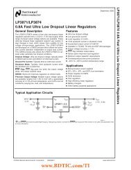
AN3114Displaying alphanumeric characters on <strong>the</strong> <strong>LCD</strong> glassTo be able <strong>to</strong> make an efficient <strong>LCD</strong> software driver <strong>and</strong> optimize <strong>the</strong> <strong>LCD</strong> character codingin terms of code density, <strong>the</strong> matrix shown in Figure 23 has been chosen.Figure 23.HXO5002B segment driver matrixEach matrix M element corresponds <strong>to</strong> one bit on <strong>the</strong> <strong>LCD</strong>_RAM[13:0] registers. To enableSEG(i) connected <strong>to</strong> COM(j), <strong>the</strong> “M[i][j]” element must be set <strong>to</strong> 1 <strong>and</strong> <strong>to</strong> disable it <strong>the</strong>“M[i][j]” element must be set <strong>to</strong> 0.The following structure provided in <strong>the</strong> <strong>LCD</strong> firmware enables <strong>to</strong> translate alphanumericcharacters from ASCII in<strong>to</strong> <strong>LCD</strong>_RAM[21:0]:bit[17:0] = Nibble[5:0] = {<strong>LCD</strong>_RAM[13:10], <strong>LCD</strong>_RAM[10:7],<strong>LCD</strong>_RAM[6:3], <strong>LCD</strong>_RAM[3:0],<strong>LCD</strong>_RAM[10:7], <strong>LCD</strong>_RAM[13:10]};bit[17:0] are <strong>the</strong> 18 matrix terms arranged so that each nibble is related <strong>to</strong> <strong>LCD</strong>_RAMregister <strong>and</strong> <strong>to</strong> COMi in <strong>the</strong> selected page. The relation between <strong>the</strong> nibbles <strong>and</strong> <strong>the</strong><strong>LCD</strong>_RAM registers is conditioned by <strong>the</strong> <strong>LCD</strong> digit being accessed. Refer <strong>to</strong> Table 5 for <strong>the</strong>correspondence between <strong>LCD</strong>_RAM register bits (nibble) <strong>and</strong> <strong>LCD</strong> character.Displaying a character “A” on <strong>the</strong> cus<strong>to</strong>m <strong>LCD</strong> glass HXO5002BThe <strong>LCD</strong> segments A, B, C, E, F, M <strong>and</strong> N must be activated <strong>to</strong> display <strong>the</strong> “A” letter (seeFigure 24). These segments must <strong>the</strong>n be transferred from <strong>the</strong> <strong>LCD</strong>_RAM registers <strong>to</strong> <strong>the</strong><strong>LCD</strong> glass. Use <strong>the</strong> matrix described in Figure 23 <strong>to</strong> know which bits of <strong>the</strong> <strong>LCD</strong>_RAMregisters must be set.The firmware structure provides <strong>the</strong> value 0x002536 for Nibble[5:0] corresponding <strong>to</strong>:● Nibble[0] = 0x0 = 000b● Nibble[1] = 0x0 = 000b● Nibble[2] = 0x2 = 010b● Nibble[3] = 0x5 = 101b● Nibble[4] = 0x3 = 011b● Nibble[5] = 0x6 = 110bDoc ID 16829 Rev 2 35/43www.BDTIC.com/ST
Displaying alphanumeric characters on <strong>the</strong> <strong>LCD</strong> glassAN3114Note:To display “A” on position five on <strong>the</strong> <strong>LCD</strong> glass, <strong>the</strong> <strong>LCD</strong>_RAM registers must beprogrammed as follows:● Nibble[0] in <strong>LCD</strong>_RAM0[0:2] bits: page0 COM0● Nibble[1] in <strong>LCD</strong>_RAM3[4:6] bits: page0 COM1● Nibble[2] in <strong>LCD</strong>_RAM0[0:2] bits: page1 COM4● Nibble[3] in <strong>LCD</strong>_RAM3[4:6] bits: page1 COM5● Nibble[4] in <strong>LCD</strong>_RAM7[0:2] bits: page1 COM6● Nibble[5] in <strong>LCD</strong>_RAM10[4:6] bits: page1 COM7All upper case letters <strong>and</strong> numbers are converted from ASCII characters <strong>to</strong> <strong>LCD</strong>_RAMregister format. The <strong>LCD</strong> letter <strong>and</strong> number maps are s<strong>to</strong>red in two Flash tables (LetterMap<strong>and</strong> NumberMap) as constants which are <strong>use</strong>d when translating <strong>the</strong> ASCII characters <strong>to</strong><strong>LCD</strong> RAM registers. For more details, refer <strong>to</strong> stm8l1528_eval_glass_lcd.c driver.Figure 24.Letter “A” displayed on <strong>the</strong> cus<strong>to</strong>m <strong>LCD</strong> HXO5002BFigure 25.Displaying “A” on <strong>the</strong> matrix for <strong>the</strong> cus<strong>to</strong>m <strong>LCD</strong> HXO5002B36/43 Doc ID 16829 Rev 2www.BDTIC.com/ST
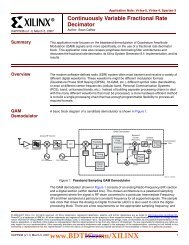
AN3114<strong>LCD</strong> segment drive firmware5 <strong>LCD</strong> segment drive firmwareTo facilitate <strong>the</strong> development of cus<strong>to</strong>mer applications, ST provides a firmware <strong>to</strong> drive <strong>the</strong><strong>LCD</strong> segments.This firmware runs on <strong>the</strong> STM8L1526-EVAL <strong>and</strong> STM8L1528-EVAL evaluation boards,which provide all <strong>the</strong> hardware features <strong>to</strong> interface with an <strong>LCD</strong> glass.● STM8L1528-EVAL set-up– Make sure that <strong>the</strong> <strong>LCD</strong> glass daughterboard (MB905) is mounted in <strong>LCD</strong>position.● STM8L1526-EVAL set-up– JP7 jumper on <strong>the</strong> Key position– Make sure that <strong>the</strong> <strong>LCD</strong> glass daughterboard (MB821) is mounted in <strong>LCD</strong>position.For more details, please refer <strong>to</strong> <strong>the</strong> evaluation board <strong>use</strong>r manuals.5.1 Firmware package descriptionThe <strong>LCD</strong> segment drive firmware package contains both projects, one running onSTM8L1528-EVAL <strong>and</strong> <strong>the</strong> o<strong>the</strong>r on STM8L1526-EVAL, <strong>and</strong> each project provides <strong>the</strong> <strong>LCD</strong>glass library <strong>and</strong> <strong>the</strong> firmware described in this section.The firmware package contains <strong>the</strong> following direc<strong>to</strong>ries (see Figure 26):● Libraries direc<strong>to</strong>ry● Project direc<strong>to</strong>ry● Utilities direc<strong>to</strong>ryFigure 26.<strong>LCD</strong> segment drive firmware structureDoc ID 16829 Rev 2 37/43www.BDTIC.com/ST
<strong>LCD</strong> segment drive firmwareAN31145.1.1 Libraries direc<strong>to</strong>ryThe Libraries direc<strong>to</strong>ry contains <strong>the</strong> subdirec<strong>to</strong>ries <strong>and</strong> files that make up <strong>the</strong> core of <strong>the</strong><strong>LCD</strong> segment drive firmware:●●inc subdirec<strong>to</strong>ry contains <strong>the</strong> firmware library header files.src subdirec<strong>to</strong>ry contains <strong>the</strong> firmware library source files.5.1.2 Projects direc<strong>to</strong>ryThe Projects direc<strong>to</strong>ry includes <strong>the</strong> <strong>LCD</strong>_SegmentsDrive subdirec<strong>to</strong>ry, which contains <strong>the</strong>subdirec<strong>to</strong>ries <strong>and</strong> files that make up <strong>the</strong> core of <strong>the</strong> <strong>LCD</strong> glass interface applicationexample:● inc subdirec<strong>to</strong>ry contains <strong>the</strong> example header files.● src subdirec<strong>to</strong>ry contains <strong>the</strong> example source files.● project subdirec<strong>to</strong>ry contains <strong>the</strong> projects <strong>use</strong>d <strong>to</strong> compile <strong>the</strong> firmware files.5.1.3 Utilities direc<strong>to</strong>ryThe Utilities direc<strong>to</strong>ry contains <strong>the</strong> subdirec<strong>to</strong>ries <strong>and</strong> files <strong>use</strong>d <strong>to</strong> control <strong>the</strong> STM8L1526-EVAL <strong>and</strong> STM8L1528-EVAL board hardware.5.2 Firmware descriptionThe real-time clock (RTC) provides a set of continuously running counters that can be <strong>use</strong>d<strong>to</strong> implement a clock-calendar function. The counters values can be written <strong>to</strong> set <strong>the</strong>current time of <strong>the</strong> system. After <strong>the</strong> evaluation board is powered up, <strong>the</strong> default time(00:00:00) is displayed on <strong>the</strong> <strong>LCD</strong> glass <strong>and</strong> <strong>the</strong> first digit of <strong>the</strong> hour field can be changed.Note:To set <strong>the</strong> time:1. Press <strong>the</strong> Key but<strong>to</strong>n <strong>to</strong> increment <strong>the</strong> active digit. When <strong>the</strong> Key but<strong>to</strong>n is released <strong>the</strong>selected value is s<strong>to</strong>red <strong>and</strong> <strong>the</strong> next digit can be changed. The digit allowed valuesdepend on <strong>the</strong> corresponding field (hour, minute or seconds).2. Repeat <strong>the</strong>se two steps for <strong>the</strong> six digits.Once all <strong>the</strong> digits are set, <strong>the</strong> RTC calendar registers are configured, <strong>and</strong> <strong>the</strong> current timeis displayed on <strong>the</strong> <strong>LCD</strong>. The application enters Active-halt mode <strong>and</strong> is woken up by <strong>the</strong>RTC wakeup interrupt <strong>to</strong> display <strong>the</strong> current time. It <strong>the</strong>n goes back <strong>to</strong> <strong>the</strong> Active-halt mode.This operation is repeated infinitely.Time setting is made only once after <strong>the</strong> application startup. The application must berestarted <strong>to</strong> modify <strong>the</strong> time.38/43 Doc ID 16829 Rev 2www.BDTIC.com/ST
<strong>LCD</strong> segment drive firmwareAN31145.2.1 <strong>LCD</strong> controller setupThe following steps are recommended <strong>to</strong> configure <strong>the</strong> <strong>LCD</strong> controller:1. Enable <strong>the</strong> <strong>LCD</strong> clock.2. Configure <strong>the</strong> RTC clock source.3. Configure <strong>the</strong> duty ratio <strong>and</strong> <strong>the</strong> bias.4. Configure <strong>the</strong> frame frequency in <strong>the</strong> operating frequency range of <strong>the</strong> <strong>LCD</strong> glass, thatis between 20 <strong>and</strong> 85 Hz.5. Configure <strong>the</strong> voltage source.6. Configure <strong>the</strong> port mask registers according <strong>to</strong> <strong>the</strong> pins <strong>use</strong>d as segment lines.7. If <strong>the</strong> internal voltage source is selected, <strong>the</strong>n adjust <strong>the</strong> contrast using <strong>the</strong> contrastbits.8. If <strong>the</strong> external voltage source is selected, <strong>the</strong>n adjust <strong>the</strong> contrast using <strong>the</strong> dead timebits.9. The contrast can be adjusted also using <strong>the</strong> pulse on duration bits.10. Enable <strong>the</strong> <strong>LCD</strong> controller.In this application, <strong>the</strong> <strong>LCD</strong> controller is configured as follows:● <strong>LCD</strong> clock source frequencyf <strong>LCD</strong>CLK = LSE frequency = 32.768 KHz● Prescaler fac<strong>to</strong>r = 2● Divider fac<strong>to</strong>r = 18 (16 + 2)● Mode = 1/4 Duty, 1/3 Bias applies <strong>to</strong> medium density <strong>STM8L152x</strong> devices (PD-878<strong>LCD</strong> Glass) <strong>and</strong> Mode = 1/8 Duty, 1/4 Bias applies <strong>to</strong> high density<strong>STM8L152x</strong>/<strong>STM8L162x</strong> devices (HXO5002B cus<strong>to</strong>m <strong>LCD</strong> glass)● <strong>LCD</strong> clock frequencyThe <strong>LCD</strong> clock frequency, f frame , is given by <strong>the</strong> equation below:f frame= f ck_divxduty =f <strong>LCD</strong>CLK-----------------------------------------2 PS xdutyx16 ( + DIV)As a result, if f ck_div equals 228 Hz, f frame = 57Hz for PD-878 <strong>LCD</strong> glass <strong>and</strong> f frame =28.5 Hz for cus<strong>to</strong>m <strong>LCD</strong> glass HXO5002B.40/43 Doc ID 16829 Rev 2www.BDTIC.com/ST
AN3114Conclusion6 ConclusionThe <strong>LCD</strong> segment drive firmware allows <strong>to</strong> develop an <strong>LCD</strong> glass based application with <strong>the</strong>minimum firmware <strong>and</strong> hardware resources.Doc ID 16829 Rev 2 41/43www.BDTIC.com/ST
Revision his<strong>to</strong>ryAN31147 Revision his<strong>to</strong>ryTable 6. Document revision his<strong>to</strong>ryDate Revision Changes22-Jan-2010 1 Initial release.02-Aug-2011 2Added:– Support for <strong>the</strong> medium+ <strong>and</strong> high density<strong>STM8L152x</strong>/<strong>STM8L162x</strong> devices– <strong>How</strong> <strong>to</strong> <strong>use</strong> <strong>the</strong> cus<strong>to</strong>m <strong>LCD</strong> HXO5002B available on STM8L1528-EVAL– Section 1.1: Definitions– Discrimination ratio calculationUpdated:– All data regarding generation of <strong>LCD</strong> voltage42/43 Doc ID 16829 Rev 2www.BDTIC.com/ST
AN3114Please Read Carefully:Information in this document is provided solely in connection with ST products. STMicroelectronics NV <strong>and</strong> its subsidiaries (“ST”) reserve <strong>the</strong>right <strong>to</strong> make changes, corrections, modifications or improvements, <strong>to</strong> this document, <strong>and</strong> <strong>the</strong> products <strong>and</strong> services described herein at anytime, without notice.All ST products are sold pursuant <strong>to</strong> ST’s terms <strong>and</strong> conditions of sale.Purchasers are solely responsible for <strong>the</strong> choice, selection <strong>and</strong> <strong>use</strong> of <strong>the</strong> ST products <strong>and</strong> services described herein, <strong>and</strong> ST assumes noliability whatsoever relating <strong>to</strong> <strong>the</strong> choice, selection or <strong>use</strong> of <strong>the</strong> ST products <strong>and</strong> services described herein.No license, express or implied, by es<strong>to</strong>ppel or o<strong>the</strong>rwise, <strong>to</strong> any intellectual property rights is granted under this document. If any part of thisdocument refers <strong>to</strong> any third party products or services it shall not be deemed a license grant by ST for <strong>the</strong> <strong>use</strong> of such third party productsor services, or any intellectual property contained <strong>the</strong>rein or considered as a warranty covering <strong>the</strong> <strong>use</strong> in any manner whatsoever of suchthird party products or services or any intellectual property contained <strong>the</strong>rein.UNLESS OTHERWISE SET FORTH IN ST’S TERMS AND CONDITIONS OF SALE ST DISCLAIMS ANY EXPRESS OR IMPLIEDWARRANTY WITH RESPECT TO THE USE AND/OR SALE OF ST PRODUCTS INCLUDING WITHOUT LIMITATION IMPLIEDWARRANTIES OF MERCHANTABILITY, FITNESS FOR A PARTICULAR PURPOSE (AND THEIR EQUIVALENTS UNDER THE LAWSOF ANY JURISDICTION), OR INFRINGEMENT OF ANY PATENT, COPYRIGHT OR OTHER INTELLECTUAL PROPERTY RIGHT.UNLESS EXPRESSLY APPROVED IN WRITING BY TWO AUTHORIZED ST REPRESENTATIVES, ST PRODUCTS ARE NOTRECOMMENDED, AUTHORIZED OR WARRANTED FOR USE IN MILITARY, AIR CRAFT, SPACE, LIFE SAVING, OR LIFE SUSTAININGAPPLICATIONS, NOR IN PRODUCTS OR SYSTEMS WHERE FAILURE OR MALFUNCTION MAY RESULT IN PERSONAL INJURY,DEATH, OR SEVERE PROPERTY OR ENVIRONMENTAL DAMAGE. ST PRODUCTS WHICH ARE NOT SPECIFIED AS "AUTOMOTIVEGRADE" MAY ONLY BE USED IN AUTOMOTIVE APPLICATIONS AT USER’S OWN RISK.Resale of ST products with provisions different from <strong>the</strong> statements <strong>and</strong>/or technical features set forth in this document shall immediately voidany warranty granted by ST for <strong>the</strong> ST product or service described herein <strong>and</strong> shall not create or extend in any manner whatsoever, anyliability of ST.ST <strong>and</strong> <strong>the</strong> ST logo are trademarks or registered trademarks of ST in various countries.Information in this document supersedes <strong>and</strong> replaces all information previously supplied.The ST logo is a registered trademark of STMicroelectronics. All o<strong>the</strong>r names are <strong>the</strong> property of <strong>the</strong>ir respective owners.© 2011 STMicroelectronics - All rights reservedSTMicroelectronics group of companiesAustralia - Belgium - Brazil - Canada - China - Czech Republic - Finl<strong>and</strong> - France - Germany - Hong Kong - India - Israel - Italy - Japan -Malaysia - Malta - Morocco - Philippines - Singapore - Spain - Sweden - Switzerl<strong>and</strong> - United Kingdom - United States of Americawww.st.comDoc ID 16829 Rev 2 43/43www.BDTIC.com/ST