manual plastic strapping tool model p404 - Acme Packaging
manual plastic strapping tool model p404 - Acme Packaging
manual plastic strapping tool model p404 - Acme Packaging
- No tags were found...

You also want an ePaper? Increase the reach of your titles
YUMPU automatically turns print PDFs into web optimized ePapers that Google loves.
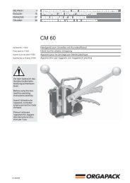
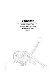
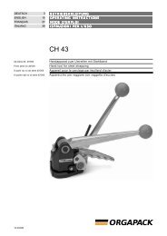
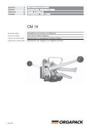
OPERATION MANUAL / SPARE PARTS LISTMANUAL PLASTIC STRAPPING TOOLMODEL P40443.0404.0243040402.en/MAS/© 12.05
INDEXPAGE1 SAFETY INSTRUCTIONS 22 TECHNICAL DATA 33 OPERATION ELEMENTS 44 ADJUSTMENT OF THE STRAP THICKNESS 55 OPERATION 56 SPARE PARTS LIST 43.0404.02 107 EXCHANGE OF WEARING PARTS 127.1 Exchange of the cutter . . . . . . . . . . . . . . . . . . . . 127.2 Exchange of gripper and gripping jaw . . . . . . . . 138 WARRANTY CONDITIONS AND LIABILITY 149 APPROPRIATE USE 141 SAFETY INSTRUCTIONSRead these instructions carefully. Failure to follow these instructions can result in severe personal injury.Eye injury hazardFailure to wear safety glasses with side shields can result in severe eye injury or blindness.Always wear safety glasses with side shields which conform to ANSI Standard Z87.1.OperationTool must not be used by persons not properly trained in their use. Before tensioning strap, read andunderstand the <strong>tool</strong> operating instructions. Failure to follow the operating instructions or improperloadpositioning could result in strap breakage.Become familiar with your <strong>tool</strong> and keep fingers away from areas that can pinch or cut.Cutting tensioned strapWhen cutting <strong>strapping</strong>, use the proper <strong>strapping</strong> cutter and keep other personnel and yourself at a safedistance from the strap. Always stand to side of the strap, away from the direction the loosened strap end willfly. Use only cutters designed for strap and never hammers, pliers, hacksaws, axes, etc.2
JointsYou are fully responsible to review the joints made by your <strong>tool</strong>. Become familiar with the seal control and sealadjustment described in this operation <strong>manual</strong>.Misformed joints may not secure the load and could cause serious injury. Never handle or ship any load withimproperly formed joints.Dispensing strapOnly dispense strap from a dispenser specifically designed for strap.Tuck strap end back into dispenser when not in use.Strap warningsNever use strap as a means of pulling or lifting loads. Failure to follow these warnings can result in severepersonal injury.Strap breakage hazardImproper operation of the <strong>tool</strong>, excessive tensioning, using strap not recommended for this <strong>tool</strong> or sharpcorners on the load can result in a sudden loss of strap tension or in strap breakage during tensioning, whichcould result in the following:• A sudden loss of balance causing you to fall.• Both <strong>tool</strong> and strap flying violently towards your face.Note as follows:• If the load corners are sharp, use edge protectors.• Place the strap correctly around a properly positioned load.• Positioning yourself in-line with the strap, during tensioning and sealing, can result in severe personalinjury from flying strap or <strong>tool</strong>. When tensioning or sealing, position yourself to one side of the strap andkeep all bystanders away.• Use the correct strap quality, strap width, strap gauge and strap tensile strength recommended in this<strong>manual</strong> for your <strong>tool</strong>. Using strap not recommended for this <strong>tool</strong> can result in strap breakage duringtensioning.Fall hazardMaintaining improper footing and/or balance when operating the <strong>tool</strong> can cause you to fall. Before tensioningand especially in elevated areas, always establish good balance. Both feet should be securely placed on aflat, solid surface, especially when working in elevated areas. Do not use the <strong>tool</strong> when you are in an awkwardposition.Tool hazardsA well maintained <strong>tool</strong> is a safe <strong>tool</strong>!Check <strong>tool</strong> regularly for broken or worn parts. Do not operate a <strong>tool</strong> with broken or worn parts.Never modify any <strong>tool</strong>. Modification can result in severe bodily injury.2 TECHNICAL DATADimensionsLength: 376 mm / 14.8"Width: 128 mm / 5"Height: 244 mm / 9.6"WeightTool :3.8 Kg / 8.4 lbsStrap DimensionsWidths: 15 - 16 mm / 0.59 - 0.63"Thicknesses: 0.5 - 0.9 mm / 0.020 - 0.035"3
Strap QualitiesPolypropylene, plain or embossedPolyester, plain or embossedSealsP404 / 16 MM Item No.: 41.5082Joint strengthDepending on the strap quality the joint strength varies between 40 to 80 % of the breaking strength of thestrap.Using low gauge straps, the joint strength is relatively high whereas high gauge straps tend to have a lowerjoint strength.Tension forceThe tension force is calculated by the applied <strong>manual</strong> force multiplied by 10.Thus the tension force is 200 N x 10= 2‘000 N if the applied <strong>manual</strong> force is 200 N at the tension lever.When applying tension, the tension force must not exceed the breaking strength of the seal joint.3 OPERATION ELEMENTSTension handleSealing leverTensioning drumGripping jawLifting handle4
ATTENTION! Before starting using the <strong>tool</strong> it has to be adjustedto the strap thickness used!4 ADJUSTMENT OF THE STRAP THICKNESSIn order to achieve the highest possibleseal efficiency the <strong>tool</strong> must be adjusted tothe respective strap thickness through theuse of the parallel pin N2.2185 and thestop P40.2511. Please proceed as follows:- remove the side plate- bring the parallel pin N2.2185 and ifnecessary the stop P40.2511 intothe correct position of the strapthickness used- reattach the side plate- in order to avoid the strap slippingbetween gripper and gripping jawthe shims underneath the grippingjaw have to be assembled accordingto below table.Pos. 2 P40.2511Pos. 1N2.2185N1.6504N1.1910StrapthicknessStopShim*0.50 - 0.59 mm N2.2185 in Pos. 1 2 x P40.20520.60 - 0.74 mm N2.2185 in Pos. 2 1 x P40.20520.75 - 0.90 mm N2.2185 andP40.2511 in Pos. 20* See 7.2 changing of gripper and gripping jaw.5 OPERATIONIntroducing the sealThe seal is introduced into the <strong>tool</strong> from the rear sideuntil it hits the strap stop. Use the left hand.Feeding the <strong>strapping</strong> around the packageThe <strong>plastic</strong> <strong>strapping</strong> is fed around the package asshown in the illustration.5
Inserting the lower strapThe lifting handle is raised with the right hand. Thelower strap is inserted into the seal and the stopbehind the gripper respectively. The strap end shouldslightly protrude the seal.By lowering the lifting handle the strap is clamped inits position.Inserting the upper strapThe <strong>tool</strong> is held with the right hand. The left handinserts the upper strap into the seal, through bothcutters and into the tensioning drum.Notice: the strap may be inserted into the <strong>tool</strong> in thebest possible way if the tensioning drum has beenbrought into the position shown.Tensioning of the <strong>plastic</strong> strapBy operating the tension handle, the strap istensioned to the desired amount of tension.Sealing the <strong>strapping</strong>The seal is closed by a forward movement to thestop of the sealing lever.6
Cutting off of the <strong>plastic</strong> strapBy raising the lifting handle the gripper is releasedand the <strong>plastic</strong> strap is cut off.Removing the <strong>tool</strong>Remove the <strong>tool</strong> from the strap to the right withthe lifting handle in a raised position.Straightening the <strong>plastic</strong> strapRemove the strap from the tensioning drum andstraighten the strap bent by the winding of thetensioning drum.Operation of the <strong>tool</strong> with a horizontalhandleUpon request the <strong>tool</strong> can be provided with ahorizontal handle P40.2046 consisting of a plugP40.2047 and the grip ball N4.1118.After the removal of the protection plug N4.5120the horizontal handle can be screwed into thebody.7
A1 2 3N2.1128N2.2441P40.2018P40.2017BP40.2513➂ N11.1154N2.1122N2.5211A43.1207 ➀N3.3150CP40.2517N7.1207N1.6226➀ N3.3148P40.0101➀ P40.2504N2.1609➀ P40.2516N1.3511P40.2501➀ N2.5234P40.2511P40.2515DN2.5820 ➀ N3.3171N2.2185P40.2523N2.4902P40.0102P40.2503➀ N3.3171N3.3167N1.2104➀ N2.5614➀ P40.2510P40.2505 ➃P40.2506 ➃➀ P40.2526E➀ P40.2509➀ N2.5212P40.2012 ➀P40.0104P40.2529➀ P40.2507N2.2447N2.2816N2.2441N1.1125P40.2508N1.116243040402.z
4 5 6 7P40.2514N4.1116P40.0103N1.3106N1.5131P40.2518P40.2030N1.3508P40.2528A33.3111 ➀N2.5154 ➀➀ N3.3113P40.2029P40.2004N2.2709N3.3113 ➀A43.1207 ➀N3.2609 ➀P40.2029P40.2025N2.2457N2.2709N2.2185P40.2028N2.5819N3.3151N4.5120P40.2509➀P40.2520N2.2806P40.2024➁ N3.4506➀ P40.2522➀ N3.2609P40.2521P40.2519P40.2525 ➀P40.2512 ➀P40.2053N1.6504P40.2527P40.2524 ➀P40.2052N2.2441N1.6504N41.9110N1.6203N2.4902N1.1125N1.6504N1.1909N1.1910N41.9127 ESSO Beacon 2➁ORIENTATION38 Nm COMPENSATIONP40.2045
6 SPARE PARTS LIST 43.0404.0243.0404.02 P404/15-16/0.50-0.90 P404.0001.02 12.01.00Item-No. in group Pcs. description Dimension FieldA33.3111 2 CATCH PAWL B4A43.1207 2 DISK B4+N11.1154 2 SCREW M10 X 97 B3N1.1125 3 SCREW M6 X 16 E4N1.1162 2 SCREW M3 X 12 E2N1.1909 1 FLAT HEAD SCREW M3 X 5 E5N1.1910 4 FLAT HEAD SCREW M4 X 12 E6N1.2104 1 COUNTERSUNK SCREW M4 X 12 D3N1.3106 1 SOCKET SET SCREW M5 X 6 B5N1.3508 1 SOCKET SET SCREW M5 X 20 B6N1.3511 1 SOCKET SET SCREW M4 X 10 C2N1.5131 1 HEXAGON NUT M5 B6N1.6203 1 SPRING LOCK WASHER M3 E5N1.6226 2 SPRING LOCK WASHER M10 C4N1.6504 5 SAFETY WASHER M4 D5+N2.1122 1 SECURITY RING E21 B4N2.1128 1 SECURITY RING E4 A2N2.1609 1 SPRING RING 10 MM C1N2.2185 2 PARALLEL PIN 6 m6 X 32 C4+N2.2441 4 DOWEL PIN 6 X 20 MM A3+N2.2447 1 DOWEL PIN 2 X 4 MM E2N2.2457 1 DOWEL PIN 5 X 28 C6N2.2709 2 SPLIT PIN 1,6 X 10 MM B5+N2.2806 1 DOWEL PIN 5 X 16 MM C7N2.2816 2 DOWEL PIN 4 X 10 MM E3N2.4902 3 HAMMER HEAD BOLT 1.85 X 4.76 D4+N2.5154 2 PRESSURE SPRING 0.45 X 3.9 X 7 B4N2.5211 1 PRESSURE SPRING 1,2X13X92,7/17.5 B2N2.5212 2 PRESSURE SPRING 0,4X3,6X18,3/14.5 E2N2.5234 1 PRESSURE SPRING 0.56 X 4.25 X 77.50 / C128.5N2.5614 3 CUP SPRING 10X4,2X0,6 D3N2.5819 1 TORSION SPRING 2,2/22,8 C6N2.5820 1 TORSION SPRING 1 / 9 D2N3.2609 P40.0101 2 PACKING RING C5+N3.3113 P40.0103 2 SLIDE-BEARING B5+N3.3148 P40.0101 1 SLIDE-BEARING C3N3.3150 P40.0101 1 SLIDE-BEARING B2N3.3151 P40.0101 2 HEADED PRESS FIT BUSH C6N3.3167 P40.0104 1 SLIDE-BEARING 10 X 12 X 15 D3N3.3171 P40.0101 2 SLIDE-BEARING D4N3.3171 P40.0102 2 SLIDE-BEARING D3N3.4506 P40.0101 1 NEEDLE FREE WHEELING D5N41.9110 1 TYPE PLATE D6N41.9127 1 ADHESIVE LABEL E6N4.1116 2 GRIP BALL A5N4.5120 1 PROTECTION PLUG C4N7.1207 P40.0101 1 SEALING DISK D1=14MM C3[P40.0101] 1 HOUSING C3[P40.0102] 1 PUNCH SUPPORT D2[P40.0103] 1 ROCKER B6[ ] = Group * = Wearing Parts10
43.0404.02 P404/15-16/0.50-0.90 P404.0001.02 12.01.00Item-No. in group Pcs. description Dimension Field[P40.0104] 1 BASE PLATE E3P40.2004 1 TENSION SHAFT B5P40.2012 1 HOLDING-DOWN CLAMP E3P40.2017 1 ROD BAR A2P40.2018 1 BUSH A2P40.2024 1 SHAFT C7P40.2025 1 LEVER C6P40.2028 1 HINGE C5P40.2029 2 SPLIT-PIN BOLT B5+P40.2030 1 SHAFT B5P40.2045 1 SCREW E4P40.2052 2 LINER D5P40.2053 * 1 GRIPPER D5[P40.2501] P40.0101 1 HOUSING C3P40.2503 P40.0102 1 PUNCH SUPPORT D2P40.2504 1 PILLAR C1P40.2505 1 SHIM 0,2 MM D3P40.2506 1 SHIM 0,3 MM D3P40.2507 1 PAWL E2P40.2508 * 1 PUNCH E2P40.2509 2 SHAFT E2+P40.2510 1 PRESSURE ROLLER D1P40.2511 1 STOP C3P40.2512 2 GUIDE GIB D5P40.2513 1 SEALING CAM B3P40.2514 1 SEALING HANDLE A4P40.2515 1 DOWEL C2P40.2516 1 SHAFT C2P40.2517 1 COVER C2P40.2518 1 TENSION HANDLE B4P40.2519 1 SIDE PLATE D5P40.2520 1 CLAMPING LEVER C7P40.2521 * 1 GRIPPING JAW D6P40.2522 1 GRIPPING JAW PIN D6P40.2523 1 STOP D3P40.2524 * 1 SHEAR BLADE D4P40.2525 * 1 SHEAR BLADE D4P40.2526 1 BOLT D3P40.2527 1 TENSIONIG DRUM D6P40.2528 P40.0103 1 ROCKER B6P40.2529 P40.0104 1 BASE PLATE E3[ ] = Group * = Wearing Parts11
7 EXCHANGE OF WEARING PARTS7.1 Exchange of the cutterDisassembly- Remove screw with pivot P40.2045 including safety disk N1.6504.- The lower cutter P40.2524 is lifted against the sealing lever by operating the lifting handle.- Insert a screw driver into the boring of the lower side of the cutter.- Lift out the cutters complete with bolt P40.2526 and the cup springs N2.5614 from the support.Assembly- Assemble the individual components (cutting edges closed).- Press the lifting handle against the sealing lever.- Insert the cutter into the support until it hits the stop.The cutters are correctly positioned if the lower cutter can be moved up and down by lifting andlowering the lifting handle and the screw with pivot can be screwed into the groove of thecutter P40.2525.Adjustment of the cutter- Press the lifting handle against the sealing lever.The blades of the cutters should now overlap by 1 to 2 mm (.040" to .080").- The adjustment is made by the set screw N1.3508 and the counter nut N1.5131 in the lifting handle.P40.2526P40.2524P40.2525N2.5614N1.6504P40.204512
7.2 Exchange of gripper and gripping jaw- Drive out the spirally rolled pin N2.2806 using a split pin driver.- Remove the clamping lever P40.2520 with the pin P40.2522 and the gripping jaw P40.2521.- Screw off and exchange the gripper P40.2053.- Reassemble in the opposite order.*Depending on the strap thickness 2, 1 or no shim P40.2052 must be assembled under the gripping jaw.See 4. adjustment of the strap thickness.Assembly in opposite direction.N2.2806P40.2520P40.2522P40.2521P40.2053P40.2052N1.6203N1.190913
8 WARRANTY CONDITIONS AND LIABILITYFROMM Holding AG warrants all its <strong>strapping</strong> <strong>tool</strong>s and machine heads during a period of 90 days from thedate of sale. The warranty includes all deficiencies clearly resulting from poor manufacturing or faulty materials.Damage claims as a result of production shutdowns and claims for damage to persons and to property resultingfrom warranty deficiencies cannot be asserted by the customer.The warranty excludes:• wearing parts• deficiencies resulting from improper installing, incorrect handling and maintaining the <strong>tool</strong>• deficiencies resulting from using the <strong>tool</strong> without or with defective security- and safety devices• disregard of directions in the operation <strong>manual</strong>• arbitrary modifications of the <strong>tool</strong>• deficient control of wearing parts• deficient repair works of the <strong>tool</strong>• Use of consumable products not recommended by FROMM Holding AGWe reserve the right to modify the product at any time in order to improve its quality.9 APPROPRIATE USEThe <strong>tool</strong> <strong>model</strong> P404 has been designed to strap packages with <strong>plastic</strong> <strong>strapping</strong> exclusively.The warranty / liability excludes:• non appropriate use of the <strong>tool</strong>,• disregard of directions in the operation <strong>manual</strong>,• disregard of control- and maintenance instructions.14