Exergy analysis and flowsheet modification of PT. PUSRI II ...
Exergy analysis and flowsheet modification of PT. PUSRI II ...
Exergy analysis and flowsheet modification of PT. PUSRI II ...
- No tags were found...

You also want an ePaper? Increase the reach of your titles
YUMPU automatically turns print PDFs into web optimized ePapers that Google loves.
ASIA-PACIFIC JOURNAL OF CHEMICAL ENGINEERINGAsia-Pac. J. Chem. Eng. 2011; 6: 760–770Published online 14 March 2011 in Wiley Online Library(wileyonlinelibrary.com) DOI:10.1002/apj.565Special theme research article<strong>Exergy</strong> <strong>analysis</strong> <strong>and</strong> <strong>flowsheet</strong> <strong>modification</strong> <strong>of</strong> <strong>PT</strong>. <strong>PUSRI</strong> <strong>II</strong>Palembang’s reformer unit for the production <strong>of</strong> synthesisgas from natural gasMuhammad Djoni Bustan, 1 * Shuhaimi Mahadzir 2 <strong>and</strong> Dian Kharismadewi 11 Chemical Engineering Graduate Program, University <strong>of</strong> Sriwijaya, Palembang 30139, Indonesia2 Chemical Engineering Department, Universiti Teknologi Petronas, B<strong>and</strong>ar Seri Isk<strong>and</strong>ar, Trononh 31750, Perak, MalaysiaReceived 28 July 2010; Revised 12 January 2011; Accepted 23 January 2011ABSTRACT: Several processes which produce synthesis gas from natural gas have been analyzed by the exergy method.To minimize the exergy losses associated to chemical reaction, it is important to manage the exergy losses through the<strong>analysis</strong>, reconsidering the chemical path. A generally applicable <strong>and</strong> schematic way <strong>of</strong> performing exergy <strong>analysis</strong><strong>and</strong> dealing with their results are illustrated. It is integrated to the modified <strong>flowsheet</strong>ing reformer. As petrochemicalindustry in Indonesia, <strong>PT</strong>. Pupuk Sriwijaya <strong>II</strong> Palembang uses natural gas as a raw material to produce synthesis gasthrough the primary <strong>and</strong> the secondary reformers in a series. In the modified <strong>flowsheet</strong>ing reformer, partial oxidationprocess has been added before the primary reformer <strong>and</strong> the secondary reformer has been eliminated from the processpathways. The exergy method <strong>of</strong> <strong>analysis</strong> has been implemented for each process, in order to calculate the exergies <strong>of</strong>the material streams along with the energy <strong>and</strong> mass-balance calculations both in the modified <strong>flowsheet</strong>ing reformer<strong>and</strong> in a series process <strong>of</strong> the primary <strong>and</strong> the secondary reformers. And, the results <strong>of</strong> the calculations <strong>of</strong> the modified<strong>flowsheet</strong>ing reformer in the process proposed <strong>modification</strong> are then compared to the results <strong>of</strong> the calculations <strong>of</strong> theseries process <strong>of</strong> reformers in the existing conventional process. From the <strong>analysis</strong>, the overall exergy losses in a seriesprocess <strong>of</strong> the primary <strong>and</strong> secondary reformers can be reduced until 61.33%, by applying the modified <strong>flowsheet</strong>ingreformer. © 2011 Curtin University <strong>of</strong> Technology <strong>and</strong> John Wiley & Sons, Ltd.KEYWORDS: exergy <strong>analysis</strong>; <strong>flowsheet</strong> <strong>modification</strong>; reformer unit; partial oxidation; synthesis gas; natural gasINTRODUCTIONIndonesia, as an agricultural country, still considers theagricultural sector as a significant contributor to itseconomy besides the growing industrial sector. Petrochemicalis one <strong>of</strong> the industries, which is still developingin this country. <strong>PT</strong>. Pupuk Sriwijaya (<strong>PUSRI</strong>) <strong>II</strong> isthe largest petrochemical plant in Palembang, Indonesiathat produces fertilizers for the large agriculturalsector.In the production <strong>of</strong> fertilizers, natural gas is usedas a raw material to generate synthesis gas as a basefor forming ammonia <strong>and</strong> urea fertilizer. Synthesisgas is produced in the primary <strong>and</strong> the secondaryreformer units. The two reformers require large amount<strong>of</strong> fuel <strong>and</strong> heat to achieve a synthesis gas conversion<strong>of</strong> only around 97.8%. In addition, exergy <strong>analysis</strong>*Correspondence to: Muhammad Djoni Bustan, Chemical EngineeringGraduate Program, University <strong>of</strong> Sriwijaya, Jalan Padang SelasaNo. 524 Bukit Besar, Palembang 30139, Indonesia.E-mail: djajashanta@yahoo.co.id© 2011 Curtin University <strong>of</strong> Technology <strong>and</strong> John Wiley & Sons, Ltd.Curtin University is a trademark <strong>of</strong> Curtin University <strong>of</strong> Technologyaround the reformers in <strong>PT</strong>. <strong>PUSRI</strong> <strong>II</strong> shows thatthe exergy losses are definitely high. In this study,<strong>modification</strong> <strong>of</strong> the process through <strong>flowsheet</strong> simulation<strong>of</strong> reformer is been explored, in which a partialoxidation process has been added before the primaryreformer. The secondary reformer has been eliminatedfrom the process pathways. The <strong>flowsheet</strong> simulationenables the optimum process condition to bedetermined <strong>and</strong> the process with the minimum exergylosses for the production synthesis gas production to beselected.EXERGY ANALYSIS METHODThe method <strong>of</strong> exergy <strong>analysis</strong> is based on the secondlaw <strong>of</strong> thermodynamics <strong>and</strong> the concept <strong>of</strong> irreversibleproduction <strong>of</strong> entropy. [1] The method has found earlydevelopment <strong>and</strong> application in the Soviet Union <strong>and</strong>Europe, primarily Germany <strong>and</strong> Pol<strong>and</strong>. The earliestuse <strong>of</strong> the word exergy has been attributed to Rant in1956 by Bosjnakovic (1960), Trepp (1961) <strong>and</strong> Baehr
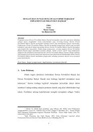
Asia-Pacific Journal <strong>of</strong> Chemical Engineering THE PRODUCTION OF SYNTHESIS GAS FROM NATURAL GAS 761(1962). <strong>Exergy</strong> has been generally referred to as workcapacity or available work. The concept was initiallyintroduced by Gibbs <strong>and</strong> Helmholtz for thermodynamic<strong>analysis</strong> <strong>of</strong> chemical systems. A review on the use <strong>of</strong>exergy in systems <strong>analysis</strong> since its early beginning hasbeen provided in the early millennium year. [2] Bosnjakovic(1960) demonstrated the exergy <strong>analysis</strong> methodon a power plant using the enthalpy–entropy diagram topresent his results. He also made reference to the benefit<strong>of</strong> using exergy <strong>analysis</strong> in other related systems.Trepp (1961) examined exergy losses in refrigerationmachines <strong>and</strong> develop optimum low temperature cycledesign. Beahr (1962) provided an extensive discussionon exergy <strong>and</strong> presented his analytical results by comparingflowcharts <strong>of</strong> exergy <strong>and</strong> energy.Szargut (2005) mentioned that exergy <strong>analysis</strong> isbased upon the second law <strong>of</strong> thermodynamics whichstipulates that all macroscopic processes are irreversible.Every such irreversible process entails a nonrecoverableexergy lost, which is expressed as the product<strong>of</strong> the environment temperature <strong>and</strong> the entropygenerated. The quantity <strong>of</strong> entropy generated is the sum<strong>of</strong> the values <strong>of</strong> the entropy increase for all the bodiestaking part in the process. [3] The elementary irreversiblephenomena that generate entropy are mechanical orhydraulic friction, heat transfer with a finite temperaturegradient, diffusion with a finite gradient <strong>of</strong> concentration,<strong>and</strong> the mixing <strong>of</strong> substances with differentparameters <strong>and</strong> chemical composition.EXISTING CONVENTIONAL PROCESSIn the conventional process at <strong>PT</strong>. <strong>PUSRI</strong> <strong>II</strong>, naturalgas is converted into synthesis gas through steamreformers. The essential configuration <strong>of</strong> the primarysteam reformer is first established by BadischeAnilin <strong>and</strong> Soda Fabrik (BASF) at the end <strong>of</strong>1920s <strong>and</strong> the technology was used in 1931 by St<strong>and</strong>ardOil <strong>of</strong> New Jersey to produce hydrogen from<strong>of</strong>f-gases at its refineries. Since then, the processhas been improved such as by M.W. Kellog at <strong>PT</strong>.<strong>PUSRI</strong> <strong>II</strong>.In this work, process used by <strong>PT</strong>. <strong>PUSRI</strong> <strong>II</strong> Palembangwould be as reference process in <strong>modification</strong>design <strong>and</strong> calculations <strong>analysis</strong>. This reference process,labeled as process A, uses a primary <strong>and</strong> a secondaryreformer in series as shown in Fig. 1. Natural gas, asfeed for the reforming process in the primary reformer,enters the feed preparation step where a heavy hydrocarbon<strong>and</strong> suspended particles are removed. Naturalgas feed to the primary reformer consists <strong>of</strong> 81.90%CH 4 by volume <strong>and</strong> other higher hydrocarbons with5.45% C 2 H 6 , 2.87% C 3 H 8 , 0.44% i-C 4 H 10 , 0.56% n-C 4 H 10 , 0.15% i-C 5 H 12 , 0.08% n-C 5 H 12 , 0.03% C 6+ ,0.20% CO 2 , 0.01% Ar, 1.63% N 2 , <strong>and</strong> 6.68% H 2 .In addition, CO 2 removal, dehydration, <strong>and</strong> desulfurizationare also applied to the feed gas. Natural gasfeed is then preheated to 430 ◦ C <strong>and</strong> pressured to33.87 atm before entering radiant section <strong>of</strong> the primaryNatural Gas Fuel AirFlue GasFEED PREPARATIONSteamPRIMARY REFORMERHeat (Flue Gas)FEED PREHEAT COILT = 703.15 KP = 33.87 atmExhaust tostackCONVECTION SECTION(Coils)Flue GasRADIANT SECTION(Tube Catalyst Ni)T = 1088.15 KP = 31.82 atmHeatAirFlue GasHeat toutilitySECONDARY REFORMER(Tube Catalyst Ni)T = 1251.15 KP = 30.72 atmSYNGAS PREPARATIONT = 644.15 KP = 35.50 atmFigure 1. Block diagram <strong>of</strong> the series reformers, process (A).© 2011 Curtin University <strong>of</strong> Technology <strong>and</strong> John Wiley & Sons, Ltd. Asia-Pac. J. Chem. Eng. 2011; 6: 760–770DOI: 10.1002/apj
762 M. DJONI BUSTAN, S. MAHADZIR AND D. KHARISMADEWI Asia-Pacific Journal <strong>of</strong> Chemical Engineeringreformer. Energy from the hot flue gas is recoveredin the convection section to raise steam or for otheruses.In the radiant section, previously natural gas feedis mixed with saturated steam to give methane-tosteamratio <strong>of</strong> 1 : 4.25 then reacts in endothermicreaction with Ni-catalyst in a tubular reactor <strong>of</strong> theradiant section <strong>of</strong> the primary reformer at 815 ◦ C,31.82 atm. To increase <strong>and</strong> enrich the synthesis gasoutput from the primary reformer, the secondaryreformer is then applied with air supply <strong>and</strong> theoperating condition is 1251.15 ◦ K, 30.72 atm. Its synthesisgas reacts in exothermic reaction in the secondaryreformer with Ni-catalyst supported in a tubularreactor then enters the synthesis gas preparationsteps.Conversion <strong>of</strong> CH 4 in the primary reformer <strong>of</strong> the naturalgas feed only reaches to 51.69%, while all heavierhydrocarbons in the natural gas feed are completely converted.In the secondary reformer, conversion <strong>of</strong> CH 4 is95.48%. Consequently, the overall conversion <strong>of</strong> CH 4from the series reformers reaches to 97.82%.Large amount <strong>of</strong> energy is consumed to raise theprocess temperature from preparation step to 815 ◦ C inthe primary reformer <strong>and</strong> to 978 ◦ C in the secondaryreformer. The overall energy consumed from bothprocesses is 237 534.61 kJ h −1 .Material streams in processes A <strong>and</strong> B <strong>of</strong> this study(based on data <strong>of</strong> January 2009), could be seen fromTable 1, for our focus on a synthesis zone <strong>of</strong> each blockdiagram.The calculation <strong>of</strong> the material <strong>and</strong> energy balancesare given in Table 3 <strong>and</strong> are based on the previous studyabout natural gas conversion <strong>and</strong> will not be discussedhere, <strong>and</strong> only the calculation steps <strong>and</strong> results areshowed in this article. The exergy losses <strong>of</strong> processA in every step are shown in Table 4. It is shown thatthe exergy lost in process A is high. Clearly, althoughthe overall conversion for the reforming could reachup to 97.82%, the consumption <strong>of</strong> energy, fuel, <strong>and</strong>the exergy losses in this process are definitely highbecause these parameters have not been optimized inthe design.PROPOSED PROCESS MODIFICATION<strong>Exergy</strong> <strong>analysis</strong> with a <strong>flowsheet</strong>ing simulator for synthesisgas production from natural gas to becomemethanol as a final product has been learned by Hinderinket al. [4,12] In their method, they have implementeda set <strong>of</strong> external subroutines that have beenintegrated with a <strong>flowsheet</strong>ing simulator, in order tocalculate exergies <strong>of</strong> material streams along with thetraditional energy <strong>and</strong> mass-balance calculations. Theyproposed four different pathways for the process: conventionalsteam reforming, conventional steam reforming<strong>and</strong> pre-reformer; combined reforming with a naturalgas bypass, <strong>and</strong> convective reforming parallel tonon-catalytic partial oxidation.Run from those types <strong>of</strong> pathways as reference byusing the operating condition <strong>and</strong> material streamssimilar to process A in our work, we have calculated itsconversion <strong>and</strong> exergy <strong>analysis</strong> <strong>of</strong> each process whichwould not be discussed <strong>and</strong> compared in this article.Material streams input in the synthesis part <strong>of</strong> thoseprocesses are similar to process A, which is shownin Table 1 for primary reformer input at temperature703.15 K <strong>and</strong> pressure 33.87 atm.The block diagram <strong>of</strong> each process is shown inFig. 2 for conventional steam reforming process (a) <strong>and</strong>Table 1. Material streams <strong>of</strong> processes A <strong>and</strong> B.CompoundsPrimary reformerinput (% kmole/h)Process ASecondary reformerinput (% kmole/h)Partial oxidation(% kmole/h)Process BSteam reformer(% kmole/h)Natural gasCH 4 18.37 5.38 59.00 5.69C 2 H 6 1.29 0.00 4.15 0.00C 3 H 8 0.81 0.00 2.59 0.00C 4 H 10 0.25 0.00 0.82 0.00CO 0.00 4.52 0.00 12.39CO 2 0.06 4.92 0.20 0.21H 2 0.86 31.42 2.77 10.24N 2 0.30 16.21 0.96 14.61Ar 0.00 0.19 0.01 0.00O 2 0.00 4.31 29.50 0.00H 2 O (steam) 78.05 33.04 0.00 56.87Methane : Steam input ratio 1 : 4.25 – – 1 : 10Methane : O 2 ratio – – 1 : 0.5 –N 2 : H 2 output ratio – 1 : 3 – 1 : 3© 2011 Curtin University <strong>of</strong> Technology <strong>and</strong> John Wiley & Sons, Ltd. Asia-Pac. J. Chem. Eng. 2011; 6: 760–770DOI: 10.1002/apj
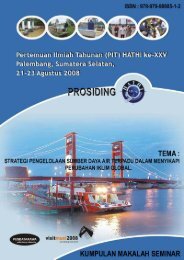
Asia-Pacific Journal <strong>of</strong> Chemical Engineering THE PRODUCTION OF SYNTHESIS GAS FROM NATURAL GAS 763Natural GasFuel AirFlue GasFEED PREPARATIONSteamHeat (Flue Gas)FEED PREHEAT COILPRIMARY REFORMERExhaust tostackCONVECTION SECTION(Coils)Flue GasRADIANT SECTION(Tube Catalyst Ni)HeatFlue GasSYNGAS PREPARATIONNatural Gas Fuel AirFlue GasFEED PREPARATIONSteamPRIMARY REFORMERHeat (Flue Gas)FEED PREHEAT COILNatural GasExhaustto stackCONVECTION SECTION(Coils)Flue GasRADIANT SECTION(Tube Catalyst Ni)NitrogenAirHeatOxygenAIRSEPARATORFlue GasHeat to utilityFlue GasPARTIAL OXIDATION(Tube Catalyst Rh)FuelAirSYNGAS PREPARATIONFigure 2. (a) Block diagram <strong>of</strong> the conventional steam reforming process (A). (b) Blockdiagram <strong>of</strong> the combined reforming with natural gas baypass process (B).combined reforming with a natural gas bypass process(b).From these two processes (Fig. 2(a) <strong>and</strong> (b)), it isknown that both processes give no satisfied conversion<strong>of</strong> methane <strong>and</strong> yield <strong>of</strong> hydrogen <strong>and</strong> carbon dioxidegas compared to process A as reference <strong>and</strong> also highin exergy losses.On the basis <strong>of</strong> those processes results <strong>of</strong> calculationslearned before <strong>and</strong> its weaknesses <strong>and</strong> als<strong>of</strong>rom weaknesses <strong>of</strong> process A as our reference in thisarticle, process <strong>modification</strong> is proposed by adding apartial oxidation process before the primary reformer<strong>and</strong> eliminating the secondary reformer. The modifiedprocess is designated as process B. Process Bhas been proposed to optimize the process design inthe production <strong>of</strong> synthesis gas from natural gas <strong>and</strong>the improvement in exergy losses will be comparedin reference to process A. Process B is described© 2011 Curtin University <strong>of</strong> Technology <strong>and</strong> John Wiley & Sons, Ltd. Asia-Pac. J. Chem. Eng. 2011; 6: 760–770DOI: 10.1002/apj
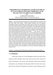
764 M. DJONI BUSTAN, S. MAHADZIR AND D. KHARISMADEWI Asia-Pacific Journal <strong>of</strong> Chemical EngineeringFuelAirNatural GasFEED PREPARATIONFuelAirFEED PREHEAT COILNaturalGasT = 703.15 KP = 33.87 atmOxygenAirAIRSEPARATORFlue GasPARTIAL OXIDATION(Tube Catalyst Rh)T = 1173.15 KP = 20 atmExhaust tostackCONVECTION SECTION(Coils)NitrogenSteamSteamSTEAM REFORMER(Tube Catalyst Ni)T = 773.15 KP = 20 atmSYNGASPREPARATIONT = 664.15 KP = 35.50 atmFigure 3. Block diagram <strong>of</strong> the modified <strong>flowsheet</strong>ing reformer, process (B).below, while the block diagram for calculating exergies<strong>of</strong> the material streams is shown in Fig. 3.The operating conditions are taken from the previousstudy. [5]Figure 3 illustrates the major process steps <strong>of</strong> themodified <strong>flowsheet</strong>ing reformer in a block diagram. Thepartial oxidation process has been added before theprimary reformer <strong>and</strong> the secondary reformer eliminatedin process B. Natural gas with the same characteristics<strong>and</strong> compositions with process A supplies as a feed forthe partial oxidation process, previously it will enterthe feed preparation steps. In this first step, heavyhydrocarbon <strong>and</strong> suspended particles separation, CO 2removal <strong>and</strong> dehydration process are applied to thenatural gas feed. Similar to the process A, natural gasfeed is then preheated to the temperature <strong>of</strong> 430 ◦ C inthe feed preheat coils <strong>and</strong> pressured to 33.87 atm, toenter the partial oxidation process. Natural gas feed isthen mixed with limited oxygen to give methane-tooxygenratio <strong>of</strong> 1 : 0.5 <strong>and</strong> reacts in exothermic reactionwith Rh-catalyst in a tubular reactor <strong>of</strong> the partialoxidation, [6,7] at the operating condition 900 ◦ C, 20 atm.To increase <strong>and</strong> enrich the synthesis gas outputfrom the partial oxidation, synthesis gas output is thenmixed with steam in methane-to-steam ratio <strong>of</strong> 1 : 10 inthe primary/steam reformer at the operating condition500 ◦ C, 20 atm. Its synthesis gas reacts in exothermicreaction with Ni-catalyst supported in a tubular reactor<strong>of</strong> the primary reformer. Nitrogen has been added inthe primary/steam reformer in this process because inthe process A as a reference condition to the next stepto produce ammonia, nitrogen is needed with ratio <strong>of</strong>N 2 -to-H 2 1:3.Material streams in this modified <strong>flowsheet</strong>ingreformer (process B) could be seen from Table 1 previewedbefore, for focus in a synthesis zone <strong>of</strong> Figure 3block diagram. Material streams <strong>of</strong> natural gas feedcompositions in process B are same as process A.EXERGY CALCULATIONS OF THE MATERIALSTREAMSThe overall reactions <strong>and</strong> their st<strong>and</strong>ard Gibbs energy<strong>of</strong> reactions presented for the conversion <strong>of</strong> naturalgas to synthesis gas for each process, is determined inTable 2. [8,9]In Table 2, the minus <strong>of</strong> st<strong>and</strong>ard Gibbs energy <strong>of</strong> theoverall reaction is denoted as available reaction exergy.It plays an important role in underst<strong>and</strong>ing the exergylosses associated to chemical reactions.In basic thermodynamics calculation <strong>of</strong> the materialstreams, the conversion <strong>and</strong> fraction equations wereperformed <strong>and</strong> adopted from Smith <strong>and</strong> Van Ness. [10]Determining the reactions that occur in catalytic partialoxidation process from natural gas with higher hydrocarbonsexist would be the first step to do in thermodynamicscalculation with certain pressure <strong>and</strong> range<strong>of</strong> temperature for trial the best operating condition.© 2011 Curtin University <strong>of</strong> Technology <strong>and</strong> John Wiley & Sons, Ltd. Asia-Pac. J. Chem. Eng. 2011; 6: 760–770DOI: 10.1002/apj
Asia-Pacific Journal <strong>of</strong> Chemical Engineering THE PRODUCTION OF SYNTHESIS GAS FROM NATURAL GAS 765Table 2. The overall reactions.Process Reactions G 0 r 298K (kJ kmole −1 )AB1. In the primary reformer, from natural gas to synthesis gasCH 4 + H 2 O ⇔ CO + 3H 2 141 863C 2 H 6 + 2H 2 O ⇔ 2CO + 5H 2 214 661C 3 H 8 + 3H 2 O ⇔ 3CO + 7H 2 298 499C 4 H 10 + 4H 2 O ⇔ 4CO + 9H 2 349 042CO + H 2 O ⇔ CO 2 + H 2 −28 6182. In the secondary reformer, from synthesis gas to enriched synthesis gasCH 4 + H 2 O ⇔ 3H 2 + CO 141 8632H 2 + O 2 ⇔ 2H 2 O −457 144CO + O 2 ⇔ 2CO 2 −651 5491. In the catalytic partial oxidation, from natural gas to synthesis gas2CH 4 + O 2 ⇔ 2CO + 4H 2 −86 709C 2 H 6 + O 2 ⇔ 2CO + 3H 2 −242 4832C 3 H 8 + 3O 2 ⇔ 6CO + 8H 2 −387 217C 4 H 10 + 2O 2 ⇔ 4CO + 5H 2 −565 2462CO + O 2 ⇔ 2CO 2 −257 1902. In the steam reformer, from synthesis gas to enriched synthesis gasCH 4 + H 2 O ⇔ CO + 3H 2 141 863CO + H 2 O ⇔ CO 2 + H 2 −28 618To calculate the equilibrium mixture for multi-reactionequilibria, we need the equilibrium constant K for thereaction, <strong>and</strong> is shown in Eqn (1).−RT ln K = ∑ iυ i G 0 i ≡ G 0 (1)The final term G 0 is the conventional way <strong>of</strong> representingthe quantity ∑ i υ iGi 0 . It is called the st<strong>and</strong>ardGibbs energy change <strong>of</strong> reaction. The function <strong>of</strong> G 0is the difference between the Gibbs energies <strong>of</strong> theproducts <strong>and</strong> reactants (weighted by their stoichiometriccoefficients) when each species in its st<strong>and</strong>ard stateas a pure substance at the system temperature <strong>and</strong> at afixed pressure. Thus, the value <strong>of</strong> G 0 is fixed for agiven reaction once the temperature is established <strong>and</strong>is independent <strong>of</strong> equilibrium pressure <strong>and</strong> composition.And, G 0 /RT could be explained by Eqn (2).G 0RT = G 0 0 − H 00 + H 00RT 0 RT + 1 T ICPH − ICPS (2)Integral Differential Heat Capacity for EnthalpyCalculations (ICPH) <strong>and</strong> Integral Differential HeatCapacity for Entropy Calculations (ICPS) are symbolsfor computational purposes as described in Eqns (3)<strong>and</strong> (4).∫ TCP0 ICPH =T 0R dT = (A)T 0(τ − 1)+ B2 T 0 2 (τ 2 − 1) + C 3 T 0 3 (τ 3 − 1)+ D ( ) τ − 1(3)T 0 τICPS =+∫ TT 0C 0 PR[BT 0 +dT= A ln τT(CT0 2 + Dτ 2 T02) ( τ + 12)](τ − 1)(4)The evaluation <strong>of</strong> the integral ∫ C p dT is accomplishedby substitution for C p , followed by formal integration,for temperature limits <strong>of</strong> T 0 <strong>and</strong> T , whereτ = T T 0(5)Thus, G 0 /RT (= −ln K) as given by Eqn (2) isreadily calculated at any temperature from st<strong>and</strong>ardheat <strong>of</strong> reaction <strong>and</strong> the st<strong>and</strong>ard Gibbs energy change<strong>of</strong> reaction at a reference temperature, T 0 (usually298.15 ◦ K) <strong>and</strong> from two functions which can becalculated by st<strong>and</strong>ard computational procedures.When two or more reactions proceed simultaneously,mole fractions y i <strong>of</strong> the species are related to ε or calledreaction coordinate, characterized the extent or degreeto which a reaction has taken place, shown by Eqn (6).y i =n i0 + ∑ jn 0 + ∑ jv i,j ε jv j ε j(i = 1, 2, . . . N ) (6)where j is the reaction index, <strong>and</strong> associates a separatereaction coordinate ε j with each reaction. The stoichiometricnumbers are doubly subscripted to identify their© 2011 Curtin University <strong>of</strong> Technology <strong>and</strong> John Wiley & Sons, Ltd. Asia-Pac. J. Chem. Eng. 2011; 6: 760–770DOI: 10.1002/apj
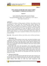
766 M. DJONI BUSTAN, S. MAHADZIR AND D. KHARISMADEWI Asia-Pacific Journal <strong>of</strong> Chemical Engineeringassociation with both a species <strong>and</strong> a reaction. Thus,υ i,j designates the stoichiometric number <strong>of</strong> species iin reaction j .And, when the equilibrium state in a reacting systemdepends on two or more independent chemical reactions,the equilibrium composition can be found by adirect extension <strong>of</strong> the methods developed for singlereactions. If the equilibrium mixture is an ideal gas, itmay be written as Eqn (7), where P 0 = 1 atm.∏( )(y i ) v i,j P −vj=P 0 K j (7)iThe mole fractions in Eqn (7) may be solved byusing the mathematical program for the multireactionequilibria such Maple 11.Heat requirements <strong>of</strong> the process (Q) are expressedby the summation <strong>of</strong> heat input to the reaction process<strong>and</strong> the heat <strong>of</strong> reactions itself as shown inEqns (8) <strong>and</strong> (9), respectively.Q = Q input + Q reactions (8)(Q = nR) (Cp0∫ )TT 0R dT + Hro 0 + R Cp0T 0R dT∫ T(9)In Eqn (9), Hr00 is heat <strong>of</strong> reaction at referencetemperature T 0 .In calculating exergies <strong>of</strong> the material streams, thefollowing steps <strong>of</strong> calculating were performed <strong>and</strong>adopted from Ahern. [3] A primary use <strong>of</strong> the exergy<strong>analysis</strong> is to show the location, type, <strong>and</strong> magnitude <strong>of</strong>the exergy losses, in a system. [11] As a result, the systemefficiency can be effectively increased by reducing theselosses. The exergy losses are generated throughout thesystem by irreversible production <strong>of</strong> entropy caused bythe non-ideal performance inherent in all real systems<strong>and</strong> components.The exergy lost results from heat loss during combustioncould be calculated by using Eqn (10). This wasassumed to be (1 - overall efficiency) <strong>and</strong> considered asa direct exergy loss as it reduced the available work inthe fuel by that amount.Ex a = Q release <strong>of</strong> fuel × (1 − overall efficiency)× mole <strong>of</strong> fuel (10)The exergy <strong>of</strong> fuel is Ex 1,7 the heat release fromnatural gas fuel to the furnace.<strong>Exergy</strong> lost resulting from transfer <strong>of</strong> chemical energyto heat energy is calculated using Eqn (11). During thecombustion <strong>of</strong> the fuel, the remainder <strong>of</strong> the chemicalenergy is transferred into thermal energy,Ex 2,8 = (Q release <strong>of</strong> fuel × mole <strong>of</strong> fuel) − Ex a (11)A transfer <strong>of</strong> useful chemical energy into thermalenergy is an irreversible process expressed by Eqn (12),Ex b = m 9,4 (H out − H in ) T 0T g(12)The exergy loss resulting from a heat transfer betweennatural gas fuel <strong>and</strong> feed <strong>of</strong> process shows in Eqn (13).[Ex c = T 0 (m 9,4 ) (S out − S in ) − (H ]out − H in )T g(13)The total exergy loss <strong>of</strong> fuel natural gas to naturalgas feed/synthesis gas in the process is Ex b + Ex c .Furthermore, the exergy loss during the outflow <strong>of</strong>synthesis gas <strong>of</strong> certain process in piping from one stepprocess to the other is expressed in Eqn (14).Ex 3,5 = (H out − H in ) − T 0 (S out − S in ) (14)In Figs 4 <strong>and</strong> 5, a synthesis gas in conditions 4 <strong>and</strong>6 has a work capacity, soEx 4,6 = (H 4,6 − H 9,4 ) − T 0 (S 4,6 − S 9,4 ) (15)Moreover, the exergy lost in process is expressed byEqn (16) below.Ex d = Ex 3,5 − Ex 4,6 (16)The exergy loss <strong>of</strong> friction from the partial oxidationto the steam reformer or from the primaryreformer to the secondary reformer or from the steamreformer/secondary reformer to the synthesis gas preparationis(P2Ex e = m 3,5 − P )1(17)ρ 2 ρ 1A heat transfer in piping is m(H 3,5 − H 4,6 ).Figure 4 describes the material <strong>and</strong> energy calculationssteps in the proposed process <strong>modification</strong>. Thecomposition moles input used is similar to the existingconventional process A. It is divided into two bigblocks, named 1 <strong>and</strong> 2.Block 1 is the step for calculating material conversion<strong>and</strong> moles fraction <strong>of</strong> natural gas that reacts in a process.Furthermore, block 2 is the step for calculating theenergy streams in a process that is continuing from stepsin block 1.Mass <strong>and</strong> heat input <strong>of</strong> the material streams from theseries reformers <strong>of</strong> process A <strong>and</strong> modified reformer© 2011 Curtin University <strong>of</strong> Technology <strong>and</strong> John Wiley & Sons, Ltd. Asia-Pac. J. Chem. Eng. 2011; 6: 760–770DOI: 10.1002/apj
Asia-Pacific Journal <strong>of</strong> Chemical Engineering THE PRODUCTION OF SYNTHESIS GAS FROM NATURAL GAS 767Estimate the reactions occur in a process,variations temperature <strong>and</strong> fixed pressureconditionCalculate ∆G°, ∆H° in st<strong>and</strong>ard reference° °temperature <strong>of</strong> 298 °KCalculate ICPH <strong>and</strong> ICPS for all temperaturevariations <strong>and</strong> reactionscondition at <strong>PT</strong>. <strong>PUSRI</strong> <strong>II</strong> reformer furnace. Natural gasfuel compositions consist <strong>of</strong> CH 4 64.61%, C 2 H 6 7.97%,C 3 H 8 7.08%, i-C 4 H 10 1.25%, n-C 4 H 10 1.76%, i-C 5 H 121.01%, n-C 5 H 12 0.56%, <strong>and</strong> CO 2 15.76% moles.The exergy calculation <strong>of</strong> the material streams ateach point <strong>of</strong> flows, based on the block diagram in theprocess descriptions, is described in Figs 5 <strong>and</strong> 6 forthe related processes.Calculate ∆G° for all temperature variations<strong>and</strong> reactionsCalculate K in all temperature variations <strong>and</strong>reactionsCalculate ξ (conversion) in each reaction withMaple 11 programCalculate y i (mole fraction) for all componentsin reactionsBlock 1Calculate Q input , Q reactionsCalculate Q total = Q input + Q reactionsBlock 1Figure 4. Block flow <strong>of</strong> calculation <strong>of</strong> material <strong>and</strong> energystreams.process B for the same initial feed <strong>of</strong> a raw natural gasis shown in Table 3Assumption has been taken for the conventionalcombustion temperature, which is 1927 ◦ C <strong>and</strong> theambient temperature is 25 ◦ C. The overall efficiency <strong>of</strong>the furnace is 88% with heat release <strong>of</strong> the natural gasfuel is 15 189 Btu lb −1 based on the actual operatingRESULTS AND DISCUSSIONThe calculation <strong>of</strong> exergy at discrete points in a systemwill indicate the total exergy change, reversible <strong>and</strong>irreversible in the process <strong>and</strong> in the equipment betweenany two points. These exergy values are explicit valuesrelative to the reference condition <strong>of</strong> the surroundingenvironment. On the basis <strong>of</strong> the calculation <strong>of</strong> exergyperformed, the results <strong>of</strong> the exergy <strong>analysis</strong> are shownin Tables 4 <strong>and</strong> 5.The overall reactions <strong>of</strong> natural gas feed occurs inthe primary reformer is endothermic reaction, that consists<strong>of</strong> higher hydrocarbons reactions. From Table 4, itcan be seen that the largest amount <strong>of</strong> the exergy lostis in the primary reformer that accounts for 95.17%<strong>of</strong> the total exergy lost in process A. The presence<strong>of</strong> high exergy lost in the primary reformer may indicatea poor match between the quality <strong>of</strong> the energysupplied to the process <strong>and</strong> the quality required bythe process to perform a given task. This mismatchresults in large irreversibility. Heat released by fuel <strong>of</strong>natural gas can reach temperature to 1927 ◦ C throughthe conventional combustion furnace, while the maximumtemperature required by the process only reaches815 ◦ C.In the secondary reformer, the exergy loss is inthe minimum percentage in which the temperatureoperation needed reaches 978 ◦ C for the exothermicreaction occurred with large amounts <strong>of</strong> moles input<strong>and</strong> heat used. Although the exergy values alwaysSyngas PRSyngas PRAir3 4Fuel In Flue Gas Out Fuel InFlue Gas OutPRIMARYSECONDARYREFORMERREFORMER12 78(PR)(SR)95Steam Natural Gas Feed Syngas SRTo SyngasPreparation (SP)6Figure 5. <strong>Exergy</strong> <strong>analysis</strong> diagram <strong>of</strong> the series reformers, process (A).© 2011 Curtin University <strong>of</strong> Technology <strong>and</strong> John Wiley & Sons, Ltd. Asia-Pac. J. Chem. Eng. 2011; 6: 760–770DOI: 10.1002/apj
768 M. DJONI BUSTAN, S. MAHADZIR AND D. KHARISMADEWI Asia-Pacific Journal <strong>of</strong> Chemical EngineeringTable 3. Mass <strong>and</strong> heat input <strong>of</strong> the material streams.ProcessTotal moles input(kmole h −1 )Total heat input(kJ h −1 )A 1. In the primary reformer, from natural gas to synthesis gas 5857.06 99 392 276.412. In the secondary reformer, from synthesis gas to enriched synthesis gas 9657.16 265 845 258.21B 1. In the catalytic partial oxidation, from natural gas to synthesis gas 1823.88 34 765 753.392. In the steam reformer, from synthesis gas to enriched synthesis gas 7628.99 158 957 291.79Syngas POXSyngas POXSteamNitrogen3 4Fuel In Flue Gas Out Fuel InFlue Gas Out1PARTIALOXIDATION(POX)2 7STEAMREFORMER(SR)89Oxygen Natural Gas Feed Syngas SR5To SyngasPreparation (SP)6Figure 6. <strong>Exergy</strong> <strong>analysis</strong> diagram <strong>of</strong> the modified <strong>flowsheet</strong>ing reformer,process (B).show positive to the reference surrounding environment,in the secondary reformer it shows negative value.The zero reference for enthalpy <strong>and</strong> entropy valuesin the literature <strong>of</strong>ten results in positive <strong>and</strong> negativevalues <strong>of</strong> exergy calculation for the system. Totalexergy losses <strong>of</strong> the entire processes in process A are2 821 615.23 MJ h −1 , its amounts will reduce throughthe modified <strong>flowsheet</strong>ing reformer which is shown inTable 5.As shown in Table 5, the total exergy lost for theentire process B is 1 091 015.74 MJ h −1 . The <strong>flowsheet</strong><strong>modification</strong> <strong>of</strong> process A is done through replacement<strong>of</strong> the secondary reformer with a partial oxidationprocess upstream <strong>of</strong> the primary reformer. Process Bshows a significant potential reduction in the totalexergy lost in primary reformer (steam reformer) byup to 78.11% relative to the conventional process A.Furthermore, the operating conditions in the primaryreformer <strong>of</strong> process B is reduced to 500 ◦ C, 20 atmthereby reducing the consumption <strong>of</strong> natural gas fuelin the reformer. Heat released from the exothermicpartial oxidation process may be recovered to provideheating for the endothermic reaction in steam reformer<strong>of</strong> process B.So, the overall exergy losses in process A can bereduced through applying a <strong>modification</strong> such in processB, as much as% exergy savings( )exergy losses in process A − exergy losses in process B=exergy losses in process A× 100%( )2821615.23 MJ/h − 1091015.74 MJ/h=× 100%2821615.23 MJ/h% exergy savings = 61.33%CONCLUSIONSThis article presents a path for calculating exergy lossesfor each step in the main parts <strong>of</strong> synthesis gas productionfrom natural gas. The path is integrated withthe modified <strong>flowsheet</strong>ing reformer <strong>of</strong> process B <strong>and</strong>compared to the series reformers <strong>of</strong> process A. <strong>Exergy</strong><strong>analysis</strong> is found to be useful for the process <strong>analysis</strong>.It provides an objective measurement for selecting<strong>and</strong> judging processes regard to their energy (or exergy)utilization. The overall exergy losses (%) in process Acan be reduced until 61.33% through <strong>modification</strong> toprocess B. The result is achieved for the same initialfeed <strong>of</strong> a raw natural gas. Furthermore, the exergy loss© 2011 Curtin University <strong>of</strong> Technology <strong>and</strong> John Wiley & Sons, Ltd. Asia-Pac. J. Chem. Eng. 2011; 6: 760–770DOI: 10.1002/apj
Asia-Pacific Journal <strong>of</strong> Chemical Engineering THE PRODUCTION OF SYNTHESIS GAS FROM NATURAL GAS 769Table 4. The exergy <strong>analysis</strong> <strong>of</strong> the series reformers (process A).Station orcomponent<strong>Exergy</strong>(MJ h −1 )Change inexergy (MJ h −1 )Heat transfer(MJ h −1 )Chemicalchange (MJ h −1 )Heat transfer(MJ h −1 )<strong>Exergy</strong> lossesFriction(MJ h −1 )Heat rejection(MJ h −1 )Total(MJ h −1 )Total exergyloss (%)1 49.94Furnace primary 5.99 5.99 5.99 −0.00(Ex a)2 43.95Primary reformer −2 685 274.29 43.95 −1 306 860.27 −1 378 414.01 −2 685 274.29 95.17(Ex b + Ex c) (Ex b) (Ex c)3 −1187.94Piping 898.13 −156 418.00 −156 418.00 0.01 −156 417.99 5.54(PR to SR) (Ex d )4 −2086.07Secondary reformer 22 955.61 117.55 1 222 160.24 −1 199 204.63 22 955.61 −0.00(Ex b + Ex c) (Ex b) (Ex c)5 931.45Piping −0.30 −2900.54 −2900.54 −0.05 −2900.59 0.10(SR to SP) (Ex d )6 931.757 133.58Furnace secondary 16.03(Ex a) 16.03 16.03 −0.008 117.55−2 821 615.23 100.00© 2011 Curtin University <strong>of</strong> Technology <strong>and</strong> John Wiley & Sons, Ltd. Asia-Pac. J. Chem. Eng. 2011; 6: 760–770DOI: 10.1002/apj
770 M. DJONI BUSTAN, S. MAHADZIR AND D. KHARISMADEWI Asia-Pacific Journal <strong>of</strong> Chemical EngineeringTable 5. The exergy <strong>analysis</strong> <strong>of</strong> modified <strong>flowsheet</strong>ing reformer (process B).Station orcomponent<strong>Exergy</strong>(MJ h −1 )Change inexergy(MJ h −1 )Heattransfer(MJ h −1 )Chemicalchange(MJ h −1 )Heattransfer(MJ h −1 )<strong>Exergy</strong> LossesFriction(MJ h −1 )Heatrejection(MJ h −1 )Total(MJ h −1 )Totalexergyloss (%)1 17.47Furnace POX 2.10 2.10 2.10 −0.00(Ex a )2 15.37Partial −500 907.94 15.37 270 586.09 −771 494.03 −500 907.94 45.91oxidation (Ex b + Ex c ) (Ex b ) (Ex c )3 1369.34Piping −137.05 −2504.92 −2504.92 −0.01 −2504.92 0.23(POX to SR) (Ex d )4 1506.40Steam −587 614.55 70.29 −295 897.19 −291 717.36 −587 614.55 53.86reformer (Ex b + Ex c ) (Ex b ) (Ex c )5 −209.17Piping (SR to 0.00 0.00 0.00 −0.01 −0.01 0.00SP) (Ex d )6 −209.177 79.87Furnace SR 9.58 9.58 9.58 −0.00(Ex a )8 70.29−1 091 015.74 100.00in the primary reformer itself can be reduced to 78.11%relative to process A.NOMENCLATURET 0T 0 , TyThe ambient temperature, ◦ KReference temperature; Process temperature,◦ KMole fractionυ Stoichiometric numberεReaction coordinateρ 2 , ρ 1 Density <strong>of</strong> components in the materialstreams at point 2 <strong>and</strong> 1, kg cm −3H Total enthalpy <strong>of</strong> material streams, kJkmole −1S Total entropy <strong>of</strong> material streams, kJkmole −1G 0 , G 0 0 Gibbs energy, st<strong>and</strong>ard Gibbs energy <strong>of</strong>pure component at 298.15 ◦ K, J mole −1H 0 , H 0 0 Enthalpy, st<strong>and</strong>ard enthalpy <strong>of</strong> pure componentat 298.15 ◦ K, J mole −10C p Heat capacityEx 1,2,...,9 The exergy in point 1 or 2 or . . . to 9,kJ h −1K Equilibrium constantm Mole input to the process, molen i,0 Mole <strong>of</strong> pure component; Mole total, moleP 2 , P 1 Pressure <strong>of</strong> process at point 2 <strong>and</strong> 1, atmP 0 , P Reference pressure; Process pressure, atmQ Heat, kJ h −1R Universal gas constant, J mol −1 K −1T g The conventional combustion furnacetemperature, ◦ KREFERENCES[1] I. Dincer, M. Rosen. <strong>Exergy</strong>: Energy, Environment, <strong>and</strong>Sustainable Development, Elsevier: Oxford, United Kingdom,2007.[2] E. Sciubba, G. Wall. Int. J. Thermodyn., 2007; 10(1), 1–26.[3] J.E. Ahern. The <strong>Exergy</strong> Method <strong>of</strong> Energy Systems Analysis,John Wiley & Sons Inc: USA, 1980.[4] A.P. Hinderink, F.P.J.M. Kerkh<strong>of</strong>, A.B.K. Lie, J.D.S. Arons,H.J.V.D. Kooi. Chem. Eng. Sci., 1996; 51(20), 4693–4700.[5] M.D. Bustan, S. Haryati, I.G. Mendera. Studi Analisis Perb<strong>and</strong>inganAntara Konvensional dan Modifikasi FlowsheetingSistem Produksi Syngas Terhadap Konversi dan PenurunanKonsumsi Panas Pada Reformer <strong>PT</strong>. <strong>PUSRI</strong> <strong>II</strong> Palembang,Thesis, Sriwijaya University, Indonesia, 2009.[6] M.V. Twigg. Catalyst H<strong>and</strong>book, Wolfe Publishing Ltd:Engl<strong>and</strong> 2 nd edn., 1989.[7] S. Bharadwaj, L. Schmidt. Catalytic Partial Oxidation <strong>of</strong>Natural Gas to Syngas Fuel. Proc. Tech, 1995.[8] M.R. Felder, R.W. Rousseau. Elementary Principles <strong>of</strong> ChemicalProcesses, John Wiley & Sons Inc: USA, 2005.[9] O. Levenspiel. Chemical Reaction Engineering, Wiley Eastern:New Delhi, 1999.[10] J.M. Smith, H.C. Van Ness. Introduction to ChemicalEngineering Thermodynamics, McGraw-Hill: New York,1987.[11] W.D. Seider, J.D. Seader, D.R. Lewin. Process DesignPrinciples; Synthesis, Analysis <strong>and</strong> Evaluation, John Wiley &Sons Inc: USA, 1999.[12] A.P. Hinderink, F.P.J.M. Kerkh<strong>of</strong>, A.B.K. Lie, J.D.S. Arons,H.J.V.D. Kooi. Chem. Eng. Sci., 1996; 51(20), 4701–4715.© 2011 Curtin University <strong>of</strong> Technology <strong>and</strong> John Wiley & Sons, Ltd. Asia-Pac. J. Chem. Eng. 2011; 6: 760–770DOI: 10.1002/apj