Tolerance design of multistage radial flow submersible pumps
Tolerance design of multistage radial flow submersible pumps
Tolerance design of multistage radial flow submersible pumps
- No tags were found...

You also want an ePaper? Increase the reach of your titles
YUMPU automatically turns print PDFs into web optimized ePapers that Google loves.
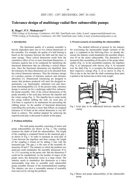
64ISSN 1392 - 1207. MECHANIKA. 2007. Nr.1(63)<strong>Tolerance</strong> <strong>design</strong> <strong>of</strong> <strong>multistage</strong> <strong>radial</strong> <strong>flow</strong> <strong>submersible</strong> <strong>pumps</strong>K. Ragu*, P.V. Mohanram***PSG College <strong>of</strong> Technology, Coimbatore -641 004, TamilNadu state, India, E-mail: raguperumal@hotmail.com**PSG College <strong>of</strong> Technology, Coimbatore -641 004, TamilNadu state, India, E-mail: pvmohanram@yahoo.co.uk1. IntroductionThe functional quality <strong>of</strong> a product assembly isheavily dependent upon one or two critical dimensions <strong>of</strong>the assembly. For example, the quality <strong>of</strong> a ball bearing isbased on the clearance between the balls and the inner orouter racings. These critical dimensions result from thecumulative effect <strong>of</strong> two or more functional dimensions. Atolerance analysis has to be conducted for identifying thefunctional dimensions that are affecting a critical dimension.Once the functional dimensions are identified, thenthe tolerances for these dimensions are to be allocated fromthe critical dimension tolerance. Thus the tolerance <strong>design</strong><strong>of</strong> a product consists <strong>of</strong> tolerance analysis and toleranceallocation [1]. Dimensional tolerancing are <strong>design</strong>ed toensure that products produced will meet the <strong>design</strong>ed requirements,e.g. functionality, minimum cost and maximuminterchangeability [2]. In the present study, tolerance<strong>design</strong> is carried out for a <strong>multistage</strong> <strong>radial</strong> <strong>flow</strong> <strong>submersible</strong>pump assembly. One <strong>of</strong> the critical dimensions <strong>of</strong> thepump assembly is the axial play between the impeller andthe volute casing (Fig. 1). The impeller has to rotate insidethe casing without rubbing the wall. An axial play <strong>of</strong>2±0.5mm is required to be maintained for preventing therubbing action. As the number <strong>of</strong> functional dimensionscontrolling this axial play is more than fifteen, an assignedtolerance <strong>of</strong> ±0.5mm on the critical dimension is very difficultto achieve. The method adopted for achieving therequired axial play is discussed in details in this paper.3. Present scenario <strong>of</strong> assembling the subassembliesThe method followed at present by the industryfor overcoming the unreasonable length variation <strong>of</strong> thegap L is explained in the following lines. As already discussed,the industry could standardize the assembly dimensionM on the motor subassembly. The dimension P ismeasured after assembling all the parts <strong>of</strong> the pump subassembly(Fig. 3). In the assembled condition, the impellers(Fig. 4, a) interspaced with sleeves (Fig. 4, b) mountedover the shaft (Fig. 4, c) occupies the bottom position intheir respective casings (Fig. 4, d) as shown in (Fig. 5).This is due to the fact that the shaft containing these partsis pulled to the bottom due to their total weight.Fig. 1 Axial play to be maintained between impeller andcasing2. Problem definitionThe total pump assembly consisting <strong>of</strong> motor andpump subassemblies are shown in Fig. 2. The couplingconnects the shafts <strong>of</strong> both the subassemblies. The length<strong>of</strong> the coupling is computed based on the measured gap Las shown in Fig. 3. In order to maintain an axial play <strong>of</strong>2 mm between the impellers and their casings, the length<strong>of</strong> the coupling is found out by adding 2 mm with themeasured gap. The gap L is the sum <strong>of</strong> the assembly dimensionsM and P. The industry in which the problem wasanalyzed could standardize the assembly dimension M to16 ± 0.3 occurring on the motor side. But the dimension Pcould not be standardized. As the number <strong>of</strong> stages <strong>of</strong> thepump varies, this dimension varies to a large extent. Theindustry needs to standardize this dimension as it takesunreasonably long time to assemble each <strong>submersible</strong>pump assembly because <strong>of</strong> the nonstandardized coupling.The industry can save a reasonable amount <strong>of</strong> assemblytime and cost by solving this problem.Fig. 2 Motor and pump subassemblies <strong>of</strong> the <strong>submersible</strong>pump
65by 2 mm in order to centre the impellers. This is accomplishedby choosing the coupling length 2 mm in excess <strong>of</strong>the measured gap L. For ease <strong>of</strong> manufacture, the coupling<strong>of</strong> varying length is split into two, namely a coupling <strong>of</strong>standard length 85 ± 0.2 and a sand guard <strong>of</strong> varyingthickness (Fig. 7). The sand guard is machined to the requiredsize only during the final stage <strong>of</strong> the assembly aftermeasuring the gap in which it is to be fitted. It serves thepurpose <strong>of</strong> preventing sand and other impurities from enteringinto the motor subassembly.Fig. 3 Computation <strong>of</strong> coupling lengthabFig. 5 Pump subassembly Fig. 6 Pump subassemblyin assembledin workingconditionconditioncdFig. 4 Parts <strong>of</strong> pump subassemblyIn the working condition <strong>of</strong> the subassembly, allthe impellers have to be centered within the space availablein the casings (Fig. 6). The shaft has to be pushed upwardsFig. 7 Role <strong>of</strong> sand guard in the assembly
664. <strong>Tolerance</strong> analysis for a five stage pumpThe functional dimensions affecting a critical dimensioncan be identified by conducting tolerance analysison the product. The product shown in Fig. 8 has totally tendimensions. The critical dimension is horizontal distancebetween the hole centre. Functional dimensions affectingthe critical dimension are identified by the tolerance loopas shown in Fig. 8. Starting from the first hole, movingalong the dimension line towards right is considered positiveand vice versa.Fig. 8 Identification <strong>of</strong> functional dimensions affectingcritical dimension using tolerance loopisFor the loop shown in (Fig. 8), the loop equationCritical Dimension +X5 – X3 + X4 = 0 (1)Fig. 9 First impeller in contact with its casingwhere Critical Dimension = -X5 + X3– X4.From the loop equation, it can be identified thatthe functional dimensions X5, X3 and X4 affect the criticaldimension while the remaining seven dimensions do notaffect it. A similar analysis can be conducted on the <strong>pumps</strong>ubassembly to identify functional dimensions affectingthe dimension P.4.1. Assembly parameter affecting tolerance loopThe pump subassembly shown in Fig. 5 has allthe five impellers occupying the bottom positions in theirrespective casings. But in real conditions, all the impellerswill not touch their respective casings simultaneously.Only one impeller will touch the casing while all the otherimpellers will maintain some gap between them and theirrespective casings. Deciding which impeller will touch thecasing is based on the tolerance built up <strong>of</strong> parts <strong>of</strong> theassembly. Thus the tolerance loop varies according to theimpeller that touches the casing. For a pump with fivestages, five different tolerance loops are therefore possiblefor the dimension P.4.2. <strong>Tolerance</strong> loop for five different conditions <strong>of</strong> assemblyThe first condition <strong>of</strong> the assembly is shown inFig. 9. The first impeller is in contact with its casing whilethe other four impellers maintain some gap between themand their respective casings. The loop equation for thiscondition <strong>of</strong> assembly isP = X1 + X27 – X28 – X29 – X17 (2)Fig. 10 Second impeller in contact with its casing
67Fig. 10 shows the second impeller in contact withits casing. The loop equation for this condition isP = X1 + X2 + X24 – X25 – X26 – X15 – X16 – X17 (3)Figs. 11 - 13 show respectively the third, fourthand fifth impellers in contact with their casings. The correspondingequations areP = X1 + X2 + X3 + X21 – X22 – X23 –– X13 – X14 – X15 – X16 – X17 (4)P = X1 + X2 + X3 + X4 + X18 – X19 – X20 –– X11 – X12 – X13 – X14 – X15 – X16 – X17 (5)P = X1 + X2 + X3 + X4 + X5 + X6 – X7 – X8 –– X9 – X10 – X11 – X12 – X13 – X14 – X15–– X16 – X17 (6)Comparing the Eqs. (2) to (6), it can be found thatthe largest tolerance loop occurs with the last impellermaking contact with its casing. Finding the critical dimensionP using Eq. (6) therefore will yield the largest toleranceand it gives the worst condition <strong>of</strong> assembly. Hencetolerance <strong>design</strong> is accomplished by considering the lastimpeller in contact with its casing.Fig. 12 Fourth impeller in contact with its casingFig. 11 Third impeller in contact with its casingFig. 13 Fifth impeller in contact with its casing
684.3. <strong>Tolerance</strong> summationThe value <strong>of</strong> the critical dimension P can befound out from Eq. (6) using three different methodsnamely worst case analysis, normal law and Monte Carlosimulation. The worst case analysis yields the followingresults.P= X1 + X2 + X3 + X4 + X5 + X6 – X7 – X8 – X9 –– X10 – X11 – X12 – X13 – X14 – X15 – X16 –– X17 = 125 + 40 + 40 + 40 + 40 + 4 – 5 – 7 - 20 –– 20 – 20 – 20 – 20 – 20 – 20 -20 - 40= 77p= 0.2 + 0.2 + 0.2 + 0.2 + 0.2 + 0.1+ 0.1 + 0.1++ 0.1 + 0.1 + 0.1 + 0.1 + 0.1 + 0.1 + 0.1 + 0.1 ++ 0.05= 2.15The Monte Carlo simulation technique simulatesthe assembly <strong>of</strong> different parts <strong>of</strong> the pump to make thefinal product. If an assembly is made <strong>of</strong> two componentshaving functional dimensions 7 ± 0.1 and 5 ± 0.08, theassembly dimension can lie between 11.82 and 12.18 asper the worst case analysis. When the assembly is massproduced, the exact location <strong>of</strong> each assembly dimensionin the range 11.82 – 12.18 depends on the locations occupiedby the part dimensions within their respective ranges.The Monte Carlo simulation randomly chooses one locationwithin the range 6.9 – 7.1 for the first dimension andanother random location within the range 4.92 – 5.08 forthe second dimension. The assembly dimension is foundout by summing these part dimension values. Thus thevalue arrived in the first simulation is registered. A number<strong>of</strong> simulations is run by this method and simulations resultsare shown in the form <strong>of</strong> frequency chart and statistics. Thesimulation s<strong>of</strong>tware Crystal Ball [3] is used for this purpose.The resulting dimension and its tolerance can befound out from the statistical output <strong>of</strong> the s<strong>of</strong>tware simulation.The tolerance loop for the five stage <strong>submersible</strong>assembly has totally seventeen functional dimensions asshown in Fig. 13. The nominal value, frequency distributionand the standard deviation <strong>of</strong> all the seventeen dimensionsare the inputs given to the Crystal Ball s<strong>of</strong>tware asshown in Fig. 14. The outputs <strong>of</strong> the s<strong>of</strong>tware are shown inFig. 15 and Fig. 16. The standard deviation <strong>of</strong> the resultingfrequency distribution pattern is 0.19. The resulting dimensiontolerance p is therefore three times the standard deviationi.e., 0.57 mm.P ± p= 77 ± 2.15The worst case approach is based on the assumptionthat all the functional dimensions affecting criticaldimension simultaneously assume their extreme values.But in real practice, the probability <strong>of</strong> all the dimensionsassuming their extreme values is very low. Hence the resultingdimension value arrived using this approach haswider tolerance than what really results in the actual condition.The normal law can be applied to a product assemblyif all the functional dimensions in a tolerance loopfollow normal frequency distribution pattern. If a functionaldimension on a part is arrived by machining thecorresponding surfaces, it can be expected that it will follownormal frequency distribution pattern. In the <strong>submersible</strong>pump assembly under the study, all the functionaldimensions have been arrived by machining in lathe.Therefore normal law can be applied to find the criticaldimension. Applying normal law,____________________________________p= √ 0.2 2 + 0.2 2 + 0.2 2 + 0.2 2 + 0.2 2 + 0.1 2 + 0.1 2 +_____________________________________0.1 2 + 0.1 2 + 0.1 2 + 0.1 2 + 0.1 2 + 0.1 2 + 0.1 2 +_______________0.1 2 + 0.1 2 + 0.05 2 = 0.56P ± p= 77 ± 0.56Fig. 14 Inputs for the Monte Carlo simulation100,000 Trials Frequency Chart99,049 Displayed.021.016.011.005.000Forecast: Frequency Distribution & Statistics76.52 76.76 77.00 77.24 77.48Fig. 15 Frequency distribution <strong>of</strong> the resulting dimension Pfor a five stage pumpStatisticValueTrials 100.000Mean 77Median 77Mode ---Standard Deviation 0.19Variance 0.03Skewness -0.01Kurtosis 3Coeff. <strong>of</strong> Variability 0Range Minimum 76.27Range Maximum 77.75Range Width 1.49Mean Std. Error 0Fig. 16 Statistical output <strong>of</strong> the simulation2130532.50
70five stage pump. Thus a pump with n stages will have npossible tolerance loops. Since tolerance <strong>design</strong> has to beconducted for the worst condition <strong>of</strong> assembly, toleranceloop having maximum number <strong>of</strong> functional dimensionshas to be considered for the analysis. Thus for the fivestage pump, the assembly condition involving the fifthimpeller in contact with its casing has resulted in the largesttolerance loop. The critical dimension value was foundout based on this largest tolerance loop using three differentmethods. The concept <strong>of</strong> selective assembly was usedto overcome the problem <strong>of</strong> nonstandardized couplinglength.8. References1. Hong – Chao Zhang. Advanced Tolerancing Techniques.-JohnWiley and Sons, Inc, 1997.-587p.2. Ngoi, B.K.A., Lim, B.H., Ang, P.S. Nexus method forstack analysis <strong>of</strong> geometric dimensioning andtoleancing problems.-ISSN 0020-7543.-Int. J. <strong>of</strong> Productionresearch, 2000, 38, p.21-37.3. Crystal ball 2000-user manual.4. Val, S., Loban<strong>of</strong>f, Robert Ross, R. CentrifugalPumps: Design and Application.-Mumbai: Jaico publishinghouse, 2003.-577p.5. Creveling C.M. <strong>Tolerance</strong> Design –A Handbook forDeveloping Optimal Specifications.-Addison-Wesley,1997.-423p.K. Ragu, P.V. MohanramDAUGIAPAKOPIŲ PANARDINAMŲJŲ IŠCENTRINIŲSIURBLIŲ LEISTINŲJŲ NUOKRYPIŲPROJEKTAVIMASR e z i u m ėDaugiapakopių išcentrinių siurblių ašinio tarpeliotarp rotoriaus ir jo korpuso kitimas priklauso nuo matmenųgrandinės. Surenkant gaminį ašinis tarpelis keičiasi dėlmovos jungiančios variklį su siurblio pomazgiais. Atlikusvisapusišką analizę šioje pramonės šakoje, nustatyta, kadmovos ilgio standartizuoti negalima. Siurblio pomazgiųleistinųjų nuokrypių analizė buvo atlikta siekiant nustatytireikiamo movos ilgio pokyčio priežastis. Buvo nustatyta,kad n pakopiame siurblyje gali būti n skaičius leidžiamųjųnuokrypių grandinių. Kadangi leistinųjų surinkimo nuokrypiųdydis surinkime turi būti nustatytas blogiausiamatvejui, analizei buvo pasirinktas variantas, kai surinkimassąlygoja didžiausią leistinųjų nuokrypių grandinę. Šiuometu pramonėje pritaikoma metodologija problemiška tuopožiūriu, kad movos ilgis koreguojamas jau surinkus gaminį.Dėl to galutinė gaminio surinkimo trukmė esti neracionaliaiilga. Šiame straipsnyje siūloma selektyvaus surinkimokoncepcija išsprendžia movos ilgio svyravimoproblemas.K. Ragu, P.V. MohanramTOLERANCE DESIGN OF MULTISTAGE RADIALFLOW SUBMERSIBLE PUMPSS u m m a r yAxial play between the impeller and its casing isone <strong>of</strong> the critical dimensions in a <strong>multistage</strong> <strong>submersible</strong>pump assembly. The axial play is introduced in the assemblyusing a coupling that connects the motor and pump subassemblies. The length <strong>of</strong> the coupling could not be standardizedby the industry where this analysis was conducted.<strong>Tolerance</strong> analysis is conducted on the pump subassemblyto identify the causes <strong>of</strong> variation <strong>of</strong> couplinglength. It has been found that there are n possible toleranceloops in a n stage pump. Since the tolerance <strong>design</strong> is to beconducted for the worst case, the assembly condition thatyields the largest tolerance loop has been considered forthe analysis. The methodology currently adopted by industryto overcome the problem <strong>of</strong> variation <strong>of</strong> couplinglength involves machining operation during the assemblystage. It results in unreasonably longer assembly time. Theconcept <strong>of</strong> selective assembly is suggested in this paper toovercome the problem <strong>of</strong> coupling length variation.К. Рагу, П.В. МоганрамПРОЕКТИРОВАНИЕ ДОПУСТИМЫХ ДОПУСКОВПОГРУЖНЫХ МНОГОСТУПЕНЧАТЫХЦЕНТРОБЕЖНЫХ НАСОСОВР е з ю м еИзменение осевой игры между ротором и егокорпусом в многоступенчатых центробежных насосахзависит от размерной цепи. Изменение осевой игрыпри сборке образуется от соединяющей муфты двигателяс модулем насоса. После выполнения всестороннегоанализа в этой отрасли промышленности, оказалось,что длину муфты стандартизировать нельзя.Анализ допустимых допусков модели насоса был произведенс целью определения причины изменения величинынеобходимой длины муфты. Было установлено,что возможно n число цепей допустимых допусковв n ступенчатом насосе. Так как величина допустимыхдопусков при сборке должна быть установлена дляхудшего случая, для анализа был подобран вариант,когда сборочный процесс обусловливает наибольшуюцепь допустимых допусков. В настоящее время напроизводстве применена методология проблематична втом, что длина муфты корригируется после сборкиизделия. Это обусловливает нерационально долгоевремя используемое для конечной сборки изделия. Длярешения проблем колебаний длины муфты в статьепредлагается концепция селективной сборки.Received October 17, 2006