Shorting Pins Application in Wide-Band E-Shaped Patch Antenna
Shorting Pins Application in Wide-Band E-Shaped Patch Antenna
Shorting Pins Application in Wide-Band E-Shaped Patch Antenna
- No tags were found...

You also want an ePaper? Increase the reach of your titles
YUMPU automatically turns print PDFs into web optimized ePapers that Google loves.
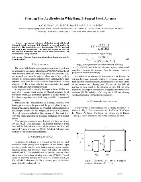
Table 1 presents frequency values after the p<strong>in</strong> <strong>in</strong>sertion atdifferent positions. The Fig. 4 shows the values when p<strong>in</strong>position is Yp=27mm and feed<strong>in</strong>g position Yo=25mm.Table 1 – Lower and higher resonant frequenciesYo(mm)Yp(mm)Lowerfrequency(GHz)Higherfrequency(GHz)43.5 45.0 0.71 1.8137.0 39.0 0.72 1.8032.0 33.0 0.71 1.8025.0 27.0 0.70 2.0619.5 21.0 0.66 2.30Accord<strong>in</strong>g to Table 1, two resonant frequencies appearwhen a p<strong>in</strong> is positioned close to the feed<strong>in</strong>g position, eachone with relative bandwidth of 3%. This is very adequate toapplications where two carriers are necessary. To achievewideband antenna, it is necessary to modify the feed and p<strong>in</strong>positions. As the lower resonant frequency obta<strong>in</strong>ed for F2 is1.8 GHz, the p<strong>in</strong> position Yp=33m is chosen. It is importantto remember that the lower frequency means bigger sizereduction. To obta<strong>in</strong> the feed<strong>in</strong>g position, experiments arenecessary to determ<strong>in</strong>e where the antenna <strong>in</strong>put impedance ismatched to its feed<strong>in</strong>g structure.B. Full E antenna with p<strong>in</strong>, show<strong>in</strong>g smaller dimensions thanE reference antennaThe dimensions, parameters and results for three Eformat antennas of reduced dimension with position p<strong>in</strong>Yp=33mm, thickness h=10mm and air dielectric are on Table2 and 3. The area reduction is relative to the referenceantenna from Fig. 2, of area 31.5 cm 2 .Table 2 – <strong>Antenna</strong> dimensions for p<strong>in</strong> position Yp=33mm13.0 15.0 0.61 2.37<strong>Antenna</strong>LWWsPsLsYo8.0 9.0 0.57 2.96(mm)(mm)(mm)(mm)(mm)(mm)1.0 3.0 0.54 3.00A 40 35 5 6 31 12B 40 40 5 6 34 11C 50 40 5 6 34 1010S11 (dB)0-10-20-30-400.5 1 1.5 2 2.5 3Frequency (GHz)Fig. 4 - E shape antenna with p<strong>in</strong> and doubleresonance (0.70 and 2.06 GHz), for Yo=25mmand Yp=27 mm.Table 3 – <strong>Antenna</strong> results for p<strong>in</strong> position Yp=33mm<strong>Antenna</strong>BW(%)BW(MHz)Areareduction(%)A 10 260 55B 13 350 50C 16 440 37The antennas A, B and C show <strong>in</strong>crease <strong>in</strong> its lowerfrequency due p<strong>in</strong> to the application and lower Ls parameter.The bandwidth is also decreased because it has lower volume,accord<strong>in</strong>g to equations (1) and (2). The simulated bandwidthvalues, center frequency and return loss for the three antennasare shown <strong>in</strong> Fig. 5. The Fig. 5 also shows measured valuefor antenna C.2009 SBMO/IEEE MTT-S International Microwave & Optoelectronics Conference (IMOC 2009) 231
YoYoC). The goal is to f<strong>in</strong>d the p<strong>in</strong> position where the higherresonant frequency has greater reduction.S11 (dB)0-5-10-15-20<strong>Antenna</strong> A (predicted)-25 <strong>Antenna</strong> B (predicted)<strong>Antenna</strong> C (predicted)<strong>Antenna</strong> C (measured)-302 2.2 2.4 2.6 2.8 3Frequency (GHz)Fig. 5– Return losses for the reduced size E antenna withthe p<strong>in</strong> position Yp=33mm and for three antennas: BW260 MHz (antenna A), 350 MHz (antenna B) and 440MHz (antenna C).C. Half E antenna, with p<strong>in</strong>Similar to the process employed to a full E antennadescribed on item B, a p<strong>in</strong> will be applied to the half Eantenna with dimensions L=35mm, W=45mm, Ls=35mm,Ps=6mm and Ws=4mm, with h=10mm and air dielectric(Fig.6).L- Region ATable 4 presents values and results for the p<strong>in</strong> <strong>in</strong> the RegionA. The Fig.7 shows the geometry and Fig.8 is an examplewhen Yp=15mm and Yo=13mm S<strong>in</strong>ce the antenna isasymmetrical, three resonant frequencies (F1, F2 and F3) arepresent, where the major reduction of F3 (higher frequency)will <strong>in</strong>dicate the position to apply the p<strong>in</strong> to m<strong>in</strong>imize size ofthe antenna (Yp=32mm or 13 mm from the back border).Table 4 – Resonant frequencies <strong>in</strong> Region AYo Yp F1 F2 F3(mm) (mm) (GHz) (GHz) (GHz)43.0 44.0 0.91 1.85 2.8437.0 38.0 0.86 1.79 2.8131.0 32.0 0.84 1.90 2.6425.0 27.0 0.82 2.11 2.6419.0 20.0 0.77 2.30 2.6413.0 15.0 0.71 2.34 2.946.0 7.0 0.67 2.28 3.001.0 2.0 0.62 2.23 3.00Region ARegion BYpYLFeedWXP<strong>in</strong>YoLsRegion CFeedWPsWsFig.6– <strong>Patch</strong> geometry, with three regions forthe p<strong>in</strong> application.L=35 mm and W=45 mm, Region A.The step one, s<strong>in</strong>ce it is a non symmetrical antenna, willbe to verify which region has the more appropriatebandwidth. These regions are located on the left border(Region A), back border (Region B) and right border (RegionYpPsYoWsFig.7– Half E antenna with the p<strong>in</strong> anddimensions L=35 mm and W=45 mm, Region A.Ls2009 SBMO/IEEE MTT-S International Microwave & Optoelectronics Conference (IMOC 2009) 232
YoL20-2YpYoS11(dB)-4-6-8-10FeedP<strong>in</strong>W-12-14-16Ls-180.5 1 1.5 2 2.5 3 3.5Frequency (GHz)Fig.8– Example of the half E antenna with p<strong>in</strong>and triple resonance (0.71, 2.34 and 2.94 GHz),for Yo=13mm and Yp=15 mm.The same process occur with Regions B (Fig.9) and C(Fig.10), where the major reduction of F3 (higher frequency)<strong>in</strong>dicate the position to apply the p<strong>in</strong> to m<strong>in</strong>imize size(Yp=34mm or 1mm from the back border to Region B andYp=14mm or 14mm from the back border to Region C).Tables 5 and 6 present respectively resonant frequencies forRegion B and C.- Region BTable 5 – Resonant frequencies <strong>in</strong> Region BYo Yp F1 F2 F3(mm) (mm) (GHz) (GHz) (GHz)2.0 1.0 0.81 1.74 2.862.0 7.0 0.86 1.72 2.901.5 13.0 0.90 1.71 2.962.0 19.0 0.92 1.71 3.002.0 26.0 0.89 1.71 2.981.5 31.0 0.85 1.71 2.882.0 34.0 0.82 1.73 2.85Ps WsFig.9– Half E antenna with p<strong>in</strong> and dimensionsL=35 mm and W=45 mm, Region B.- Region CTable 6 – Resonant frequencies <strong>in</strong> Region CYo Yp Freq.1 Freq.2 Freq.3(mm) (mm) (GHz) (GHz) (GHz)2.0 1.0 0.85 1.73 2.858.5 7.0 0.89 1.75 2.7615.5 14.0 0.92 1.79 2.7620.5 19.0 0.93 1.84 2.7627.0 25.0 0.92 1.88 2.7632.5 31.0 0.89 1.91 2.7939.0 37.0 0.85 1.91 2.9145.0 43.0 0.84 1.92 2.95When the p<strong>in</strong> positions for the three Regions areobta<strong>in</strong>ed, the result<strong>in</strong>g dimensions of the half E antennasafter simulations are: Region A (L=30mm, W=40mm,Ls=31mm, Ws=6mm, Ps=5mm, Yp=27mm, Yo=16 mm eh=10 mm); Region B (L=30mm, W=40mm, Ls=31mm,Ws=6mm, Ps=4mm, Yp=29mm, Yo=11mm e h=10 mm);Region C (L=30mm, W=40mm, Ls=31mm, Ws=6 mm, Ps=4mm, Yp=14mm, Yo=15 mm e h=10 mm). The feed<strong>in</strong>gposition Yo, shown on Fig. 6, is the same for all Regions.2009 SBMO/IEEE MTT-S International Microwave & Optoelectronics Conference (IMOC 2009) 233