FLASHit 9- NXP ARM Cortex-M0/M3, ARM7 Manual
FLASHit 9- NXP ARM Cortex-M0/M3, ARM7 Manual
FLASHit 9- NXP ARM Cortex-M0/M3, ARM7 Manual

You also want an ePaper? Increase the reach of your titles
YUMPU automatically turns print PDFs into web optimized ePapers that Google loves.
FFL<br />
<strong>FLASHit</strong> 9- <strong>NXP</strong> <strong>ARM</strong> <strong>Cortex</strong>-<strong>M0</strong>/<strong>M3</strong>, <strong>ARM</strong>7 <strong>Manual</strong><br />
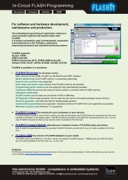
The FLASH Programming Tool<br />
for easy programming of application software in a<br />
<strong>NXP</strong> <strong>ARM</strong> <strong>Cortex</strong> <strong>M3</strong>/<strong>M0</strong> and <strong>ARM</strong>7 System<br />
11-08 Seite 1 2011-08-e-flashit-manual-<strong>NXP</strong>-04.docx
<strong>FLASHit</strong> 9- <strong>NXP</strong> <strong>ARM</strong> <strong>Cortex</strong>-<strong>M0</strong>/<strong>M3</strong>, <strong>ARM</strong>7 <strong>Manual</strong><br />
LIMITED WARRANTY!<br />
By using this <strong>FLASHit</strong> product and its associated products, you agree to the following<br />
conditions.<br />
If you are unable to agree to these conditions, please notify us within two days of<br />
purchasing <strong>FLASHit</strong>.<br />
LIMITED warranty:<br />
hse-electronics guarantees that the <strong>FLASHit</strong> product will basically work as advertised and without<br />
defects if used properly for a period of 6 months after delivery.<br />
CLAIMS of the customer:<br />
At the discretion of hse-electronics, the entire liability of hse-electronics and your sole claim shall<br />
involve either<br />
a) a refund of the paid price or<br />
b) subsequent improvement or product placement.<br />
This limited warranty does not apply if the failure of the product can be attributed to an accident or<br />
improper use.<br />
NO additional warranty:<br />
hse-electronics excludes any additional warranty claims related to the delivered product and<br />
associated manuals and written materials.<br />
NO liability for consequential damage:<br />
Neither hse-electronics nor the suppliers of hse-electronics are liable to pay compensation<br />
(included but not limited to damages for loss of profit, service interruption, loss of business<br />
information or data or any other financial loss) arising from the use of this hse-electronics product<br />
even if hse-electronics has been notified of the possibility of such damages.<br />
LIMITED liability:<br />
The liability of hse-electronics shall in any case be limited to the amount that the customer paid for<br />
the product. This exemption shall not apply to damages caused by willful intent or gross negligence<br />
on the part of hse-electronics.<br />
JURISDICTION:<br />
Disputes arising from this licensing agreement may only be resolved in the regional court of Kiel.<br />
If you have any questions about this agreement, please contact your dealer or send us an e-mail at<br />
info@hse-electronics.com.<br />
11-08 Seite 2 2011-08-e-flashit-manual-<strong>NXP</strong>-04.docx
Table of contents<br />
<strong>FLASHit</strong> 9- <strong>NXP</strong> <strong>ARM</strong> <strong>Cortex</strong>-<strong>M0</strong>/<strong>M3</strong>, <strong>ARM</strong>7 <strong>Manual</strong><br />
1 <strong>FLASHit</strong> .................................................................................................................................................................... 4<br />
1.1 <strong>FLASHit</strong> ............................................................................................................................................................. 4<br />
1.1 How does <strong>FLASHit</strong> work? ................................................................................................................................. 4<br />
2 System Requirements ............................................................................................................................................ 4<br />
3 Program-Installation and Registration ................................................................................................................. 5<br />
3.1 Installation ......................................................................................................................................................... 5<br />
3.2 Registration ....................................................................................................................................................... 5<br />
4 Program Functions ................................................................................................................................................. 6<br />
4.1 Establishing A Connection ................................................................................................................................ 6<br />
4.2 Setting the Baud Rate ....................................................................................................................................... 6<br />
4.3 <strong>FLASHit</strong> Working Directory ............................................................................................................................... 6<br />
4.4 Expert or Express Mode .................................................................................................................................... 7<br />
4.5 Uploading to the Target System ("burn FLASH") .............................................................................................. 8<br />
4.6 HEX or BIN? ...................................................................................................................................................... 9<br />
4.7 FLASH-Memory-Info ......................................................................................................................................... 9<br />
4.8 Information about supported MCUs ................................................................................................................ 10<br />
4.9 Upload into the RAM of the Target .................................................................................................................. 10<br />
4.10 Target System Info .......................................................................................................................................... 11<br />
4.11 Configuring <strong>FLASHit</strong> – Target System ............................................................................................................ 11<br />
4.12 Configuring <strong>FLASHit</strong> – Programming Sequence ............................................................................................. 12<br />
5 Special Functions ................................................................................................................................................. 14<br />
5.1 Reading Out the FLASH Memory.................................................................................................................... 14<br />
5.2 Reading Out the Content of Individual Addresses .......................................................................................... 15<br />
5.3 Build Checksum............................................................................................................................................... 15<br />
5.4 Saving the Debug Log File .............................................................................................................................. 15<br />
5.5 Generating a Software Reset .......................................................................................................................... 15<br />
5.6 Generating a Hardware Reset ......................................................................................................................... 16<br />
5.7 Command Line Functions ............................................................................................................................... 17<br />
5.8 Saving or loading the Configuration ................................................................................................................ 17<br />
6 The <strong>FLASHit</strong> Package .......................................................................................................................................... 18<br />
6.1 RS232 Terminal............................................................................................................................................... 18<br />
6.2 Checksum Builder ........................................................................................................................................... 20<br />
6.3 IO Check .......................................................................................................................................................... 21<br />
6.4 Command Line Generator (CmdLine) ............................................................................................................. 23<br />
7 Appendix ............................................................................................................................................................... 25<br />
7.1 Status Messages (Errorcodes) ........................................................................................................................ 25<br />
7.2 Supported MCUs ............................................................................................................................................. 29<br />
7.3 Overview of Command Line Functions ........................................................................................................... 30<br />
7.4 Sources of Checksum Function ...................................................................................................................... 32<br />
7.5 Reset- und Bootstrap-Signals ......................................................................................................................... 33<br />
7.6 Reset- und Bootstrap-Interface ....................................................................................................................... 33<br />
8 HEXit the HEX-File Analysis-Tool ....................................................................................................................... 34<br />
9 Project Engineering .............................................................................................................................................. 35<br />
11-08 Seite 3 2011-08-e-flashit-manual-<strong>NXP</strong>-04.docx
1 <strong>FLASHit</strong><br />
1.1 <strong>FLASHit</strong><br />
<strong>FLASHit</strong> 9- <strong>NXP</strong> <strong>ARM</strong> <strong>Cortex</strong>-<strong>M0</strong>/<strong>M3</strong>, <strong>ARM</strong>7 <strong>Manual</strong><br />
<strong>FLASHit</strong> allows you to quickly and easily program application software in a <strong>NXP</strong> <strong>ARM</strong> <strong>Cortex</strong>-<strong>M0</strong>/<strong>M3</strong>, <strong>ARM</strong>7<br />
1.1 How does <strong>FLASHit</strong> work?<br />
<strong>FLASHit</strong> was designed for easy use. Once a connection to the hardware has been established via the RS232 interface<br />
and the interface parameters have been set, you only have to select an application for the upload / programming process<br />
(burning) to the target system to begin.<br />
This process occurs as follows (without enabled options):<br />
� Automatical detection of the MCU-type<br />
� The bootstrap loaders of the target system are activated<br />
� The configuration of the target system is determined<br />
� The type of FLASH being used is detected automatically<br />
� The FLASH data are displayed<br />
� Hex file analysis:The sectors to be deleted are identified and selected and hex data are arranged in a binary array<br />
� The FLASH memory is deleted (either individual sectors or the entire chip)<br />
� FLASH in the target system is reprogrammed in blocks (programmed sectors are selected).<br />
2 System Requirements<br />
Target System<br />
MCU: <strong>NXP</strong> <strong>ARM</strong> <strong>Cortex</strong>-<strong>M0</strong>/<strong>M3</strong>, <strong>ARM</strong>7<br />
PC<br />
Operating system: All current versions of Windows<br />
Hardware: Pentium or higher<br />
11-08 Seite 4 2011-08-e-flashit-manual-<strong>NXP</strong>-04.docx
<strong>FLASHit</strong> 9- <strong>NXP</strong> <strong>ARM</strong> <strong>Cortex</strong>-<strong>M0</strong>/<strong>M3</strong>, <strong>ARM</strong>7 <strong>Manual</strong><br />
3 Program-Installation and Registration<br />
3.1 Installation<br />
If you have a CD:<br />
� Insert the program CD into the CD-ROM drive of your PC.<br />
� Follow the instructions on your screen.<br />
If you downloaded <strong>FLASHit</strong> from the hse-electronics website:<br />
� Double-click setupflashit_<strong>NXP</strong>.exe<br />
� Follow the instructions on your screen.<br />
3.2 Registration<br />
Two licensing methods are available:<br />
1. PC-based licensing<br />
2. USB dongle-based licensing<br />
When <strong>FLASHit</strong> is launched for the first time, you will need to<br />
register it in the Help/Registration menu (otherwise <strong>FLASHit</strong><br />
will run in restricted demo mode). If <strong>FLASHit</strong> was delivered with<br />
a dongle, you can skip the following steps. Insert the dongle<br />
into the USB port to unlock the program.<br />
To register <strong>FLASHit</strong>, complete the following two steps:<br />
Step 1:<br />
Perform this step on the computer you want to register <strong>FLASHit</strong><br />
for!<br />
Click Build registration data.<br />
<strong>FLASHit</strong> will generate your own personal System Id.<br />
� Fill in the fields marked with "*".<br />
� Now send us your registration data either by e-mail<br />
(Build mail...) or by fax (Print...).Once we receive the<br />
data we will send you your activation code (by e-mail or<br />
fax).<br />
Step 2:<br />
- Enter the activation code under<br />
Enter license key.<br />
- Click Enable license.<br />
- If the message License is enabled appears (in a green field),<br />
then <strong>FLASHit</strong> has been successfully registered.<br />
If you have any questions about registration, e-mail us at<br />
info@hse-electronics.com.<br />
Note: If you need a new activation code because your hardware or other conditions have changed, e-mail us the old<br />
license number and we will send you a new one.<br />
11-08 Seite 5 2011-08-e-flashit-manual-<strong>NXP</strong>-04.docx
4 Program Functions<br />
<strong>FLASHit</strong> 9- <strong>NXP</strong> <strong>ARM</strong> <strong>Cortex</strong>-<strong>M0</strong>/<strong>M3</strong>, <strong>ARM</strong>7 <strong>Manual</strong><br />
4.1 Establishing A Connection<br />
- Connect your PC to the target system via the serial interface.<br />
- Select the COM port you want to use in the Setup menu. you<br />
can choose from the first 10 installed COM devices whose<br />
COM numbers can range from 1 to 99.<br />
Note: If you are using a USB RS232 adapter, you can also run <strong>FLASHit</strong> via a USB port. All settings in bold are the<br />
default or recommended settings.<br />
4.2 Setting the Baud Rate<br />
4.3 <strong>FLASHit</strong> Working Directory<br />
The adjustable baud rate between the target system and your<br />
PC depends on, among other factors, the clock rate of the<br />
target system (divisible by a standard baud rate). Just try out<br />
different baud rates<br />
and select the one you want from the Baud rate menu<br />
<strong>FLASHit</strong> creates several files during a session:<br />
flashit.ini // program settings<br />
result.txt // return values<br />
Depending on which version of Windows is being used (in this case WinXP), these files are saved by default in the<br />
directory specified by Windows.<br />
(e. g.: c:\Documents and Settings\All Users\Applications Datas\<strong>FLASHit</strong>\*.*.)<br />
Windows must be set to allow the creation and writing of files in this directory!<br />
If you want to use a different working directory, you need to create one in advance.<br />
Proceed as follows:<br />
- Open the Properties dialog from the context menu and select the Connection tab.<br />
- Enter the following in the Target input box (example):<br />
c:\programme\flashit_<strong>NXP</strong>.exe WORK_DIR=j:\ini<br />
Result:<br />
Double-click the <strong>FLASHit</strong> icon to launch the application and the files will then be saved in the "j:\ini" directory.<br />
If the path name is enclosed in quotation marks, blank spaces are allowed (example):<br />
c:\program files\flashit_<strong>NXP</strong>.exe WORK_DIR=“c:\Program Files\<strong>FLASHit</strong>“<br />
You can check the path by selecting Work dir... from the Setup<br />
menu.<br />
11-08 Seite 6 2011-08-e-flashit-manual-<strong>NXP</strong>-04.docx
<strong>FLASHit</strong> 9- <strong>NXP</strong> <strong>ARM</strong> <strong>Cortex</strong>-<strong>M0</strong>/<strong>M3</strong>, <strong>ARM</strong>7 <strong>Manual</strong><br />
4.4 Expert or Express Mode<br />
By selecting the Expert mode and Express mode menu<br />
items in the Setup menu you can choose between a basic or<br />
advanced <strong>FLASHit</strong> user interface.<br />
<strong>FLASHit</strong> "remembers" the previous settings when restarted<br />
„Expert mode“ (Default)<br />
Basic user interface of <strong>FLASHit</strong>: "Express mode"<br />
11-08 Seite 7 2011-08-e-flashit-manual-<strong>NXP</strong>-04.docx
<strong>FLASHit</strong> 9- <strong>NXP</strong> <strong>ARM</strong> <strong>Cortex</strong>-<strong>M0</strong>/<strong>M3</strong>, <strong>ARM</strong>7 <strong>Manual</strong><br />
4.5 Uploading to the Target System ("burn FLASH")<br />
Having addressed the most important program settings in Items 4.1 and 4.2, we can now begin the process of uploading<br />
the application software to the target system.<br />
The UploadFile tab lets you select a specific file (set format<br />
filter to *.hex). Information on the file you select will appear in<br />
the File-Info window. Click the Upload box in the bottom right<br />
corner to start uploading the file to the FLASH memory.<br />
<strong>FLASHit</strong> will attempt to automate the settings described below.<br />
During the upload <strong>FLASHit</strong> switches to the FlashMem tab and<br />
displays the data of the FLASH memory being used (FLASH<br />
type, manufacturer, memory capacity and the number of<br />
sectors). The Status window shows the progress of the upload.<br />
You can cancel the upload at any time by clicking Cancel.<br />
The Status window will turn green when the upload is complete.<br />
If the Status window turns red the upload was unsuccessful.<br />
The possible causes of the upload failure can be viewed in the<br />
Status window.<br />
The appendix contains list of all error codes.<br />
Note: If <strong>FLASHit</strong> was unable to automatically reset your target system before the upload began, you will be prompted to<br />
reset the target system. To do so, you need to activate the Bootstrap mode (BOOT1 auf High). Long upload file<br />
names are shown in abbreviated form in the upper window of <strong>FLASHit</strong> for space reasons. To view the entire<br />
path, place the cursor over the panel.<br />
11-08 Seite 8 2011-08-e-flashit-manual-<strong>NXP</strong>-04.docx
4.6 HEX or BIN?<br />
<strong>FLASHit</strong> 9- <strong>NXP</strong> <strong>ARM</strong> <strong>Cortex</strong>-<strong>M0</strong>/<strong>M3</strong>, <strong>ARM</strong>7 <strong>Manual</strong><br />
<strong>FLASHit</strong> allows you to write Intel-HEX files (*.hex) as well as Motorola-HEX-files (*.s19) and binary files to the FLASH<br />
memory of the target system.<br />
To do so, click the Program file into flash>Load Bin option in<br />
the Config>Target and program configuration menu. With<br />
this setting <strong>FLASHit</strong> will no longer interpret the file to be saved<br />
in FLASH. Even HEX files will not (!) be treated as HEX-files,<br />
but as binary files!<br />
The start address in the target system where you want to save<br />
the binary file can also be set there.<br />
If the Program file into flash/Load Hex option is enabled, you will not be able to flash binary files since they do not have<br />
the same structure as Intel hex files.<br />
If the Program file into flash/Load Bin option is enabled and a hex file is selected to be flashed, <strong>FLASHit</strong> will ask you to<br />
confirm your selection again.<br />
4.7 FLASH-Memory-Info<br />
Regardless of whether or not an upload has been initiated, you can press the Analysis button on the FlashMem tab to<br />
display the following information on the FLASH type being used:<br />
- MCU type<br />
- Producer<br />
- Memory size<br />
- Number of sectors<br />
- Place of the FLASH memory<br />
- FLASH code<br />
- Partitioning and size of the individual sectors<br />
<strong>FLASHit</strong> automatically detects the MCU-type being used. A<br />
summary of the currently supported MCU- types can be found<br />
in the Flash types menu item of the Help menu.<br />
You can also view all supported MCU-Types on our website at<br />
www.hse-electronics.com.<br />
Regardless of whether a program is being uploaded, you can<br />
use the Chip Erase option to delete the entire FLASH memory<br />
chip or the Sector Erase option to delete individual sectors of<br />
the FLASH memory by selecting them with the mouse.<br />
11-08 Seite 9 2011-08-e-flashit-manual-<strong>NXP</strong>-04.docx
<strong>FLASHit</strong> 9- <strong>NXP</strong> <strong>ARM</strong> <strong>Cortex</strong>-<strong>M0</strong>/<strong>M3</strong>, <strong>ARM</strong>7 <strong>Manual</strong><br />
4.8 Information about supported MCUs<br />
4.9 Upload into the RAM of the Target<br />
The Help>Flash types... menu lets you view the entire MCU<br />
database of <strong>FLASHit</strong>. If the particular MCU you want is not<br />
listed, hse may be able to quickly import the relevant software<br />
component.<br />
With this function <strong>FLASHit</strong> also offers help in searching for<br />
supported MCU types.<br />
You can enter keywords for the search in the View Filter menu<br />
(manufacturer, name and FLASH size).<br />
All sectors of the FLASH are graphically represented. If you<br />
select a sector with the mouse, the number, size and start and<br />
end address of that sector will be shown.<br />
With the RAM Upload function you can transfer the content of a<br />
file to the RAM of the target system. Both the Intel hex and<br />
binary file formats are supported.<br />
Select the RAM Upload file in the File>Upload file into RAM<br />
dialog. This file is selected independently of the FLASH Upload<br />
file selection. The Base address and Top address panels<br />
show the corresponding data of the Upload file. You may have<br />
to adjust the base address depending on the target system.<br />
You can enter a new base address in the User defined field<br />
and the top address will then be automatically recalculated<br />
(Top address).<br />
In this example the basis address of the Upload file is<br />
0x20000200. A new basis address, 0x20000000, is specified in<br />
the User defined field so that the data can be placed in the<br />
RAM.<br />
11-08 Seite 10 2011-08-e-flashit-manual-<strong>NXP</strong>-04.docx
4.10 Target System Info<br />
<strong>FLASHit</strong> 9- <strong>NXP</strong> <strong>ARM</strong> <strong>Cortex</strong>-<strong>M0</strong>/<strong>M3</strong>, <strong>ARM</strong>7 <strong>Manual</strong><br />
Click the Get info button to see information about the target system on the Target CPU tab.<br />
4.11 Configuring <strong>FLASHit</strong> – Target System<br />
Processor: Target CPU type<br />
RAM: Size of the RAM of the MCU<br />
FLASH: Size of the FLASH of the MCU<br />
Bootloader: Version of the internal bootloader<br />
MANUF: Manufacturer<br />
IDCHIP: MCU ID code<br />
Device ID(H): Unique device ID register (96 bits)<br />
Device ID(L): Unique device ID register (96 bits)<br />
FLASH content: the first 24 bytes of the FLASH memory is<br />
displayed.<br />
Although <strong>FLASHit</strong> determines most of the required data on its own, a number of parameters may have to be set<br />
manually.<br />
You can configure the various settings of the target system<br />
using the Config>Target and program configuration menu<br />
and the Target System tab.<br />
Target CPU<br />
<strong>FLASHit</strong> normally detects the target CPU automatically.<br />
If you select the Target Reset>Automatic option, <strong>FLASHit</strong> will<br />
try to reset the target system automatically.<br />
If the User defined option is selected, you will be able to define<br />
the reset behavior of <strong>FLASHit</strong> (Define) manually.<br />
Flash memory<br />
<strong>FLASHit</strong> currently supports in this version only the internal<br />
OnChipFLASH-Memorys of the <strong>NXP</strong> MCU<br />
Basic address:<br />
The basic address of the FLASH memory defines the address<br />
that <strong>FLASHit</strong> uses for the FLASH memory. This address is<br />
normally= 0x08000000<br />
11-08 Seite 11 2011-08-e-flashit-manual-<strong>NXP</strong>-04.docx
<strong>FLASHit</strong> 9- <strong>NXP</strong> <strong>ARM</strong> <strong>Cortex</strong>-<strong>M0</strong>/<strong>M3</strong>, <strong>ARM</strong>7 <strong>Manual</strong><br />
4.12 Configuring <strong>FLASHit</strong> – Programming Sequence<br />
You can configure the programming sequence settings using the Config>Target and program configuration menu and<br />
the Program sequence tab. <strong>FLASHit</strong> performs parameter 0p through 8 in sequential order. The parameters highlighted<br />
in bold in the Configuration window are default settings.<br />
0p. Clear protection<br />
With the option Clear protection the possibility exists to<br />
deactivate Readout and or Writingprotection<br />
With the deactivation of the Readoutprotection the hole<br />
FLASHmemory will be erased!<br />
0r. Ram Upload<br />
A chosen file is loaded into the internal RAM of the MCU with<br />
the option Ram Upload.<br />
1. Erasing Flash<br />
In this panel you can select either Chip Erase mode (the<br />
FLASH memory is completely erased before downloading) or<br />
Sector Erase mode. In Sector-Erase mode <strong>FLASHit</strong> analyses<br />
the Intel hex file that you want to upload to the target system<br />
and erases only those sectors where the program is to be<br />
saved. If the Erase Flash option is not selected, the FLASH<br />
memory will not be deleted before downloading. This is<br />
recommended if you plan on saving multiple hex files in a row.<br />
If the Ask before erase check box is selected, you will be<br />
asked to confirm the deletion of the FLASH memory.<br />
2. Programming file into flash<br />
This option must be selected if you want to transfer a file into<br />
the FLASH memory of the target system.<br />
<strong>FLASHit</strong> allows you to write HEX files (*.hex / *s19) as well as<br />
binary files to the FLASH memory of the target system.<br />
To do so, click the Program file into flash>Load Bin option in the Config>Target and program configuration menu.<br />
With this setting <strong>FLASHit</strong> will no longer interpret the file to be saved in FLASH. Even Intel hex files will not (!) be treated<br />
as hex files, but as binary files! With this option you can "flash" data from a target system (or bitmaps, text files, etc.) into<br />
another target system.<br />
The target system's start address where the binary file is to be saved can also be defined in this menu.<br />
3a. Build checksum (CRC)<br />
Select the Build Checksum option and <strong>FLASHit</strong> will build a checksum based on the content of the FLASH memory.<br />
In the "Calculation area of checksum" section you can specify the address spaces to be used in building the checksum.<br />
The red area, for example, shows a space that contains the SFR or RAM and will therefore be hidden.<br />
ADD32 (Add Bytes) requires about 2 Sec/256 Kbyte (lowest security level).<br />
CRC16 (Cyclic Redundancy Check) requires about 16 Sec/256 Kbyte (highest security level). Since the system area is<br />
located in the linear address space (red field), it must be hidden during the checksum building process. You can specify<br />
the system area here.<br />
Note: The procedures described in this section are illustrated in Appendix 7.4, Sources of the Checksum Functions.<br />
3b. Compare checksum with<br />
Compares a fixed checksum with the calculated checksum or a checksum created from the upload file. You can also<br />
perform a checksum check of a specific area of the upload file (Upload file area).<br />
11-08 Seite 12 2011-08-e-flashit-manual-<strong>NXP</strong>-04.docx
<strong>FLASHit</strong> 9- <strong>NXP</strong> <strong>ARM</strong> <strong>Cortex</strong>-<strong>M0</strong>/<strong>M3</strong>, <strong>ARM</strong>7 <strong>Manual</strong><br />
4. Write dword (32Bit)<br />
Selecting this option allows you to write a "dword" (4 bytes) in<br />
the variable address of the FLASH memory. The selected<br />
address of the FLASH memory must have been deleted before<br />
the word can be written.<br />
5a. Write User serial number into flash<br />
This option causes <strong>FLASHit</strong> to automatically generate a serial<br />
number and save it at a specified address (At address). The<br />
Prefix and Number input fields determine how the serial<br />
number will look like. The Increment... option specifies whether<br />
the Number field will be increased by 1 (incremented) each time<br />
the serial number is saved successfully. The two preview fields<br />
show how the following numbers will look like. If you select the<br />
Write number into logfile option, all assigned serial numbers<br />
will be saved in a log file. The name of the log file is composed<br />
of the prefix of the serial number and the *.txt extension (e.g.,<br />
hse1.txt).<br />
5b.Increment number after successful writing<br />
5c. Write number into logfile<br />
Sp .Set protection.<br />
With the option Setprotection the possibility exists to activate<br />
Readout and or Writingprotection. With Select Sector the<br />
sectors to be protected, for Writeprotection can be selected.<br />
6. Reset target<br />
The Software reset option generates a software reset in the target system once the download is complete. When the<br />
Hardware reset option is selected, <strong>FLASHit</strong> will generate a "bootstrap signal" on the DTR line of the COM interface and<br />
"reset signal" on the RTS line (see 7.5). This option allows you to reset the target system and switch to bootstrap mode<br />
provided that such a mode is recognized on the target hardware (see 7.5 and 7.6).<br />
7. Start RS232 Terminal<br />
Select the Start RS232 Terminal option to start a terminal program after the target system is reset that displays all the<br />
data your application transferred over the RS232 interface (the correct baud rate must be set!):<br />
Rx term Minimal terminal program in status window<br />
Smal term External terminal program (hse tool)<br />
Ext. term External terminal program<br />
8. Exit <strong>FLASHit</strong> after upload sequence<br />
With this option you can specify whether and in what way <strong>FLASHit</strong> will automatically quit after an upload.<br />
Saving or loading Configuration Data<br />
In the File>Open configuration menu you can load previously<br />
saved settings, saved them with Save configuration or save<br />
them under a new name with Save configuration as...<br />
11-08 Seite 13 2011-08-e-flashit-manual-<strong>NXP</strong>-04.docx
5 Special Functions<br />
<strong>FLASHit</strong> 9- <strong>NXP</strong> <strong>ARM</strong> <strong>Cortex</strong>-<strong>M0</strong>/<strong>M3</strong>, <strong>ARM</strong>7 <strong>Manual</strong><br />
<strong>FLASHit</strong> provides an array of additional tools in the Special Functions menu item.<br />
5.1 Reading Out the FLASH Memory<br />
Reads out the FLASH memory and saves it as either a *.bin or<br />
*.hex file.<br />
Size:<br />
Displays the size of the FLASH memory<br />
top address:<br />
Shows the top memory address of the selected FLASH<br />
memory.<br />
end address<br />
End address of reading<br />
start address:<br />
Start address of reading<br />
11-08 Seite 14 2011-08-e-flashit-manual-<strong>NXP</strong>-04.docx
<strong>FLASHit</strong> 9- <strong>NXP</strong> <strong>ARM</strong> <strong>Cortex</strong>-<strong>M0</strong>/<strong>M3</strong>, <strong>ARM</strong>7 <strong>Manual</strong><br />
5.2 Reading Out the Content of Individual Addresses<br />
5.3 Build Checksum<br />
5.4 Saving the Debug Log File<br />
5.5 Generating a Software Reset<br />
Click the Target-memory viewer menu item to read out the<br />
individual addresses from the FLASH module.<br />
If the add address by 16 check box is selected, every time you<br />
click the Read from target button the subsequent bytes will be<br />
displayed.<br />
Click Erase view window to erase the data being displayed<br />
(but not the data in the FLASH memory!).<br />
Based on the settings you selected in the Program sequence<br />
tab of the Config>Target and program configuration menu,<br />
you can click this menu item to determine the correct<br />
checksum.<br />
<strong>FLASHit</strong> logs "debug info" during the course of a session. If an<br />
error occurs, the log data are automatically saved in the<br />
debugmemo.txt file when you quit <strong>FLASHit</strong>.<br />
If you click Save debug logfile as from the Special Function<br />
menu, the logged data will be saved in the directory of your<br />
choosing (for cases where no errors occur). This log file is used<br />
to perform a precise error analysis.<br />
This option is a software command (SRST) that can be used to<br />
generate a reset in the target system. (Go_CMD)<br />
Note: The software reset cannot be used to contact (boot) the target system! It can only start an application in the target<br />
system after the upload.<br />
11-08 Seite 15 2011-08-e-flashit-manual-<strong>NXP</strong>-04.docx
<strong>FLASHit</strong> 9- <strong>NXP</strong> <strong>ARM</strong> <strong>Cortex</strong>-<strong>M0</strong>/<strong>M3</strong>, <strong>ARM</strong>7 <strong>Manual</strong><br />
5.6 Generating a Hardware Reset<br />
When the Generate hardware reset... option is selected,<br />
<strong>FLASHit</strong> will generate a "bootstrap signal" on the DTR line of<br />
the COM interface and a "reset signal" on the RTS line (see<br />
7.5). This option allows you to reset the target system and<br />
switch to bootstrap mode provided that such a mode is<br />
recognized on the target hardware (see 7.5 and 7.6).<br />
The form of the reset impulse can be adjusted in the Hardware<br />
Reset dialog.<br />
The settings you make here do not affect the automatic reset<br />
mechanism of <strong>FLASHit</strong>.<br />
11-08 Seite 16 2011-08-e-flashit-manual-<strong>NXP</strong>-04.docx
<strong>FLASHit</strong> 9- <strong>NXP</strong> <strong>ARM</strong> <strong>Cortex</strong>-<strong>M0</strong>/<strong>M3</strong>, <strong>ARM</strong>7 <strong>Manual</strong><br />
5.7 Command Line Functions<br />
The functionality of <strong>FLASHit</strong> can be controlled externally by means of command line parameters (scripts). Note that these<br />
parameters are upper and lower case sensitive! The CmdLine tool (see 6.4 Command Line Generator CmdLine) can be<br />
used automatically generate the appropriate scripts. Command lines allow you to access and control <strong>FLASHit</strong> from a<br />
separate application with or without the desktop user interface.<br />
Example:<br />
1. <strong>FLASHit</strong> is to be launched via an icon on the Windows desktop.<br />
2. A specific file is to be loaded.<br />
3. The baud rate and the COM port are to be specified.<br />
4. The file is to be programmed into the FLASH memory of the target system.<br />
5. <strong>FLASHit</strong> exits automatically once the upload is complete.<br />
Proceed as follows:<br />
- Create a new <strong>FLASHit</strong> shortcut on the Windows desktop.<br />
- Give the icon a name (e.g., out.hex).<br />
- Open the Properties dialog from the context menu and select the Connection tab.<br />
- Enter the following in the Target input box:<br />
c:\programme\flashit_<strong>NXP</strong>.exe COM=1 BAUD=57600 HEX-FILE=e:\projekt\out.hex AUTOSTART EXIT<br />
Result:<br />
Double-click the out.hex program icon to launch <strong>FLASHit</strong> and the e:\projekt\out.hex file is transferred via COM1 at<br />
a baud rate of 57.600 to the target system where it is then programmed in the FLASH memory. <strong>FLASHit</strong> exits<br />
automatically.<br />
Note: Chapter 7.2 provides an overview of the command line functions.<br />
Priorities in the <strong>FLASHit</strong> Configuration<br />
Alle vorgenommenen Parameter-Einstellungen (z. B. Baudrate, COM-Port usw.) von <strong>FLASHit</strong> werden in der Datei<br />
flashit_<strong>NXP</strong>.ini abgespeichert.<br />
5.8 Saving or loading the Configuration<br />
All the parameters you set (e.g., baud rate, COM port, etc.) in<br />
<strong>FLASHit</strong> are stored in the flashit_<strong>NXP</strong>.ini file.<br />
Each valid <strong>FLASHit</strong> parameter (Actual-Config) is composed of:<br />
- the "old data" from the flashit_<strong>NXP</strong>.ini file.<br />
(Old-Config)<br />
- any "parameters" that are transferred when <strong>FLASHit</strong> starts up,<br />
for example, from another program (Command-Line-Config).<br />
These parameters have priority over the parameters saved in<br />
the flashit_<strong>NXP</strong>.ini file.<br />
- the settings made by <strong>FLASHit</strong> directly on the desktop<br />
(Desktop-Config); these settings have priority over all other<br />
parameters.<br />
Select Save configuration to save all the settings you have<br />
made.<br />
Select Open configuration... to load the settings.<br />
11-08 Seite 17 2011-08-e-flashit-manual-<strong>NXP</strong>-04.docx
<strong>FLASHit</strong> 9- <strong>NXP</strong> <strong>ARM</strong> <strong>Cortex</strong>-<strong>M0</strong>/<strong>M3</strong>, <strong>ARM</strong>7 <strong>Manual</strong><br />
6 The <strong>FLASHit</strong> Package<br />
The tools described below are part of the <strong>FLASHit</strong> package and represent stand-alone programs that can be loaded<br />
externally or directly in <strong>FLASHit</strong>.<br />
6.1 RS232 Terminal<br />
The RS232 terminal is a universal terminal program for logging<br />
data sent by the application on the target system via the RS232<br />
interface.<br />
Note: RS232 terminal can be launched either separately or in<br />
<strong>FLASHit</strong>.<br />
You can start all of the standard functions in the File menu.<br />
You can set the display mode in the Display menu.<br />
Hex format:<br />
All data are displayed in the hex format.<br />
ASCII format<br />
All data are displayed in the ASCII format.<br />
Hex+ASCII format:<br />
All data are displayed in the ASCII and hex formats.<br />
Transmit:<br />
In the Transmit list box you can select the string you want to<br />
send. Click the Transmit button to send the string via the<br />
RS232 interface.<br />
Tx window:<br />
Click the TX window button to open a window where any text<br />
you enter will be sent "live" via the RS232 interface.<br />
11-08 Seite 18 2011-08-e-flashit-manual-<strong>NXP</strong>-04.docx
<strong>FLASHit</strong> 9- <strong>NXP</strong> <strong>ARM</strong> <strong>Cortex</strong>-<strong>M0</strong>/<strong>M3</strong>, <strong>ARM</strong>7 <strong>Manual</strong><br />
Click Clear Rx-Window to erase all data in the receive window.<br />
You can set the COM connection mode in the Connected<br />
menu.<br />
The Line feed menu lets you adjust the line feed of the data in the terminal window, as well as define separate line<br />
breaks for receive and transmit.<br />
Line feed at CR:<br />
Line feed at a carriage return.<br />
Line feed at LF:<br />
Line feed at a line feed.<br />
Line feed at traffic break:<br />
Line feed when data are absent<br />
Add CR:<br />
Adds a carriage return to the sent text.<br />
Add LF:<br />
Adds a line feed to the sent text.<br />
Add CR+LF:<br />
Adds a carriage return and a line feed to the sent text.<br />
Add none:<br />
Does not add a carriage return or a line feed to the sent text.<br />
You can configure the standard COM port settings in the Setup<br />
menu.<br />
Target Reset via Terminal<br />
The Control target menu can be used to generate a hardware<br />
reset of the target system. Before this can be done, however,<br />
the relevant connections of the RS232 interface must be wired<br />
based on the circuit suggestion (see Appendix 7.6, Reset and<br />
Bootstrap Interface).<br />
11-08 Seite 19 2011-08-e-flashit-manual-<strong>NXP</strong>-04.docx
6.2 Checksum Builder<br />
<strong>FLASHit</strong> 9- <strong>NXP</strong> <strong>ARM</strong> <strong>Cortex</strong>-<strong>M0</strong>/<strong>M3</strong>, <strong>ARM</strong>7 <strong>Manual</strong><br />
The checksum builder is a universal program for calculating the checksum of a hex file.<br />
Hex-File = j:\hexfiles\128kRandom.hex<br />
CRC16 = 0x51EF<br />
ADD32 = 0x00EDFE42l<br />
Error Code = 000<br />
Start-Adr = 0x000000<br />
BegInt-Adr = 0x00E000<br />
EndInt-Adr = 0x00FFFF<br />
End-Adr = 0x01FFFF<br />
Error code Meaning<br />
0 Error-free execution.<br />
14 Unable to read file.<br />
36 The size of the flash module is unknown.<br />
171 The file contains data outside of flash.<br />
175 File not found<br />
You can select a hex file in the File menu. In the FLASH size<br />
list box you can specify the size of the FLASH memory.<br />
The checksum builder defines the start and end addresses<br />
based on the FLASH size setting. You only need to specify the<br />
internal area of the target controller in the Begin of internal<br />
area und End of internal area fields since this area is factored<br />
out when calculating the checksum.<br />
Click Calculate to start the calculation.<br />
The resulting checksum will be indicated by the ADD32 and<br />
CRC16 values.<br />
Note: The checksum builder can only be launched externally.<br />
You can control the Checksum Builder using command line<br />
parameters.<br />
Command Function<br />
EXIT The program exits after the calculation.<br />
A1= Defines the start address of the checksum calculation.<br />
A2= Defines the start address of the system area.<br />
A3= Defines the end address of the system area.<br />
A4= Defines the end address of the checksum calculation.<br />
FS= Defines the flash size (0=auto, 1=64 k, 2=128 k, 3=256 k,<br />
4=512 k, 5=1 M, 6=2 M, 7=4 M)<br />
FP= Defines the data content of a deleted flash module (fill<br />
pattern).<br />
HEX-FILE= Defines the file the checksum builder calculates.<br />
LOCAL= The result file is written to the program directory.<br />
A result file (Result_CRC.txt) will be created when you exit<br />
the checksum builder. The file is located at<br />
C:\Doku..Einstellungen\All users\Anwendungsdaten\Flashit<br />
in Windows XP and C:\PrgramData\<strong>FLASHit</strong> in Windows Vista.<br />
Example of Result_CRC.txt<br />
The checksum builder sends a return code back to the calling<br />
program. The return code is divided into two areas: the CRC17<br />
checksum (Bit 0..15) and the error code (Bit 16..31).<br />
11-08 Seite 20 2011-08-e-flashit-manual-<strong>NXP</strong>-04.docx
6.3 IO Check<br />
<strong>FLASHit</strong> 9- <strong>NXP</strong> <strong>ARM</strong> <strong>Cortex</strong>-<strong>M0</strong>/<strong>M3</strong>, <strong>ARM</strong>7 <strong>Manual</strong><br />
The IO check is an interface testing tool that is integrated in the <strong>FLASHit</strong> package and is used to check whether the COM<br />
port (the basis for working with <strong>FLASHit</strong>) is functioning properly.<br />
Note: IO check can be launched either separately or in <strong>FLASHit</strong>.<br />
When the IO check function is executed, all installed COM parts<br />
will be checked to determine whether access via the Windows<br />
API function (API=Application Programming Interface) is<br />
possible. Afterwards the direct access to the PIO module (PIO<br />
mode) will be checked.<br />
IO check shows which COM ports can be used in <strong>FLASHit</strong>.<br />
<strong>FLASHit</strong> can only use COM ports that are accessible via the<br />
API.<br />
IO check also lets you manually enable and disable individual<br />
port lines and test the LPT1port.<br />
Access modes<br />
Access to the COM port via the API is only possible if the port<br />
was free prior to starting the program.<br />
The PIO mode is perfect for "observation" while the API mode is<br />
suited to performing function tests. The PIO mode can only be<br />
used for standard COM ports, which excludes COM ports<br />
based on UBS interfaces, for example (USB RS232 Adapter).<br />
Loop test/line test:<br />
Click the Test button to open a log window that displays the<br />
results of the automatic test.<br />
To save the test results, click Save protocol as... in the File<br />
menu.<br />
A physical test of the individual lines and signal runtimes will be<br />
performed.<br />
To complete this test, however, you first need to insert a test<br />
plug into the COM port (see bottom left corner).<br />
Example for line test log:<br />
COM1: Start Loop Test (API mode)<br />
TxD -> RxD Loop ok. Delay = 1.6 ms<br />
DTR -> DSR Loop ok. Delay = 5.6 ms<br />
DTR -> DCD Loop ok. Delay = 0.9 ms<br />
RTS -> CTS Loop ok. Delay = 4.4 ms<br />
RTS -> Ri Loop ok. Delay = 0.5 ms<br />
The specified times are approximate values and depend on the<br />
speed of your computer. Signal times can be significantly longer<br />
with COM ports that are operated using a USB interface<br />
adaptor.<br />
11-08 Seite 21 2011-08-e-flashit-manual-<strong>NXP</strong>-04.docx
<strong>FLASHit</strong> 9- <strong>NXP</strong> <strong>ARM</strong> <strong>Cortex</strong>-<strong>M0</strong>/<strong>M3</strong>, <strong>ARM</strong>7 <strong>Manual</strong><br />
<strong>Manual</strong> check of port lines<br />
- signals (input)<br />
The colors of the symbol indicate the logical level. This means<br />
the logical level of "1" can range from approx. +5 V to approx.<br />
+12 V depending on the computer model. The corresponding<br />
negative level: approx. –5 V to approx. –12 V.<br />
- outputs<br />
By clicking the symbol, you can set a signal to the<br />
appropriate port.<br />
The logical level is shown in place of the exact voltage.<br />
WARNING: Any modification to the outputs may result in the destruction of hardware<br />
(PC and/or externally connected devices)!<br />
Control Lines of the Printer Connection<br />
The control lines of the first default printer (address 0x378) can be modified and monitored manually.<br />
WARNING: Any modification to the outputs may result in the destruction of hardware<br />
(PC and/or externally connected devices)!<br />
11-08 Seite 22 2011-08-e-flashit-manual-<strong>NXP</strong>-04.docx
<strong>FLASHit</strong> 9- <strong>NXP</strong> <strong>ARM</strong> <strong>Cortex</strong>-<strong>M0</strong>/<strong>M3</strong>, <strong>ARM</strong>7 <strong>Manual</strong><br />
6.4 Command Line Generator (CmdLine)<br />
To facilitate the use of command line functions in <strong>FLASHit</strong>, the CmdLine program is included on the CD and can be used<br />
to automatically generate<br />
- a command line and an ICON<br />
- a C source code (for access from a separate application)<br />
Note: The CmdLine can only be launched externally.<br />
This window makes it extremely easy to adjust the various settings. In the example here, the upload hex file (HEX-<br />
FILE=J:\Hexfiles\canopen.hex) has been selected which<br />
initiates the automatic start of the upload (AUTOSTART)<br />
sets the FLASH memory erase mode to "Sector Erase" (ERASE MODE=SECTOR)<br />
specifies that <strong>FLASHit</strong> will exit automatically (EXIT)<br />
uses the COM port (COM=1)<br />
sets the baud rate (Baud=57600)<br />
The menus highlighted in bold contain settings that have been changed.<br />
The sequence of the individual commands has no effect!<br />
This button lets you launch <strong>FLASHit</strong> directly from the specified command line.<br />
This button lets you create shortcuts with <strong>FLASHit</strong> and the specified command line.<br />
This button lets you access <strong>FLASHit</strong> from a Visual C++ code.<br />
This button lets you access <strong>FLASHit</strong> from a Borland C code.<br />
11-08 Seite 23 2011-08-e-flashit-manual-<strong>NXP</strong>-04.docx
<strong>FLASHit</strong> 9- <strong>NXP</strong> <strong>ARM</strong> <strong>Cortex</strong>-<strong>M0</strong>/<strong>M3</strong>, <strong>ARM</strong>7 <strong>Manual</strong><br />
<strong>FLASHit</strong> returns the "return code" which is then displayed by CmdLine.<br />
With the following program lines you can extract the "error code" from the return value (see 7.1).<br />
uiErrorCode = (unsigned int) ( ulReturnValue >> 8 );<br />
With the following program lines you can extract the "short code" from the return value.<br />
cShortCode = (char)( ulReturnValue & 0x0F );<br />
Short code equals bit 4 from the return value as shown below.<br />
0 No error<br />
1 Error in hex file<br />
2 Error in target system<br />
3 Flash was not found<br />
4 Flash type not supported as yet<br />
5 Error while deleting the flash module<br />
6 Error while programming the flash module<br />
7 Checksum error<br />
8 Error in program flow of <strong>FLASHit</strong><br />
other error in Windows<br />
<strong>FLASHit</strong> can also generate a "return code file" (result.txt) for evaluation by another application.<br />
Note: If you want to work with CmdLine, then it must be located in the <strong>FLASHit</strong> directory!<br />
Subject to change!<br />
"We hope your work is a success"<br />
The hse-electronics Team<br />
11-08 Seite 24 2011-08-e-flashit-manual-<strong>NXP</strong>-04.docx
7 Appendix<br />
<strong>FLASHit</strong> 9- <strong>NXP</strong> <strong>ARM</strong> <strong>Cortex</strong>-<strong>M0</strong>/<strong>M3</strong>, <strong>ARM</strong>7 <strong>Manual</strong><br />
7.1 Status Messages (Errorcodes)<br />
Versions<br />
<strong>ARM</strong><br />
<strong>Cortex</strong> <strong>M3</strong><br />
Error Number<br />
Smal return<br />
Code<br />
Message<br />
File, Modul, Libarys Not found<br />
E010 8 E010: Can't find file: *.mod<br />
E011 8 E011: Modul file was not found<br />
Ѵ E014 1 E014: Can't open upload file<br />
Ѵ E015 8 E015: No FLASH data found<br />
Ѵ E016 E016: Can't generate Binray-Temp-File<br />
Ѵ E017 E017: Can't open Binray-Temp-File<br />
Ѵ E018 E018: Can't generate Binray-File<br />
Ѵ E019 E019: Can't generate Intel-hex-file<br />
E020 8 E020: Library unit not found<br />
E023 E023: Wrong in flashitx.lib<br />
Ѵ E024 E024: Instruction file not found<br />
Ѵ E025 E025: Data base FLASHdat.LIB not found<br />
Ѵ E026 E026: Ini-File is write protected<br />
Programmcycle<br />
E030 8 E030: Modul-file is too big!<br />
Ѵ E031 8 E031: No memory for FlashLib<br />
Ѵ E032 8 E032: Not enough memory<br />
Ѵ E033 1 E033: Error in Hex-File: Line is too long!<br />
Ѵ E034 1 E034: Wrong file format. Function abort<br />
Ѵ E035 8 E035: Write mode n unknown<br />
Ѵ E036 1 E036: Size of FLASH is unknown. Abort<br />
Ѵ E038 6<br />
E038: Can't write User-Serial-Number [..] at log. address<br />
...<br />
Ѵ E039 1 E039: Mirror address is unknown<br />
Modul-File not found<br />
Modul nicht gefunden<br />
File is missing<br />
Datei fehlt<br />
Description<br />
Beschreibung<br />
Access to upload file is not possible<br />
Der Upload file konnte nicht geöffnet werden<br />
FLASH data missing<br />
Es fehlen Daten zum Flashen<br />
Access to temp file (readout.bin) not possible<br />
Temporäre Datei readout.bin konnte nicht erstellt werden<br />
Read access to temp file not possible<br />
Temporäre Datei readout.bin konnte nicht geöffnet werden<br />
Access to bin file not possible<br />
Binäre-Ziel-Datei konnte nicht geöffnet werden<br />
Access to hex file not possible<br />
Intel-Hex-Ziel-Datei konnte nicht geöffnet werden<br />
<strong>FLASHit</strong>x.lib not found<br />
Flashit.lib konnte nicht geöffnet werden.<br />
Error in Library x<br />
Fehler in Bibliothek x<br />
PDF files not found<br />
Die Datei doku/Anleitung.pdf fehlt<br />
File FLASHdat.LIB not found<br />
Die Datei FlashDat.lib wurde nicht gefunden<br />
Flashit.ini is write protection<br />
Die Ini-Datei ist schreibgeschützt<br />
File size is too big.<br />
Ein Modul ist zu groß<br />
No memory to read Flashitx.lib<br />
Kein dynamischer Speicher verfügbar um Flashdat.lib zu<br />
laden<br />
No memory to read Flashitx.lib<br />
Kein Speicher für das virtuelles Flash<br />
Hex format error<br />
Aktuelle Zeile im Intel-Hex-File ist zu lang<br />
Hex format error<br />
Unbekanntes Datenformat der Hex-Datei<br />
Flash write mode is not supported<br />
Flash-Write-Methode unbekannt<br />
Size of embedded flash is not found<br />
Größe des Flashspeichers ist unbekannt<br />
Error in embedded flash.<br />
User-Serial-Number konnte nicht geschrieben werden.<br />
Undefined size of embedded flash<br />
Größe des Flashspeichers ist unbekannt<br />
11-08 Seite 25 2011-08-e-flashit-manual-<strong>NXP</strong>-04.docx
<strong>FLASHit</strong> 9- <strong>NXP</strong> <strong>ARM</strong> <strong>Cortex</strong>-<strong>M0</strong>/<strong>M3</strong>, <strong>ARM</strong>7 <strong>Manual</strong><br />
Not supported<br />
Ѵ E040 8 E040: Sorry this CPU is not enabled at your version<br />
Ѵ E042 E042: Internal error call hse<br />
Ѵ E043 E043: Wrong Date (1)<br />
Ѵ E046 8 E046: Please contact hse-elctronics<br />
Ѵ E047 8 E047: Function in demo not available<br />
Ѵ E048 8 E048: Contact hse-elctronic<br />
Dataformat Error<br />
E051 8 E051: Try to write odd number of data!<br />
Ѵ E052 1 E052: Upload-file is no Intel-Hex format!<br />
Ѵ E053 1 E053: Overwrite Address<br />
Ѵ E056 E056: Data outside of FLASH at Address x<br />
Ѵ E058 1 E058: Checksum error in Hexfile line<br />
Ѵ E059 1 E059: Wrong blocklenght in Hexfile line<br />
E060<br />
E060: No Debug/Toolstick Adapter found<br />
Target Error<br />
E101 2 E101: Can't load modul<br />
E102 2 E102: Booting was not possible %d<br />
E103 2 E103: No correct answer from target<br />
Ѵ E104 2 E104: Communication with target failed<br />
E109 2 E109: Target-bus length unknown!<br />
Ѵ E110 2 E110: Target crashed - rebooting...<br />
Ѵ E111 2 E111: No response from target<br />
Ѵ E113 2 E113: Can't analyse contents of target FLASH<br />
E114 2 E114: Can't load buffer<br />
E116 3 E116: FLASH-Read-Test failt<br />
Target CPU (step) is unknown<br />
CPU nicht freigeschaltet (nur bei limitierter Version)<br />
<strong>FLASHit</strong> access error<br />
Interner Fehler<br />
Date is out of format<br />
Datum kann nicht korrekt ermittelt werden.<br />
User access error<br />
Fehler der eine Kontaktaufnahme zu hse erforderlich macht<br />
Licence restriction<br />
Funktion ist in der Demoversion nicht verfügbar.<br />
Upload data access error<br />
Fehler der eine Kontaktaufnahme zu hse erforderlich macht<br />
Try to write odd number of data<br />
Es wird versucht eine ungerade Anzahl von Bytes zu<br />
schreiben.<br />
Upload file format error<br />
Die Upload-Datei entspricht nicht dem Intel-Hex Format<br />
Multiple define of data in Embedded upload file<br />
Fehler im Hexfile<br />
Address of embedded file is out of FLASH memory<br />
Daten außerhalb des Speicherbereiches<br />
Checksum error in Hexfile line<br />
Prüfsummenfehler in Hexfile Zeile<br />
Wrong blocklenght in Hexfile line<br />
Anzahl der Daten stimmt nicht mit Länge der Hex-Zeile<br />
überein<br />
No Debug/Toolstick Adapter found<br />
Toolstickadapter nicht gefunden<br />
Can't load modul<br />
Fehler beim Laden eines Moduls ins Target<br />
Target booting was not possible<br />
Target konnte nicht gebootet werden<br />
Target does not answer correct<br />
Das Target antwortet nicht korrekt.<br />
Target gives an unknown response<br />
Das Taget meldet eine unbekannte CPU-Kennung.<br />
Unknown bus mode<br />
Busbreite des Target-Systems konnte nicht erkannt werden<br />
Target crashed while erasing<br />
Target ist beim Sektor-Löschen abgestürtzt und wird neu<br />
gestartet.<br />
Target does not answer correct<br />
Target antwortet nicht richtig<br />
Can't analyse contents of target FLASH<br />
Die Analyse des Inhaltes des Target Flashes war nicht<br />
möglich.<br />
Can't load buffer<br />
Ein Bufferinhalt konnte nicht ins Target geladen werden<br />
FLASH-Read-Test failt<br />
Der Flash-Lese-Test ergab ein ungültiges Ergebnis<br />
11-08 Seite 26 2011-08-e-flashit-manual-<strong>NXP</strong>-04.docx
<strong>FLASHit</strong> 9- <strong>NXP</strong> <strong>ARM</strong> <strong>Cortex</strong>-<strong>M0</strong>/<strong>M3</strong>, <strong>ARM</strong>7 <strong>Manual</strong><br />
Flashmemory Error<br />
E130 6 E130: Timeout while writing FLASH!<br />
E131 6 E131: While writing FLASH (DQ7)<br />
E132 6 E132: No. %d in modul Write_Buffer!<br />
E133 6 E133: No acknowledge while writing FLASH!<br />
E134 6 E134: Abort at Adr. %08lXh, while Timeout-Error!<br />
Ѵ E135 6 E135: Abort at Adr. %08lXh, Error%d!<br />
Ѵ E136 E136: Erase mode (Chip/Sector) unknown<br />
E137 1 E137: Wrong page size<br />
Ѵ E138 6 E138: Flash type is not found<br />
E140 5 E140: FLASH-Erase abort while timeout!<br />
E141 5 E141: Sector-Erase failt!<br />
E142 5 E142: Sector-Erase abort while timeout!<br />
Ѵ E145 5 E145: FLASH-Erase abort after x s from flash<br />
E146 5 E146: Chip-Erase not possible<br />
Ѵ E150 7 E150: Checksum compare error<br />
E151 5 E151: Internal flash is not supported<br />
Ѵ E153 8 E153: Abort at Adr. %08lXh, Error%d!<br />
Input Error<br />
E170 8 E170: Odd address is not possible<br />
Ѵ E171 8 E171: Address combination is not possible (A1>A4)<br />
Ѵ E172 8 E172: Command line: Pfad to hex-file does not exist<br />
E173 8 E173: Address combination is not possible A(n)>A(n+1)<br />
Ѵ E175 1 E175: Hexfile not found<br />
E176 8 E176: Do not mapp ROM1 to seg 1<br />
Ѵ E177 8 E177: Command line: Pfad to RAM-file does not exist<br />
Ѵ E200 4 E200: sizeof(FLASHdat.LIB) too big<br />
Ѵ E201 E201: Hex-Download Abort, lost Sync<br />
Error in embedded flash.Timeout<br />
Fehler beim Schreiben des Flashbausteines. Timeout<br />
Error in embedded flash<br />
Fehler beim Schreiben: Flashbaustein meldet Fehler<br />
Error n in embedded flash<br />
Fehler beim Schreiben: Flash-Speicher meldet Fehler n<br />
Target does not answer<br />
Fehler beim Schreiben: Es kommt keine Antwort von Target<br />
Programming stop at address x<br />
Abbruch beim Schreiben an Adresse x wegen Timeout<br />
Programming stop at address x<br />
Abbruch beim Schreiben an Adresse x wegen Fehler n<br />
Erase mode (Chip/Sector) unknown<br />
Löschmethode unbekannt<br />
Wrong page size<br />
Blocklänge nicht zulässig<br />
No data about embedded flash<br />
Keine Daten über den FLASH-Speicher verfügbar<br />
Target does not answer: Timeout<br />
Fehler beim Löschen des Flashbausteines: Timeout<br />
Error at erasing target flash<br />
Es trat ein Fehler beim Löschen des Flashes auf<br />
Target does not answer: Timeout<br />
Fehler beim Löschen des Flashbausteines: Timeout<br />
FLASH Erasing was canceled after x sec by target flash<br />
Flash hat nach x Sek einen Fehler erkannt<br />
Mode Chip-Erase not possible<br />
Diese CPU kennt kein Chip-Erase<br />
CRC of target flash does not match<br />
Vorgegebene Checksumme stimmt nicht mit Flashinhalt<br />
überein<br />
Not support flash found<br />
Dieses interne Flash wird nicht unterstützt<br />
Error while writing a "Word/DWord" at address x<br />
Fehler beim Schreiben eines "Word/DWord" an Adresse x<br />
To enter an odd address is not allowed<br />
Ungerade Adresseingabe ist nicht erlaubt<br />
Address combination is not allowed<br />
Adresskombination nicht erlaubt<br />
The upload file path of command line, does not exist<br />
Die Upload-Datei, ist nicht vorhanden<br />
Address combination is not allowed<br />
Adresskombination nicht erlaubt<br />
Upload file not found<br />
Upload Datei nicht gefunden<br />
Bus setting of SYSCON.15 is wrong<br />
Bus Konfiguration SYSCON.15 ist falsch<br />
The upload file path of command line, does not exist<br />
Die Datei ist nicht vorhanden<br />
File FLASHdat.LIB size too big<br />
Die Datei FLASHdat.LIB ist zu gross<br />
Error while readout target FLASH memory.<br />
Beim Auslesen des Flashes ist ein Fehler aufgetreten<br />
Ѵ E202: 8 E202: Lenght too high Path of upload file is too long<br />
11-08 Seite 27 2011-08-e-flashit-manual-<strong>NXP</strong>-04.docx
<strong>FLASHit</strong> 9- <strong>NXP</strong> <strong>ARM</strong> <strong>Cortex</strong>-<strong>M0</strong>/<strong>M3</strong>, <strong>ARM</strong>7 <strong>Manual</strong><br />
COM-Access<br />
Ѵ E301 Error Baudrate not possible<br />
RAM-Access<br />
E410 2 E410: RAM-access test failed<br />
E420 2 E420: RAM data line test failed<br />
E430 2 E430: RAM addr line test failed<br />
E440 2 E440: RAM-cell test failed<br />
E450 E450: RAM upload failed, Ex<br />
Ѵ E451 2 E451: Upload failed, CRC is wrong<br />
E452 2 E452: RAM-Data compare error<br />
Ѵ E453 2 E453: RAM CRC check failed<br />
Ѵ E455 2 E455: can not open file<br />
E456 E456: Data will destroy system area<br />
Ѵ E457 E457: Error Vector not possible<br />
Problem with Licence<br />
Ѵ E814 E814: Licence not valid (version)<br />
Ѵ E815 E815:Licence not valid (timeout)<br />
Ѵ E816 E816: Licence not valid (timeout)<br />
Ѵ E817 E817: Licence not valid (timeout)<br />
Ѵ E818 E818: Licence wrong (error)<br />
Ѵ E819 E819: Empty USB-Key<br />
Ѵ E820 E820: Null nicht erlaubt<br />
Ѵ E900 E900<br />
Problem with Licence-Dongle<br />
Ѵ E934 8 E934: USB-Dongle is broken!<br />
Der Upload Pfad ist zu lang<br />
Baudrate can not be set<br />
Baudrate kann nicht eingestellt werden<br />
Access to RAM failt<br />
RAM-Zugriffstest ist fehlgeschlagen<br />
Access to RAM failt<br />
RAM-Test Fehler in Datenleitung<br />
Access to RAM failt<br />
RAM-Test Fehler in Adressleitung<br />
Access to RAM failt<br />
RAM-Test Fehler bei Zellen Test<br />
Error x while RAM upload<br />
Fehler x beim RAM upload<br />
CRC error while RAM upload<br />
CRC Fehler während RAM Upload<br />
Read back compare<br />
RAM-Rücklese-Daten stimmen nicht mit Upload Daten<br />
überein<br />
Read back CRC error<br />
RAM-CRC stimmt nicht mit Upload CRC überein<br />
RAM-Upload file access error<br />
RAM-Upload Datei kann nicht geöffnet werden<br />
Data will overwrite iRAM, SFR<br />
Versuch ins iRAM oder SFR zu schreiben<br />
The jump vector is not possible<br />
Das Sprungziel ist nicht möglich<br />
Licence does not match to program version<br />
Lizenz passt nicht zur Programm Version<br />
Validity periode expried<br />
Gültigkeitszeitraum abgelaufen<br />
Validity periode expried<br />
Gültigkeitszeitraum abgelaufen<br />
Validity periode expried<br />
Gültigkeitszeitraum abgelaufen<br />
Tiping error<br />
Tippfehler<br />
USB-Key is empty (no licence data)<br />
USB-Dongle enthält keine Lizenz-Daten<br />
Tiping error<br />
Tippfehler<br />
No licence found / Demo version<br />
Keine Lizenz gefunden / Demo Version<br />
USB-Dongle is broken<br />
USB-Dongle ist gebrochen<br />
11-08 Seite 28 2011-08-e-flashit-manual-<strong>NXP</strong>-04.docx
7.2 Supported MCUs<br />
<strong>FLASHit</strong> 9- <strong>NXP</strong> <strong>ARM</strong> <strong>Cortex</strong>-<strong>M0</strong>/<strong>M3</strong>, <strong>ARM</strong>7 <strong>Manual</strong><br />
<strong>ARM</strong> <strong>Cortex</strong>-<strong>M0</strong><br />
LPC1100L<br />
LPC1111FHN33<br />
LPC1112FHN33<br />
LPC1113FBD48<br />
LPC1113FHN33<br />
LPC1114FA44<br />
LPC1114FBD48<br />
LPC1114FHN33<br />
LPC11C00<br />
LPC11C12FBD48<br />
LPC11C14FBD48<br />
LPC11C22FBD48<br />
LPC11C24FBD48<br />
LPC11U00<br />
LPC11U12FBD48<br />
LPC11U12FHN33<br />
LPC11U13FBD48<br />
LPC11U14FBD48<br />
LPC11U14FET48<br />
LPC11U14FHN33<br />
LPC1200<br />
LPC1224FBD48<br />
LPC1224FBD64<br />
LPC1225FBD48<br />
LPC1225FBD64<br />
LPC1226FBD48<br />
LPC1226FBD64<br />
LPC1227FBD48<br />
LPC1227FBD64<br />
<strong>ARM</strong> <strong>Cortex</strong>-<strong>M3</strong><br />
LPC 1300<br />
LPC1311FHN33<br />
LPC1313FBD48<br />
LPC1313FHN33<br />
LPC1342FHN33<br />
LPC1343FBD48<br />
LPC1343FHN33<br />
LPC1700<br />
LPC1751FBD80<br />
LPC1752FBD80<br />
LPC1754FBD80<br />
LPC1756FBD80<br />
LPC1758FBD80<br />
LPC1759FBD80<br />
LPC1763FBD100<br />
LPC1764FBD100<br />
LPC1765FBD100<br />
LPC1765FET100<br />
LPC1766FBD100<br />
LPC1767FBD100<br />
LPC1768FBD100<br />
LPC1768FET100<br />
LPC1769FBD100<br />
LPC1774FBD144<br />
LPC1774FBD208<br />
LPC1776FBD208<br />
LPC1776FET180<br />
LPC1777FBD208<br />
LPC1778FBD144<br />
LPC1778FBD208<br />
LPC1778FET180<br />
LPC1778FET208<br />
LPC1785FBD208<br />
LPC1786FBD208<br />
LPC1787FBD208<br />
LPC1788FBD144<br />
LPC1788FBD208<br />
LPC1788FET180<br />
LPC1788FET208<br />
<strong>ARM</strong>7<br />
LPC 2100 LPC2300<br />
LPC2101FBD48 LPC2361FBD100<br />
LPC2102FBD48 LPC2362FBD100<br />
LPC2102FHN48 LPC2364FBD100<br />
LPC2103FBD48 LPC2364FET100<br />
LPC2103FHN48 LPC2364HBD100<br />
LPC2104FBD48 LPC2365FBD100<br />
LPC2105FBD48 LPC2366FBD100<br />
LPC2106FBD48 LPC2367FBD100<br />
LPC2106FHN48 LPC2368FBD100<br />
LPC2109FBD64 LPC2368FET100<br />
LPC2114FBD64 LPC2377FBD144<br />
LPC2119FBD64 LPC2378FBD144<br />
LPC2124FBD64 LPC2387FBD100<br />
LPC2129FBD64 LPC2388FBD144<br />
LPC2131FBD64<br />
LPC2132FBD64 LPC2400<br />
LPC2132FHN64 LPC2420FBD208<br />
LPC2134FBD64 LPC2420FET208<br />
LPC2136FBD64 LPC2460FBD208<br />
LPC2138FBD64 LPC2460FET208<br />
LPC2138FHN64 LPC2468FBD208<br />
LPC2141FBD64 LPC2468FET208<br />
LPC2142FBD64 LPC2478FET208<br />
LPC2144FBD64<br />
LPC2146FBD64 LH7-series<br />
LPC2148FBD64 LH75401N0Q100C0<br />
LPC2157FBD100 LH75411N0Q100C0<br />
LPC2158FBD100 LH79520N0Q000B1<br />
LPC2194HBD64 LH79524N0F100A1<br />
LPC2200<br />
LPC2210FBD144<br />
LPC2212FBD144<br />
LPC2214FBD144<br />
LPC2220FBD144<br />
LPC2220FET144<br />
LPC2290FBD144<br />
LPC2292FBD144<br />
LPC2292FET144<br />
LPC2294HBD144<br />
LH79525N0Q100A1<br />
11-08 Seite 29 2011-08-e-flashit-manual-<strong>NXP</strong>-04.docx
<strong>FLASHit</strong> 9- <strong>NXP</strong> <strong>ARM</strong> <strong>Cortex</strong>-<strong>M0</strong>/<strong>M3</strong>, <strong>ARM</strong>7 <strong>Manual</strong><br />
7.3 Overview of Command Line Functions<br />
Commands<br />
Befehle<br />
INI_FILE<br />
COM<br />
BAUD<br />
BASIC-ADDR<br />
RDOUT-BEG<br />
RDOUT-TOP<br />
FILTER<br />
HEX-FILE<br />
BIN-FILE<br />
BIN-OFFSET<br />
FILELOAD<br />
RAM-FILE<br />
RAM-OFFSET<br />
RAM-UPBASE<br />
ICONSIZE<br />
EXPERTVIEW<br />
EXPRESSVIEW<br />
USN_Prefix<br />
USN_Number<br />
USN_Adress<br />
USN_INC<br />
USN_Log<br />
Description<br />
Beschreibung<br />
Adjustments<br />
Einstellungen<br />
Examples<br />
Beispiele<br />
Project<br />
Starts <strong>FLASHit</strong> with project file (*.ini).<br />
INI_FILE=c:\demo.ini<br />
<strong>FLASHit</strong> mit Projekteinstellungen (*.ini) starten<br />
Target-Connection<br />
INI_FILE="c\program<br />
files\test.ini"<br />
Defines COM-Port number<br />
Definiert COM-Port Nummer<br />
1, 2, ..., 99 COM=2<br />
Defines baudrate<br />
Definition der Baudrate<br />
Target defines<br />
9600,19200,38400,<br />
57600,115200<br />
BAUD=38400<br />
Flash basic address<br />
Basis Adresse des Flash-Speichers.<br />
0x000000 -<br />
0xFFFFFFFF<br />
BASIC-ADDR=0x08000000<br />
Beginn of Readout<br />
niedrigste Auslese-Adresse<br />
RDOUT-BEG=0x08000000<br />
End of Readout<br />
höchste Auslese-Adresse<br />
Flash Upload<br />
RDOUT-TOP=0x0801FFFF<br />
Defines filter for file view<br />
Definiert den Filter für die Hexfile-Anzeige<br />
*.hex, *.h86, *.s19 FILTER=*.H86<br />
Defines a path and file name for upload<br />
Pfad-Angabe zum Upload-Hexfile<br />
Fullpath<br />
HEX-FILE=c:\new\out.hex<br />
HEX-FILE="c:\new 1\out.s19"<br />
Defines a path and file name for upload<br />
Pfad-Angabe zum Upload-Binary-File<br />
Fullpath<br />
HEX-FILE=c:\new\out.bin<br />
HEX-FILE="c:\new 1\out.jpg"<br />
Load Bin-File with offset into Flash<br />
Lädt Binär-Datei mit Offset-Adresse in den FLASH-Speicher<br />
BIN-OFFSET=0x08000000<br />
Loading mode (bin/Intel-/Mot.-Hex)<br />
Datei Lademethode<br />
RAM Upload<br />
BIN, HEX FILELOAD=HEX<br />
Defines a path and file name for RAM upload<br />
Pfad-Angabe RAM Uploaddatei<br />
Fullpath RAM-File="c:\Test\RAM.hex"<br />
Offset for RAM upload<br />
Offset für Speicherung ins RAM<br />
RAM-OFFSET=0x2000000<br />
Set offset source<br />
0 = Hexfile base<br />
Gibt die Quelle der Offset-Adresse an<br />
Visible<br />
address<br />
1 = User defines<br />
RAM-UPBASE=1<br />
Starts <strong>FLASHit</strong> as an icon<br />
Startet FLASHIt als Icon<br />
ICONSIZE<br />
Start full view<br />
Startet <strong>FLASHit</strong> mit voller Oberfläche<br />
EXPERTVIEW<br />
Start smal view<br />
Startet FLASHIt mit reduzierter Oberfläche<br />
User Serial Number (USN)<br />
EXPRESSVIEW<br />
Defines the prefix of the USN<br />
Definiert den Präfix der USN<br />
max. 10digits USN_Prefix=Version:<br />
Defines the value of the USN<br />
Definiert die Wert der Seriennummer<br />
max. 10digits USN_Number=123<br />
Defines the start-adress of the USN<br />
Startadresse ab der die USN ins Flash schrieben wird<br />
max. 10digits USN_Adress=0x0803FFF0<br />
Defines autoincrement of the USN<br />
Auto-Iinkrementierung der USN<br />
USN_INC<br />
Safes the USN into a file<br />
Speicherung der USN<br />
USN_Log<br />
11-08 Seite 30 2011-08-e-flashit-manual-<strong>NXP</strong>-04.docx
<strong>FLASHit</strong> 9- <strong>NXP</strong> <strong>ARM</strong> <strong>Cortex</strong>-<strong>M0</strong>/<strong>M3</strong>, <strong>ARM</strong>7 <strong>Manual</strong><br />
SEQUENCE<br />
ERASE-MODE<br />
AskUseBeforeErase<br />
CHECKSUM=ADD<br />
CHECKSUM=CRC16<br />
CMPCHK<br />
SOFTRESET<br />
HARDRESET<br />
AutoEraseSec<br />
AutoWriteWord<br />
EXIT<br />
RETURN<br />
AUTOSTART<br />
WORK_DIR<br />
Program sequency / Programm-Schritte<br />
Clear Readout/Write protection<br />
Readout/Write Protection löschen<br />
RAM upload<br />
RAM Upload<br />
Erasing Flash<br />
FLASH-Speicher löschen<br />
Programming file into flash<br />
Datei in den FLASH-Speicher programmieren<br />
Build checksum (CRC)<br />
Checksumme bilden<br />
Compare checksum with<br />
Checksumme vergleichen mit einem festen Wert<br />
Write dword (32 bit) at address<br />
Ein dword an Adresse schreiben<br />
Write User serial number into flash (USN)<br />
Automatisch generierte Seriennummer schreiben (USN)<br />
Increment USN-number after successful writing<br />
USN-Nummer Inkrementieren nach erfolgreichem Schreiben<br />
Write USN into logfile<br />
USN in log Datei speichern<br />
Reset target<br />
Target reseten<br />
Start RS232 Terminal<br />
RS232-Terminalprogramm starten<br />
Exit <strong>FLASHit</strong> after upload sequence<br />
<strong>FLASHit</strong> beenden<br />
Set Readout/write Protection<br />
Setzen der Readout/Write Protection<br />
Program setting<br />
Defines SECTOR- or CHIP- NO-erase before programming<br />
Definition des Lösch-Modus<br />
Stops and ask user before sector erase<br />
Abfrage ob der Anwender Änderungen durchführen will<br />
Calculates a 32 bit add up Checksum after download<br />
Als Prüfsumme wird die 32bit Summe aller Bytes verwendet<br />
Calculates a CRC16 checksum after download<br />
Als Prüfsumme wird die CRC16-Methode verwendet<br />
Compares Checksum with value<br />
Definiert den Vergleichswert der Prüfsumme<br />
Generates a software reset after successful programming<br />
Definiert die Reset-Methode Software-Reset<br />
Generates a hardware reset after successful programming<br />
Definiert die Reset-Methode Hardware-Reset<br />
Erases sector at address<br />
Definiert den Sektor mit der Adresse zum Löschen<br />
Writes a dword at address x<br />
Schreibt ein 32bit Wert, an die Adresse x<br />
Program control<br />
Exits <strong>FLASHit</strong> after successfull program sequence<br />
Beendet <strong>FLASHit</strong> nach erfolgreicher Sequenz<br />
Exits <strong>FLASHit</strong> allways after program sequence<br />
Bendet <strong>FLASHit</strong> in jedem Fall. Bei Fehler siehe Returncode<br />
Starts automaticaly program sequence<br />
<strong>FLASHit</strong> startet automatisch die Sequenz<br />
Path to work directory (ini, result)<br />
Pfad zur ini-, result, Datei<br />
0p SEQUENCE=0p<br />
0r SEQUENCE=0r<br />
1 SEQUENCE=1<br />
2 SEQUENCE=1;2;6;8<br />
3a SEQUENCE=1;2;3a;8<br />
3b SEQUENCE=1;2;3a;3b;8<br />
4 SEQUENCE=4;8<br />
5a SEQUENCE=1;2;5a;8<br />
5b SEQUENCE=1;2;5a;5b;8<br />
5c SEQUENCE=1;2;5a;5b;5c;8<br />
6 SEQUENCE=1;2;6;8<br />
7 SEQUENCE=1;2;7<br />
8 SEQUENCE=1;2;6;8<br />
sp SEQUNCE=0p;1;2;sp<br />
SECTOR, CHIP, NO ERASE-MODE=SECTOR<br />
11-08 Seite 31 2011-08-e-flashit-manual-<strong>NXP</strong>-04.docx<br />
0, 1<br />
Fullpath<br />
AskUseBeforeErase=0<br />
AskUseBeforeErase=1<br />
CHECKSUM=ADD<br />
CHECKSUM=CRC16<br />
CMPCHK=0x002345<br />
SOFTRESET<br />
HARDRESET<br />
AutoEraseSec=0x08007FF0<br />
AutoWriteWord=<br />
0x08007FF0,0x12345678<br />
EXIT<br />
RETURN<br />
AUTOSTART<br />
WORK_DIR=j:\ini<br />
WORK_DIR="c:\program<br />
files\flashit"
<strong>FLASHit</strong> 9- <strong>NXP</strong> <strong>ARM</strong> <strong>Cortex</strong>-<strong>M0</strong>/<strong>M3</strong>, <strong>ARM</strong>7 <strong>Manual</strong><br />
7.4 Sources of Checksum Function<br />
ADD32 (Add Bytes)<br />
unsigned int ChecksumADD32( unsigned long ulA1, unsigned long ulA2,<br />
unsigned long ulA3, unsigned long ulA4 )<br />
{<br />
unsigned int uiChecksumADD32 = 0;<br />
unsigned long ulAddress;<br />
// address range<br />
for (ulAddress = ulA1; ulAddress >=1;<br />
ucData >>=1;<br />
}<br />
}<br />
return( uiCRC6 );<br />
}<br />
11-08 Seite 32 2011-08-e-flashit-manual-<strong>NXP</strong>-04.docx
<strong>FLASHit</strong> 9- <strong>NXP</strong> <strong>ARM</strong> <strong>Cortex</strong>-<strong>M0</strong>/<strong>M3</strong>, <strong>ARM</strong>7 <strong>Manual</strong><br />
7.5 Reset- und Bootstrap-Signals<br />
Reset and bootstrap signal on the COM interface Signal based on circuit in 7.6<br />
7.6 Reset- und Bootstrap-Interface<br />
Basic circuit! for making your hardware compatible with the reset concept used by <strong>FLASHit</strong>.<br />
The reset and bootstrap interface can be purchased from hseelectronics<br />
and comes preassembled.<br />
Subject to change!<br />
No guarantee of completeness!<br />
11-08 Seite 33 2011-08-e-flashit-manual-<strong>NXP</strong>-04.docx
<strong>FLASHit</strong> 9- <strong>NXP</strong> <strong>ARM</strong> <strong>Cortex</strong>-<strong>M0</strong>/<strong>M3</strong>, <strong>ARM</strong>7 <strong>Manual</strong><br />
8 HEXit the HEX-File Analysis-Tool<br />
HEXit the universal HEX-File-Tool for analysis and modifying<br />
Intel Hex-, Motorola S-Record- and Binary-Files<br />
Does the following problem<br />
sounds familiar?<br />
You have compiled your project.<br />
The result: No errors and no<br />
warnings. Everything is<br />
functioning fine with your<br />
debugger. On the target system,<br />
nevertheless, nothing is in<br />
functions.<br />
To find the reason of such<br />
problems, HEXit analyses the<br />
Hex-or binary file on<br />
� Memory allocation<br />
� address distribution<br />
� distribution of codes/-Data<br />
� multiple address allocation<br />
The result is shown graphically.<br />
So a quick discovering is<br />
possible.<br />
In the called problem example the<br />
mistake can be, e.g. that the reset<br />
vector has not been occupied, or<br />
that the address area does not<br />
correspond to the hardware<br />
design. more…<br />
� HEXit Features<br />
Format change of Intel Hex, Motorola S-Record and Binary files into the other formats<br />
Check sum generation (CRC 16/32) for files<br />
Check sum can be written into the checked file<br />
Splits files, for example to a controller’s internal and external flash drives<br />
Links multiple files<br />
Data generator creates constant numbers, ramps, or random numbers in order to test a system’s behavior<br />
Graphical analysis of Intel Hex, Motorola S-Record and Binary files for<br />
� Storage allocation<br />
� Distribution of program addresses, codes and data<br />
� Multiple address allocation<br />
Quick overview of large data structures via assignment of color values to individual byte values<br />
Bar chart display of data<br />
Command line parameters are supported<br />
Windows versions up to Windows 7 is supported<br />
Ordering:<br />
<strong>FLASHit</strong> can be ordered directly from hse-electronics or from one of our sales partners. Further information you can receive on our<br />
website: http://www.hse-electronics.de/English/Overview/overview.html<br />
2011-07-e-hse-products<br />
11-08 Seite 34 2011-08-e-flashit-manual-<strong>NXP</strong>-04.docx
<strong>FLASHit</strong> 9- <strong>NXP</strong> <strong>ARM</strong> <strong>Cortex</strong>-<strong>M0</strong>/<strong>M3</strong>, <strong>ARM</strong>7 <strong>Manual</strong><br />
9 Project Engineering<br />
If the project scope beyond the boundaries of your capacity,<br />
then the solution is called hse-electronics<br />
What we offer:<br />
Complete development by hse-electronics:<br />
In cooperation with you a project concept will be developed such as:<br />
� Analysis of existing resources (eg software and hardware)<br />
� Preparation of a detailed concept (if requested by the "V" model)<br />
� Planning and development of hardware (construction of prototypes and printed circuit boards)<br />
� Design and implementation of the software taking into account of the "Misra Rules"<br />
� Design and implementation of test methods<br />
� Supporting the certification of the project<br />
Established knowledge<br />
� Close to hardware programming of 8-16-32-bit microcontrollers.<br />
� C, C + +, assembler<br />
� Windows programming<br />
� Using the current compilers of “Tasking”, “Keil” and “CodeGear (Borland)”.<br />
� Design and support in the certification of industrial bus systems, such as CANopen, DeviceNet<br />
� Design and prototyping (PCB design, component selection ....)<br />
Know-how transfer:<br />
In communication with your developer team, we push projects, or even single developing steps, train and consult<br />
according to demand.<br />
Implementation on site:<br />
We take the responsible implementation of a project at your company and integrate your development resources into the<br />
project.<br />
Support:<br />
Of course after the development phase we are also available: from the telephone request, to the targeted development of<br />
existing systems, a continuous and competent supervision is ensured.<br />
A small selection of completed projects of hse-electronics team can be found on our website. more…<br />
11-08 Seite 35 2011-08-e-flashit-manual-<strong>NXP</strong>-04.docx