Power Quality Monitoring
Power Quality Monitoring
Power Quality Monitoring
- No tags were found...

Create successful ePaper yourself
Turn your PDF publications into a flip-book with our unique Google optimized e-Paper software.
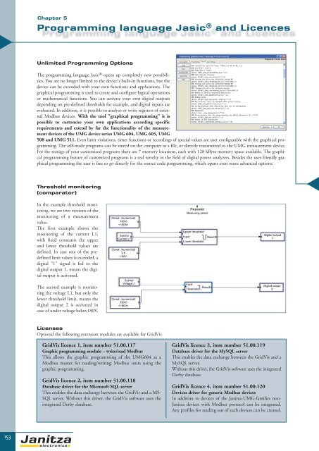
▼Chapter 5Programming language Jasic ® and LicencesUnlimited Programming OptionsThe programming language Jasic ® opens up completely new possibilities.You are no longer limited to the device's built-in functions, but thedevice can be extended with your own functions and applications. Thegraphical programming is used to create and configure logical operationsor mathematical functions. You can activate your own digital outputsdepending on pre-defined thresholds for example, and digital inputs areevaluated. In addition, it is possible to analyze or write registers of externalModbus devices. With the tool "graphical programming" it ispossible to customize your own applications according specificrequirements and extend by far the functionality of the measurementdevices of the UMG device series UMG 604, UMG 605, UMG508 and UMG 511. Even limit violations, timer functions or recordings of special values are user configurable with the graphical programming.The self-made programs can be stored on the computer as a file, or directly transmitted to the UMG measurement device.For the storage of your customized programs there are 7 memory locations, each with 128 kByte memory space available. The graphicalprogramming feature of customized programs is a real novelty in the field of digital power analyzers. Besides the user-friendly graphicalprogramming the user is free to go directly for the source code programming, which opens even more advanced options.Threshold monitoring(comparator)▼In the example threshold monitoring,we see two versions of themonitoring of a measurementvalue.The first example shows themonitoring of the current L1,with fixed constants the upperand lower threshold values aredefined. In case one of the predefinedlimit values is exceeded, adigital "1" signal is fed to thedigital output 1, means the digitaloutput is activated.The second example is monitoringthe voltage L1, but only thelower threshold limit, means thedigital output 2 is activated incase of under voltage below180V.LicensesOptional the following extension modules are available for GridVisGridVis licence 1, item number 51.00.117Graphic programming module – write/read ModbusThis allows the graphic programming of the UMG604 as aModbus master for reading/writing Modbus units using thegraphic programming.GridVis licence 2, item number 51.00.118Database driver for the Microsoft SQL serverThis enables the data exchange between the GridVis and a MS-SQL server. Without this driver, the GridVis software uses theintegrated Derby database.GridVis licence 3, item number 51.00.119Database driver for the MySQL serverThis enables the data exchange between the GridVis and aMySQL server.Without this driver, the GridVis software uses the integratedDerby database.GridVis licence 4, item number 51.00.120Devices driver for generic Modbus devicesIn addition to devices of the Janitza-UMG-families non-Janitza devices with Modbus protocol can be integrated.Any profiles for reading out of such devices can be created.153