Power Quality Monitoring
Power Quality Monitoring
Power Quality Monitoring
- No tags were found...

Create successful ePaper yourself
Turn your PDF publications into a flip-book with our unique Google optimized e-Paper software.
“<strong>Quality</strong> is never an accident;it is always the result of intelligent effort.”John Russkin▼UMG 604 power analyserReduce electricity costsStabilise production processesReliable supply with energyReduce maintenance costs
Chapter 01Company profile 33P-strategy 5An overview of application options 6Chapter 02Energy Measurement Technology<strong>Power</strong> <strong>Quality</strong> <strong>Monitoring</strong> 7An overview of UMG families 9UMG 103 – universal measuring instrument for DIN rails 12UMG 104 – power analyser for DIN rails 18UMG 604 – power analyser for DIN rails 24UMG 605 – power quality analyser for DIN rails 32UMG 96L/UMG96 – universal measuring instrument 96x96mm 38UMG 96S – universal measuring instrument with M-Bus, Modbusand Profibus/harmonics display 44UMG 503 – 144 x 144mm power analyser 52UMG 505 – power analyser with LON and analogue IOs 60UMG 507 – power analyser with continuous measurements,Ethernet and short term interruption detection 68UMG 508 – multifunctional power analyser 76UMG 511 – class A power quality analyser in accordance withIEC61000-4-30 and PQ reports for EN50160/61000-2-4 82Chapter 03<strong>Power</strong> Management 89Electronic impulse-energy meter 92Peak demand management, UMG 507Emax 100Data logger, ProData ® 106Chapter 04<strong>Power</strong> <strong>Quality</strong> Solutions 111<strong>Power</strong> factor controller, Prophi ® 114<strong>Power</strong> capacitors for power factor correction 120Conventional PFC without reactors (PFC), 124Detuned power factor correction (PFC),harmonic filters 130Dynamic power factor correction (DPFC) 138Chapter 05Software 145GridVis, OPC Server, MS Excel analysis tools 148Chapter 06Accessories 161Current transformer, mechanical accessories, field buscomponents, data server, touch panels, ... 164Chapter 07Appendix 205PFC cable diameters, fuses, cos-phi selection table,project descriptions 206
3▼Chapter 1Janitza electronics ®The storyJanitza ® electronics GmbH was founded by Mr. Eugen Janitza andMr. Markus Janitza in Lahnau in the year 1986. After EugenJanitza, one of the co-founders, retired from the company, hisson, Markus Janitza, took over as general manager.As a medium-sized family company, Janitza electronics ® GmbHis an important employer in the region with a significantupwards tendency. The management is dedicated to the site inGermany which is testified by the continual, active apprentice -ship schemes for young talents. The complete chain of valuecreation including product development, production and sales isbased in Lahnau and the major expansion of production area atthe beginning of 2007 shows that this will continue to be thecase in the future. Traditional values such as continuity and reliabilityare of great interest to our customers along with innovativetechnology and products together with a rapid, professionalservice.▼
The customersJanitza electronics ® GmbH products are generally of interest to allprofessional consumers of electrical energy. The products fromJanitza electronics ® are already used by 17 companies which arelisted in the German Shares Index (DAX). The most importantcustomers are in the automobile industry, the banking and insurancesector or local councils. The products are used in industry,commercial buildings, by energy suppliers, in airports, supermarkets,universities and in hospitals. However, the use of our productsis also lucrative for smaller companies.Janitza electronics ® GmbH has an export ratio of approximately50% and markets its products in more than 60 countries throughoutthe world.The focusJanitza electronics ® GmbH is a leading global manufacturer inthe field of digital integrated measuring equipment for energydistributors, energy optimisation systems and power qualitysolutions. The products made by Janitza electronics ® are generallyused to reduce energy, maintenance and products costs.Awareness of power quality has gained significance in allcompanies in the past years. Excessive power quality distortionlead to increased wear and tear in all electrical supply equipmentand any connected electrical and electronic loads andcan lead even up to production stoppages. Our measuringinstruments therefore provide essential information aboutinsufficient power quality and hence enable customers to takemeasures for the improvement of power quality problems.This leads to a longer lifespan for equipment and improvedsustainability of the respective investments.The possibility of allocating energy costs to certain products isbecoming more and more important to industrial companies.Janitza electronics ® also has customised solutions for cost centreanalysis.The reduction of expensive peak demand loads and the compensationof reactive power can immediately cut down theelectricity bill.Reflow soldering machine in the PQM device production4
5▼Chapter 1Janitza’s ®3P-StrategyJanitza’s ® 3P-Strategy<strong>Power</strong> <strong>Quality</strong> <strong>Monitoring</strong> - <strong>Power</strong> Management - <strong>Power</strong> <strong>Quality</strong> SolutionsThe products, systems and services of Janitza electronics ® range from measurement (collection of data) through energymanagement to solutions for the improvement of power quality. Janitza electronics ® does not solely limit itself to the collectionof data but, based on the measurement data, offers customised solutions in the fields of power quality and power management.This one-stop offer supports the best possible efficiency and power reliability.<strong>Power</strong> Management Peak demand management Collection of data Cost centre management Energy efficiency<strong>Power</strong> <strong>Quality</strong> <strong>Monitoring</strong> Measurement <strong>Monitoring</strong> Automatic alarm management Detection of PQ problems<strong>Power</strong> <strong>Quality</strong> Solutions <strong>Power</strong> factor correction (PFC) Harmonic filters Dynamic PFC▼
An overview of application optionsSwitch:Communication usingTCP/IP, internetJanitza ® UMG 511:EN50160 Standard<strong>Monitoring</strong> of power qualityClass A <strong>Power</strong> <strong>Quality</strong> <strong>Monitoring</strong>Computer environment:- Programming and assessment software- Cost centre data collection- <strong>Power</strong> quality- Analysis tools- Database management- Etc.Janitza ® UMG 508:<strong>Monitoring</strong> the reliability of voltage supplies<strong>Monitoring</strong> short-term interruptionJanitza ® Prophi ® :Reactive power controllerJanitza ® UMG 604, UMG 503 - 507:Cost centre analysis, consumer data collection, ...Janitza ® ProData ® :Data loggerJanitza ® UMG 507 EMax:Peak demand managementJanitza ® UMG 103 / UMG 96S:<strong>Monitoring</strong> important energy and electrical data; replacement for analogue measuring equipmentFixed & automaticpower factorcorrectionDynamicpower factorcorrectionDe-tunedcapacitor banksharmonic filtersJanitza ® <strong>Power</strong> <strong>Quality</strong> Solutions6
▼Chapter 2<strong>Power</strong> <strong>Quality</strong> <strong>Monitoring</strong>UMG 103 Pages 12 - 17- Universal measuring device for DIN rail mounting without display- Interface and harmonic measurement up to 25th in current and voltageNewUMG 104 Pages 18 - 23- <strong>Power</strong> analyser for DIN rail mounting with display- Interface and harmonic measurement up to 40th in current and voltageUMG 604 Pages 24 - 31- <strong>Power</strong> analyser for DIN rail mounting- 800 various measurement parameters- Continuous measurement with recognition of short-term interruptions- Ethernet, Bacnet, Modbus, Profibus, RS232, RS485- Extendable up to 7 user programs (graphic programming)- Peak demand management; accuracy classification 0.5SNewUMG 605 Pages 32 - 37- <strong>Power</strong> quality analyser for DIN rail mounting according toEN50160 and EN61000-2-4- 2000 various measurement parameters- THD, flicker, short-term interruptions, transients, unbalanced ...UMG 96L/UMG 96 Pages 38 - 43- Digital diversity in comparison to analogue simplicity- Universal measuring device (96x96mm)- UMG 96 with pulse outputs/signal outputUMG 96S Pages 44 - 51- Economic universal measuring device with interface- 2 digital outputs (as pulse or signal output)- Profibus/Modbus/M-bus/ harmonic display- Clock/memoryUMG 503 Pages 52 - 59- <strong>Power</strong> analyser (144x144mm)- Extended measurement range, higher accuracy- Modbus, RS232, RS485, 2 relay outputs,pulse output, analogue outputUMG 505 Pages 60 - 67- <strong>Power</strong> analyser (144x144mm)- LON, Modbus, RS232, RS485- 5 digital outputs, 4 analogue outputs, 4 digital inputsUMG 507 Pages 68 - 75- <strong>Power</strong> analyser (144x144mm)- Continuous measurement with detection of short-term interruptions- Ethernet, Modbus, Profibus, RS232, RS485- 6 digital inputs and outputs, 2 analogue outputs, 1 temperature input- Peak demand managementNewUMG 508 Pages 76 - 81- <strong>Power</strong> analyser (144x144 mm)- Continuous measurement with recognition of short-term interruptions- Ethernet, Modbus, Profibus, RS485- THD, short-term interruptions, transient, unsymmetrical ...NewUMG 511 Pages 82 - 88- Class A power quality analyser according to IEC61000-4-30<strong>Power</strong> quality reports in line with EN50160 and EN61000-2-4- Harmonics up to a 63 rd- THD, flicker, short-term interruptions, transient, unsymmetrical ...- Including GridVis software with report generator for EN50160▼7
PQM - <strong>Power</strong> <strong>Quality</strong> <strong>Monitoring</strong>PQM - <strong>Power</strong> <strong>Quality</strong> <strong>Monitoring</strong>Energy measurement technologyThe first step towards saving energy and improving operational processes is the measurement of themost important parameters of your electrical energy supply while monitoring the peak loads.Janitza electronics ® offers you a complete range of powermonitoring units with the corresponding accessories.The UMG measuring equipment and power analysershelp you to gain a comprehensive overview of yourenergy supplies and introduce the correct measures.The power quality is also monitored according to thegeneral valid standards (e.g. EN50160). TheGridVis software packages in connection withthe measurement equipment and poweranalysers from Janitza electronics ® offeryou energy and power monitoringwith real-time diagnosis from theprovider through to all levels of yourenterprise.8
▼Chapter 2Overview of universal measuring instrumentsTypeItem numberUMG 10352.18.00152.20.001UMG 104P52.20.002UMG 604L E P EP52.16.00352.16.00252.16.00452.16.001UMG 60552.16.027UMG 96L52.14.001(52.14.005)Measurement range L-N, ACMeasurement range L-L, ACOver voltage categoryOperating voltage L-N, ACAuxiliary voltageThree phase/four phaseQuadrantsScan frequency 50/60HzMeasurement points per sec.Continuous measurementMeasurements per secondEffective value from periods50/60HzHarmonics V/ADistortion factor THD-U in %Distortion factor THD-I in %UnbalancePositive/negative/zero systemCurrent flicker strengthShort/long-term flickerTransientsShort-term interruptionsAccuracy V, AEffective energy classificationOperating hour meterWeekly time switchAuxiliary inputDigital inputsDigital/pulse outputRelay outputsAnalogue inputsAnalogue outputsTemperature inputIntegrated logicMin/max value memoryMemory size50 - 300V85 - 520V300V CAT III115-240V--/•45,4kHz5,400•510/121.3 ... 25••••----+-0.2%0.5S•---------•-10 - 600Vrms18 - 1000Vrms300V CAT III-95 - 240V AC; 135 - 340V DC *1•/•420kHz20,000•510/121 - 40••••----+-0.2%0.5S•--22---1-•4MBFlash10 - 600Vrms18 - 1000Vrms300V CAT III-95 - 240V AC; 135 - 340V DC *1 95 - 240V AC; 135 - 340V DC *1•/•420kHz20,000•510/121 - 40••••--50µs•+-0.2%0.5S•• Jasic ®-22---1Jasic ® (7 Prg.)•128 MB Flash10 - 600Vrms18 - 1000Vrms300V CAT III-•/•420kHz20,000•510/121 - 63••••••50µs•+-0.2%0.5S•• Jasic ®-22---1Jasic ® (7 Prg.)•128 MB Flash50 - 255V, (16 - 80V) *186 - 442V, (28 - 139V) *1300V CAT III196 - 255V, (45 - 80V) *1--/•4 *42.5/3kHz50-11/1---------+-1%2•---------•-▼Number of storage values-156k5,000k5,000k-9ClockBi-metallic function A/kWFault recording functionPeak demand managementSoftwareInterfacesRS 232RS 485Profibus DPM-BusLONEthernetWeb server / e-mailProtocolsModbus RTUISDN routerModbus gatewayProfibus DP V0LonTalkModbus TCP/IP,Modbus over TCPBACnet IP/MSTPCatalogue page-•--GridVis-•-----•------12•••-GridVis• •• •- •- -- -- -- -• •- -- -- •- -- -- -18••••GridVis• • • •• • • •- - • •- - - -- - - -- • - •- •/• - •/•• • • •- • - •- • - •- - • •- - - -- • - •-/• •/• -/• •/• *324••••GridVis*1 Other voltages are available as options(2) Combination options for inputs and outputs: a) 2 digital outputs, b) 2 digital inputsc) 2 analogue outputs, d) 1 digital output and 1 analogue output, e) 1 digital output and 1 digital input•••--••/•••••-••/• *332-•-----------------38
TypeUMG 96UMG 96SUMG 508UMG 511Item number52.09.001(52.09.002)52.13.00152.13.00552.13.00952.13.01752.13.01352.13.02152.13.02552.13.04052.13.02952.21.00152.19.001Measurement range L-N, ACMeasurement range L-L, ACOver voltage categoryOperating voltage L-N, ACAuxiliary voltageThree phase/four phaseQuadrantsScan frequency 50/60HzMeasurement points per sec.Continuous measurementMeasurements per secondEffective value from periods50/60HzHarmonics V/ADistortion factor THD-U in %Distortion factor THD-I in %UnbalancePositive/negative/zero systemCurrent flicker strengthShort/long-term flickerTransientsShort-term interruptionsAccuracy V, AEffective energy classificationOperating hour meterWeekly time switchAuxiliary inputDigital inputsDigital/pulse outputRelay outputsAnalogue inputsAnalogue outputsTemperature inputIntegrated logicMin/max value memoryMemory sizeNumber of storage valuesClockBi-metallic function A/kWFault recording functionPeak demand managementSoftwareInterfacesRS 232RS 485Profibus DPM-BusLONEthernetWeb server / e-mailProtocolsModbus RTUISDN routerModbus gatewayProfibus DP V0LonTalkModbus TCP/IP,Modbus over TCPBACnet IP/MSTPCatalogue page50 - 275V, (49 - 76V) *186 - 476V, (85 - 132V) *1300V CAT III196 - 275V, (49 - 76V) *1--/•4 *42.5/3kHz50-11/1---------+-1%2•---•----Comparator•---•-----------------3850 - 300V ( 25 - 150V) *187 - 520V300V CAT III85-300V(5213025/35; 140 -300V) -nur 52.13.029; 18 - 70V DC, 18 - 33V AC-/•41.5kHz180-16/61.3 ... 15••------+-0.5%1•--- - - - - (2) (2) (2) (2)2 2 2 2 2 (2) (2) (2) (2)--- - - (2) (2) - - - --Comparator•- -- -512k512k160k160k- - - - -- - - - -- - • • - - - - -•--GridVis- •• -- • - •- - • ----•--- - - - - - • - •---4410 - 600V18 - 1000V600V CAT III-95 - 240V AC; 135 - 340V DC•/•420kHz20,000•510/121 - 40••••--50µs•+-0.1%0.2S••-85----• Jasic ®•256MB10,000k••••GridVis-••--••/•••••-••/• *37610 - 600V18 - 1000V600V CAT III-95 - 240V AC; 135 - 340V DC•/•420kHz20,000•510/121 - 63••••••50µs•+-0.1%0.2S••-85----• Jasic ®•256MB10,000k••••GridVis-••--••/•••••-••/• *382*3 Option *4 Not for effective and reactive power: Included- : Not included10
11▼Chapter 2Overview of universal measuring instrumentsTypeItem numberUMG 503L LG LS S OV V52.07.01752.07.02752.07.02852.07.00852.07.00652.07.001UMG 505MOD MOD LON LON52.10.00452.10.00752.10.00152.10.013UMG 507L EL AD P E EP52.15.00452.15.02152.15.00352.15.00252.15.00152.15.005Measurement range L-N, ACMeasurement range L-L, ACOver voltage categoryOperating voltage L-N, ACAuxiliary voltageThree phase/four phaseQuadrantsScan frequency 50/60HzMeasurement points per sec.Continuous measurementMeasurements per secondEffective value from periods50/60HzHarmonics V/ADistortion factor THD-U in %Distortion factor THD-I in %UnbalancePositive/negative/zero systemCurrent flicker strengthShort/long-term flickerTransientsShort-term interruptionsAccuracy V, AEffective energy classificationOperating hour meterWeekly time switchAuxiliary inputDigital inputsDigital/pulse outputRelay outputsAnalogue inputsAnalogue outputsTemperature inputIntegrated logicMin/max value memoryMemory size50 - 500V80 - 870V600V CAT III-85 - 265V AC; 80 - 370V DC *1•/•46.4/7.68kHz256-22/21 - 20••------+-0.2%1--- - - - 1 *3 1- - - - - -- - - - 1 *3 •- - - - 2 *3 2- - - - - -- - - - 1 *3 1-Comparator•128k512k128k128k512k512k50 - 500V80 - 870V600V CAT III-85 - 265V AC; 80 - 370V DC *1•/•46.4/7.68kHz256-22/21 - 20••------+-0.2%1-•-45--4-Comparator•512k50 - 500V80 - 870V600V CAT III-85 - 265V AC; 80 - 370V DC *1•/•41.65/1.98kHz1,650/1,980•510/101.3 - 15••••---•+-0.2%1••-6 - 6 6 6 66 - 6 6 6 6- - - - - -- - 1 1 1 1- - 2 2 2 2- - 1 1 1 1••256k16MB256k256k16MB16MB▼Number of storage values80k320k80k80k320k320k320,00018k1.000k18k18k1,000k1,000kClockBi-metallic function A/kWFault recording functionPeak demand managementSoftwareInterfacesRS 232RS 485Profibus DPM-BusLONEthernetWeb server / e-mailProtocolsModbus RTUISDN routerModbus gatewayProfibus DP V0LonTalkModbus TCP/IP,Modbus over TCPBACnet IP/MSTPCatalogue page••--GridVis• • - - • •- - • • • •- - - - - -----• • • • • •- - - - - -- - - - - -- - - - - -- - - - - -- - - - - -- - - - - -52••--GridVis• - • -- • - •- - - -- - - -- - • •- - - --/- -/- -/- -/-• • • •- - - -- - - -- - - -- - • •- - - -- - - -60••••GridVis• • • • • •• - • • • •- - - • - •- - - - - -- - - - - -- • - - • •- •/• -/- -/- •/• •/•• • • • • •- • - - • •- - - - • •- - - • - •- - - - - -- • - - • •- - - - - -68*1 Other voltages are availableas options(2) Combination options for inputsand outputs:a) 2 digital outputs,b) 2 digital inputsc) 2 analogue outputs,d) 1 digital output and1 analogue output,e) 1 digital output and1 digital input*4 not for effective and reactivepower: Included- : Not included
PQM - <strong>Power</strong> <strong>Quality</strong> <strong>Monitoring</strong>Universal measuring equipmentfor DIN rail mountingUniversal measuring devices of the UMG 103 product family are mainly designed for use in low voltagedistribution systems.UMG 103The UMG 103 is a measuring instrument with an effective energy class of 0.5S. <strong>Monitoring</strong> harmonicsIn addition to a large quantity of electrical measurement values, the UMG 103 offers a multitude ofadditional functions such as the measurement of harmonics, the storage of minimum and maximumvalues, operating hour meter, bi-metallic strip function and password protection. The interface andfield bus capabilities (Modbus) enable the communication of measurement data and incorporationinto a comprehensive energy management system.Areas of application For measuring and checking electrical parameters in energy distribution systems Cost centre management solutions for data collection Limit value monitoring, measurement value generator for building management systems or PLC12
▼Chapter 2Universal measuring instrumentUMG 103 universal measuring devicefor DIN rail mountingThe UMG 103 is a very compact universal measuring instrument formounting on DIN rails. The compact dimensions even enable installationin limited spaces such as in installation sub-distribution boards.Installation and connection costs are significantly reduced by mountingthe instrument on a 35mm DIN rail.In order to make use of the extensive functions of modern measuringinstruments, the interconnection and central analysis of data plays animportant role. This is the reason for not using a display; two LEDs showthe current operating status. The communication of measurement datatakes place through a very fast RS485/Modbus interface.The UMG 103 performance level is usually sufficient for sub-measurementsin connection with higher performance power analysers such as the UMG 604 or the UMG 508 applied in more complexenergy management systems. In this case, the UMG 103 serves as data measurement point which takes the measurement data andpasses it on to a higher-level point (master device). Using power analysers such as the UMG 604 with an integrated Modbus/Ethernetgatewayand integrated web server, data are brought onto the Ethernet level or are visualised on the homepage. Some examples ofapplications are cost centre management systems in office buildings, monitoring feeders to sub-distribution panels, motor control centresor in IT and data centres.▼Main features Measurement in TN and TT networks 3 voltage measurement inputs (300V CATIII), 3 current measurement inputs Continuous scanning of the voltage and current measurement inputs High measurement accuracy, effective energy class 0.5; U/I, 0.2% Harmonic analysis up to the 25th order Including GridVis software RS 485 (Modbus RTU, slave) Mounting on 35mm DIN rail Suitable for integration in installation distribution panelsApplicationsThe UMG 103 is intended for the measurement and calculation ofelectrical parameters such as current, voltage, power, consumptionor harmonics etc. in building installations, on distribution panels,on circuit breakers and on server racks. The UMG 103 is fixed intocabinets or small installation distributors in any installation position.The measurement values can be read out using the serial interface.The highest, lowest and energy values are recorded every twoseconds in a non-volatile memory. The voltage measurementinputs are designed for the measurement in low voltage networksin which nominal voltages up to 300V against ground andsurge voltages up to over voltage category III can occur. TheUMG 103 is mainly suitable for measurements in low voltagenetworks because it takes the supply voltage from the measurementvoltage and a voltage converter would be thereforenecessary for HV grids.13
UMG 103Communication optionsThe connection of a UMG 103 to a PC using an interface converterInterface converterRS232 / RS485 orUSB / RS485UMG 103The connection of several UMG 103’s to a PC using a UMG 604 (with optional Ethernet)SwitchUMG 604EModbus using RS485UMG 103 UMG 103 UMG 10314
▼Chapter 2Functions and technical dataOverview of product variantsDescription Type Operating voltage Item numberUniversal measuring device 50/60Hz;Current transformer: ../1/5AUMG 103 L-N: 115 ... 240 VAC 52.18.001Measurement rangeVoltage L-NVoltage L-LCurrent (CTs: x/1 and x/5A)Frequency, mains50-300 V-AC85-520 V-AC0.001...7.5A45...65 HzGeneral technical dataOperating voltage CAT III 110 ...240 V-ACScanning rate5.4 kHz per channelQuadrants 4Weight150gDimensionsB=71.5 mm, H=90 mm, T=46 mmMounting35 mm DIN railWorking temperature -10…+55 °CStorage temperature -20…+70 °CProtection class According to EN 60529 IP20Connectable conductors (U/I)Single wire, multi-wire, fine-wirePin cable lugs, ferrule0.08-2.5 mm 21.5 mm 2Measurement valuesVoltage L1, L2, L3, L1-L2, L2-L3, L1-L3 0.2% rdg + 0.02% rngCurrent L1, L2, L3, N calculated 0.2% rdg + 0.02% rngEffective, reactive and apparent power L1, L2, L3, sum Accuracy ±(0.4% rdg + 0.10% rng)Cos-phi, power factorL1, L2, L3, sumEffective/reactive energy Consumed/inductive Class 0.5S(kWh)Frequency L1, L2, L3 Accuracy ±0.1% rdgAverage valueYesMinimum/maximum valueYesOperating hour meterYes<strong>Power</strong> qualityHarmonics 1-25th harmonic order,uneven Current, voltage, L1, L2, L3 Accuracy: 0.5% rdg + 0.05% rngDistortion factor THD-U in % L1, L2, L3 Accuracy: 0.5% rdg + 0.05% rngDistortion factor THD-I in % L1, L2, L3 Accuracy: 0.5% rdg + 0.05% rngCommunicationInterfacesRS 485 Up to 115.2 kbps YesProtocolsModbus RTU/slaveYes15
▼UMG 103Typical connection optionsUMG 103Illustration: connection option UMG 103Illustration: connection example for a voltagemeasurement using a voltage transformer (VT)Illustration: current measurement using a sum currenttransformer (CT)16
▼▼Chapter 2UMG 103Mounting illustrationSupport railDimensional drawingsIllustration: front viewIllustration: side view17
UMG 104PQM - <strong>Power</strong> <strong>Quality</strong> <strong>Monitoring</strong>More than just aMultimeterThe UMG 104 equipped with a 500 MHz DSP (digital signal processor) is a very fast and powerfulpower analyser.The continuous scanning of the 8 channels with 20 kHz per channel allows the recording of all electricalparameters (more than 800 values), minimum - and maximum - values, and the main powerquality values such as harmonics (up to the 40 th , each phase with the detection of direction).Based on these data loss of production can be avoided, concepts can be developed, such as the electricitycost reduction programs, and measures introduced. And finally the improvements can bemonitored and recorded with the UMG 104 as well.Using modern communication architectures, the acquired data are fed to a central location, in powerfuldatabases, stored centrally and made available for further processing in an open architecture. Theeasy integration into an existing building control system or PLC environment extends the capabilitiesof the UMG 104.Applications: Replacement of analogue and digital instrumentation Consumption data collection and analysis (load profiles) Continuous power quality monitoring Cost center management, i.e. breakdown of energy costs, e.g. allocation per product Remote control and monitoring of equipment and processes Protection of networks “Sensor” for building management systems or PLC18
▼▼Chapter 2<strong>Power</strong> analyserexcess value by additional functionsBy integration of new functions, the UMG 104exceeds all limits of digital panel meters:Multifunctional power meterkWh-meter, kvarh-meterHarmonic AnalyzerSupervision of conditionEvent writerData loggerThe UMG 104 can accept up to 4 current and 4 voltage inputs, which allows monitoring of upto 4 single phase circuits. Potential applications include data centers, office buildings, motorcontrol centers, etc.Cost-effective, fast and safe communicationModbus and ProfibusIn many cases the costs for installation and communication (e.g. peripheralequipment for field buses) exceed those for the respective power meters.Integration of the UMG 104 in an existing field bus architecture means a fast,cost-efficient and reliable communication. Additional interfaces enable the integrationof the power analysers into PLC or building automation systems. The useof open standards offers great flexibility to the user.RS 485UMG 104Easy integration of devices with EthernetinterfaceWith the Modbus interface function of UMG 104 you can connect via Modbusgateways (for example UMG 508, UMG 604, ...) to Ethernet. Each instrumentwith a Modbus RTU interface can be connected, if its data format and functioncodes correspond. Data can be scaled and labelled.Example PLC communication with Profibusor ModbusUMG 508 UMG 104RS 485Highspeed ModbusThe devices of UMG 104 series can transfer data via RS485 interface with aspeed of up to 921.6 kB/s among each other device of this series.ExampleEthernet gateway19
▼Chapter 2Functions and technical dataOverview of product variantsThree/four phase power analysers; 50/ 60Hz; current transformer ../1/5A; including GridVis programming and analysis software.Supply VoltageInterfaces95...240 V AC,135...340 V DC50...110V AC50...155V DC20...55V AC20...77V DC4 Voltage and4 Current inputs2 Digital inputs2 Digital outputs1 Temperature inputRS 232RS 485Profibus DP V0TypeItem no. - UMG 104 52.20.001 - UMG 104 52.20.003 - UMG 104 52.20.005 UMG 104 P 52.20.002 UMG 104 P 52.20.004 UMG 104 P 52.20.006- = not possible = includedFeaturesMemory Measurement data 4 MBClock+/- 1 min per monthOperating hours counteryesTarifs4 x real energy / 4 x reactive energyPeripheralsDigital inputs as status or pulse input 2Digital outputs as switching or pulse output 2Temperature input PT100, PT1000, KTY83, KTY84 1Password protectionyesSoftware GridVis yesCommunicationInterfacesRS 232 9.6, 19.2, 38.4, 115.2 kbps yesRS 485 9.6, 19.2, 38.4, 76.8, 115.2, 921.6 kbps yesProfibus DP Sub D9-pole up to 12 Mbps yes, variant PProtocolsModbus RTUyesProfibus DP V0yes, variant P21
▼UMG 104Technical dataSupply voltage L- N, AC see page 9Overvoltage class300 V CATIIIQuadrants 4Continuous MeasurementyesSampling rate, 8 channels per channel 20 kHzWeight350 gDimensionsW=107.5 mm x D=90 mm x H=82 mmMounting according to IEC EN60999-1/ DIN EN 50022 35 mm DIN railWorking temperature -10…55 °CConnectable wires (U/I) one wire, more wires, fine stranded wires 0.08 - 2.5 mm²cable end sleeve1.5 mm²Protection class according to EN60529 IP 20Measuring rangeVoltage L-N, AC (without PT)Voltage L-L, AC (without PT)Current (Transformer: x/1 und x/5 A)Frequency of fundamentalGridsMeasurement in grids10…300 V AC17…520 V AC0.005...7.5 A45 ..65 HzIT, TN, TT1ph, 2ph, 3 ph, 4 phup to 4 times 1phMeasured valuesVoltage L1, L2, L3, L4, L1-L2, L2-L3, L1-L3 accuracy ±0.2%Current L1, L2, L3, L4, Sum L1-L3, Sum L1-L4 accuracy ±0.2%K-factor L1, L2, L3, L4 yesRotating current components Positive/ Negative/ Zero Phase Sequence yesReal, apparent, reactive power L1, L2, L3, L4, Sum L1-L3, Sum L1-L4 accuracy ±0.4% (EN61557-12)Cos-phi / power factor L1, L2, L3, L4, Sum L1-L3, Sum L1-L4 yesPhase angle L1, L2, L3, L4 yesReal energy (kWh)Reactive energy (Karh)L1, L2, L3, L4, Sum L1-L3, Sum L1-L4:- Consumed real energy (rate 1, rate 2)- Supplied real energy (rate 1, rate 2)L1, L2, L3, L4, Sum L1-L3, Sum L1-L4:- Inductive energy (rate 1, rate 2)- Capacitive reactive energyClass 0.5S (…/5 A),Class 1 (…/1 A)Class 2Reactive energy (kVAh) L1, L2, L3, L4, Sum L1-L3, Sum L1-L4 yesWave form voltage L1, L2, L3, L4 yesFrequency of mainsaccuracy ±0.01 HzTemperature inputaccuracy ±1.5% rngAverage valuesyesMinimum and maximum valuesyes<strong>Power</strong> qualityHarmonics, 1st- 40thCurrent, voltage, real/reactive power (±)L1, L2, L3, L4Distortion factor THD-U in % L1, L2, L3, L4 yesDistortion factor THD-I in % L1, L2, L3, L4 yesUnbalancePositive/ Negative/ Zero Phase SequenceInrush-currents 10 ms noMalfunction writerShort-term interruptionsaccuracy V, I Class 1 (EN61000-4-7)yesyesnono22
▼▼Chapter 2UMG 104Connection diagram UMG 104Dimensional drawingfront viewside view90 mm90 mm107,5 mm50 mm76 mm82 mm23
UMG 604PQM - <strong>Power</strong> <strong>Quality</strong> <strong>Monitoring</strong>High performance power analysersfor DIN railsHigh performance power analysers from the UMG 604 product family are suitable for use at all networklevels. The high scanning rate enables a continuous measurement by gathering more than 800measurement parameters. Due to the very high performance level of the digital signal processor, allimportant power quality parameters are recorded e.g. short-term interruptions with fault recorderfunction, transients, harmonics up to a 40 th and starting current etc. Extensive communication optionse.g. Ethernet (TCP/IP), BACnet, Modbus, Profibus, RS232, RS485, HTTP, FTP, SMTP, SNTP,SNMP or DNS… allow affordable and quick integration in the existing communication architecture.Worldwide access to the embedded web server can be gained through a web browser e.g. for energyconsumption analysis. Programs specific to the user can be created with implemented graphic programming.It is possible to run 7 user programs simultaneously.Areas of application For measuring, monitoring and checking electrical parameters in energy distribution units Consumption data collection and analysis (cost centre data collection) For monitoring the power quality (harmonics, short term interruptions, transients,initial current…) Measurement value generator for building management systems or PLC Control tasks e.g. depending upon the achieved measurement values or limit values Peak demand management (avoidance of costly and dangerous peak loads) Ethernet gateway for subordinate measurement points Remote monitoring24
▼Chapter 2<strong>Power</strong> analyserUMG 604: the extra compactpower analyserAdded value through additional functionsThrough the integration of various functions, the UMG 604power analyser goes far beyond the limits of digital multifunctionalmeasuring equipment and, therefore, offers the respective addedvalue. The UMG 604 and the use of state-of-the-art processorsallow to offer a very fast and extremely compact power analyser atan affordable price. The UMG 604 contains the following functions:<strong>Power</strong> analyser for electrical energy distribution(over 800 parameters)Energy consumption and cost centre data collection<strong>Monitoring</strong> of power qualityPeak demand management (optional)PLC function (up to 7 simultaneous freely programmableprograms, graphic programming)Transient recorderEvent recorderData loggerModbus/Ethernet gateway▼Main featuresContinuous measurement Collection of all relevant power quality parameters (harmonics, short-term interruptions, unbalance ...) Ethernet and embedded web server Jasic ® interpreter Up to 7 user defined programs GridVis software - full version included in the deliveryApplicationsMajor increases of energy costs make electrical energy a driving forcein costing. With the UMG 604, you can make the first step towardsbetter cost efficiency. The precise collection of all energy data andelectrical parameters ensures the necessary amount of transparency inyour energy supplies. Concepts can be developed on the basis of thedata e.g. electricity cost reductions and the introduction of measures.These targeted improvements can also be monitored and recordedwith the UMG 604.The UMG 604, equipped with a 500 MHz DSP (digital signalprocessor), is a fast and high performing power analyser. Thecontinuous scanning of eight channels with 20 KHz per channelenables the collection of all relevant electrical parameters (morethan 800 values), minimum and maximum values, the basicpower quality values such as harmonics (up to the 40 th , eachphase with direction recognition) and short-term interruptions.Even fast transients (> 50µs) can be safely identified. Usingmodern communication processes, the collected data is conductedto a central location, stored centrally in a high-performancedatabase and provided for further processing in an opensystem. Simple integration in an existing building managementsystem control or PLC environment expands the areas of applicationof the UMG 604.25
UMG 604DIN rail mounting (6 units): reduction ofinstallation costsMeasurement equipment is usually installed in the low voltagemain distribution as an integral measurement instrument for theswitchgear cabinet door. Installation and connection costs aresignificantly reduced by the installation of the UMG 604 on a35mm DIN rail. This means that the panel cut-out and wiring tothe cabinet door is no longer necessary. In order to make use of theextensive functions of modern measuring equipment, the interconnectionand central analysis of the data plays an importantrole. This means that the on-site display generally serves the purposeof the initialisation and service only.The decidedly compact UMG 604 is suitable for installation inlow voltage main distribution panels and machines as well as ininstallation distribution boards which is particularly of interest forapplications in building services engineering, information technologyand data centres.Modern communication processesthrough the Ethernet: affordable, rapidand safe communicationThe costs for installation and communication (e.g. periphery for fieldbuses) often surpass the costs of the equipment.By connecting the equipment to an existing Ethernet system, a fast,optimally priced and reliable communication system can be developed.Additional interfaces allow the integration of power analysers inPLC systems or in central building management systems. The use ofclear standards offers the user a high amount of flexibility.Modbus gateway: the affordableconnection of units without anEthernet interfaceWith the Modbus gateway function, simple Modbus RTU-units canbe connected to the Ethernet using the UMG 604. For example, theUMG 604 can be used simultaneously as a gateway for subordinatemeasurement points or older units which already exist in the installation.Each unit with a Modbus RTU interface, where the data formatand function codes match up, can be connected. Data can be markedand scaled.High-speed ModbusThe devices of the UMG 604 series can transfer data between the units using the RS485 interface at a speed of up to 921.5 kB/s.The e-mail and homepage inform youwherever you are…Who hasn’t experienced it before? You are hardly through the doorand the telephone is already ringing. There are problems in production,computers are crashing and the energy supplies are lost.You have direct access to the extremely high performance homepageof the UMG 604 with a web browser and an IP address. Extensiveinformation is already available to you on the homepage. Online dataare available together with historical data and graphs recording events.The homepage can be used to directly convert the rates into costs andbe exported as a csv file or printed. As an alternative, you can let yourselfbe informed by e-mail anywhere in the world if your energy supplybecomes overloaded, if short-term interruptions to the voltagesupplies bring your production processes to a standstill or unauthori -zed harmonics reduce the lifespan of equipment. The application possibilitiesare endless.26
▼Chapter 2<strong>Power</strong> analyser<strong>Power</strong> visualisation softwareThe data gained from various measurement points must be collected, saved, visualised and made available. The GridVis software containedin the UMG 604 package allows Parameterisation and programming of UMG measurement equipment Visualisation of the measurement values with topological view Automatic download of the measurement data Data storage Online analysis tools Analysis tools for historic dataVisualisation, topological viewGridVis allows an individually adaptable visualisation of online data. The topological view provides a rapid overview of energy distributionwith the possibility of localising power faults by comparing the individual measurement points and by offering the possibility to check thedefined tolerances at a glance.Customer specific solutions can be quickly and simply implemented through uploading of graphic documents (standard formats such asJPG) with circuit diagrams, production lines or construction plans and incorporating the respective measurement units by drag and dropinto their actual locations. Limit value excesses (e.g. THD-U is too high) and the status of inputs and outputs can also be displayed.Online values and analysisof historic dataWith the graphic line writer function, GridVis enablesrapid online presentation of the selected measurementvalues. In this function, the graph is continuously expandedwith new measurement values. For example, load profilescan be presented through the analysis of historic datain order to produce exact consumption analysis for optimisedelectricity supply contracts. Fault analysis throughthe comparison of various parameters can also be achievedwith a few mouse clicks.Graphic programmingThe graphic programming option for user programs is completelynew in the field of digital power analysers. Programsspecific to the application can be created with this methodsuch as the free programming of inputs and outputs, monitoringof processes or the issue of reports when defined limitvalues are achieved. In addition to the operator-friendly graphicprogramming, the user is also free to program the Jasic ®code directly.programming languageThe Jasic ® programming language offers brand newopportunities. The user is no longer tied to the functionswhich are fixed integrations in the unit; the unit can beexpanded to include more functions. Up to seven of thesefreely definable user programs can be processed simultaneouslyin the unit.27
▼Chapter 2Product variants and technical dataOverview of product variantsThree/four phase power analysers; 50/60Hz; current transformer .../1/5a; including GridVis programming and analysis softwareInterfaces95...240V AC,135...340V DCSupply voltage50...110V AC,50...155V DC20...55V AC,20...77V DC4 voltage and4 current inputsMemory128 MB Flash2 digital inputs2 digital outputs1 temperature input - UMG 604 E 52.16.002 UMG 604 EP 52.16.001 - UMG 604 E 52.16.012 UMG 604 EP 52.16.011 - UMG 604 E 52.16.022 UMG 604 EP 52.16.021Options (for all versions)Emax function application program (peak demand management) Emax 52.16.080BACnet communication BACnet 52.16.081RS 232- = not possible = contained Not suitable for use in residential areas.RS 485Ethernet 100baseTProfibus DP V07 freely programmableapplication programsTypeItem numberGeneral technical dataSupply voltage L-N, ACRefer to product variant overviewOvervoltage category300V CATIIIQuadrants 4Continuous measurementYes8 channel scanning rate Per channel 20 kHzWeight350gDimensionsL=107.5mm * W=90mm * H=62 mmMounting According to IEC EN60999-1/DIN EN50022 35mm DIN railWorking temperature range -10…55 °CConnectable conductor (U/I) Single wire, multi-wire, fine-wire 0.08 - 2.5 mm²pin cable lugs, ferrule1.5 mm²Protection class According to EN 60529 IP 20Measurement rangeL-N voltage, AC (without voltage transformer) Free voltage transformer settings 50…300 VACL-L voltage, AC (without voltage transformer) Free voltage transformer settings 87…520 VACCurrent (transformer: x/1 and x/5A)Frequency of mainsNetworksMeasurement in single/multi-phase networks0.001...7.5 A45...65 HzIT, TN, TT1 ph, 2 ph, 3 ph, 4 phand up to 4 x 1 phPeripheryDigital inputs Status, logic or pulse input 2Digital outputs Switch logic output or pulse output 2Temperature measurement input PT100, PT1000, KTY83, KTY84 1Password protection Multilevel YesPeak demand management Optional 64 channels YesSoftware GridVis Yes29
▼UMG 604Measurement valuesVoltage L1, L2, L3, L4, L1-L2, L2-L3, L1-L3 Accuracy ±(0.2% rdg + 0.02% rng)Current L1, L2, L3, L4, Sum L1-L3, Sum L1-L4 Accuracy ±(0.2% rdg + 0.05% rng)K-factor L1, L2, L3, L4 YesThree-phase current components Positive/negative/zero phase sequence YesEffective, reactive and apparent power L1, L2, L3, L4, Sum L1-L3, Sum L1-L4 Accuracy ±(0.4% rdg + 0.10% rng)Cos-phi, power factor L1, L2, L3, L4, Sum L1-L3, Sum L1-L4 YesPhase angle L1, L2, L3, L4 YesEffective energy (kWh)Reactive energy (kvarh)L1, L2, L3, L4, Sum L1-L3, Sum L1-L4:- Purchased effective energy (tariff 1, tariff 2)- Supplied effective energy (tariff 1, tariff 2)L1, L2, L3, L4, Sum L1-L3, Sum L1-L4:- Inductive reactive energy (tariff 1, tariff 2)- Capacitive reactive energyClass 0.5S (…/5A),Class 1 (…/1A)Class 2Apparent energy (kVAh) L1, L2, L3, L4, Sum L1-L3, Sum L1-L4 YesCurrent/voltage wave form L1, L2, L3, L4 YesFrequency of mainsAccuracy ±0.1% rdgTemperature measurementAccuracy ±1.5% rngAverage valueYesMinimum and maximum valuesYesFeaturesMemoryClock<strong>Power</strong> qualityHarmonics, 1-40 harmonicCurrent, voltage reactive/effective power (±)L1, L2, L3, L4Accuracy ±(0.5% rdg + 0.05 rng)Distortion factor THD-U in % L1, L2, L3, L4 YesDistortion factor THD-I in % L1, L2, L3, L4 YesUnbalanceYesPositive/negative/zero systemYesTransients 50 μs YesStart-up processes 10 ms YesFault recorder functionShort-term interruptionsCommunicationInterfacesRS 232 9.6, 19.2, 38.4, 115.2 kbps YesRS 485 9.6, 19.2, 38.4, 76.8, 115.2, 921.6 kbps YesProfibus DP Plug, sub D 9-pole up to 12Mbps Yes, EP versionEthernet 10/100 Base- TX RJ-45 sockets YesProtocolsModbus RTUProfibus DP V0Modbus TCPModbus over TCPModbus GatewayHTTP Homepage (configurable) YesSMTP E-mail YesSNMPSNTP Time synchronisation YesTFTP Automatic configuration YesFTP File transfer YesDHCPBACnet / IP or MSTP128 MB+/- 1 min per monthIntegrated logic Programming language Jasic ®Operating hour meterWeekly time switch Jasic ®YesYesYesYesYes, EP versionYesYesYesYesYesYes, option30
▼▼Chapter 2UMG 604ConnectionillustrationDimensional drawingFront viewSide view90 mm90 mm107.5 mm36 mm62 mm31
UMG 605PQM - <strong>Power</strong> <strong>Quality</strong> <strong>Monitoring</strong>High performance power quality analyserfor DIN railsaccording to EN 50160The UMG 605 power quality analyser is particularly suitable for monitoring power quality accordingto standards such as the EN 50160. All power quality parameters are collected and analysed e.g.flicker, short-term interruptions with fault recorder function, transients, harmonics up to 63 rd andinrush currents etc. Extensive communication possibilities e.g. RS 485 Modbus, Profibus, Ethernet(TCP/IP), BACnet, HTTP, FTP, SMTP, SNTP, SNMP, DNS .... allow cost effective and rapid integrationin existing communication networks. Worldwide access to the embedded web server can begained through a web browser. The GridVis software included in the content of delivery allows extensiveanalysis just with the click of a button.Areas of application Continuous monitoring of the power quality e.g. EN 50160Ethernet gateway for subordinate measurement pointsAnalysis of electrical faults for network problems <strong>Monitoring</strong> of the internal distribution network according to EN 61000-4-7, 4-15, 4-30Report generator for EN 50160 analysisControl tasks, e.g. depending on achieved measured values or limitsTransducer for building automation or PLC systems32
▼Chapter 2<strong>Power</strong> quality analyserUMG 605: the extra compact power quality analyserAdded value through additional functionsThanks to state-of-the-art digital signal processor, it is possible to offer thepower quality analyser UMG 605 at a very reasonable price. The high samplingrate enables a continuous measurement of more than 2000 measuredvalues per measurement cycle (200ms). The UMG 605 power quality analyserserves the purpose of continuous monitoring of the power quality e.g.in accordance with EN 50160. This serves the purpose of monitoring thesupply power quality from the energy supply side. The UMG 605 can alsobe used in applications for failure analysis on the consumer side and is alsoused as a preventative measure for network perturbations.Main Features Measurement of power quality according to DIN EN 61000-4-30 Measurement method class A Fourier analysis 1 st to 63 rd harmonics for U-LN, U-LL, I, P (consumption/supply) and Q (ind./cap.) Measurement of harmonics and interharmonics (U-LN, U-LL, I) Analysis and evaluation according to DIN EN 50160 with the contained programming and analysis software GridVis Flicker measurement according to DIN EN 61000-4-15Measurement in IT and TT grids (300V CATIII)4 voltage measuring inputs, 4 current measuring inputsContinuous sampling of the voltage and current measuring inputs with 20kHzRecording of more than 2000 different measurement parameters per measuring cycle (200ms)Detection of transients >50µs and storage with up to 16.000 samplesData logger / event memory (128MB Flashdisk)2 digital inputs and 2 digital outputsProfibus DP/V0 alternatively RS 485 (Modbus RTU, Modbus-Master, optional BACnet)Ethernet (Web-Server, E-Mail, optional BACnet)Programming of customer specific applications in Jasic▼ApplicationsThe power quality analyser which is equipped with 4 current and voltage inputs collects and digitalises the effective values (TrueRMS) from currents and voltages in 40-70Hz (15-440Hz) networks. The integrated microprocessor calculates the electrical parametersfrom the sampling values. The relevant voltage can be defined as a phase-neutral or a phase-phase voltage for measurementin a three-phase system. The voltage serves the UMG 605 as a reference voltage for harmonic measurement, transient and eventrecording and for the flicker meter. A nominal current can be set using this for the measurement of electrical current events. The4th current and voltage input represents a separate measurement system. However, it is generally used for measuring the currentin the neutral or PE conductor or used for measuring a voltage difference between N and PE.33
▼Chapter 2Scope of operation and types of variantsOverviewThree/four phase power quality analysers; current transformer .../1/5a; including GridVis programming and analysis softwareSupply voltageInterfaces95...240V AC,135...340V DC50...110V AC,50...155V DC20...55V AC,20...77V DC4 voltage and4 current inputsMemory128/256 MB Flashdigital inputsdigital outputs1 temperature inputRS 232RS 485Ethernet 100baseTProfibus DP V0TypeItem number 2 2 UMG 605 52.16.027 2 2 UMG 605 52.16.028 2 2 UMG 605 52.16.029Options (for all versions)Emax function application program (peak demand management) Emax 52.16.080BACnet communication BACnet 52.16.081- = not possible = containedGeneral technical dataSupply voltage L-N, ACOvervoltage categoryQuadrants 4Continuous measurementRefer to product variant overview300V CATIII8 channel scanning rate Per channel 20 kHzWeightDimensionsMounting According to IEC EN 60999-1/DIN EN 50022 35mm DIN railWorking temperature range -10…55 °CConnectable conductor (U/I) Single wire, multi-wire, fine-wire 0.08 - 2.5 mm²pin cable lugs, ferruleyes350gL=107.5mm * W=90mm * H=76/82mm1.5 mm²Protection class According to EN 60529 IP 20Measurement rangeL-N voltage, AC (without voltage transformer) Free voltage transformer settings 50 ... 300 VACL-L voltage, AC (without voltage transformer) Free voltage transformer settings 87...520 VACCurrent (transformer: x/1 and x/5A)0.005..6 AFrequency of mains40 ..70 HzNetworksIT, TN, TTMeasurement in single/multi-phase networks1 ph, 2 ph, 3 ph, 4 ph and up to 4 x 1 phPeripheryDigital inputs Status, logic or pulse input 2Digital outputs Switch logic output or pulse output 2Temperature measurement input PT100, PT1000, KTY83, KTY84 1Password protection Multilevel yesDemand management Optional 64 channels yesSoftware GridVis yesFeaturesMemory128 MBClock+/- 1 min per monthIntegrated logic Programming language Jasic ®Operating hour meteryesWeekly time switch Jasic ®35
▼UMG 605Measurement valuesVoltage L1, L2, L3, L4, L1-L2, L2-L3, L1-L3 Accuracy ±(0.2% rdg + 0.02% rng)Current L1, L2, L3, L4 ±(0.2% rdg + 0.05% rng)Calculated sum currentK-factor L1, L2, L3, L4 yesThree-phase current components Positive/ Negative/ Zero Phase Sequence yesCos-phi, power factor L1, L2, L3, L4, Sum L1-L3, Sum L1-L4 yesPhase angle L1, L2, L3, L4 yesEffective energy (kWh)Reactive energy (kvarh)L1, L2, L3, L4, Sum L1-L3, Sum L1-L4:- Purchased effective energy (tariff 1, tariff 2)- Supplied effective energy (tariff 1, tariff 2)L1, L2, L3, L4, Sum L1-L3, Sum L1-L4:- Inductive reactive power (tariff 1, tariff 2)- Capacitive reactive power±(0.6% rdg + 0.05% rng)Class 0.5S (…/5A)Class 1 (…/1A)Class2Apparent energy (kVAh) L1, L2, L3, L4, Sum L1-L3, Sum L1-L4 yesCurrent/voltage wave form L1, L2, L3, L4 yesFrequency of mainsAccuracy ±0.1% rdgTemperature measurementAccuracy ±1.5% rngAverage valueyesMinimum and maximum valuesyes<strong>Power</strong> qualityHarmonics order, 1.- 63 rdHarmonics, even/oddVoltage L1, L2, L3, L4Measure value > 3% of measuring rangeMeasure value < 3% of measuring rangeInterharmonics Current, voltage L1, L2, L3, L4 yesDistortion factor THD-U in % L1, L2, L3, L4 yesDistortion factor THD-I in % L1, L2, L3, L4 yesPositive/negative/zero systemyesActual flicker value L1, L2, L3, L4 yesShort term flicker value L1, L2, L3, L4 yesLong term flicker value L1, L2, L3, L4 yesTransients 50 μs yesTrigger events 10 ms yesInrush currents 10 ms yesEvent recorderAccuracy ± 5% rdgAccuracy ± 0.05 rng)yesCommunicationInterfacesRS 232 9.6, 19.2, 38.4, 115.2 kbps yesRS 485 9.6, 19.2, 38.4, 76.8, 115.2, 921.6 kbps yesProfibus DP Plug, sub D 9-pole up to 12Mbps yesEthernet 10/100 Base- TX RJ-45 sockets yesProtocolsModbus RTUyesProfibus DP V0yesModbus TCPyesModbus over TCPyesModbus gatewayyesHTTP Homepage (configurable) yesSMTP E-Mail yesSNMPyesSNTP Time synchronisation yesTFTP Automatic configuration yesFTP File Transfer yesDHCPyesBACnet / IP or MSTPyes, option36
▼▼Chapter 2UMG 605ConnectionillustrationDimensional drawingFront viewSide view90 mm90 mm107.5 mm36 mm76 mm82 mm37
PQM - <strong>Power</strong> <strong>Quality</strong> <strong>Monitoring</strong>Universal measuring instrumentsDigital diversity versus analogue simplicityUniversal measuring instruments of UMG 96L and UMG 96 product families are mainly designedfor use in low and medium voltage distribution systems. Due to the large number of available measurementvalues in an extremely compact measuring unit, a number of analogue measurement instrumentscan be replaced and, therefore, installation costs can be reduced. Additional functions such asthe recording of minimum and maximum values, the operating hour meter, the bi-metallic strip function,password protection and many more offer a significant amount of added value. The high measurementaccuracy and a large LCD-display means universal application possibilities and offer fundamentaladvantages in comparison to analogue measuring instruments.UMG 96L / UMG 96Areas of application Replacement of analogue measurement instruments Display and control of electrical parameters in energy distribution systems Cost centre data collection Measurement value generator for building management systems or PLC Limit value monitoring38
▼Chapter 2Universal measuring instrumentsUMG 96L/UMG 96universal measuring instruments96 x 96mm front panel mountingThe use of energy measurement technology in energy distributionhas moved dynamically towards digital universal measuring instrumentsin the past few years. The advantages are obvious: lowerequipment costs for more information and functionality. In addition,digital measuring technology is more accurate, even all along theentire lifespan.Clear cost advantages also result from the construction of theswitchgear which results in lower installation costs and less wiringefforts in comparison to analogue measuring technology. Universalmeasuring instruments of the UMG 96L and UMG 96 productfamilies are mainly designed for use in low and medium voltagedistribution systems.In addition to the large quantity of electrical measurement values,this series also offers a number of additional functions such as therecording of minimum and maximum values, the operating hourmeter, the bi-metallic strip function, password protection andmany more.▼Main featuresCompact housing dimensions (96x96 mm), minimal installation depthUser-friendly and reliable terminalsLarge LCD with outstanding legibilityThe large quantity of electrical measurement values, replaces 13 analogue measurement units and moreExcellent reliability and long life spanApplicationsThe UMG 96L and UMG 96 measurement instruments are digitalfront panel mounted measuring instruments which are suitablefor measuring and recording electrical parameters (True-RMS) in50/60 Hz networks. The measurement is configured for threephasesystems with a neutral conductor (TN and TT networks).At the network frequency of 50 Hz or 60 Hz, the scanning frequencyof the random measurements which take place once persecond is 2.5 kHz or 3.0 kHz. The supply voltage and scanningfrequency for operating the UMG 96L is taken from the L1-Nmeasurement voltage. The effective values and the minimum andmaximum values are recorded every 15 minutes and the programmingdata is immediately stored in a non-volatile memory(EEPROM). The main characteristic of the measurement instrumentis the compact construction (96x96 mm) and the high levelof stability.In order to achieve the functional diversity of the universal measurementinstrument, you would need 13 analogue units such asan ampere meter, volt meter, volt meter switch, power meter(kW, kVA, kvar, cos ϕ), an effective and reactive energy meter(kWh/kvarh) and a frequency meter. This means that the planning,installation, wiring and storage costs are significantly re -duced in comparison to the use of analogue measuring instruments.Another advantage is the higher precision and better legibility.39
UMG 96L / UMG 96Measurement value displaysThe extremely legible LCD display in connection with the function keys informs the user about the selected measurementvalues (actual, low, high and average values). Three measurement values can be simultaneously displayed in the LCD datafield. The contrast of the LCD display can be adjusted by the user.Display selection and automatic display rotationAll measurements values can be called up in the initial delivery status. Measurement values which are not required can be hidden and displayedagain when necessary. A cycle between 1 and 250 seconds can be set for the automatic display rotation. The display rotationfunction can also be deactivated.Display examplesL-L voltage cos (phi) Effective power Effective energyBi-metallic function (average value generation)A common average time for achieving measurement values in L1, L2, L3 and N and an average time for the power measurement valuesof effective power, apparent power and reactive power can be programmed. These values can be integrated at selectable time of 5, 10, 30,60, 300, 480 and 900 seconds and stored as a highest average value.Operating hour meterThe operating hour meter is immediately activated when the unit is switched on and can not be reset. The time is recorded at a 15 minuteresolution and is displayed in hours.Digital outputs for effective or reactive energy consumption or limit valuesDigital outputs can be used as pulse outputs for the effective or reactive energy consumption or as switch outputs. The digital outputs canbe programmed in order to monitor the measurement data. The transistor output can also be linked with the measurement value of the limitvalue by programming which is activated if the value is not achieved or is exceeded. The transistor output is suitable for controllingelectrical devices with a DC operating voltage or units with NPN inputs e.g. PLC.PasswordThe user can protect programming and configurations against unauthorised changes with a 3-digit password.Cost centre data collection and monitoring limit values (UMG 96)+30V DCk varhk WhMax. limitvalueMin. limitvalue-Digital output for cost centre data collectionDigital output for limit value monitoring40
▼Chapter 2Product variants and technical dataOverview of product variantsDescription Type Operating voltage Item numberFour-phase universal measuring instrument 50/60Hz;Current transformer: ../1/5AMeasurement range: L - N: 50 ... 255V-AC;L - L: 86 ... 442V- ACAs above but measurement range:L - N: 16 ... 80V- AC; L - L: 28 … 139V-ACAs above but measurement range:L - N: 25 ... 160V- AC; L - L: 45 … 277V-ACFour-phase universal measuring instrument 50/60Hz;Current transformer: ../1/5A, 2 digital /pulse outputsMeasurement range: L - N: 50 ... 275V-AC;L - L: 87 ... 476V- ACAs above but measurement range:L - N: 20 ... 76V- AC; L - L: 35 … 132V-ACAs above but measurement range:L - N: 30 ... 140V- AC; L - L: 52 … 242V-ACUMG 96L L-N: 196 ... 255V- AC 52.14.001UMG 96L L-N: 45 ... 80V- AC 52.14.005UMG 96L L-N: 90 ... 160V- AC 52.14.007UMG 96 L-N: 196 ... 275V- AC 52.09.001UMG 96 L-N: 49 ... 76V- AC 52.09.002UMG 96 L-N: 98 ... 140V- AC 52.09.005General technical dataOperating voltageRefer to order details aboveScanning rate2.5 / 3 kHzWeight250gDimensionsW= 96mm x H 96mm x D= 42mmMountingFront panel installationWorking temperature -10…+55 °CStorage temperature -20…+70 °CProtection class (reverse/front) According to EN60529 IP 20/50Connectable conductorsSingle wire, multi-wire, fine-wire,pin cable lugs, ferrule0.08 - 2.5mm 21.5mm 2Measurement rangeVoltage L-NVoltage L-LCurrent .../1A or .../5A 0.02...6 AFrequency, mainsMeasurement valuesMeasurementparameterDisplay rangeMeasurement rangeat scaling factor 1L1 L2 L3 SumRefer to order detailsRefer to order details45 ...65 HzCurrent 1/5A L1-L3 0.00 .. 9.99 kA 0.02 .. 6 A +-1 % rngCurrent calculated in N 0.00 .. 9.99 kA 0.06 .. 18 A +-3 % rngVoltage L-N 0.0 .. 34 kV 50 .. 255 V AC* 2 +-1 % rngVoltage L-L 0.0 .. 60 kV 86 .. 442 V AC* 2 +-2% rngFrequency (U) 45.0 .. 65.0 Hz +-1.5 % rdgEffective power, sum ,+/- 0.00 W .. 150 MW 1.8 W .. 2.4 kW +-1.5 % rngApparent power, sum 0.00 VA .. 150 MVA 1.8 VA .. 2.4 kVA +-1.5 % rngReactive power, sum 0.00 var .. 150 MVar 1.8 var .. 2.4 kvar Ind.+-1.5 % rngCos phi 0.00 ind. .. 1.00 .. 0.00 kap. 0.00 kap. .. 1.00 .. 0.00 ind. +-3 % rng* 4Effective energy, consumed 0 .. 999.999.999 kWh Class 2* Reactive energy, inductive 0 .. 999.999.999 kvarh Class 2* Operating hour meter 0 .. 999.999.999 h +-2 min per dayrng: of measurement range, rdg: of measurement value*1 - integration over time: 5, 10, 30, 60, 300, 480, 600 and 900 seconds.*2 - also available: measurement range: L-N 16 .. 80V, AC, L-L 28 .. 139V, AC, operating voltage: L-N 45 .. 80V, AC and measurement range: L-N 25 .. 160V, AC, L-L 45 .. 277V, AC,Operating voltage: L-N 90 .. 160V, AC (the operating voltage is taken from the measurement voltage)*3 - accuracy class according to DIN EN61036:2001-01, VDE0418 part 7, IEC61036:1996 + A1:2000*4 - the measured apparent power must be in a range between 1 and 100%.LowestvalueAveragevalue * 1Periphery2 digital outputs As switch output or pulse output UMG 96 onlyMaxAverage MeasurementvaluevalueMeasurementaccuracy41
▼UMG 96L / UMG 96Typical connection optionsUMG 96LUMG 9642
▼Chapter 2UMG 96L / UMG 96Connection illustrationsUMG 96L - reverse side of unitUMG 96 - reverse side of unit▼Dimensional drawingsSide viewReverse side, panel cut-out dimensions: 92 +0,8 x 92 +0,8 mmAll dimensions stated in this drawing are in mm.43
UMG 96SPQM - <strong>Power</strong> <strong>Quality</strong> <strong>Monitoring</strong>The littlefield bus giantUniversal flush-mounting measuring instruments of the UMG 96S product family are mainlydesigned for use in low and medium voltage distribution systems. Due to the large number ofavailable measurement values in an extremely compact measuring unit, a number of analoguemeasurement instruments can be replaced. Additional functions such as the measurement ofharmonics, the recording of minimum and maximum values, digital and analogue I/Os, theoperating hour meter, the bi-metallic strip function, password protection and many more offer aneffective tool for fault analysis and for monitoring power quality. The interface and field busfeatures (Modbus, Profibus, M-bus) enable communication of the measurement data and incorporationinto extensive energy management systems.Areas of application Display and control of electrical parameters in energy distribution systems Cost centre data collection Limit value monitoring (e. g. over voltage, energy consumption) <strong>Monitoring</strong> of harmonics Measurement value generator for central building control systems or PLC44
▼Chapter 2Universal measurement instrumentsUMG 96S with interface and field busEntry level in intelligentenergy management systemsThe use of energy measurement technology in energy distributionhas moved dynamically towards digital universal measuring instrumentsin the past few years. The advantages are obvious: lower equipmentcosts for more information and functionality.In addition, digital measuring technology is more accurate even allalong the entire lifespan. Clear cost advantages also result from theconstruction of the cabinet which results in lower installation costsand less wiring efforts in comparison to analogue measuring technology.Universal measuring instruments of the UMG 96S product family are mainly designed for use in low and medium voltage distributionsystems. In addition to the large quantity of electrical measurement values, this series also offers a number of additional functionssuch as the recording of minimum and maximum values, the operating hour meter, the bi-metallic strip function, passwordprotection and lots more. The possibility for communication through various field buses enables incorporation in more complexenergy management systems as well as the connection to PLC controls or central building control systems. Integrated harmonicsanalysis becomes more significant with increasing network pollution (increasing THD-U values).▼Main featuresRS232, RS485 interfaceField buses: Modbus, Profibus, M-busHarmonics displayDigital I/O and analogue outputsIntegrated logic for alarm signalsApplicationsThe UMG 96S is a measurement instrument which is suitable formeasuring, recording and monitoring electrical parameters (True-RMS) in low and medium voltage networks.The measurement is suitable for 1 and 3-phase systems with aneutral conductor in low and medium voltage networks. One ofthe characteristics of this measurement instrument is the compactconstruction (96x96 mm) and the measurement of harmonic currentsand voltages in each conductor. High reliability and long lifespanIn order to achieve functional diversity of the universal measurementinstrument, you would need around 15 analogueunits such as an ampere meter, volt meter, volt meter switch,power meter (kW, kVA, kvar, cos ϕ), an effective and reactiveenergy meter (kWh/kvarh), a harmonic analyser and ameasurement converter. This means that the planning,installation, wiring and storage costs are significantly re -duced for the UMG 96S in comparison to analogue measuringinstruments.45
UMG 96SData storage / memoryUp to 160,000 measurement values or events can be stored in the onboard memory (option). Four predefined profiles can be used forthe storage of measurement values and events. Each of these profiles can be selected individually or together with other profiles.The basic UMG 96S without memory and clock only stores the consumption (overall) and minimum/maximum values (without timestamp).Measurement value displays and automatic display rotationThe measurement values are calculated once per second and can be called up in the measurement value displays. Two methods areavailable for calling up the measurement values:• An automatically changing presentation of selected measurement value displays with a settable change over time of 0...60 seconds• The selection of the measurement value display using the keys for a preselected display profile.There are four display profiles available and each profile can be configured using the PC, specific to the customer needs, and be transferredto the unit.AnzeigenbeispieleRotary field display THD L3 highest value ProgrammingCurrent transformerReal energyLCD contrastThe contrast of the LCD display can be adapted by the user. In order to achieve the optimum contrast throughout the full operatingtemperature range, an automatic contrast setting takes place using the measured inside temperature.Operating hour meterThe operating hour meter measures the time (6 minute intervals) after the unit is ready for operation and cannot be reset. In addition, 6overall runtimes can be programmed using the 6 comparator systems and the overall runtime is recorded using the comparator system result.The measurement values, limits and operands (>=
▼Chapter 2Universal measurement instrumentsIndustrial data communications – interface and field busIn order to process and analyse the large quantities of generated data, the data are transferred using corresponding communicationmeans and are centrally collected. The incorporation of the UMG 96S in more complex management systems and the connection toPLC controls or central building control systems is also possible. The UMG 96S thereby provides various interfaces (RS232, RS485, M-bus) and protocols for the configuration of the most common field buses (Modbus, Profibus, M-bus). The UMG 96S is characterisedby its reliable communication and very high transfer rate.Analogue outputsThe product variants with analogue outputs can either be configured as analogue outputs, pulse outputs or switch outputs. The followingparameters are available to each analogue output: measurement value, scale start value (4mA) and the scale end value (20mA).Digital inputs/outputsThe digital outputs can be used as pulse outputs (max. 10 Hz) for the effective and reactive energy consumption or as switch outputs.The digital outputs can be programmed in order to monitor the measurement data. Up to 3 comparators (A, B, C) can be allocatedto each digital output and the result is conducted to the digital output. The comparator result can also be written from externally throughthe RTU Modbus. The switch outputs can also be set through the Profibus remote.Integrated logicComparator A Comparator B Comparator CLink of results of comparators A, B and CLimit value monitoring47
▼Chapter 2Product variants and technical dataOverview of product variants (transfer rates: Modbus 9.6, 19.2, 38.4kBit/s; Profibus 9.6, 19.2, 93.75, 187.5, 500 kBit/s and 1.5 MBit/s)2 digital outputsSelectableactivation* 12 digital inputs2 analogue outputs 4-20mARS485 (Modbus RTU)Selectableactivation* 2RS232 (Modbus RTU)Clock / memoryProfibus interface (DP V0)* 4M-bus* 4Auxiliary voltage: 24V DC300V standard versionMeasurement range: L-N 50 - 300V; AC* 3Measurement range: L-L 87 .. 520V; AC150V special versionMeasurement range: L-N 25 - 150V; ACMeasurement range: L-L 40 .. 250V; AC L-N: 85 .. 300V, AC 52.13.001 L-N: 85 .. 300V, AC 52.13.005 L-N: 85 .. 300V, AC 52.13.009 L-N: 85 .. 300V, AC 52.13.013 L-N: 85 .. 300V, AC 52.13.017 L-N: 85 .. 300V, AC 52.13.021 L-N: 140 .. 300V, AC 52.13.025 L-N: 140 .. 300V, AC 52.13.040 18 .. 70V DC, 18 .. 33V, ACauxiliary voltage52.13.029 L-L: 85 .. 260V, AC 52.13.002 L-L: 85 .. 260V, AC 52.13.006 L-L: 85 .. 260V, AC 52.13.010 L-L: 85 .. 260V, AC 52.13.014 L-L: 85 .. 260V, AC 52.13.018 L-L: 85 .. 260V, AC 52.13.022 L-L: 85 .. 260V, AC 52.13.026 18 .. 70V DC, 18 .. 33V, ACauxiliary voltage52.13.031 = Included = Not included*1 - combination options for inputs and outputs: a) 2 digital outputs, b) 2 digital inputs, c) 2 analogue outputs, d) 1 digital output and 1 analogue output, e) 1 digital output and 1 digital input.*2 - the RS232 interface cannot be simultaneously operated with the RS485 interface.*3 - auxiliary range for units with Profibus: 140V...300V AC. Also available: special version with operating voltage: L-N: 25...140V, L-L: 85...260VAC*4 - these units are only suitable for applications in industrial areas.General technical dataOperating voltage L-N, ACRefer to order detailsOvervoltage category300V CAT III, 600V CAT IIQuadrants 4Scanning rate 6 channel Per channel 2.5 / 3 kHzWeight250gDimensionsW= 96mm x H= 96mm x D= 49mmMountingFront panel installationWorking temperature -10…55 °CConnectable conductors (U/I)Single wire, multi-wire, fine-wire,pin cable lugs, ferruleOperating voltage0.08 - 2.5mm 21.5mm 2Protection class (front/reverse) According to EN60529 IP 50/20Item number49
▼UMG 96SMeasurement rangeVoltage L-N, AC (without voltage transformer)Voltage L-L, AC (without voltage transformer)Current ( transformer: x/1 and x/5A)Frequency of mainsGrid typesMeasurement in single phase/multiphase networksRefer to order detailsRefer to order details0.01...6A45...65HzTN,TT1ph, 2ph, 3ph and up to 3 x 1phMeasurement valuesMeasurementparameterDisplay rangeMeasurement rangeat scaling factor 1L1 L2 L3SumLowestvalueAverage Maximumvalue * 1 valueMeasurementaccuracyCurrent 0.01 .. 60.0 kA 0.01 .. 6 A +-0.5 % rngCurrent calculated in N 0.01 .. 180.0 kA 0.01 .. 18 A +-1.5 % rngVoltage L-N 0.0 .. 34 kV 50 .. 300 V +-0.5 % rngVoltage L-L 0.0 .. 60 kV 87 .. 520 V +-1.0 % rngFrequency (U) 45.00 .. 65.00 Hz 45.00 .. 65.00 Hz +-0.1 % rdgEffective power per phase 0.1 W .. 99.9 MW 0.1 W .. 1.8 kW +-1.0 % rngApparent power per phase 0.1 VA .. 99.9 MVA 0.1 VA .. 1.8 kVA +-1.0 % rngReactive power per phase 0.1 var .. 99.9 Mvar 0.1 var .. 1.8 kvar ind. +-1.0 % rngEffective power, sum 1.0 W .. 99.9 MW 1.0 W .. 5.4 kW +-1.0 % rngApparent power, sum 1.0 VA .. 99.9 MVA 1.0 VA .. 5.4 kVA +-1.0 % rngReactive power, sum 1.0 var .. 99.9 Mvar 1.0 var .. 5.4 kvar ind. +-1.0 % rngCos phi 0.00 kap. .. 1.00 .. 0.00 ind. 0.00 kap. .. 1.00 .. 0.00 ind. +-1.0 degreeEffective energy, consumed 0 .. 999.999.999 kWh Class 1(5A) 2 (1A)Reactive energy, inductive 0 .. 999.999.999 kvarh Class 1(5A) 2 (1A)Operating hour meter 0 .. 999.999.999 h +-2 min per dayrng: of measurement range, rdg: of measurement value*1 integration over time: 5, 10, 30, 60, 300, 480, 600 and 900 seconds<strong>Power</strong> qualityHarmonics, 1 st to 15 th harmonics,uneven Current, voltage L1, L2, L3 Accuracy: ± 2% rngDistortion factor THD-U in % L1, L2, L3 Accuracy: ± 2% rngDistortion factor THD-I in % L1, L2, L3 Accuracy: ± 2% rngRecorder for threshold eventsYes, for units with memoryMeasurement accuracyAccuracy V, A± 0.5 % rngReactive energy (karh) Class 1 (5A) 2 (1A)Effective energy (kWh) Class 1 (5A) 2 (1A)PeripheryDigital inputs As a status input or pulse input 2, refer to order detailsDigital outputs As a switch output or pulse output 2Analogue outputs 4...20mA 2, refer to order detailsPassword protectionYesSoftware GridVis Refer to chapter 5 YesCommunicationInterfacesRS 232 9.6, 19.2, 38.4 kbps; RJ11 Refer to order detailsRS 485 9.6, 19.2, 38.4 kbps; terminal strip Refer to order detailsM-bus Plug, sub D 9-pole Refer to order detailsProtocolsModbus RTU 9.6, 19.2, 38.4 kbps YesProfibus DP V0 9.6, 19.2, 45.45, 93.75, 187.5, 500, 1500 kbps Refer to order detailsM-bus 0.3, 2.4, 9.6 kbps Refer to order details50
▼Chapter 2UMG 96Smax. 6Connection illustrationDimensionaldrawing9096Profibus optionSwitchboard cut-out92 x 92mmDSUB-942 649All dimensions stated in this drawingare in mm.▼Typical connection optionsUMG 96S Profibus with switch inputs, RS 232 and ProfibusUMG 96S without option51
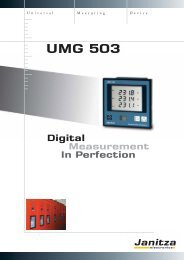
UMG 503PQM - <strong>Power</strong> <strong>Quality</strong> <strong>Monitoring</strong>Digital measurementin perfection<strong>Power</strong> analysers of the UMG 503 product family are mainly designed for use in low and mediumvoltage distribution systems. The large display in 144 x 144mm housing, the higher accuracy leveland the extended measurement range allows universal applications. Additional functions such asthe measurement of harmonics, the recording of minimum and maximum values, the relay outputs,pulse and analogue outputs, the bi-metallic strip function, password protection and many more offeran effective tool for fault analysis and for monitoring power quality.The interface and field bus features (Modbus) enable communication of the measurement data andincorporation in extensive energy management systems. The integrated logic enables the analysisof measurement data and the introduction of concrete measures.Areas of application Measurement, monitoring and controlling of electrical parameters in energy distribution systems Recording of load profiles for energy management systems Collection of energy consumption data for cost centre analysis Measurement value generator for building management systems or PLC (Modbus) <strong>Monitoring</strong> of harmonics, limit value monitoring52
▼Chapter 2<strong>Power</strong> analyserUMG 503The universal power analyserThe use of energy measurement technology in energy distributionhas moved dynamically towards digital universal measuring instrumentsin the past few years. The advantages are obvious: lowerequipment costs for more information and functionality. In addition,digital measuring technology is more accurate, even all alongthe entire lifespan.Clear cost advantages also result from the construction of the cabinetdue to lower installation costs and less wiring efforts in comparison toanalogue measuring technology. Universal measuring instruments ofthe UMG 503 product family are mainly designed for use in low andmedium voltage distribution systems.In addition to the large quantity of electrical measurement values, this series also offers a number of additional functions such as therecording of minimum and maximum values, the bi-metallic strip function, password protection and many more. Due to the largedisplay, the wide measurement range and the high accuracy level, the UMG 503 power analyser is very popular in low voltage maindistributor panels. The possibility for communication through various field buses enables incorporation in more complex energymanagement systems as well as the connection to PLC controls or central building control systems. The integrated harmonics analysisbecomes more significant with increasing network pollution (increasing THD-U values).▼Main featuresLarge measurement and display rangeA large display in 144x 144mm housingRS232, RS485 interfaceField bus: ModbusHarmonics display2 relay outputs (mechanical relay)Digital I/O and analogue outputsIntegrated logic for alarm signalsHigh reliability and long lifespanApplicationsThe UMG 503 is a digital flush-mounted measurement instrumentwhich is suitable for measuring and recording electrical parameters(True-RMS) in low and medium voltage networks. The measurementis suitable for 1- and 3-phase systems with and withoutneutral conductors. At a mains frequency of 50 Hz, the scanningfrequency of random measurements, which takes place twice persecond, is 6.4 kHz. It is characterised by the high accuracy level,the compact construction and the measurement of harmonics ineach phase.meter (kW, kVA, kvar, cos ϕ), an effective and reactive energymeter (kWh/kvarh), a clock, a frequency meter and a harmonicanalyser. This means that the planning, installation, wiring andstorage costs are significantly reduced for the UMG 503 in comparisonto analogue measuring instruments. Another advantage isthe more accurate and better legibility. Selected measurementvalues and power failure/power return are recorded in a ring bufferwith time stamp.In order to achieve the functional diversity of the universal measurementinstrument, you would need around 13 analogue unitssuch as an ampere meter, volt meter, volt meter switch, power53
UMG 503Data memoryA ring buffer for 80,000 or 320,000 measurement values (depending on the variant) is available for storing the selected average values.With the factory settings, average values of U1, U2, U3, I1, I2, I3, P1, P2 and P3 are stored using an average time of 15 minutes forapproximately 1 year for variants with 512 k RAM (approximately 3 months for types with 128k RAM).A total of six limit value windows for storing measurement values can be programmed. The upper and lower limit values can be freelyselected. The recording can take place within or outside of the range.Measurement value displays and automatic display rotationThe extremely legible LCD data field in connection with the function keys informs the user about the selected measurement values(current, low, high and average values). With the UMG 503, three measurement values can be simultaneously displayed in the LCDdata field and up to 140 data fields can be individually designed with the GridVis software. A cycle between 1 and 9999 seconds canbe set and a selection of measurement values can be made.<strong>Power</strong> values and cos ϕ Currents THD-U Voltage transformerBi-metallic strip functionThe bi-metallic strip function is recreated for the three external conductor currents. These values can be integrated in the stated times andbe recorded as highest average values.Summer/winter time switchThe following options can be selected:a) No switchoverb) Own switchover pointc) EU listed switchingEvent memoryThe following events can be registered in the event memory: Deletion of the event memory Relay outputs on/off Failure and return of the auxiliary voltage Failure and return of the measurement voltageInterfacesThe communication interfaces of the UMG 503 which are configured in accordance with the EIA RS485 standard (half duplex) supportthe Modbus RTU in integer format. The communication protocol can be selected by using the menu.In the Modbus RTU mode, baud rates from 9.6 kBit/s to 115 kBit/s are supported (depending on the design version). The registeraddresses are available to the PLC user in integer format.54
▼UMG 503Overview of product variantsThree/four-phase universal measurement instruments 50/60Hz; current transformer...1/5A;including GridVis programming and analysis softwareAuxiliary voltageInterfaces85 .. 250V AC,80 .. 370V DC40 .. 115V AC,55 .. 165V DC15 .. 55V AC,20 .. 80V DC128k RAMmemory512k RAMmemoryRelay outputPulse outputAnalogue output0(4) -20mARS 232RS 485Auxiliary input3-phase measurementTypeItem number - - - - - - - - UMG 503 L 52.07.017- - - - - - - - UMG 503 L 52.07.019- - - - - - - - UMG 503 L 52.07.022 - - - - - - - - UMG 503 LG 52.07.027- - - - - - - - UMG 503 LG 52.07.033- - - - - - - - UMG 503 LG 52.07.068 - - - - - - - - UMG 503 LS 52.07.028- - - - - - - - UMG 503 LS 52.07.074- - - - - - - - UMG 503 LS 52.07.037 - - - - - - - - UMG 503 S 52.07.008- - - - - - - - UMG 503 S 52.07.015- - - - - - - - UMG 503 S 52.07.009 - - - UMG 503 V 52.07.001- - - UMG 503 V 52.07.014- - - UMG 503 V 52.07.005 - - - UMG 503 OV 52.07.006- - - UMG 503 OV 52.07.016- - - UMG 503 OV 52.07.007 = Included - = Not possible = Option which can be supplied with the unit (each option is only possible once)Options for the units (release code) UMG 503..Relay outputs (min/max) OV 52.07.051Pulse output for effective or reactive energy OV 52.07.052Analogue output 0(4) – 20mA OV 52.07.053Auxiliary input OV 52.07.056Three-phase measurement L/LG/LS/S/OV 52.07.058GridVis softwareThe UMG 503 power analysers contains the GridVis software upon delivery. On one hand, this software enables simple and completeparameterisation of the respective measurement instruments and on the other hand, it can download the measurement value memory inthe unit where available. In GridVis, the data is stored in a database and can be processed in MS Excel for example. More informationis available in chapter 5 – “software”.56
▼Chapter 2Scope of operation and technical dataGeneral technical dataOperating voltage L-N, ACOvervoltage categoryQuadrants 4Refer to order details600V CAT IIIScanning rate 6 channel Per channel 6.4 / 7.68 kHzWeightDimensionsMounting1kgW=144mm x H=144mm x D=66.5mmFront panel installationWorking temperature -10…55 °CConnectable conductors (U/I)Single wire, multi-wire, fine-wire,0.08 - 2.5mm 2pin cable lugs, ferrule1.5mm 2Protection class (front/reverse) According to EN60529 IP 50/20Measurement rangeVoltage L-N, AC (without voltage transformer)Voltage L-L, AC (without voltage transformer)Current (transformer: x/1 and x/5 A)Frequency of mainsGrid typesMeasurement in single and multi-phase networks50…500VAC80…870VAC0.005...6A45...65HzTN, TT, (IT)1ph, 2ph, 3ph and up to 3x1phMeasurement valuesMeasurementparameterDisplay rangeMeasurement rangeat scaling factor 1L1 L2 L3SumLowestvalueAverage Maximumvalue * 1 valueDate/timeMeasurementaccuracyCurrent .. /5A 0.000 .. 9999 A 0.005 .. 6 A +-0.2 % rngCurrent .. /1A 0.000 .. 9999 A 0.005 .. 1 A +-0.2 % rngCurrent, neutral wire 0.000 .. 9999 A 0.060 .. 15 A +-0.6 % rngVoltage L-N 0.0 .. 999.9 MV 50 .. 500 V +-0.2 % rngVoltage L-L 0.0 .. 999.9 MV 80 .. 870 V +-0.2 % rngFrequency (U) 45.00 .. 65.00 Hz 45.00 .. 65.00 Hz +-0.2 % rdgEffective power +/- 0.00 W .. 9999 MW 0.05 W .. 2.5 kW +-0.5 % rngApparent power 0.00 VA .. 9999 MVA 0.05 VA .. 2.5 kVA +-0.5 % rngReactive power 0.00 kvar .. 999 Mvar 0.05 var .. 2.5 kvar kap. ind. +-0.5 % rng<strong>Power</strong> factor 0.00 kap. .. 1.00 .. 0.00 ind. 0.00 kap. .. 1.00 .. 0.00 ind. kap. ind. +-0.5 % rngEffective energy + 0.0 Wh .. 9999 GWh 0.05 Wh .. 9999 GWh *2 t1/t2 *3Effective energy - -0.0 Wh .. -9999 GWh -0.05 Wh .. -9999 GWh *2Reactive energy +/- 0.0 .. 9999 Gvarh 0.05vars .. 9999 Mvarh *2 t1/t2 *3Rng: from measurement range, rdg: from measurement value, t1: start time, t2: runtime, + purchase, - supply, *1 - integration over time: 5, 10, 15, 30 seconds, 1, 5, 10, 15, 30, 60 minutes,*2 memory period 60 minutes, *3 accuracy class according to EN61036:1996, VDE0418 part 7:May 1997, IEC1036:1996, with current transformer ../5A : class 1, with current transformer ../1A : class 2<strong>Power</strong> qualityHarmonics, 1 st to 20 th harmonics,even/uneven Current, voltage L1, L2, L3 Accuracy: ± 0.5% rngDistortion factor THD-U in % L1, L2, L3 Accuracy: ± 0.5% rngDistortion factor THD-I in % L1, L2, L3 Accuracy: ± 0.5% rngRecorder for limit value eventsYesMeasurement accuracyReactive energy kvarh Class 1Effective energy kWh Class 157
▼UMG 503PeripheryDigital inputs (auxiliary input) As a status input 1, refer to order detailsRelay outputs As a switch output 2, refer to order detailsPulse outputs1, refer to order detailsAnalogue outputs (0) 4...20mA 1, refer to order detailsPassword protectionYesSoftware GridVis Refer to chapter 5 YesCommunicationInterfacesRS 232 9.6, 19.2, 38.4 kbps Yes, refer to order detailsRS 485 9.6, 19.2, 38.4, 57.6, 115.2 kbps, 1.5 Mbs Yes, refer to order detailsProtocolsModbus RTU Up to 115.2 kbps YesPLC communication example .. 31 units (up to 255 units can be added using star repeater)ModbusRS485PC communication example .. 31 units (can be extended up to 255 units by star repeater)SoftwareRS232RS485Com server (TCP/IP) example .. 31 units per ComServerfor local networksMax. 57600 baudSoftwareRS485Ethernet(TCP/IP)100BaseTNote: the ComServer is only suitable for a localnetworkFibre optic connection example .. 31units per lineSoftwareRS232RS485RS485fibreoptic58
▼Chapter 2UMG 503DimensionaldrawingConnection illustrationSwitchboard cut-out139 x 139mmAll dimensions stated in thisdrawing are in mm.▼Typical connection option(Item number 52.07.001)59
UMG 505PQM - <strong>Power</strong> <strong>Quality</strong> <strong>Monitoring</strong><strong>Power</strong> analysis, LONand I/O diversity<strong>Power</strong> analysers of the UMG505 product family are mainly designed for use in low and mediumvoltage distribution systems. Due to the additional communication options using LON, this poweranalyser is often used in building management. The large number of digital and analogue inputs andoutputs (4 DI, 5DO, 4AO) enables the incorporation in monitoring systems, control tasks, informationreports, the communication of measurement data (e.g. energy consumption) at a controlpoint and incorporation in an extensive energy management system. Additional functions such as themeasurement of harmonics, the recording of minimum and maximum values, the relay output, pulseand analogue outputs, the bi-metallic strip function, password protection and many more offers aneffective tool for fault analysis and for monitoring power quality.Areas of application Measurement, monitoring and control of electrical parameters in energy distribution systems Recording of load profiles for energy management systems (cost centre data collection) Data logging (water, gas, cooling, electrical ...)Measurement value generator for central building control systems or PLC<strong>Monitoring</strong> of harmonics, limit value monitoringControl tasks e.g. depending upon achieved measurement values or limit values60
▼Chapter 2<strong>Power</strong> analyserUMG 505 power analyserLON for building services, analogue I/Osfor control tasksThe use of energy measurement technology in energy distributionhas moved dynamically towards digital universal measuringinstruments in the past few years. The advantages are obvious:lower equipment costs for more information and functionality. Inaddition, digital measuring technology is more accurate, even allalong the entire lifespan.Clear cost advantages also result from the construction of the cabinetwhich results in lower installation costs and less wiring efforts incomparison to analogue measuring technology. Universal measuringinstruments of the UMG505 product family are mainly designedfor use in low and medium voltage distribution systems.In addition to the large quantity of electrical measurement values, this series also offers a number of additional functions such as therecording of minimum and maximum values, the bi-metallic strip function, password protection and many more. Due to the LONfield bus, the UMG 505 is starting to find more applications in building services. The large number of digital and analogue inputsand outputs offers a variety of communication possibilities and allow connection to PLC controls and independent control tasks. Theintegrated harmonics analysis becomes more significant with increasing network pollution (increasing THD-U values).▼Main featuresLON bus, Modbus RTUHarmonics display4 analogue outputs4 digital inputs, 5 digital outputsIntegrated logic for control tasks and alarm signalsWeekly time switch with 100 channelsApplicationsThe UMG 505 is a digital flush-mounted measurement instrumentwhich is suitable for measuring and recording electrical parameters(True-RMS) in low and medium voltage networks. The measurementdevice is suitable for 1- and 3-phase systems with and withoutneutral conductors. At a mains frequency of 50 Hz, the scanningfrequency of random measurements, which takes place twiceper second, is 6.4 kHz. It is characterised by the high accuracylevel, the compact construction and the measurement of harmonicsin each phase.effective and reactive energy meter (kWh/kvarh), a clock, a frequencymeter and a harmonic analyser. This means that the planning,installation, wiring and storage costs are significantly reducedwith the UMG 505 in comparison to analogue measuring instruments.Another advantage is the more accurate and better legibility.Selected measurement values and power failure/power returnare recorded in a ring buffer with time stamp.In order to achieve functional variety of the UMG 505, you wouldneed around 13 analogue units such as an ampere meter, voltmeter, volt meter switch, power meter (kW, kVA, kvar, cos ϕ), an61
UMG 505Measurement value displays and automatic display rotationThe extremely legible LCD display in connection with the function keys informs the user about the selected measurement values(actual, low, high and average values). With the UMG 505, three measurement values can be simultaneously displayed in the LCDdata field and up to 140 data fields can be individually designed with the GridVis software. A cycle between 1 and 9999 secondscan be set for measurement value rotation and a selection of measurement values can be made.MemoryThe memory of the UMG 505 is split into three areas: the event memory, the lowest and highest memory and the ring buffer.Event memoryThe following events can be stored in the event memory with time and date:Deletion of the event memoryChanges to the digital inputFailure and return of the auxiliary voltageFailure and return of the measurement voltageUp to a maximum of 9999 events can be stored. The data can only be read out with the PC and the GridVissoftware.Ring bufferThe following can be selected for storage in the ring buffer:Average of measurement valuesThe fixed energy metersWhen storing the average values of U1, U2, U3, I1, I2, I3, P1, P2 and P3 using an average time of 15 minutes, the memory issufficient for a period of 1 year. A total of six limit value windows for storing measurement values can be programmed. The upperand lower limit values can be freely selected. The recording can take place within or outside of the range.Summer/winter time switchThe following options can be selected: No switchover Own switchover point EU listed switchingWeekly time switchThe time switch in the UMG 505 has 100 time channels. Each time switch channel specifies a period of time. The period oftime is specified by the start-up point and the switch off point. The start and stop points are defined by weekdays, hour andminutes. Each time switch channel can simultaneously control a time switch output and select a consumption meter. A timeswitch output can be allocated to a “digital output” when programming the digital outputs.62
▼Chapter 2Scope of operationPulse outputsThe five digital outputs in the UMG 505 can be assigned as pulseoutputs. The minimum pulse length is 50ms and the maximumfrequency is 10Hz.Pulse inputDigital input 4 can also be used as a pulse meter input for theeffective energy measurement (max 20Hz).Digital inputsThe 4 optical coupler inputs are illustrated on the internal inputs1 to 4. The UMG 505 has a total of 20 internal inputs. The eightinputs from the LON bus interface (option) are illustrated on theinternal inputs 5 to 12 and eight inputs from the MODBUSinterface (option) are illustrated on the internal inputs 13 to 20.The status of the digital inputs 1-4 can be called up using theserial interface.Each input channel can simultaneously switch a energy counterand synchronise the internal clock.Two of each of the digital inputs can be linked with each otherusing AND. The results can be allocated to an input channel.Each digital input 1 to 4 is allocated to an event counter (1-3max. 1Hz). If one of the digital inputs (1 to 4) is allocated a function,with the exception of pulse value, all changes are recordedwith the date and time stamp in the event memory.Digital outputThe UMG 505 has five digital transistor outputs. These outputsare marked on the display with out1 to out5. Each of these outputscan be allocated to a different data source. There are up to 5different data sources which can be selected:Limit value outputsTimes switch outputsLON bus (option)MODBUS (option)Energy meterEach data source can only be allocated to one output. If an outputis allocated to a consumption meter, the output works as a pulsegenerator.The signals from all data sources (except the consumption meter)can also be generated as inverted signals.Analogue outputsThe UMG 505 has 4 analogue outputs. The analogue outputshave common ground and are galvanically isolated from the otherinputs and outputs in the UMG 505. An external auxiliary voltageof 20V to 30V DC is required to operate the analogue outputs.The sources for analogue outputs are:InterfacesMeasurement valuesValues which are sent to theUMG 505 through Modbus.Depending upon the product variant, the UMG 505 is equippedwith an RS485 LON and/or an RS232 interface. The RS232interface serves as a peer-to-peer connection e.g. as a connectionbetween the UMG 505 and a laptop. The protocol Modbus RTUis available through the RS485 which is used to network theUMG 505. The LON interface is frequently used in central buildingcontrol systems in order to incorporate the UMG 505 inbuilding automation.Limit value monitoringFive limit value outputs can be programmed to monitor themeasurement values. Each limit value output can be allocated toup to 3 comparators (A, B, C). The following can be programmedfor each comparator:2 limit values and 2 measurement values or2 limit values and 1 measurement value or1 limit value and the minimum start-up timeAny limit value violations established by a limit value output isregistered in the event memory with a record of the time and canalso be issued on a “digital output”.63
▼Chapter 2Product variants and technical dataOverview of product variantsAuxiliary voltageInterfaces85 .. 265V AC,80 .. 370V DC40 .. 115V AC,55 .. 165V DC15 .. 55V AC,20 .. 80V DC512k RAM memory4 digital inputs5 digital outputs4 passive analogueoutputs 0(4) – 20mALONRS 232RS 4853-phase measurementTypeItem number - - - - UMG 505 MOD 52.10.004- - - - UMG 505 MOD 52.10.005- - - - UMG 505 MOD 52.10.006 - - - - UMG 505 MOD 52.10.007- - - - UMG 505 MOD 52.10.008- - - - UMG 505 MOD 52.10.009 - - - UMG 505 LON 52.10.001- - - UMG 505 LON 52.10.002- - - UMG 505 LON 52.10.003 - - - UMG 505 LON 52.10.013- - - UMG 505 LON 52.10.015- - - UMG 505 LON 52.10.016 = Option - = Not possible = IncludedGeneral technical dataOperating voltage L-N, ACOvervoltage categoryQuadrants 4Refer to order details600V CAT IIIScanning rate 6 channels Per channel 6.4 kHz / 7.68 kHzWeightDimensionsMounting1kgW= 144mm x H=144mm x D=66.5mmFront panel installationWorking temperature range -10…55 °CConnectable conductors (U/I)Single wire, multi-wire, fine-wire,pin cable lugs, ferrule0.08 - 2.5 mm 21.5 mm 2Protection class (front/reverse) According to EN60529 IP 50/20Measurement rangeVoltage L-N, AC (without voltage transformer)Voltage L-L, AC (without voltage transformer)Current (transformer: x/1 and x/5 A)Frequency of mainsGrid typesMeasurement in single and multi-phase networks50…500VAC80…870VAC0.005...6 A45...65 HzTN, TT, (IT)1ph, 2ph, 3phand up to 3x1ph65
▼UMG 505Measurement valuesMeasurementparameterDisplay rangeMeasurement rangeat scaling factor 1L1 L2 L3 SumLowestvalueAverage Maximumvalue * 1 valueDate/timeMeasurementaccuracyCurrent .. /5A 0.000 .. 9999 A 0.005 .. 6 A +-0.2 % rngCurrent .. /1A 0.000 .. 9999 A 0.005 .. 1 A +-0.2 % rngCurrent, calculated in neutral 0.000 .. 9999 A 0.060 ..1 5 A +-0.6 % rngVoltage L-N 0.0 .. 999.9 MV 50 .. 500 V +-0.2 % rngVoltage L-L 0.0 .. 999.9 MV 80 .. 870 V +-0.2 % rngFrequency (U) 45.00 .. 65.00 Hz 45.00 .. 65.00 Hz +-0.2 % rdgEffective power +/- 0.00 W .. 9999 MW 0.05 W .. 2.5 kW +-0.5 % rngApparent power 0.00 VA .. 9999 MVA 0.05 VA .. 2.5 kVA +-0.5 % rngReactive power 0.00 kvar .. 999 Mvar 0.05 var .. 2.5 kvar cap ind. +-0.5 % rng<strong>Power</strong> factor 0.00 kap. .. 1.00 .. 0.00 ind. 0.00 kap. .. 1.00 .. 0.00 ind. cap. ind. +-0.5 % rngEffective energy + 0.0 Wh .. 9999 GWh 0.05 Wh .. 9999 GWh *2 t1/t2 *3Effective energy - -0.0 Wh .. -9999 GWh -0.05 Wh .. -9999 GWh *2Reactive energy +/- 0.0 .. 9999 Gvarh 0.05vars .. 9999 Mvarh *2 t1/t2 *3Harmonic rate THD U,I 0.0 .. 100 % 0.0 .. 100 % +-0.5 % rngPartial harmonic I, 2 nd to 20 th 0.000 A .. 9999 A 0.005 A .. 5A (1 A) +-0.5 % rngPartial harmonic U, 2 nd to 20 th 0.0 V .. 99.99 kV 0.000 V .. 9999 V +-0.5 % rngRng: of measurement range, rdg: of measurement value, t1: start time, t2: runtime, + purchase, - supply*1 - integration over time: 5, 10, 15, 30 seconds, 1, 5, 10, 15, 30 and 60 minutes*2 - memory period – 60 minutes*3 - accuracy class according to EN61036:1996, VDE0418 part 7: May 1997, IEC1036:1996 with current transformer ../5A: class 1 with current transformer ../1A: class 2<strong>Power</strong> qualityHarmonics, 1 st to 20 th harmonics,even/unevenCurrent, voltage L1, L2, L3Accuracy: ± 0.5% rngDistortion factor THD-U in % L1, L2, L3 Accuracy: ± 0.5% rngDistortion factor THD-I in % L1, L2, L3 Accuracy: ± 0.5% rngRecorder for limit value eventsYesFeaturesMemory sizeClockWeekly time switch512kB± 3 minutes per monthYes, 100 channelsPeripheryDigital inputs As a status input or pulse input 4Digital outputs As a switch output or pulse output 5Analogue outputs 0(4)…20mA 4Password protectionYesSoftware GridVis Refer to chapter 5 YesCommunicationInterfacesRS 232 9.6, 19.2, 38.4 kbps Yes, refer to order detailsRS 485 9.6, 19.2, 38.4, 57.6, 115.2 kbps Yes, refer to order detailsLONYes, refer to order detailsProtocolsModbus RTUYesLonTalkYes, refer to order details66
▼Chapter 2UMG 505DimensionaldrawingConnection illustrationSwitch board cut-out:139x139 mmAll dimensions stated in thisdrawing are in mm.Illustration: option with LON▼Typical connection optionsConsumers67
UMG 507PQM - <strong>Power</strong> <strong>Quality</strong> <strong>Monitoring</strong>Continuous measurementsand the Ethernet<strong>Power</strong> analysers of the UMG 507 product family are suitable for use at all network levels. The continuousmeasurement enables the collection of various measurement parameters, the identification ofshort-term interruptions, a fault recorder function and harmonic analysis. Extensive communicationoptions e.g. Ethernet (TCP/IP), Modbus, Profibus, RS232, RS485, HTTP, SMTP, UTP or DNSallow affordable and quick integration in existing communication networks. Worldwide access to theembedded web server can be gained through a web browser. This means that the extensive opportunitiesoffered by the UMG 507 are available without any additional software. The large number ofdigital and analogue inputs and outputs enable incorporation in monitoring systems, control tasks,information reports, the communication of measurement data (e.g. energy consumption) to a centralcontrol point and incorporation in extensive energy management systems. Extensive logic functionsallow the analysis of measurement data and the introduction of concrete measures.Areas of applicationFor measuring, monitoring and control of electrical parameters in energy distribution systemsFor recording load profiles (energy consumption) for energy management systems(cost centre data collection)For monitoring power quality (harmonics, short term interruptions, inrush currents…)Control tasks e.g. depending upon the achieved measurement values or limit values Data logging (electricity, gas, water, cooling ...)Peak demand management (avoidance of costly and dangerous peak loads)Remote monitoring via onboard homepage68
▼Chapter 2<strong>Power</strong> analyserUMG 507 power analyserMulti-function power analyserThe use of energy measurement technology in energy distributionhas moved dynamically towards digital universal measuring instrumentsin the past few years. The advantages are obvious: lowerequipment costs for more information and functionality. Inaddition, digital measuring technology is more accurate, even allalong the entire lifespan.Clear cost advantages also result from the construction of the cabinetwhich results in lower installation costs and less wiring effortsin comparison to analogue measuring technology. <strong>Power</strong> analysersof the UMG 507 product family are designed for use at all networklevels.Due to the continuous measurement, short-term interruptions are registered and the fault recorder function provides more informationabout the event. A rapid, cost-optimised and reliable communication system can be developed through the Ethernet connection.The instrument’s own homepage offers you the opportunity to call up the data or configure the instrument directly using theembedded web server. The large number of digital and analogue inputs and outputs offers a variety of communicationpossibilities and allow connection to PLC controls and independent control tasks. The integrated harmonic analysis becomes moresignificant with increasing network pollution (increasing THD-U values).▼Main featuresContinuous measurementData collection of short-term interruptionsEthernet and embedded web serverHarmonics analysis6 digital inputs, 6 digital outputs, 2 analogue outputs, 1 analogue input1 temperature inputIntegrated logic for control tasks and alarm signals Modbus master, Ethernet/Modbus gatewayThis allows the safe identification of short-term interruptions withApplicationsThe three-phase electronic measuring instrument collects and digitalisesthe effective values of currents and voltages (True RMS) in a50/60Hz network. The integrated microprocessor calculates the electricalparameters from the sampling values. All measurement valuesare continuously measured and recorded at intervals of 200ms over10 periods (50 Hz).the fault recorder function. For short-term events, the effective valuesare recorded over 128 periods with 64 pre-trigger periods and withthe transient memory over 5 periods with 2 pre-trigger periods.The reaction time of the internal outputs is < 10ms and the externalbus outputs < 200ms.69
UMG 507GridVis softwareThe UMG 507 power analysers already contain the GridVis software upon delivery. On one hand, this software enables simple and completeparameterisation of the respective measurement instruments and on the other hand, can analyse the measurement value memory inthe unit. In GridVis, the data is stored in a database and can be processed in MS Excel for example. GridVis also allows online presentationof the measurement values. More information is available in chapter 5 – “software”.Peak demand management (Emax)The release of the Emax function for peak demand management is available as an option. More information can be found in chapter 3 –energy management.Embedded web server / e-mailWorldwide access to the UMG 507 can be gained through a web browser. In order to provide access, the web address and access authorisationsmust be set up. The complete parameterisation software is filed as an HTML page on the flash memory. The open architectureof the UMG 507 allows the user to apply own ideas to design Java-Applets and Active X-components and file them on the UMG507. Iflimit value violations or events occur, they can be automatically sent to the set up e-mail address. Data from the memory storage can besent by e-mail (attachment) at preset times and processed with the GridVis software.Protocols: HTTP, SMT, UTP, DNS, NTP, MOD TCP, Modbus over TCP, DHCP/BootP.Connection to an ISDNrouter / DSL routerThe unit can be connected to the internet using an external router (e.g. ISDN router or DSL router).The SMTP authentication enables you to store mails on the internet provider’s mailbox using the Plain/Login/Cram-MDS (newestencryption methods).Data collection and recordingThe UMG 507 has an internal memory of 256KB RAM and, depending on the version, an additionalmemory of 16 MB flash is available for continuousrecording of the measured data. This measurementvalue memory can be freely configuredwith reference to the measurement values whichare to be saved and the recording intervals. Inaddition, the highest and lowest actual values (200ms average time) can also be saved within theseintervals. The recording of events is prompted bytriggers. Events such as excess currents, under voltageor overvoltage can be safely collected from ahalf period duration. Events are recorded over 128periods as effective value recorders.70
▼Chapter 2Product variants and technical dataOverview of product variantsThree/four-phase universal measurement instruments 50/60Hz; current transformer...1/5A;including GridVis programming and analysis softwareAuxiliary voltageInterfaces85 .. 250V AC,80 .. 370V DC40 .. 115V AC,55 .. 165V DC15 .. 50V AC,20 .. 70V DC256k RAM memoryAdditional 16MBflash memory6 digital inputs6 digital outputs1 temperature input1 analogue input2 passiveanalogue outputsRS 232RS 485Ethernet 10baseTProfibus DP V0Integrated weeklytime switch clockTypeItem number - - - - - - - - UMG 507 L 52.15.004- - - - - - - - UMG 507 L 52.15.009 - - - - - - - - - - UMG 507 EL 52.15.021- - - - - - - - - - UMG 507 EL 52.15.022 - - - - - UMG 507 AD 52.15.003- - - - - UMG 507 AD 52.15.008 - - - - UMG 507 P 52.15.002- - - - UMG 507 P 52.15.007 - - - UMG 507 E 52.15.001- - - UMG 507 E 52.15.006- - - UMG 507 E 52.15.011 - - UMG 507 EP 52.15.005- - UMG 507 EP 52.15.010- - UMG 507 EP 52.15.015Unit optionsEmax function (maximum demand controller) Emax 52.15.080- = Not possible = IncludedGeneral technical dataOperating voltage L-N, ACOvervoltage categoryQuadrants 4Refer to order details600V CAT IIIMeasurement Per channel ContinuousWeightDimensionsMounting1kgW= 144mm x H= 144mm x D=66.5mmFront panel installationWorking temperature range -10…55 °CConnectable conductors (U/I)Single wire, multi-wire, fine-wire,0.08 - 2.5mm 2pin cable lugs, ferrule1.5mm 2Protection class (front/reverse) According to EN60529 IP 50/20Measurement rangeVoltage L-N, AC (without voltage transformer)Voltage L-L, AC (without voltage transformer)Current (transformer: x/1 and x/5 A)Frequency of mainsGrid typesMeasurement in single and multi-phase networks50…500VAC80…870VAC0.005...6A45...65HzTN, TT, (IT)1ph, 2ph, 3ph and up to 3x1ph73
▼UMG 507Measurement valuesMeasurementparameterDisplay rangeMeasurement rangeat scaling factor 1L1 L2 L3rng: of measurement range, rdg: of measurement value, t1: start time, t2: runtime, + purchase, - supply, *1- integration over time: 5, 10, 15, 30 seconds, 1, 5, 10, 15, 30 and 60 minutes,*2 - memory period – 60 minutes *3 - accuracy class according to DIN EN61036: 2001-01, VDE0418 part 7, IEC1036:1996 + A1: 2000SumLowestvalueMaximumaveragevalueAverage Maximumvalue * 1 valueDate/timeMeasurementaccuracyCurrent .. /(1)5A 0.000 .. 9999 A 0.005 .. /(1)6A +-0.2 % rngCurrent, N 0.000 .. 9999 A 0.060 .. 15 A +-0.6 % rngVoltage L-N 0.0 .. 999.9 MV 50 .. 500 V +-0.2 % rngVoltage L-L 0.0 .. 999.9 MV 90 .. 870 V +-0.2 % rngPos./neg./zero sequence 0.0 .. 999.9 MV 50 .. 500 V +-0.5 % rngFrequency (U) 45.00 .. 65.00 Hz 45.00 .. 65.00 Hz +-0.2 % rdgEffective power +/- 0.00 W .. 9999 MW 0.05 W .. 2.5 kW +-0.5 % rngApparent power 0.00 VA .. 9999 MVA 0.05 VA .. 2.5 kVA +-0.5 % rngReactive power 0.00 kvar .. 999 Mvar 0.05 var .. 2.5 kvar ind. +-0.5 % rng<strong>Power</strong> factor 0.00 kap. .. 1.00 .. 0.00 ind. 0.00 kap. .. 1.00 .. 0.00 ind. ind. +-0.5 % rngEffective energy + 0.0 Wh .. 9999 GWh 0.05 Wh .. 9999 GWh *2 t1/t2 Class * 3Effective energy - -0.0 Wh .. -9999 GWh -0.05 Wh .. -9999 GWh *2 1 (5A), 2 (1A)Reactive energy +/- 0.0 .. 9999 Gvarh 0.05vars .. 9999 Mvarh *2 t1/t2 Class * 31 (5A), 2 (1A)<strong>Power</strong> qualityHarmonics, 1 st to 20 th harmonics, uneven Current, voltage L1, L2, L3 Accuracy: ± 0.5% rngDistortion factor THD-U in % L1, L2, L3 Accuracy: ± 0.5% rngDistortion factor THD-I in % L1, L2, L3 Accuracy: ± 0.5% rngVoltage positive/negative/zero systemAccuracy: ± 0.5% rngShort-term interruptions 10ms yesInitial current 10ms yesRecorder for limit value eventsyesMeasurement accuracyAccuracy VA ± 0.2%Reactive energy kvarh Class 1 (5A), 2 (1A)Effective energy kWh Class 1 (5A), 2 (1A)FeaturesMemory size256kB/16MB – refer to order detailsClock± 2 minutes per monthIntegrated logic 128 links, 16 comparators YesWeekly time switch 24 channels YesPeripheryDigital inputs As a status input or pulse input 6 – refer to order detailsDigital outputs As a switch output or pulse output 6 – refer to order detailsAnalogue outputs 0(4)…20mA 2 – refer to order detailsTemperature measurement input Pt100, Pt1000, KTY83, KTY84 1 – refer to order detailsAnalogue input 0(4)…20mA 1 – refer to order detailsPassword protectionYesSoftware GridVis Refer to chapter 5 Yes74
▼Chapter 2UMG 507CommunicationInterfacesRS 232 38.4 kbps YesRS 485 (Modbus/Profibus) 9.6, 38.4, 115.2 kbps up to 1.5 Mbps (Sub D 9 pole) Yes, refer to order detailsEthernet 10 Base-T RJ45 Yes, refer to order detailsProtocolsModbus RTUYes, refer to order detailsProfibus DP V0Yes, refer to order detailsModbus gatewayYes, refer to order detailsEmbedded web server Configurable homepage Yes, refer to order detailsTCP/IPYes, refer to order detailsSMTP E-Mail Yes, refer to order detailsDHCPYes, refer to order detailsModbus TCPYes, refer to order detailsModbus over EthernetYes, refer to order detailsBootPYes, refer to order detailsNTPYes, refer to order detailsDimensionaldrawingConnection illustrationSwitchboard cut-out:139x139 mm▼All dimensions stated inthis drawing are in mm.Typical connection options (e. g. UMG 507EP)75
UMG 508PQM - <strong>Power</strong> <strong>Quality</strong> <strong>Monitoring</strong>Multifunctional <strong>Power</strong> Analyserwith Ethernet and BACnetThe <strong>Power</strong> Analyser UMG 508 is an all-rounder for the front door panel mounting. The device isequipped with a colourful graphic display with intuitive user interface. The extensive measuring functions,such as monitoring of short term interruptions, inrush currents, transients, harmonics up tothe 40th order …) are unique in this price range.Extensive communication options, such as RS485 (Modbus RTU, Profibus), Ethernet TCP / IP,BACnet, HTTP, FTP, SNMP, SMTP, SNTP, or DNS allow a cost effective and rapid integration intoexisting communication structures.The measurement is made on 4 separate current inputs, either for three phase systems with additionalmeasurements in N or PE or the measurement of 4 individual single-phase loads. The UMG 508has per each current input a separate energy counter. The very large data memory of 256 MB permitsthe logging of all readings for months even without intermediate reading.Areas of application <strong>Monitoring</strong> of a wide range of electrical and energy parameters Continuous monitoring of the power quality parameters Ethernet-Gateway for subordinate measurement devices Analysis of electrical faults and root cause analysis in case of power failures Cost centre management Remote monitoring for real estate management Usage in test facilities (e.g. in Universities)76
▼Chapter 2Main features and customer's benefitUser-friendly graphical color display with intuitiveuser interfaceThe high-resolution graphic display provides informative presentations of line graphs,FFT harmonic as bar diagram, clear display of the kWh-month values, alarm management/ event viewer with dates and time stamp, and many other features.In addition to the information content the redesign of the UMG displays focused verymuch on a user-friendly, self-explanatory and intuitive operation of the UMG 508.Modern communication architecture via Ethernet:Cost-effective, fast and safe communicationIn many cases the costs for installation and communication (e.g. peripheral equipmentfor field buses) exceed those for the respective power meters. Integration of theUMG 508 in an existing Ethernet architecture means a fast, cost- efficient and reliablecommunication. Additional interfaces enable the integration of the power analysersinto PLC or building automation systems. The use of open standards offers greatflexibility to the user.▼Modbus Gateway:Easy integration of devices withoutEthernet interfaceWith the Modbus Gateway function of UMG 508 you can connect lesssophisticated Modbus RTU meters to Ethernet. The UMG 508 can be used simultaneouslyas a gateway for sub-meters or prior instruments existing within the installation.Each instrument with a Modbus RTU interface can be connected, if its data formatand function codes correspond. Data can be scaled and labelled.Highspeed ModbusThe UMG 508 series can transfer data via RS485 interface with a speed of up to921.6 kB/s among each other device of this series.Alarm management:E-mail and homepage inform you, wherever you are...Who would not agree? Just leaving the building the first call arrives about certain problemsin production, computer failure, energy breakdown...By using a webbrowser and IP address you have direct access to the extremely powerfulhomepage of your UMG 508. You get detailed information about the actual conditionof your powergrid from the homepage. Online data as well as historical data andgraphs of events are available. Via homepage you can directly calculate the costs ofyour energy consumption and export it into a CSV-file or print it out.Alternatively, an e-mail informs you, if overload occurs, short-term interruptions disruptyour production process, harmonics reduce the life expectancy of your technicalequipment... The applications are ceaseless.77
▼Kapitel 2<strong>Power</strong> analyserOverview of product variants UMG 508Supply voltageInterfaces95...240V AC,135...340V DC44...130V AC48...180V DC20...50V AC20...70V DC4 voltage and4 current inputsAdditional memory256 MB Flash8 digital inputs5 digital outputsRS 485*Ethernet 100baseTProfibus DP V0*7 freely programmableapplication programmesTypeItem number UMG 508 52.21.001 UMG 508 52.21.002 UMG 508 52.21.003optionally availableApplication programme EMax function EMAX 52.16.080BACnet communication BACnet 52.16.081- = not possible = contained *1 DSUB-9 connectorFeaturesMemory256 MBClock+/- 1 min per monthIntegrated logic Programming language Jasic ®Operating hours counteryesWeekly switching clock Jasic ®PeripheralsDigital inputs as status or pulse input 8Digital outputs as switching or pulse output 5Password protectionyesMaximum demand control optional 64 channels yesSoftware GridVis yes79CommunicationInterfacesRS 485* 9.6, 19.2, 38.4, 76.8, 115.2, 921.6 kbps yesProfibus DP* Sub D9-pole up to 12 Mbps yesEthernet 10/100 Base- TX RJ-45 connector yesProtocolsModbus RTUyesProfibus DP V0yesModbus TCPyesModbus over TCPyesModbus gatewayyesHTTP homepage (configurable) yesSMTP e-mail yesSNTP time synchronization yesTFTP automatic configuration yesFTP file transfer yesSNMPyesDHCPyesTCP/IPyesBACnetyes*1 DSUB-9 connector
▼UMG 508Technical dataSupply voltagesee overview of product variantsOvervoltage class600 V CATIIIQuadrants 4Continuous MeasurementyesSampling rate, 8 channels per channel 20 kHzWeight1 kgDimensionsH=144 mm x W=144 mm x D=81 mmMounting according to IEC EN60999-1/ DIN EN50022 Frontpanel mountingWorking temperature -10…55 °CConnectable wires (U/I) one wire, more wires, fine stranded wires 0,08 - 2,5 mm²cable end sleeve1,5 mm²Protection class according to EN60529 IP 20Measuring rangeVoltage L-N, AC (without VT)Voltage L-L , AC (without VT)Current (Transformer: x/1 und x/5 A)Frequency of fundamentalGridsMeasurement in grids50…500 V AC8…870 V AC0.005...6 A40...70 HzTN, TT1ph, 2ph, 3ph, 4phup to 4 times 1phMeasured valuesVoltage L1, L2, L3, L4, L1-L2, L2-L3, L1-L3 accuracy ±0.1 %Current L1, L2, L3, L4, Sum L1-L3, Sum L1-L4 accuracy ±0.2 %K-factor L1, L2, L3, L4 yesRotating current components Positive/ Negative/ Zero Phase Sequence yesReal, apparent, reactive power L1, L2, L3, L4, Sum L1-L3, Sum L1-L4 accuracy ±0.4 %Cos-phi / phase angle L1, L2, L3, L4, Sum L1-L3, Sum L1-L4 yesPhase angle L1, L2, L3, L4 yesReal energy (kWh)Reactive energy (Karh)L1, L2, L3, L4, Sum L1-L3, Sum L1-L4:- Consumed real energy (rate 1, rate 2)- Supplied real energy (rate 1, rate 2)L1, L2, L3, L4, Sum L1-L3, Sum L1-L4:- Inductive energy (rate 1, rate 2)- Capacitive reactive energyClass 0.2S (…/5 A),Class 1 (…/1 A)Class 2Reactive energy (kVAh) L1, L2, L3, L4, Sum L1-L3, Sum L1-L4 yesWave form voltage L1, L2, L3, L4 yesFrequency of mainsaccuracy ±0.1% rdgAverage valuesyesMinimum and maximum valuesyes<strong>Power</strong> qualityHarmonics, 1st- 40thCurrent, voltage, real/reactive power (±)L1, L2, L3, L4Distortion factor THD-U in % L1, L2, L3, L4 yesDistortion factor THD-I in % L1, L2, L3, L4 yesUnbalancePositive/ Negative/ Zero Phase SequenceTransients 50 μs yesInrush-currents 10 ms yesMalfunction writerShort-term interruptionsaccuracy ±(0.5% rdg + 0.05 rng)yesyesyesyes80
▼Chapter 2UMG 508Dimensional drawingConnection illustrationSide viewView from below.All measurement data in mm.Ethernet connection▼Typical connection81
UMG 511PQM - <strong>Power</strong> <strong>Quality</strong> <strong>Monitoring</strong>Class A power quality analyseraccording to IEC61000-4-30The UMG 511 power quality analyser is particularly suitable for monitoring power quality accordingto standards such as the EN 50160. All power quality parameters are collected and analysed e.g.flicker, short term interruptions with fault recorder function, transients, harmonics up to the 63 rdand inrush currents etc. Extensive communication possibilities e.g. RS 485 Modbus, Profibus,Ethernet (TCP/IP), BACnet, HTTP, FTP, SMTP, SNTP, DNS ... allow cost effective and rapid integrationin existing communication networks. Worldwide access to the embedded web server can begained through a web browser. The GridVis software included in the content of delivery allows extensiveanalysis just by the click of a button.Areas of application Continuous monitoring of the power quality e.g. EN 50160Ethernet gateway for subordinate measurement pointsAnalysis of electrical faults for network problems <strong>Monitoring</strong> of the internal distribution network according to EN 61000-4-7, 4-15, 4-30Report generator for EN 50160 analysisRemote control82
▼Chapter 2<strong>Power</strong> quality analyserUMG 511 power quality analyserAdded value with additional functionsThe UMG 511 power quality analyser serves for the purpose ofcontinuous monitoring of the power quality e.g. in accordancewith EN 50160. This serves for the purpose of monitoring the supplypower quality from the energy supply side. The UMG 511 canalso be used in applications for failure analysis on the consumerside and is also used as a preventative measure for network perturbations.A rapid, cost-optimised and reliable communicationsystem can be developed through the Ethernet connection. Theinstrument’s own homepage offers you the opportunity to call upthe data or configure the instrument directly using the embeddedweb server.The large number of digital and analogue inputs and outputs offer a variety of communication systems possibilities and allowsconnection to PLC systems and independent control tasks. The GridVis analysis software represents a fundamental part of the standarddelivery. The GridVis can be used to practically trigger analysis in accordance with EN 50160 with the click of a button. Thepresentation of online data and the analysis of historical data is also a benefit for finding the root cause of network problems.▼Main features Measurement of power quality according to DIN EN 61000-4-30, Class A Fourier analysis 1 st to 63 rd harmonic for U-LN, U-LL, I, P (consumption/supply) and Q (ind./cap.) Measurement of harmonics and interharmonics (U-LN, U-LL, I) according to DIN EN 61000-4-7 Analysis and evaluation according to DIN EN 50160 with the contained programming and analysissoftware GridVis Flicker measurement according to DIN EN 61000-4-15 Measurement in TN and TT grids (600V CATIII) 4 voltage measuring inputs, 4 current measuring inputs Continuous sampling of voltage and current inputs with 20kHz Recording of more than 2000 different measurement parameter per measuring cycle (200ms) Detection of transients >50µs and storage with up to 16.000 samples Data logger / Event memory (256MB Flashdisk) 8 digital inputs and 5 digital outputs Profibus DP/V0 alternatively RS 485 (Modbus RTU, Modbus-Master, optional BACnet) Ethernet (Web-Server, E-Mail, optional BACnet) Programming of customer specific applications in Jasic ®ApplicationsThe power quality analyser which is equipped with 4 current andvoltage inputs collects and digitalises the effective values (TrueRMS) from currents and voltages in 40-70Hz (15-440Hz) networks.The integrated microprocessor calculates the electrical parametersfrom the sampling values. The relevant voltage can be definedas a phase-neutral or a phase-phase voltage for measurement ina three-phase system. The voltage serves the UMG 511 as a refe-rence voltage for harmonic measurement, transient and eventrecording and for the flicker meter. A nominal current can be setusing this for the measurement of electrical current events. The 4thcurrent and voltage input represents a separate measurementsystem. However, it is generally used for measuring the current inthe neutral or PE conductor or used for measuring a voltage differencebetween N and PE.83
UMG 511Display examplesThe backlighted active matrix display (5,7“) of the UMG 511 enables the presentation of measurement values in numerical form,as a bar chart or as a line graph. Selected displays can automatically be displayed in alternation (automatic display rotation). Theinstrument is programmed using userfriendly clear text menus or the GridVis software.Example of a UMG 511 connection illustrationMain measurementMeasurement in a four-phase network with mainmeasurement and auxiliary measurementThe UMG 511 has 4 measurement channelsfor current and voltage. The first three channels(main measurement) are intended for use in athree-phase system.Auxiliary measurementThe auxiliary measurement can be used formeasurement in a single-phase or symmetricalthree-phase system. Alternatively, the currentinput can be allocated to the three-phasesystem of the main measurement for measuringthe neutral-conductor current. For example,the voltage input could then be used for recordingthe voltage between the neutral conductorand PE. The auxiliary measurement providesall measurement parameters like in the mainmeasurement (current, voltage, power, harmonics,transients, events and flicker).84
▼UMG 511Dimensional drawingConnection illustrationView from below.All measurement data in mm.Ethernet connectionSide viewTypical connection86
▼Chapter 2Product variants and technical dataOverview of product variants UMG 511Three/four phase power quality analysers; current transformer .../1/5a; including GridVis programming and analysis softwareSupply voltageInterfaces95...240V AC,135...340V DC44...130V AC,48...180V DC20...50V AC,20...70V DC4 voltage and4 current inputsMemory256 MB Flashdigital inputsdigital outputsRS 485Ethernet 100baseTProfibus DP V0TypeItem number 8 5 UMG 511 52.19.001 8 5 UMG 511 52.19.002 8 5 UMG 511 52.19.003Options (for all versions)Emax function application program (peak demand management) Emax 52.16.080BACnet communication BACnet 52.16.081- = not possible = containedGeneral technical dataSupply voltage L-N, ACOvervoltage categoryQuadrants 4Continuous measurementRefer to product variant overview600V CATIII8 channel scanning rate Per channel 20 kHzWeightDimensionsyes1kgL=144mm x W=144mm x H=81 mmMounting According to IEC EN 60999-1/DIN EN 50022 Front panel mountingWorking temperature range -10…50 °CConnectable conductor (U/I) Single wire, multi-wire, fine-wire 0,08 - 2,5 mm²pin cable lugs, ferrule1,5 mm²Protection class According to EN 60529 IP 50 front /IP 20 rearMeasurement rangeL-N voltage, AC (without voltage transformer) Free voltage transformer settings 5 …500 VACL-L voltage, AC (without voltage transformer) Free voltage transformer settings 8…870 VACCurrent (transformer: x/1 and x/5A)0,005..6 AFrequency of mains40 ..70 HzNetworksTN, TTMeasurement in single/multi-phase networks1 ph, 2 ph, 3 ph, 4 phPeripheryDigital inputs Status, logic or pulse input 8Digital outputs Switch logic output or pulse output 5Password protection Multilevel yesPeak load management Optional 64 channels jaSoftware GridVis jaFeaturesMemory256 MBClock+/- 1 min per monthIntegrated logic Programming language Jasic ®Operating hour meteryesWeekly time switch Jasic ®87
▼UMG 511Measurement valuesVoltage L1, L2, L3, L4, L1-L2, L2-L3, L1-L3 Accuracy ±0.12%Current L1, L2, L3, L4 ±0.2%Calculated sum current ±0.56%K-factor L1, L2, L3, L4 yesThree-phase current components Positive/ Negative/ Zero Phase Sequence yesEffective, reactive and apparent power L1, L2, L3, L4, Sum L1-L3, Sum L1-L4 Accuracy ±0.2 % acc. EN 61557-12:2008Cos-phi, power factor L1, L2, L3, L4, Sum L1-L3, Sum L1-L4 yesPhase angle L1, L2, L3, L4 yesEffective energy (kWh)Reactive energy (kvarh)L1, L2, L3, L4, Sum L1-L3, Sum L1-L4:- Purchased effective energy (tariff 1, tariff 2)- Supplied effective energy (tariff 1, tariff 2)L1, L2, L3, L4, Sum L1-L3, Sum L1-L4:- Inductive reactive power (tariff 1, tariff 2)- Capacitive reactive powerClass 0.2S (…/5A),Class 0.5S (…/1A)Apparent energy (kVAh) L1, L2, L3, L4, Sum L1-L3, Sum L1-L4 yesCurrent/voltage wave form L1, L2, L3, L4 yesFrequency of mains Accuracy ±0.01%Average valueyesMinimum and maximum valuesyesClass2<strong>Power</strong> quality, Class A, according to EN61000-4-30Harmonics order, 1 st to 63 rdVoltage L1, L2, L3, L4Class 1 acc. EN61000-4-7Harmonics, even/oddInterharmonics Current, voltage L1, L2, L3, L4 yesDistortion factor THD-U in % L1, L2, L3, L4 yesDistortion factor THD-I in % L1, L2, L3, L4 yesPositive/negative/zero systemyesActual flicker value L1, L2, L3, L4 yesShort-term flicker value L1, L2, L3, L4 yesLong-term flicker value L1, L2, L3, L4 yesTransients 50 μs yesTrigger events 10 ms yesInrush currents 10 ms yesEvent recorderyesCommunicationInterfacesRS 485 9.6, 19.2, 38.4, 76.8, 115.2, 921.6 kbps yesProfibus DP Plug, sub D 9-pole up to 12 Mbps yesEthernet 10/100 Base- TX RJ-45 sockets yesProtocolsModbus RTUyesProfibus DP V0yesModbus TCPyesModbus over TCPyesModbus gatewayyesHTTP Homepage (configurable) yesSMTP E-Mail yesSNMPyesSNTP Time synchronisation yesTFTP Automatic configuration yesFTP File Transfer yesDHCPyesBACnet / IP or MSTPyes, option88
▼▼Chapter 3<strong>Power</strong> ManagementAn overview of DIN rail kWh-metersPage 91Electronic pulse output – energy meter, EM-seriesPage 93- Modbus, M-Bus, EIB-KNX - communication module- 2 tariffs- 4 quadrant measurement- With and without MID (Measuring Instruments Directive)- Up to 125A direct measurementElectronic pulse output – energy meter, H-seriesPage 97- Direct measurement or with current transformer- SO interface pulse output- Mounting on 35mm DIN rail- 7 digit LCD display- Calibrated/non-calibratedPeak demand management systems UMG 507Emax- For limiting peak loads- Up to 32 load shedding stages- Including UMG 507 power analyser with continuous measurement- RS232, RS485, Modbus, Ethernet (optional Profibus)Data logger ProData ®- Collection and storage of counter values, operational statuses andprocess data- 16 digital inputs- 64 bit counter- 128 programmable comparators- RS232, RS485, modem, LON, Modbus, Modbus-masterPage 100Page 10689
PM - <strong>Power</strong> ManagementPM - <strong>Power</strong> ManagementProfessional energy management considers aspects such as peak demand management, energy datacollection and cost centre management. With the UMG 507Emax and ProData ® product groupsand state-of-the-art pulse output energy meters, the energy supply for your company can be activelycontrolled with regard to power peaks and energy consumption.The electricity consumption and electricity costs can,therefore, be sustainably reduced. The ProData ®series enables you to have a transparent invoicingsystem within the company and monitor theindividual cost centres with separate invoicing.This improvement to cost transparency enablesthe respective allocation to cost centres. This isespecially important for accurate determinationof the costs for your products and servicesand for transferring electricity costs toyour end consumers.90
PM - <strong>Power</strong> ManagementElectronic energy metersElectronic energy meter with pulse outputElectronic energy meters are measuring instruments which are used to determine energy consumptionof electrical loads. The meters can either be used for direct connection or for current transformermeasurements. Typical areas of application are in the field of energy management for cost centreanalysis, as a measurement value generator for PLC controls or in central building control systems.Electronic meters should be calibrated and sealed for invoicing purposes in order to guarantee conti -n uous accuracy and to protect the meter from misuse or unintended reprogramming.92
▼Chapter 3The EM series energy meterAreas of applicationElectronic energy meters are mainly used for collecting data ofeffective and reactive energy consumption. Their standard area ofapplication is in the field of energy management for cost centreanalysis. There are various communication possibilities available inorder to avoid time-consuming manual readings at site. The effectivepulses can be connected via two impulse outputs e.g. DDC,PLC, SCADA systems or the data logger ProData ® . In the area ofcentral building control systems the protocols M-Bus, EIB-KNXand Modbus RTU are available through additional communica -tion modules which read the actual meters using an optical interfaceand which provide the respective value on the field busthrough the interface. The selection of additional values such asvoltage, current, power, power factor and frequency together witheffective and reactive energy are available on the bus cable throughthe communication modules. For consumption data collection, theEM meters can also be used as instruments for sub-metering for theUMG604 through Modbus RTU.▼Main features Communication modules: Modbus, M-Bus, EIB-KNX Four quadrants measurement Direct measurement up to 125A or through current transformer 2 tariffs With and without MID calibration Class 1 Sealed clamp coversMeasurement values: effective energy,reactive energy, effective power, reactive powerApplicationsThe electronic energy meters of the EM series are suitable for themeasurement of effective- and reactive-energy consumption.Measurement is laid out for a 1- and 3- phase system with a voltageof L-N 184-276VAC. The current inputs are designed for directconnection or for measurement through current transformers.Installation is undertaken on DIN-rails, whereby the extremelycompact construction is of particular value. There are two versionsavailable: a non-calibrated version and a calibrated version (MID).All meters in the EM series can be sealed. The effective and reactiveenergy is available in two tariffs and in four quadrants. The accuracyof the meters is class 1 for effective energy and class 2 for reactiveenergy.Data collection and recordingAll meters store the counter values in non-volatile memories. The meter reading cannot be reset in the calibrated version. In the noncalibratedversion the readings can be reset. The current transformer ratio is fixed (5:5) for calibrated meters.93
Product variants andtechnical dataOverview of product variantsTypes EM1-80 EM3-80 EM3-125 EM3-5without MID EM1-80 (without MID) EM3-80 (without MID) EM3-125 (without MID) EM3-5 (without MID)Item number 14.01.301 14.01.320 14.01.330 14.01.310with MID EM1-80 (MID) EM3-80 (MID) EM3-125 (MID) EM3-5 (MID)Item number 14.01.302 14.01.321 14.01.331 14.01.311General technical dataOperating voltage 184…276VAC 184…276VAC 184…276VAC 184…276VACDimensions [mm] W= 36x H= 90x D=70 W= 72 x H= 90 x D= 70 W= 108 x H= 90 x D= 70 W= 72 x H= 90 x D= 70Width in units 2 4 6 4Working temperature -10…+55°C -10…+55°C -10…+55°C -10…+55°CStorage temperature -25…+70°C -25…+70°C -25…+70°C -25…+70°CProtection class (front/clamps) IP 51/20 IP 51/20 IP51/20 IP51/20Max connectable conductorsCurrent 35mm 2Current 35mm 2Current 50mm 2Current 6mm 2Voltage 2.5mm 2 Voltage 2.5mm 2 Voltage 2.5mm 2 Voltage 2.5mm 2Measurement rangeVoltage L-N 184…276VAC 184…276VAC 184…276VAC 184…276VACVoltage L-L - 319…478VAC 319…478VAC 319…478VACCurrent 0.025…80A 0.025…80A 0.12…125A 0.05…6A (…/5A)Frequency, mains 50Hz 50Hz 50Hz 50HzMeasurement 1-phase 3-phase 3-phase 3-phaseMeasurement mode Direct Direct Direct CTsMeasurement valueEffective energy Class 1 Class 1 Class 1 Class 1Reactive energy Class 2 Class 2 Class 2 Class 24 quadrants Yes Yes Yes Yes2 tariffs Yes Yes Yes YesEffective-, reactive-powerdisplayYes Yes Yes YesPeripheryPulse outputs 2 2 2 2Pulse value 10 Imp/kWh 10 Imp/kWh 10 Imp/kWh 1/10/100 Imp/kWhPulse length 100 ± 5ms 100±5ms 100 ± 5ms 100±5msDigital input 1 1 1 1Optional communication modulesModbus RTU / ASCII Baud rate: up to 115kBaudTypes:Modbus RTU / ASCII (Basic) Applicable parameters: Wh, kvarh Item number: 14.01.400Modbus RTU / ASCII (Full) Applicable parameters: Wh, kvarh, V, A, Hz, cosphi, kW, kvar Item number: 14.01.410M-BusTypes:Baud rate: 300…9600BaudM-Bus (Basic) Applicable parameters: Wh, kvarh Item number: 14.01.401M-Bus (Full) Applicable parameters: Wh, kvarh, V, A, Hz, cosphi, kW, kvar Item number: 14.01.411EIB-KNXTypes:Baud rate: 9600BaudEIB-KNX (Basic) Applicable parameters: Wh, kvarh Item number: 14.01.40294
▼Chapter 3The EM series energy metersEM1-80 – single-phase energy meterDimensional drawingCircuit diagramSealable clampterminalThree-phase energy meterDimensional drawingCircuit diagramdirectmeasurementwith currenttransformersAll dimensions stated in this drawing are in mm.Sealable clamp terminalInformation for connecting meters with CTsA 6A fuse on L1 is recommended to protect the cables. Current transformers mustnot be operated with open clamps because dangerously high voltages can occur.Failure to observe this information can lead to injury to persons and damage toproperty. Furthermore, CTs can be thermally overloaded.95
Module technologyCommunication modules – width is 1 unit for DIN-rails (35mm)M-Bus moduleDimensional drawingSide infrared interfacefor communication tothe energy meterLED operation controlMains electricity supplyModbus RTUandASCII moduleModbus connectionDimensional drawingSide infrared interfacefor communication tothe energy meterLED operational controlMains electricity supplyEIB-KNX moduleEIB-KNX interfaceDimensional drawingLED operational controlSide infrared interfacefor communication tothe energy meterReset buttonAll dimensions stated in these drawings are in mm.96
▼▼Chapter 3The H series electronic energy metersAreas of applicationElectrical energy meters are used to collect effective energy data.Their standard area of application is in the field of energy managementfor cost centre analysis. A pulse output is available in order toavoid time-consuming manual readings on site.The effective pulses can be connected via pulse output to e.g.DDC, PLC, SCADA systems or the data collection instrumentProData ® .ApplicationsThe electronic energy meters of the H series are suitable for themeasurement of effective energy. Measurement is laid out for a 1-and 3-phase system with a voltage of L-N 207-253VAC. The currentinputs are designed for direct connection or for measurementthrough a current transformer. The meter is installed on a DINrail.The accuracy level of the meter is class 1.Main featuresDirect measurement up to 65A or through a current transformer Class 1S0 interface pulse outputInstallation on 35mm DIN rail7 digit LCD display“In operation” modeData collection and displayAll meters store the energy values in non-volatile memories.The diagram on the right side shows the call-up possibilities for thevarious data.Display test –all segmentsactivatedCurrent transformerratio (only for CTmeters)Currentenergy value= Briefly flashes on and offwith an external light97
Product variants andtechnical dataOverview of product variantsItem number(non-calibrated instrument)Item number(calibrated instrument)WH6165 DVH3113 MDVH310614.01.020 14.01.021 14.01.02214.01.023 14.01.024 14.01.025General technical dataWH6165 DVH3113 MDVH3106Operating voltage 207…253VAC 207…253VAC 207…253VACDimensions [mm] W= 36 x H= 106 x D= 61,1 W= 125 x H= 96 x D= 66 W= 125 x H= 96 x D= 66Width in units 2 7 7Working temperature -20…+55°C -20…+55°C -20…+55°CStorage temperature -25…+70°C -25…+70°C -25…+70°CProtection class (front/clamps) IP51/20 IP51/20 IP51/20Weight 140g 500g 500gMax connectable conductors Current: 16 mm 2 , voltage: 2.5mm 2 Current: 25 mm 2 , voltage: 2.5mm 2 Current: 10 mm 2 , voltage: 2.5mm 2Certification Option Option OptionMeasurement rangeWH6165 DVH3113 MDVH3106Voltage L-N 207…253VAC 207…253VAC 207…253VACVoltage L-L - 358…438VAC 358…438VACCurrent 0…65A 0…65A 0…5AFrequency, mains 50/60Hz 50/60Hz 50/60HzMeasurement 1-phase 3-phase 3-phaseMeasurement mode Direct Direct CTsMeasurement valueWH6165 DVH3113 MDVH3106Effective energy Class 1 Class 1 Class 1PeripheryWH6165 DVH3113 MDVH3106Pulse output 1 1 1Pulse value 1000 pulses/kWh 500 pulses/kWh 5000 pulses/kWhPulse length Min. 30ms Min. 30ms Min. 30ms98
▼Chapter 3The H series electronic energy metersDimensional drawings and connection illustrationsWH6165 Dimensional drawing Connection illustrationDVH3113 Dimensional drawing Connection illustrationMDVH3106 Dimensional drawing Connection illustrationAll dimensions stated in these drawings are in mm.99
UMG 507EmaxPM - <strong>Power</strong> ManagementUMG 507Emaxpeak demand management systemsEnergy consumption varies significantly over a 24 hour cycle period. This leads to massive strains onproduction and distribution systems and also causes expensive peak load coverage e.g. pumpedstorage power plants. In order to balance out these effective power peaks, the energy suppliers haveintroduced corresponding demand price tariffs. According to the tariffs offered by power companies,the highest measured power peak value within a period of 15 minutes is used to establish the monthlyelectricity costs. Using this peak value, the network allocation costs and the monthly energy price arethen calculated. If this peak value is reduced the electricity costs will also be reduced. Due to permanentlyincreasing electricity costs in current times, it is necessary to guarantee the optimum adaptationof load distribution profile to the supply conditions offered by the energy suppliers. TheUMG 507Emax peak demand management systems are the solution. The UMG 507Emax reducesthe power of certain loads or switches them off according to customer defined settings.Areas of applicationReduction of effective power peaks and, therefore, significant reduction of electricity costsAvoidance of short-term overloads in energy distribution systems(e.g. triggers power switches)Stabilisation of energy supply and production processes Hotels, canteen kitchens, hospitals, industry, compressors, thermal processes ...100
▼Chapter 3The intelligent reduction of power peaksUMG 507Emax - peak demand management systemsThe intelligent reduction ofeffective power peaksThe UMG 507Emax peak demand management systems continuously collect data of all electrical parameters. TheUMG 507Emax is equipped with intelligent algorithms which calculate the effective power trends and compare them with theagreed target for effective power.Due to the trend calculations, the UMG 507Emax can precisely interact with the operational process and can quickly disconnectany non-critical loads according to information provided by the user. This means that some very expensive power peaks can besafely avoided and significant cost savings can be achieved. Any random power peaks are avoided. And the processes itself are notnegatively influenced.UMG 507Emax peak demand management system- Assembled in a steel housing for wall mounting- Wired ready for connection on terminals- Includes GridVis software and standard programming- Auxiliary voltage: 230 V; 50/60 Hz- Dimensions:W= 600mm x H= 380mm x D= 210mm- Colour: RAL 7035Main features Optimum limitation of effective power peaks Capturing short-term interruptions Up to 32 load shedding stages Includes UMG 507E power analyser with continuousmeasurement (also available with other UMG 507) RS232, RS485, Modbus, Ethernet Including GridVis softwareHarmonics display, monitoring of short-terminterruptionsWith Ethernet and embedded web serverUMG 507Emax6 optional with ProfibusApplicationsThe UMG 507Emax is a multifunctional instrument which is essential as basic equipment in low voltage main distributionsystems. The maximum effective power is reduced with the peak load manager UMG 507Emax through the short period shutdownof loads. Furthermore, the system also enables time- or event-related switching of loads with the integrated weekly time switch.The UMG 507E is available as a basic instrument with additional components integrated in compact steel cabinet or as individualcomponent. As a measuring instrument, the UMG 507Emax monitors the loads upon the electrical supply systems in order toavoid overload. The UMG 507E is also designed to measure and store almost all electrical parameters including average currentand power values (refer to catalogue page 68 et seq).101
UMG 507EmaxFunctional principleThe UMG 507Emax determines the necessary parameters for compliance with up to 5 stipulated nominal values in kW based on theeffective power pulses entering the digital input or the overall effective power calculated by the instrument. The instrument continuouslycalculates the average value, actual value, trend value and correction power within the set time period.If the instrument identifies that the maximum effective power may be exceeded, it checks whether the consumers have to be switchedoff using the preset consumer parameters. The aim of this method is to insignificantly impair the operational process with as few switchingprocesses as possible while still complying with the given nominal demand value.Depending upon the product variant, there are up to 32 shutdown stages available (change over contact is potential free) for the loadsand two optional analogue Emax channels for the control of generators.Peak demand management up to 32 load shedding stages / 5 nominal valuesMeasurement period length:In order to be synchronised with the measurement of the power utility, resetting is undertaken through a digital input of theUMG 507Emax or through an interface. If the instrument is not reset within the programmed measurement period, it is reset automaticallyby the internal clock. When the measurement period is reset, the Emax effective power is deleted and a new measurement periodis started. The last measured maximum effective power is used for storing the minimum and maximum values and, if programmed, isrecorded in the UMG 507Emax memory.Off-time:This starts at the beginning of the measurement period and avoids brief power peaks at the beginning of the measurement periodleading to shut down.Pause time:This is the time between two switching actions. Because switching actions do not have an immediate effect on the network, the delayedreaction can be regarded with the pause time.Load profile over a time period of 24 hoursP in kWTarget value<strong>Power</strong> savingsInvolved loads:Involved loads are given priority for shutdown. Only involved loads are included in the trend value calculation. This means that theEmax program tries to comply with the maximum demand by only using the “involved loads” under consideration of the switchingtimes and load power. If this is not possible, other defined loads are also used for shutdown.102
▼Chapter 3The intelligent reduction of power peaksPriorityEach shutdown level can be given priority between 0 and 32. Emax outputs with a priority of 0 are not included inthe trend value calculation undertaken by the Emax program. Emax outputs with a low priority (e.g. 1) are shutdown first and are last to be switched on again.Connection loadIn order to be able to determine the time of shut down more accurately, the nominal load power of the connectedload must be programmed for each Emax output. The switching times allocated to each Emax output are compliedwith on priority.Minimum connection timeThis determines how long a load must remain switched on between two switching actions.Minimum disconnection timeThis determines how long a load must remain switched off after shutdown.▼Maximum disconnection timeThis determines how long a load may remain switched off after shutdown.AvailabilityThe availability of a load can be set as a percentage value.Illustration: Emax programming using GridVis software103
UMG 507EmaxUMG 507Emax product variants256k RAM memory16MB flash additional memory6 digital inputsShutdown stagesContact type, 1A change over1 temperature input1 analogue input2 passive analogue outputsRS 232RS 485 6 UMG 507MAX6 52.15.217 16 - UMG 507MAX16 52.15.222 32 - UMG 507MAX32 52.15.232 = Option = IncludedInterfacesMore functions and technical data – refer to UMG 507 in the energy measurement technology chapter.The UMG 507E is integrated in the above variants as a basic control unit.Ethernet 10baseTProfibus DP V0Integrated weekly time switchTypeItem numberTypical connection104
▼Chapter 3Technical dataGeneral technical dataSupply voltage L-N, AC230V, 50/60HzOvervoltage category600V CAT IIIOperational voltage400V, 50/60HzWeight (6/12/32 stages)18/19/20kgDimensionsW= 600mm x H=380mm x D=210mmMountingWall mountingWorking temperature range -10…55 °CProtection class IP 43Colour RAL 7035SoftwareGridVisShutdown stages 6/16/32Measurement rangeVoltage L-N, AC (without voltage transformer)Voltage L-L, AC (without voltage transformer)Current (transformer: x/1 and x/5 A)Frequency, mainsGrid typesMeasurement in 1-phase / multiphase networks50…500VAC80…870VAC0.02...6A45…65HzTN, TT, (IT)1ph, 2ph, 3 phCommunication▼RS 232 38.4 kbps Yes, refer to order detailsRS 485 9.6, 38.4, 115.2 kbps Yes, refer to order detailsProfibus DP 9.6kbps up to 1.5Mbps, SUB D 9-pole Optional for UMG 507MAX6Ethernet 10 Base-T RJ45 Yes▼ ●Modbus RTUYesProfibus DP V0OptionTCP/IPYesMeasurement valuesVoltageCurrentL1, L2, L3L1-L2, L2-L3, L1-L3L1, L2, L3N (calculated)Accuracy: ± 0,2% rngAccuracy: ± 0,2% rngAccuracy: ± 0,2% rngAccuracy: ± 0,6% rngEffective, apparent or reactive power L1, L2, L3, Sum L1-L3 Accuracy: ± 0,5% rngcosphi L1, L2, L3, Sum L1-L3 Accuracy: ± 0,5% rngEffective energy (kWh) purchase/supply Sum L1-L3 Class 1 (.../5A), Class 2 (.../1A)Reactive energy (karh), inductive/capacitive Sum L1-L3 Class 2Apparent energy (kVAh) Class 2Mains frequencyAccuracy: ± 0,2% rdgK-factor L1, L2, L3 YesAverage valueYesMinimum and maximum valuesYes<strong>Power</strong> qualityHarmonics, 1 st to 15 th harmonics, odd Current, voltage L1, L2, L3 Accuracy: ± 0,5% rngDistortion factor THD-U in % L1, L2, L3 Accuracy: ± 0,5% rngDistortion factor THD-I in % L1, L2, L3 Accuracy: ± 0,5% rngVoltage pos./neg./zero systemAccuracy: ± 0,5% rngShort-term interruptions 10ms YesInitialisation current 10ms YesLimit value event recorderYes105
ProData ®PM - <strong>Power</strong> ManagementProData ® data loggerData collection and recordingProData ® data loggers are used for the collection of any physical measurement data (temperature,pressure, operating period...) or any consumption values (electricity, water, gas, coolant...). ProData ®data loggers consist of a programmable microprocessor, storage media, several interfaces and 16 channelsfor connecting sensors or pulse generators. External sensors are used to collect the measurementdata and convert it with analogue-digital converters into “memory-safe” data in order to be able tobe stored by the ProData ® storage media. The collected data is read out through an interface and isanalysed with suitable software. The ProData ® can also be configured for the application throughone of these interfaces (e.g. start and stop time for measurement, measurement intervals etc). Dataloggers are indispensable for energy management systems e.g. for cost centre management. ProData ®data loggers are also indispensable in the field of status monitoring e.g. number of switching cyclesof circuit breakers or operating times for equipment which requires intensive maintenance.Areas of applicationData collection and recording of meter values and operational conditionsElectricity cost data collection and cost centre managementAnalysis of process dataRemote monitoringCondition monitoring Alarm signal when a meter reading or condition is reached106
▼Chapter 3Data collection instrumentProData ® data loggerThe ProData ® data logger is suitable for collecting data and recordingmeter values, operating conditions and process data. The datacan be used for analysing energy consumption, operating hours orfor monitoring switch conditions and faults in buildings andcompanies etc. The alarm for faults or limit value violations takesplace through the relay outputs, the analogue modem or field bus.Main featuresThe collection and recording of meter values, operatingconditions and process data16 digital inputs64 bit counter128 programmable comparatorsRS232, RS485, modem, LON, Modbus or Modbus-master1 analogue input1 temperature input2 relay outputsIncluding GridVis software▼Data recordingThe analogue measurement values can be recorded in set time intervals (1 sec ...12h) as minimum, average and maximum values. In theset time intervals (1 sec ...12h), the difference between the overall meter readings and the meter reading at the last recording time is shown.Condition changes to the inputs can be provided with a time stamp (1 sec resolution) and collected. Various internal events (e.g. failure andreturn of the electricity supply) are registered. Condition changes to the programmable limit values/alarm triggers can be recorded as anevent with a time stamp. All recorded values and events are recorded in a ring buffer. This consists of 430KB and is sufficient for 3 monthsif the digital counters are recorded every 15 minutes.Application example –photovoltaicUMG 96 UMG 96UMG 96 UMG 96S0-OutputS0-OutputS0-OutputS0-OutputPT100LiYcY 4x0,5Maximal 100mPSTNSolar intensity measurement107
ProData ®Analogue inputs1 analogue input 0 (4) – 20mA, -20/20mA programmable1 input for temperature sensor: PT100, PT200, PT500, PT1000, NTC10k or KTY83The measurement values can be read through Modbus. The temperature measurement value and the scaled 20mA measurement values areavailable through LON.Relay outputs2 internal relay outputs (change over contact)31 decentralised relay outputs (optional)The relay outputs can be used as: Threshold monitoring, alarm contact and annual time switch. The ProData ® can handle inModbus-master operation up to 31 de-centralized outputs.Digital inputs16 digital inputs can be used as: An overall pulse counter at each input – maximum frequency 50Hz, 64 bit counter Pulse meter with automatic resetting in set time intervals between 1 sec and 12 hours orexternal synchronisation with automatically saved meter reading at the last reset Collection of all switch-on and shutdown times for each input e.g. operating hourmeter/service intervals. Resolution: 1 sec, maximum time >100 years <strong>Monitoring</strong> function for switch-on and shutdown times Frequency measurement on each input for monitoring flow quantities, power etc.The stated measurement values can be read through the Modbus. The overall meter readings are available as 32 bit values throughLON. The digital inputs (4x4) can be set as pulse (S0 interface) or as signal inputs using jumpers.Threshold comparatorThe ProData ® has 128 programmable comparators. These compare the input value with the upper and lower thresholds (with hysteresis)and check whether the value is within or beyond of the two threshold levels. The result can be linked to another comparator resultusing a logical link (AND, OR, NOT). Various actions can be taken depending upon the result. Switch-on and shutdown delays canbe programmed separately.Every internal available measurement value or register contents can be used as an input value for a comparator. In the Modbus-masteroperation, a measurement value or register of a slave unit can be read and used as an input value.The following actions are possible: Switch on or switch off relay output or LED Switch on relay output or LED for a programmable time Set internal status marker Write the comparator result in a register of a Modbus slave Record event in the ring buffer Alarm through an analogue modem, text message through a GSM modemThe internal status flags (4 pcs) can be read out through LON. The relays and LEDs can be switched through LON as well.108
▼▼Chapter 4<strong>Power</strong> <strong>Quality</strong> SolutionsProphi ® power factor controllerPage 114- <strong>Power</strong> factor controller for use in conventional anddynamic (fast switching) PFC systems- Hybrid switching (conventional and dynamic PFC are mixed)- Protocols: Profibus DP V0 + Modbus (RTU) slavePFC-<strong>Power</strong> capacitorsPage 120- Can-type capacitors in aluminium housing- Square capacitors in steel housing- De-tuned power capacitors in steel cabinet<strong>Power</strong> factor correction (without reactors)Page 124For power factor correction (PFC) in low voltage networkswith a low amount of non-linear loads, i.e. low harmonicdistortion.De-tuned power factor correction,passive harmonic filtersPage 130- Passive harmonic filters (de-tuned reactive power compensation,tuned filters)Dynamic (fast switching) power factor correctionPage 138Switching times of approx. 20-30 milliseconds can be achieved with dynamicreactive power compensation systems. Reactive power compensation can beachieved in real time together with the highly dynamic power factor controllerProphi ® -T- Drawer modules for integration in existing switch boards- Dynamic power factor correction (without reactors)- De-tuned dynamic power factor correction (dynamic harmonic filter)111
PQS - <strong>Power</strong> <strong>Quality</strong> SolutionsPQS - <strong>Power</strong> <strong>Quality</strong> Solutions<strong>Power</strong> quality<strong>Power</strong> quality and supply reliability are extremely important in the modern world of business. Highlysensitive equipment and working processes are heavily dependant upon precisely defined power quality.On the other hand, the number of electrical andelectronic consumers with system perturbations isincreasing which means that the networks arebecoming more polluted. Janitza electronics ®offers systems for the improvement of powerquality and the necessary expertise for implementation.You, therefore, improve your power quality,save electricity, stabilise your processes, avoidproduction interruptions and reducemaintenance costs.Electricity cost savingsReduction of reactive powerconsumptionSaving of CO2 emissionsReduction of voltage dropsAvoidance of transientsCompensation of rapidly changing loadsFiltering of harmonics112
▼Chapter 4Prophi ®power factor controllerApplicationsPFC systems are used to discharge unnecessarily overloaded supplysystems through inductive reactive power and to save reactiveconsumption costs. The reactive power controller is the main partof a PFC system and automatically switches capacitors steps on oroff. The Prophi ® power factor controller is suitable for use in conventionaland dynamic PFC systems. A mixed operation (hybridswitching) is possible as well.Features Automatic configurationIllustration: Reverse of Prophi ® 12RS Display of U, I, f, Q, P, S, cos-phi, uneven currentand voltage harmonics, 1-19th Display of capacitor currents Display of switching cycles per capacitor step Display of capacitor step connection time Zero voltage release within 15ms Detuning degree in % is programmable for eachstep from 0-20% Setting of discharging time for all capacitor stepsfrom 0-1200 secs Capacitor power can be individually programmedAlarm output is programmable for: Temperature sensor for ventilator control Excess temperature shutdown can be programmed Under-voltage recognition Control of external semiconductors Over voltage recognition(max. 50 switch actions per second) Under-compensation Current transformer input for ../1A and ../5A Measurement current exceeding Automatic or manual configuration Harmonic limit value Password protection Supply of effective power External target cos-phi changeover Excess temperature▼Functional principleThe single-phase electronic measuring system collects the reactive and effective current ratios of the network through the current andvoltage measurement. Using the current from one phase and the voltage from the other two phases, the reactive power controllercalculates the necessary reactive power to achieve the set target power factor. The capacitor steps are switched on or off if any differencesoccur and the reactive power controller differentiates between the switching of capacitors through contactors or thyristors. The controlthrough capacitor contactors is optimised; this means that the reactive power factor controller achieves the cos-phi target with a minimumof switching actions. The transistor outputs control the semiconductor switches for almost immediate compensation of any differences.115
Prophi ®power factor controllerVentilator controlSimple ventilator controls can be developed with the temperature sensor which is built into the Prophi ® and a ventilator. A relay outputor the alarm relay is used for controlling the ventilators. The upper/lower temperature limit can be programmed for this feature.Automatic configurationThe “LEARN” function offers the opportunity to learn the connection configuration of the power factor controller and save it.LCD displayThe Prophi ® power factor controller has a high-quality LCD display with high contrast. Extensive measurement parameters (approx.100 measurement values) can be displayed via LCD.Display examples: voltage reactive power harmonicsExcess temperature shutdownConnected capacitor steps can be disconnected with the excess temperature shutdown functionin order to reduce the temperature inside the PFC-system cabinet and to protect thecapacitors. The upper/lower limit temperature and pause time can be set by the user.Upper limit temperatureInterfaceThe Prophi ® power factor controller is equipped with a RS485 interface depending upon the product variant. The Modbus RTU orProfibus DPV0 protocols are available through the RS485 in order to interconnect the Prophi ® or connect it to PLC systems.Communication speed:Modbus: 9.6, 19.2, 38.4, 57.6, 115.2 kBit/sProfibus: up to 1.5 MBit/sIllustration: RS485 interface terminal configuration116
▼Chapter 4Product variants and technical data▼Overview of product variantsRelay outputs (conventional)Transistor outputs (dynamic)Alarm outputTarget cos-phi change over 1/2Measurement and auxiliaryvoltage 400V AC (+10% - 15%) *1RS 485 interface *2GridVis softwareTypeItem number6 - - - - Prophi® 6R 52.08.00212 - - - Prophi® 12 R 52.08.003- 6 - - - Prophi® 6T 52.08.005- 12 - - Prophi® 12 T 52.08.0066 6 - - Prophi® 6T6R 52.08.00712 - Prophi® 12RS 52.08.0086 6 Prophi® 6T6RS 52.08.009- 12 Prophi® 12TS 52.08.091 = included - = not possible = option *1 - optional measurement and auxiliary voltage 100V, 110V, 200V, 230V, 440V AC (+10% - 15%)*2 - not possible at 50 switching actions per secondGeneral technical dataOperating voltage L-L, L-N ACOvervoltage categoryQuadrants 4Sampling rateWeightDimensionsMountingRefer to product overviewCAT III3,2 kHz (at 50Hz)1kgW=144mm x H=144mm x D=49mmFront panel installationWorking temperature range -10…55 °CStorage temperature range -20…60 °CConnectable conductors (U/I)Single wire, multi-wire, fine-wire,pin cable lugs, ferrule0.08 - 2.5 mm 21,5 mm 2Protection class (front/reverse) According to EN60529 IP 50/20Measurement rangeVoltage L-N, AC (without voltage transformer)Voltage L-L, AC (without voltage transformer)Current (transformer: x/1 and x/5 A)Frequency of mainsGrid typesMeasurement in multi-phase networksRefer to product overviewRefer to product overview0.01..6 A45 ..65 HzTN, TT, (IT)3ph117
Prophi ®power factor controllerMeasurement valuesVoltage 1 phase L-N or L-L Accuracy: ± 0.5% rdgCurrent 1 phase Accuracy: ± 0.5% rdgEffective, apparent and reactive power Sum L1-L3 Accuracy: ± 1% rdgcosphi Sum L1-L3 Accuracy: ± 1% rdgFrequency of mainsAccuracy: ± 0.5% rdgMinimum and maximum valuesYes<strong>Power</strong> qualityHarmonics 1 st to 19 th , uneven Current, voltage 1-phase Accuracy: ± 2% rdgDistortion factor THD-U in % 1-phase YesDistortion factor THD-I in % 1-phase YesFeaturesCapacitor currentCapacitor opertion timeNo. of switching per stepZero voltage releaseAutomatic configurationPassword protectionYesYesYesYesYesYesPeripheryRelay outputs As switch output 6 or 12, refer to product overviewTransistor outputs As switch output 6 or 12, refer to product overviewAlarm output As status output 1Digital input For tariff change over 1, refer to product overviewTemperature sensor Internal 1Software GridVisYesCommunicationInterfacesRS 485 9.6, 19.2, 38.4, 57.6, 115.2 kbps Yes, refer to product overviewProfibus DP V0 9.6kbps to 1.5Mbps Yes, refer to product overviewProtocolsModbus RTUYes, refer to product overviewProfibus DP V0Yes, refer to product overview118
▼Chapter 4Amount of functions and technical data▼Dimensional drawing (all dimensions in mm)Connection illustrationIllustration: Prophi ® 12 RS– reverse sideTypical connectionIllustration: connection example - Prophi ® power factor controller 12 RS (item no. 52.08.008) with L2-L3 voltagemeasurement, 12 relay outputs, target cos-phi changeover, alarm output and RS485 interface.119
PQS - <strong>Power</strong> <strong>Quality</strong> Solutions<strong>Power</strong> capacitorsHighest safety and long lifespanwith dry technologyPFC-<strong>Power</strong> capacitors for power factor correction allow the configuration of fixed capacitors, automaticPFC systems and harmonic filters for all requirements.Our capacitors are designed with dry technology due to safety reasons. All capacitors are designed accordingto the international valid standards EN60831-1 and -2 and production is are monitored inaccordance with our quality management system.120
▼Chapter 4Three-phase power capacitorsMain featuresThe main requirements of power capacitors are a long lifespan and a high level of safety. A quadruple safety system for optimumprotection:Selfhealing dielectricDry impregnation (PCB free)Over pressure tear-off fuseIntegrated discharge resistorsThe over pressure tear-off fuse: the main protection elementIf voltage-related, thermal overloads or numerous breakdowns at the end of the lifespan of the capacitor lead to increased self-healingprocesses with the corresponding development of gas, excess pressure builds up in the capacitor. The capacitors are generally equippedwith an over pressure tear-off fuse to avoid the capacitor can bursting.This protection feature consists of nominal break points in the internal connection wires.If there is excess pressure in the capacitor, the cylindrical capacitor casing expands andthe electrical supply to the active capacitor elements is irreversibly interrupted at thenominal break point.▼Attention:This safety principle is only reliably effective within the defined (specified) load andoverload limits.Technical data and limit values for power capacitorsStandards IEC 60831-1+2, EN 60831-1+2UOvervoltage U n + 10% (up to 8 hours each day) / U n + 15% (up to 30 mins each day)maxU n + 20% (up to 5 mins each day) / U n + 30% (up to 1 min each day)Up to 1,3 x IExcess current I n (up to 1,5 x I n combined effects from harmonics,maxovervoltage and capacity tolerance)Inrush current IS Up to 300 x I nLossesApprox. 0.2 Watt per kvarNominal frequency f 50/60 HzCapacity tolerance -5% / +10%Test voltage (terminal/terminal) VTT 2.15 x U n , AC, 10 sTest voltage (terminal/casing) VTC Up to U n ≤ 660 V: 3000 VAC, 10 s, over U n = 660 V: 6000 VAC, 10 sAverage life expectancy t LD(Co) Up to 150 000 hoursEnvironmental temperatureCoolingAir humidity H rel Max. 95 %-25/D; max temp 55 °C; max 24 hour average = 45 °C; max 1 year average = 35 °C;lowest temperature = -40 °CNatural or forced air coolingOperation heightFixing and earthSafetyDischargeHousingProtection classDielectricImpregnationNumber of switching cycles per yearMax. 4000m above sea levelM12 thread bolts on the housing bottomDry technology, over pressure tear-off fuse, selfhealing, maximum permittedfault current 10000A in accordance with UL810 standardDischarge resistorsAluminium can and steel housingIP20, indoor (optional with terminal cover, IP54)Polypropylene filmDryMaximum 5000 switching cycles in accordance with IEC60831121
Can-type capacitor in aluminium housingDelta connected with discharge resistors – protection class: IP00 – frequency: 50HzNominal power in kvar ata nominal voltage of:TypeItemnumberCapacityin µF +10% -5%Dimensions kg400V 415V 440V 480V 525V2.4 2.6 2.9 3.5 4.17 LKT5,6-610-D52 19.02.575 3x16 D= 60mm x H= 225mm 0.72.5 2.7 3.0 3.6 4.3 LKT4,3-525-D52 19.02.505 3x16.6 D= 60mm x H= 150mm 0.53.5 3.77 4.17 5 5.9 LKT8,0-610-D52 19.02.570 3x22 D= 60mm x H= 225mm 0.84.8 5.2 5.8 7 8.33 LKT11,2-610-D52 19.02.549 3x32 D= 70mm x H= 225mm 0.95 5.4 6 7.2 8.6 LKT8,6-525-D52 19.02.510 3x33.2 D= 60mm x H= 225mm 0.85.8 6.3 7 8.33 10 LKT10-525-D52 19.02.550 3x38.5 D= 70mm x H= 225mm 0.86.25 6.8 7.6 9.0 - LKT9,0-480-D52 19.02.511 3x41.7 D= 60mm x H= 225mm 0.77.2 7.8 8.7 10.5 12.5 LKT12,5-525-D52 19.02.580 3x47.9 D= 70mm x H= 225mm 1.18.7 9.4 10.5 12.5 15 LKT15,0-525-D52 19.02.503 3x57.7 D= 70mm x H= 265mm 1.27.5 8.1 9.1 10.8 - LKT10,8-480-D52 19.02.515 3x49.9 D= 60mm x H= 225mm 0.710 10.8 12.1 14.4 - LKT14,4-480-D52 19.02.517 3x66.3 D= 70mm x H= 225mm 1.110.8 11.6 13.1 15.5 - LKT15,5-480-D52 19.02.516 3x71.4 D= 70mm x H= 225mm 1.19.3 10 11.2 - - LKT11,2-440-D52 19.02.519 3x61.4 D= 70mm x H= 225mm 1.110 10.8 12.1 - - LKT12,1-440-D52 19.02.520 3x66.3 D= 70mm x H= 225mm 1.111.7 12.5 14.1 - - LKT14,1-440-D52 19.02.521 3x77.3 D= 70mm x H= 225mm 1.112.5 13.4 15.1 - - LKT15,1-440-D52 19.02.525 3x82.9 D= 70mm x H= 225mm 1.120 - 24.2 - - LKT24,2-440-D52 19.02.528 3x132.6 D= 85mm x H= 285mm 2.423.3 25.1 28.2 - - LKT28,2-440-D52 19.02.526 3x154.6 D= 85mm x H= 355mm 2.525 26.9 30.2 - - LKT30,2-440-D52 19.02.527 3x165.5 D= 85mm x H= 355mm 2.6Protection cap with cable glandconstruction height + 77mmSK60 19.02.620 For power capacitors with a diameter of 60mmProtection cap with cable glandconstruction height + 75mmSK70 19.02.621 For power capacitors with a diameter of 70mmConnection cap for D60/70mmwith spring force clamp 2x6qmmASS 1 19.02.610 Height = 28mmConnection cap for D85mm withspring force clamp 16qmmASS 2 19.02.612 Height = 30.5mmSquare capacitor in steel housingApplication: mainly for fixed PFC, freestanding and for high mechanical protectionWith discharge resistors – IP53 – network: 400V/50Hz – nominal capacitor voltage: 440VLK-440V power capacitorsNominal powerin kvarTypeItemnumberDimensions2,5 JF440/2,5H/LK 50.61.000 H341 x W355 x D132 mm 55 JF440/5H/LK 50.61.050 H341 x W355 x D132 mm 510 JF440/10H/LK 50.61.150 H341 x W355 x D132 mm 812,5 JF440/12,5H/LK 50.61.200 H341 x W355 x D132 mm 815 JF440/15H/LK 50.61.250 H341 x W355 x D132 mm 920 JF440/20H/LK 50.61.350 H341 x W355 x D132 mm 1025 JF440/25H/LK 50.61.400 H341 x W355 x D132 mm 1030 JF440/30H/LK 50.61.450 H341 x W355 x D132 mm 1540 JF440/40H/LK 50.61.650 H341 x W355 x D132 mm 1950 JF440/50H/LK 50.61.700 H341 x W355 x D132 mm 19kg60 JF440/60I/LK 50.61.750 H500 x W645 x D165 mm 2070 JF440/70I/LK 50.61.780 H500 x W645 x D165 mm 2075 JF440/75I/LK 50.61.820 H500 x W645 x D165 mm 2080 JF440/80I/LK 50.61.860 H500 x W645 x D165 mm 2190 JF440/90I/LK 50.61.900 H500 x W645 x D165 mm 21100 JF440/100I/LK 50.61.945 H500 x W645 x D165 mm 21Dimensions (mm) 2.5 kvar – 50 kvarH=341, W=355, D=132, A1= only from 50 kvarA2=300, A3=345, A4=15, A5=230,A6=132Dimensions (mm) from 60 kvarH=500, W=645, D=165, A1=120,A2=630, A3=680, A4=20, A5=395,A6=160122
▼Chapter 4De-tuned power capacitors in steel cabinetsApplicationFor fixed PFC in networks with a high proportion of non-linearloads or for filtering of harmonics.Nominal voltage:Protection class:Cooling:Filter frequency:400V, 3-phase, 50 HzIP32Natural cooling – from 25 kvarwith ventilators in the switchboardcabinet door7 % = 189 Hz, 14 % = 134 HzKB4: H=600, W=400, D=210, A1=23, A2=430, A3=535KB8: H=800, W=600, D=250, A1=23, A2=630, A3=735All measurements in mm.7% De-tuning (with reactors)▼LK-FK7 power capacitorsNominal powerin kvarTypeItemnumberDimensionskg5 JF440/5LK-KB4-FK7 50.24.050 H600 x W400 x D210 mm 2310 JF440/10LK-KB4-FK7 50.24.100 H600 x W400 x D210 mm 2812.5 JF440/12,5LK-KB4-FK7 50.24.130 H600 x W400 x D210 mm 2920 JF440/20LK-KB4-FK7 50.24.170 H600 x W400 x D210 mm 3625 JF440/25LK-KB8-FK7 50.24.220 H800 x W600 x D250 mm 3830 JF440/30LK-KB8-FK7 50.24.280 H800 x W600 x D250 mm 4040 JF440/40LK-KB8-FK7 50.24.350 H800 x W600 x D250 mm 4950 JF440/50LK-KB8-FK7 50.24.450 H800 x W600 x D250 mm 82Cooling determinesthe lifespan of thecapacitor14% De-tuning (with reactors)LK-FK14 power capacitorsNominal powerin kvarTypeItemnumberDimensionskg5 JF525/5LK-KB4-FK14 50.25.050 H600 x W400 x D210 mm 2410 JF525/10LK-KB4-FK14 50.25.100 H600 x W400 x D210 mm 2912.5 JF525/12,5LK-KB4-FK14 50.25.130 H600 x W400 x D210 mm 3020 JF525/20LK-KB8-FK14 50.25.170 H800 x W600 x D250 mm 3725 JF525/25LK-KB8-FK14 50.25.220 H800 x W600 x D250 mm 3930 JF525/30LK-KB8-FK14 50.25.280 H800 x W600 x D250 mm 5140 JF525/40LK-KB8-FK14 50.25.350 H800 x W600 x D250 mm 6350 JF525/50LK-KB8-FK14 50.25.450 H800 x W600 x D250 mm 83Isolator or capacitor contactors available upon request.Other network voltages, powers, detuning and designs are available upon request.123
PQS - <strong>Power</strong> <strong>Quality</strong> SolutionsAutomatic PFC-Systems(without reactors)<strong>Quality</strong> components for a longlifespan.Automatic PFC-systems for central compensation in low voltage distribution boards or group compensationof system parts. Due to exclusive use of quality components from leading manufacturers,the Prophi ® power factor controller, as a central control unit, guarantees the best safety and a longlifespan thanks to the years of experience in the field of PFC- systems.PFC-systems without reactors are considered for use in applications with a low proportion of nonlinearloads i.e. low harmonic loads. There are four different designs customised to suit your individualapplication.124
▼Chapter 4Technical dataConventional and detuned automatic PFC-systems▼InformationPFC-systems without reactors must not be used (refer to DIN EN61921 and other norms)in the following situations: Converter power (non-linear loads) > 15 % of the connection power Overall harmonic distortion of THD-U > 3 %Networks with de-tuned capacitorsCritical ripple control systems within a range of 270-425HzPFC output > 35% of the transformer or connection powerTechnical data for automatic PFC-systemsStandardsDIN, VDE 0660 part 500, EN60439-1 and EN60831-1/2Design in accordance with:DIN EN60439 part 1, partially type tested combinationConstruction formSteel plate cabinet for KB and ES versionsMounting plate for MP versionModule for MO version<strong>Power</strong> factor controllerProphi ® according to data sheet or selection tableNominal voltage400 V, 50 Hz; other voltages upon requestControl voltage230 V, 50 HzCapacitor voltage 440 V at 5.67 - 7 %, 525 V at 14%Voltage rating ofthe capacitor<strong>Power</strong> lossesAt p=5.67 - 7 % 440 V at p = 14% 525 V8 hours each day 484 V 577 V30 minutes each day 506 V 604 V5 minutes 528 V 630 V1 minute 572 V 682 VCapacitors 350Hz p=5.67% fr=210Hz125
Compact designAutomatic PFC in compact design (without reactors)ApplicationsThis is a space-saving design for smaller nominal power levels and wall mounting,for grids with low harmonic content.Nominal voltageProtection classCoolingControllerReactor400 V, 3-phase, 50 HzIP32Natural – pay attention to sufficient convectionProphi ® 6R with AUTO configurationNo reactorCompact designNominalpowerkvarSteppowerkvarSwitchingratioTypeItemnumber7.5 2.5/5 1:2 JF440/7.5ER3KB4 50.39.005 25 KB410 2.5/2.5/5 1:1:2 JF440/10ER4KB4 50.39.015 25 KB412.5 2.5/5/5 1:2:2 JF440/12.5ER5KB4 50.39.030 25 KB415 5/10 1:2 JF440/15ER3KB4 50.39.045 26 KB417.5 2.5/5/10 1:2:4 JF440/17.5/ER7KB4 50.39.060 26 KB420 5/5/10 1:1:2 JF440/20ER4KB4 50.39.075 29 KB425 5/10/10 1:2:2 JF440/25ER5KB4 50.39.095 27 KB431 6.2/12.5/12.5 1:2:2 JF440/31ER5KB4 50.39.145 35 KB435 5/10/20 1:2:4 JF440/35ER7KB4 50.39.175 35 KB440 10/10/20 1:1:2 JF440/40ER4KB4 50.39.195 36 KB450 10/20/20 1:2:2 JF440/50ER5KB4 50.39.235 38 KB455 5/10/20/20 1:2:4:4 JF440/55ER11KB8 50.39.270 77 KB860 10/20/30 1:2:3 JF440/60ER6KB8 50.39.295 78 KB875 12/12/25/25 1:1:2:2 JF440/75ER6KB8 50.39.345 70 KB880 20/20/40 1:1:2 JF440/80ER4KB8 50.39.370 92 KB8100 12/12/25/50 1:1:2:4 JF440/100ER8KB8 50.39.420 95 KB8100 20/40/40 1:2:2 JF440/100ER5KB8 50.39.430 95 KB8110 10/20/40/40 1:2:4:4 JF440/110ER11KB8 50.39.440 96 KB8120 20/20/40/40 1:1:2:2 JF440/120ER6KB8 50.39.450 97 KB8Other nominal voltages, frequencies, powers, mechanical designs or versions with circuit breaker are available upon request.Extension units, units in ISO housing and audio frequency blocking circuits are available upon request.kgVersionDimensionaldrawingKB4: H=600, W=400, D=210, A1=23, A2=421, A3=560KB8: H=800, W=600, D=250, A1=23, A2=620, A3=756All measurements in mm126
▼Chapter 4<strong>Power</strong> factor correction systemsin modular design (without reactors)▼ApplicationsThese are automatically regulated PFC systems in steel cabinets in modular design. The output can beeasily expanded inside the cabinet or with additional cabinets. For grids with low harmonic content.Nominal voltageProtection classCoolingControllerReactor400 V, 3-phase, 50 HzIP32Natural cooling – pay attention to sufficient convectionProphi ® with AUTO configurationNo reactorModular design ES8184 (W= see below x H= 1820mm x D= 400mm)NominalpowerkvarSteppowerkvarSwitchingratioTypeItemnumberkgWidth150 25/25/50/50 1:1:2:2 JF440/150ER6ES8184** 50.81.400 208 800mm150 12/12/25/50/50 1:1:2:4:4 JF440/150ER12ES8184** 50.81.415 208 800mm150 25/25/25... 1:1:1:1:1:1 JF440/150ER6ES8184** 50.81.425 208 800mm160 20/20/40... 1:1:2:2:2 JF440/160ER8ES8184** 50.81.450 209 800mm175 25/50/50/50 1:2:2:2 JF440/175ER7ES8184** 50.81.475 210 800mm175 12/12/25/25/50... 1:1:2:2:4:4 JF440/175ER14ES8184*** 50.81.490 210 800mm180 20/40/40... 1:2:2:2:2 JF440/180ER9ES8184** 50.81.515 211 800mm200 50/50... 1:1:1:1 JF440/200ER4ES8184** 50.81.540 212 800mm200 25/25/50... 1:1:2:2:2 JF440/200ER8ES8184** 50.81.550 212 800mm200 12/12/25/50... 1:1:2:4:4... JF440/200/ER16ES8184** 50.81.560 212 800mm200 20/20/40... 1:1:2:2:2:2 JF440/200ER10ES8184** 50.81.570 212 800mm240 20/20/40... 1:1:2:2... JF440/240ER12ES8184*** 50.81.600 232 800mm250 50... 1:1:1:1:1 JF440/250ER5ES8184** 50.81.625 233 800mm250 25/25/50... 1:1:2:2... JF440/250ER10ES8184** 50.81.635 233 800mm250 12/12/25/50... 1:1.2:4:4... JF440/250ER20ES8184*** 50.81.645 233 800mm300 50/50... 1:1:1:1:1:1 JF440/300ER6ES8184** 50.81.670 236 800mm300 25/25/50... 1:1:2:2... JF440/300ER12ES8184*** 50.81.680 236 800mm300 12/12/25/50... 1:1:2:4:4... JF440/300ER24ES8184*** 50.81.690 236 800mm400 50/50/50... 1:1... JF440/400ER8ES8184*** 50.81.693 475 2 x 800mm500 50/50/50... 1:1... JF440/500ER10ES8184*** 50.81.696 500 2 x 800mm600 50/50/50... 1:1... JF440/600ER12ES8484*** 50.81.701 525 2 x 800mmAccessoriesSocket100mm highSO 100/800/400 29.03.317 5Socket200mm highSO 200/800/400 29.03.322 10** With Prophi ® 6R*** With Prophi ® 12ROther nominal voltages, frequencies, powers, mechanical designs or versions with circuit breakersare available upon request.Extension units, units in ISO housing and audio frequency blocks are available upon request.Dimensional drawingES8184:H=1820, W=800, D=400,A1=374, A2=25, A3=700,A4=100, A5=1480All measurements in mm127
Mounting plateAutomatic PFC system on mounting plate (without reactors)ApplicationsThis is the compact design of a PFC system on mounting plate for installation in existing switchboard cabinets ordistribution boards. For grids with low harmonic content.Nominal voltageProtection classCoolingControllerReactor400 V, 3-phase, 50 HzIP00Natural cooling – pay attention to sufficient convectionProphi ® 6R with AUTO configurationNo reactorMP4, MP8 mounting plateNominalpowerkvarSteppowerkvarSwitchingratioTypeItemnumber7.5 2.5/5 1:2 JF440/7.5ER3MP4 50.33.005 10 MP410 2.5/2.5/5 1:1:2 JF440/10ER4MP4 50.33.015 10 MP412.5 2.5/5/5 1:2:2 JF440/12.5ER5MP4 50.33.030 10 MP415 5/10 1:2 JF440/15ER3MP4 50.33.045 11 MP417.5 2.5/5/10 1:2:4 JF440/17.5/ER7MP4 50.33.060 11 MP420 5/5/10 1:1:2 JF440/20ER4MP4 50.33.075 14 MP425 5/10/10 1:2:2 JF440/25ER5MP4 50.33.095 14 MP431 6.2/12.5/12.5 1:2:2 JF440/31ER5MP4 50.33.145 26 MP435 5/10/20 1:2:4 JF440/35ER7MP4 50.33.175 26 MP440 10/10/20 1:1:2 JF440/40ER4MP4 50.33.195 28 MP450 10/20/20 1:2:2 JF440/50ER5MP4 50.33.245 29 MP455 5/10/20/20 1:2:4:4 JF440/55ER11MP8 50.33.270 29 MP860 10/20/30 1:2:3 JF440/60ER6MP8 50.33.295 30 MP875 12/12/25/25 1:1:2:2 JF440/75ER6MP8 50.33.345 32 MP880 20/20/40 1:1:2 JF440/80ER4MP8 50.33.370 35 MP8100 12/12/25/50 1:1:2:4 JF440/100ER8MP8 50.33.420 38 MP8100 20/40/40 1:2:2 JF440/100ER5MP8 50.33.430 38 MP8110 10/20/40/40 1:2:4:4 JF440/110ER11MP8 50.33.440 39 MP8120 20/20/40/40 1:1:2:2 JF440/120ER6MP8 50.33.450 40 MP8Audio frequency blocking circuits, other nominal voltages, frequencies, outputs, mechanical designs or versions with circuit breakers are available uponrequest.kgVersionDimensional drawingSlot 9 x 17MP4: H=555, W=350, D=210, A1=295, A2=555MP8: H=750, W=550, D=250, A1=510, A2=745All measurements in mm128
▼Chapter 4Extractable modules<strong>Power</strong> factor correction system on extractable module – M084 (without reactor)ApplicationThis is a ready to install extractable PFC module for installation in existing switchboard cabinets or low voltage distribution boards.The module includes capacitors, contactors, 630A bus bar system, HRC fuses and fuse sockets, discharge resistors...Nominal voltageProtection classCoolingControllerReactor400 V, 3-phase, 50 HzIP00Natural cooling – pay attention to sufficient convectionNoneNo reactorPFC Module M084NominalpowerkvarSteppowerkvarSwitchingratioTypeItemnumber50 50 JF440/50EK1MO84 50.80.700 2250 25/25 1:1 JF440/50/2EK2MO84 50.80.740 2250 10/20/20 1:2:2 JF440/50/3EK5MO84 50.80.770 2250 12/12/25 1:1:2 JF440/50/3/EK4MO84 50.80.774 2260 20/40 1:2 JF440/60/2EK3MO84 50.80.775 2360 10/10/20/20 1:1:2:2 JF440/60/4EK6MO84 50.80.776 2375 25/50 1:2 JF440/75/2EK3MO84 50.80.800 2475 25/25/25 1:1:1 JF440/75/3EK3MO84 50.80.810 2475 12/12/25/25 1:1:2:2 JF440/75/4EK6MO84 50.80.811 2480 40/40 1:1 JF440/80/2EK2MO84 50.80.835 2480 20/20/40 1:1:2 JF440/80/3EK4MO84 50.80.837 24100 50/50 1:1 JF440/100/2EK2MO84 50.80.875 25100 25/25/50 1:1:2 JF440/100/3EK4MO84 50.80.880 25100 25/25/25/25 1:1:1:1 JF440/100/4EK4MO84 50.80.900 25100 20/40/40 1:2:2 JF440/100/3EK5MO84 50.80.902 25100 12/12/25/50 1:1:2:4 JF440/100/4EK8MO84 50.80.903 25Control module with Prophi ® 6R controller,Fuse separation switch, current transformer clamp and 2m connection cable(mounted on the capacitor module)Control module with Prophi ® 12R controller,Fuse separation switch, current transformer clamp and 2m connection cable(mounted on the capacitor module)AccessoriesModule fixing rail for Rittal cabinet on the leftModule fixing rail for Rittal cabinet on the right50.80.00350.80.00429.12.43529.12.436Other nominal voltages, frequencies, powers, mechanical designs or versions with circuit breakers are available upon request.kg▼Dimensional drawingMO84: H=330, W=703, D=333, A1=290, A2=14, A3=26.5All measurements in mm129
PQS - <strong>Power</strong> <strong>Quality</strong> SolutionsDe-tuned power factorcorrection (with reactors)Harmonic filtersHarmonic filtersfor improved power quality.In electrical power networks, ranging from the industrial electricity network through to office buildings,system perturbation occur when operating electrical and electronic loads. We refer to networkperturbation when the original “clean” sine wave of the voltage or current changes.Network perturbation cause additional costs and should be limited. Janitza ® offers various approachesto solutions which limit harmonic currents and therefore improve power quality. The solutions rangefrom passive harmonic filters e.g. de-tuned PFC systems through to customized tuned harmonicfilters.Investments in harmonic filters generally pay off within 6-24 months. This means that kWh lossesare reduced, reactive power costs are decreased, the lifespan of electrical instruments is lengthenedand production processes are stabilised.130
▼Chapter 4Harmonic filtersImprovement of power quality, energy savings andstabilisation of the power supplyThe permanently increasing number of non-linear loads in our electricity networks causerising “network impurities”. We talk about network perturbations in a similar way to theway we talk about the environment with its water and air pollution. In an ideal situation,the generators in a power plant produce a pure sinusoidal-shaped current at the outputterminals. This sinusoidal-shaped voltage form is regarded as the ideal form of alternatingcurrent and any deviation from this form is described as a network perturbation. More andmore consumers take a non-sinusoidal-shaped current from the network. The FFT fastfouriertransformation of these polluted currents results in a wide range of harmonic frequencieswhich are usually referred to as harmonics.Harmonics are causing negative effects to electrical networks and can sometimes be dangerous.Connected loads can suffer in a way which is similar to the unhealthy effect impurewater has on the human body. This results in overload, reduced lifespan and under somecircumstances can even lead to premature failure of electrical and electronic components.Harmonics overloads are the main cause of invisible power quality problems with enormousmaintenance costs and investments for the replacement of defective equipment.Excessive network perturbations and the resulting poor power quality can also lead to problemsin production processes and can even result in production stoppages.Illustration: network perturbationthrough a frequency converter(above: voltage; below: current)What can you do to improve your power quality?There are different solutions for the restriction of harmonic currents which are caused by non-linear consumers which can therefore contributeto the improvement of power quality.De-tuned PFC systems (passive, de-tuned filter)Passive filters and de-tuned PFC systems are some of the traditional measures. In de-tuned PFC systems, power capacitors are switchedto the network individually or in groups and are regulated according to the power factor. Low-pass filters with a de-tuning factor, whichis more or less dependent upon a broadband filter effect (towards high frequencies), is generated through the filter circuit reactors whichare connected to the capacitor in series. This means that the occurrence of resonance is avoided and some harmonics are reduced fromthe network.AdvantagesNetwork optimisation with de-tuned PFC systems (harmonic filters) from Janitza ® result in the following advantages:Reduction of electricity bills through the elimination of reactive powerReduction of electricity bills through reduced kWh losses (I 2 R losses)Avoidance of resonance problems and significant safety risksImprovement of the general power quality (reduction of THD-U)Saving of maintenance costsDelay or avoidance of new investments through improved utilization of energy distribution systems and equipmentStabilisation of production processesStabilisation of supply voltage131
De-tuned power factorcorrection (with reactors)Passive harmonic filtersDe-tuned, automatically regulatedpower factor correctionPassive harmonic filtersDe-tuned automatically regulated PFC (passive harmonic filters) for central compensation in lowvoltage distribution boards or group compensation. The exclusive use of quality components fromleading manufacturers and the Prophi ® power factor controller, as a central control unit, guaranteesthe best safety and a long lifespan also thanks to the years of experience in the field of PFC systems.Reactors with high linearity and low power losses reduce electricity costs.De-tuned PFC systems are suitable for use in applications with non-linear loads i.e. harmonic loads(refer to data sheet for maximum harmonic loads).There are four different product families customised to suit your individual application.132
▼Chapter 4De-tuned power factor correction (with reactors)Compact designDe-tuned power factor correction(harmonic filters) in compact designApplicationsSmall sized automatically regulated PFC systems for grids with harmonics.Nominal voltage400 V, 3-phase, 50 HzProtection classIP32CoolingWith ventilator in cabinet door from 31 kvar and aboveControllerProphi ® 6R with AUTO configurationReactor 5…14 %7% De-tuning with a filter frequency of 189HzCompact designNominalpowerkvarLevelpowerkvarStandardratioTypeItemnumberkgVersion15 5/10 1:2 JF440/15ER3KB6825FK7 50.52.020 112 KB682520 5/5/10 1:1:2 JF440/20ER4KB6825FK7 50.52.040 113 KB682525 5/10/10 1:2:2 JF440/25ER5KB6825FK7 50.52.080 116 KB682531 6.25/12.5/12.5 1:2:2 JF440/31/ER5KB6825FK7 50.52.110 118 KB682535 5/10/20 1:2:4 JF440/35ER7KB6825FK7 50.52.150 122 KB682543.75 6.25/12.5/25 1:2:4 JF440/43.75ER7KB6825FK7 50.52.180 138 KB682550 10/20/20 1:2:2 JF440/50ER5KB6825FK7 50.52.210 142 KB682560 10/20/30 1:2:3 JF440/60ER6KB6123FK7 50.52.225 158 KB612375 12.5/25/37.5 1:2:3 JF440/75ER6KB6123FK7 50.52.240 167 KB6123All measurements in mmKB6825: W=600, H=800,D=250, A1=410KB6123: W=600, H=1200,D=300, A1=65514% De-tuning with a filter frequency of 134HzCompact designNominalpowerkvarLevelpowerkvarStandardratioTypeItemnumberOther nominal voltages, frequencies, outputs, reactors, mechanical designs or versions with circuit breakers are available uponrequest. Refer to page 137 for accessories.kgVersion15 5/10 1:2 JF525/15ER3KB6825FK14 50.52.520 123 KB682520 5/5/10 1:1:2 JF525/20ER4KB6825FK14 50.52.540 124 KB682525 5/10/10 1:2:2 JF525/25ER5KB6825FK14 50.52.580 128 KB682531 6.25/12.5/12.5 1:2:2 JF525/31/ER5KB6825FK14 50.52.610 130 KB682535 5/10/20 1:2:4 JF525/35ER7KB6825FK14 50.52.650 134 KB682543.75 6.25/12.5/25 1:2:4 JF525/43.75ER7KB6825FK14 50.52.680 152 KB682550 10/20/20 1:2:2 JF525/50ER5KB6825FK14 50.52.710 173 KB682560 10/20/30 1:2:3 JF525/60ER6KB6123FK14 50.52.725 184 KB612375 12.5/25/37.5 1:2:3 JF525/75ER6KB6123FK14 50.52.729 195 KB6123All measurements in mmKB6825: W=600, H=800,D=250, A1=410KB6123: W=600, H=1200,D=300, A1=655133
▼Extractable modular design7% De-tuned PFC(harmonic filters) in extractable designApplicationThese are automatically regulated PFC systems in steel cabinets constructed in extractable modular design. The output inthe systems can be expanded as required. For grids with harmonics distortions.Nominal voltageProtection classCoolingControllerReactor400 V, 3-phase, 50 HzIP32Ventilator in cabinet doorProphi ® with AUTO configuration7 % (189Hz filter)ES8206:H=2020, W=800 or 1600,D=600, A1=537A2=63, A3=737, A4=62, A5=1480All measurements in mmExtractable modular design ES8206 FK7NominalpowerkvarSteppowerkvarOther nominal voltages, frequencies, outputs, reactors, mechanical designs or versions with circuit breakers are available upon request. Refer topage 137 for accessories.** with Prophi ® 6R, ***with Prophi ® 12RSwitchingratioTypeItemnumberkgWidth60 10/20/30 1:2:3... JF440/60ER6ES8206FK7 ** 50.89.040 278 800mm75 12/12/25... 1:1:2... JF440/75ER6ES8206FK7 ** 50.89.080 278 800mm100 25/25/50 1:1:2 JF440/100ER4ES8206FK7 ** 50.89.120 288 800mm100 12/12/25/50 1:1:2:4 JF440/100ER8ES8206FK7 ** 50.89.200 288 800mm100 10/20/30/40 1:2:3:4 JF440/100ER10ES8206FK7 ** 50.89.250 288 800mm120 20/20/40/40 1:1:2:2 JF440/120ER6ES8206FK7 ** 50.89.320 340 800mm150 25/25/50/50 1:1:2:2 JF440/150ER6ES8206FK7 ** 50.89.400 344 800mm175 25/50/50/50 1:2:2:2 JF440/175ER7ES8206FK7 ** 50.89.440 367 800mm200 50... 1:1:1... JF440/200ER4ES8206FK7 ** 50.89.480 314 800mm200 25/25/50... 1:1:2... JF440/200ER8ES8206FK7 ** 50.89.520 314 800mm200 12/12/25/50... 1:1:2:4.. JF440/200ER16ES8206FK7 ** 50.89.560 314 800mm250 50... 1:1:1... JF440/250/ER5ES8206FK7 ** 50.89.600 437 800mm250 25/25/50... 1:1:2... JF440/250ER10ES8206FK7 ** 50.89.640 437 800mm300 50... 1:1:1... JF440/300ER6ES8206FK7 ** 50.89.685 487 800mm300 25/25/50... 1:1:2... JF440/300ER12ES8206FK7 *** 50.89.687 498 800mm350 50... 1:1:1... JF440/350ER7ES8206FK7-1S *** 50.89.720 520 800mm350 50... 1:1:1... JF440/350ER7ES8206FK7 *** 50.89.722 352/347 1600mm400 50... 1:1:1... JF440/400ER8ES8206FK7-1S *** 50.89.744 570 800mm400 50... 1:1.1... JF440/400ER8ES8206FK7 *** 50.89.740 2x370 1600mm450 50... 1:1:1... JF440/450ER9ES8206FK7 *** 50.89.770 437/347 1600mm500 50... 1:1:1... JF440/500ER10ES8206FK7 *** 50.89.800 479/359 1600mm550 50... 1:1:1... JF440/550ER11ES8206FK7 *** 50.89.805 2x431 1600mm600 50... 1:1:1... JF440/600ER12ES8206FK7 *** 50.89.820 2x481 1600mm134
▼Chapter 4De-tuned power factor correction (with reactors)14% De-tuned PFC(harmonic filters) in extractable designApplicationThese are automatically regulated PFC systems in steel cabinets constructed in extractable modular design. The output inthe systems can be expanded as required. For grids with harmonics distortions.Nominal voltageProtection classCoolingControllerReactor400 V, 3-phase, 50 HzIP32Ventilator in cabinet doorProphi ® with AUTO configuration14% (134Hz filter)ES8206:H=2020, W=800 or 1600,D=600, A1=537,A2=63, A3=737, A4=62, A5=1480All measurements in mmExtractable modular design ES8206 FK14NominalpowerkvarSteppowerkvarOther nominal voltages, frequencies, outputs, reactors, mechanical designs or versions with circuit breakers are available upon request. Refer to page137 for accessories.** with Prophi ® 6R, ***with Prophi ® 12RSwitchingratioTypeItemnumberkgWidth60 10/20/30 1:2:3 JF525/60ER6ES8206FK14** 50.93.040 317 800mm75 12/12/25/25 1:1:2:2 JF525/75ER6ES8206FK14** 50.93.080 318 800mm100 25/25/50 1:1:2 JF525/100ER4ES8206FK14** 50.93.120 368 800mm100 12/12/25/50 1:1:2:4 JF525/100ER8ES8206FK14** 50.93.200 380 800mm100 10/20/30/40 1:2:3:4 JF525/100ER10ES8206FK14** 50.93.250 387 800mm120 20/20/40/40 1:1:2:2 JF525/120ER6ES8206FK14** 50.93.320 379 800mm150 25/25/50/50 1:1:2:2 JF525/150ER6ES8206FK14** 50.93.400 375 800mm175 25/50/50/50 1:2:2:2 JF525/175ER7ES8206FK14** 50.93.440 407 800mm200 50 1:1:1:1 JF525/200ER4ES8206FK14** 50.93.480 420 800mm200 25/25/50... 1:1:2... JF525/200ER8ES8206FK14** 50.93.520 421 800mm200 12/12/25/50... 1:1:2:4... JF525/200ER16ES8206FK14** 50.93.560 371 800mm250 50 1:1:1... JF525/250/ER5ES8206FK14** 50.93.600 478 800mm250 25/25/50... 1:1:2... JF525/250ER10ES8206FK14** 50.93.640 490 800mm300 50 1:1:1... JF525/300ER6ES8206FK14** 50.93.685 500 800mm300 25/25/50... 1:1:2... JF525/300ER12ES8206FK14*** 50.93.690 500 800mm350 50... 1:1:1... JF525/350ER7ES8206FK14-1S*** 50.93.720 550 800mm350 50... 1:1:1... JF525/350ER7ES8206FK14*** 50.93.722 424/365 1600mm400 50... 1:1:1... JF525/400ER8ES8206FK14-S*** 50.93.740 600 800mm400 50... 1:1:1... JF525/400ER8ES8206FK14*** 50.93.742 2x424 1600mm450 50... 1:1:1... JF525/450ER9ES8206FK14*** 50.93.770 2x478 1600mm500 50... 1:1:1... JF525/500ER10ES8206FK14*** 50.93.800 500/420 1600mm550 50... 1:1:1... JF525/550ER11ES8206FK14*** 50.93.805 500/478 1600mm600 50... 1:1:1... JF525/600ER12ES8206FK14*** 50.93.920 500/500 1600mm135
▼Extractable modular designDe-tuned capacitor modules (harmonic filters)ApplicationThese are automatically regulated PFC modules for installation in existing cabinets orlow voltage distribution boards constructed in extractable modular design. The outputcan be expanded to 300 kvar (in series). Supply complete with set of copper bus barlinks for connecting multiple modules.Nominal voltage 400 V, 3-phase, , 50 HzProtection class IP00CoolingNatural – pay attention to sufficient ventilationControllerNoneReactor 7 % and 14 %7% De-tuned capacitor module (189Hz)Capacitor module M086FK7 (width 800mm, depth 600mm)NominalpowerkvarSteppowerkvarSwitchingratioTypeItemnumber10 10 JF440/10EK1MO86FK7 50.88.650 2412,5 12,5 JF440/12,5EK1MO86FK7 50.88.680 2620 20 JF440/20EK1MO86FK7 50.88.710 3325 25 JF440/25/EK1MO86FK7 50.88.740 3340 40 JF440/40EK1MO86FK7 50.88.770 4350 50 JF440/50EK1MO86FK7 50.88.800 4520/2 10 1:1 JF440/20/2EK2MO86FK7 50.88.801 3625/2 12,5 1:1 JF440/25/2EK2MO86FK7 50.88.830 3830/2 10/20 1:2 JF440/30/2EK2MO86FK7 50.88.860 4240/2 20 1:1 JF440/40/2EK2MO86FK7 50.88.890 5540/3 10/10/20 1:1:2 JF440/40/3EK2MO86FK7 50.88.891 5550/2 25 1:1 JF440/50/2EK2MO86FK7 50.88.930 5675/2 25/50 1:2 JF440/75/2EK2MO86FK7 50.88.932 7280/2 40 1:1 JF440/80/2EK2MO86FK7 50.88.933 72100/2 50 1:1 JF440/100/2EK2MO86FK7 50.88.931 86kgFor cabinet depth 600mmH=330, W=703, D=533, A1=290, A2=14, A3=26.5All measurements in mm14% De-tuned capacitor module (134Hz)Capacitor module M086FK14 (construction width 800mm, depth 600mm)NominalpowerkvarSteppowerkvarSwitchingratioTypeItemnumber10 10 JF525/10EK1MO86FK14 50.92.650 3412,5 12,5 JF525/12,5EK1MO86FK14 50.92.680 3520 20 JF525/20EK1MO86FK14 50.92.710 4025 25 JF525/25EK1MO86FK14 50.92.740 4040 40 JF525/40EK1MO86FK14 50.92.770 5250 50 JF525/50EK1MO86FK14 50.92.800 5420/2 10 1:1 JF525/20/2EK2MO86FK14 50.92.803 5325/2 12,5 1:1 JF525/25/2EK2MO86FK14 50.92.804 6030/2 10/20 1:2 JF525/30/2EK2MO86FK14 50.92.849 4540/2 20 1:1 JF525/40/2EK2MO86FK14 50.92.850 6740/3 10/10/20 1:1:2 JF525/40/3EK3MO86FK14 50.92.851 7250/2 25 1:1 JF525/50/2EK2MO86FK14 50.92.890 6975/2 25/50 1:2 JF525/75/2EK2MO86FK14 50.92.893 7880/2 40 1:1 JF525/80/2EK2MO86FK14 50.92.896 78100/2 50 1:1 JF525/100/2EK2MO86FK14 50.92.892 92Other nominal voltages, frequencies, outputs, reactors, mechanical designs (e.g. 500mm cabinet depth) or versionswith circuit breakers are available upon request. Refer to page 137 for accessories.kg136
▼Chapter 4Passive harmonic filter... AccessoriesController modulesItemController module with Prophi® 6R controller, 6 steps (relay outputs),Fuses, current transformer clamps and 2m connection cable(mounted on the capacitor module)Controller module with Prophi® 12R controller, 12 steps (relay outputs),Fuses, current transformer clamps and 2m connection cable(mounted on the capacitor module)Item number50.80.00350.80.004Fixing rails for extractable modules in Rittal cabinetsItemItem numberFixing rail (left) for MO84 Rittal cabinets 29.12.435▼Fixing rail (right) for MO84 Rittal cabinets 29.12.436Fixing rail (left) for MO86 Rittal cabinets 29.12.431Fixing rail (right) for MO86 Rittal cabinets 29.12.432Cabinet socketItemItem numberSocket 100mm high SO 100/800/600 29.03.325 & 326Socket 200mm high SO 200/800/600 29.03.327 & 319Harmonic analyser with Ethernet connectionItemItem numberUMG 508 With display in cabinet door 52.21.001UMG 604E Din rail mounting (inside the cabinet) 52.16.002Refer to chapter 2 for other versions137
Dynamic (fast switching)power factor correctionFor use with rapid and highload changesDynamic PFC systems are particularly used in applications with rapid and high load changes. Theseare automatically regulated systems for central compensation in low voltage distribution boards or forgroup compensation of sub-systems.De-tuned PFC systems for use in applications with non-linear loads i.e. harmonic loads.There are various designs customised to suit your individual application.138
▼Chapter 4Dynamic power factor correctionApplicationsTrawlersONDynamic PFC systems are particularly used in applications with ↑Controller signalrapid and high load changes. In such cases, conventional PFCsystems are not fast enough to follow the load changes whichNetwork current withoutmeans that these systems are either undercompensated or overcompensated.dynamic PFCWith dynamic PFCElectromechanical contactors are not suitable for these types offrequent switching cycles. If contactors or capacitor contactorsare still used in such applications, the contactors are worn outvery quickly and this can lead to significant safety risks for thewhole system. Dynamic PFC systems avoid this problem withthe help of semiconductors. Semiconductors gently connect thecapacitors to the network i.e. without network perturbationsand capacitor stresses.Illustration: current reduction through dynamic PFCThis results in the following advantages: Improved power quality i.e. high inrush currents from power capacitors are avoided The lifespan of PFC systems is increased The safety of the full system is significantly increased (i.e. damages due to defective contactorsand as a result of exploding capacitors are avoided) Extremely rapid regulation of the power factor and therefore consequential reduction ofreactive power costs and kWh losses Voltage stabilisation (e.g. network support during the start-up phase for large motors) Improved utilization for energy distribution (transformers, cable, switch gear etc.) throughthe elimination of power peaks Process times can be shortened (e.g. welding)Typical applications Automobile industry (welding machines, presses...)With dynamic PFC Elevator systems and cranes Start-up compensation for larger motorsWithout dynamic PFC Drilling rigs in oil production Wind power plants WeldingWithout dynamic PFC Steel production Plastic injection moulding unitsWith dynamic PFCVoltageCurrentI in A↑ in secIllustration: comparison of current and voltage with andwithout dynamic PFC when starting up a large motor.139
▼Extractable modular designDe-tuned dynamic capacitor module in extractable modular designApplicationAutomatically regulated dynamic PFC modules in extractable design for applications with rapid and high load changes.This is an extractable module for use in existing cabinets or low-voltage main distribution systems.Nominal voltage 400 V, 3-phase, 50 HzProtection class IP00Reactor 5 ... 14%7 % ReactorCapacitor module M086FK7Th (width 800mm, depth 600mm)NominalpowerkvarSteppowerkvarSwitchingratioTypeItemnumber10 10 JF440/10EK1MO86FK7Th 50.18.650 2612.5 12.5 JF440/12.5EK1MO86FK7Th 50.18.680 2820 20 JF440/20EK1MO86FK7Th 50.18.710 3525 25 JF440/25/EK1MO86FK7Th 50.18.740 3540 40 JF440/40EK1MO86FK7Th 50.18.770 4550 50 JF440/50EK1MO86FK7Th 50.18.800 4720 10 1:1 JF440/20/2EK2MO86FK7Th 50.18.801 4025 12.5 1:1 JF440/25/2EK2MO86FK7Th 50.18.830 4230 15 1:1 JF440/30/2EK2MO86FK7Th 50.18.860 4640 20 1:1 JF440/40/2EK2MO86FK7Th 50.18.890 5750 25 1:1 JF440/50/2EK2MO86FK7Th 50.18.930 5875 25/50 1:2 JF440/75/2EK2MO86FK7Th 50.18.932 7680 40/40 1:1 JF440/80/2EK2MO86FK7Th 50.18.933 77100 50/50 1:1 JF440/100/2EK2MO86FK7Th 50.18.931 90kg14 % ReactorCapacitor module M086FK14Th (width 800mm, depth 600mm)NominalpowerkvarSteppowerkvarSwitchingratioTypeItemnumber10 10 JF525/10EK1MO86FK14Th 50.12.650 3612.5 12.5 JF525/12.5EK1MO86FK14Th 50.12.680 3720 20 JF525/20EK1MO86FK14Th 50.12.710 4225 25 JF525/25EK1MO86FK14Th 50.12.740 4340 40 JF525/40EK1MO86FK14Th 50.12.770 5450 50 JF525/50EK1MO86FK14Th 50.12.800 5620 10 1:1 JF525/20/2EK2MO86FK14Th 50.12.803 5725 12.5 1:1 JF525/25/2EK2MO86FK14Th 50.12.804 6430 15 1:1 JF525/30/2EK2MO86FK14Th 50.12.849 6940 20 1:1 JF525/40/2EK2MO86FK14Th 50.12.850 7150 25 1:1 JF525/50/2EK2MO86FK14Th 50.12.890 7375 25/50 1:2 JF525/75/2EK2MO86FK14Th 50.12.893 8280 40/40 1:1 JF525/80/2EK2MO86FK14Th 50.12.896 84100 50/50 1:1 JF525/100/2EK2MO86FK14Th 50.12.892 96Other nominal voltages, frequencies, outputs, reactors, mechanical designs or versions with circuit breakers are availableupon request. Refer to page 144 for accessories.kgH=330, W=703, D=550,A1=290, A2=14, A3=26,5All measurements in mm140
▼Chapter 4Dynamic power factor correctionDynamic PFC in extractable module designApplicationAutomatically regulated PFC systems in extractable module design for applications with rapid and high load changes. The modulesare built into steel cabinets constructed in extractable module design in which the output can be expanded as required.Nominal voltageProtection classCoolingControllerReactor400 V, 3-phase, 50 HzIP32Ventilator in cabinet doorProphi ® with AUTO configurationNoneES8184:H=1800, W=800, D=400, A1=537,A2=63, A3=737, A4=62, A5=1480All measurements in mmExtractable module design ES8184ThW=see below x H=1800mm x D=400mmNominalpowerkvarSteppowerkvarSwitchingratioTypeItemnumberkgWidth100 12.5/12.5/25/50 1:1:2:4 JF440/100ER8ES8184Th** 50.81.920 190 800mm125 12.5/25/37.5/50 1:2:3:4 JF440/125ER10ES8184Th** 50.81.921 195 800mm150 12.5/12.5/25/50/50 1:1:2:4:4 JF440/150ER12ES8184Th** 50.81.922 208 800mm150 25/25/50/50 1:1:2:2 JF440/150ER6ES8184Th** 50.81.923 208 800mm175 12,5/25/37.5/50/50 1:2:3:4:4 JF440/175ER14ES8184Th** 50.81.924 210 800mm180 20/40/40/40/40 1:2:2:2:2 JF440/180ER9ES8184Th** 50.81.925 211 800mm200 50/50/50/50 1:1:1:1 JF440/200ER4ES8184Th** 50.81.926 212 800mm200 25/25/50/50/50 1:1:2:2:2 JF440/200ER8ES8184Th** 50.81.927 212 800mm200 12.5/12,5/25/50... 1:1:2:4... JF440/200ER16ES8184Th** 50.81.928 212 800mm250 50/50/50/50/50 1:1:1:1:1 JF440/250ER5ES8184Th** 50.81.929 233 800mm250 25/25/50/50/50/50 1:1:2:2:2:2 JF440/250ER10ES8184Th** 50.81.930 233 800mm250 12.5/12.5/25/50... 1:1:2:4... JF440/250ER20ES8184Th*** 50.81.931 233 800mm300 50/50... 1:1... JF440/300ER6ES8184Th** 50.81.932 236 800mm300 25/25/50... 1:1:2... JF440/300ER12ES8184Th*** 50.81.933 236 800mm400 50/50... 1:1... JF440/400ER8ES8184Th*** 50.81.934 380 1600mm500 50/50... 1:1... JF440/500ER10ES8184Th*** 50.81.935 460 1600mm600 50/50... 1:1... JF440/600ER12ES8184Th*** 50.81.936 540 1600mmOther nominal voltages, frequencies, outputs, mechanical designs or versions with circuit breakers are available upon request. Refer to page 144 for accessories.** With Prophi ® 6T *** With Prophi ® 12T141
▼Extractable modular design7% De-tuned dynamic PFC in extractable module designApplicationAutomatically regulated PFC systems in extractable module design for applications with rapid and high load changes. Themodules are built into steel cabinets constructed in extractable module design in which the power can be expanded as required.7% reactors for networks with predominantly 3-phase non-linear loads i.e. a lower proportion of 3 rd harmonics.Nominal voltageProtection classCoolingControllerReactor400 V, 3-phase, 50 HzIP32Ventilator in cabinet doorProphi ® with AUTO configuration7% (189Hz filter)ES8206:H=2020, W=800, D=600, A1=537,A2=63, A3=737, A4=62, A5=1480All measurements in mmExtractable module design ES8206 FK7ThW=see below x H=2020mm x D=600mmNominalpowerkvarSteppowerkvarSwitchingratioTypeItemnumberkgWidth60 10/20/30 1:2:3 JF440/60ER6ES8206FK7Th** 50.19.040 290 800mm75 12.5/12.5/25/25 1:1:2:2 JF440/75ER6ES8206FK7 Th** 50.19.080 290 800mm100 25/25/50 1:1:2 JF440/100ER4ES8206FK7Th** 50.19.120 306 800mm100 20/40/40 1:2:2 JF440/100/ER5ES8206FK7Th** 50.19.160 306 800mm100 12.5/12.5/25/50 1:1:2:4 JF440/100ER8ES8206FK7Th** 50.19.200 306 800mm120 20/20/40/40 1:1:2:2 JF440/120ER6ES8206FK7Th** 50.19.320 362 800mm150 25/25/50/50 1:1:2:2 JF440/150ER6ES8206FK7Th** 50.19.400 366 800mm175 25/50/50/50 1:2:2:2 JF440/175ER7ES8206FK7Th** 50.19.440 379 800mm200 50 1:1 JF440/200ER4ES8206FK7Th** 50.19.480 381 800mm200 25/25/50/50/50 1:1:2:2:2 JF440/200ER8ES8206FK7Th** 50.19.520 381 800mm200 12.5/12.5/25/50 1:1:2:4:4:4 JF440/200ER16ES8206FK7Th** 50.19.560 385 800mm250 50... 1:1... JF440/250/ER5ES8206FK7Th** 50.19.600 454 800mm250 25/25/50... 1:1:2:2... JF440/250ER10ES8206FK7Th*** 50.19.640 456 800mm300 50... 1:1... JF440/300ER6ES8206FK7Th** 50.19.685 492 800mm300 25/25/50... 1:1:2:2... JF440/300ER12ES8206FK7Th*** 50.19.687 496 800mm350 50... 1:1... JF440/350ER7ES8206FK7Th*** 50.19.722 362/359 1600mm400 50... 1:1... JF440/400ER8ES8206FK7Th*** 50.19.740 2x376 1600mm450 50... 1:1... JF440/450ER9ES8206FK7Th*** 50.19.770 459/376 1600mm500 50... 1:1... JF440/500ER10ES8206FK7Th*** 50.19.800 492/372 1600mm550 50... 1:1... JF440/550ER11ES8206FK7Th*** 50.19.805 2x456 1600mm600 50... 1:1... JF440/600ER12ES8206FK7Th*** 50.19.820 2x496 1600mmOther nominal voltages, frequencies, outputs, reactors, mechanical designs or versions with circuit breakers are available upon request. Refer to page 144 foraccessories.** With Prophi ® 6T *** With Prophi ® 12T142
143▼Chapter 4Dynamic power factor correction14% De-tuned dynamic PFC in extractable module designApplicationAutomatically regulated PFC systems in extractable module design for applications with rapid and high load changes. The modulesare built into steel cabinets constructed in extractable module design in which the power can be expanded as required. 14%reactors for networks with a high proportion of 1-phase non-linear loads i.e. a high proportion of 3 rd harmonics.Nominal voltageProtection classCoolingControllerReactorES8206:H=2020, W=800, D=600, A1=537,A2=63, A3=737, A4=62, A5=1480All measurements in mm400 V, 3-phase, 50 HzIP32Ventilator in cabinet doorProphi ® with AUTO configuration14% (134Hz filter)Extractable module design ES8206 ThW=see below x H=2020mm x D=600mmNominalpowerkvarSteppowerkvarOther nominal voltages, frequencies, outputs, reactors, mechanical designs or versions with circuit breakers are available upon request. Refer to page 144for accessories.** With Prophi ® 6R *** With Prophi ® 12RSwitchingratioTypeItemnumberkgWidth100 12.5/12.5/25/50 1:1:2:4 JF525/100ER8ES8206FK14Th** 50.98.200 380 800mm125 12.5/25/37.5/50 1:2:3:4 JF525/125ER10ES8206FK14Th** 50.98.325 390 800mm150 12.5/12.5/25/50... 1:1:2:4... JF525/150ER12ES8206FK14Th** 50.98.330 410 800mm150 25/25/50/50 1:1:2:2 JF525/150ER6ES8206FK14Th** 50.98.400 410 800mm175 12.5/25/37.5/50... 1:2:3:4... JF525/175ER14ES8206FK14Th** 50.98.440 420 800mm200 50/50/50/50 1:1:1:1 JF525/200ER4ES8206FK14Th** 50.98.480 430 800mm200 25/25/50... 1:1:2... JF525/200ER8ES8206FK14Th** 50.98.520 430 800mm200 12.5/12.5/25/50... 1:1:2:4... JF525/200ER16ES8206FK14Th** 50.98.560 435 800mm250 50/50... 1:1... JF525/250ER5ES8206FK14Th** 50.98.600 478 800mm250 25/25/50... 1:1:2... JF525/250ER10ES8206FK14Th** 50.98.640 490 800mm250 12.5/12.5/25/50... 1:1:2:4... JF525/250ER20ES8206FK14Th*** 50.98.645 495 800mm300 50/50... 1:1... JF525/300ER6ES8206FK14Th** 50.98.685 500 800mm300 25/25/50... 1:1:2... JF525/300ER12ES8206FK14Th*** 50.98.690 500 800mm400 50/50... 1:1... JF525/400ER8ES8206FK14Th*** 50.98.742 2 x 421 1600mm500 50/50... 1:1... JF525/500ER10ES8206FK14Th*** 50.98.800 500/421 1600mm600 50/50... 1:1... JF525/600ER12ES8206FK14Th*** 50.98.920 2 x 500 1600mm
▼Capacitor modules and accessoriesDynamic capacitor modules without reactors (thyristor switches)Nominal voltageCapacitor voltageProtection classReactor400 V, 50 Hz440 V, 50 HzIP00NoneCapacitor module MO84Th (width 800mm, depth 400mm)NominalpowerkvarSteppowerkvarSwitchingratioTypekgItemnumber50 50 JF440/50EK1MO84Th 24 50.81.70050 25 1:1 JF440/50/2EK2MO84Th 28 50.81.74060 20/40 1:2 JF440/60/2EK3MO84Th 28 50.80.77575 25/50 1:2 JF440/75/2EK3MO84Th 30 50.80.80080 40 1:1 JF440/80/2EK2MO84Th 32 50.80.835100 50 1:1 JF440/100/2EK2MO84Th 34 50.80.875MO84:H=330, W=703, D=345, A1=290,A2=14, A3=26,5All measurements in mmAccessoriesDynamic PFC accessoriesItem Type kgItemnumber100mm high socket SO 100/800/600 8 29.03.325 & 326200mm high socket SO 200/800/600 15 29.03.327 & 319PFC controller moduleItemController module with Prophi® 6T controller,Fuse separation switch, current transformer clamp and 2m connection cable(mounted on the capacitor module)Controller module with Prophi® 12T controller,Fuse separation switch, current transformer clamp and 2m connection cable(mounted on the capacitor module)Itemnumber50.10.00350.10.004controller moduleFixing railsFixing rail (left) for MO84 Rittal cabinets 29.12.435Fixing rail (right) for MO84 Rittal cabinets 29.12.436Fixing rail (left) for MO86 Rittal cabinets 29.12.431Fixing rail (right) for MO86 Rittal cabinets 29.12.432144
▼▼Chapter 5Software for Energy Managementand <strong>Power</strong> <strong>Quality</strong>GridVis grid visualisation softwarePage 148- Standard supply for all devices of the UMG series, Prodata ® and Prophi ®- Parameterisation, visualisation, data management and analysisProgramming language Jasic ®Page 153- Graphic programming of user programsOPC serverPage 154- Standardised interface to other systems- Integration in central building control system or automation systemsMS Excel analysis toolsPage 156- Customer specific data analysis such as cost centre analysis145
SoftwareSoftware solutions – especiallyadapted to suit youIn the field of energy management, the processing and analysis of energy data and measurement datafor electrical power quality is the main focus. All important measurement data should be able to bedocumented without any interruptions in order to be able to find reasons for production breakdowns,manufacturing problems or quality defects. For example, the chronological arrangement of voltagefluctuations, harmonics or network failures can prove whether these are the causes of the occurringproblems. If insufficient power quality is identified within time, increased wear and tear or the ruinof electrical supply systems and equipment can be avoided and the danger of fire can be significantlyreduced. Load profiles and consumption can be analysed to introduce measures for the improvementof energy efficiency.The GridVis software systems of Janitza electronics ® GmbH, is suitable for programming and configuringpower quality analysers, power analysers, universal measurement instruments, data loggersand reactive power controllers as well as for the administration and visualisation of all measured data.The electrical data from companies can be monitored at a glance in the topology overviews. The measuredvalues are written in the data memories of the units or directly online in databases and can thenbe presented as line graphs, bar charts or histograms.<strong>Power</strong> quality reports can be created from the database for measuring instruments according toactual regulations (e.g. EN 50160). Furthermore, a library of MS Excel macros is available forfurther processing and analysis of the gained measurement data.146
Chapter 5SoftwareIllustration: GridVis with 4 measurement windows andphasor diagramIllustration: GridVis screen with 3 historical analysis147
GridVisSoftwareGrid visualisationfor more transparency in the networkThe GridVis software is part of the standard package supplied with the power quality analysers,power analysers, universal measuring devices, data logger and power factor controller.This software can be used to present the measurement values as actual values online and a graphicpresentation of the values read from the measurement value memory is possible.The topology overview guarantees a quick overview of the complete electrical network. The GridVissoftware also serves the purpose of parameterisation of the measurement instruments. Furthermore,the creation of customer-specific programs is possible using our own developed programminglanguage, Jasic ® , or the user-friendly graphic programming periphery.148
▼Chapter 5SoftwareGridVisSoftware for grid visualisationThe GridVis software for programming and grid visualisation,which is part of the standard delivery package ofall power meters, enables a simple and complete parameterisationof the power analysers. Customer specificvisualisation of the energy supply is possible with thetopology view. The individual measurement instrumentcan also be operated online using the mouse, if the correspondingdevice supports this feature. Measurementdata can be directly recorded on the PC in online graphs.Furthermore, GridVis offers convenient opportunitiesfor presentation and analysis of historical data from thedatabase. The automatic ring buffer download and integrateddata management has a particular positive effectin medium and large sized projects as data can be storedin various database formats. With the graphical programming,user specific programs can be created for themeasurement instruments families UMG 604, UMG605, UMG 508 and UMG 511.▼Main featuresThe GridVis grid visualisation software enables the following: Visualisation of measurement values Automatic ring buffer readout from the connected measurement instruments Storage of the data in a database Graphical presentation of online measurement values Configurable topology overview with freely selectable register levels Configuration of the measuring instruments Graphical programming of user programs or programming with Jasic ® source code Parameterisation, visualisation, data management and analysis Measurement data analysisApplicationsThe GridVis software has a multitude of applications:The development of extensive energy management systemsVisualisation of energy supplies with the help of a topology viewDocumentation of power quality for freely definable periods of timeAnalysis of the root causes of faultsCost centre management i.e. simple and precise electricity cost calculationStabilisation of energy supply through the alarm function when limit values are exceeded e.g. overvoltage or short-term interruptionImprovement of power quality e.g. harmonic analysis for fault detectionLoad profile analysis e.g. consumption prognosis for electricity contract negotiations149
GridVisProgramming and configurationUsing the software GridVis all power analysers are completely confi -gurable. Any name can be given to the instruments and connectionmode and PTs and CTs ratio values can be set. Trigger values for themeasurement of events and transients, as well as the measurementvalues which are to be stored and their recording intervals are determined.Limit values for the monitoring function of the digital outputs areprogrammed using the comparator or the pulse value for the digitalinputs or outputs is established. The external temperature sensor can beselected. The time server for time synchronisation is also determined. Ifit is necessary to carry out an update on the measuring instruments, thiscan con veniently be done by the software without the instrumenthaving to be dismantled or returned to Janitza. The most recent updatesfor software and instrument firmware are available free of charge atwww.janitza.de.Illustration: Configuration of power analyserUMG 604Online dataThe software GridVis allows an individual collection, reading out and visualisation of online data. The received data of multiplemeasuring points are collected, saved, processed, visualised and provided for further use. All measured values are availablein the mode of online measurement either as a line graph or bar graph. The line graphs are permanently actualised andthe most obsolete data are cancelled. Two scales can be created for two different units per graph. Any number of measurementdata from each unit, including from several measurement instruments, can be observed in the same graph. In the graphs,the indication of transients and events is displayed. The colour of the graphs can be adjusted as required.Illustration: GridVis indication of various online data150
▼Chapter 5SoftwareTopology View (Graphical User Interface)A device view of any instrument in the network can be called up.Beside watching the actual display, you may also remotely control thecomplete instrument same as if you were on site. All measured datacan be displayed simultaneously. The topology gives a quick overviewof the energy distributions and the possibility to locate power failuresby comparing measuring points and checking the defined tolerances ata glance.Depositing some graphical files (common formats such as .jpg) withcircuit diagrams, flow processes or building plans and binding of thecorresponding instruments by drag and drop to their real position, youcan establish customer specific solutions quickly and simply. Limitviolations e.g. high THD-V as well as conditions of inputs or outputscan be indicated as well.Event and transient browser▼With the two functions EVENT- and TRANSIENT-browser, freelydefinable time periods can be checked regarding occurred events andtransients. These functions (e.g. illustration: transient browser) areespecially essential for failure analysis.Illustration: Transient browserOffline dataIllustration: Freely configurable data saving and average timesData memoryMost measuring instruments have a memory. Reading out thememory, the data are saved within a database. e.g. Derby, SQL andMySQL are available. The most preferable databases are MySQL orMicrosoft SQL server databases, as they are much faster then the derbydatabase, which is of importance especially in large projects. MySQLcan be downloaded free of charge at www.MySQL.org.Data stored in the GridVis database can be displayed as line graphs,bar graphs or histogram. Also parameters such as year month andday are stored. Therefore, the data can be easily selected.Particularly interesting periods of time can be enlarged with thezoom feature. The graphs can be provided with titles and commentsand be printed out. The display of transients and events alsotakes place here within the transient and event browser. The flagbrowser can be used to examine whether measurement data aremissing at certain periods of time or whether the data are not reli -able. With the anaysis of historical data you can build load profiles,for exact demand analysis for optimised supply contracts. Alsofailure analysis by comparing various parameters can be carriedout by a few mouse clicks.151
GridVisReporting and statistical functionsWith the integrated reporting and statistical functions the following reports and information can be created, printed on paperor exported via HTML, Excel, images, or as PDF files.EN50160 <strong>Power</strong> <strong>Quality</strong> ReportEN61000-2-4 ReportStatistical functions Cost Centre Report152
▼Chapter 5Programming language Jasic ® and LicencesUnlimited Programming OptionsThe programming language Jasic ® opens up completely new possibilities.You are no longer limited to the device's built-in functions, but thedevice can be extended with your own functions and applications. Thegraphical programming is used to create and configure logical operationsor mathematical functions. You can activate your own digital outputsdepending on pre-defined thresholds for example, and digital inputs areevaluated. In addition, it is possible to analyze or write registers of externalModbus devices. With the tool "graphical programming" it ispossible to customize your own applications according specificrequirements and extend by far the functionality of the measurementdevices of the UMG device series UMG 604, UMG 605, UMG508 and UMG 511. Even limit violations, timer functions or recordings of special values are user configurable with the graphical programming.The self-made programs can be stored on the computer as a file, or directly transmitted to the UMG measurement device.For the storage of your customized programs there are 7 memory locations, each with 128 kByte memory space available. The graphicalprogramming feature of customized programs is a real novelty in the field of digital power analyzers. Besides the user-friendly graphicalprogramming the user is free to go directly for the source code programming, which opens even more advanced options.Threshold monitoring(comparator)▼In the example threshold monitoring,we see two versions of themonitoring of a measurementvalue.The first example shows themonitoring of the current L1,with fixed constants the upperand lower threshold values aredefined. In case one of the predefinedlimit values is exceeded, adigital "1" signal is fed to thedigital output 1, means the digitaloutput is activated.The second example is monitoringthe voltage L1, but only thelower threshold limit, means thedigital output 2 is activated incase of under voltage below180V.LicensesOptional the following extension modules are available for GridVisGridVis licence 1, item number 51.00.117Graphic programming module – write/read ModbusThis allows the graphic programming of the UMG604 as aModbus master for reading/writing Modbus units using thegraphic programming.GridVis licence 2, item number 51.00.118Database driver for the Microsoft SQL serverThis enables the data exchange between the GridVis and a MS-SQL server. Without this driver, the GridVis software uses theintegrated Derby database.GridVis licence 3, item number 51.00.119Database driver for the MySQL serverThis enables the data exchange between the GridVis and aMySQL server.Without this driver, the GridVis software uses the integratedDerby database.GridVis licence 4, item number 51.00.120Devices driver for generic Modbus devicesIn addition to devices of the Janitza-UMG-families non-Janitza devices with Modbus protocol can be integrated.Any profiles for reading out of such devices can be created.153
OPC serverSoftwareGLTIntranetModbus TCP/IPOPC variablesOPC serverOPC server –the big, wide world of automationOnce a while it is required to incorporate measurement values from power analysers into non-Janitzavisualisation systems but the existing visualisation system does not support the protocol which is containedin the measuring instrument. OPC servers serve as an interface between the measuring instrumentand the central building control system or PLC in these cases.OPC drivers, therefore, offer a standardised interface for easy data exchange without exact knowledgeabout the communication options in the counterpart system.The OPC can be used to link the measurement data with the data from other trades and archive itin the database structures for process control techniques. OPC drivers for process control techniquesare used by almost all renowned manufacturers of building automation systems.154
▼Chapter 5OPC serverModbus Suite TOP ServerJanitza electronics ® GmbH has been recommending the proven and cost-effective OPC Top server with Modbus suite fromSoftware Toolbox (www.softwaretoolbox.com) for years. Support is also provided in connection with UMG measuring instrumentsand power analysers.Functions of the OPC serverThe OPC server is a software driver and must be installed on a PC in the network. If the existing automation software is alreadyrunning on a computer with sufficient power reserves and if the operating system is compatible with the OPC server, installation ispossible on this computer. If sufficient power reserves are available, the OPC server also runs on systems in which GridVis is alreadyinstalled. The software driver contains a Modbus TCP/IP or a Modbus over TCP/IP Master and an OPC server. The data (e.g. measurementvalues) is read out using the Ethernet interface (port 502 or port 8000) and is passed on to the OPC server. The OPC serverthen passes on the data to the OPC client of the external program. Access can be simultaneously gained to up to 6 software applica -tions on port 502 of the UMG 507E/EP and UMG 604E/EP. Another two applications can be simultaneously accessed on down streammeasuring instruments using the RS485 (Ethernet encapsulation). This means that measurement data can be simultaneously read withGridVis and the OPC server.Configuration of the OPC server▼The OPC server is configured using aconvenient operating area but does requiresome basic knowledge of the data types(Word, float etc) and bus technology.Communication settings can be individuallyadapted for each channel.Following data typesare supported:Char, Byte, Long, Float, Word andDouble as big-endian and little-endian.The OPC server also contains an OPCQuick Client for quick online control ofthe data. This means that the data isautomatically taken from the configurationtable and displayed. The statistics functionassists fault detection.Illustration: Determining OPC variablesIllustration: Communication settingsThe meaning of OPCOPC is an abbreviation for “OLE for processcontrol” and is a standardised interfacein the field of automation technology.This term is frequently used in the field ofbuilding automation. OPC was created toprovide industrial bus systems and protocolswith a universal communication possibility.An OPC driver can be integratedinto any size control and monitoringsystem without any major adaptationefforts.Illustration: OPC Quick Client155
MS Excel analysis toolsSoftwareCustomer-specificMS Excel solutionsIn order to be able to offer an affordable solution, e.g. for cost centre analysis, Janitza electronics ®offers MS Excel solutions specific to the customer. An expensive pro cess control solution is, therefore,superfluous. The measurement data in Janitza electronics ® products also available throughMS Excel macro or in the MS Excel functions. The costs per data point in MS Excel are just a fractionof the costs for a data point in process control technology.Another advantage is the maintenance of the system. Simple changes can be made by the user atany time if the user has sufficient knowledge about MS Excel. Furthermore, the MS Excel macroscan be installed on as many computers as required. There are no additional license costs. Obviouslya licensed MS Excel version (2003 or 2007) with the most recent service packs is a prerequisite.156
MS Excel analysis toolsApplicationsThe MS Excel functions which are especially programmed for the database model offer a wide range of selection options. For example, itis possible to let the software carry out a targeted search for peak values. It is even possible to create an average value over any period oftime and to create the maximum value of a measurement parameter. The loading of a transformer can also be identified at an early stage.Here is a small selection of the possible functions:AverageValue: provides the average value of a measurement parameter in a monthAverageDates: provides the average value of a measurement parameter within the time rangeMaximum: provides the maximum value of a measurement parameter in a monthMaximumDates: provides the maximum value of a measurement parameter within the time rangeMaximumDate_time_month: provides the date and time of the maximum valueMinimum: provides the minimum value of a measurement parameter in a monthMinimumDates: provides the minimum value of a measurement parameter within the time rangeMinimumDate_time_month: provides the date and time of the minimum valueConsumedRealEnergy: provides the effective energy drawn in a monthConsumedRealEnergyDates: provides the effective energy drawn within the time rangeGet_AvgValues_oneMonth: this function produces a list with measurement values for a month.A total of more than 50 functions are availableExample of an application implemented with macros158
▼Chapter 5SoftwareMS Excel VBAVBA (Visual Basic for applications) is an independent, object-orientated programming language for MS Office applications. It serves thepurpose of expanding the extent of functions of MS office products. Through the use of these programs (macros), MS Excel becomes evenmore powerful because MS Excel tables can be automated for example.Who can benefit from the MS Excel analysis tools?Analysis tools are applied when functions of the GridVis softwaresystems are not sufficient. They, therefore, make sense for complex costcentre analysis, large-scale applications and when measurement data hasto be compared with certain specifications. The MS Excel analysis toolscan be an affordable introduction to the world of process control technologyfor medium-sized companies which do not have their own buildingautomation and visualisation. But MS Excel analysis tools can alsooffer an option to make necessary data accessible to all members of staffin large companies in which all employees may not have access to buildingautomation. This means that consumption levels and power peakscan easily be passed on to controlling in customer specific form or invoicescan be issued directly from MS Excel if the MS Excel sheet alreadyhas an invoice template.▼ ●●●●●●●● ▼▼FunctionIllustration:graphic presentation of energy consumption per cost centreThe macros take the respective measurement data from the database created by GridVis and enter it in an MS Excel document. The timeperiods, for example, are now simply entered and the respective measurement values, consumptions, costs or other values calculated by MSExcel are issued as a graph or table. All MS Excel instruments are available for creating the MS Excel documents. The MS Excel macro isincorporated in MS Excel as an add-in. This can be used to create graphics of the building complex or systems. Set function keys can beused to zoom in on individual buildings or building parts in order to be able to monitor the incurred costs, consumptions or any othermeasurement data.Illustration: configuration of costs centres159
MS Excel analysis toolsAdvantagesThe data are made available as measured in the databases of the various software systems of Janitza electronics ® GmbH. However, in theMS Excel analysis tools any computing processes can be undertaken which are provided by MS Excel. The measurement data from themacros can be reprocessed in formulas. This means that the facility manager has almost unrestricted options for analysis e.g. for thecomparison with reference data, for percentage distributions, for comparisons of various properties or any graphs etc. This means that thecustomer is no longer tied to the rigid functions of ready to use software and can either create MS Excel sheets himself, whereby Janitzaelectronics ® GmbH provides the macros, or he can allow Janitza electronics ® GmbH to undertake programming of complete solutions(service against payment at very reasonable charges).Illustration: actual comparison of energy consumptionProceduresIn order to be able to create MS Excel solutions specific to the customer, Janitza electronics ® needs a specification in which the functionsof the MS Excel analysis tools are described. The costs are exclusively based on the time needed for programming. These costs can be keptlow with active cooperation e.g. the customer provides prepared tables or building plans in MS Excel. Our sales team is pleased to supportyou and work together with you on a suitable and affordable solution.160
▼▼Chapter 6AccessoriesCurrent transformersPage 164- Moulded case current transformer class 1- Moulded case current transformer class 0.5- Summation current transformer- Cable split core current transformer- Split core current transformer- DIN rail current transformer- Voltage transformerMechanical and electronic accessoriesPage 176- Adapters for DIN rail mounting- Blank cover- Connectors- Terminal stripsIT/field bus componentsPage 180- USB to RS232 adapter cable converter- RS 232 to RS 485 converter- Star repeater- WAGO I/O- Field bus mudules- M-Bus converter- Ethernet switch- ISDN router- <strong>Power</strong>ToStore (mini UPS)NTP serverPage 192- For time synchronisation of the measuring instrumentsDatabase serverPage 194- Individual server solutionsTouch panels (HMI)Page 198- For visualisation of measurement values andenergy data at site from 3.5” to 15”161
AccessoriesAccessoriesThe respective communication systems are necessaryfor the development of extensive energymanagement systems.Janitza electronics ® offers a wide range offield bus components such as convertersand repeaters etc.In order to be able to manage the largequantities of data and maintain availabilityover the years, we offer highspeed servers with thenecessary reliability.Touch panels are usedfor simple visualisation,including in industrialenvironments.162
Chapter 6AccessoriesRemote maintenanceISDNDatabaseserverPSTEthernetswitchEthernet TCP/IPJPC 150Ethernet TCP/IPEthernet TCP/IPUMG 508RS232M-Bus / RS232converterGPS antennafor NTP serverNTP serverUMG 96SUMG 96SUMG 96SM-Bus ®UMG 604Modbus slaverelay outputsModbus slavedigital outputsUMG 103UMG 96SRS485RS485JPC 35RS232PFCE-max163
Current transformersAccessoriesCurrent transformers –the link between power currents anddigital technologyObviously currents of several hundreds to thousands of Ampere cannot be directly digitally measured.Current transformers convert almost any amount of primary current into “bite-sized” secondarycurrents. The secondary output is .../1 or .../5A.Janitza electronics ® GmbH has a wide range of various current transformers whether these are mouldedcase type current transformer, summation current transformer or cable split core type transformer.It is recommended to select the accuracy classification of the current transformer to match the accuracyclassification of the connected measuring instruments.Areas of application:Conversion of high primary currents into standardized secondary currents .../1A or .../5ATransformer classes 0.5 or 1 depending on the instrumentTransformers are available for various bus bars and cablesMoulded case type transformers for cable or bus barsCable split core type transformers for cables when the electricity path cannot be openedSummation current transformers164
▼Chapter 6Moulded case current transformersApplicationsCurrent transformers are used when currents cannot be directlymeasured. They are a special form of transformers which transformthe primary current into a (mostly) smaller secondary current andgalvanically separate the primary and secondary circuits from eachother. Due to the physically determined saturation aspect of thecore material, additional protection against high currents in thesecondary circuit is achieved.General mechanical propertiesSturdy plastic housing made of polycarbonateFlame resistant in accordance with UL94VOand self extinguishingNickel secondary clamps with positive-negativescrews (2Nm)▼ Integrated secondary clamp platesDimensional drawing IPA40.5All dimensions stated in these drawings are in mm.Dimensional drawing 7A412.3Dimensional drawing 8A512Dimensional drawing 6A315.3Dimensional drawing IPA40165
Moulded case current transformerclass 1Technical data Nominal frequency 50 Hz to 60 Hz Insulation class E (other classifications upon request) Thermal short-term current Ith = 60 x IN /1sSurge current Idyn = 2.5 x Ith, minimum100kA for all bushing type current transformersHighest voltage for materials Um = 0.72kVCalculation of insulation level (test voltage) 3kV/1 min (in accordance with EN6044-1)Overvoltage limit factor FS5 or FS10Harmonic currents up to the 50 th harmonicOverview of current transformers class 1DescriptionType (dimensionaldrawing pg 165)Primary current in ASecondary current in A<strong>Power</strong> in VAClassPrimary conductorCircular conductorConstruction widthItem numberCurrenttransformer 50/5 -1Currenttransformer 75/5 -1Currenttransformer 100/5 -1Currenttransformer 150/5 -1Currenttransformer 200/5 -1Currenttransformer 250/5 -1Currenttransformer 300/5 -1Currenttransformer 400/5 -1Currenttransformer 500/5 -1Currenttransformer 600/5 -1Currenttransformer 800/5 -1Currenttransformer 1000/5 -1Currenttransformer 1250/5 -1Currenttransformer 1500/5 -1IPA 40 50 5 2.5 1 40x10mm, 30x15mm, 25x20mm 30mm 70mm 09.05.110IPA 40 75 5 2.5 1 40x10mm, 30x15mm, 25x20mm 30mm 70mm 09.05.1126A315.3 100 5 2.5 1 30x15mm, 20x20mm 28mm 60mm 09.00.4046A315.3 150 5 5 1 30x15mm, 20x20mm 28mm 60mm 09.00.4526A315.3 200 5 5 1 30x15mm, 20x20mm 28mm 60mm 09.00.4246A315.3 250 5 5 1 30x15mm, 20x20mm 28mm 60mm 09.00.4256A315.3 300 5 5 1 30x15mm, 20x20mm 28mm 60mm 09.00.4266A315.3 400 5 5 1 30x15mm, 20x20mm 28mm 60mm 09.00.4276A315.3 500 5 5 1 30x15mm, 20x20mm 28mm 60mm 09.00.4286A315.3 600 5 5 1 30x15mm, 20x20mm 28mm 60mm 09.00.4297A412.3 800 5 5 1 40x12mm, 2x30x10mm 33mm 70mm 09.00.9817A412.3 1000 5 5 1 40x12mm, 2x30x10mm 33mm 70mm 09.00.9828A512.3 1250 5 5 1 50x12mm, 2x40x10mm 42mm 85mm 09.01.4128A512.3 1500 5 5 1 50x12mm, 2x40x10mm 42mm 85mm 09.01.413AccessoriesSnap fixing For EN50022-35 DIN rails, suitable for IPA 30 and IPA 40 versions 09.09.000Snap fixing For EN50022-35 DIN rails, suitable for 6A315.3, 7A412.3 and 8A512.3 versions 09.09.001Secondary current transformers .../1A upon request.Dimensional drawings – refer to page 165.166
▼Chapter 6Moulded case current transformer class 0.5Technical data Nominal frequency 50 Hz to 60 Hz Insulation class E (other classifications upon request) Thermal short-term current Ith = 60 x IN /1s Surge current Idyn = 2.5 x Ith, minimum100kA for all bushing type current transformers Highest voltage for materials Um = 0.72kV Calculation of insulation level (test voltage) 3kV/1 min (in accordance with EN6044-1) Overvoltage limit factor FS5 or FS10 Harmonic currents up to the 50 th harmonic▼Overwiev of current transformers class 0,5DescriptionTypePrimary current in ASecondary current in A<strong>Power</strong> in VAClassPrimary conductorCircular conductorConstruction widthItem numberCurrenttransformer 50/5 -0,5IPA 40.5 50 5 2,5 0.5 40x10mm, 30x15mm, 25x20mm 30mm 70mm 09.05.250Currenttransformer 75/5 -0,5Currenttransformer 100/5 -0,5Currenttransformer 150/5 -0,5Currenttransformer 200/5 -0,5Currenttransformer 250/5 -0,5Currenttransformer 300/5 -0,5Currenttransformer 400/5 -0,5Currenttransformer 500/5 -0,5IPA 40.5 75 5 2,5 0.5 40x10mm, 30x15mm, 25x20mm 30mm 70mm 09.05.252IPA 40.5 100 5 5 0.5 40x10mm, 30x15mm, 25x20mm 30mm 70mm 09.05.234IPA 40.5 150 5 10 0.5 40x10mm, 30x15mm, 25x20mm 30mm 70mm 09.05.2366A315.3 200 5 3,75 0.5 30x15mm, 20x20mm 28mm 60mm 09.00.3606A315.3 250 5 5 0.5 30x15mm, 20x20mm 28mm 60mm 09.00.3616A315.3 300 5 5 0.5 30x15mm, 20x20mm 28mm 60mm 09.00.3626A315.3 400 5 5 0.5 30x15mm, 20x20mm 28mm 60mm 09.00.3636A315.3 500 5 5 0.5 30x15mm, 20x20mm 28mm 60mm 09.00.364Currenttransformer 600/5 -0,56A315.3 600 5 5 0.5 30x15mm, 20x20mm 28mm 60mm 09.00.365Currenttransformer 800/5 -0,57A412.3 800 5 5 0.5 40x12mm, 2x30x10mm 33mm 70mm 09.00.887Currenttransformer 1000/5 -0,57A412.3 1000 5 5 0.5 40x12mm, 2x30x10mm 33mm 70mm 09.00.888Currenttransformer 1250/5 -0,58A512.3 1250 5 5 0.5 50x12mm, 2x40x10mm 42mm 85mm 09.01.339Currenttransformer 1500/5 -0,58A512.3 1500 5 5 0.5 50x12mm, 2x40x10mm 42mm 85mm 09.01.340Secondary current transformers .../1A upon request.Dimensional drawings – refer to page 165.167
Summation current transformers (CTs)ApplicationsSummation current transformers have the task of adding up the secondary currents from various main, CTs and,therefore, making the measurement of an instrument accessible. Summation current transformers redeliver a norm signal at theoutput. This means that not only an addition of the input currents takes place but also the sum is divided through the amountof summands (number of inputs). We differentiate between summation current transformers for even and uneven maintransformers.All dimensions stated in these drawings are in mm.General mechanical properties Sturdy plastic housing made of ABS, IP40 Flame resistant in accordance with UL94VO and self extinguishing Nickel clamps with positive-negative screws Integrated contact protection, IP10 Nominal frequency 50 Hz to 60 Hz Insulation class E (other classifications upon request) Thermal short-term current Ith= 60 x IN /1sSurge current Idyn=2.5 x INMaximum operating voltage Um = 0.72kV(other voltages upon request)Calculation of insulation level (test voltage)3kV/1min (other voltages upon request)Overvoltage limit factor FS5 or FS10Overview of current transformers class 1DescriptionTypePrimarycurrent in ASecondarycurrent in A<strong>Power</strong> in VAClassItem numberSCT 5+5 -1 IPS20 5+5 5 15 1 15.02.510SCT 5+5+5 -1 IPS30 5+5+5 5 15 1 15.02.515SCT 5+5+5+5 -1 IPS40 5+5+5+5 5 15 1 15.02.520Overview of current transformers class 0.5DescriptionTypePrimarycurrent in ASecondarycurrent in A<strong>Power</strong> in VAClassItem numberSCT 5+5 -0.5 IPS20 5+5 5 15 0.5 15.02.511SCT 5+5+5 -0.5 IPS30 5+5+5 5 15 0.5 15.02.516SCT 5+5+5+5 -0.5 IPS40 5+5+5+5 5 15 0.5 15.02.519Note: the conversion ratio of the main CTs must be provided when placing an order.The ratio of the largest to smallest primary current should not be greater than 10:1 for uneven main transformers.168
▼Chapter 6Cable split core CTs▼ApplicationThe cable split core CTs of the types KUW1, 2 and 4, due to their very compact design and easy mounting, are well suitable for in limitedspace or places difficult to reach. Cable split core CTs are especially used in cases, when the electricity path may not be interrupted.KUW1KUW2Type KUW 1The cable split core CT, type KUW1 is a very compact current transformer and especially suitable for digital panel meters. The designof the CT provides correct mounting arround the cable and is closed with a clearly audible „click“. The two delivered cable binders ofUV-resistant material protect the CT additionally.Types KUW 2 and KUW4The special rubber coating around the PVC housing keeps the parts of the current transformers togerther and additionally protectsagainst external influence. The UV-resistant cable binders enable a quick and convenient installation on the insulated primary cable.The specified data below about burden and accuracy class refer to the ends of the multi-coloured coded, 5 meter long secondary leadswhich are supplied....for 18 mm cable diameter...for 27 mm cable diameterTechnical dataApplicationIndoor/only for insulated cablesCapacity Ith60*In/1sOverload capability120 % duty cycleInsulation material classEAmbient temperature-5 to +40°CFrequency50/60HzPrimary conductorCable with max. 27mm diameterLength of secondary conductor5m, multicolour codedDiameter 0.5mm 2VersionPVC169
Cable split core CTsOverview of product variantsTypePrimarycurrent in ASecondarycurrent in ABurden in VAafter 5mAccuracy classafter 5mDiameter ofprimary in mmItem numberType KUW1 for insulated cables, max. 18mm diameterKUW1-60 60 1 0.2 3 18 15.03.310KUW1-75 75 1 0.2 3 18 15.03.311KUW1-100 100 1 0.2 3 18 15.03.312KUW1-125 125 1 0.2 3 18 15.03.313KUW1-150 150 1 0.2 3 18 15.03.314KUW1-200 200 1 0.2 3 18 15.03.315Type KUW2 for insulated cables, max. 27mm diameterKUW2-60 60 1 0.6 3 27 15.03.350KUW2-75 75 1 1 3 27 15.03.351KUW2-100 100 1 2 3 27 15.03.352KUW2-125 125 1 2.5 3 27 15.03.353KUW2-150 150 1 3.75 3 27 15.03.354KUW2-200 200 1 3.75 3 27 15.03.355KUW2-250 250 1 3.75 3 27 15.03.356KUW2-300 300 1 0.5 - 3.75 1 - 3 27 15.03.357KUW2-400 400 1 2.5 1 27 15.03.358KUW2-500 500 1 5 1 27 15.03.359Type KUW4 for insulated cables, max. 42mm diameterKUW4-250 250 1 0.25 - 0.5 1 42 15.03.360KUW4-300 300 1 0.25 - 0.5 1 42 15.03.361KUW4-400 400 1 0.25 - 1.5 1 42 15.03.362KUW4-500 500 1 0.25 - 2.5 1 42 15.03.363KUW4-600 600 1 0.25 - 5 1 42 15.03.364KUW4-750 750 1 0.25 - 5 1 42 15.03.365KUW4-800 800 1 0.25 - 5 1 42 15.03.366KUW4-1000 1000 1 0.25 - 5 1 42 15.03.367Dimensional drawingKUW1 for primary diameter 18 mmKUW4 for primary diameter 42 mmKUW2 for primary diameter 27 mmAll dimensions stated in these drawingsare in mm.170
▼Chapter 6Split core current transformersSplit core current transformerFor bus bars:For cables:2 x 60 x 10mm60 x 10(35)mmMax diameter 35mmOverview of product variantsTypePrimary current in ASecondary current in A<strong>Power</strong> in VAClassItem numberDimensionaldrawingSplit-100 100 5 3 3 15.02.800Split-150 150 5 4 3 15.02.801Split-200 200 5 5 3 15.02.802Split-250 250 5 5 3 15.02.803Split-300 300 5 7.5 3 15.02.804Split-400 400 5 5 1 15.02.805Split-500 500 5 7.5 1 15.02.806Split-600 600 5 7.5 1 15.02.807Split-750 750 5 10 1 15.02.808Split-800 800 5 10 1 15.02.809Split core current transformerFor bus bars:For cables:2 x 80 x 10mm80 x 10(32)mmMax diameter 32mmOverview of product variantsTypePrimary current in ASecondary current in A<strong>Power</strong> in VAClassItem numberDimensionaldrawingSplit-1000 1000 5 10 0.5 15.02.810Split-1200 1200 5 10 0.5 15.02.811Split-1250 1250 5 10 0.5 15.02.812Split-1500 1500 5 15 0.5 15.02.813Split-1600 1600 5 15 0.5 15.02.814Split-2000 2000 5 15 0.5 15.02.815All dimensions stated in these drawings are in mm.171
▼DIN-rail current transformerDIN-rail current transformer CT 35/1A and 64/1Awith voltage tapWhile measuring in substations, there are often problems regarding the space, as voltageand current are necessary for each phase. Those problems can be solved by usingthe DIN-rail CTs, which combine three functions in one device. The DIN-rail CTconsists of series terminal, current transformer and voltage tap with fuse. The fuse isdirectly mounted on the primary and therefore the non protected part of the measuringcable is very short, which ensures a high intrinsic safety.The DIN-rail CTs lead to simple wiring, low mounting costs and high reliability dueto less connections, retrenchment of space and rare connection errors.Technical dataGeneralsMaximum voltageInsulation voltageRated currentMaximum current (16 mm 2 )Protection class690V1890V / 50Hz 1min.67A76AEDimensional drawing72Protection IP 20Ambient temperatureHousing-5 .. +40°CPA, 30% glasScrew terminal Cross recess DIN 7962-H2Series terminalStandard IEC60947-7-1Connection diameter 1,5 bis 16 mm 2Voltage tapShort-circuit strength70kA at 400V; 50HzConnection diameter max. 4 mm 2FuseCurrent transformerCapacity5x25mm with indicating pin;max. 2A SIBA DIN 41576-2Standard IEC60044-160xIn/1s9296CT variantsCT ratio Class <strong>Power</strong> Item number35/1A 1 0.2VA 15.03.00264/1A 0,5 0.2VA 15.03.003Connection diagram32All dimensions stated inthese drawings are in mm.172
▼Chapter 6Current transformersDINCT64/1/1 – DIN rail current transformers“Deeper” measurements (sub-distributions or loads/individual output) are more andmore common in electrical installations. The nominal currents are, therefore, relativelylow (64, 32 or 16A), the space is restricted and the accuracy of the current transformermust be sufficient for the power measurement (minimum class 1). These characteristicsare often difficult to combine.The DINCT64/1/1 combines these characteristics in a single product. Due to the uniqueconstruction, no solder, crimp or clamp connections are required. The secondaryleads are 1 meter long.Technical dataTransmission ratio:64/1A (32/1A & 16/1A)Accuracy: Class 1<strong>Power</strong>:0.5VAI cth ; continuous limit current: 120%I th ; thermal limit current: 60xIn/1sFrequency:50HzSecondary lead diameter: 0.5mm 2Ambient temperature: 45°C max.Standard:IEC6000-44-1Material:PA6.6Item number: 15.02.849All dimensions stated inthis drawing are in mm.ApplicationsTransmission ratio 64/1A1 x loopNominal measurement current 64AMax measurement current 76ATransmission ratio 32/1A2 x loopNominal measurement current 32AMax measurement current 38APrimary leadPrimary leadTransmission ratio 16/1A4 x loopNominal measurement current 16AMax measurement current 19APrimary lead173
▼Voltage transformerApplicationThese voltage transformers are used in the following applications:in IT grids without neutral conductorin applications in which the grid voltage is too high for the measuring inputsThe voltage transformer consists of a three phase input and three phase output with additional neutral.Using these transformers, even the measurement devices of the series UMG 96… can be used in IT grids. Furthermore, it can be usedfor all metering instruments, when the grid voltage ist too high for the measuring inputs.Diag.: Voltage transformer closed with openconnection terminalsDiag.: Voltage transformer without coverwith fusesTechnical data3-phase voltage transformerProtection classIP20Accuracy class 1Core diameter M65/27 8StandardsEN 61558 + EN60044-2Rated voltagesee below (0.028A)Output voltage 400V AC, 0.013AFrequency50/60HzFusePrimary M 0.032A 5x3mmRated power5 VAConnection typeDzn0Weight3.30 kgOverview of product variantsDescriptionTypeVoltage primaryVoltage secondaryFuse primaryRated powerItem numberVoltage transformer BV 525V AC 400V AC 0,032A 5VA 15.04.035Voltage transformer BV 705V AC 400V AC 0,032A 5VA 15.04.036Connection exampleDimensional drawingMeasurement in IT-grids without neutral conductor withvoltage- and current-transformers (VTs and PTs)All dimensions stated in this drawing are in mm.174
▼Chapter 6Current transformer accessoriesVoltage tapsA fast voltage tap is often required for measurement tasks. With the ZK4S and ZK4B voltage taps, the tap can take place directlyfrom a copper rail.ZK4SColour: blackConnection measurement cable = 4mm 2Fuse: 250V 6,3AFor bus bars 4 - 15mmItem number: 10.11.525ZK4BColour: blueFor bus bars 4 - 15mmItem number: 10.11.526ZK4BZK4S▼1 set of voltage tapsConsisting of 3 x voltage taps ZK4S (item number 10.11.525) and1 x voltage tape ZK4B (item number 10.11.526)Item number: 10.11.527ZK4RIsolated Tool for fixing the taps1000V EN/IEC60900:2004Item number: 10.11.528Dimensional drawingsAll dimensions stated in these drawings are in mm.ZK4STechnical specificationMax operating voltageTest voltage/pulseI n max690V3kV/50Hz 6kV10AInsulation material class E (max 120°)Fuse typeShort-circuit resistance5x25mm (with alarm)10A SIBA DIN41576-210kA@400V/50HzProtection classIP20Environmental temperature -5...+40°C 1)Temperature increase on rails Max 75K 1)Primary connectionInterior Allen wrench Number 6Maximum rail thicknessHousingClamp materialZK4BM8 interior Allen screw15mm / 4mmPolyamide (PA6.6)Nickel plated brass1) Max temperature of primary rail 120°C (sum of environmental temperatureand temperature increase of the rail)175
Mechanical accessoriesAccessoriesMechanical and electronic accessories– assembly and installation assistanceInstruments often have to be mounted on DIN rails, cut-outs in doors which are no longer neededmust be closed, digital outputs have to be made potential-free and so on and so forth. Janitza electronics® GmbH supplies little helpers which make mounting work easier for the customer.Areas of application:DIN rail mounting of front panel mounting devicesCovering or reducing the size of cut-outsConnection of RS485 bus interfacesPotential separation of outputs<strong>Power</strong> filters for the protection of the UMG series against heavy network interference176
▼Chapter 6Mechanical accessoriesMechanical accessories for UMG devicesDescription Type Item numberCalibration protocol UMG(available for all UMG except UMG 96L)33.03.300Adapter for DIN rail mountingUMG 96L / UMG 96 / UMG 96SDimensions: W x H x D = 85 x 113 x 90 mmAH96 52.09.201Adapter for DIN rail mounting UMG 96S with ProfibusDimensions: W x H x D = 85 x 113 x 90 mmAH96P 52.09.202Adapter for DIN rail mountingUMG 505 / 503 / 507, Prophi ®Dimensions W x H x D = 160 x 80 x 80 mmAH144 52.07.666▼Sealing (front protection class to IP65) for UMG 96-96SSealing (front protection class to IP65) for UMG 503-511,and Prophi ®D96D14429.01.90729.01.903Blank cover in black plastic 96 x 96 mm BA96 29.12.001Blank cover in black plastic 144x144 mm BA144 29.12.002Adapter plate 144 mm to 96 mm RAL 7032Adapter plate 144 mm to 96 mm RAL 7035AB144/1AB144/229.12.91229.12.913177
Mechanical accessoriesAccessories for universal measuring instrumentsDescription Type Item numberProfibus connector 9 pole, SUBCON-PLUS-ProfiB/AX/SC AX/SC 13.10.539Some instruments with Profibus connections require a Profibus connector. The incoming bus cable is connected to the1A/1B terminal and the continuing bus conductor is connected to the 2A/2B terminal. The slide switch is used to activatethe terminal resistance at the beginning and end of the bus system. The terminal clamps (2A/2B) are simultaneouslyswitched off for the continuing bus conductor.Note:For the UMG 507, the Profibus connector is alsoused for the Modbus.Accessories for universal measuring instrumentsDescription Type Item numberEthernet front feed-through with extension frame andRJ45 socket type VS-08-BU-RJ45/BUEFD 13.080.16Protective cover; flat design for covering the RJ45contact insert in the extension frameEFDD 13.080.17Grid filter for the UMG 96 NF96 52.09.200178
▼Chapter 6Mechanical accessoriesAccessories for universal measuring instrumentsDescription Type Item numberFunction module mounted on DIN rails for the UMG 507,digital outputs on coupler relay (potential free converter)with power supply and 2m cable (ready to use)KMK6 52.15.200Extra: KMK6-UMG 507 Function module mounted on a DIN rail for the UMG 507 Digital outputs on coupler relay (potential free converter) with24V DC power supply and 2m cable (ready to use) <strong>Power</strong> supply input voltage: 115 ... 230V AC Nominal power per relay: 8A / 250V AC Application: maximum demand monitoring of UMG 507 for 6 loads;a WAGO module is required for more than 6 loadsExtra: circuit diagram▼UMG 5072mKMK6179
IT and field bus componentsAccessoriesIT and field bus componentsIn addition to simple data collection with power analysers, industrial data communication, i.e. thetransfer, central storage and processing of the data, also plays an important role in energy management.Janitza electronics ® offers frequently used and proven IT and field bus components supported byJanitza ® . Interface converters are included together with IO modules, repeaters, industrial Ethernetswitches, ISDN modems, signal converters and a mini UPS for problem-free operation of yoursystem.180
▼Chapter 6Field bus componentsDe-centralized fieldbus IO-modules series FBM10The FBM10 series is a cheap alternative to the WAGO I / O system. All FBM10 modules have an interface RS485 with Modbus RTUprotocol and can be used as slaves to the devices of the UMG 604, UMG 605, UMG 508 and UMG 511 series. The UMG 104 andUMG 507 series cannot be used as a master for the FBM10 modules.All FBM10 modules are configured and programmed accordingly by Janitza electronics® for each device.DistanceThe I/O modules of the FBM-series can be connected up to 1000m distance to the RS485 Modbus master. Cable type should be usedeither a Profibus cable or type Li2YCY (TP cable) 2x2x0.22.Application of I/O FieldbusesThe fieldbus module has no own intelligence, but it takes up the various input and output signals in order to distribute to the participant.To use the fieldbus modules, a connection to each Modbus master device such as the UMG 604, UMG 605, UMG 508 or UMG511 is necessary.With the inclusion of the remote I/O modules are to two different versions available. The user can basically integrate all data points inhis Janitza ® system. In this case the Janitza ® system is no longer limited only on electrical parameters. In principle, other values suchas process data, status, alarms, limits, alarm outputs or the like can be recorded. This values can be captured with the software GridVisfor live and historical data.Example of using the outputs• E-Max-Outputs (max. 64)• Limit outputs for valuesExample of use of inputs• E-Max blocking or release• Tariff change• Set point E-Max• Synchronization of measuring period• Alarms• Status messagesFBM10 IFBM10 R181
▼Overview I/O fieldbus series FBM10Type Relais-Ausgänge Digital-Eingänge Artikel-Nr.FBM10R 10 - 15.06.075FBM10I - 10 15.06.076Technische DatenAuxilary voltage 24V DC ±20%Load currentBus protocolTransmission rateDigital InputRelay outputsAmbient temperature20mARS485, Modbus-RTU9600 bis 38.400Bit/s24V DC, 5mA250V AC/6A-AC1 / 2A-AC3 potential free-10...+50°CEMC according to EN 61326TerminalsCaseMountingHumidityProtectionStandardsPlug-in terminals up to 1.5 mm²45mm DIN rail mounted system H x W x D 90 x 88 x 58 mmDIN rail
▼Chapter 6Field bus componentsDe-centralized WAGO/I system for UMG 507, UMG 604, UMG 605, UMG 508 and UMG 511AssemblyThe decentralised field bus couplers of the WAGO I/O system are controlled usingthe RS485 Modbus RTU or using the Ethernet TCP/IP. Communication takes placebetween the UMG and one or more bus couplers into which the respective inputs andoutputs are plugged-in. The WAGO I/O system is fixed to a DIN rail. If the RS485is used, a Profibus cable or a suitable cable e.g. Li2YCY (TP) 2x2x0.22 should be usedwhereby the maximum distance between the master and slave must not exceed 1000 m.WAGO standard componentsThe WAGO field bus couplers can generally be used with all plug-in terminals fromWAGO. However, only the most common ones are shown here:Illustration: WAGO coupler with RS485connection (15.06.202) with outputs(15.06.250) and end terminal (15.06.251).Standard WAGO componentsDescriptionField bus coupler, Modbus RTU, RS485for digital and analogue signals,9.6, 19.2, 38.4, 115.2 kBaud, supply voltage 24VDCField bus coupler, Ethernet TCP/IPfor digital signals, supply voltage 24VDCDigital output terminal 2-channel relay, 230 VAC,2 change-over 1AItem No.15.06.20215.06.20415.06.250Digital input terminal, 230VAC2 channel15.06.271Analogue output terminal 2-channel, 0...20mA 15.06.261Analogue input terminal PT100/PT10003 conducter connection15.06.273End terminal 15.06.251Interface cable UMG bus coupler RS485, 5m length 08.02.424The Ethernet field bus coupler 15.06.204 is used if RS485 cablingis not desired or not possible. The coupler reads the UMG507E/604/605/508 and UMG 511 marker status using theEthernet and switches the output terminals 15.06.250 accordingly.The allocation of the marker to the WAGO output takesplace through the web interface of the WAGO coupler.Janitza electronics ® takes over full configuration:Application: diverse control tasks e.g. shutdown of consumers formaximum demand management or fault indication.A program relating to the necessary outputs is loaded on to thecoupler before delivery. The following data is required for thedelivery: future IP adress of the UMG 507/604/605/508/511and WAGO coupler, gateway and SubNetMask and the numberof required outputs. Delivery can only take place once thisdata is provided.183
▼Field bus componentsAccessories for universal measuring instrumentsDescription Type Item numberRS232 RS485 converter with galvanic separation and 3000 volt insulation;variable baud rate 300...9600...baud 115 kBaud; incl. power supply 230V/sec.12VDC, 300mA; max transfer length 1000m;operating systems: Windows 2000/XP; software: PSW basic/professional; GridVis.Products: UMG 96S, UMG 103, UMG 104, UMG 503, UMG 505, UMG 507,UMG 604, UMG 605, ProData ® and Prophi ® K-2075 15.06.015RS485 repeater – 1 x RS485 input and output for extension of a RS485 networkwith 31 further measuring instruments or a further 1000m transfer length; max. 7repeaters possible in a RS485 network; with 3000V galvanic separation.variable baud rate 300...9600...baud 115 kBaud (note: repeater is not suitable forProfibus);Products: UMG 96S, UMG 103, UMG 104, UMG 503, UMG 505, UMG 507,UMG 604, UMG 605, ProData ® and Prophi ®<strong>Power</strong> supply “connectpower” is required.RS485 HUB 1 x RS485 input and 3 x RS485 outputs for construction of astar-shaped RS485 network with galvanic separation and 3000 volt insulation;variable baud rate 300...9600...baud 115kBaud.Products: UMG 96S, UMG 103, UMG 104, UMG 503, UMG 505, UMG 507,UMG 604, UMG 605, ProData ® and Prophi ®<strong>Power</strong> supply “connectpower” is required.K-1075 15.06.024K-1375 15.06.035RS485 USB with galvanic separation and 3000 volt insulation; variablebaud rate 75...115kBaud; compatible with USB v1.1 standard; USB type-Aconnector; incl. driver disc; max transfer length 1000m; operating systems:Windows 2000/XP; software: PSW basic/professional; GridVis.Products: UMG 96S, UMG 103, UMG 104, UMG 503, UMG 505, UMG 507,UMG 604, UMG 605, ProData ® and Prophi ® K-6175 15.06.025RS485 star repeater IP65 1 x RS485 input and 5 x RS485 outputs forconstruction of a star-shaped RS485 network for wall mounting in a IP65industrial-housing (260 x 160 x 95mm) with 230V ACpower supply. Baud rate 9600 baud...153kBaud;Note: the star repeater is also suitable for Profibus.K-6585 15.06.017RS232 RS485 star repeater IP65 1 x RS232 input and 5 x RS485 outputsfor construction of a star-shaped RS485 network with RS232 PC connectionfor wall mounting in a IP65 housing (260 x 160 x 95mm) with 230V ACpower supply.K-6532 15.06.018USB converter to RS232 adapter cable – converts USB-A output into a RS232output, USB-A plug on to 9 pole sub plug, 1.8m, compatible with USB 1.1,compatible with Windows 2000/XP; software: PSW basic/professional, GridVis.Products: UMG 96S, UMG 103, UMG 104, UMG 503, UMG 505, UMG 507,UMG 604, UMG 605 and ProData ® AD-232 15.06.032184
▼Chapter 6Field bus componentsAccessories for universal measuring instrumentsDescription Type Item number<strong>Power</strong> supply for DIN rail mountingprim. 115-230V 50/60 Hzsec. 24VDC; 1AConnectpower 16.05.002DB-9 connection plug (with screw clamps) DB-9 plug 13.10.520S0 converter – interface to M-Bus, baud rate M-Bus 2400, 9600 baud;single S0 interface in accordance with DIN EN 43864 or potential-free pulse;in support rail housing W26 x L75 x H111mm; IP40;(products: UMG 96, UMG 96S, UMG 104, UMG 503, UMG 505, UMG 507,UMG 508, UMG 511, UMG 604 and UMG 605)PadPuls M1C 15.06.028▼185
Field bus componentsIndustrial DIN rail Ethernet switch NS-208 Item number: 15.06.041ApplicationsThe economic NS-208 Ethernet switch is suitable for connecting the Ethernet units in the switch board. The 8-fold switch whichsupports 10/100 base-T can be used anywhere where several Ethernet units must be connected with each other. It possesses all of thenecessary properties which can be expected from a non-configurable, industrial switch. With its robust plastic housing and the largetemperature range from -30°C to +75°C, it is ideal for industrial applications.General features8 x 10/100 Mbps Ethernet-portsShielded RJ-45 connectionsAutomatic setting of the transfer rate Compatible with IEEE 802.3, 802.3u and 802.3xTechnical data Switch: 8 x RJ45, 10/100MBit/s Band width: 2.0 Gbps ESD protection: 8kV direct contact15kV discharge gap Network cable: 10/100 Base-T(Cat 5 UTP cable; 100m max) Supply voltage: 10 to 30V DC(separate power supply required) Consumption: app. 0.12A at 24VDC; ± 5% Dimensions (WxLxH): 64x110x97.5mm Mounting: Mounting on DIN rail Housing: Robust plastic housing Operating temperature: -30 .. +75 °CCable connectionelectricity supply:Removable screw clamps Storage temperature: -40 .. +85 °C Humidity: 10 .. 90% (non-condensing)Hager switch, 5 ports TN025 Item number: 15.06.039General features5 ports switch for DIN rail mounting10/100 Mbit/s transfer rateFor 5 power analysersRJ45 plug sockets with protective caps for plug sockets which are not in useIntegrated power supply (230V) (+/- 10%) 50 HzProtection class II, protection type IP20Dimensions: 6 unitsApplication:for mounting in installation boards e.g. next to a UMG 508, UMG 511,UMG 604 and UMG 605.186
▼Chapter 6Field bus componentsJaTeNe Router-Modem-SwitchRemote maintenance solution by ISDNThe option of remote maintenance by ISDN offers a more cost effective alternativeto an on-site visit. No matter whether you want to read the memory of the measuringinstrument or if you are interested in the parameterisation of the peak demand managementsystem. With the JaTeNe router, it is almost like being personally on-site. Youcan freely and flexibly organise online times. But the router can manage even more.In the case of a fault, e.g. short-term interruptions, you are automatically informedby e-mail.Areas of applicationReading-out the memory of the measuring instrumentsConfiguration changes for peak demand managementChanges to memory configurationsSupport when creating and changing parametersAutomatic e-mail despatch if faults occur(UMG 507E, UMG 604E, UMG 605, UMG 508 and UMG 511)Application:The Janitza ® Telephone Network router => JaTeNe router of Janitza electronics ® combines an IDSN modem, a router and a 4-portswitch. The dial-in and dial-out function allows remote maintenance and remote control of instruments which are found within theEthernet network. The JaTeNe router is equipped with an integrated ISDN-TA. The integrated four port switch allows direct connectionof up to 4 measuring instruments. The JaTeNe router can be easily and quickly configured using the web interface. The router has thefollowing functions: Integrated communication module (ISDN TA) Selection filter for dial out Dial in Dial out (dial on demand) Simple configuration 4 port switch with 10/100 MBit/s DHCP server and client Integrated configuration area with auxiliary function Authentication for up to 10 users (dial in) Authentication using PAP, CHAP, MSCHAP, MS-CHAP 2Local or remote configurationFirmware update (local and remote)Buffered RTC (real-time clock)Internet providerwith SMTP serverGridVis on client computerwith ISDN cardE-mailPSTE-mailUMG 511 UMG 96S UMG 96SDirect read / writeEthernetinterfaceThe router requires anS0 (ISDN) connectionwith own MSNRS485RS485... up to 31 participants without repeater187
▼Field bus componentsDirect despatch of e-mails is also possible. The UMG 507E or UMG 604E can generate an e-mail when faults arereported (e.g. short-term interruptions). The e-mail is sent to the router which automatically registers itself with an Internetprovider and sends the e-mail to the SMTP server. The configuration of the internet provider (dial out) and the e-mail SMTPconfiguration also take place using the convenient web-server of the router.Prerequisites:On-site:ISDN connection with its own MSN24 V DC supply to the routerComputer:ISDN card or USB ISDN modem (e.g. AVM)ISDN connectionTechnical data ISDN: Euro ISDN up to 64kBits/s Switch: 4 x RJ45, 10/100MBit/s Supply voltage: 10..60VDC <strong>Power</strong> consumption: ca. 3W Cable connections: Screw clamps Dimensions (WxLxD): 70x110x75mm Mounting: Fixing on DIN rail Housing: Plastic housing Operating temperature: 0..+55 °C Humidity: 0..95% (non-condensing) Degree of protection: Housing IP40, screw clamps IP20 Weight: 300g Item number: 15.06.040188
▼Chapter 6Field bus componentsM-Bus signal converter PW60M-Bus installations are characterised by their simple cabling. Janitza electronics ® has madeaccommodations for this and has developed the UMG 96S with M-Bus interface.Using the signal process-controlled M-Bus level converter PW60, up to 60 x UMG 96S M-Buscan be connected to one PC (master). M-Bus software which is available on the market or theGridVis software can be used to analyse the data.Features: Integrated RS232 interface (PC as master) Galvanic separation between M-Bus and PC Baud rates: 300 to 9600 baud Bit recovery Protection against excess currents and short-circuits in the M-Bus Echo reduction and collision recognition with break signals Operational display, data transactions, maximum bus current and excess current External 24V DC or AC power supply is required Housing for DIN-C rails or wall mounting Dimensions (WxLxD) = 78 x 70 x 118mm Protection class: IP20 Maximum network dimension for JYSTY Nx2x0.8 = 1km (9600 baud) 4km (2400 baud) Maximum distance to slave for JYSTY Nx2x0.8 => 1200m <strong>Power</strong> consumption: 15W Operating voltage range: 20...45V DC or 20...30 V AC Operating temperature range: 0...+55°C Storage temperature: -20...60°C Item number: 15.06.048▼Application:Simple installationin GridVisGridVisLevel converterM-Bus to RS232UMG 96SM-BusUMG 96SM-BusUMG 96SM-BusM-BusM-BusM-BusIn GridVis, the following measurement parameters are available online with M-Bus:Effective energy, effective energy purchase (purchase or high tariff), effective energy (supply or low tariff), reactive energy, reactive energy(capacitive or high tariff), reactive energy (inductive or low tariff), apparent energy, comparator runtimes 1a to 2c, operating hoursmeter, current in N, effective power sum, reactive power sum, apparent power sum, UL1, UL2, UL3, IL1, IL2, IL3, PL1, PL2, PL3.Note: it is not possible to read the UMG 96S memory with the M-Bus. However, online recording can be activated in GridVis. Pleasenote that due to the low M-Bus baud rates in case many measuring instruments are used longer delays can occur.189
Field bus components<strong>Power</strong>ToStore 10F – mini UPS for UMG 604ECapturing short-term interruptions is one of the strengths of the UMG 604/605/508/511. Due to the small constructionand the large memory, the instrument is ideally suitable for monitoring transformer stations. The UMG 604’s auxiliaryvoltage supply is provided through a switch mode power supply which has been developed for both DC and AC operation.Voltage interruptions of approximately 80ms are safely bridged. Voltage interruptions which are longer than 80 ms causethe UMG 640E to shut down. In order to capture longer short-term interruptions, the auxiliary voltage supply of the UMG604 must be backed up with a UPS. If a UPS is not available, the <strong>Power</strong>ToStore will be used. Usually batteries are used inUPS units. However, the disadvantage of batteries is the regular maintenance. The <strong>Power</strong>ToStore 10F is an energy bufferbased on capacitors. Therefore it does not require batteries and is maintenance free. The capacity level has been designedso that 3 x UMG 604E can be supplied with energy for approximately 3.5 minutes. The maximum number of UMG 604swhich can be connected is limited to 3 instruments.Technical data Potential separation: yes Input voltage: max. 240V AC (DC) Output voltage: ca. 220V DC Output current: max. 90mA Storage capacity: 10 farad Dimensions (WxHxL): 220 x 105 x 80 mm Cable connections: screw/plug clamps Mounting: fixing on din rail Housing: aluminium mould housing Operating temperature: -25° … +55°C Lifespan: ca. 15 to 20 years at 40°C Degree of protection: IP54 Weight: 1.5 kg Item number: 15.06.400ApplicationUMG 604 UMG 604 UMG 604190
▼Chapter 6Field bus componentsPeak demand management<strong>Power</strong> quality2 120.0A 5.00ms 500V 5.00msP in kWLoad during the day <strong>Power</strong> savings Nominal valueCost Kostenstellenerfassungcentre data collection▼Verwaltung Küche Büro...Administration Kitchen Office...Januar 275,99 kWh 38,79 kWh 529,32 kWhJanuary 275,99 kWh 38,79 kWh 529,32 kWhFebruar 375,89 kWh 57,44 kWh 254,22 kWhFebruary 375,89 kWh 57,44 kWh 254,22 kWhMärz 422,59 kWh 24,53 kWh 458,33 kWhMarch 422,59 kWh 24,53 kWh 458,33 kWhApril 312,77 kWh 85,45 kWh 754,65 kWhApril 312,77 kWh 85,45 kWh 754,65 kWhMai... 775,29 kWh... 61,23 kWh... 451,32 kWh...May... 775,29 kWh... 61,23 kWh... 451,32 kWh...Drucken Gebäudeplan Aktuellen Monat aktualisierenPrint Building plan Update current month●●●●●●●UMG 604<strong>Power</strong> analyser (over 800 power parameters)for electricity supplyEnergy consumption and cost centre datacollection<strong>Power</strong> quality monitoringPeak demand controllerPLC function (7 free user programs)Transient recorderEvent recorder and data loggerThe UMG 604 offers internet access andautomatic e-mail despatch for definedevents. Visit the power analyser “LIVE” onthe homepagewww.umg604.janitza.de191
NTP serverAccessoriesNTP Time Server LANTIMEThere is often the need to provide synchronised time information for various power analysers. Thisis especially important in the field of power analysers because you want to compare voltage eventsand transients for various measuring points with each other. The measuring instruments must havethe same clock setting if the events are to be clearly allocated. This means that any inaccuracies in theinternal instrument clocks must be balanced out. This is where so-called time or NTP servers areused. They always provide precise time information thanks to the GPS antenna and wireless controlsand can supply this informations to the complete LAN network. LANTIME synchronises all systemswhich are either NTP or SNTP compatible. This means that the UMG 507 (E/EP), UMG 508,UMG 511, UMG 604 and UMG 605 of Janitza electronics ® GmbH can be set to maintain a commontime.192
▼Chapter 6NTP serverInstallationThe corresponding GPSANT antenna and various accessories are partof the standard delivery. It can be installed 300m away from the LAN-TIME and in a position from which the most amount of unrestrictedsky is available (e.g. roof of a house).General technical dataSupply voltage110…240VAC / 18…72VDC<strong>Power</strong> frequency50/60HzMountingDIN railWorking temperature range LANTIME 0…50 °CWorking temperature range GPSANT-40…65°CProtection class In accordance with EN60529 IP 20Item number Type: LANTIME 15.06.051▼PeripheryReceiver type 6 channel GPS C7A code 1LED Fail (red), lock (green) 1 of eachAntenna type GPSANT Remote fed GPS antennae Included in deliveryConverter unitIncluded in deliveryPlastic pipe, mast holderIncluded in deliveryDistance 300m with RG58 standard cable 20m included in deliveryCommunicationInterfacesEthernet TCP/IP 10/100 MBit with RJ45 YesUSB For update / back up configuration YesRS232 For update / back up configuration YesProtocolsNTP, SNTPIPv4, IPv6, DAYTIME, DHCP, HTTP, HTTPS,FTP, SAMBA, SFTP, SSH, SCP, SYSLOG, SNMP,YesTIME, TELNET, W32TIMETCP, UDP Network protocol Yes193
ServerAccessoriesDatabase serverExtensive power quality monitoring and energy management applications require high-performanceserver solutions. Janitza electronics ® can support you with the selection of a suitable system.Furthermore, we can offer you a high-performance server as a complete solution. Janitza electronics ®guarantees problem-free and immediate use.Your system administrator only needs to integrate the server which we configure into your own network.We supply a fully installed database server with GridVis software. You can choose between anMSSQL or MySQL database.Janitza electronics ® uses high-performance towers or rack servers from Dell. Dell <strong>Power</strong> Edge- Serversoffer a high quality and reliability with maximum extension options. A high level of data security isoffered by the use of RAID 5 systems with HotPlug hard drives.194
▼Chapter 6ServerWe leave you also after the purchase not in the lurch...With Janitza electronics ® maintenance remote diagnosis, the service technician can remotely access your database server (only with yourpermission!) and can, therefore, diagnose and correct the problem within a few minutes. We use common remote maintenance solutionswith triple level coding according to industry standards.We currently recommend the following server configuration for larger projects: Processor (dual core) AMD operton 2218(Internal speed 2.6 GHz)(External speed 1067 MHz) L2 cache (full speed) 2MB Memory (667 MHz SDRAM) 2GB ECC HDD controller SATA or SAS HDD - 3 x 146GB (HOT SWAP) Video - SVGA ServeRAID 8k RAID 5 over 3 x 146GB, 1 x 146GB Hot-Spare Ethernet controller 10/100/1000 Mbps DVD - CDRW (IDE) <strong>Power</strong> Supply with redundant power Auto restart System: XPprofessional orSMALL business server 2003 MySQL or MSSQLQuotes are available upon requestAreas of applicationRecommended for larger projects with a high number of measuring instruments and everywhere where high data security and maximumperformance is required. Systems can be individually configured for small and large sized companies.ApplicationThe GridVis software works with an additional program as a service on the server. The user does not have to be logged on. For measurementvalue analysis, the client computers access the server directly through the network.195
▼ServerApplication:GridVis on theclient computerGridVis software: collectionof measurement data on thedatabase serverGridVis on theclient computerIntranetEthernetinterfaceUMG 508 UMG 96S UMG 96SRS485RS485... up to 31 participants without repeaterUMG 511UMG 96SUMG 96SEthernetinterfaceRS485 HUBK1375(if branch linesare necessary)RS485 RS485 RS485... up to 31 participants without repeater... up to 31 UMGsRS485RS485... up to 31 UMGsRS485RS485196
▼▼Chapter 6ServerApplicationAny number of client systems can access the measurement data within the database. The presentation of online measurementvalues is dependent upon the number of ports per unit i.e. the client computers directly access the UMGs for online values andfor historical data from the database. The following graphic illustrates this:UMG 507Actual values (online values)GridVis downloadsthe memory data intothe databaseHistoric dataDatabase serverwith GridVisClient computer with GridVisThe UMG 507E, for example, currently has 6 communication ports. Two of these ports are designed as a gateway (port 8000)for downstream RS485 units.The ports can be allocated as follows:Port 1 = database server for downloading the UMG memory by automatic downloadPort 2 = client computer 1 accesses the online values from UMG 507E and UMG 96SPort 3 = client computer 2 accesses the online values from UMG 507E and UMG 96SPort 4 = client computer 3 accesses the online values from UMG 507EPort 5 = BMS (Building management software) accesses the online values from UMG 507EPort 6 = OPC server accesses the online values from UMG 507E197
Touch panelsAccessoriesTouch panelsFor user-friendly visualisation of measurement parameters without PC directly at site, touch panelsare a perfect solution. The simple installation, which is almost enabled with plug & play, guaranteesthe rapid display of measurement values in the switch board door.Numerous measuring instruments can be compiled on to one display. Just one cut-out is now sufficientinstead of several switchboard door cut-outs which were formerly required. This saves space andcosts and ensures that a better overview is achieved. Standard applications can be supplied for alltouch panels. Touch panels JPC104, JPC121 and JPC150, based on a web browser, can providecustomer-specific solutions upon request with a display of a circuit plan or the display of servicetelephone numbers etc.198
▼Chapter 6Touch panelsGeneralJPC150 application exampleIn order to monitor electrical data at site, so-calledembedded systems provide solutions in the formof touch panels. Due to the fact that only slighttolerances are permitted for production machinesand processes and that stand stills outside of certainmaintenance intervals are not tolerated, thereare obviously increased requirements for visualisationby these embedded systems. Classic PC´s donot generally meet these requirements becausehard drives and ventilators cannot be used in aharsh industrial environment. This is where compact-flashmemory cards can be used due to theintegration of special processors and coolers whichdo not include any ventilators. Dust, dirt andmoisture are no problem thanks to the high frontside protection class.UMG 508EthernetUMG 511Areas of applicationUMG 604EIn the field of energy measurement technology and energy management, touch panels are used for the visualisation ofprocess and energy data at site. The communication takes place through two existing Ethernet interfaces in the JPC104,JPC121 and JPC150 models. The JPC35 has a RS485 or RS232 interface. The standard application for the visualisation ofup to 15 x UMG103 is available for all touch panels. Larger projects are possible upon request.JPC104 / JPC121 / JPC150 applicationThe 15”, 12” and 10” touch panels have a pre-installed Windows embedded operating system.These panels serve the purpose of visually presenting the web pages of individual UMG instrumentsusing a web browser (e.g. Firefox). The UMG 507, UMG 508, UMG 511,UMG 604 andUMG 605 can be configured with these web sites. In addition, the data is presented graphicallyand in tabular form. It is also possible to transfer customer-specific web sites. Customer specificapplications can also be produced upon request by Janitza electronics ® .JPC35 applicationThe 3.5” touch panels can be configured close to the application for various uses. It is, therefore, possible to display severalinstruments (e.g. UMG 96S and UMG 103) on one screen. The standard menu guide is designed intuitively.It is possible to view values from up to 31 instruments on one display.Specific applications such as configuration settings for the instruments, limit valuemonitoring, additional measurement values or measuring instrument headings canbe configured and parameterised upon request. The Modbus RTU communicationprotocol transfers the measurement value data. The RS485 and RS232 are availableas an interface for the JPC35.199
▼Touch panelsThere are standard visualisations and menu guides (refer to table) for up to 31 slave instruments for the JPC35.Specific applications and options are available upon request.Standard VersionMeasurement valuesDisplay rangeVoltage: L1, L2, L3 / L1-L2 ,L2-L3,L1-L30…999999.9VCurrent: L1, L2, L3, current in N0…999999.9AEffective power: L1, L2, L3, sum0…999999.9 kWApparent power: Sum0…999999.9 kVAReactive power: Sum0…999999.9 kvarCosphi: L1, L2, L3, sum0,00 kap - 0,00 indTHD: UL1, UL2, UL3 0 - 100%Frequency45 - 65 HzRotating fieldleft / rightAverage current0…999999.9A with over lineEffective energy sum0…99999999 kWhReactive energy ind. sum0…99999999 kvarhSpecial variantsSpecific features on requestItem no. 15.06.307- additional measurement values- Limit values- special headlines- customised menueJPC35 display200
▼Chapter 6Touch panelsApplication with JPC35, Item no. 15.06.308Prerequisite components:• JPC35, Item no. 15.06.308• 1 UMG604• 1 up to 31 UMG103 or UMG96S▼RS 232UMG 604RS 485UMG 96S UMG 103 UMG 96S UMG 103 UMG 103Topology:The JPC35 is connected via RS232 interface to the UMG 604.All slave-devices like UMG103 and UMG96S are connected viaRS485. For the different displays, an EGG (program extension)hast o be installed or pre installed.Features:• Display of real values: UL1, UL2, UL3, ULL1, ULL2,ULL3, I1, I2, I3, ISUM, P1, P2, P3, PSUM, SSUM,QSUM, CosPhi1, CosPhi2, CosPhi3, CosPhiSum,THDU1, THDU2, THDU3, HZ, rotating field , AVG_I1,AVG_I2, AVG_I3, KWH, kvarh• automatic monitoring of communication• delete kWh / kVArh / kVAh (UMG604)• <strong>Monitoring</strong> of limiting values(UL1, UL2, UL3, I1, I2, I3,P1, P2, P3, CosPhi1-3)• Language selection (German, English, Spanish)• Configuration assistentApplication with JPC35, Item no. 15.06.309RS 232Prerequisite components:• JPC35, Item no. 15.06.309• 1 UMG604Topology:For this application the standard values of the UMG 604 aredisplayed. The communication is via interface RS232. For thisapplication is no EGG (program extension) required.UMG 604Features:• Display of real values: UL1, UL2, UL3, ULL1, ULL2,ULL3, I1, I2, I3, ISUM, P1, P2, P3, PSUM, SSUM,QSUM, CosPhi1, CosPhi2, CosPhi3, CosPhiSum,THDU1, THDU2, THDU3, HZ, rotating field , AVG_I1,AVG_I2, AVG_I3, KWH, kvarh• automatic monitoring of communication• delete kWh / kVArh / kVAh (UMG604)• <strong>Monitoring</strong> of limiting values(UL1, UL2, UL3, I1, I2, I3,P1, P2, P3, CosPhi1-3)• Language selection (German, English, Spanish)• Configuration assistent201
Touch panelsApplication with JPC35, Item no. 15.06.311Prerequisite components:• JPC35, Item no. 15.06.311• 1 UMG605• 1 up to 31 UMG103 or UMG96STopology:RS 232The JPC35 is connected via RS232 interface to the UMG 605.All slave-devices like UMG103 and UMG96S are connected viaRS485. For the different displays, an EGG (program extension)hast o be installed or pre installed .Features:UMG 605RS 485UMG 96S UMG 103 UMG 96S UMG 103 UMG 103• Display of real values: UL1, UL2, UL3, ULL1, ULL2,ULL3, I1, I2, I3, ISUM, P1, P2, P3, PSUM, SSUM,QSUM, CosPhi1, CosPhi2, CosPhi3, CosPhiSum, THDU1,THDU2, THDU3, HZ, rotating field , AVG_I1, AVG_I2,AVG_I3, KWH, kvarh• automatic monitoring of communication• delete kWh / kVArh / kVAh (UMG604)• <strong>Monitoring</strong> of limiting values(UL1, UL2, UL3, I1, I2, I3,P1, P2, P3, CosPhi1-3)• Language selection (German, English, Spanish)• Configuration assistentApplication with JPC35, Artikel-Nr. 15.06.312Prerequisite components:• JPC35, Item no. 15.06.312• 1 UMG605Topology:RS 232For this application the standard values of the UMG 605 aredisplayed. The communication is via interface RS232. For thisapplication is no EGG (program extension) required .Features:UMG 605• Display of real values: UL1, UL2, UL3, ULL1, ULL2,ULL3, I1, I2, I3, ISUM, P1, P2, P3, PSUM, SSUM,QSUM, CosPhi1, CosPhi2, CosPhi3, CosPhiSum, THDU1,THDU2, THDU3, HZ, rotating field , AVG_I1, AVG_I2,AVG_I3, KWH, kvarh• automatic monitoring of communication• delete kWh / kVArh / kVAh (UMG604)• <strong>Monitoring</strong> of limiting values(UL1, UL2, UL3, I1, I2, I3,P1, P2, P3, CosPhi1-3)• Language selection (German, English, Spanish)• Configuration assistent202
▼Chapter 6Touch panels (HMI)Touch panelsStandard programming with 31 x UMG 96S / 103 is available for the larger touch panels. The UMG 604 E/EP or UMG 605 isused as a master. The application is fully created in FLASH and uses the web server of the UMG 604E/EP. FLASH adapts automaticallyto the various screen resolutions. Another major advantage is that the application can be called up within the networkwith any browser with FLASH plug-in. The view can be adapted to suit the specific customer requirements.The “station selection” standard application contains 15 instruments but can be expanded customer request.Illustration: UMG 604 main distributionIllustration: Error reportIllustration: Station selectionIllustration: Communication error203
▼Touch panels (HMI)Functions and technical dataOverview of product variantsType JPC35 JPC104 JPC121 JPC150Item number see application 15.06.300 15.06.301 15.06.302Front panelResolution [Pixel] 240 x 240 800 x 600 800 x 600 1024 x 768Brightness [cd/m 2 ] 110 230 250 300Number of colours 16 levels of grey 65,000 colours 65,000 colours 65,000 coloursInput Resistive touch Resistive touch Resistive touch Resistive touchScreen diagonal 3,5’’ 10,4’’ 12,1’’ 15’’General technical dataVoltage supply(external)24 VDC ± 15% 24 VDC ± 20% 24 VDC ± 20% 24 VDC ± 20%Weight [kg] 0,21 2,8 3,0 5,0Operatingtemperature [°C]0...50 0...50 0...50 0...50Storagetemperature [°C]-10...60 -20...60 -20...60 -20...60Externalmeasurements [mm]96 x 96 x 40,6 318 x 244 x 81 364 x 296 x 74 452 x 357 x 86Installationmeasurements [mm]89,3 x 89,3 303 x 229 344 x 276 429 x 334Front protection class IP65 IP65 IP65 IP65CPUProzessor [MHz] 32 Bit RISC 300 300 300CommunicationInterfacesEthernet, RJ45 No 2 2 2RS485 Yes Option Option OptionRS232 Yes Yes Yes YesUSB No 2 2 2VGA No Yes Yes YesKeyboard/mouse No PS/2 PS/2 PS/2ProtocolsModbus RTU Yes No No NoEthernet TCP/IP No Yes Yes YesOperating systemXP embedded No Yes Yes YesWindows CE 4.1 No Yes Yes YesWindows 2000 No Yes Yes YesApplications (optional)Standard visualisation for1-15 instrumentsYes Yes Yes Yes(UMG 103 or UMG 96S)Customer-specificapplicationsYes Yes Yes YesWeb server No Yes Yes YesPlease provide type and number of instruments to be visualized while placing your order.204
▼Chapter 7AppendixApplication at an energy supply company in Eastern EuropeIn this project, an energy supply company wanted to link the measurements from its 110kV transformer station and 35kV substationwith each other. The transformer stations are linked with the central control centre of the energy supply company byusing fibre optics. Communication is achieved with Ethernet - TCP/IP. Across various voltage levels depending upon theinformation required from the measuring point and the communication requirements various power analysers andmeasuring instruments where used. The aim was to read out the fundamental electrical values from all stations automaticallytogether with power quality measurement values and collect, store and analyse them centrally.▼Ethernet/TCP/IP via fibre optic conductor110 kV GridUMG 511PCC power qualitymonitoring• EN50160• Short-terminterruptions• Transients• GatewayUMG507ETR1• Short-terminterruption• THD-V• Transients• Peak loadUMG 507EUMG 507E UMG 507E UMG 507E35kV Grid• <strong>Power</strong> quality• Comparison ofenergy efficiencyUMG 96S UMG 96S UMG 96S UMG 96S UMG 96S UMG 96S10kV Feeders• IT environment•Server• Database• Analysis software• Clients• Analysis tools205
AppendixJanitza electronics ®GmbH...…provides information in the appendix regarding the subjects of energy measurement technology,power management, power quality solutions and logistics. Case studies and reference projects are alsoshown. This information is intended to quickly provide our customers, distributors and representativesworldwide with basic information.More information and a collection of application reports can be found on our homepage at:www.janitza.comImportant noteSome parts of the appendix chapter contain statements about the application, use or availability incertain areas of use or applications. These statements are based on our experiences, typical applicationsand typical requirements in connection with specific applications. It is the responsibility of thecustomer to check whether a product of Janitza electronics ® can be used with the res pectivespecifications and specific standards for the application and whether the following information canbe applied to the specific application. The following information can be changed by us without providinginformation about the changes and can be updated if required. Our products are specified indetail in our catalogues and operating manuals.206
▼Chapter 7Cable diameters & fuse sizingfor power factor correctionWe provide general non-binding information about common practices in this table. Connection diameters and the fuse rating aredependent upon the nominal power of the PFC system, the national regulations, the cable material used and the environmentalconditions. The recommendation for fuse amperage is only for short-circuit protection, HRC fuses are not suitable to protectPFC capacitors against overloading. The system manufacturer or the planning office is responsible for calculating and selectingcable diameters and fuses for each individual case.PFC cable diameters, fuses (for 400V/50Hz) networks<strong>Power</strong> inkvarNominal current inACable diameterNYY-J mm 2HRC fuseA5 7 4 x 2,5 167,5 10 4 x 4 2010 14 4 x 4 2512,5 18 4 x 6 3515 22 4 x 6 3517,5 25 4 x 10 5020 29 4 x 10 5025 36 4 x 16 6330 43 4 x 16 8037,5 54 4 x 25 10050 72 3 x 35/16 12555 - 65 79 - 94 3 x 35/16 16070 - 85 101 - 123 3 x 70/35 20086 - 100 124 - 145 3 x 95/50 250101 - 125 146 - 181 3 x 120/70 250126 - 160 182 - 231 2’’ 3 x 70/35 315161 - 180 233 - 260 2’’ 3 x 95/50 400181 - 200 261 - 289 2’’ 3 x 120/70 400201 - 250 290 - 361 2’’ 3 x 150/70 500251 - 300 362 - 434 2’’ 3 x 185/95 630Connection diameters are only valid for the given capacitor power levels▼PFC systems with a power level of more than 300 kvar have 2 separate bus bar systems and require 2 separate feeders. The tableapplies to conventional or de-tuned PFC systems. The actual valid regulations (e.g. DIN VDE 0298) must always be observed.Important note: the bus bar separation must be allocated before extending any existing systems.207
Cos-phiCalculating the kvar system powerThis selection table was created for calculating the necessary reactive power. On the basis of the actual power factor and the target powerfactor a multiplier can be determined from this table, which has to be multiplied with the effective power to be compensated. The resultis the necessary reactive power for the PFC system. This table can also be found as an MS Excel document for online calculation onour homepage in the submenu “tools”.Cos-Phi selection tableACTUALtanϕcosϕTarget power factorcosϕEffective power P = 100 kWACTUAL cosϕ = 0.65TARGET cosϕ = 0.95Factor F from table = 0.84Compensation power QC = P x (tanϕ1 - tanϕ2)P * F100 x 0.8484 kvar0.80 0.82 0.85 0.88 0.90 0.92 0.94 0.95 0.96 0.98 1.001.33 0.60 0.58 0.64 0.71 0.79 0.85 0.91 0.97 1.00 1.04 1.13 1.331.30 0.61 0.55 0.60 0.68 0.76 0.81 0.87 0.94 0.97 1.01 1.10 1.301.27 0.62 0.52 0.57 0.65 0.73 0.78 0.84 0.90 0.94 0.97 1.06 1.271.23 0.63 0.48 0.53 0.61 0.69 0.75 0.81 0.87 0.90 0.94 1.03 1.231.20 0.64 0.45 0.50 0.58 0.66 0.72 0.77 0.84 0.87 0.91 1.00 1.201.17 0.65 0.42 0.47 0.55 0.63 0.68 0.74 0.81 0.84 0.88 0.97 1.171.14 0.66 0.39 0.44 0.52 0.60 0.65 0.71 0.78 0.81 0.85 0.94 1.141.11 0.67 0.36 0.41 0.49 0.57 0.62 0.68 0.75 0.78 0.82 0.90 1.111.08 0.68 0.33 0.38 0.46 0.54 0.59 0.65 0.72 0.75 0.79 0.88 1.081.05 0.69 0.30 0.35 0.43 0.51 0.56 0.62 0.69 0.72 0.76 0.85 1.051.02 0.70 0.27 0.32 0.40 0.48 0.54 0.59 0.66 0.69 0.73 0.82 1.020.99 0.71 0.24 0.29 0.37 0.45 0.51 0.57 0.63 0.66 0.70 0.79 0.990.96 0.72 0.21 0.27 0.34 0.42 0.48 0.54 0.60 0.64 0.67 0.76 0.960.94 0.73 0.19 0.24 0.32 0.40 0.45 0.51 0.57 0.51 0.64 0.73 0.940.91 0.74 0.16 0.21 0.29 0.37 0.42 0.48 0.55 0.58 0.62 0.71 0.910.88 0.75 0.13 0.18 0.26 0.34 0.40 0.46 0.52 0.55 0.59 0.68 0.880.86 0.76 0.11 0.16 0.24 0.32 0.37 0.43 0.49 0.53 0.56 0.65 0.860.83 0.77 0.08 0.13 0.21 0.29 0.34 0.40 0.47 0.50 0.54 0.63 0.830.80 0.78 0.05 0.10 0.18 0.26 0.32 0.38 0.44 0.47 0.51 0.60 0.800.78 0.79 0.03 0.08 0.16 0.24 0.29 0.35 0.41 0.45 0.48 0.57 0.780.75 0.80 0.05 0.13 0.21 0.27 0.32 0.39 0.42 0.46 0.55 0.750.72 0.81 0.03 0.10 0.18 0.24 0.30 0.36 0.40 0.43 0.52 0.720.70 0.82 0.08 0.16 0.21 0.27 0.34 0.37 0.41 0.49 0.700.67 0.83 0.05 0.13 0.19 0.25 0.31 0.34 0.38 0.47 0.670.65 0.84 0.03 0.11 0.16 0.22 0.28 0.32 0.35 0.44 0.650.62 0.85 0.08 0.14 0.19 0.26 0.29 0.33 0.42 0.620.59 0.86 0.05 0.11 0.17 0.23 0.26 0.30 0.39 0.590.57 0.87 0.03 0.08 0.14 0.20 0.24 0.28 0.36 0.570.54 0.88 0.06 0.11 0.18 0.21 0.25 0.34 0.540.51 0.89 0.03 0.09 0.15 0.18 0.22 0.31 0.510.48 0.90 0.06 0.12 0.16 0.19 0.28 0.480.46 0.91 0.03 0.09 0.13 0.16 0.25 0.460.43 0.92 0.06 0.10 0.13 0.22 0.430.40 0.93 0.03 0.07 0.10 0.19 0.400.36 0.94 0.03 0.07 0.16 0.360.33 0.95 0.04 0.13 0.330.29 0.96 0.09 0.290.25 0.97 0.05 0.25Factor F208
▼Chapter 7Fixed compensationSelection table – fixed compensation of motorsMotorpowerin kWCapacitor power in kvar(dependent upon speed/minute)1500 1000 7501 - 1,9 0,5 0,6 0,72 - 2,9 1 1,2 1,33 - 3,9 1,5 1,7 24 - 4,9 2 2,3 2,55 - 5,9 2,5 2,8 36 - 7,9 3 3,5 48 - 10,9 4 4,5 511 - 13,9 5 6 714 - 17,9 6 7 818 - 21,9 7,5 8,5 1022 - 29,9 10 11,5 12,530 - 39,9 ca. 40% ca. 43% ca. 50%> 40 ca. 35% ca. 38% ca. 55%Guideline values for fixed motor compensation (PFC) according VDEWNote:• Values are guide valuesonly• The capacitor powershould be approx 90%of the idle motor power• Over-compensation mustbe avoided to preventoverexcitation▼Selection table forfixed compensationof transformersTransformernominal powerin kVACapacitornominal powerin kvar100 5160 6.25200 7.5250 10315 12.5400 15500 20630 25800 301000 401250 501600 602000 80Note:• Values are guide values only• Regional regulations of energy supply companiesmust be observed• Pay attention to the respective back-up fusesand short-circuit proof cables209
CommunicationOverview of the available field buses and interfaces with the variousUMG families:Field buses & interfaces in the UMG familyProtocolUMG103UMG104UMG96SUMG503UMG505UMG507UMG508UMG511UMG604UMG605InterfaceModbusRTUXWithout RS232X X X X XDSub9XWithout RS232XWithout RS232X X RS232RS485ModbusTCP/IPModbusUDPProfibusDPV0- - - - - X X X X X Ethernet RJ45- - - - - X X X X X Ethernet RJ45- X X - - X X X X X DSub9MBus - - X - - - - - - - DSub9LONBus - - - - X - - - - - Lon InterfaceBacNet - - - - - - X X X XRS485Ethernet RJ45Direct connection via RS232 interfacePossible with:UMG 104 • UMG 503L, LG, OV, V • UMG 505 • UMG 507L, AD, P, E, EP • UMG 96S • Prodata ®UMG 604 • UMG 605Neutral modem cable Item number• For UMG 503 08.02.405• For UMG 505 08.02.425• For UMG 96S 08.01.501RS232Neutral modem cableRS232Connection with RS485 interfacePossible with:UMG 96S • UMG 103 • UMG 104 • UMG 503 • UMG 505 • UMG 507 • UMG 508 • UMG 511 • UMG 604 • UMG 605ProData ® • Prophi ®ItemItem numberRS485 converter K2075 15.06.015RS485 repeater K1075 15.06.024RS485 hub K1375 15.06.035RS232RS485 (without repeater max. 1000m)Direct connection via EthernetPossible with:UMG 507E, EP • UMG 508 • UMG 511 • UMG 604E, EP • UMG 605Cross patch cableItemItem numberCross-Patch-Kabel 08.01.506210
▼Chapter 7Communication▼Connection via Ethernet (intranet)Possible with:UMG 507E, EP • UMG 508 • UMG 511 • UMG 604E, EP • UMG 605EthernetEthernetItemItem numberPatch cable 08.01.504Modbus gateway (intranet)Possible with master instrument types: UMG 507E, EP • UMG 508 • UMG 511 • UMG 604E, EP • UMG 605Slave: UMG 503LS, S, OV, V • UMG 507L, AD, P, E, EP • UMG 505 • UMG 96S • ProData ® • Prophi ®UMG 103 • UMG 104Slave instrumentsMasterRS485RS485RS485RS485EthernetIntranetEthernetItemItem numberPatch-Kabel 08.01.504Connection via ISDNPossible with:UMG 507E, EP • UMG 508 • UMG 511 • UMG 604E, EP • UMG 605Computer withISDN cardISDN routerPost networkEthernetItemItem numberISDN router 15.06.040Connection via modemPossible with:UMG 503L, LG, OV, V • UMG 96S • UMG 505 • ProData ® Modem Modem211
Request for informationRequest form for documentsJanitza electronics GmbHVor dem Polstück 135633 Lahnau / GermanyE-mail: sales@janitza.comFAX: 0049 6441 964230Sender:Company:Name:Street:ZIP code / City:Country:Telephone:Fax:Mobile:E-mailPlease send me the following information:Main catalogueImage brochurePrice listUMG flyerCD Rom softwareAN1001 application report – PQM in power utilitiespcspcspcspcspcspcs Application report ...pcsISO9001 certificateMiscellaneous:pcspcsPlease copy this page, fill out the form and fax it to: 0049 6441 964230212
▼Chapter 7Logistics informationCardboard packaging sizesShipping packagingTypeDimensionsWxHxD in mmPackaging weight in gBox Plastic SumNet weight of unit inkg (incl. Operatingmanual etc)Gross weight in kg Device type Number of unitsin packageUnit carton 1 180x85x145 98,05 2,45 105,00 0.275 0.38 UMG 96L / 96 1Unit carton 1 180x85x145 98,05 2,45 105,00 0.455 0.56 UMG 96S 1Unit carton 1 180x85x145 98,05 2,45 105,00 0.195 0.30 UMG 103 1Unit carton 2 180x140x170 165,30 4,70 170,00 1.190 1.36 UMG 503-505 1Unit carton 2 180x140x170 165,00 4,70 170,00 1.150 1.32 UMG 507 1Unit carton 2 180x140x170 165,30 4,70 170,00 0.610 0.78 UMG 104/604/605 1Unit carton 2 180x140x170 165,30 4,70 170,00 1.010 1.18 Prophi 1Unit carton 2 *1 180x140x170 165,30 4,70 170,00 1.500 1.67 UMG 508/511 1Unit carton 3 *2 150x210x240 285,50 8,50 294,00 1.500 1.79 UMG 508/511 1▼Cardboard packaging sizesShipping packaging Total weight in kg with the respective device type *3TypeMastercarton 1Mastercarton 2Mastercarton 3Mastercarton 4Mastercarton 5Mastercarton 6Mastercarton 7Master carton8 on palletMaster carton9 on palletMaster carton10 on palletDimensionsLxWxHin mmPackagingweightin kgUnit carton1 or 2,quantity per layerNumberof layersMax number ofunit carton 1 or 21 2 1 2315x225x170 0.21 1 - 1 3 - 1.4 1.9 1.1 - - - - -400x300x250 0.39 10 4 1 10 4 4,2 6.0 3.4 5.8 5.7 3.5 5.9 6.9340x240x280 0.28 7 4 1 7 4 2.9 4.2 2.4 5.7 5.6 3.4 5.0 6.8395x340x390 0.89 8 4 2 16 8 7.0 9.9 5.7 11.8 11.5 7.1 10.3 13.9440x395x390 0.86 13 6 2 26 12 10.8 15.5 8.7 17.3 16.8 10.3 15.1 20.4700x400x400 1.42 20 10 2 40 20 16.6 23.8 13.4 28.6 27.8 17.0 25.1 33.8800x400x400 1.52 23 10 2 46 20 19.0 27.3 15.3 28.7 27.9 17.1 25.1 33.9800x600x400 7.25 36 15 2 72 30 34.6 47.6 28.9 48.1 46.9 30.7 42.7 55.91180x780x675 17.50 64 32 3 192 96 90.5 125.0 75.5 148.0 143.5 92.5 131.0 173.01180x780x905 18.60 64 32 4 256 128 115.9 162.0 95.4 192.7 187.6 118.4 169.6 226.0*1 – This packaging is not suitable for individual despatch of UMG 508 and UMG 511. *2 – This packaging is only used for individual despatchesof UMG 508 and UMG 511. *3 – The weight of item number 52.13.025 has been applied to the UMG 96S. *4 – The details of the total weight ofthe respective unit type is based on a single variety only. Unit carton 1 and 2 is also used inside the master cartons. Packaging 3 is exclusively usedfor single shipments of UMG 5xx and UMG 6xx outside of Europe due to the customs documents.UMG96orUMG96LUMG96S *3UMG103UMG503orUMG505UMG507UMG104604605Prophi ®UMG508511213
Project description – industryThe problem:Transparency regarding energy costs and power quality is continuously becoming moreand more important in industrial companies. Energy consumption must be allocated tothe production stages and the final products in order to simplify pricing policies.Due to the use of non linear consumers such as frequency converters, problems oftenarise with electronic equipment and controls. Reactive power compensation systems areusually subject to particularly high loads and, therefore, require skilled engineering.Expensive peak loads can be avoided with intelligent peak demand management.The task:A supplier to the automobile industry decided to relocate its complete productionfacilities and construct the buildings in a “green belt” area. The company wanted tocollect consumption data for all welding robots together with compressed air consumptionand heating supplies and provide the data to the controlling department.The power quality from the four main feeds needed to be monitored and the fourrespective PFC systems needed to be integrated in the energy management system.Peak demand management had to be anticipated in order to reduce high electricity costsdue to high loadpeaks, shutdowns of compressors and air conditioning units etc. for ashort period will be the solution. Intranet was available as a communication medium.The solution:The UMG 96 of Janitza electronics ® , which passes on the effective pulses to theProData ® data logger, was used as a meter for electrical en er gy consumption. Otherpulse meters for compressed air and heating were also connected to the ProData ®using the pulse outputs.Four UMG 508´s were deployed in the four main feeders in order to determine thepower quality. Four Prophi ® 12TS reactive power controllers were also visualisedusing the RS485 in GridVis software. Distinctive feature:The four PFC systems work as a so-called mixed operation, which means that the baseload is compensated using the conventional contactors. The rapidly changing loadproportions, as caused by welding systems, are switched using thyristor modules.This means that dynamic PFC can be created for almost the same price as the conventionalcompensation system. A globally unique feature of the Prophi ®controller. The UMG 511 works as peak demand management and as a master fordownstream WAGO modules as well as a gateway for the RS485 bus cable toEthernet/TCP/IP.214
▼Chapter 7Application example▼▼▼ ●●▼▼▼ ●●▼▼▼ ●●▼▼▼ ●●▼▼ ●▼▼ ●▼▼ ●▼▼ ▼▼ ▼▼ ▼▼ ● ▼ ●▼ ▼ ▼ ▼●● ▼ ● ▼ ▼ ▼ ▼ ▼ ▼● ▼▼▼▼● ● ▼▼ ● ▼▼ ▼ ▼ ▼ ●● ▼ ▼▼● ● ▼▼● ● ▼▼215
Project description – supermarketThe problem:Despite very similar buildings and consumer structures, the consumption and loads insupermarket stores can be very different. The reason for this can be the variousmanufacturers of deep freezers, lighting and ventilation systems which often have verydifferent levels of energy efficiency but it can also be due to the various sites withdifferent weather conditions (snow, hours of sunlight etc), the number of customers eachday or the environmental awareness of the employees. Furthermore, non-linear consumersfrequently lead to serious problems with regard to power quality.Therefore, it makes sense to measure consumption levels and loads together with thegeneral power data in the stores, collect the data and benchmark the stores with eachother.The task:A supermarket chain wanted to measure the loads, consumption data and power qualityin the main feeders and several outputs in the respective stores and then collect the datain one main PC. With the help of concrete measurement data, stores with high consumptionlevels were intended to be identified in order to find reasons for the particularlyhigh consumption and peak loads. The supermarket chain then wanted to reducepeak loads using peak demand management and monitor the power quality in the individualoutputs with regard to harmonics, as produced by deep freezers for example. Inaddition, the consumption of gas and water was also to be measured and the data was tobe provided to the facility management. The communication media was an ISDNconnection.The solution:Stores:A UMG 507E was deployed in the main feeder which enabled direct access through anISDN router. On one hand, the device monitors power quality in the complete networkand on the other hand, allows peak demand management for six sheddable loads usingthe Emax function. The unit can be extended by up to 32 Emax channels using anexternal WAGO module. Additional superfluous consumptions can be avoided using atime switch program e.g. automatic switch-off for lighting when the store closes. Voltagebreaks and other events can be sent by e-mail with a document attachment upon request.The sub measurements are connected to the UMG 507E using an RS485 which alsofunctions as a gateway. Data from four outputs (freezers, ventilation, lighting and compressors)are collected using four UMG 96S´s with the clock and memory. Theconsumption of gas and water is measured using pulse meters and the pulse is passed onto the integral ProData ® .Headquarters:The data is compiled on a main data server. The measurement value memory in theinstruments is conveniently read-out using the PSW professional analysis software in theindividual stores. Due to the number of stores, the instruments are only read once permonth. The measurement data can easily be processed for the required time period comparisonin MS Excel sheets. These are integrated using MS Excel macros which read thedata produced by PSW professional into the database.216
Project description – BankThe problem:In banks, insurance companies and other commercial buildings, increasing powerproblems with reference to harmonics, flickers, voltage peaks and similar effects haveoccurred in the past years. Network perturbations are often transported into the buildingfrom the medium voltage network.The reason for internal power problems is the large number of PCs and switched modepower supply units which are used. Due to the widely branched 5-conductor networks,so-called “stray” currents can occur in ground wires. These are caused by incorrect grounding.These particularly lead to problems in data networks because they proceed incables.Flickering can lead to discomfort, headaches and tiredness among the members of staff.These disturbances are certainly not welcome because working in these types ofbuildings is made more difficult and may even become impossible without safecommunication options. European norms have existed for several years for theassessment of network perturbations.EN50160 regulates the power quality which must be provided by the energy supplier.The EN61000-2-4 provides the opportunity to measure the power quality within abuilding.The task:The power quality must be checked in a large bank at the feeders in accordance withEN50160 and at the sub-distributions in accordance with EN61000-2-4. Furthermore,the reasons for frequent problems in the data cables had also to be identified. Theemployees in building services should have access to the data at all times. Intranet wasprovided as the communication medium.The solution:A total of 39 x UMG 511 were installed in the feeders and all important distributionsfor communication, such as in the server rooms etc. An important feature is the fourthcurrent and voltage input on the instrument. Due to the installation of the fourthcurrent transformer in the protective earth conductor, stray currents could be trackeddown. Potential differences due to incorrect grounding were identified using a separatemeasurement with the bridge between N and PE.The existing grounding errors could, therefore, be corrected. Obviously all of the datawith reference to the power quality and all current related data were stored in the 256MB memory of the UMG 511. The GridVis software could be used to read the data atany time. An Ethernet TCP/IP interface was available for this purpose.The reasons for the frequent loss of communication in the data network were found andimportant knowledge about the power quality was gained. The producers of harmonicscould, therefore, be tracked down. Materials such as electronic controls or server supplyunits, which were previously destroyed due to network perturbations, could be protectedwith suitable power filters.Furthermore, the monitoring of the power quality from the energy supplier was madepossible in accordance with EN50160. A pleasing side-effect is the control of energypurchases or the power utility meter.218
Notes220
221▼Janitza electronics ®
Notes222
223▼Janitza electronics ®
Notes224
225▼Janitza electronics ®
Notes226
Janitza electronics GmbHVor dem Polstück 1D-35633 LahnauGermanyTel.: 0049 6441 9642-0Fax: 0049 6441 9642-30info@janitza.comwww.janitza.comItem no.: 33.03.629 • Edition 04/2010 • All rights to technical changes are reserved.Sales partner