15PW6 I - Rev.01-08-07 - Ing.cdr - jbl selenium
15PW6 I - Rev.01-08-07 - Ing.cdr - jbl selenium
15PW6 I - Rev.01-08-07 - Ing.cdr - jbl selenium
- No tags were found...

You also want an ePaper? Increase the reach of your titles
YUMPU automatically turns print PDFs into web optimized ePapers that Google loves.
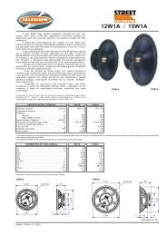
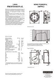
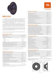
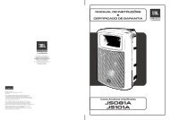
L O U D S P E A K E R SProfessional 15” woofer designed to meet a variety of PAneeds for small and medium-sized rooms, with excellentperformance in the mid and low frequency ranges.For sound reinforcement in nightclubs, dancing halls,auditoriums, bands and also for studio monitors.Its great efficiency in sound reproduction is due to theexcellent combination of the different components:- The light cone manufactured with long fiber pulp togetherwith a surround of impregnated fabric give the array great stability,high yield and low distortion.- The voice coil is made of high temperature wire, wound on®Kapton former.- The epoxy painted reinforced steel frame provides thearray with high mechanical resistance.- The magnet assembly was designed with the assistance of a FiniteElement Analysis (FEA) software in order to ensure optimization.- The use of highly resistant adhesives guarantees optimalcohesion and durability of components.PROFESSIONAL LINE - Woofer<strong>15PW6</strong>/ <strong>15PW6</strong>-SLF**<strong>15PW6</strong>-SLF: Product without Selenium logo printed on thedust cap.SPECIFICATIONSNominal diameter . . . . . . . . . . . . . . . . . . . . . . . . . . . . . 380 (15)Nominal impedance. . . . . . . . . . . . . . . . . . . . . . . . . . . . . . . . . . 8Minimum impedance @ 160 Hz. . . . . . . . . . . . . . . . . . . . . . . 7.2Power handling1Musical Program . . . . . . . . . . . . . . . . . . . . . . . . . . . . 8002AES . . . . . . . . . . . . . . . . . . . . . . . . . . . . . . . . . . . . . . 400Sensitivity (2.83V@1m) averaged from 100 to 3,000 Hz . . . 97Power compression @ 0 dB (nom. power) . . . . . . . . . . . . . 2.82Power compression @ -3 dB (nom. power)/2. . . . . . . . . . . 2.21Power compression @ -10 dB (nom. power)/10 . . . . . . . . 1.42Frequency response @ -10 dB . . . . . . . . . . . . . . . . 60 to 4,000mm (in)WWdB SPLdBdBdBHz1Power handling specifications refer to normal speech and/or music program material,reproduced by an amplifier producing no more than 5% distortion. Power is calculated astrue RMS voltage squared divided by the nominal impedance of the loudspeaker.2AES Standard (60 - 600 Hz).THIELE-SMALL PARAMETERSFs . . . . . . . . . . . . . . . . . . . . . . . . . . . . . . . . . . . . . . . . . . . . . . . 37 Hz3Vas. . . . . . . . . . . . . . . . . . . . . . . . . . . . . . . . . . . . . . . . 202 (7.13) l (ft )Qts. . . . . . . . . . . . . . . . . . . . . . . . . . . . . . . . . . . . . . . . . . . . . 0.46Qes . . . . . . . . . . . . . . . . . . . . . . . . . . . . . . . . . . . . . . . . . . . 0.417Qms. . . . . . . . . . . . . . . . . . . . . . . . . . . . . . . . . . . . . . . . . . . 17.35o (half space) . . . . . . . . . . . . . . . . . . . . . . . . . . . . . . . . . . . 2.15 %2 2Sd. . . . . . . . . . . . . . . . . . . . . . . . . . . . . . . . . . . . 0.<strong>08</strong>605 (133.4) m (in )3 3Vd (Sd x Xmax) . . . . . . . . . . . . . . . . . . . . . . . . . . . 387.0 (23.61) cm (in )Xmax (max. excursion (peak) with 10% distortion) . . . 4.5 (0.18) mm (in)Xlim (max.excursion (peak) before physical damage)21.0 (0.82) mm (in)Atmospheric conditions at TS parameter measurements:Temperature. . . . . . . . . . . . . . . . . . . . . . . . . . . . . . . . . . . 25 (77) °C (°F)Atmospheric pressure . . . . . . . . . . . . . . . . . . . . . . . . . . . . 1,016 mbHumidity. . . . . . . . . . . . . . . . . . . . . . . . . . . . . . . . . . . . . . . . . . 51 %Thiele-Small parameters are measured after a 2-hour power test using half AES power .A variation of ± 15% is allowed.ADDITIONAL PARAMETERSL . . . . . . . . . . . . . . . . . . . . . . . . . . . . . . . . . . . . . . . . . . . . . 17.0Flux density . . . . . . . . . . . . . . . . . . . . . . . . . . . . . . . . . . . . . 1.00TmTVoice coil diameter . . . . . . . . . . . . . . . . . . . . . . . . . . . . . . 75 (3) mm (in)Voice coil winding length. . . . . . . . . . . . . . . . . . . . . . 23.0 (75.4) m (ft)Wire temperature coefficient of resistance ( ). . . . . 0.00368Maximum voice coil operating temperature. . . . . . . . 240 (464)1/°C°C (°F)vc (max.voice coil operating temp./max.power) . . 0.60 (1.33)Hvc (voice coil winding depth) . . . . . . . . . . . . . . . . . . . 17 (0.67)°C/W(°F/W)mm (in)Hag (air gap height). . . . . . . . . . . . . . . . . . . . . . . . . . . 8.0 (0.32) mm (in)Re . . . . . . . . . . . . . . . . . . . . . . . . . . . . . . . . . . . . . . . . . . . . . . 6.4Mms. . . . . . . . . . . . . . . . . . . . . . . . . . . . . . . . . . . . . . . 83 (0.182)g (lb)Cms. . . . . . . . . . . . . . . . . . . . . . . . . . . . . . . . . . . . . . . . . . . 220.0 m/NRms. . . . . . . . . . . . . . . . . . . . . . . . . . . . . . . . . . . . . . . . . . . . 1.12 kg/sNON-LINEAR PARAMETERSLe @ Fs (voice coil inductance @ Fs) . . . . . . . . . . . . . . . 3.193Le @ 1 kHz (voice coil inductance @ 1kHz). . . . . . . . . . . 1.577Le @ 20 kHz (voice coil inductance @ 20 kHz) . . . . . . . . 0.816Red @ Fs . . . . . . . . . . . . . . . . . . . . . . . . . . . . . . . . . . . . . . . 0.25Red @ 1 kHz. . . . . . . . . . . . . . . . . . . . . . . . . . . . . . . . . . . . . 4.45Red @ 20 kHz . . . . . . . . . . . . . . . . . . . . . . . . . . . . . . . . . . 66.02Krm . . . . . . . . . . . . . . . . . . . . . . . . . . . . . . . . . . . . . . . . . . . . . 2.6Kxm. . . . . . . . . . . . . . . . . . . . . . . . . . . . . . . . . . . . . . . . . . . 12.80Erm . . . . . . . . . . . . . . . . . . . . . . . . . . . . . . . . . . . . . . . . . . . . 0.84Exm . . . . . . . . . . . . . . . . . . . . . . . . . . . . . . . . . . . . . . . . . . . . 0.76mHmHmHmmHADDITIONAL INFORMATIONMagnet material. . . . . . . . . . . . . . . . . . . . . . . . . . . . . . . . . . . . . . . . Barium ferriteMagnet weight . . . . . . . . . . . . . . . . . . . . . . . . . . . . . . 2,490 (87.8) g (oz)Magnet diameter x depth . . . . . . . . . . . . . . 200 x 19 (7.87 x 0.75) mm (in)Magnetic assembly weight . . . . . . . . . . . . . . . . . . . 6,360 (14.02) g (lb)Frame material. . . . . . . . . . . . . . . . . . . . . . . . . . . . . . . . . . . . . . . . . . . . . . . . SteelFrame finish . . . . . . . . . . . . . . . . . . . . . . . . . . . . . . . . . . . . . . . . . . . . Black epoxyMagnetic assembly steel finish . . . . . . . . . . . . . . . . . . . . . . . . . . . . . . Zinc-platedVoice coil material . . . . . . . . . . . . . . . . . . . . . . . . . . . . . . . . . . . . . . . . . . . Copper®Voice coil former material . . . . . . . . . . . . . . . . . . . . . . . . . . . Polyimide (Kapton )Cone material . . . . . . . . . . . . . . . . . . . . . . . . . . . . . . . . . . . . . . . . Long fiber pulp3Volume displaced by woofer . . . . . . . . . . . . . . . . . . . . 4.3 (0.152) l (ft )Net weight. . . . . . . . . . . . . . . . . . . . . . . . . . . . . . . . . 7,240 (15.96) g (lb)Gross weight . . . . . . . . . . . . . . . . . . . . . . . . . . . . . . 8,220 (18.12) g (lb)Carton dimensions (W x D x H) . . . . . . 40 x 40 x 20 (15.8 x 15.8 x 7.9) cm (in)MOUNTING INFORMATIONNumber of bolt-holes . . . . . . . . . . . . . . . . . . . . . . . . . . . . . . . . . . 8Bolt-hole diameter . . . . . . . . . . . . . . . . . . . . . . . . . . . . . 5.5 (0.22) mm (in)Bolt-circle diameter . . . . . . . . . . . . . . . . . . . . . . . . . . . 367 (14.45) mm (in)Baffle cutout diameter (front mount) . . . . . . . . . . . . . 352 (13.86) mm (in)Baffle cutout diameter (rear mount) . . . . . . . . . . . . . . 348 (13.70) mm (in)Connectors . . . . . . . . . . . . . . . . . . . . . . . . . . . . . . . . . . . . . . . . Push on terminalsPolarity . . . . . . . . . . . . . . . . . . . . . . . . . . Positive voltage applied to the positive(+) terminal gives forward cone motionMinimum clearance between the back of the magnetic assembly and theenclosure wall . . . . . . . . . . . . . . . . . . . . . . . . . . . . . . . . . . . . 75 (3) mm (in)ø 381ø 368(8x) 5.5x8ø 350ø 20016450 103 11Dimensions in mm.
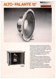
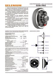
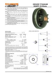
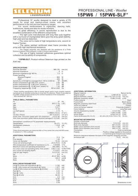
L O U D S P E A K E R SRESPONSE CURVES (0°AND 45°) IN A TEST ENCLOSURE INSIDE ANANECHOIC CHAMBER, 1 W / 1 m110100PROFESSIONAL LINE - Woofer<strong>15PW6</strong>POLAR RESPONSE CURVES60°30°50 Hz0-6-10330°300°/ <strong>15PW6</strong>-SLF*60°30°100 Hz0-6-10250 Hz-20-20-2090° dB270° 90° dB270° 90° dB270°330°300°60°30°0-6-10330°300°90120°240°120°240°120°240°dB80150°180°210°150°180°210°150°180°210°7030°500 Hz0-6330°30°800 Hz0-6330°30°1,25 kHz0-6330°60°-10300°60°-10300°60°-10300°6020 200Hz2k 20kResponse Curve at 0°.KBResponse Curve at 45°.-2090° dB 270° 90°120°150°180°210°240°120°150°-20dB180°210°270°240°-2090° dB270°120°240°150°180°210°IMPEDANCE AND PHASE CURVES MEASURED IN FREE-AIR4009030°2 kHz 3,15 kHz0-6330°30°0-6330°30°4 kHz0-6330°60°-10300°60°-10300°60°-10300°30045-2090° dB270°-2090° dB270°-2090° dB270°ohms2000degrees graus120°150°180°210°240°120°150°180°210°240°120°150°180°210°240°Polar Response Curve.100-45HARMONIC DISTORTION CURVES MEASURED AT 10% AES INPUTPOWER, 1 mdB0-9020 200 2k 20kHzBKImpedance Curve.Phase Curve.14012010<strong>08</strong>0HOW TO CHOOSE THE RIGHT AMPLIFIERThe power amplifier must be able to supply twice the RMS driver power. This3 dB headroom is necessary to handle the peaks that are common tomusical programs. When the amplifier clips those peaks, high distortionarises and this may damage the transducer due to excessive heat. The useof compressors is a good practice to reduce music dynamics to safe levels.FINDING VOICE COIL TEMPERATUREIt is very important to avoid maximum voice coil temperature. Since movingcoil resistance (RE) varies with temperature according to a well known law,we can calculate the temperature inside the voice coil by measuring thevoice coil DC resistance:TA, TB= voice coil temperatures in °C.RA, RB= voice coil resistances at temperatures TA and TB, respectively.= voice coil wire temperature coefficient at 25 °C. TB TA R RBA 1T1 25 POWER COMPRESSIONVoice coil resistance rises with temperature, which leads to efficiencyreduction. Therefore, if after doubling the applied electric power to the driverwe get a 2 dB rise in SPL instead of the expected 3 dB, we can say thatpower compression equals 1 dB. An efficient cooling system to dissipatevoice coil heat is very important to reduce power compression.A25 6020200 20kHzBKResponse Curve.Distortion Curve, 2nd harmonic.Distortion Curve, 3rd harmonic.NON-LINEAR VOICE COIL PARAMETERSDue to its close coupling with the magnetic assembly, the voice coil inelectrodynamic loudspeakers is a very non-linear circuit. Using the nonlinearmodeling parameters Krm, Kxm, Erm, Exm from an empirical model,we can calculate voice coil impedance with good accuracy.SUGGESTED PROJECTSFor additional project suggestions, please access our web site.TEST ENCLOSURE110-liter volume with a duct ø 4” by 1,7” length.Specifications subject to changewithout prior notice.www.<strong>selenium</strong>loudspeakers.comCode: Rev.: - / 01 <strong>08</strong> <strong>07</strong>NA