Deep groove ball bearings, single row
Deep groove ball bearings, single row
Deep groove ball bearings, single row
- No tags were found...

You also want an ePaper? Increase the reach of your titles
YUMPU automatically turns print PDFs into web optimized ePapers that Google loves.
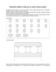
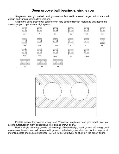
<strong>Deep</strong> <strong>groove</strong> <strong>ball</strong> <strong>bearings</strong>, <strong>single</strong> <strong>row</strong>Single <strong>row</strong> deep <strong>groove</strong> <strong>ball</strong> <strong>bearings</strong> are manufactured in a varied range, both of standarddesign and various constructive versions.Single <strong>row</strong> deep <strong>groove</strong> <strong>ball</strong> <strong>bearings</strong> can take double direction radial and axial loads andalso allow good operation at high speeds.For this reason, they can be widely used. Therefore, <strong>single</strong> <strong>row</strong> deep <strong>groove</strong> <strong>ball</strong> <strong>bearings</strong>are manufactured in many constructive versions as shown below.Beside <strong>single</strong> <strong>row</strong> deep <strong>groove</strong> <strong>ball</strong> <strong>bearings</strong> of basic design, <strong>bearings</strong> with UG design, with<strong>groove</strong>s on the outer and WL design, with <strong>groove</strong>s on both rings are also used for the purpose ofmounting seals or shields on <strong>bearings</strong>, 2ZR, 2RSR or 2RS type, as shown in the bellow figure.
SuffixesA- bearing with extended outer ringB- bearing with extended inner ringC2 - radial clearance smaller than normalC3 - radial clearance larger than normalFA - machined cage of steel or cast iron guided in the outer ringF2 - constructive modificationsK- bearing with tapered boreM- machined cage of brass guided on the rolling elementsMA - machined cage of brass guided on the outer ringMB - machined cage of brass guided on the inner ringN- circular <strong>groove</strong> for snap ring on the outer ringNR - circular <strong>groove</strong> on the outer ring and snap ringP0 - normal tolerance class (it is not marked)P6 - tolerance class more accurate than normalP63 - tolerance class P6 and radial clearance C3P5 - tolerance class more accurate than P6P4 - tolerance class more accurate than P5R- rib on the outer ringRS - bearing with special seal on one side, with friction on the inner ring recessRSA - bearing with special seal2RS - bearing with 2 seals, friction on the inner ring recessRSR - bearing with seal on one side, friction on the rib of the inner ring2RSR - bearing with 2 seals, friction on the rib of the inner ringS0 - bearing which can operate up to a temperature of +150°CS1 - bearing which can operate up to a temperature of +200°CSP - snap ring, diameter series 0,2,3,4SR - snap ring, dimension series 18 and 19T30 - bearing which can operate up to a temperature of +300°C, radial clearance0.20…0.25 mm; phosphate-treated surfacesTN - polyamide cageV- bearing without cageZ- bearing with shield and recess on the inner ringZ- sealed bearing2Z - bearing with 2 shields and recess on the inner ringZNRB - bearing with shield and snap ring on the same side
ZR - bearing with shield, without recess on the inner ring2ZR - bearing with 2 shields, without recess on the inner ringSealed and shielded deep <strong>groove</strong> <strong>ball</strong> <strong>bearings</strong>Two versions of sealed and shielded <strong>bearings</strong> are manufactured, namely:-<strong>bearings</strong> RS and Z type, with recess on the inner ring for sealing or shielding.-<strong>bearings</strong> RS and Z type, when shielding and sealing respectively are done directly on theoutside surface of the inner ring.In case of <strong>bearings</strong> with non-rubbing shields, there is a small interstice between the shieldand the rib of the inner ring: in case of <strong>bearings</strong> with seals, the gasoline and oil resistant elasticrubber lip rubs on the <strong>groove</strong> on the inner ring side or directly on the outside surface.Bearings sealed and shielded on both sides manufactured in series are delivered filled withlithium base grease and are used at temperatures between -30°C and +110°C, in accordance withthe specifications in chapter 8. Bearings can also be greased with special greases, relubricationnot being necessary. Washing or heating are not allowed before bearing mounting in the assembly.Bearings with shields have been designed first of all for cases when the inner rotates.When the outer ring rotates, the lubricant can flow out of the bearing at a certain speed. Insuch cases, we recommend you to consult our experts.<strong>Deep</strong> <strong>groove</strong> <strong>ball</strong> <strong>bearings</strong> with snap ring <strong>groove</strong>Single <strong>row</strong> deep <strong>groove</strong> <strong>ball</strong> <strong>bearings</strong>, with snap ring <strong>groove</strong> on the outer ring can be locatedin the housing with snap rings.Because of their simple and space saving mounting, these <strong>bearings</strong> simplify the assemblydesign. The <strong>groove</strong> for the snap rings are in accordance with ISO 464 and respectively.
<strong>Deep</strong> <strong>groove</strong> <strong>ball</strong> <strong>bearings</strong> with extended inner ring<strong>Deep</strong> <strong>groove</strong> <strong>ball</strong> <strong>bearings</strong> with spherical outer ring and extended inner ring aremanufactured with metric and inch dimensions. The spherical outer ring permits errors of alignmentup to 2,5°, on both sides. These <strong>bearings</strong> are generally used for agricultural machines. They arefastened on the shaft either with special screws without heads, FHS and FHSR types or with aneccentric clutch, FH and FHR types. These <strong>bearings</strong> are sealed on both sides and lubricated withlithium based grease of consistency 3.MisalignmentsSingle <strong>row</strong> deep <strong>groove</strong> <strong>ball</strong> <strong>bearings</strong> have limited abilities to compensate for bearing errorsof alignment. The permissible misalignment between the outer ring and the inner ring, which will
not produce inadmissible high additional loads in the bearing, depends on the bearing size,operational radial clearance, inner bearing design and also on the magnitude of loads andmoments acting upon the bearing.Because of the complex relationship of these influence factors, definite and universally, validvalues of permissible misalignment cannot be determined.Considering the above mentioned factors, under normal operation conditions thepermissible misalignments are between 2 and 10 minutes of arc, depending on the bearing seriesand load.It should be considered that misalignments of bearing rings in operation produce aconsiderably higher noise.DimensionsThe overall dimensions of <strong>single</strong> <strong>row</strong> deep <strong>groove</strong> <strong>ball</strong> <strong>bearings</strong> are in accordance with thestipulations of ISO 15 and national standard 3041 respectively.TolerancesSingle <strong>row</strong> deep <strong>groove</strong> <strong>ball</strong> <strong>bearings</strong> are generally manufactured with normal radialclearance. At request, they can also be manufactured with radial clearance different from thenormal one, according to table 1.Paired can be manufactured with axial clearance and preload are giving in table 2.Axial clearance of <strong>single</strong> <strong>row</strong> deep <strong>groove</strong> <strong>ball</strong> <strong>bearings</strong> is generally not standardized. It canbe defined as the axial displacement of a ring in relation to the located one, under an alternativeaxial load. The axial clearance depends on the value of the radial clearance, <strong>ball</strong> size and racewayradius. It can be calculated using the equation:Ja =ADwJr− J2rwhere:Ja = axial clearance, mm,A = bearing total curvature (raceways curvature, f e +f i -1), where f e(i) = R e(i) /D w ,D w = <strong>ball</strong> diameter, mm,J r = radial clearance, mm,R e(i) = raceways radius,mm.If a certain axial clearance is prescribed, this has to be measured and marked on the bearingby „A”, followed by clearance actual value.Radial clearance of <strong>single</strong> <strong>row</strong> deep <strong>groove</strong> <strong>ball</strong> <strong>bearings</strong>Table 1Borediameter C2 Normal C3 C4 C5dSimbolul grupei de jocuri pentru rulmenţi cu alezaj conicC2 Normal C3 C4over up to min. max. min. max. min. max. min. max. min. max.mm µm2,5 10 0 7 2 13 8 23 14 29 20 3710 18 0 9 3 18 11 25 18 33 25 4518 24 0 10 5 20 13 28 20 36 28 4824 30 1 11 5 20 13 28 23 41 30 5330 40 1 11 6 20 15 33 28 46 40 6440 50 1 11 6 23 18 36 30 51 45 7350 65 1 15 8 28 23 43 38 61 55 9065 80 1 15 10 30 25 51 46 71 65 105
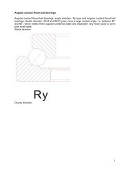
80 100 1 18 12 36 30 58 53 84 75 120100 120 2 20 15 41 36 66 61 97 90 140120 140 2 23 18 48 41 81 71 114 105 160140 160 2 23 18 53 46 91 81 130 120 180160 180 2 25 20 61 53 102 91 147 135 200180 200 2 30 25 71 63 117 107 163 150 230200 225 2 35 25 85 75 140 125 195 175 265225 250 2 40 30 95 85 160 145 225 205 300250 280 2 45 35 105 90 170 155 245 225 340280 315 2 55 40 115 100 190 175 270 245 370315 355 3 60 45 125 110 210 195 300 275 410355 400 3 70 55 145 130 240 225 340 315 460400 450 3 80 60 170 150 270 250 380 350 510450 500 3 90 70 190 170 300 280 420 390 570500 560 10 100 80 210 190 333 310 470 440 630560 630 10 110 90 230 210 360 340 520 490 690630 710 20 130 110 260 240 400 380 570 540 780710 800 20 140 120 290 270 450 430 630 600 840800 900 20 160 140 320 300 500 480 700 670 940900 1 000 20 170 150 350 330 550 530 770 740 1 0401 000 1 120 20 180 160 380 360 600 580 850 820 1 1501 120 1 250 20 190 170 410 390 650 630 920 890 1 2601 250 1 400 30 220 200 450 430 710 680 1 100 980 1 380Axial clearance and mounting preload of paired <strong>bearings</strong> series 60,62,63Tabele2Bore diameter Axial clearance Pretloadd (suffix A) (suffix L)over up to min. max. Bearing series60 62 63mm µm N- 10 15 35 30 30 -10 18 20 40 50 50 10018 30 25 45 100 100 10030 50 35 55 100 100 20050 80 40 70 200 200 35080 120 50 80 300 400 600120 180 60 100 500 700 900180 250 70 110 800 1 000 1 200Contact angleSingle <strong>row</strong> deep <strong>groove</strong> <strong>ball</strong> <strong>bearings</strong> can take over pure radial loads and also combinedloads. In this case, the <strong>ball</strong>s roll on the raceway under a contact angle α which depends on thebearing radial clearance, raceway radius and <strong>ball</strong> diameter.The contact angle can be calculated from:α =arccos⎛⎜ 1 −⎝2JrADwhere:J r = radial clearance, mm,A = bearing total curvature (raceways curvature, f e +f i -1),where f e(i) = R e(i) /D w ,D w = <strong>ball</strong> diameter, mm,w⎞⎟ ,⎠
R e(i) = raceways radius,mm.Contact angle α of ready-made <strong>bearings</strong> can be determined accurately enough with the followingequation, if the number of revolutions n i , of the inner ring, under a light axial load are considered:nc0 ⎛ D. 5 1cos ⎟ ⎞w= n⎜i−α ,⎝ Dm⎠α =arccos⎡ D⎢⎣ Dmw⎛⎜ 1 −⎝nc0 . 5 ni⎞ ⎤⎟ ⎥ ,⎠⎦where :D m = bearing mean diameter, mm,D w = <strong>ball</strong> diameter, mm.CagesSingle <strong>row</strong> deep <strong>groove</strong> <strong>ball</strong> <strong>bearings</strong> are generally fitted with cages of pressed steel sheet.Cage of glass fiber reinforced polyamide 6.6 are also suitable if the operating temperaturedoesn’t exceed +120°C. They have reduced weight, low coefficient of friction and are noiseless inoperation. Large-sized <strong>bearings</strong> are fitted with machined brass cages.Cage design and some technical data are given in table 3.Bearing minimum radial load
A minimum load must be applied on deep <strong>groove</strong> <strong>ball</strong> <strong>bearings</strong> so that they can operatecorrectly, especially in case of operating under heavy loads.The forces of inertia which occur in bearing as well as the friction in lubricant influencenegatively the operating conditions and can cause detrimental sliding movements between <strong>ball</strong>sand raceways.Minimum radial load depends on the bearing size, speed and lubricant viscosity at operatingtemperature. It can be roughly calculated from the equation:F rmin =0,01C r , (C r = basic dynamic radial load)Equivalent dynamic radial load<strong>Deep</strong> <strong>groove</strong> <strong>ball</strong> <strong>bearings</strong> can take also radial and axial combined loads.For <strong>single</strong> <strong>row</strong> deep grove <strong>ball</strong> <strong>bearings</strong>, equivalent dynamic radial load can be calculated usingthe equation:P r = F r , kN,when F a /F r ≤e,P r =XF r +Y F a , kN, when F a /F r >e.The greater the axial load, the greater the contact angle of these <strong>bearings</strong>.
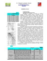
Factors e, X and Y depend on the ratio f 0* F a /C 0r . Factor f 0 can be determined using thediagram in the fallowing figure, as a function of dimension series and mean diameter (d+D)/2. F a isthe axial load and C 0r is the static basic load of the bearing.Equivalent static radial loadFor <strong>single</strong> <strong>row</strong> deep <strong>groove</strong> <strong>ball</strong> <strong>bearings</strong>, equivalent static radial load can be calculatedusing the equations:P 0 = F r , kN,when F a /F r ≤0,8,P 0 =0,6F r +0,5F a , kN, when F a /F r >0,8.The values of factors e, X, Y which depend on the bearing clearance can be determinedfrom table 4, corresponding to the values of the ratio f 0 F a /C 0r . The values in table 4, apply to<strong>bearings</strong> mounted with normal fit, i.e. shafts manufactured to tolerance class j5 or k5 and housingin j6, respectively.Calculation factors e, X for deep <strong>groove</strong> <strong>ball</strong> <strong>bearings</strong>, <strong>single</strong> mounted or matched intandemTabelul 4Normal radial clearance Radial clearance C3 Radial clearance C4f 0 F a /C 0re X Y e X Y e X Y
0,2 0,19 0,56 2,25 0,32 0,46 1,77 0,38 0,44 1,440,4 0,22 0,56 1,95 0,34 0,46 1,63 0,42 0,44 1,360,8 0,26 0,56 1,68 0,38 0,46 1,44 0,45 0,44 1,251,6 0,31 0,56 1,40 0,43 0,46 1,27 0,48 0,44 1,163 0,37 0,56 1,20 0,48 0,46 1,14 0,52 0,44 1,086 0,44 0,56 1,02 0,54 0,46 1 0,56 0,44 1Axial loadIF <strong>single</strong> <strong>row</strong> deep <strong>groove</strong> <strong>ball</strong> <strong>bearings</strong> are purely axial loaded, the axial load should not exceed0,5C 0r . In case of small-sized <strong>bearings</strong> and <strong>bearings</strong> of light series (diameter series 8, 9, 0 and 1),the axial load should not exceed 0,25C 0r .Heavy axial loads cause a significant decrease of bearing rating life. In such cause a significantdecrease of bearing rating life. In such cases, we recommend you to consult our experts.Abutment dimensionsFor a proper location of bearing rings on the shaft shoulder and housing shoulder, respectively,maximum shaft (housing) connection radius r umax ashould be less than minimum bearing mountingchamfer r smin.The shoulder should have the proper height corresponding to maximum bearing mounting chamfer.The valueof the connection radius (r u ) and support shoulder height (h u ) as functions of mountingchamfers are given in table 5 and are in accordance with national standard STAS 6603.Abutment dimensionsTable 5r s r u h umin max minBearing series618, 619, 161, 60, 64160 62, 63mm0,15 0,15 0,4 0,7 -0,20 0,20 0,7 0,9 -0,30 0,30 1 1,2 -0,60 0,60 1,6 2,1 -1 1 2,3 2,8 -1,1 1 3 3,5 4,51,5 1,5 3,5 4,5 5,52 2 4,4 5,5 6,52,1 2,1 5,1 6 73 2,5 6,2 7 84 3 7,3 8,5 105 4 9 10 126 5 11,5 13 157,5 6 14 - -