Komet Compass Catalog
Komet Compass Catalog
Komet Compass Catalog
- No tags were found...

You also want an ePaper? Increase the reach of your titles
YUMPU automatically turns print PDFs into web optimized ePapers that Google loves.
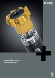
KOMET of AMERICA, Inc.KOMET de MEXICO, S. de R. L. de C.V.<strong>Compass</strong> · Internal Machining <strong>Catalog</strong>2050 Mitchell Blvd.Schaumburg, IL 60193-4544MAIN OFFICE: 847/923-8400FAX: 1-800-865-6638CUSTOMER SERVICE/ORDER ENTRY: 847/923-8480E-MAIL: customerservice@komet.comINTERNET: www.komet.comAcceso 1 No. 116 FraccionamientoIndustrial La Montaña,Querétaro, QRO. C.P 76138MEXICOTEL: (52) (442) 218-2544FAX: (52) (442) 218-2077E-MAIL: kometdemexico@komet.comCOMPASS – INTERNAL MACHINING CATALOGwww.komet.com399 02 026 03-5T-03/09 Printed in USA • © 2009 KOMET of America Inc. • We reserve the right to make modifications.
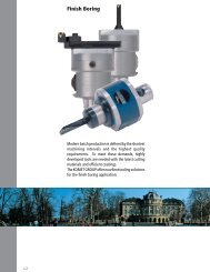
With innovative solutions and tool designs for internal machining, the KOMET GROUP holds a leading market role worldwide.Our developments for drilling, boring, tapping and reaming contribute enormously to our customers’ success.<strong>Compass</strong> – focusing on the demands of internal machiningThis new <strong>Compass</strong> catalog opens up the whole world ofKOMET internal machining for you. Over more than 700 pages, in easy to view format, you will find the complete drillingprogram, the relevant adapters and the appropriate extensive insert program, divided according to materialsand machining applications.The concise catalog is complete with technical descriptions, areas for use and machining and application examples.
IndexChapter123456AdapterDrillingRough BoringFine BoringEasy Special TM<strong>Komet</strong>ric ®1234567Inserts789Technical NotesAccessories, Assembly parts:ABS ® , HSK, KomLoc ® clamping systemNumerical Index89
Adapters – Perfecting the InterfaceWith our most comprehensiveprogram of Tool Adapters, wehave the perfect solution for yourrequirement.The Results:• Highest tool change accuracy• Perfect static rigidity• High radial rigidity• Fast tool change• Ideal dimensions• Reduced tool weight1.2
Adapters1PageAdapter Program OverviewTaper Shank HoldersFlange Adapters1.4 – 1.51.6 – 1.231.24 – 1.35HSK AdaptersABS ® AdapterClamping Units for TurningThermal Expansion System1.36 – 1.451.46 – 1.841.851.86 – 1.95Easy Special TM Adapters Chapter 51.3
Adapter Program OverviewTaper Shank HolderTaper Shank HolderTaper Shank HolderHSK AdapterCATMORI-SEIKINMTBwith ABS ® 1.8–1.9with ABS ® 1.9with ABS ® 1.11Adapter with ABS ® 1.38for Coolant Glandswith ABS ® 1.8for Coolant Glandswith ABS ® 1.17for Coolant Glandswith ABS ® 1.11Eccentric Adapterwith ABS ® 1.38Eccentric Holderwith ABS ® 1.12Precision Tool HolderFWD1.39BTDIN 69871 AD/BCoolant Inducer 1.13with ABS ®with ABS ® 1.10with ABS ® 1.12Hydraulic Chuck 1.40–1.41Integral Drill Holder 1.14for Coolant Glandswith ABS ® 1.10Collet Holder SZV 1.42Flange AdapterIntegral Micro-Adj.Boring Head1.15Eccentric Holder 1.12with ABS ®Spindle Adapter Flange1.26Tapping Chuck GWF 1.43Integral Mill DrillChuck1.16–1.17Coolant Inducerwith ABS1.13Adapter Flangewith KomLoc ® System1.28–1.31CAT - HSK Adapter 1.44Integral Precision ToolHolder1.18Integral Drill Holderwith ABS ®1.14Built-in Flangewith KomLoc ® System1.32–1.35Integral Collet Holder 1.19Integral HydraulicChuck1.20–1.231.4
Adapter Program OverviewAdapter ABS ® Tool Holder ABS ® N Clamping Unitfor Turning ToolSymbol1NC-VDI Clamping Unit 1.48–1.49Precision Tool HolderFWD1.60–1.61Straight Shank BoringBar Clamping Unit1.85Machine ConnectionExampleCATBTNMTBHSK-AISO12164-1ABS ®Clamping Unit 1.50–1.53End Mill HolderEMH / HWD1.62–1.63Balancing NoteExamplePre-balancedQ6.38,000 RPMEccentric Adj. Holder 1.54with ABS ®Morse Taper HolderHMK1.64Thermal ExpansionSystemCoolant SupplyExampleCentral/RingTC Round ShankAdapter1.55Tapping Chuck HolderGWF1.65–1.69HSK-A ThermalExpansion Chuck1.88Total RunoutExample 5 µmLightweightMicro-adjustable DrillHolder with ABS ® 1.56Collet HolderSZV1.70–1.79CAT ThermalExpansion Chuck1.89–1.90Rotating Tool / WorkpieceExampleABS ® Reducer 1.57Hydraulic Chuck 1.80–1.83BT ThermalExpansion Chuck1.91Vibration DampeningTorsion BendingABS ® Extension 1.58Short Mill Drill ChuckKMDC / NCB1.84ABS ® ThermalExpansion Chuck1.92AdjustableRadially AxiallyABS ® LightweightExtensionABS ® LightweightReducer1.591.59Easy SpecialAdapterChapter 5KomLoc ® HSK Clamping SystemExampleSystem SystemK MTool ConnectionExampleDIN1835-EWhistle NotchDIN1835-BWeldonCylindricalShankDIN6535HE+ DIN6595HSK-AISO12164-1ABS ®1.5
Taper Shank HoldersCATwith ABS ® ConnectionPage1.8 – 1.9for Coolant Glands · with ABS ® Connection1.8Eccentric Holder with ABS ® Connection1.12with ABS ® Connection / Coolant Inducer1.13Integral MV Micro-adjustable Drill Holder with ABS ® Connection1.14Integral Drill Holder with Straight Shank Connection1.14Integral Micro-Adjustable Boring Head1.15Integral Mill Drill Chuck1.16Integral Precision Tool Holder1.18Integral Collet Holder1.19Integral Hydraulic Clamping Chuck1.20 – 1.231.6
Taper Shank HoldersBTwith ABS ® ConnectionPage1.101for Coolant Glands · with ABS ® Connection1.10Eccentric Holder with ABS ®1.12with ABS ® Connection / Coolant Inducer1.13Integral MV Micro-adjustable Drill Holder with ABS ® Connection1.14MORI-SEIKIwith ABS ® Connection1.9Integral Mill Drill Chuck1.17NMTBwith ABS ® Connection1.11for Coolant Glands · with ABS ® Connection1.11DIN 69871 AD/Bwith ABS ® Connection1.121.7
CATMachineConnectionCoolant SupplyCentralRotatingToolToolConnectionMachineConnectionCoolant SupplyCentral / RingRotatingToolToolConnectionCATABS ®CATABS ®Taper Shank Holderwith ABS ® Connectionfor through spindle coolantTaper Shank Holderwith ABS ® Connectionfor use with KRD / KRSD Coolant GlandsLL1Position of tool point(single point tool)LNPTL1Position of tool point(single point tool)ABSdd1ABSdCoolant Ring(see Chapter 8)ABS ®ABS ®CAT Description Order No.ABSd L L1CAT Description Order No.CoolantABSringd d1 L L1 NPT404550ABS 25CAT40 A52 10120 25 2.362 1.612 2.00ABS 32CAT40 A52 10130 32 2.362 1.612 2.20ABS 40CAT40 A52 10140 40 2.362 1.612 2.45ABS 50CAT40 A52 10150 50 2.953 2.203 2.75ABS 50CAT40 EXT A52 10180 50 5.512 4.762ABS 63CAT40 A52 10160 63 3.543 2.793 3.50ABS 25CAT45 A52 10220 25 2.362 1.612 3.30ABS 32CAT45 A52 10230 32 2.362 1.612 3.55ABS 40CAT45 A52 10240 40 2.362 1.612 4.40ABS 50CAT45 A52 10250 50 2.362 1.612 5.10ABS 63CAT45 A52 10260 63 3.346 2.596 6.20ABS 80CAT45 A52 10270 80 3.937 3.187ABS 25CAT50 A52 10320 25 2.362 1.612 3.20ABS 32CAT50 A52 10330 32 2.362 1.612 6.20ABS 40CAT50 A52 10340 40 2.362 1.612 6.40ABS 50CAT50 A52 10350 50 2.362 1.612 7.05ABS 50CAT50 EXT A52 10400 50 6.299 5.549ABS 63CAT50 A52 10360 63 3.150 2.400 7.70ABS 80CAT50 A52 10370 80 3.937 3.187 10.00ABS 100CAT50 A52 10380 100 4.921 4.171 15.00ABS 125CAT50 A52 10390 125 5.709 4.959 23.50ABS 63CAT60 A52 10460 63 3.150 2.400 16.7060ABS 80CAT60 A52 10470 80 3.150 2.400 22.00ABS 100CAT60 A52 10480 100 3.937 3.187 31.00ABS 125CAT60 A52 10490 125 5.512 4.762 33.00Delivery:Taper shank holders supplied without retention knob.Plug screw, ABS ® Replacement parts see Chapter 8.404550ABS 40CAT40KR A52 10640 40 40 3.740 0.913 1/8 3.30ABS 50CAT40KR A52 10650 50 50 3.740 0.906 1/8 3.55ABS 63CAT40KR A52 10660 63 70 4.330 1.437 1/8 4.10ABS 40CAT45KR A52 10740 40 40 3.937 1.110 1/8 5.50ABS 50CAT45KR A52 10750 50 50 3.937 1.102 1/8 5.95ABS 63CAT45KR A52 10760 63 70 4.134 1.280 1/8 7.90ABS 40CAT50KR A52 10840 40 40 3.937 1.110 1/8 7.50ABS 50CAT50KR A52 10850 50 50 3.937 1.102 1/8 8.80ABS 63CAT50KR A52 10860 63 70 4.331 1.476 1/8 10.80ABS 80CAT50KR A52 10870 80 80 4.331 1.476 1/8 11.65ABS100CAT50KR A52 10880 100 100 5.118 2.244 3/8 15.00Delivery:Taper shank holders supplied without retention knob andcoolant ring.Plug screw, ABS ® Replacement parts see Chapter 8.1.8
CAT AD/BMachineConnectionCoolant SupplyCentral / Drive CollarRotatingToolToolConnectionMORI SEIKIMachineConnectionCoolant SupplyDrive CollarRotatingToolToolConnection1CATAD/BABS ®NMORISEIKIABS ®Taper Shank Holderwith ABS ® -NConnectionTaper Shank Holderwith ABS ® ConnectionLL1Position of tool point(single point tool)LL1Position of tool point(single point tool)ABS-NdABSdABS ® NABS ®CAT Description Order No.ABS-Nd L L1MORI SEIKIDescriptionOrder No.ABSd L L14050ABS 50N-CAT40 AD/B A52 51150 50 2.953 2.203 2.75ABS 63N-CAT40 AD/B A52 51160 63 3.543 2.793 3.50ABS 50N-CAT50 AD/B A52 51350 50 2.362 1.612 7.05ABS 63N-CAT50 AD/B A52 51360 63 3.150 2.400 7.70ABS 80N-CAT50 AD/B A52 51370 80 3.937 3.187 10.00Delivery:Taper shank holders complete without retention knob.Plug screw, ABS ® Replacement parts see Chapter 8.4050ABS 25CAT40MS A52 50120 25 2.362 1.612ABS 32CAT40MS A52 50130 32 2.362 1.612ABS 40CAT40MS A52 50140 40 2.362 1.612ABS 50CAT40MS A52 50150 50 2.953 2.203ABS 63CAT40MS A52 50160 63 3.543 2.793ABS 32CAT50MS A52 50330 32 2.362 1.612ABS 40CAT50MS A52 50340 40 2.362 1.612ABS 50CAT50MS A52 50350 50 2.362 1.612ABS 63CAT50MS A52 50360 63 3.150 2.400ABS 80CAT50MS A52 50370 80 3.937 3.187ABS 100CAT50MS A52 50380 100 4.921 4.171Delivery:Taper shank holders complete without retention knob.Plug screw, ABS ® Replacement parts see Chapter 8.1.9
NMTBMachineConnectionCoolant SupplyCentralRotatingToolToolConnectionMachineConnectionCoolant SupplyCentral / RingRotatingToolToolConnection1NMTBABS ®NMTBABS ®Taper Shank Holderwith ABS ® Connectionfor through spindle coolantTaper Shank Holderwith ABS ® Connectionfor use with KRD / KRSD Coolant GlandsLL1Position of tool point(single point tool)LNPTL1Position of tool point(single point tool)ABSdd1ABSdCoolant Ring(see Chapter 8)ABS ®ABS ®NMTBDescriptionOrder No.ABSd L L1NMTBDescriptionOrder No.CoolantABSringd d1 L L1 NPT4050ABS 40NMTB40 A71 50140 40 1.969 1.067 2.5ABS 50NMTB40 A71 50150 50 1.969 1.146 2.5ABS 63NMTB40 A71 50160 63 3.150 2.327 4.5ABS 40NMTB50 A71 50340 40 2.362 0.945 7.5ABS 50NMTB50 A71 50350 50 2.362 0.945 7.5ABS 63NMTB50 A71 50360 63 2.756 1.339 8.5ABS 80NMTB50 A71 50370 80 3.150 2.555 10.0Delivery:Taper shank holders supplied without retention knob.Plug screw, ABS ® Replacement parts see Chapter 8.50ABS 50NMTB50KR A71 50850 50 50 3.740 1.024 1/8 9.0ABS 63NMTB50KR A71 50860 63 70 4.134 1.398 1/8 10.5ABS 80NMTB50KR A71 50870 80 80 4.331 1.594 1/8 12.0Delivery:Taper shank holders supplied without retention knob andcoolant ring.Plug screw, ABS ® Replacement parts see Chapter 8.1.11
DIN 69871 AD/BCAT / BTMachineConnectionBalancing Note(Chapter 9)Coolant SupplyCentral / Drive CollarRotatingToolToolConnectionMachineConnectionCoolant SupplyDrive CollarAdjustableRotatingToolToolConnectionDIN69871AD/BPre-balancedQ6.38,000 RPMABS ®CAT /BTABS ®Taper Shank Holderwith ABS ® ConnectionEccentric-Taper Shank Holderwith ABS ® ConnectionLL1Position of tool point(single point tool)Adjustment range± 0.010“ on diameterLPosition of tool point(single point tool)ABSdABSdABS ®ABS ®ISO Description Order No.ABSd L L1CAT / BTDescriptionOrder No.ABSdL4050ISOABS 50 ISO40-AD/B A50 55150 50 1.969 1.181 2.43ABS 63 ISO40-AD/B A50 55160 63 3.543 2.756 4.52ABS 40 ISO50-AD/B A50 55340 40 2.362 0.787 7.28ABS 50 ISO50-AD/B A50 55350 50 2.362 0.866 7.28ABS 63 ISO50-AD/B A50 55360 63 2.362 1.142 7.43ABS 80 ISO50-AD/B A50 55370 80 2.756 1.969 8.62ABS 100 ISO50-AD/B A50 55380 100 4.528 3.740 12.61ABS 125 ISO50-AD/B A50 55390 125 5.709 4.921Delivery:Taper shank in version B complete with change kit, sealscrew and seal ring less retention knob.Balancing Note:Tool Holders or adapters, such as the one show above, are suppliedas a balanced unit. No allowance has been made for itemsused with the unit such as boring tools, milling cutters, inserts,and etc.When used at high speeds, we recommend a precision balancingof entire assembly prior to use.Change kitOrder No.Replacement PartsSeal screwOrder No.Seal ringOrder No.40 L02 30920 5504100810 569410081150 L02 30940 5504101215 5694101215CAT 40 ABS 50 CAT 40 AD/B EH A52 11151 50 2.953CAT 40 ABS 63 CAT 40 AD/B EH A52 11160 63 3.543CAT 50 ABS 50 CAT 50 AD/B EH A52 11351 50 2.362CAT 50 ABS 63 CAT 50 AD/B EH A52 11360 63 3.150BT 40 ABS 50 BT 40 AD/B EH A55 56150 50 2.362 2.82BT 50 ABS 50 BT 50 AD/B EH A55 56350 50 2.756 8.69Delivery:Eccentric taper shank drill holder complete without retentionknob.Note:Additional ABS ® sizes and machine connections areavailable upon request.CAT / BTAdjustment KeyOrder No.Replacement PartsChange KitOrder No.CAT 40 1804300028CAT 50 1804300028BT 40 1804300028 L02 30920BT 50 1804300028 L02 309401.12
CAT / BTMachineConnectionCoolant SupplyInducerRotatingToolToolConnection1CAT /BTABS ®Taper Shank Holderwith ABS ® ConnectionLd2Adjustable0° - 360°dd1SET LENGTH(Adjustable)ASSTOP BLOCKSTROKE.24" .09Jd3ABS ®CAT / BTDescriptionOrder No.ABSd L A d1 d2 d3 S JCAT 40 ABS 50 CI/CAT 40 A52 20550 50 5.512 0 2.551 3.86 1.38 2.56 0.590 12.50CAT 50 ABS 50 CI/CAT 50 A52 20950 50 5.512 0 2.551 3.86 1.38 3.15 0.590 17.00CAT 50 ABS 63 CI/CAT 50 A52 20960 63 5.709 0 2.551 3.86 1.38 3.15 0.787 17.10BT 40 ABS 50 CI/BT 40 A55 10550 50 5.709 0.24 2.551 3.86 1.38 2.56 0.511 12.50BT 50 ABS 50 CI/BT 50 A55 10950 50 6.102 0.59 2.551 3.86 1.38 3.15 0.551 19.30BT 50 ABS 63 CI/BT 50 A55 10960 63 6.299 0.59 2.551 3.86 1.38 3.15 0.748 19.10Delivery:Taper shank holder complete with coolant reducer, less stopblock, mounting hardware and retention knob.Note:Coolant must be filtered.For stop block dimensions and mounting information,see Chapter 8.• Improved hole making with better chip control.• Faster feeds and speeds.• Longer tool life.• Up to 5000 RPM and maximum 285 PSI coolant pressure• Enables deep hole operations.• Suitable for use with carbide drills for improvedproductivity.• Provides better control of work piece tolerance due toreduced heat.1.13
CAT / BTMachineConnectionCoolant SupplyCentralAdjustableRotatingToolToolConnectionMachineConnectionCoolant SupplyCentral / RingRotatingToolToolConnectionCAT /BTABS ®CATStraightShankIntegral Drill Holderfor ABS ® ConnectionIntegral Drill Holderfor Straight Shank ConnectionLLL1EABSdd1d*Coolant RingImportant!KUB IT HD Drills used with these holders must be cut off atnotch on shank!ABS ®CAT / BTDescriptionOrder No.ABSd d1 L ECAT Description Order No. d1 L L1CAT 40 CAT 40MV-ABS 50 M01 06030 50 2.756 3.622 0.059CAT 50 CAT 50MV-ABS 50 M01 06040 50 2.756 3.622 0.059BT 40 BT 40MV-ABS 50 M01 06110 50 2.756 3.622 0.059Delivery:Integral drill holder complete without retention knob.ABS ® Replacement parts see Chapter 8.Note:The ABS ® seal cannot be fitted into the M01 MicroAdjustable Holder50 ZWH 1.250 CAT 50 A05 00310 1.250 4.913 3.075 9.050 ZWH 1.500 CAT 50 A05 00320 1.500 4.913 3.159 10.1Delivery:Integral drill holder complete without retention knob.Note:Other shank sizes are available on request.* Please use the coolant ring KRD 60 (L0100021)on page 8.41Accurate adjustment with micro-adjustable spindle• Maximum adjustment range .125" on diameter• Scale divisions .001" on diameter• Rigid clamping of head after adjust ment achieved by means of 4clam ping screws on face1.14
CATMachineConnectionCoolant SupplyCentralAdjustableRotatingToolToolConnection1CATABS ®Integral Micro-adjustable Boring Head M020(KFK)radial adjustment of 0.0001“ (0.002mm) per graduation ondiameter, using vernier scaleLL1Ø 0.019“ - 0.079“ 4.61(Ø 0.5mm - 2.0mm)Ø 0.118“ - 0.354“ 4.61(Ø 3.0mm - 9.0mm)Ø 0.220“ - 0.472“ 4.62(Ø 5.6mm - 12.0mm)Ø 0.220“/ 0.272“ 4.70(Ø 5.6mm - 6.9mm)d2ABSd1Ø 0.354“/ 0.433“ 4.70(Ø 5.6mm - 6.9mm) 4.60Ø 0.512“ - 0.669“ 4.70(Ø 13.0mm - 17.0mm)Ø 0.315“ - 1.102“ 4.64(Ø 8.0mm - 28.0mm)Ø 0.469“ - 1.181“ 4.68(Ø 11.9mm - 30.0mm)Ø 1.102“ - 1.732“ 4.96(Ø 28.0mm - 44.0mm)Ø 1.496“ - 4.055“ 4.27(Ø 38.0mm - 103.0mm) 4.26CAT Description Order No.ABSd1d2AdjustmentLL140 CAT 40 KFK1-Z-ABS 32 M02 07200 32 2.692 0.157 3.740 0.63550 CAT 50 KFK1-Z-ABS 32 M02 07210 32 2.756 0.157 3.740 0.635Delivery:Integral micro-adjustable boring head complete withoutretention knob.ABS ® Replacement parts see Chapter 8.The micro-adjustable head balanced in zero positionBoring Range:D min= DD max= D1(2×S)1.15
CATMachineConnectionCoolant SupplyCentralRotatingToolToolConnectionCATStraightShankIntegral Mill Drill ChuckCATd1L1L(...) = mmCAT Description Order No. L d1 d2 L14050KMDC 0.5-13 CAT40 A34 60010 4.331 (110) 0.020-0.512 (0.5-13) 1.949 (49.5) 1.142 (29) 4.5KMDC 3-16 CAT40 A34 60020 4.331 (110) 0.118-0.630 (3-16) 2.047 (52) 1.142 (29) 4.7KMDC 0.5-13 CAT50 A34 60050 4.331 (110) 0.020-0.512 (0.5-13) 1.949 (49.5) 1.142 (29) 9.1KMDC 3-16 CAT50 A34 60060 4.331 (110) 0.118-0.630 (3-16) 2.047 (52) 1.142 (29) 9.2KMDC 12-20 CAT 50 A34 60070 4.567 (110) 0.472-0.787 (12-20) 2.480 (63) 1.575 (40) 10.3Delivery:Integral mill drill chuck complete with hex socket wrench,interchangeable seals and seal changing tool less retention knob.1.16
CAT MSMachineConnectionCoolant SupplyCentral / Drive CollarRotatingToolToolConnection1CATMSStraightShankIntegral Mill Drill ChuckCAT MSd1 d2L1L(...) = mmCAT MSDescription Order No. L d1 d2 L140 KMDC 3-16 CAT 40 MS A34 60080 4.331 (110) 0.118-0.630 (3-16) 2.047 (52) 1.142 (29) 4.750 KMDC 3-16 CAT 50 MS A34 60090 4.331 (110) 0.118-0.630 (3-16) 2.047 (52) 1.142 (29) 9.2Delivery:Integral mill drill chuck complete with hex socket wrench,interchangeable seals and seal changing tool less retention knob.1.17
CATMachineConnectionCoolant SupplyCentralRotatingToolToolConnectionCATStraightShankIntegral FWD Precision Tool Holderfor Straight Shank Connection(Metric)L10 d1d2L1All dimensions are in mmReplacement PartsClamping ScrewAdjusting ScrewCAT Description Order No. d1 d2 L L1Order No.Order No.4050CAT 40 FWD 10MM A25 56820 10 28 50 40 N00 70310 N00 71130CAT 40 FWD 12MM A25 56830 12 42 50 45 N00 70370 N00 71230CAT 40 FWD 14MM A25 56840 14 42 50 45 N00 70370 N00 71320CAT 40 FWD 16MM A25 56850 16 48 63 48 N00 70400 N00 71410CAT 40 FWD 18MM A25 56860 18 48 63 48 N00 70400 N00 71410CAT 40 FWD 20MM A25 56870 20 52 63 50 N00 70450 N00 71500CAT 40 FWD 25MM A25 56880 25 52 90 56 N00 70450 N00 71500CAT 50 FWD 10MM A25 66820 10 28 63 40 N00 70310 N00 71130CAT 50 FWD 12MM A25 66830 12 42 63 45 N00 70370 N00 71230CAT 50 FWD 14MM A25 66840 14 42 63 45 N00 70370 N00 71320CAT 50 FWD 16MM A25 66850 16 48 63 48 N00 70400 N00 71410CAT 50 FWD 18MM A25 66860 18 48 63 48 N00 70400 N00 71410CAT 50 FWD 20MM A25 66870 20 52 63 50 N00 70450 N00 71500CAT 50 FWD 25MM A25 66880 25 52 80 56 N00 70450 N00 71500Delivery:Integral precision tool holder complete with clamping andadjusting screws, less hex socket type wrench and retentionknob.• Total Runout 0.01 mm.• A 2° tilted clamping screw secures tool from being pulledout of the chuck.• Central coolant supply through Adjusting Screw.• Length axially adjustable.1.18
CATMachineConnectionCoolant SupplyCentralRotatingToolAdjustableToolConnection1CATCylindricalShankIntegral Collet HolderExternally Adjustable - SZVLVd1Adjusting screw*Dimension “L“ depends on clamping range of colletCAT Description Order No. d1 L* VReplacement PartsCollet nut Spanner wrench Max.collet nutclampingDescription Order No. Description Order No.torque(ft-lbs)40 CAT 40 SZV/ER 32 A05 80350 1.969 3.500 0.402 KC/ER 32 5280601032 E 32 L05 02050 12050 CAT 50 SZV/ER 32 A05 80450 1.969 3.500 0.472 KC/ER 32 5280601032 E 32 L05 02050 120Delivery:Integral collet holder complete with collet nut, shortadjusting screw with hole, less collet, spanner wrench andretention knob.Note:Please see pages 1.72 - 1.79 for the selection of collets,collet nuts and seal disks• For clamping tools with cylindrical shank up to 3/4”(20mm) diameter• Concentricity between taper and tool shank 0.0006“(0.015mm)• Axial adjustment via side adjustable rack and pinionsystem without removal of tool1.19
CATMachineConnectionCoolant SupplyCentralRotatingToolToolConnectionCATStraightShankIntegral Hydraulic Clamping Chuck(Inch)10L1d1d2LReplacement PartsAdjusting ScrewCAT Description Order No. d1 d2 L L1DescriptionOrder No.4050CAT40 .250 A25 56710 .250 1.752 2.520 1.457 FWD M6X1X16 N00 71050CAT40 .375 A25 56720 .375 1.752 2.520 1.673 FWD M10X1X18 N00 71230CAT40 .500 A25 56730 .500 1.752 2.520 1.870 FWD M10X1X18 N00 71230CAT40 .625 A25 56740 .625 1.752 2.520 2.067 FWD M10X1X18 N00 71230CAT40 .750 A25 56750 .750 1.752 2.520 2.067 FWD M10X1X18 N00 71230CAT50 .250 A25 66710 .250 2.752 3.189 1.457CAT50 .375 A25 66720 .375 2.752 3.189 1.673CAT50 .500 A25 66730 .500 2.752 3.189 1.870CAT50 .625 A25 66740 .625 2.752 3.189 1.870CAT50 .750 A25 66750 .750 2.752 3.189 2.067CAT50 1.000 A25 66760 1.000 2.752 3.189 2.402CAT50 1.250 A25 66770 1.250 2.752 3.189 2.559Delivery:Integral hydraulic clamping chuck complete with adjustingscrew, less hex socket type wrench and retention knob.• Total Runout < 0.0002”• Completely enclosed pressure system, sealed against dirtand coolant• Central coolant supply through Adjusting Screw• Length axially adjustable1.20
Reducer Bushingfor Hydraulic Clamping Chucks1L1L2d1 d d2with flange grooves for peripheral coolantReducer Bushing (Inch)Order No. d d1 d2 L1 L2L01 13400 .250L01 13410 .312L01 13420 .375L01 13430 .437L01 13440 .500L01 13450 .625.750 .980 2.00 0.78Gauge PinCylindrical BrushOrder No.d1Order No.d1L00 00080 6L00 00090 8L00 00100 10L00 00110 12L00 00130 16L00 00070 20L00 00160 324779116206 64779116208 84779116210 104779116212 124779116216 164779116220 204779116232 321.21
CATMachineConnectionCoolant SupplyCentralRotatingToolToolConnectionCATStraightShankIntegral Hydraulic Clamping Chuck(Metric)10L1d1d2LAll dimensions are in mmReplacement PartsAdjusting ScrewCAT Description Order No. d1 d2 L L1DescriptionOrder No.4050CAT40 10 mm A25 56620 10 44.5 64 42.5 FWD M6X1X16 N00 71050CAT40 12 mm A25 56630 12 44.5 64 47.5 FWD M10X1X18 N00 71230CAT40 14 mm A25 56640 14 44.5 64 47.5 FWD M10X1X18 N00 71230CAT40 16 mm A25 56650 16 44.5 64 52.0 FWD M10X1X18 N00 71230CAT40 20 mm A25 56670 20 44.5 64 52.5 FWD M10X1X18 N00 71230CAT50 10 mm A25 66620 10 69.9 64 42.5CAT50 12 mm A25 66630 12 69.9 64 47.5CAT50 14 mm A25 66640 14 69.9 64 47.5CAT50 16 mm A25 66650 16 69.9 64 52.5CAT50 20 mm A25 66670 20 69.9 64 52.5CAT50 25 mm A25 66680 25 69.9 64 61.0CAT50 32 mm A25 66690 32 69.9 64 65.0Delivery:Integral hydraulic clamping chuck complete with adjustingscrew, less hex socket type wrench and retention knob.• Total Runout 0.005 mm• Completely enclosed pressure system, sealed against dirtand coolant• Central coolant supply through Adjusting Screw• Length axially adjustable1.22
Reducer Bushingfor Hydraulic Clamping Chucks1L1L2d1 d d2with flange grooves for peripheral coolantReducer Bushing (Metric)All dimensions are in mmOrder No. d d1 d2 L1 L2L01 13290 3L01 13300 4L01 13310 5L01 13320 6L01 13330 8L01 13260 3L01 13270 4L01 13280 5L01 13200 6L01 13210 8L01 13220 10L01 13230 12L01 13240 14L01 13250 16L01 13500 6L01 13510 8L01 13520 10L01 13530 12L01 13540 14L01 13550 16L01 13560 18L01 13570 20L01 13580 2512 19 45 2 0.2220 29 50.5 2 0.2232 39 60.5 3 0.66Gauge PinCylindrical BrushOrder No.d1Order No.d1L00 00080 6L00 00090 8L00 00100 10L00 00110 12L00 00130 16L00 00070 20L00 00160 324779116206 64779116208 84779116210 104779116212 124779116216 164779116220 204779116232 321.23
1.24
Flange AdaptersSpindle Adapter FlangeABS ® VFS · with ABS ® ConnectionPage1.261HSK Adapter Flange with KomLoc ® Clamping SystemAdapter FlangeHSK-RVFHSK-RVFW, Adjustable1.28 – 1.31Built-in FlangeHSK-REFHSK-REFW, Adjustable1.32– 1.35KomLoc ® HSK-Clamping SystemDetail information for KomLoc ® HSK-Clamping System is available on Chapter 8.1.25
Spindle Flange AdapterMachineConnectionCoolant SupplyCentralRotatingToolToolConnectionSpindleDIN2079ABS ®with ABS ® ConnectionThis adapter flange does not have key slots.Drive keys on spindle head must be removedSpindle head to DIN 2079d2ABSdd1d3L1LISO Description Order No.ABSd d1 d2 d3 L L1304050ABS32 VFS30 A01 01130 320.945 2.51ABS40 VFS30 A01 01140 40 1.102 2.732.756 2.749 3.5430.433ABS50 VFS30 A01 01150 50 1.260 3.13ABS63 VFS30 A01 01160 63 1.575 3.77ABS40 VFS40 A01 01240 401.102 4.45ABS50 VFS40 A01 01250 50 3.150 3.499 4.331 1.260 0.472 4.74ABS63 VFS40 A01 01260 63 1.575 5.73ABS80 VFS40 A01 01270 80 3.937 3.499 4.331 1.732 0.472 6.04ABS50 VFS50 A01 01450 501.260 10.08ABS63 VFS50 A01 01460 63 1.575 11.514.724 5.062 5.9060.669ABS80 VFS50 A01 01470 80 1.732 12.46ABS100 VFS50 A01 01480 100 2.205 14.38ABS125 VFS50 A01 01490 125 5.512 5.062 6.299 2.835 0.669 20.37Delivery:Spindle adapter flange complete.1.26
KomLoc ® HSK-Clamping SystemFeatures of the new system• Simple and low cost spindle contour• Minimum number of extremely sturdy components• Maximum clamping force• Specially designed for high speed machining (HSC)• Internal coolant supply• Practical ejector function1ApplicationsThere are numerous occasions that require manual clamping of hollow tapershank (HSK) tools. The new KOMET HSK clamping system is used throughouttransfer lines, machining centers, turning lathes, multi-head machines andpre-setting devices.• Direct mounting on multi-head machines and short boring spindles• Spindle mounted and location adapter flanges are available• Adapters for extension and reductionUsing the KomLoc ® HSK-Clamping SystemOperation of the KomLoc ® clamping system is quite simple by the turn ofa hexagonal key. A low draw-in moment automatically produces a sturdyand effective clamping action. In addition, an axial movement or turning ofthe locking ring prevents dirt and chips from penetrating into the clampingmechanism.HSC (High Speed Cutting) AbilityThe new KomLoc ® clamping system is predestined to be utilized at highcutting speeds due to the radial expanding effect of the clamping action. Theclamping cartridge is designed to be completely symmetrical in rotation.Coolant supplyInternal coolant supply is introduced by two coolant hoses which form acage with the ejector and the distributor. This cage is supported on floatingbearings and produces a seal for a coolant pressure of p > 30psiApplication detailsThe clamping adapter ensures a excellent transmission of the bending andtorsion moments by maintaining the correct draw-in moments and clampingforces. The direction of these moments is not affected by the position ofclamping cartridge.1.27
HSK-RVF Adapter FlangeMachineConnectionCoolant SupplyCentralRotatingToolAdjustableKomLoc ®HSK-ClampingToolConnectionToolConnectionMachineSpindleSystemKHSK-AISO12164-1HSK-CISO12164-1KomLoc ® HSK-Clamping System KRadially adjustable on the machine spindle with adjusting screwLL1L24×90°d1d2HSKdReplacement PartsAccessoriesKomLocClampingSeal ring,shiftingClamping screwDIN 912Description Order No.HSKd d1 d2 L L1 L2deviceOrder No. Order No. Description Order No.HSK-40 RVF A08 51031 40HSK-50 RVF A08 61031 50HSK-63 RVF A08 71031 63HSK-80 RVF A08 81030 80HSK-100 RVF A08 91030 1002.756(70)3.150(80)3.937(100)4.606(117)5.512(140)1.378(35)1.575(40)1.969(50)2.362(60)3.150(80)1.669(42.4)2.087(53)2.559(65)3.339(84.8)4.173(106)1.28(32.5)1.693(43.0)2.087(53.0)2.866(72.8)3.701(94)0.827(21)1.024(26)1.260(32)1.772(45)1.969(50)Delivery:Adapter flange complete with KomLoc ® clamping device and locking ring.Please order clamping screw separately.(..) = mm1.15 L07 01040 L07 01440 M6x20-12.9 55011 060202.14 L07 01050 L07 01450 M6x20-12.9 55011 060204.06 L07 01060 L07 01460 M8x25-12.9 55011 080257.98 L07 01070 L07 01470 M8x35-12.9 55011 0803515.66 L07 01080 L07 01480 M10x45-12.9 55011 10045Note:Please use the wiper to clean the taperand the contact face1.28
Connection dimensions for HSK-RVF Adapter Flange1L3Section A-Ad8L4AØ d6 × T +0.5022.5°AW145°30°1R 0.25L1L5R 0.4R z2.5Ø d4Ø d9Ø d3Ø d2 F8Ø d1d7R z6.3Ø d5±0.1W2O-RingNBR700.015 A10°AL60.0020.002NOT CONVEXAL2x 5:1Access hole formanual clamping(..) = mmforFlange Adapter d1 d2 d3 d4 d5 d6 d7 d8 d9 L1 L2 L3 L4 L5 L6 T W1 W2O-RingA08 51031A08 61031A08 71031A08 81030A08 910302.756(70)3.150(80)3.937(100)4.606(117)5.512(140)1.378(35)1.575(40)1.969(50)2.362(60)3.150(80)1.122(28.5)1.201(30.5)1.516(38.5)1.870(47.5)2.559(65)1.417(36)1.614(41)2.008(51)2.402(61)3.189(81)2.087(53)2.480(63)3.110(79)3.780(96)4.685(119).197(5).197(5).197(5).236(6).236(6)M6 M8X1 .197(5.0)M6 M8X1 .236(6.0)M8 M10X1 .315(8.0)M8 M10X1 .402(10.2)M10 M10X1 .472(12).406(10.3).406(10.3).484(12.3).484(12.3).484(12.3).488(12.4).524(13.3).634(16.1).634(16.1).634(16.1).327(8.3).327(8.3).406(10.3).406(10.3).406(10.3).276(7.0).276(7.0).315(8.0).315(8.0).315(8.0).551(14).551(14).591(15).709(18).787(20).709(18).709(18).787(20).866(22)1.024(26).138(3.5).138(3.5).138(3.5).177(4.5).177(4.5)0° 4X90° 28X30° 4X90° 30X40° 4X90° 38X50° 4X90° 47X522.5° 8X45° 65X5KOMET Drawing No. : N49 134701.29
HSK-RVFW Adapter Flange - AdjustableMachineConnectionCoolant SupplyCentralRotatingToolAdjustableAdjustableKomLoc ®HSK-ClampingToolConnectionMachineSpindleSystemKHSK-AISO12164-1KomLoc ® HSK-Clamping System KRadially adjustable on the machine spindle with adjusting screwFine adjustment in face run-out by adjusting screw in adapter flangeLL1L24×90°d1d2HSKdReplacement PartsAccessoriesKomLocClampingSeal ring,shiftingDisc ThreadedPinClamping screwDIN 912Description Order No.HSKd d1 d2 L L1 L2deviceOrder No. Order No. Order No. Order No. Description Order No.HSK-40 RVFW A08 52030 40HSK-63 RVFW A08 72030 63HSK-80 RVFW A08 82030 802.756 1.378 1.669 1.28 0.8271.15 L07 01040(70) (35) (42.4) (32.5) (21)L07 01440 L02 30960 N00 70250 M6x20-12.9 55011060203.937 1.969 2.559 2.087 1.2604.06 L07 01060(100) (50) (65) (53.0) (32)L07 01460 L02 30960 N00 70320 M8x25-12.9 55011080254.606 2.362 3.339 2.866 1.7727.98 L07 01070(117) (60) (84.8) (72.8) (45)L07 01470 L02 30960 N00 70330 M8x35-12.9 5501108035Delivery:Adapter flange complete with KomLoc ® clamping device, locking ring, discand threaded pin. Please order clamping screw separately.(..) = mmNote:Please use the wiper to clean the taperand the contact face1.30
Connection dimensions for HSK-RVFW Adapter Flange1L3Section A-Ad8L4AØ d6 × T +0.5022.5°AW145°30°1R 0.25L1L5R 0.4R z2.5Ø d4Ø d910°Ø d3Ø d2 F8R z6.3Ø d5±0.1Ø d1d7W2O-RingNBR700.015 AAL60.0020.002NOT CONVEXAL2x 5:1Access hole formanual clamping(..) = mmforFlange Adapter d1 d2 d3 d4 d5 d6 d7 d8 d9 L1 L2 L3 L4 L5 L6 T W1 W2O-RingA08 520302.756 1.378 1.122 1.417(70) (35) (28.5) (36)A08 720303.937 1.969 1.516 2.008(100) (50) (38.5) (51)A08 820304.606 2.362 1.870 2.402(117) (60) (47.5) (61)KOMET Drawing No. : N49 134702.087(53)3.110(79)3.780(96).197(5).197(5).236(6)M6 M8X1 .197(5.0)M8 M10X1 .315(8.0)M8 M10X1 .402(10.2).406(10.3).484(12.3).484(12.3).488(12.4).634(16.1).634(16.1).327(8.3).406(10.3).406(10.3).276(7.0).315(8.0).315(8.0).630(16).591(15).709(18).787(20).787(20).866(22).138(3.5).138(3.5).177(4.5)0° 4X90° 28X30° 4X90° 38X50° 4X90° 47X51.31
HSK-REF Built-in FlangeMachineConnectionCoolant SupplyCentralRotatingToolAdjustableKomLoc ®HSK-ClampingToolConnectionShort SpindleDIN69002SystemKHSK-AISO12164-1KomLoc ® HSK-Clamping System KRadially adjustable on the machine spindle with adjusting screwL1d1dd2(..) = mmReplacement PartsAccessoriesKomLocClampingSeal ring,turningBall pressurescrewClamping screwDIN 912Description Order No.HSKd d1 d2 L1deviceOrder No. Order No. Order No. Description Order No.HSK-50 REF A08 61060 50HSK-63 REF A08 71060 63HSK-80 REF A08 81060 80HSK-100 REF A08 91060 1001.654(42)2.165(55)2.677(68)3.465(88)2.724(69.2)3.465(88)4.331(110)5.394(137).689(17.5).886(22.5)1.083(27.5)1.181(30)Delivery:Built-in flange complete with KomLoc ® clamping device and locking ring.Please order clamping screw separately1.19 L07 01050 L07 01761 N10 30739 M5x20-12.9 55011050202.47 L07 01060 L07 01771 N10 30740 M6x30-12.9 55011060304.83 L07 01070 L07 01780 N10 30741 M8x35-12.9 55011080359.04 L07 01080 L07 01790 N10 30742 M10x1x40-12.9 5501110042Note:Please use the wiper to clean the taperand the contact face1.32
Connection dimensions for HSK-REF Built-in Flange1Ø d3+0.1+0.05Ø d4Ø d5d7R z2.5Section A-AL9 +0.30L1 +0.30d8L70.002NOT CONVEX0.03 AAAAOptional with Helicoilthreaded insertR30°6×60°R z6.3120°L5×30°Ø d2 +0.15+0.1Ø d6±0.1Ø d1L10R z6.345°L8A4×90°L4L6×15°L2±0.04L3 +1 0Position of access hole forclamping system(..) = mmforBuilt-in Adapter d1 d2 d3 +0.5 d4 d5 d6 d7 d8 L1 L2 L3 L4 L5 L6 L7 L8 L9 L10 RA08 610602.480 1.654 1.299 1.024(63) (42) (33) (26)A08 710603.150 2.165 1.673 1.339(80) (55) (42.5) (34)A08 810603.937 2.677 2.079 1.654(100) (68) (52.8) (42)A08 910604.921 3.465 2.598 2.087(125) (88) (66) (53)KOMET Drawing No. : N49 13460.394(10).630(16).630(16).787(20)2.047(52)M5 M52.598(66)M6 M63.228(82)M8 M84.173(106) M10X1 M8 1.354(34.4).591 .974 1.398(15) (24.75) (35.5).705 1.195 1.673(17.9) (30.35) (42.5).957 1.583 2.256(24.3) (40.2) (57.3)2.142 2.992(54.4) (76).118(3).138(3.5).157(4).177(4.5).059(1.5).059(1.5).079(2).079(2).039(1).039(1).059(1.5).079(2).197(5).236(6).315(8).315(8).472(12).630(16).709(18).984(25).724(18.4).941(23.9)1.295(32.9)1.669(42.4).610(15.5).787(20).976(24.8)1.236(31.4).098(2.5).118(3).138(3.5).177(4.5)1.33
HSK-REFW Built-in Flange - AdjustableMachineConnectionCoolant SupplyCentralRotatingToolAdjustableAdjustableKomLoc ®HSK-ClampingToolConnectionShort SpindleDIN69002SystemKHSK-AISO12164-1KomLoc ® HSK-Clamping System KRadially adjustable on the machine spindle with adjusting screwFine adjustment in face run-out by adjusting screw in adapter flangeL1d1dd2Replacement PartsAccessoriesKomLocClampingSeal ring,turningBall pressurescrewDisc ThreadedPinClampingscrewHSKdeviceDIN 912Description Order No. d d1 d2 L1 Order No. Order No. Order No. Order No. Order No. Order No.DescriptionHSK-40 REFW A08 72060 1002.165 4.331 .9453.84 L07 01060 L07 01780 N10 30741 L02 30960 N00 70270 5501108035(55) (110) (24)(M8X35-12.9)Delivery:Built-in flange complete with KomLoc ® clamping device, locking ring,disc and threaded pin. Please order clamping screw separately.(..) = mmNote:Please use the wiper to clean the taperand the contact face1.34
Connection dimensions for HSK-REFW Built-in Flange1Ø d3+0.1+0.05Ø d4Ø d5120°Ø d2 +0.15+0.1Ø d6±0.1d7Ø d1R z2.5Section A-AL9 +0.30L1 +0.30L70.002NOT CONVEX0.03 AAOptional with Helicoilthreaded insertd8AAR30°107°6×60°L5×30°L10R z6.3R z6.3d9×T45°L8A4×90°L4L6×15°L2±0.04L3 +1 0Position of access hole forclamping system(..) = mmforBuilt-in Adapter d1 d2 d3 +0.5 d4 d5 d6 d7 d8 d9 L1 L2 L3 L4 L5 L6 L7 L8 L9 L10 R TA08 720603.937(100)2.165(55)1.673(42.5)1.339(34).630(16)3.110(79)M8M60.217(5.5).650(16.5).742 1.614(28.85) (41).138(3.5).059(1.5).039(1).236(6).984(25).882(22.4).787(20).118(3).394(10)KOMET Drawing No. : N49 134601.35
HSK Adapter• The modern connection between the machine spindle and the cuttingtool is the HSK (Hollow Shank) system• The HSK is standardized per ISO 12164• The main feature of the HSK connection is the taper and face contact.• HSK provides following essential advantages:Highest tool changing accuracy, high static rigidity, highradial rigidity, compatible with high-speed machines, shortertool change times.• The version HSK-A is used with automatic tool changers with machiningcenters, turn/mill centers and other cutting tool machines.• HSK-A can also be used on machines with manual tool change.• KOMET is offering the additional HSK versions on request(see Chapter 8).1.36
HSK AdapterAdapterwith ABS ® / ABS ® N ConnectionEccentric Adapterwith ABS ® ConnectionPrecision Tool HolderHSK-A FWDPage1.381.381.391Hydraulic ChuckCollet HolderHSK-A SZVTapping ChuckHSK-A GWF1.40 – 1.411.421.43HSK with integrated KomLoc ® HSK-Clamping SystemCAT - HSK Adapter1.441.37
HSK-AMachineConnectionHSK-AISO12164-1Balancing Note(Chapter 9)Pre-balancedQ6.310,000 RPMCoolant SupplyCentralAdapterwith ABS ® ConnectionRotatingToolRotatingWorkpieceToolConnectionMachineConnectionCoolant SupplyCentralRotatingToolRotatingWorkpieceAdjustableToolConnectionHSK-AABS ® ISOABS ®12164-1LL1LL1HSKdABSd1HSKdABSd1Total adjustment± 0.0098“ (0.25 mm)on the diameter* for Fine boring application only (..) = mmABS ®ABS ®(..) = mmDescriptionOrder No.HSK ABSd d1 L L1DescriptionOrder No.HSK ABSd d1 L L1HSK-A32-ABS25 A06 00120 25 1.575 (40) 0.787 (20) 0.3532HSK-A32-ABS32 A06 00130 32 2.165 (55) 1.378 (35) 0.55HSK-A40-ABS25 A06 10120 25 1.772 (45) 0.984 (25) 0.55HSK-A40-ABS32 A06 10130 40 32 1.772 (45) 0.984 (25) 0.66HSK-A40-ABS40 A06 10140 40 2.165 (55) – 0.88HSK-A50-ABS25 A06 20121 25 1.969 (50) 0.945 (24) 0.99HSK-A50-ABS32 A06 20131 32 1.969 (50) 0.945 (24)50HSK-A50-ABS40 A06 20141 40 2.362 (60) 1.339 (34)HSK-A50-ABS50 A06 20151 50 2.756 (70) – 1.74HSK-A63-ABS25 A06 30120 25 1.969 (50) 0.945 (24) 1.54HSK-A63-ABS32 A06 30130 32 1.969 (50) 0.945 (24) 1.65HSK-A63-ABS40 A06 30140 40 2.362 (60) 1.339 (34) 2.21HSK-A63-ABS50 A06 30150 63 50 2.756 (70) 1.732 (44) 2.69HSK-A63-ABS50* A06 30220 50 1.654 (42) – 1.70HSK-A63-ABS63 A06 30160 63 3.150 (80) – 3.62HSK-A63-ABS80 A06 30170 80 3.937 (100) – 5.51HSK-A80-ABS25 A06 40120 25 2.165 (55) 1.142 (29) 2.54HSK-A80-ABS32 A06 40130 32 2.165 (55) 1.142 (29) 2.95HSK-A80-ABS40 A06 40140 40 2.559 (65) 1.535 (39) 3.0080HSK-A80-ABS50 A06 40150 50 2.953 (75) 1.929 (49) 3.53HSK-A80-ABS63 A06 40160 63 3.346 (85) 2.323 (59) 4.85HSK-A80-ABS80 A06 40170 80 3.740 (95) – 6.59HSK-A100-ABS25 A06 50120 25 2.362 (60) 1.22 (31)HSK-A100-ABS32 A06 50130 32 2.362 (60) 1.22 (31) 5.07HSK-A100-ABS40 A06 50140 40 3.150 (80) 2.008 (51) 5.40HSK-A100-ABS50 A06 50150 100 50 3.150 (80) 2.008 (51) 5.91HSK-A100-ABS63 A06 50160 63 3.150 (80) 2.008 (51) 6.64HSK-A100-ABS80 A06 50170 80 3.543 (90) 2.402 (61) 8.16HSK-A100-ABS100 A06 50180 100 3.937 (100) – 10.47HSK A 63 - ABS50 EH A06 36730 63 50 2.756 (70) 1.024 (26) 2.49HSK A 100-ABS50 EH A06 56730 100 50 3.150 (80) 1.142 (29) 5.73forHSKSizeAdjustmentKeyOrder No.Replacement PartsDelivery: Adapter fitted complete. Please order coolant supply connection and key separately .1.38Order No. Order No. Order No.63 1804300028 5139100063 1802101063 5291102926100 1804300028 5139100080 1802101080 5291103636Delivery:Eccentric adjusting holder complete.Please order coolant supply connection and key separately(see Chapter 8).
HSK-AMachineConnectionBalancing Note(Chapter 9)TotalRunoutCoolant SupplyCentralRotatingToolRotatingWorkpieceToolConnection1HSK-AISO12164-1Pre-balancedQ6.310,000 RPM 5 µmStraightShankFWD Precision Tool Holder(Metric)Short Version*Long Version10L210L2HSKdd1d2HSKdd1d2 d3LL12°2° tilted clamping screw secures toolfrom being pulled out of the chuckLL12°All dimensions are in mmReplacement PartsClamping screwAdjusting screwHSKDescriptionOrder No.d d1 d2 d3 L L1 L2Order No. Qty. Order No.HSK-A63-FWD06 A06 306006 25 80 54 36 1.81 N00 70210 1 N00 71000HSK-A63-FWD08 A06 30800 8 28 80 54 36 1.98 N00 70260 1 N00 71050HSK-A63-FWD10 A06 31000 10 35 80 54 40 2.18 N00 70310 1 N00 71120HSK-A63-FWD12 A06 31200 12 42 90 64 45 2.65 N00 70370 1 N00 71270HSK-A63-FWD14 A06 31400 14 44 90 64 45 2.65 N00 70370 1 N00 7127063HSK-A63-FWD16 A06 31600 16 48 100 74 48 3.44 N00 70400 1 N00 71420HSK-A63-FWD18 A06 31800 18 50 100 74 48 3.53 N00 70400 1 N00 71420HSK-A63-FWD20 A06 32000 20 52 100 74 50 3.68 N00 70450 1 N00 71510HSK-A63-FWD25 A06 32500 25 65 110 84 56 5.07 N00 70510 2 N00 71510HSK-A63-FWD32 A06 33200 32 72 110 84 60 5.12 N00 70550 2 N00 71510*HSK-A63-FWD06-160 A06 340606 22 33 160 134 36 N00 70200 1 N00 71000*HSK-A63-FWD08-160 A06 34080 8 24 35 160 134 36 N00 70210 1 N00 71050*HSK-A63-FWD10-160 A06 34100 10 25 39 160 134 40 N00 70210 1 N00 71120*HSK-A63-FWD12-160 A06 34120 12 26 43 160 134 45 N00 70210 1 N00 71270*HSK-A63-FWD14-160 A06 34140 14 28 44 160 134 45 N00 70260 1 N00 7127063*HSK-A63-FWD16-160 A06 34160 16 30 45 160 134 48 N00 70260 1 N00 71420*HSK-A63-FWD18-160 A06 34180 18 32 46 160 134 48 N00 70260 1 N00 71420*HSK-A63-FWD20-160 A06 34200 20 34 50 160 134 50 N00 70260 1 N00 71510*HSK-A63-FWD25-160 A06 34250 25 65 65 160 134 56 N00 70510 2 N00 71510*HSK-A63-FWD32-160 A06 34320 32 72 72 160 134 60 N00 70550 2 N00 71510Delivery:Precision tool holder complete with clamping screw andadjusting screw. Please order coolant supply connection andkey separately (see Chapter 8).1.39
HSK-AMachineConnectionBalancing Note (Chapter 9)HSK-A50 / HSK-A63Balancing Note (Chapter 9)HSK-A100TotalRunoutCoolant SupplyCentralRotatingToolToolConnectionHSK-AISO12164-1Pre-balancedQ6.315,000 RPMPre-balancedQ6.312,000 RPM 3 µmStraightShankHydraulic Chuck(Metric)LHSKdL1L2d1d2d3Closed System:The system is fully sealed. No dirt, coolant,lubricants or chips can penetrate.Maximum RPM:Dependent on the HSK size of the hydraulicchuck and can be used up to n = 50,000RPM in a fine balanced version.VL3All dimensions are in mmReplacement PartsAdjusting screwHSKDescriptionOrder No.d d1 d2 d3 L L1 L2 L3 VDescriptionOrder No.HSK-A50- D12 A06 2353012 32 40 86.5 60.5 43.5 47.5 10 M10X1X12 N00 7180050HSK-A50- D20 A06 23570 20 42 60 91.5 65.5 49.5 52.5 10 M16X1X14 N00 71550HSK-A63-D 6 A06 335006 26 50 71.5 45.5 24.5 37.5 10 1.63 M5X12 N00 71020HSK-A63-D 8 A06 33510 8 28 50 71.5 45.5 25.5 37.5 10 1.83 M6X12 N00 71070HSK-A63-D10 A06 33520 10 30 50 81.5 55.5 35.5 42.5 10 1.83 M8X1X12 N00 71730HSK-A63-D12 A06 33530 12 32 50 86.5 60.5 41.5 47.5 10 2.51 M10X1X12 N00 7180063HSK-A63-D14 A06 33540 14 34 50 86.5 60.5 41.5 47.5 10 1.83 M10X1X12 N00 71800HSK-A63-D16 A06 33550 16 38 50 91.5 65.5 48.0 52.5 10 2.32 M12X1X12 N00 71860HSK-A63-D18 A06 33560 18 40 50 91.5 65.5 48.5 52.5 10 2.01 M12X1X12 N00 71860HSK-A63-D20 A06 33570 20 42 50 91.5 65.5 49.5 52.5 10 2.54 M16X1X14 N00 71550HSK-A100-D 6 A06 535006 26 50 74.5 43.5 24.5 37.5 10 5.03 M5X12 N00 71020HSK-A100-D 8 A06 53510 8 28 50 74.5 43.5 25.5 37.5 10 5.03 M6X12 N00 71070HSK-A100-D10 A06 53520 10 30 50 88.0 59.0 35.5 42.5 10 5.29 M8X1X12 N00 71730HSK-A100-D12 A06 53530 12 32 50 93.0 64.0 41.5 47.5 10 5.05 M10X1X12 N00 71800HSK-A100-D14 A06 53540 14 34 50 93.0 64.0 41.8 47.5 10 5.40 M10X1X12 N00 71800100HSK-A100-D16 A06 53550 16 38 50 101.5 72.5 47.5 52.5 10 5.71 M12X1X12 N00 71860HSK-A100-D18 A06 53560 18 40 50 101.5 72.5 48.5 52.5 10 5.76 M12X1X12 N00 71860HSK-A100-D20 A06 53570 20 42 50 101.5 72.5 45.0 52.5 10 6.77 M16X1X14 N00 71550HSK-A100-D25 A06 53580 25 57 63 108.0 79.0 52.0 61.0 10 7.81 M16X1X14 N00 71550HSK-A100-D32 A06 53590 32 64 75 111.0 82.0 61.0 65.0 10 6.17 M16X1X14 N00 71550More HSK-sizes are available on requestCutting tool shank tolerance:h6 from 6 to 32 mm diameterDelivery:Hydraulic chuck fitted complete with adjusting screw.Please order collant supply connection and key separately (see Chapter 8).1.40
Reducer Bushingfor Hydraulic Clamping Chucks1L1L2d1 d d2with flange grooves for peripheral coolantReducer Bushing (Metric)All dimensions are in mmOrder No. d d1 d2 L1 L2L01 13290 3L01 13300 4L01 13310 5L01 13320 6L01 13330 8L01 13260 3L01 13270 4L01 13280 5L01 13200 6L01 13210 8L01 13220 10L01 13230 12L01 13240 14L01 13250 16L01 13500 6L01 13510 8L01 13520 10L01 13530 12L01 13540 14L01 13550 16L01 13560 18L01 13570 20L01 13580 2512 19 45 2 0.2220 29 50.5 2 0.2232 39 60.5 3 0.66Gauge PinCylindrical BrushOrder No.d1Order No.d1L00 00080 6L00 00090 8L00 00100 10L00 00110 12L00 00130 16L00 00070 20L00 00160 324779116206 64779116208 84779116210 104779116212 124779116216 164779116220 204779116232 321.41
HSK-A SZVMachineConnectionBalancing Note(Chapter 9)Coolant SupplyCentralRotatingToolRotatingWorkpieceToolConnectionHSK-AISO12164-1Pre-balancedQ6.310,000 RPMStraightShankCollet HolderHigh concentricity with groundthread on holder and clampingnut.Axial adjustment.L3LHSKdd1AccessoriesDescriptionOrder No.HSKd d1 L L3ClampingrangeSpannerwrenchAdjusting screwwith hole without holeOrder No. Description Order No. Order No.HSK-A50-SZV/ER16 A06 23400 28 96.4–100 26 0.5 – 10.0 1.10 L05 02020 M16×20 5104916025 N00 7045050HSK-A50-SZV/ER32 A06 23430 50 96.5–100 26 2.0 – 20.0 2.65 L05 02050 M16×20 5104916025 N00 70450HSK-A63-SZV/ER16 A06 33400 *SW25 96.4–100 26 0.5 – 10.0 2.65 – M5×8 N00 71900 N00 71910HSK-A63-SZV/ER20 A06 33410 35 96.5–100 26 1.0 – 13.0 1.92 L05 02030 M6×12 N00 71070 N00 71940HSK-A63-SZV/ER25 A06 33420 42 96.5–100 26 1.0 – 16.0 2.27 L05 02040 M8×1×14 N00 71970 N00 71980HSK-A63-SZV/ER32 A06 33430 63 50 96.5–100 26 2.0 – 20.0 3.00 L05 02050 M10×1×14 N00 71280 N00 71240HSK-A63-SZV/ER40 A06 33440 63 116.5–120 26 3.0 – 26.0 3.88 L05 02060 M12×1×18 N00 71330 N00 71340HSK-A63-SZV/ER16-160 A06 34500 *SW25 156.4–160 26 0.5 – 10.0 2.54 – M5×8 N00 71900 N00 71910HSK-A63-SZV/ER25-160 A06 34520 42 156.5–160 26 1.0 – 16.0 3.02 L05 02040 M8×1×14 N00 71970 N00 71980HSK-A100-SZV/ER16 A06 53400 *SW25 96.4–100 29 0.5 – 10.0 4.41 – M5×8 N00 71900 N00 71910HSK-A100-SZV/ER20 A06 53410 35 96.5–100 29 1.0 – 13.0 4.83 L05 02030 M6×12 N00 71070 N00 71940HSK-A100-SZV/ER25 A06 53420 42 96.5–100 29 1.0 – 16.0 5.18 L05 02040 M8×1×14 N00 71970 N00 71980HSK-A100-SZV/ER32 A06 53430 100 50 96.5–100 29 2.0 – 20.0 5.51 L05 02050 M10×1×14 N00 71280 N00 71240HSK -A100-SZV/ER40 A06 53440 63 116.5–120 29 3.0 – 26.0 6.62 L05 02060 M12×1×18 N00 71330 N00 71340HSK-A100-SZV/ER16-160 A06 54500 *SW25 156.4–160 29 0.5 – 10.0 5.29 – M5×8 N00 71900 N00 71910HSK-A100-SZV/ER25-160 A06 54520 42 156.5–160 29 1.0 – 16.0 5.87 L05 02040 M8×1×14 N00 71970 N00 71980Note: *SW25 = Wrench size 25 mmforColletsizeReplacement PartsCollet nut Collet nut for seal discAccessoriesCollet nut with bearingCollet nut with bearingfor seal discOrder No. Order No. Order No. Order No.Note:Please see pages 1.72 – 1.79 for the completeselection of collets and seal discs.The seal discs will contain coolant pressures up to2,000 PSI.ER16 5120000316 5120000416 5280703016 5280701016ER20 5120000320 5120000420 5280703020 5280701020ER25 5120000325 5120000425 5280703025 5280701025ER32 5120000332 5120000432 5280703032 5280701032ER40 5120000340 5120000440 5280703040 5280701040Delivery:Collet holder complete with collet nut.Please order separately: hook spanner, collet, adjusting screw andcoolant supply conection and key. (see Chapter 8).1.42
HSK-A GWFMachineConnectionCoolant SupplyCentralRotatingToolTool ConnectionTapping Holder1HSK-AISO12164-1ThreadTapsTapping Chuck• Quick change tapping chuck with lengthcompensation for pressure and tension.LHSKdd1d2(..) = mmDescriptionOrder No.HSKd d1 d2 LLengthcompensationfor pressure andtensionHSK-A50GWF19-IK A06 237000.748 (19) 1.535 (39) 3.76 (95.5) 15 2.2150HSK-A50GWF31-IK A06 23710 1.220 (31) 2.362 (60) 5.118 (130) 20 4.19HSK-A63GWF19-IK A06 337000.748 (19) 1.535 (39) 3.839 (97.5) 15 2.5463HSK-A63GWF31-IK A06 33710 1.220 (31) 2.362 (60) 5.118 (130) 20 4.85Delivery:Tapping chuck complete.Please order coolant supply connection and key separately(see Chapter 8).Note:Please see pages 1.66 – 1.69 for the completeselection of taping holders.1.43
MachineConnectionBalancing Note(Chapter 9)Coolant SupplyCentralRotatingToolKomLoc ®HSK-ClampingToolConnectionToolConnectionCATPre-balancedQ6.315,000 RPMSystemKHSK-AISO12164-1HSK-CISO12164-1CAT - HSK AdapterKomLoc ® HSK-Clamping System KLL2L1D1D2(..) = mmReplacement PartsDescriptionOrder No.HSKd d1 L L1 L2KomLoc ®ClampingdeviceSeal ring,shiftingOrder No. Order No. DescriptionClamping screwOrder No.HSK A/C40-CAT 50 A08 51920 40 2.750 (69.85) 6.362 (161.6) 2.362 (60) 1.378 (35) L07 01040 L07 01440 M 5X 5 5505605050HSK A/C50-CAT 50 A08 61920 50 2.750 (69.85) 6.559 (166.6) 2.559 (65) 1.378 (35) L07 01050 L07 01450 M 6X 5 5505606050HSK A/C63-CAT 50 A08 71920 63 2.750 (69.85) 6.756 (171.6) 2.756 (70) 1.378 (35) L07 01060 L07 01460 M 8X 6 5505608060HSK A/C80-CAT 50 A08 81920 80 2.750 (69.85) 7.149 (181.6) 3.150 (80) 1.378 (35) L07 01070 L07 01470 M10X 8 5505610080HSK A/C100-CAT 50 A08 91920 100 2.750 (69.85) 9.905 (251.6) 5.906 (150) 1.378 (35) L07 01080 L07 01480 M12X10 5505612100Note:Please use the wiper to clean the taperand the contact faceDelivery :Adapter complete less retention knob.Please order coolant supply connection and key separately (see Chapter 8).1.44
KomLoc ®1HSK with integratedKomLoc ® HSK-Clamping SystemFor more detailed informationsee Chapter 81.45
ABS ® / ABS ® N AdaptersNC-VDI Clamping UnitABS ® N NC · with ABS ® N ConnectionClamping Unit for Various Machine ToolsMAZAK / OKUMA / MORI-SEIKI · with ABS ® N ConnectionEccentric Adjusting Holderwith ABS ® ConnectionTC Round Shank AdapterABS ® N TC · with ABS ® N ConnectionMicro-adjustable Drill HolderABS ® MV · with ABS ® ConnectionReducerwith ABS ® / ABS ® N ConnectionExtensionwith ABS ® / ABS ® N ConnectionLightweight Extension / Reducerwith ABS ® ConnectionPage1.48 – 1.491.50 – 1.531.541.551.561.571.581.591.46
ABS ® / ABS ® N Tool HoldersPrecision Tool HolderABS ® FWDEnd Mill HolderABS ® EMH / ABS ® HWDPage1.60 – 1.611.62 – 1.631Morse Taper AdapterABS ® HMK1.64Quick-change Tapping Chuck HolderABS ® GWF1.65 – 1.69Collet HolderABS ® SZV1.70 – 1.79Hydraulic Chuck1.80 – 1.83Short Mill Drill ChuckABS ® KMDC / ABS ® NCB1.84ABS ® N Clamping Units for Turning ToolsClamping Unit for Straight Shank Boring BarsABS ® N -BA · with ABS ® N Connection1.851.47
NC-VDIMachineConnectionCoolant SupplyCentralRotatingWorkpieceToolConnectionNCVDIABS ® NClamping Unitwith ABS ® N ConnectionABS ® N -NC..10for KUB ® DrillsABS-Ndad1L1Outside insert postion onKOMET KUB ® Drills withright hand rotationLbABS ® NDescriptionOrder No.ABS-Nd L L1 a b d1ABS 50N NC3010 A01 10151 50 60 38 30 55 68 2.93ABS 50N NC4010 A01 10251 50 60 384.1640 63 83ABS 63N NC4021 A01 10261 63 70 48 5.17ABS 50N NC5021 A01 10351 50 65 356.7350 78 98ABS 63N NC5021 A01 10361 63 75 45 7.72Note:when adjusting the KUB ® drill in + X direction, use this adapter1.48
NC-VDIMachineConnectionCoolant SupplyCentralRotatingWorkpieceToolConnection1NCVDIABS ® NClamping Unitwith ABS ® N ConnectionABS ® N -NC..20for KUB ® DrillsOutside insert postion onKOMET KUB ® Drills withright hand rotationABS-Ndad1L1LbABS ® NDescriptionOrder No.ABS-Nd L L1 a b d1ABS 50N NC3020 A01 11152 50 60 38 30 55 68 2.93ABS 50N NC4020 A01 11252 50 60 384.1640 63 83ABS 63N NC4020 A01 11262 63 70 48 5.17ABS 50N NC5020 A01 11352 50 65 356.7350 78 98ABS 63N NC5020 A01 11362 63 75 45 7.72Note:when adjusting the KUB ® drill in + X direction, use this adapter1.49
MAZAKMachineConnectionCoolant SupplyNozzleRotatingWorkpieceToolConnectionMAZAKTurretABS ® NClamping Unitwith ABS ® N Connectionfor MAZAK QT15N, QT18N Machines, QualifiedefABS-NdgdcajkhibDescriptionABS ® NABS-NOrder No. d a b c d e f g h i j k lCoolantnozzle plugReplacement PartsScrewOrder No. Order No.(..) = mmABSHardwareOrder No.ABS 50N MAZAKQT15N, QT18NCLAMPING UNITABS 63N MAZAKQT15N, QT18NCLAMPING UNITA01 21350 50A01 21360 633.950 4.375 3.156 2.000 1.852 0.686(100.33)(111.12)(80.16) (50.8) (47.03) (0.750)3.950 4.375(100.33)(111.12)3.240(82.3)2.000(50.8)1.852 0.750(47.03) (19.05)60°60°0.354(9)0.354(9)1.496(38)1.496(38)2.360 0.403(59.94) (10.24)2.360 0.403(59.94) (10.24)––N00 80320 5502300612 N00 15280Note:We supply ABS ® -N clamping unit for alltypes of machine on request(Please state machine type when ordering).1.50
OKUMAMachineConnectionCoolant SupplyNozzleRotatingWorkpieceToolConnection1OKUMATurretABS NClamping Unitwith ABS ® N Connectionfor Okuma Cadet, Okuma LB15, andOkuma LB25 Machines, QualifiedeDescriptionABS ® NABS-NOrder No. d a b c d e f g h i j k lCoolantnozzle plugReplacement PartsScrewOrder No. Order No.ABSHardwareOrder No.ABS 50N OKUMACADET LB15, LB25 A01 25050 50CLAMPING UNITABS 63N OKUMACADET LB15, LB25 A01 25060 63CLAMPING UNIT3.268(83)3.268(83)4.016(102)4.016(102)2.549 1.250(64.75) (31.75)2.549 1.250(64.75) (31.75)1.575(40)1.575(40)0.591(15)0.591(15)30°30°0.531 0.787(13.49) (20)0.531 0.787(13.49) (20)2.559(65)2.559(65)0.787(20)0.787(20)0.250(6.35)0.250(6.35)® 1.51fABS-Ndgdcjklhaib(..) = mmN00 80320 5502300612 N00 15280Also fits on following machines:• Haas• DawooNote:We supply ABS ® -N clamping unit for alltypes of machine on request(Please state machine type when ordering).
MORI-SEIKIMachineConnectionCoolant SupplyNozzleRotatingWorkpieceToolConnectionMORI-SEIKITurretABS ® NClamping Unitwith ABS ® N Connectionfor Mori-Seiki SL15, ZL15 Machines, QualifiedefABS-NdgdcjklhaibDescriptionABS ® NABS-NOrder No. d a b c d e f g h i j k lCoolantnozzle plugReplacement PartsScrewOrder No. Order No.(..) = mmABSHardwareOrder No.ABS 50N MORI-SEIKISL15, ZL15CLAMPING UNITA01 24050 503.111(79.02)3.542(89.97)2.543 1.378(64.59) (35)1.262 0.375(32.05) (9.52)45°0.511 0.750 2.013(12.98) (19.07) (51.14)0.827(21)0.159N00 80320 5502300612 N00 15280(4.03)Note:We supply ABS ® -N clamping unit for alltypes of machine on request(Please state machine type when ordering).1.52
MORI-SEIKIMachineConnectionCoolant SupplyNozzleRotatingWorkpieceToolConnection1OKUMATurretABS NDescriptionABS ® NABS-NOrder No. d a b c d e f g h i j k lCoolantnozzle plugReplacement PartsScrewOrder No. Order No.ABSHardwareOrder No.ABS 50N MORI-SEIKISL20/25, ZL20/25CLAMPING UNITABS 63N MORI-SEIKISL20/25, ZL20/25CLAMPING UNITA01 24150 50A01 24160 633.543(89.99)3.543(89.99)4.132(104.95)4.132(104.95)2.905 1.575(73.78) (40)2.905 1.575(73.78) (40)1.495 0.500(37.97) (12.70)1.495 0.500(37.97) (12.70)45°45°® 1.53Clamping Unitwith ABS ® N Connectionfor Mori-Seiki SL20/25, ZL20/25 Machines, QualifiedefgABS-Nddcajklhib(..) = mm0.511 0.985 2.161 0.785 0.200(12.98) (25.02) (54.89) (19.94) (5.09)N00 80320 5502300612 N00 152800.511 0.985 2.161 0.785 0.200(12.98) (25.02) (54.89) (19.94) (5.09)Note:We supply ABS ® -N clamping unit for alltypes of machine on request(Please state machine type when ordering).
ABS ®MachineConnectionCoolant SupplyCentralAdjustableRotatingToolToolConnectionABS ®ABS ®Eccentric Adjusting Holderwith ABS ® ConnectionLABSdABSd1Total adjustment± 0.0098“ (0.25 mm)on the diameter(..) = mmAdjustment KeyDescriptionOrder No.ABSdABSd1LOrder No.ABS 50 V 50 EH A20 00620 50 50 1.969(50) 5.258 1804300028Delivery:Eccentric holder complete with adjustment key.1.54
ABS ® NMachineConnectionCoolant SupplyCentralRotatingWorkpieceToolConnection1CylindricalShankABS N® 1.55TC-Round Shank Adapterwith ABS ® N ConnectionABS ® N -TCGaGABS-NdbLABS ® NDescriptionOrder No.ABS-Nd L a b GABS 50N TC1.25-2.5 A01 17551 50 1.750 1.250 2.500 ¼NPT 2.10ABS 50N TC1.5-2.5 A01 17051 50 1.750 1.500 2.500 ¼NPT 2.38ABS 50N TC2-4 A01 17151 50 1.6884.6743.05ABS 63N TC2-4 A01 17161 63 2.000 2.000 4.559 ¼NPT 7.10ABS 80N TC2-4 A01 17171 80 2.500 4.256 8.74ABS 50N TC2.5-5 A01 17251 50 1.6885.6747.43ABS 63N TC2.5-5 A01 17261 63 2.000 2.500 5.559 ¼NPT 8.74ABS 80N TC2.5-5 A01 17271 80 2.500 5.258 10.50ABS 100N TC3-5 A01 17381 100 3.250 3.000 5.293 ¼NPT 23.16Other shank designs can be supplied on request.
ABS ®MachineConnectionCoolant SupplyCentralAdjustableRotatingToolToolConnectionABS ® ABS ®Micro-Adjustable Drill Holderwith ABS ® Connection(Inch and Metric)Ld2ABSdEABSd1ABS ® (Inch)ABS ® (Metric)All dimensions are in mmDescriptionOrder No.ABSdABSd1 d2 L EDescriptionOrder No.ABSdABSd1 d2 L EABS 50/50-MV Z M01 05000 50 50 2.756 2.244 0.059 3.55ABS 63/50-MV Z M01 05010 63 50 3.465 2.756 0.059 6.15ABS 63/63-MV Z M01 05020 63 63 3.465 2.756 0.059 6.15ABS 50/50-MV M01 00000 50 50 70 57 1.5 3.29ABS 63/50-MV M01 00010 63 50 88 70 1.5 6.62ABS 63/63-MV M01 00020 63 63 88 70 1.5 6.36• Accurate adjustment with micro-adjustable spindle• Maximum adjustment range .125" (3mm) on diameter• Scale divisions .001" (0.02mm) on diameter• Rigid clamping of head after adjustment achieved bymeans of 4 clam ping screws on face• Note: The ABS ® seal cannot be fitted into theM01 Micro adjustable holder1.56
ABS ®MachineConnectionCoolant SupplyCentralToolRotationToolConnectionABS ® N / ABS ® TMachineConnectionCoolant SupplyCentralRotatingToolToolConnection1ABS ®ABS ®ABS NABS ® NABS ®ABS ® N / ABS ® TDescriptionOrder No.ABSdABSd1 L L1DescriptionOrder No.® 1.57Reducerwith ABS ® ConnectionReducerwith ABS ® N / ABS ® T ConnectionLL1LL1ABS-NdABS-Nd1ABSdABSd1LL1ABS-TdABS-Td1ABS-N ABS-NABS-TdABS-Td1 L L1ABS 32-R 25 A20 10120 32 25 1.575 1.181 0.40ABS 40-R 32 A20 10230 40 32 1.575 1.102 0.66ABS 40-R 25 A20 10220 40 25 1.575 1.102 0.57ABS 50-R 40 A20 10340 50 40 1.969 1.378 1.37ABS 50-R 32 A20 10330 50 32 1.969 1.378 1.17ABS 50-R 25 A20 10320 50 25 1.969 1.378 1.04ABS 63-R 50 A20 10450 63 50 2.362 1.575 2.54ABS 63-R 40 A20 10440 63 40 2.362 1.575 2.32ABS 63-R 32 A20 10430 63 32 2.362 1.575 2.07ABS 63-R 25 A20 10420 63 25 2.362 1.575 1.90ABS 80-R 63 A20 10560 80 63 2.362 1.378 4.43ABS 80-R 50 A20 10550 80 50 2.362 1.378 4.08ABS 80-R 40 A20 10540 80 40 2.362 1.378 3.88ABS 80-R 32 A20 10530 80 32 2.362 1.378 3.68ABS100-R 80 A20 10670 100 80 3.150 1.969 9.06ABS100-R 63 A20 10660 100 63 3.150 1.969 8.16ABS100-R 50 A20 10650 100 50 3.150 1.969 7.39ABS125-R100 A20 10780 125 100 3.937 1.969 18.87ABS125-R 80 A20 10770 125 80 3.937 1.969 17.66ABS125-R 63 A20 10760 125 63 3.937 1.969 16.80ABS125-R 50 A20 10750 125 50 3.937 1.969 16.36ABS125-R 40 A20 10740 125 40 3.937 1.969 15.84Delivery:Reducer complete.ABS 50N-R 40 A20 20340 50 40 1.969 1.378 1.37ABS 50N-R 32 A20 20330 50 32 1.969 1.378 1.17ABS 50N-R 25 A20 20320 50 25 1.969 1.378 1.04ABS 63T-R 50 A20 21450 63 50 2.362 1.772 2.54ABS 63N-R 50 A20 20450 63 50 2.362 1.575 2.54ABS 63N-R 40 A20 20440 63 40 2.362 1.575 2.32ABS 80T-R 63 A20 21560 80 63 2.362 1.772 4.43ABS 80N-R 63 A20 20560 80 63 2.362 1.378 4.43ABS 80N-R 50 A20 20550 80 50 2.362 1.378 4.08ABS 80N-R 40 A20 20540 80 40 2.362 1.378 3.88ABS100N-R 80 A20 20670 100 80 3.150 1.969 9.06ABS100N-R 63 A20 20660 100 63 3.150 1.969 8.16ABS100N-R 50 A20 20650 100 50 3.150 1.969 7.39Delivery:Reducer complete.Other lengths available on request.Other lengths available on request.
ABS ®ABS ® N / ABS ® TMachineConnectionCoolant SupplyCentralRotatingToolToolConnectionMachineConnectionCoolant SupplyCentralRotatingToolToolConnectionABS ®ABS ®ABSABS ® NABS ® TABS ® NExtensionwith ABS ® ConnectionExtensionwith ABS ® N / ABS ® T ConnectionLLABS-NdABS-NdABSdABSdLABS-Td1ABS-NdABS ®ABS ® NDescriptionOrder No.ABSdLDescriptionOrder No.ABS-NdABS-Td1L1.58ABS25-V60 A20 00220 25 2.362 0.49ABS25-V45 A20 00020 25 1.772 0.35ABS32-V70 A20 00230 32 2.756 0.93ABS32-V50 A20 00030 32 1.969 0.64ABS32-V35 A20 00530 32 1.378 0.44ABS40-V90 A20 00240 40 3.543 1.85ABS40-V60 A20 00040 40 2.362 1.15ABS40-V40 A20 00540 40 1.575 0.79ABS50-V150 A20 00150 50 5.906 4.90ABS50-V100 A20 00250 50 3.937 3.22ABS50-V65 A20 00050 50 2.559 2.07ABS50-V50 A20 00550 50 1.969 1.57ABS63-V190 A20 00160 63 7.480 9.86ABS63-V125 A20 00260 63 4.921 6.48ABS63-V85 A20 00060 63 3.346 4.34ABS63-V60 A20 00560 63 2.362 3.02ABS80-V240 A20 00170 80 9.449 20.20ABS80-V125 A20 00270 80 4.921 10.39ABS80-V85 A20 00070 80 3.346 6.95ABS80-V70 A20 00570 80 2.756 5.69ABS100-V160 A20 00280 100 6.299 20.88ABS100-V125 A20 00080 100 4.921 16.23ABS100-V85 A20 00580 100 3.346 10.91ABS125-V200 A20 00290 125 7.874 41.81ABS125-V160 A20 00090 125 6.299 33.36Delivery:Extension complete.ABS 25N-V60 A20 056202.362 0.4925ABS 25N-V45 A20 05420 1.772 0.35ABS 32N-V70 A20 056302.756 0.93ABS 32N-V50 A20 05430 321.969 0.64ABS 32N-V35 A20 05830 1.378 0.44ABS 40N-V90 A20 056403.543 1.85ABS 40N-V60 A20 05440 402.362 1.15ABS 40N-V40 A20 05840 1.575 0.79ABS 50T-V150 A20 057505.906 4.9050 50ABS 50T-V100 A20 05651 3.937 3.22ABS 50N-V65 A20 054502.559 2.0750ABS 50N-V50 A20 05850 1.969 1.57ABS 63T-V190 A20 057607.480 9.8663 63ABS 63T-V125 A20 05661 4.921 6.48ABS 63N-V85 A20 054603.346 4.3463ABS 63N-V60 A20 05860 2.362 3.02ABS 80T-V240 A20 057709.449 20.2480 80ABS 80T-V125 A20 05671 4.921 10.39ABS 80N-V85 A20 054703.346 6.9580ABS 80N-V70 A20 05870 2.756 5.69ABS100N-V160 A20 056806.299 20.88ABS100N-V125 A20 05480 1004.921 16.23ABS100N-V85 A20 05880 3.346 10.91Delivery:Extenson complete.Note:For optimum torque drive we recommend the use of ABS ® -Textensions
ABS ® ABS ®MachineConnectionCoolant SupplyCentralLightweightRotatingToolToolConnectionMachineConnectionCoolant SupplyCentralLightweightRotatingToolToolConnection1ABS ® ABS ®ABS ®ABSdABS ®ABS ®DescriptionOrder No.ABSsizedABSsized1LDescriptionOrder No.ABSsizedABS ® 1.59Lightweight Extensionwith ABS ® ConnectionLightweight Reducerwith ABS ® ConnectionLLL1ABSdABSd1ABSd1ABSsized1 L L1ABS63-V125-LB A20 010604.921 4.1963 63ABS63-V190-LB A20 01160 7.480 5.73ABS80-V170-LB A20 010706.693 8.8280 80ABS80-V240-LB A20 01170 9.449 11.69ABS100-V200-LB A20 010807.874 16.10100 100ABS100-V300-LB A20 01180 11.811 21.39Delivery:Extension complete.ABS80-R63-LB A20 11560 80 63 5.709 4.724 6.17ABS100-R80-LB A20 11670 100 80 6.299 5.118 11.03Delivery:Reducer completeFeatures• Weight reduced up to 45%• Stable application conditions• Steel construction - i.e. hardened facesguarantees long tool life
ABS ® FWDMachineConnectionTotalRunoutCoolant SupplyCentralRotatingToolToolConnectionABS ® 10µmStraightShankPrecision Tool Holder(Metric)L2V2°A 2° tilted clamping screw secures toolfrom being pulled out of the chuck.ABSdL160°d1d2FaceClearanceX:Ø 6 = 5 mmØ 8 = 4 mmØ 10 = 5 mmØ 12 = 6 mmØ 16 = 6 mmØ 20 = 6 mmLAll dimensions are in mmReplacement PartsDescriptionOrder No.ABSd d1 d2 L L1 L2 VClamping ScrewAdjusting ScrewOrder No. Qty. Order No.ABS25 FWD6 A30 10601 25 6 25 55 – 36 10 0.21 N00 70210 1 N00 71000ABS25 FWD8 A30 10801 25 8 28 55 – 36 10 0.25 N00 70260 1 N00 71050ABS25 FWD10 A30 11001 25 10 35 60 – 40 10 0.41 N00 70310 1 N00 71100ABS32 FWD6 A30 20601 32 6 25 55 40 36 10 0.25 N00 70210 1 N00 71000ABS32 FWD8 A30 20801 32 8 28 55 40 36 10 0.29 N00 70260 1 N00 71050ABS32 FWD10 A30 21001 32 10 35 60 – 40 10 0.43 N00 70310 1 N00 71110ABS32 FWD12 A30 21201 32 12 42 65 – 45 10 0.65 N00 70370 1 N00 71210ABS40 FWD6 A30 30601 40 6 25 55 35 36 10 0.34 N00 70210 1 N00 71000ABS40 FWD8 A30 30801 40 8 28 55 35 36 10 0.38 N00 70260 1 N00 71050ABS40 FWD10 A30 31001 40 10 35 60 45 40 10 0.48 N00 70310 1 N00 71120ABS40 FWD12 A30 31201 40 12 42 65 – 45 10 0.68 N00 70370 1 N00 71220ABS40 FWD16 A30 31601 40 16 48 70 – 48 10 0.91 N00 70400 1 N00 71400ABS50 FWD6 A30 40601 50 6 25 55 30 36 10 0.53 N00 70210 1 N00 71000ABS50 FWD8 A30 40801 50 8 28 55 30 36 10 0.57 N00 70260 1 N00 71050ABS50 FWD10 A30 41001 50 10 35 60 40 40 10 0.66 N00 70310 1 N00 71130ABS50 FWD12 A30 41201 50 12 42 65 50 45 10 0.81 N00 70370 1 N00 71230ABS50 FWD16 A30 41601 50 16 48 70 55 48 10 1.01 N00 70400 1 N00 71410ABS50 FWD20 A30 42001 50 20 52 75 – 50 10 1.20 N00 70450 1 N00 71500ABS50 FWD25 A30 42501 50 25 52 75 – 50 10 1.13 N00 70450 1 N00 71500ABS63 FWD10 A30 51001 63 10 35 60 35 40 10 0.96 N00 70310 1 N00 71130ABS63 FWD12 A30 51201 63 12 42 65 45 45 10 1.08 N00 70370 1 N00 71230ABS63 FWD16 A30 51601 63 16 48 70 48 48 10 1.27 N00 70400 1 N00 71410ABS63 FWD20 A30 52001 63 20 52 75 50 50 10 1.43 N00 70450 1 N00 71500ABS63 FWD25 A30 52501 63 25 65 80 56 56 10 2.00 N00 70510 1 N00 71500ABS80 FWD16 A30 61601 80 16 48 70 50 48 10 1.80 N00 70400 1 N00 71430ABS80 FWD20 A30 62001 80 20 52 75 52 50 10 1.98 N00 70450 1 N00 71520ABS80 FWD25 A30 62501 80 25 65 80 60 58 10 2.50 N00 70510 1 N00 71600ABS80 FWD32 A30 63201 80 32 72 90 70 60 10 3.02 N00 70550 1 N00 71650Delivery:Precision tool holder complete with ABS hardware, clamping and adjusting screws and hex socket type wrenches.1.60
ABS ® FWDMachineConnectionTotalRunoutCoolant SupplyCentralRotatingToolToolConnection1 10µmStraightShankABSdReplacement PartsDescriptionOrder No.ABS ® 1.61Precision Tool Holder(Inch)L2V2°A 2° tilted clamping screw secures toolfrom being pulled out of the chuck.LL160°d1d2FaceClearanceX:Ø .250 = .197“ Ø .750 = .236“Ø .375 = .157“ Ø .875 = .236“Ø .500 = .236“ Ø 1.000 = .236“Ø .625 = .236“ABSd d1 d2 L L1 L2 VClamping ScrewAdjusting ScrewOrder No. Qty. Order No.ABS32 FWD .250 A31 22501 32 .250 .984 2.165 1.575 1.457 .394 0.61 N00 70210 1 N00 71000ABS32 FWD .375 A31 23751 32 .375 1.102 2.165 1.575 1.457 .394 0.67 N00 70260 1 N00 71100ABS32 FWD .500 A31 25001 32 .500 1.654 2.559 – 1.811 .394 1.54 N00 70350 1 N00 71300ABS40 FWD .250 A31 32501 40 .250 .984 2.165 1.378 1.457 .394 0.81 N00 70210 1 N00 71000ABS40 FWD .375 A31 33751 40 .375 1.102 2.165 1.378 1.457 .394 1.21 N00 70260 1 N00 71100ABS40 FWD .500 A31 35001 40 .500 1.654 2.559 – 1.811 .394 1.61 N00 70350 1 N00 71130ABS40 FWD .625 A31 36251 40 .625 1.654 2.559 – 1.811 .394 1.58 N00 70350 1 N00 71130ABS50 FWD .250 A31 42501 50 .250 .984 2.165 1.181 1.457 .394 1.26 N00 70210 1 N00 71000ABS50 FWD .375 A31 43751 50 .375 1.102 2.165 1.181 1.457 .394 1.33 N00 70260 1 N00 71100ABS50 FWD .500 A31 45001 50 .500 1.654 2.559 1.968 1.811 .394 1.91 N00 70350 1 N00 71310ABS50 FWD .625 A31 46251 50 .625 1.654 2.559 1.968 1.811 .394 1.85 N00 70350 1 N00 71310ABS50 FWD .750 A31 47501 50 .750 1.890 2.756 2.165 1.929 .394 2.30 N00 70400 1 N00 71410ABS50 FWD .875 A31 48751 50 .875 2.047 2.953 – 2.008 .394 2.80 N00 70450 1 N00 71500ABS50 FWD1.000 A31 40001 50 1.000 2.047 2.953 – 2.008 .394 2.66 N00 70450 1 N00 71500Delivery:Precision tool holder complete with ABS hardware, clamping and adjusting screws and hex socket type wrenches.
ABS ® EMHMachineConnectionTotalRunoutCoolant SupplyCentralRotatingToolToolConnectionABS ®10µmStraightShankEnd Mill Holder(Inch)Ldd1d2L1Replacement PartsClamping Screw Hex Socket WrenchABSDescriptionOrder No.d d1 d2 L L1DescriptionDescriptionABS 50-EMH .375 A32 41010 50 .375 1.125 2.000 1.812 1.18 3/8" - 16 3/16"ABS 50-EMH .500 A32 41020 50 .500 1.125 2.000 1.900 1.13 7/16" - 14 7/32"ABS 50-EMH .625 A32 41030 50 .625 1.969 2.625 2.188 2.35 9/16" - 12 1/4"ABS 50-EMH .750 A32 41040 50 .750 1.969 2.625 2.313 2.31 5/8" - 11 5/16"ABS 50-EMH .875 A32 41050 50 .875 1.969 2.625 2.313 2.19 5/8" - 11 5/16"ABS 63-EMH1.000 A32 51060 63 1.000 2.480 3.000 2.563 3.98 3/4" - 10 3/8"ABS 63-EHM1.250 A32 51070 63 1.250 2.480 3.000 2.563 3.68 3/4" - 10 3/8"ABS 80-EMH1.500 A32 61080 80 1.500 2.480 3.600 2.895 5.19 3/4" - 10 3/8"ABS100-EMH2.000 A32 71100 100 2.000 3.937 4.921 3.429 16.22 1" - 14 9/16"Delivery: End mill holder complete with ABS hardware,clamping screws and hex socket wrench.1.62
ABS ® HWDMachineConnectionTotalRunoutCoolant SupplyCentralRotatingToolToolConnection110µmStraightShankEnd Mill Holder(Metric)LL1ABSdd1d2L2All dimensions are in mmReplacement PartsClamping ScrewDescriptionOrder No.ABS ® 1.63ABSABS-Nd d1 d2 L L1 L2Order No.Qty.ABS50-HWD 6 A32 40010 50 6 25 45 27 40 0.51 N00 70210 1ABS50-HWD 8 A32 40020 50 8 28 45 27 40 0.49 N00 70260 1ABS50-HWD10 A32 40030 50 10 35 55 37 44 0.62 N00 70310 1ABS50-HWD12 A32 40040 50 12 42 65 50 49 0.81 N00 70370 1ABS50-HWD14 A32 40080 50 14 44 65 50 49 0.85 N00 70370 1ABS50-HWD16 A32 40050 50 16 48 65 50 52 0.94 N00 70400 1ABS50-HWD18 A32 40090 50 18 50 65 65 52 0.98 N00 70400 1ABS50-HWD20 A32 40060 50 20 52 65 65 54 1.03 N00 70450 1ABS50-HWD25 A32 40070 50 25 65 75 75 60 1.7 N00 70510 2ABS63-HWD10 A32 50030 63 10 35 55 37 44 0.88 N00 70310 1ABS63-HWD12 A32 50040 63 12 42 65 50 49 1.02 N00 70370 1ABS63-HWD14 A32 50100 63 14 44 65 50 49 1.06 N00 70370 1ABS63-HWD16 A32 50050 63 16 48 65 50 52 1.15 N00 70400 1ABS63-HWD18 A32 50110 63 18 50 65 50 52 1.21 N00 70400 1ABS63-HWD20 A32 50060 63 20 52 65 45 54 1.26 N00 70450 1ABS63-HWD25 A32 50070 63 25 65 75 75 60 1.86 N00 70510 2ABS63-HWD32 A32 50080 63 32 72 80 80 64 2.25 N00 70550 2ABS80-HWD16 A32 60050 80 16 48 65 45 52 1.51 N00 70400 1ABS80-HWD18 A32 60110 80 18 50 65 45 52 N00 70400 1ABS80-HWD20 A32 60060 80 20 52 65 45 54 1.84 N00 70450 1ABS80-HWD25 A32 60070 80 25 65 75 55 60 2.41 N00 70510 2ABS80-HWD32 A32 60080 80 32 72 80 66 64 2.62 N00 70550 2Delivery: End mill holder complete with ABS hardware,clamping screws and hex socket wrench.
ABS ® HMKMachineConnectionABS ®RotatingToolToolConnectionMorseTaperMorse Taper AdapterHolders with central coolant supply are available uponrequestLL1ABSdd1ABS ®DescriptionOrder No.ABSdd1TaperSizeDIN228 L L1ABS 50-HMK1 A34 14020 50 0.787 MK 1 3.543 3.071 0.99ABS 50-HMK2 A34 14030 50 1.181 MK 2 4.134 3.661 1.52ABS 50-HMK3 A34 14040 50 1.417 MK 3 4.921 4.449 2.11ABS 63-HMK4 A34 15050 63 1.890 MK 4 5.906 5.315 4.09Delivery:Adapter complete1.64
ABS ® GWFMachineConnectionCoolant SupplyCentralRotatingToolTool ConnectionTapping HolderMachineConnectionRotatingToolTool ConnectionTapping Holder1Max. 725 PSIThreadTapsThreadTapsABSdABS ®ABS ®DescriptionOrder No.ABSd d1 d2 LLengthcompens.for pressureand tensionDescriptionOrder No.ABSd d1 d2 LLengthcompens.for pressureand tensionABS ® ABS ® 1.65Quick-change Tapping Chuck Holderwith Coolant SupplyQuick-change Tapping Chuck Holderwithout Coolant Supply• Quick change tapping chuck with lengthcompensation for pressure and tension.LLd1d2ABSdd1d2ABS 32-GWF19-IC A34 32060 32 0.748 1.535 2.717 0.295 1.01ABS 40-GWF19-IC A34 33060 40 0.748 1.535 2.874 0.295 1.21ABS 50-GWF19-IC A34 34060 50 0.748 1.535 2.835 0.295 1.50ABS 50-GWF31-IC A34 34070 50 1.220 2.362 3.858 0.394 3.30ABS 63-GWF31-IC A34 35070 63 1.220 2.362 4.370 0.394 3.63ABS 63-GWF48-IC A34 35080 63 1.890 3.386 6.299 0.689 10.34Delivery:Quick change tapping chuck complete with ABS hardware,less tapping holders.ABS 50-GWF19 A34 34020 50 0.748 1.417 2.756 1.614 1.45ABS 50-GWF31 A34 34030 50 1.220 2.087 4.016 3.189 2.75Delivery:Quick change tapping chuck complete with ABS hardware,less tapping holders.WES Tap HolderThrough - Coolant TapBlind HoleWES KP Tap HolderStandard TapThrough HoleABS GWF Quick ChangeTapping Chuck A343with central coolant supplyWES Tap HolderThrough - Coolant TapBlind HoleWES KP Tap HolderStandard TapThrough Hole
Tapping Holder WES (Inch)• adjustable torque control• for use with ABS GWF quick change tapping chucks• for through tool coolant tapsLL1Tapping Holder WE (Inch)• for use with ABS GWF quick change tapping chucks• for through tool coolant tapsL1Ld1d2d3d1d2d3* For torque setting information contactthe Application Engineering DepartmentforTapsize Description Order No. d1 d2shank d3 L L1Permissable torque(ft. lbs.)forTapsize Description Order No. d1 d2shank d3 L L10 – 6 WES 1 B-6-.141 A34 810000141 .141 .1091.18 WES 1 B-8-.168 A34 810000168 .168 .130 1.710 WES 1 B-10-.194 A34 810000194 .194 .152 2.212 WES 1 B-12-.220 A34 810000220 .220 .165 2.51/4 WES 1 B-1/4-.255 A34 810000255 .255 .191 4.3.675/16 WES 1 B-5/16-.318 A34 810000318 .318 .238 4.2.7481.26 .983/8 WES 1 B-3/8-.381 A34 810000381 .381 .286 10.87/16 WES 1 B-7/16-.323 A34 810000323 .323 .242 17.01/2 WES 1 B-1/2-.367 A34 810000367 .367 .275 25.09/16 WES 1 B-9/16-.429 A34 810000429 .429 .322 29.01/8 ss WES 1 B-1/8P-.313 Pipe A34 810000313 .313 .2344.0–1/8 ls WES 1 B-1/8PLS-.438 Pipe A34 810000438 .438 .328 4.05/16 WES 2 B-5/16-.318 A34 820000318 .318 .2387.23/8 WES 2 B-3/8-.381 A34 820000381 .381 .286 10.87/16 WES 2 B-7/16-.323 A34 820000323 .323 .242 17.01/2 WES 2 B-1/2-.367 A34 820000367 .367 .275 25.09/16 WES 2 B-9/16-.429 A34 820000429 .429 .322 29.01.185/8 WES 2 B-5/8-.480 A34 820000480 .480 .360 36.011/16 WES 2 B-11/16-.542 A34 820000542 1.220 .542 .406 1.97 1.34 40.03/4 WES 2 B-3/4-.590 A34 820000590 .590 .442 53.013/16 WES 2 B-13/16-.652 A34 820000652 .652 .489 57.07/8 WES 2 B-7/8-.697 A34 820000697 .697 .523 69.01/4 p WESR2 B-1/4P-.562 Pipe A34 820000562 .562 .42111.03/8 p WESR2 B-3/8P-.700 Pipe A34 820000700 .700 .531 .83 14.01/2 p WESR2 B-1/2P-.687 Pipe A34 820000687 .687 .515 32.013/16 WES 3 B-13/16-.652 A34 830000652.652 .4897/8 WES 3 B-7/8-.697 A34 830000697 .697 .523 69.015/16 WES 3 B-15/16-.760 A34 830000760 .760 .570 76.01 WES 3 B-1-.800 A34 830000800 .800 .600 1.73 94.01 1/8 WES 3 B-1 1/8-.896 A34 830000896 1.889 .896 .672 2.83 1.77 126.01 1/4 WES 3 B-1 1/4-1.021 A34 830001021 1.021 .766 144.01 3/8 WES 3 B-1 3/8-1.108 A34 830001108 1.108 .831 188.03/4 p WESR3 B-3/4P-.906 Pipe A34 830000906 .906 .679.98 42.01 p WESR3 B-1P-1.125 Pipe A34 830001125 1.125 .843 81.01.6657.00 – 6 WE 1-6-.141 A34 860500141 .141 .1098 WE 1-8-.168 A34 860600168 .168 .13010 WE 1-10-.194 A34 860700194 .194 .15212 WE 1-12-.220 A34 860800220 .220 .1651/4 WE 1-1/4-.255 A34 860900255 .255 .1915/16 WE 1-5/16-.318 A34 861000318 .318 .238.7481.181 .276 .6693/8 WE 1-3/8-.381 A34 861100381 .381 .2867/16 WE 1-7/16-.323 A34 861200323 .323 .2421/2 WE 1-1/2-.367 A34 861300367 .367 .2759/16 WE 1-9/16-.429 A34 861400429 .429 .3221/8 ss WE 1-1/8P-.313 Pipe A34 865100313 .313 .2341/8 ls WE 1-1/8PLS-.438 Pipe A34 865200438 .438 .3285/16 WE 2-5/16-.318 A34 871000318 .318 .2383/8 WE 2-3/8-.381 A34 871100381 .381 .2867/16 WE 2-7/16-.323 A34 871200323 .323 .2421/2 WE 2-1/2-.367 A34 871300367 .367 .2759/16 WE 2-9/16-.429 A34 871400429 .429 .3225/8 WE 2-5/8-.480 A34 871500480 .480 .36011/16 WE 2-11/16-.542 A34 871600542 1.220 .542 .406 1.890 .433 1.1813/4 WE 2-3/4-.590 A34 871700590 .590 .44213/16 WE 2-13/16-.652 A34 871800652 .652 .4897/8 WE 2-7/8-.697 A34 871900697 .697 .5231/4 p WER2-1/4P-.562 Pipe A34 875300562 .562 .4213/8 p WER2-3/8P-.700 Pipe A34 875400700 .700 .5311/2 p WER2-1/2P-.687 Pipe A34 875500687 .687 .51513/16 WE 3-13/16-.652 A34 881800652 .652 .4897/8 WE 3-7/8-.697 A34 881900697 .697 .52315/16 WE 3-15/16-.760 A34 882000760 .760 .5701 WE 3-1-.800 A34 882100800 .800 .6001 1/8 WE 3-1 1/8-.896 A34 882200896 .896 .6721.8892.756 .551 1.7321 1/4 WE 3-1 1/4-1.021 A34 882301021 1.021 .7663/8 p WER3-3/8P-.700 Pipe A34 885400700 .700 .5311/2 p WER3-1/2P-.687Pipe A34 885500687 .687 .5153/4 p WER3-3/4P-.906 Pipe A34 885600906 .906 .6791 p WER3-1P-1.125 Pipe A34 885701125 1.125 .843
Tapping Holder WES (Metric)• adjustable torque control• for use with ABS GWF quick change tapping chucks• for through tool coolant tapsLL1Tapping Holder WE (Metric)• for use with ABS GWF quick change tapping chucks• for through tool coolant tapsL1L1d1d2d3d1d2d3* For torque setting information contactthe Application Engineering DepartmentAll dimensions are in mmAll dimensions are in mmforTapsize Description Order No. d1 d2shank d3 L L1forTapsize Description Order No. d1 d2shank d3 L L1M 3M 4WES 1 B M3WES 1 B M4A34 911000350A34 9112004503.54.52.73.4M 5 WES 1 B M5 A34 911400600 6.0 4.9M 6 WES 1 B M6 A34 911500600 19 6.0 4.9M 8 WES 1 B M8 A34 911600600 6.0 4.9M 10 WES 1 B M10 A34 911700700 7.0 5.5M 12 WES 1 B M12 A34 911800900 9.0 7.032 25 17M 3M 4WE 1 M3WE 1 M4A34 961000350A34 9612004503.54.52.73.4M 5 WE 1 M5 A34 961400600 6.0 4.9M 6 WE 1 M6 A34 961500600 19 6.0 4.9M 8 WE 1 M8 A34 961600600 6.0 4.9M 10 WE 1 M10 A34 961700700 7.0 5.5M 12 WE 1 M12 A34 961800900 9.0 7.030 7 17M 8 WES 2 B M8 A34 921600800 8.0 6.2M 10 WES 2 B M10 A34 921701000 10.0 8.0M 12 WES 2 B M12 A34 921800900 9.0 7.0M 14 WES 2 B M14 A34 921901100 31 11.0 9.0M 16 WES 2 B M16 A34 922001200 12.0 9.0M 18 WES 2 B M18 A34 922101400 14.0 11.0M 20 WES 2 B M20 A34 922201600 16.0 12.050 34 30M 8 WE 2 M8 A34 971600800 8.0 6.2M 10 WE 2 M10 A34 971701000 10.0 8.0M 12 WE 2 M12 A34 971800900 9.0 7.0M 14 WE 2 M14 A34 971901100 31 11.0 9.0M 16 WE 2 M16 A34 972001200 12.0 9.0M 18 WE 2 M18 A34 972101400 14.0 11.0M 20 WE 2 M20 A34 972201600 16.0 12.048 11 30M 14M 16WES 3 B M14WES 3 B M16A34 931901100A34 93200120011.0 9.012.0 9.0M 18 WES 3 B M18 A34 932101400 14.0 11.0M 20 WES 3 B M20 A34 932201600 16.0 12.0M 22 WES 3 B M22 A34 932301800 48 18.0 14.5M 24 WES 3 B M24 A34 932401800 18.0 14.5M 27 WES 3 B M27 A34 932502000 20.0 16.0M 30 WES 3 B M30 A34 932602200 22.0 18.0M 33 WES 3 B M33 A34 932702500 25.0 20.072 45 44M 14M 16WE 3 M14WE 3 M16A34 981901100A34 98200120011.0 9.012.0 9.0M 18 WE 3 M18 A34 982101400 14.0 11.0M 20 WE 3 M20 A34 982201600 16.0 12.0M 22 WE 3 M22 A34 982301800 48 18.0 14.5M 24 WE 3 M24 A34 982401800 18.0 14.5M 27 WE 3 M27 A34 982502000 20.0 16.0M 30 WE 3 M30 A34 982602200 22.0 18.0M 33 WE 3 M33 A34 982702500 25.0 20.070 14 441.67
Tapping Holder WES KP (Inch)• adjustable torque control• for use with ABS GWF quick change tapping chucks• for standard tapsLL1Tapping Holder WE KP (Inch)• for use with ABS GWF quick change tapping chucks• for standard tapsL1Ld1d2d3d1d2d3* For torque setting information contactthe Application Engineering DepartmentforTapsize Description Order No. d1 d2shank d3 L L1Permissable torque(ft. lbs.)forTapsize Description Order No. d1 d2shank d3 L L10 – 6 WES 1 B KP-6-.141 A37 810500141 .141 .1091.18 WES 1 B KP-8-.168 A37 810600168 .168 .130 1.710 WES 1 B KP-10-.194 A37 810700194 .194 .152 2.212 WES 1 B KP-12-.220 A37 810800220 .220 .165 2.51/4 WES 1 B KP-1/4-.255 A37 810900255 .748 .255 .191 1.26 .98 .67 4.35/16 WES 1 B KP-5/16-.318 A37 811000318 .318 .238 7.23/8 WES 1 B KP-3/8-.381 A37 811100381 .381 .286 10.87/16 WES 1 B KP-7/16-.323 A37 811200323 .323 .242 17.01/2 WES 1 B KP-1/2-.367 A37 811300367 .367 .275 25.05/16 WES 2 B KP-5/16-.318 A37 821000318 .318 .2387.23/8 WES 2 B KP-3/8-.381 A37 821100381 .381 .286 10.87/16 WES 2 B KP-7/16-.323 A37 821200323 .323 .242 17.01/2 WES 2 B KP-1/2-.367 A37 821300367 .367 .275 25.01.189/16 WES 2 B KP-9/16-.429 A37 821400429 .429 .322 29.05/8 WES 2 B KP-5/8-.480 A37 821500480 1.220 .480 .360 1.97 1.34 36.03/4 WES 2 B KP-3/4-.590 A37 821700590 .590 .442 53.07/8 WES 2 B KP-7/8-.697 A37 821900697 .697 .523 69.01/4 p WESR2 B KP-1/4P-.562 Pipe A37 825300562 .562 .42111.03/8 p WESR2 B KP-3/8P-.700 Pipe A37 825400700 .700 .531 .83 14.01/2 p WESR2 B KP-1/2P-.687 Pipe A37 825500687 .687 .515 32.013/16 WES 3 B KP-13/16-.652 A37 831800652 .652 .48957.07/8 WES 3 B KP-7/8-.697 A37 831900697 .697 .523 69.015/16 WES 3 B KP-15/16-.760 A37 832000760 .760 .570 76.01 WES 3 B KP-1-.800 A37 832100800 .800 .600 1.73 94.01 1/8 WES 3 B KP-1 1/8-.896 A37 832200896 .896 .672 126.01.8892.83 1.771 1/4 WES 3 B KP-1 1/4-1.021 A37 832301021 1.021 .766 144.01 3/8 WES 3 B KP-1 3/8-1.108 A37 832401108 1.108 .831 188.01/2 p WESR3 B KP-1/2P-.687 Pipe A37 835500687 .687 .51532.03/4 p WESR3 B KP-3/4P-.906 Pipe A37 835600906 .906 .679 .98 42.01 p WESR3 B KP-1P-1.125 Pipe A37 835701125 1.125 .843 81.00 – 6 WE 1KP-6-.141 A37 860500141 .141 .1098 WE 1KP-8-.168 A37 860600168 .168 .13010 WE 1KP-10-.194 A37 860700194 .194 .15212 WE 1KP-12-.220 A37 860800220 .220 .1651/4 WE 1KP-1/4-.255 A37 860900255 .748 .255 .191 1.181 .276 .6695/16 WE 1KP-5/16-.318 A37 861000318 .318 .2383/8 WE 1KP-3/8-.381 A37 861100381 .381 .2867/16 WE 1KP-7/16-.323 A37 861200323 .323 .2421/2 WE 1KP-1/2-.367 A37 861300367 .367 .2755/16 WE 2KP-5/16-.318 A37 871000318 .318 .2383/8 WE 2KP-3/8-.381 A37 871100381 .381 .2867/16 WE 2KP-7/16-.323 A37 871200323 .323 .2421/2 WE 2KP-1/2-.367 A37 871300367 .367 .2759/16 WE 2KP-9/16-.429 A37 871400429 .429 .3225/8 WE 2KP-5/8-.480 A37 871500480 .480 .36011/16 WE 2KP-11/16-.542 A37 871600542 1.220 .542 .406 1.890 .433 1.1813/4 WE 2KP-3/4-.590 A37 871700590 .590 .44213/16 WE 2KP-13/16-.652 A37 871800652 .652 .4897/8 WE 2KP-7/8-.697 A37 871900697 .697 .5231/4 p WER2KP-1/4P-.562 Pipe A37 875300562 .562 .4213/8 p WER2KP-3/8P-.700 Pipe A37 875400700 .700 .5311/2 p WER2KP-1/2P-.687 Pipe A37 875500687 .687 .51513/16 WE 3KP-13/16-.652 A37 881800652 .652 .4897/8 WE 3KP-7/8-.697 A37 881900697 .697 .52315/16 WE 3KP-15/16-.760 A37 882000760 .760 .5701 WE 3KP-1-.800 A37 882100800 .800 .6001 1/8 WE 3KP-1 1/8-.896 A37 882200896 .896 .6721 1/4 WE 3KP-1 1/4-1.021 A37 882301021 1.889 1.021 .766 2.756 .551 1.7321 3/8 WE 3KP-1 3/8-1.108 A37 882401108 1.108 .8313/8 p WER3KP-3/8P-.700 Pipe A37 885400700 .700 .5311/2 p WER3KP-1/2P-.687 Pipe A37 885500687 .687 .5153/4 p WER3KP-3/4P-.906 Pipe A37 885600906 .906 .6791 p WER3KP-1P-1.125 Pipe A37 885701125 1.125 .8431.68
Tapping Holder WES KP (Metric)• adjustable torque control• for use with ABS GWF quick change tapping chucks• for standard tapsLL1Tapping Holder WE KP (Metric)• for use with ABS GWF quick change tapping chucks• for standard tapsL1L1d1d2d3d1d2d3* For torque setting information contactthe Application Engineering DepartmentAll dimensions are in mmAll dimensions are in mmforTapsize Description Order No. d1 d2shank d3 L L1forTapsize Description Order No. d1 d2shank d3 L L1M 4 WES 1 B KP M4 A37 911200450 4.5 3.4M 5 WES 1 B KP M5 A37 911400600 6.0 4.9M 6 WES 1 B KP M6 A37 911500600 6.0 4.919M 8 WES 1 B KP M8 A37 911600600 6.0 4.9M 10 WES 1 B KP M10 A37 911700700 7.0 5.5M 12 WES 1 B KP M12 A37 911800900 9.0 7.0M 8 WES 2 B KP M8 A37 921600800 8.0 6.2M 10 WES 2 B KP M10 A37 921701000 10.0 8.0M 12 WES 2 B KP M12 A37 921800900 9.0 7.0M 14 WES 2 B KP M14 A37 921901100 31 11.0 9.0M 16 WES 2 B KP M16 A37 922001200 12.0 9.0M 18 WES 2 B KP M18 A37 922101400 14.0 11.0M 20 WES 2 B KP M20 A37 922201600 16.0 12.0M 14 WES 3 B KP M14 A37 931901100 11.0 9.0M 16 WES 3 B KP M16 A37 932001200 12.0 9.0M 18 WES 3 B KP M18 A37 932101400 14.0 11.0M 20 WES 3 B KP M20 A37 932201600 16.0 12.0M 22 WES 3 B KP M22 A37 932301800 48 18.0 14.5M 24 WES 3 B KP M24 A37 932401800 18.0 14.5M 27 WES 3 B KP M27 A37 932502000 20.0 16.0M 30 WES 3 B KP M30 A37 932602200 22.0 18.0M 33 WES 3 B KP M33 A37 932702500 25.0 20.032 25 1750 34 1772 45 44M 3 WE 1 KP M3 A37 961000350 3.5 2.7M 4 WE 1 KP M4 A37 961200450 4.5 3.4M 5 WE 1 KP M5 A37 961400600 6.0 4.9M 6 WE 1 KP M6 A37 961500600 6.0 4.919M 8 WE 1 KP M8 A37 961600600 6.0 4.9M 10 WE 1 KP M10 A37 961700700 7.0 5.5M 12 WE 1 KP M12 A37 961800900 9.0 7.0M 14 WE 1 KP M14 A37 961901100 11.0 9.0M 6 WE 2 KP M6 A37 971500600 6.0 4.9M 8 WE 2 KP M8 A37 971600800 8.0 6.2M 10 WE 2 KP M10 A37 971701000 10.0 8.0M 12 WE 2 KP M12 A37 971800900 9.0 7.031M 14 WE 2 KP M14 A37 971901100 11.0 9.0M 16 WE 2 KP M16 A37 972001200 12.0 9.0M 18 WE 2 KP M18 A37 972101400 14.0 11.0M 20 WE 2 KP M20 A37 972201600 16.0 12.0M 14 WE 3 KP M14 A37 981901100 11.0 9.0M 16 WE 3 KP M16 A37 982001200 12.0 9.0M 18 WE 3 KP M18 A37 982101400 14.0 11.0M 20 WE 3 KP M20 A37 982201600 16.0 12.0M 22 WE 3 KP M22 A37 982301800 48 18.0 14.5M 24 WE 3 KP M24 A37 982401800 18.0 14.5M 27 WE 3 KP M27 A37 982502000 20.0 16.0M 30 WE 3 KP M30 A37 982602200 22.0 18.0M 33 WE 3 KP M33 A37 982702500 25.0 20.030 7 1748 11 3070 14 441.69
ABS ® SZV/ERMachineConnectionCoolant SupplyCentralRotatingToolToolConnectionABS ®CylindricalShankCollet Holder• high concentricity with ground thread on holder and collet nut• axial adjustmentLL1VABSdd1DescriptionOrder No.ABSdABS ®d1Dimensiondepends onclamping rangeof colletLL1AdjustmentRangeVReplacement PartsCollet Nutwithout bearing with bearingOrder No.EROrder No.ERBMaximumcollet nutclampingtorque(ft. lbs.)SpannerWrenchOrder No.ABS25 SZV/ER16 A33 11120 25 1.102 1.378–1.535 .354 .157 .33 5120000316 5280703016 40 L05 02020ABS32 SZV/ER20 A33 12130 32 1.339 1.890–2.047 .551 .315 .66 5120000320 5280703020 60 L05 02030ABS40 SZV/ER25 A33 13141 40 1.654 2.362–2.520 .630 .315 1.21 5120000325 5280703025 75 L05 02040ABS50 SZV/ER32 A33 14151 50 1.969 2.716–2.874 .669 .236 1.98 5120000332 5280703032 100 L05 02050ABS63 SZV/ER40 A33 15161 63 2.480 3.071–3.228 .866 .315 3.64 5120000340 5280703040 125 L05 02060ABS80 SZV/ER50 A33 16171 80 3.150 3.780–4.094 1.024 .315 7.06 5280603050 – 175 L05 02070Delivery:Collet holder complete with collet nut andshort adjustment screw , less collet and spanner wrenchNote:Collets shown on pages 1.72 - 1.79 all use the same collet holder.Only the collet nut (and seal disc) is different. The collet nuts maybe interchangeable depending on application.AdjustingScrewdSWLd1 Short adjustment screwwith holeShort adjustment screwwithout holeLong adjustment screwwith holefor Collet Holder d SW Order No. L d1 Order No. L d1 OrderNo. L d1mmABS25 SZV/ER16 M 5 2 N00 71900 .315 .102 N00 71910 .315 – N00 71020 .472 .102ABS32 SZV/ER20 M 6 2.5 N00 71070 .472 .126 N00 71940 .472 – N00 71050 .630 .126ABS40 SZV/ER25 M8X1 4 N00 71970 .551 .217 N00 71980 .551 – N00 71150 .787 .217ABS50 SZV/ER32 M10X1 5 N00 71280 .551 .256 N00 71240 .551 – N00 71250 .866 .256ABS63 SZV/ER40 M12X1 6 N00 71320 .709 .295 N00 71330 .709 – N00 71350 1.102 .295ABS63 SZV/ER50 M16X1 8 N00 71520 .827 .393 – – – – – –1.70
ABS ® SZV/ERCMachineConnectionCoolant SupplyCentralRotatingToolToolConnection1ABS ® 1.71CylindricalShankCollet Holder• high concentricity with ground thread on holder and collet nut• axial adjustmentLL1VABSdd1ABS ®Replacement PartsABSDimensionCollet NutMaximum Spannerdepends on Adjustmentclampingwithout bearing with bearing collet nut Wrenchclamping rangeof colletRangetorqueDescription Order No. d d1 L L1 VOrder No. Order No. (ft. lbs.) Order No.ERCERBCABS25 SZV/ERC16 A33 11300 25 1.102 1.575–1.732 .354 .157 .33 5120000416 5280701016 40 L05 02080ABS32 SZV/ERC20 A33 12310 32 1.339 2.087–2.244 .551 .315 .66 5120000420 5280701020 60 L05 02090ABS40 SZV/ERC25 A33 13320 40 1.654 2.464–2.622 .630 .315 1.21 5120000425 5280701025 75 L05 02040ABS50 SZV/ERC32 A33 14330 50 1.969 2.799–2.957 .669 .236 1.98 5120000432 5280701032 100 L05 02050ABS63 SZV/ERC40 A33 15340 63 2.480 3.150–3.307 .866 .315 3.64 5120000440 5280701040 125 L05 02060Delivery:Collet holder complete with collet nut andshort adjustment screw , less collet and spanner wrenchNote:The DS/ER Seal Discs found on pages 1.78 - 1.79 are tobe used with the ERC or ERBC type nut and will containpressures up to 2,000 PSI. These collet nuts / seal discs notonly keep the coolant contained, but also serve to keep chipsout of the collet clamping area.Coolant Collet NutSeal Disk AssemblySmall drilled holeA – Locate the inside hole of the seal disc and the smalldrilled hole on the opposite face (see diagram).B – Insert the seal disk into the center of the coolant nutand apply even pressure until the disk is properlyseated into the nut. The drilled hole should be visiblewhen you look at the inside of the nut.Note:Be sure that the drilled hole is free of dirt.Seal Disk RemovalA – To remove the disc, simply press on the outside ofthe disc evenly, until it snaps out.
Collet - Inch / MetricRegular Style Precisionfor use with ABS ® SZV Collet Holdersd1Mounting InstructionA – Place collet inside collet nut and rotatethe nut to engage with the extractoreccentric ring snap or locate in colletgroove .B – Once you have engaged the collet nutand collet together, you may mountthem into the collet holder or machinespindle.Description Order No. d1ER 16/ 1.0 – 0.5 A33 52000 0100 .039 – .020” ( 1.0 – 0.5mm)1.5 – 0.8 A33 52000 0150 .059 – .031” ( 1.5 – 0.8mm)2.0 – 1.0 A33 52000 0200 .079 – .039” ( 2.0 – 1.0mm)2.5 – 1.5 A33 52000 0250 .098 – .059” ( 2.5 – 1.5mm)3.0 – 2.0 A33 52000 0300 .118 – .079” ( 3.0 – 2.0mm)3.5 – 2.5 A33 52000 0350 .138 – .098” ( 3.5 – 2.5mm)4.0 – 3.0 A33 52000 0400 .157 – .118” ( 4.0 – 3.0mm)4.5 – 3.5 A33 52000 0450 .177 – .138” ( 4.5 – 3.5mm)5.0 – 4.0 A33 52000 0500 .197 – .157” ( 5.0 – 4.0mm)5.5 – 4.5 A33 52000 0550 .217 – .177” ( 5.5 – 4.5mm)6.0 – 5.0 A33 52000 0600 .236 – .197” ( 6.0 – 5.0mm)6.5 – 5.5 A33 52000 0650 .256 – .217” ( 6.5 – 5.5mm)7.0 – 6.0 A33 52000 0700 .276 – .236” ( 7.0 – 6.0mm)7.5 – 6.5 A33 52000 0750 .295 –.256” ( 7.5 – 6.5mm)8.0 – 7.0 A33 52000 0800 .315 – .276” ( 8.0 – 7.0mm)8.5 – 7.5 A33 52000 0850 .335 – .295” ( 8.5 – 7.5mm)9.0 – 8.0 A33 52000 0900 .354 – .315” ( 9.0 – 8.0mm)9.5 – 8.5 A33 52000 0950 .374 – .335” ( 9.5 – 8.5mm)10.0 – 9.0 A33 52000 1000 .394 – .354” (10.0 – 9.0mm)ER 20/ 1.0 – 0.5 A33 53000 0100 .039 – .020” ( 1.0 – 0.5mm)1.5 – 0.8 A33 53000 0150 .059 – .031” ( 1.5 – 0.8mm)2.0 – 1.0 A33 53000 0200 .079 – .039” ( 2.0 – 1.0mm)2.5 – 1.5 A33 53000 0250 .098 – .059” ( 2.5 – 1.5mm)3.0 – 2.0 A33 53000 0300 .118 – .079” ( 3.0 – 2.0mm)3.5 – 2.5 A33 53000 0350 .138 – .098” ( 3.5 – 2.5mm)4.0 – 3.0 A33 53000 0400 .157 – .118” ( 4.0 – 3.0mm)4.5 – 3.5 A33 53000 0450 .177 – .138” ( 4.5 – 3.5mm)5.0 – 4.0 A33 53000 0500 .197 – .157” ( 5.0 – 4.0mm)5.5 – 4.5 A33 53000 0550 .217 – .177” ( 5.5 – 4.5mm)6.0 – 5.0 A33 53000 0600 .236 – .197” ( 6.0 – 5.0mm)6.5 – 5.5 A33 53000 0650 .256 – .217” ( 6.5 – 5.5mm)7.0 – 6.0 A33 53000 0700 .276 – .236” ( 7.0 – 6.0mm)7.5 – 6.5 A33 53000 0750 .295 – .256” ( 7.5 – 6.5mm)8.0 – 7.0 A33 53000 0800 .315 – .276” ( 8.0 – 7.0mm)8.5 – 7.5 A33 53000 0850 .335 – .295” ( 8.5 – 7.5mm)9.0 – 8.0 A33 53000 0900 .354 – .315” ( 9.0 – 8.0mm)Description Order No. d1ER 20/ 9.5 – 8.5 A33 53000 0950 .374 – .335” ( 9.5 – 8.5mm)10.0 – 9.0 A33 53000 1000 .394 – .354” (10.0 – 9.0mm)10.5 – 9.5 A33 53000 1050 .413 – .374” (10.5 – 9.5mm)11.0 – 10.0 A33 53000 1100 .433 – .394” (11.0 – 10.0mm)11.5 – 10.5 A33 53000 1150 .453 – .413” (11.5 – 10.5mm)12.0 – 11.0 A33 53000 1200 .472 – .433” (12.0 – 11.0mm)12.5 – 11.5 A33 53000 1250 .492 – .453” (12.5 – 11.5mm)13.0 – 12.0 A33 53000 1300 .512 – .472” (13.0 – 12.0mm)ER 25/ 1.0 – 0.5 A33 54000 0100 .039 – .020” ( 1.0 – 0.5mm)1.5 – 0.8 A33 54000 0150 .059 – .031” ( 1.5 – 0.8mm)2.0 – 1.0 A33 54000 0200 .079 – .039” ( 2.0 – 1.0mm)2.5 – 1.5 A33 54000 0250 .098 – .059” ( 2.5 – 1.5mm)3.0 – 2.0 A33 54000 0300 .118 – .079” ( 3.0 – 2.0mm)3.5 – 2.5 A33 54000 0350 .138 – .098” ( 3.5 – 2.5mm)4.0 – 3.0 A33 54000 0400 .157 – .118” ( 4.0 – 3.0mm)4.5 – 3.5 A33 54000 0450 .177 – .138” ( 4.5 – 3.5mm)5.0 – 4.0 A33 54000 0500 .197 – .157” ( 5.0 – 4.0mm)5.5 – 4.5 A33 54000 0550 .217 – .177” ( 5.5 – 4.5mm)6.0 – 5.0 A33 54000 0600 .236 – .197” ( 6.0 – 5.0mm)6.5 – 5.5 A33 54000 0650 .256 – .217” ( 6.5 – 5.5mm)7.0 – 6.0 A33 54000 0700 .276 – .236” ( 7.0 – 6.0mm)7.5 – 6.5 A33 54000 0750 .295 – .256” ( 7.5 – 6.5mm)8.0 – 7.0 A33 54000 0800 .315 – .276” ( 8.0 – 7.0mm)8.5 – 7.5 A33 54000 0850 .335 – .295” ( 8.5 – 7.5mm)9.0 – 8.0 A33 54000 0900 .354 – .315” ( 9.0 – 8.0mm)9.5 – 8.5 A33 54000 0950 .374 – .335” ( 9.5 – 8.5mm)10.0 – 9.0 A33 54000 1000 .394 – .354” (10.0 – 9.0mm)10.5 – 9.5 A33 54000 1050 .413 – .374” (10.5 – 9.5mm)11.0 – 10.0 A33 54000 1100 .433 – .394” (11.0 – 10.0mm)11.5 – 10.5 A33 54000 1150 .453 – .413” (11.5 – 10.5mm)12.0 – 11.0 A33 54000 1200 .472 – .433” (12.0 – 11.0mm)12.5 – 11.5 A33 54000 1250 .492 – .453” (12.5 – 11.5mm)13.0 – 12.0 A33 54000 1300 .512 – .472” (13.0 – 12.0mm)13.5 – 12.5 A33 54000 1350 .531 – .492” (13.5 – 12.5mm)14.0 – 13.0 A33 54000 1400 .551 – .512” (14.0 – 13.0mm)14.5 – 13.5 A33 54000 1450 .571 – .531” (14.5 – 13.5mm)Note:When the collet is compressed to more than 50% of its clampingrange, the next size smaller collet should be used to optimizeconcentricity as shown in the table.1.72Clamping capacity:Collet types ER16, ER20, ER25, ER32 and ER40 have a clampingrange of .0394 inch (1.0 mm). Collet type ER50 has a clampingrange of .0787 inch (2.0 mm).
Collet - Inch / MetricRegular Style Precisionfor use with ABS ® SZV Collet Holdersd1Mounting InstructionA – Place collet inside collet nut and rotatethe nut to engage with the extractoreccentric ring snap or locate in colletgroove .B – Once you have engaged the collet nutand collet together, you may mountthem into the collet holder or machinespindle.1Description Order No. d1ER 25/ 15.0 – 14.0 A33 54000 1500 .591 – .551” (15.0 – 14.0mm)15.5 – 14.5 A33 54000 1550 .610 – .571” (15.5 – 14.5mm)16.0 – 15.0 A33 54000 1600 .630 – .591” (16.0 – 15.0mm)ER 32/ 2.0 – 1.0 A33 55000 0200 .079 – .039” ( 2.0 – 1.0mm)2.5 – 1.5 A33 55000 0250 .098 – .059” ( 2.5 – 1.5mm)3.0 – 2.0 A33 55000 0300 .118 – .079” ( 3.0 – 2.0mm)3.5 – 2.5 A33 55000 0350 .138 – .098” ( 3.5 – 2.5mm)4.0 – 3.0 A33 55000 0400 .157 – .118” ( 4.0 – 3.0mm)4.5 – 3.5 A33 55000 0450 .177 – .138” ( 4.5 – 3.5mm)5.0 – 4.0 A33 55000 0500 .197 – .157” ( 5.0 – 4.0mm)5.5 – 4.5 A33 55000 0550 .217 – .177” ( 5.5 – 4.5mm)6.0 – 5.0 A33 55000 0600 .236 – .197” ( 6.0 – 5.0mm)6.5 – 5.5 A33 55000 0650 .256 – .217” ( 6.5 – 5.5mm)7.0 – 6.0 A33 55000 0700 .276 – .236” ( 7.0 – 6.0mm)7.5 – 6.5 A33 55000 0750 .295 – .256” ( 7.5 – 6.5mm)8.0 – 7.0 A33 55000 0800 .315 – .276” ( 8.0 – 7.0mm)8.5 – 7.5 A33 55000 0850 .335 – .295” ( 8.5 – 7.5mm)9.0 – 8.0 A33 55000 0900 .354 – .315” ( 9.0 – 8.0mm)9.5 – 8.5 A33 55000 0950 .374 – .335” ( 9.5 – 8.5mm)10.0 – 9.0 A33 55000 1000 .394 – .354” (10.0 – 9.0mm)10.5 – 9.5 A33 55000 1050 .413 – .374” (10.5 – 9.5mm)11.0 – 10.0 A33 55000 1100 .433 – .394” (11.0 – 10.0mm)11.5 – 10.5 A33 55000 1150 .453 – .413” (11.5 – 10.5mm)12.0 – 11.0 A33 55000 1200 .472 – .433” (12.0 – 11.0mm)12.5 – 11.5 A33 55000 1250 .492 – .453” (12.5 – 11.5mm)13.0 – 12.0 A33 55000 1300 .512 – .472” (13.0 – 12.0mm)13.5 – 12.5 A33 55000 1350 .531 – .492” (13.5 – 12.5mm)14.0 – 13.0 A33 55000 1400 .551 – .512” (14.0 – 13.0mm)14.5 – 13.5 A33 55000 1450 .571 – .531” (14.5 – 13.5mm)15.0 – 14.0 A33 55000 1500 .591 – .551” (15.0 – 14.0mm)15.5 – 14.5 A33 55000 1550 .610 – .571” (15.5 – 14.5mm)16.0 – 15.0 A33 55000 1600 .630 – .591” (16.0 – 15.0mm)16.5 – 15.5 A33 55000 1650 .650 – .610” (16.5 – 15.5mm)17.0 – 16.0 A33 55000 1700 .669 – .630” (17.0 – 16.0mm)17.5 – 16.5 A33 55000 1750 .689 – .650” (17.5 – 16.5mm)18.0 – 17.0 A33 55000 1800 .709 – .669” (18.0 – 17.0mm)Description Order No. d1ER 32/ 18.5 – 17.5 A33 55000 1850 .728 – .689” (18.5 – 17.5mm)19.0 – 18.0 A33 55000 1900 .748 – .709” (19.0 – 18.0mm)19.5 – 18.5 A33 55000 1950 .768 – .728” (19.5 – 18.5mm)20.0 – 19.0 A33 55000 2000 .787 – .748” (20.0 – 19.0mm)ER 40/ 3.0 – 2.0 A33 56000 0300 .118 – .079” ( 3.0 – 2.0mm)3.5 – 2.5 A33 56000 0350 .138 – .098” ( 3.5 – 2.5mm)4.0 – 3.0 A33 56000 0400 .157 – .118” ( 4.0 – 3.0mm)4.5 – 3.5 A33 56000 0450 .177 – .138” ( 4.5 – 3.5mm)5.0 – 4.0 A33 56000 0500 .197 – .157” ( 5.0 – 4.0mm)5.5 – 4.5 A33 56000 0550 .217 – .177” ( 5.5 – 4.5mm)6.0 – 5.0 A33 56000 0600 .236 – .197” ( 6.0 – 5.0mm)6.5 – 5.5 A33 56000 0650 .256 – .217” ( 6.5 – 5.5mm)7.0 – 6.0 A33 56000 0700 .276 – .236” ( 7.0 – 6.0mm)7.5 – 6.5 A33 56000 0750 .295 – .256” ( 7.5 – 6.5mm)8.0 – 7.0 A33 56000 0800 .315 – .276” ( 8.0 – 7.0mm)8.5 – 7.5 A33 56000 0850 .335 – .295” ( 8.5 – 7.5mm)9.0 – 8.0 A33 56000 0900 .354 – .315” ( 9.0 – 8.0mm)9.5 – 8.5 A33 56000 0950 .374 – .335” ( 9.5 – 8.5mm)10.0 – 9.0 A33 56000 1000 .394 – .354” (10.0 – 9.0mm)10.5 – 9.5 A33 56000 1050 .413 – .374” (10.5 – 9.5mm)11.0 – 10.0 A33 56000 1100 .433 – .394” (11.0 – 10.0mm)11.5 – 10.5 A33 56000 1150 .453 – .413” (11.5 – 10.5mm)12.0 – 11.0 A33 56000 1200 .472 – .433” (12.0 – 11.0mm)12.5 – 11.5 A33 56000 1250 .492 – .453” (12.5 – 11.5mm)13.0 – 12.0 A33 56000 1300 .512 – .472” (13.0 – 12.0mm)13.5 – 12.5 A33 56000 1350 .531 – .492” (13.5 – 12.5mm)14.0 – 13.0 A33 56000 1400 .551 – .512” (14.0 – 13.0mm)14.5 – 13.5 A33 56000 1450 .571 – .531” (14.5 – 13.5mm)15.0 – 14.0 A33 56000 1500 .591 – .551” (15.0 – 14.0mm)15.5 – 14.5 A33 56000 1550 .610 – .571” (15.5 – 14.5mm)16.0 – 15.0 A33 56000 1600 .630 – .591” (16.0 – 15.0mm)16.5 – 15.5 A33 56000 1650 .650 – .610” (16.5 – 15.5mm)17.0 – 16.0 A33 56000 1700 .669 – .630” (17.0 – 16.0mm)17.5 – 16.5 A33 56000 1750 .689 – .650” (17.5 – 16.5mm)18.0 – 17.0 A33 56000 1800 .709 – .669” (18.0 – 17.0mm)18.5 – 17.5 A33 56000 1850 .728 – .689” (18.5 – 17.5mm)Note:When the collet is compressed to more than 50% of its clampingrange, the next size smaller collet should be used to optimizeconcentricity as shown in the table.Clamping capacity:Collet types ER16, ER20, ER25, ER32 and ER40 have a clampingrange of .0394 inch (1.0 mm). Collet type ER50 has a clampingrange of .0787 inch (2.0 mm).1.73
Collet - Inch / MetricRegular Style Precisionfor use with ABS ® SZV Collet HoldersAccuracy indication ofregular style colletsd1d1LDescription Order No. d1ER 40/ 19.0 – 18.0 A33 56000 1900 .748 – .709” (19.0 – 18.0mm)19.5 – 18.5 A33 56000 1950 .768 – .728” (19.5 – 18.5mm)20.0 – 19.0 A33 56000 2000 .787 – .748” (20.0 – 19.0mm)20.5 – 19.5 A33 56000 2050 .807 – .768” (20.5 – 19.5mm)21.0 – 20.0 A33 56000 2100 .827 – .787” (21.0 – 20.0mm)21.5 – 20.5 A33 56000 2150 .846 – .807” (21.5 – 20.5mm)22.0 – 21.0 A33 56000 2200 .866 – .827” (22.0 – 21.0mm)22.5 – 21.5 A33 56000 2250 .886 – .846” (22.5 – 21.5mm)23.0 – 22.0 A33 56000 2300 .906 – .866” (23.0 – 22.0mm)23.5 – 22.5 A33 56000 2350 .925 – .886” (23.5 – 22.5mm)24.0 – 23.0 A33 56000 2400 .945 – .906” (24.0 – 23.0mm)24.5 – 23.5 A33 56000 2450 .965 – .925” (24.5 – 23.5mm)25.0 – 24.0 A33 56000 2500 .984 – .945” (25.0 – 24.0mm)26.0 – 25.0 A33 56000 2600 1.024 – .984” (26.0 – 25.0mm)27.0 – 26.0 A33 56000 2700 1.063 – 1.024” (27.0 – 26.0mm)28.0 – 27.0 A33 56000 2800 1.102 – 1.063” (28.0 – 27.0mm)29.0 – 28.0 A33 56000 2900 1.142 – 1.102” (29.0 – 28.0mm)30.0 – 29.0 A33 56000 3000 1.181 – 1.142” (30.0 – 29.0mm)ER 50/ 6.0 – 5.0 A33 57000 0600 .236 – .197” ( 6.0 – 5.0mm)8.0 – 6.0 A33 57000 0800 .315 – .236” ( 8.0 – 6.0mm)10.0 – 8.0 A33 57000 1000 .394 – .315” (10.0 – 8.0mm)12.0 – 10.0 A33 57000 1200 .472 – .394” (12.0 – 10.0mm)14.0 – 12.0 A33 57000 1400 .551 – .472” (14.0 – 12.0mm)16.0 – 14.0 A33 57000 1600 .630 – .551” (16.0 – 14.0mm)18.0 – 16.0 A33 57000 1800 .709 – .630” (18.0 – 16.0mm)20.0 – 18.0 A33 57000 2000 .787 – .709” (20.0 – 18.0mm)22.0 – 20.0 A33 57000 2200 .866 – .787” (22.0 – 20.0mm)24.0 – 22.0 A33 57000 2400 .945 – .866” (24.0 – 22.0mm)26.0 – 24.0 A33 57000 2600 1.024 – .945” (26.0 – 24.0mm)28.0 – 26.0 A33 57000 2800 1.102 – 1.024” (28.0 – 26.0mm)30.0 – 28.0 A33 57000 3000 1.181 – 1.102” (30.0 – 28.0mm)32.0 – 30.0 A33 57000 3200 1.260 – 1.181” (32.0 – 30.0mm)34.0 – 32.0 A33 57000 3400 1.339 – 1.260” (34.0 – 32.0mm)d1 d1* TIR**.236” ( 6 mm) .039” – .063” ( 1.0 – 1.6 mm) .0006” (0.015 mm).394” (10 mm) .063” – .118” ( 1.6 – 3.0 mm) .0006” (0.015 mm).630” (16 mm) .118” – .236” ( 3.0 – 6.0 mm) .0006” (0.015 mm).984” (25 mm) .236” – .394” ( 6.0 – 10.0 mm) .0006” (0.015 mm)1.575” (40 mm) .394” – .709” (10.0 – 18.0 mm) .0008” (0.020 mm)1.969” (50 mm) .709” – 1.024” (18.0 – 26.0 mm) .0008” (0.020 mm)2.362” (60 mm) 1.024” – 1.339” (26.0 – 34.0 mm) .0010” (0.025 mm)Note:* Tool shank diameter d1 must not be greater than collet nominaldimension d1 (risk of fracture)** These indications refer to the collets with collet holder.Note:When the collet is compressed to more than 50% of its clampingrange, the next size smaller collet should be used to optimizeconcentricity as shown in the table.1.74Clamping capacity:Collet types ER16, ER20, ER25, ER32 and ER40 have a clampingrange of .0394 inch (1.0 mm). Collet type ER50 has a clampingrange of .0787 inch (2.0 mm).
Collet - Inch / MetricUltra Style Precisionfor use with ABS ® SZV Collet Holdersd1Mounting InstructionA – Place collet inside collet nut and rotatethe nut to engage with the extractoreccentric ring snap or locate in colletgroove .B – Once you have engaged the collet nutand collet together, you may mountthem into the collet holder or machinespindle.1Description Order No. d1ER16 UP 1.0 – 0.5 A33 52010 0100 .039 – .020” ( 1.0 – 0.5mm)1.5 – 0.8 A33 52010 0150 .059 – .031” ( 1.5 – 0.8mm)2.0 – 1.0 A33 52010 0200 .079 – .039” ( 2.0 – 1.0mm)2.5 – 1.5 A33 52010 0250 .098 – .059” ( 2.5 – 1.5mm)3.0 – 2.0 A33 52010 0300 .118 – .079” ( 3.0 – 2.0mm)3.5 – 2.5 A33 52010 0350 .138 – .098” ( 3.5 – 2.5mm)4.0 – 3.0 A33 52010 0400 .157 – .118” ( 4.0 – 3.0mm)4.5 – 3.5 A33 52010 0450 .177 – .138” ( 4.5 – 3.5mm)5.0 – 4.0 A33 52010 0500 .197 – .157” ( 5.0 – 4.0mm)5.5 – 4.5 A33 52010 0550 .217 – .177” ( 5.5 – 4.5mm)6.0 – 5.0 A33 52010 0600 .236 – .197” ( 6.0 – 5.0mm)6.5 – 5.5 A33 52010 0650 .256 – .217” ( 6.5 – 5.5mm)7.0 – 6.0 A33 52010 0700 .276 – .236” ( 7.0 – 6.0mm)7.5 – 6.5 A33 52010 0750 .295 – .256” ( 7.5 – 6.5mm)8.0 – 7.0 A33 52010 0800 .315 – .276” ( 8.0 – 7.0mm)8.5 – 7.5 A33 52010 0850 .335 – .295” ( 8.5 – 7.5mm)9.0 – 8.0 A33 52010 0900 .354 – .315” ( 9.0 – 8.0mm)9.5 – 8.5 A33 52010 0950 .374 – .335” ( 9.5 – 8.5mm)10.0 – 9.0 A33 52010 1000 .394 – .354” (10.0 – 9.0mm)ER20 UP 1.0 – 0.5 A33 53010 0100 .039 – .020” ( 1.0 – 0.5mm)1.5 – 0.8 A33 53010 0150 .059 – .031” ( 1.5 – 0.8mm)2.0 – 1.0 A33 53010 0200 .079 – .039” ( 2.0 – 1.0mm)2.5 – 1.5 A33 53010 0250 .098 – .059” ( 2.5 – 1.5mm)3.0 – 2.0 A33 53010 0300 .118 – .079” ( 3.0 – 2.0mm)3.5 – 2.5 A33 53010 0350 .138 – .098” ( 3.5 – 2.5mm)4.0 – 3.0 A33 53010 0400 .157 – .118” ( 4.0 – 3.0mm)4.5 – 3.5 A33 53010 0450 .177 – .138” ( 4.5 – 3.5mm)5.0 – 4.0 A33 53010 0500 .197 – .157” ( 5.0 – 4.0mm)5.5 – 4.5 A33 53010 0550 .217 – .177” ( 5.5 – 4.5mm)6.0 – 5.0 A33 53010 0600 .236 – .197” ( 6.0 – 5.0mm)6.5 – 5.5 A33 53010 0650 .256 – .217” ( 6.5 – 5.5mm)7.0 – 6.0 A33 53010 0700 .276 – .236” ( 7.0 – 6.0mm)7.5 – 6.5 A33 53010 0750 .295 – .256” ( 7.5 – 6.5mm)8.0 – 7.0 A33 53010 0800 .315 – .276” ( 8.0 – 7.0mm)8.5 – 7.5 A33 53010 0850 .335 – .295” ( 8.5 – 7.5mm)9.0 – 8.0 A33 53010 0900 .354 – .315” ( 9.0 – 8.0mm)Description Order No. d1ER20 UP 9.5 – 8.5 A33 53010 0950 .374 – .335” ( 9.5 – 8.5mm)10.0 – 9.0 A33 53010 1000 .394 – .354” (10.0 – 9.0mm)10.5 – 9.5 A33 53010 1050 .413 – .374” (10.5 – 9.5mm)11.0 – 10.0 A33 53010 1100 .433 – .394” (11.0 – 10.0mm)11.5 – 10.5 A33 53010 1150 .453 – .413” (11.5 – 10.5mm)12.0 – 11.0 A33 53010 1200 .472 – .433” (12.0 – 11.0mm)12.5 – 11.5 A33 53010 1250 .492 – .453” (12.5 – 11.5mm)13.0 – 12.0 A33 53010 1300 .512 – .472” (13.0 – 12.0mm)ER25 UP 1.0 – 0.5 A33 54010 0100 .039 – .020” ( 1.0 – 0.5mm)1.5 – 0.8 A33 54010 0150 .059 – .031” ( 1.5 – 0.8mm)2.0 – 1.0 A33 54010 0200 .079 – .039” ( 2.0 – 1.0mm)2.5 – 1.5 A33 54010 0250 .098 – .059” ( 2.5 – 1.5mm)3.0 – 2.0 A33 54010 0300 .118 – .079” ( 3.0 – 2.0mm)3.5 – 2.5 A33 54010 0350 .138 – .098” ( 3.5 – 2.5mm)4.0 – 3.0 A33 54010 0400 .157 – .118” ( 4.0 – 3.0mm)4.5 – 3.5 A33 54010 0450 .177 – .138” ( 4.5 – 3.5mm)5.0 – 4.0 A33 54010 0500 .197 – .157” ( 5.0 – 4.0mm)5.5 – 4.5 A33 54010 0550 .217 – .177” ( 5.5 – 4.5mm)6.0 – 5.0 A33 54010 0600 .236 – .197” ( 6.0 – 5.0mm)6.5 – 5.5 A33 54010 0650 .256 – .217” ( 6.5 – 5.5mm)7.0 – 6.0 A33 54010 0700 .276 – .236” ( 7.0 – 6.0mm)7.5 – 6.5 A33 54010 0750 .295 – .256” ( 7.5 – 6.5mm)8.0 – 7.0 A33 54010 0800 .315 – .276” ( 8.0 – 7.0mm)8.5 – 7.5 A33 54010 0850 .335 – .295” ( 8.5 – 7.5mm)9.0 – 8.0 A33 54010 0900 .354 – .315” ( 9.0 – 8.0mm)9.5 – 8.5 A33 54010 0950 .374 – .335” ( 9.5 – 8.5mm)10.0 – 9.0 A33 54010 1000 .394 – .354” (10.0 – 9.0mm)10.5 – 9.5 A33 54010 1050 .413 – .374” (10.5 – 9.5mm)11.0 – 10.0 A33 54010 1100 .433 – .394” (11.0 – 10.0mm)11.5 – 10.5 A33 54010 1150 .453 – .413” (11.5 – 10.5mm)12.0 – 11.0 A33 54010 1200 .472 – .433” (12.0 – 11.0mm)12.5 – 11.5 A33 54010 1250 .492 – .453” (12.5 – 11.5mm)13.0 – 12.0 A33 54010 1300 .512 – .472” (13.0 – 12.0mm)14.0 – 13.0 A33 54010 1350 .531 – .492” (13.5 – 12.5mm)13.5 – 12.5 A33 54010 1400 .551 – .512” (14.0 – 13.0mm)14.5 – 13.5 A33 54010 1450 .571 – .531” (14.5 – 13.5mm)Note:When the collet is compressed to more than 50% of its clampingrange, the next size smaller collet should be used to optimizeconcentricity as shown in the table.Clamping capacity:Collet types ER16UP, ER20UP, ER25UP, ER32UP and ER40UP havea clamping range of .0394 inch(1.0 mm).1.75
Collet - Inch / MetricUltra Style Precisionfor use with ABS ® SZV Collet Holdersd1Mounting InstructionA – Place collet inside collet nut and rotatethe nut to engage with the extractoreccentric ring snap or locate in colletgroove .B – Once you have engaged the collet nutand collet together, you may mountthem into the collet holder or machinespindle.Description Order No. d1ER25 UP 15.0 – 14.0 A33 54010 1500 .591 – .551” (15.0 – 14.0mm)15.5 – 14.5 A33 54010 1550 .610 – .571” (15.5 – 14.5mm)16.0 – 15.0 A33 54010 1600 .630 – .591” (16.0 – 15.0mm)ER32 UP 2.0 – 1.0 A33 55010 0200 .079 – .039” ( 2.0 – 1.0mm)2.5 – 1.5 A33 55010 0250 .098 – .059” ( 2.5 – 1.5mm)3.0 – 2.0 A33 55010 0300 .118 – .079” ( 3.0 – 2.0mm)3.5 – 2.5 A33 55010 0350 .138 – .098” ( 3.5 – 2.5mm)4.0 – 3.0 A33 55010 0400 .157 – .118” ( 4.0 – 3.0mm)4.5 – 3.5 A33 55010 0450 .177 – .138” ( 4.5 – 3.5mm)5.0 – 4.0 A33 55010 0500 .197 – .157” ( 5.0 – 4.0mm)5.5 – 4.5 A33 55010 0550 .217 – .177” ( 5.5 – 4.5mm)6.0 – 5.0 A33 55010 0600 .236 – .197” ( 6.0 – 5.0mm)6.5 – 5.5 A33 55010 0650 .256 – .217” ( 6.5 – 5.5mm)7.0 – 6.0 A33 55010 0700 .276 – .236” ( 7.0 – 6.0mm)7.5 – 6.5 A33 55010 0750 .295 – .256” ( 7.5 – 6.5mm)8.0 – 7.0 A33 55010 0800 .315 – .276” ( 8.0 – 7.0mm)8.5 – 7.5 A33 55010 0850 .335 – .295” ( 8.5 – 7.5mm)9.0 – 8.0 A33 55010 0900 .354 – .315” ( 9.0 – 8.0mm)9.5 – 8.5 A33 55010 0950 .374 – .335” ( 9.5 – 8.5mm)10.0 – 9.0 A33 55010 1000 .394 – .354” (10.0 – 9.0mm)10.5 – 9.5 A33 55010 1050 .413 – .374” (10.5 – 9.5mm)11.0 – 10.0 A33 55010 1100 .433 – .394” (11.0 – 10.0mm)11.5 – 10.5 A33 55010 1150 .453 – .413” (11.5 – 10.5mm)12.0 – 11.0 A33 55010 1200 .472 – .433” (12.0 – 11.0mm)12.5 – 11.5 A33 55010 1250 .492 – .453” (12.5 – 11.5mm)13.0 – 12.0 A33 55010 1300 .512 – .472” (13.0 – 12.0mm)13.5 – 12.5 A33 55010 1350 .531 – .492” (13.5 – 12.5mm)14.0 – 13.0 A33 55010 1400 .551 – .512” (14.0 – 13.0mm)14.5 – 13.5 A33 55010 1450 .571 – .531” (14.5 – 13.5mm)15.0 – 14.0 A33 55010 1500 .591 – .551” (15.0 – 14.0mm)15.5 – 14.5 A33 55010 1550 .610 – .571” (15.5 – 14.5mm)16.0 – 15.0 A33 55010 1600 .630 – .591” (16.0 – 15.0mm)16.5 – 15.5 A33 55010 1650 .650 – .610” (16.5 – 15.5mm)17.0 – 16.0 A33 55010 1700 .669 – .630” (17.0 – 16.0mm)17.5 – 16.5 A33 55010 1750 .689 – .650” (17.5 – 16.5mm)18.0 – 17.0 A33 55010 1800 .709 – .669” (18.0 – 17.0mm)Description Order No. d1ER32 UP 18.5 – 17.5 A33 55010 1850 .728 – .689” (18.5 – 17.5mm)19.0 – 18.0 A33 55010 1900 .748 – .709” (19.0 – 18.0mm)19.5 – 18.5 A33 55010 1950 .768 – .728” (19.5 – 18.5mm)20.0 – 19.0 A33 55010 2000 .787 – .748” (20.0 – 19.0mm)ER40 UP 3.0 – 2.0 A33 56010 0300 .118 – .079” ( 3.0 – 2.0mm)3.5 – 2.5 A33 56010 0350 .138 – .098” ( 3.5 – 2.5mm)4.0 – 3.0 A33 56010 0400 .157 – .118” ( 4.0 – 3.0mm)4.5 – 3.5 A33 56010 0450 .177 – .138” ( 4.5 – 3.5mm)5.0 – 4.0 A33 56010 0500 .197 – .157” ( 5.0 – 4.0mm)5.5 – 4.5 A33 56010 0550 .217 – .177” ( 5.5 – 4.5mm)6.0 – 5.0 A33 56010 0600 .236 – .197” ( 6.0 – 5.0mm)6.5 – 5.5 A33 56010 0650 .256 – .217” ( 6.5 – 5.5mm)7.0 – 6.0 A33 56010 0700 .276 – .236” ( 7.0 – 6.0mm)7.5 – 6.5 A33 56010 0750 .295 – .256” ( 7.5 – 6.5mm)8.0 – 7.0 A33 56010 0800 .315 – .276” ( 8.0 – 7.0mm)8.5 – 7.5 A33 56010 0850 .335 – .295” ( 8.5 – 7.5mm)9.0 – 8.0 A33 56010 0900 .354 – .315” ( 9.0 – 8.0mm)9.5 – 8.5 A33 56010 0950 .374 – .335” ( 9.5 – 8.5mm)10.0 – 9.0 A33 56010 1000 .394 – .354” (10.0 – 9.0mm)10.5 – 9.5 A33 56010 1050 .413 – .374” (10.5 – 9.5mm)11.0 – 10.0 A33 56010 1100 .433 – .394” (11.0 – 10.0mm)11.5 – 10.5 A33 56010 1150 .453 – .413” (11.5 – 10.5mm)12.0 – 11.0 A33 56010 1200 .472 – .433” (12.0 – 11.0mm)12.5 – 11.5 A33 56010 1250 .492 – .453” (12.5 – 11.5mm)13.0 – 12.0 A33 56010 1300 .512 – .472” (13.0 – 12.0mm)13.5 – 12.5 A33 56010 1350 .531 – .492” (13.5 – 12.5mm)14.0 – 13.0 A33 56010 1400 .551 – .512” (14.0 – 13.0mm)14.5 – 13.5 A33 56010 1450 .571 – .531” (14.5 – 13.5mm)15.0 – 14.0 A33 56010 1500 .591 – .551” (15.0 – 14.0mm)15.5 – 14.5 A33 56010 1550 .610 – .571” (15.5 – 14.5mm)16.0 – 15.0 A33 56010 1600 .630 – .591” (16.0 – 15.0mm)16.5 – 15.5 A33 56010 1650 .650 – .610” (16.5 – 15.5mm)17.0 – 16.0 A33 56010 1700 .669 – .630” (17.0 – 16.0mm)17.5 – 16.5 A33 56010 1750 .689 – .650” (17.5 – 16.5mm)18.0 – 17.0 A33 56010 1800 .709 – .669” (18.0 – 17.0mm)18.5 – 17.5 A33 56010 1850 .728 – .689” (18.5 – 17.5mm)Note:When the collet is compressed to more than 50% of its clampingrange, the next size smaller collet should be used to optimizeconcentricity as shown in the table.1.76Clamping capacity:Collet types ER16UP, ER20UP, ER25UP, ER32UP and ER40UP havea clamping range of .0394 inch(1.0 mm).
Collet - Inch / MetricUltra Style Precisionfor use with ABS ® SZV Collet HoldersAccuracy indication ofultra precision collets1d1d1LDescription Order No. d1ER40 UP 18.5 – 17.5 A33 56010 1850 .728 – .689” (18.5 – 17.5mm)19.0 – 18.0 A33 56010 1900 .748 – .709” (19.0 – 18.0mm)19.5 – 18.5 A33 56010 1950 .768 – .728” (19.5 – 18.5mm)20.0 – 19.0 A33 56010 2000 .787 – .748” (20.0 – 19.0mm)20.5 – 19.5 A33 56010 2050 .807 – .768” (20.5 – 19.5mm)21.0 – 20.0 A33 56010 2100 .827 – .787” (21.0 – 20.0mm)21.5 – 20.5 A33 56010 2150 .846 – .807” (21.5 – 20.5mm)22.0 – 21.0 A33 56010 2200 .866 – .827” (22.0 – 21.0mm)22.5 – 21.5 A33 56010 2250 .886 – .846” (22.5 – 21.5mm)23.0 – 22.0 A33 56010 2300 .906 – .866” (23.0 – 22.0mm)23.5 – 22.5 A33 56010 2350 .925 – .886” (23.5 – 22.5mm)24.0 – 23.0 A33 56010 2400 .945 – .906” (24.0 – 23.0mm)24.5 – 23.5 A33 56010 2450 .965 – .925” (24.5 – 23.5mm)25.0 – 24.0 A33 56010 2500 .984 – .945” (25.0 – 24.0mm)25.5 – 24.5 A33 56010 2550 1.004 – .965” (25.5 – 24.5mm)26.0 – 25.0 A33 56010 2600 1.024 – .984” (26.0 – 25.0mm)d1 d1* TIR**.236” ( 6 mm) .039” – .063” ( 1.0 – 1.6 mm) .0004” (0.010 mm).394” (10 mm) .063” – .118” ( 1.6 – 3.0 mm) .0004” (0.010 mm).630” (16 mm) .118” – .236” ( 3.0 – 6.0 mm) .0004” (0.010 mm).984” (25 mm) .236” – .394” ( 6.0 – 10.0 mm) .0004” (0.010 mm)1.575” (40 mm) .394” – .709” (10.0 – 18.0 mm) .0006” (0.015 mm)1.969” (50 mm) .709” – 1.024” (18.0 – 26.0 mm) .0006” (0.015 mm)2.362” (60 mm) 1.024” – 1.339” (26.0 – 34.0 mm) .0008” (0.020 mm)Note:* Tool shank diameter d1 must not be greater than collet nominaldimension d1 (risk of fracture)** These indications refer to the collets with collet holder.Note:When the collet is compressed to more than 50% of its clampingrange, the next size smaller collet should be used to optimizeconcentricity as shown in the table.Clamping capacity:Collet types ER16UP, ER20UP, ER25UP, ER32UP and ER40UP havea clamping range of .0394 inch(1.0 mm).1.77
Seal Disc - Inch / MetricSeal Discfor use with ABS ® SZV Collet Holdersusing IC/ER or KC/ER type nutd1Description Order No. d1DS/ER 16/ 3.5 – 3.0 5280616035 .1377 – .1181” ( 3.5 – 3.0mm)4.0 – 3.5 5280616040 .1574 – .1377” ( 4.0 – 3.5mm)4.5 – 4.0 5280616045 .1771 – .1574” ( 4.5 – 4.0mm)5.0 – 4.5 5280616050 .1968 – .1771” ( 5.0 – 4.5mm)5.5 – 5.0 5280616055 .2165 – .1968” ( 5.5 – 5.0mm)6.0 – 5.5 5280616060 .2362 – .2165” ( 6.0 – 5.5mm)6.5 – 6.0 5280616065 .2559 – .2362” ( 6.5 – 6.0mm)7.0 – 6.5 5280616070 .2755 – .2559” ( 7.0 – 6.5mm)7.5 – 7.0 5280616075 .2952 – .2755” ( 7.5 – 7.0mm)8.0 – 7.5 5280616080 .3149 – .2952” ( 8.0 – 7.5mm)8.5 – 8.0 5280616085 .3346 – .3149” ( 8.5 – 8.0mm)9.0 – 8.5 5280616090 .3543 – .3346” ( 9.0 – 8.5mm)9.5 – 9.0 5280616095 .3740 – .3543” ( 9.5 – 9.0mm)10.0 – 9.5 5280616100 .3937 – .3740” (10.0 – 9.5mm)DS/ER 20/ 3.5 – 3.0 5280620035 .1377 – .1181” ( 3.5 – 3.0mm)4.0 – 3.5 5280620040 .1574 – .1377” ( 4.0 – 3.5mm)4.5 – 4.0 5280620045 .1771 – .1574” ( 4.5 – 4.0mm)5.0 – 4.5 5280620050 .1968 – .1771” ( 5.0 – 4.5mm)5.5 – 5.0 5280620055 .2165 – .1968” ( 5.5 – 5.0mm)6.0 – 5.5 5280620060 .2362 – .2165” ( 6.0 – 5.5mm)6.5 – 6.0 5280620065 .2559 – .2362” ( 6.5 – 6.0mm)7.0 – 6.5 5280620070 .2755 – .2559” ( 7.0 – 6.5mm)7.5 – 7.0 5280620075 .2952 – .2755” ( 7.5 – 7.0mm)8.0 – 7.5 5280620080 .3149 – .2952” ( 8.0 – 7.5mm)8.5 – 8.0 5280620085 .3346 – .3149” ( 8.5 – 8.0mm)9.0 – 8.5 5280620090 .3543 – .3346” ( 9.0 – 8.5mm)9.5 – 9.0 5280620095 .3740 – .3543” ( 9.5 – 9.0mm)10.0 – 9.5 5280620100 .3937 – .3740” (10.0 – 9.5mm)10.5 – 10.0 5280620105 .4133 – .3937” (10.5 – 10.0mm)11.0 – 10.5 5280620110 .4330 – .4133” (11.0 – 10.5mm)11.5 – 11.0 5280620115 .4527 – .4330” (11.5 – 11.0mm)12.0 – 11.5 5280620120 .4724 – .4527” (12.0 – 11.5mm)12.5 – 12.0 5280620125 .4921 – .4724” (12.5 – 12.0mm)13.0 – 12.5 5280620130 .5118 – .4921” (13.0 – 12.5mm)DS/ER 25/ 3.5 – 3.0 5280620135 .1377 – .1181” ( 3.5 – 3.0mm)Description Order No. d1DS/ER 25/ 4.0 – 3.5 5280625040 .1574 – .1377” ( 4.0 – 3.5mm)4.5 – 4.0 5280625045 .1771 – .1574” ( 4.5 – 4.0mm)5.0 – 4.5 5280625050 .1968 – .1771” ( 5.0 – 4.5mm)5.5 – 5.0 5280625055 .2165 – .1968” ( 5.5 – 5.0mm)6.0 – 5.5 5280625060 .2362 – .2165” ( 6.0 – 5.5mm)6.5 – 6.0 5280625065 .2559 – .2362” ( 6.5 – 6.0mm)7.0 – 6.5 5280625070 .2755 – .2559” ( 7.0 – 6.5mm)7.5 – 7.0 5280625075 .2952 – .2755” ( 7.5 – 7.0mm)8.0 – 7.5 5280625080 .3149 – .2952” ( 8.0 – 7.5mm)9.5 – 8.0 5280625085 .3346 – .3149” ( 8.5 – 8.0mm)9.0 – 8.5 5280625090 .3543 – .3346” ( 9.0 – 8.5mm)9.5 – 9.0 5280625095 .3740 – .3543” ( 9.5 – 9.0mm)10.0 – 9.5 5280625100 .3937 – .3740” (10.0 – 9.5mm)10.5 – 10.0 5280625105 .4133 – .3937” (10.5 – 10.0mm)11.0 – 10.5 5280625110 .4330 – .4133” (11.0 – 10.5mm)11.5 – 11.0 5280625115 .4527 – .4330” (11.5 – 11.0mm)12.0 – 11.5 5280625120 .4724 – .4527” (12.0 – 11.5mm)12.5 – 12.0 5280625125 .4921 – .4724” (12.5 – 12.0mm)13.0 – 12.5 5280625130 .5118 – .4921” (13.0 – 12.5mm)13.5 – 13.0 5280625135 .5314 – .5118” (13.5 – 13.0mm)14.0 – 13.5 5280625140 .5511 – .5314” (14.0 – 13.5mm)14.5 – 14.0 5280625145 .5708 – .5511” (14.5 – 14.0mm)15.0 – 14.5 5280625150 .5905 – .5708” (15.0 – 14.5mm)15.5 – 15.0 5280625155 .6102 – .5905” (15.5 – 15.0mm)16.0 – 15.5 5280625160 .6299 – .6102” (16.0 – 15.5mm)DS/ER 32/ 3.5 – 3.0 5280632035 .1377 – .1181” ( 3.5 – 3.0mm)4.0 – 3.5 5280632040 .1574 – .1377” ( 4.0 – 3.5mm)4.5 – 4.0 5280632045 .1771 – .1574” ( 4.5 – 4.0mm)5.0 – 4.5 5280632050 .1968 – .1771” ( 5.0 – 4.5mm)5.5 – 5.0 5280632055 .2165 – .1968” ( 5.5 – 5.0mm)6.0 – 5.5 5280632060 .2362 – .2165” ( 6.0 – 5.5mm)6.5 – 6.0 5280632065 .2559 – .2362” ( 6.5 – 6.0mm)7.0 – 6.5 5280632070 .2755 – .2559” ( 7.0 – 6.5mm)7.5 – 7.0 5280632075 .2952 – .2755” ( 7.5 – 7.0mm)8.0 – 8.5 5280632080 .3149 – .2952” ( 8.0 – 8.5mm)Seal Disc application:The DS/ER Seal Discs are to be used with the IC/ER or KC/ER type nut and will convert a standard holder to a sealed coolantthrough holder that will contain pressures up to 2,000 PSI. The DS/ER discs have a sealing range of .020" (0.5 mm) per discand not only keep the coolant contained, but also serve to keep chips out of the collet clamping area.1.78
Seal Disc - Inch / MetricSeal Discfor use with ABS ® SZV Collet Holdersusing IC/ER or KC/ER type nut1d1Description Order No. d1DS/ER 32/ 8.5 – 8.0 5280632085 .3346 – .3149” ( 8.5 – 8.0mm)9.0 – 8.5 5280632090 .3543 – .3346” ( 9.0 – 8.5mm)9.5 – 9.0 5280632095 .3740 – .3543” ( 9.5 – 9.0mm)10.0 – 9.5 5280632100 .3937 – .3740” (10.0 – 9.5mm)10.5 – 10.0 5280632105 .4133 – .3937” (10.5 – 10.0mm)11.0 – 10.5 5280632110 .4330 – .4133” (11.0 – 10.5mm)11.5 – 11.0 5280632115 .4527 – .4330” (11.5 – 11.0mm)12.0 – 11.5 5280632120 .4724 – .4527” (12.0 – 11.5mm)12.5 – 12.0 5280632125 .4921 – .4724” (12.5 – 12.0mm)13.0 – 12.5 5280632130 .5118 – .4921” (13.0 – 12.5mm)13.5 – 13.0 5280632135 .5314 – .5118” (13.5 – 13.0mm)14.0 – 13.5 5280632140 .5511 – .5314” (14.0 – 13.5mm)14.5 – 14.0 5280632145 .5708 – .5511” (14.5 – 14.0mm)15.0 – 14.5 5280632150 .5905 – .5708” (15.0 – 14.5mm)15.5 – 15.0 5280632155 .6102 – .5905” (15.5 – 15.0mm)16.0 – 15.5 5280632160 .6299 – .6102” (16.0 – 15.5mm)16.5 – 16.0 5280632165 .6496 – .6299” (16.5 – 16.0mm)17.0 – 16.5 5280632170 .6693 – .6496” (17.0 – 16.5mm)17.5 – 17.0 5280632175 .6890 – .6693” (17.5 – 17.0mm)18.0 – 17.5 5280632180 .7087 – .6890” (18.0 – 17.5mm)18.5 – 18.0 5280632185 .7283 – .7087” (18.5 – 18.0mm)19.0 – 18.5 5280632190 .7480 – .7283” (19.0 – 18.5mm)19.5 – 19.0 5280632195 .7677 – .7480” (19.5 – 19.0mm)20.0 – 19.5 5280632200 .7874 – .7677” (20.0 – 19.5mm)DS/ER 40/ 3.5 – 3.0 5280633035 .1377 – .1181” ( 3.5 – 3.0mm)4.0 – 3.5 5280633040 .1574 – .1377” ( 4.0 – 3.5mm)4.5 – 4.0 5280633045 .1771 – .1574” ( 4.5 – 4.0mm)5.0 – 4.5 5280633050 .1968 – .1771” ( 5.0 – 4.5mm)5.5 – 5.0 5280633055 .2165 – .1968” ( 5.5 – 5.0mm)6.0 – 5.5 5280633060 .2362 – .2165” ( 6.0 – 5.5mm)6.5 – 6.0 5280633065 .2559 – .2362” ( 6.5 – 6.0mm)7.0 – 6.5 5280633070 .2755 – .2559” ( 7.0 – 6.5mm)7.5 – 7.0 5280633075 .2952 – .2755” ( 7.5 – 7.0mm)8.0 – 7.5 5280633080 .3149 – .2952” ( 8.0 – 7.5mm)8.5 – 8.0 5280633085 .3346 – .3149” ( 8.5 – 8.0mm)Description Order No. d1DS/ER 40/ 9.0 – 8.5 5280633090 .3543 – .3346” ( 9.0 – 8.5mm)9.5 – 9.0 5280633095 .3740 – .3543” ( 9.5 – 9.0mm)10.0 – 9.5 5280633100 .3937 – .3740” (10.0 – 9.5mm)10.5 – 10.0 5280633105 .4133 – .3937” (10.5 – 10.0mm)11.0 – 10.5 5280633110 .4330 – .4133” (11.0 – 10.5mm)11.5 – 11.0 5280633115 .4527 – .4330” (11.5 – 11.0mm)12.0 – 11.5 5280633120 .4724 – .4527” (12.0 – 11.5mm)12.5 – 12.0 5280633125 .4921 – .4724” (12.5 – 12.0mm)13.0 – 12.5 5280633130 .5118 – .4921” (13.0 – 12.5mm)13.5 – 13.0 5280633135 .5314 – .5118” (13.5 – 13.0mm)14.0 – 13.5 5280633140 .5511 – .5314” (14.0 – 13.5mm)14.5 – 14.0 5280633145 .5708 – .5511” (14.5 – 14.0mm)15.0 – 14.5 5280633150 .5905 – .5708” (15.0 – 14.5mm)15.5 – 15.0 5280633155 .6102 – .5905” (15.5 – 15.0mm)16.0 – 15.5 5280633160 .6299 – .6102” (16.0 – 15.5mm)16.5 – 16.0 5280633165 .6496 – .6299” (16.5 – 16.0mm)17.0 – 16.5 5280633170 .6693 – .6496” (17.0 – 16.5mm)17.5 – 17.0 5280633175 .6890 – .6693” (17.5 – 17.0mm)18.0 – 17.5 5280633180 .7087 – .6890” (18.0 – 17.5mm)18.5 – 18.0 5280633185 .7283 – .7087” (18.5 – 18.0mm)19.0 – 18.5 5280633190 .7480 – .7283” (19.0 – 18.5mm)19.5 – 19.0 5280633195 .7677 – .7480” (19.5 – 19.0mm)20.0 – 19.5 5280633200 .7874 – .7677” (20.0 – 19.5mm)20.5 – 20.0 5280633205 .8071 – .7874” (20.5 – 20.0mm)21.0 – 20.5 5280633210 .8268 – .8071” (21.0 – 20.5mm)21.5 – 21.0 5280633215 .8465 – .8268” (21.5 – 21.0mm)22.0 – 21.5 5280633220 .8661 – .8465” (22.0 – 21.5mm)22.5 – 22.0 5280633225 .8858 – .8661” (22.5 – 22.0mm)23.0 – 22.5 5280633230 .9055 – .8858” (23.0 – 22.5mm)23.5 – 23.0 5280633235 .9252 – .9055” (23.5 – 23.0mm)24.0 – 23.5 5280633240 .9449 – .9252” (24.0 – 23.5mm)24.5 – 24.0 5280633245 .9646 – .9449” (24.5 – 24.0mm)25.0 – 24.5 5280633250 .9843 – .9646” (25.0 – 24.5mm)25.5 – 25.0 5280633255 1.0039 – .9843”(25.5 – 25.0mm)26.0 – 25.5 5280633260 1.0236 – 1.0039”(26.0 – 25.5mm)Seal Disc application:The DS/ER Seal Discs are to be used with the IC/ER or KC/ER type nut and will convert a standard holder to a sealed coolantthrough holder that will contain pressures up to 2,000 PSI. The DS/ER discs have a sealing range of .020" (0.5 mm) per discand not only keep the coolant contained, but also serve to keep chips out of the collet clamping area.1.79
ABS ® HMachineConnectionTotalRunoutCoolant SupplyCentralRotatingToolToolConnectionABS ABS ® ® H 3 µmStraightShankHydraulic Chuck(Inch)LL1ABS-Hdd1d2d3VL2ABS ® HReplacement PartsAdjusting ScrewABS-HOrder No.d d1 d2 d3 L L1 L2 VDescriptionOrder No.A32 33050.250 .866 1.02 2.16 1.37 1.45 0.394 1.30 M5X12 N00 71000A32 33060 40 .375 1.02 1.18 2.36 1.61 1.61 0.394 0.92 M8X1X16 N00 71120A32 33070 .500 1.10 1.25 2.55 1.85 1.81 0.394 1.01 M10X1X18 N00 71220A32 43080.250 .866 1.02 2.16 1.29 1.45 0.394 1.17 M5X16 N00 71000A32 43090 .375 1.02 1.18 2.36 1.53 1.61 0.394 1.32 M8X1X16 N00 71120A32 43100 .500 1.10 1.25 2.55 1.75 1.81 0.394 1.23 M10X1X18 N00 7123050A32 43110 .625 1.33 1.49 2.75 2.02 1.92 0.394 1.34 M14X1X19 N00 71410A32 43120 .750 1.49 1.65 2.95 2.28 2.00 0.394 1.32 M16X1X21 N00 71500A32 43130 .875 1.81 2.04 2.95 2.28 2.00 0.394 1.32 M16X1X21 N00 71500Delivery:Hydraulic chuck with adjusting screw.• Axial adjustment: Adjustment is made by the ABS ® -H spigot with a hexagonal key.• Coolant: Internal central coolant supply onto cutting edge.• ABS ® -H tool connection: ABS ® -H, the ABS ® variation for use where greater concentricity is required, is fully compatiblewith the ABS ® standard program. During the clamping operation, the design of the ABS ® -H compensates for play in theconnection.• Closed system: The system is fully sealed. No dirt, coolant, lubricants or chips can penetrate.• Accuracy: Maximum long-term concentricity and repeatability of 3 µm. Because of evenly distributed application of thecutting edges, low wear and good operational safety. Tool life can often be increased more than four times.• Reducer sleeve: Using slotted reducer sleeves several shank diameters can be clamped with one expanding chuck.• Spindle speed: If the spindle speed exceeds 15,000 RPM, the tool and the hydraulic chuck must be balanced.• Maintenance free1.80
Reducer Bushingfor Hydraulic Clamping Chucks1L1L2d1 d d2with flange grooves for peripheral coolantReducer Bushing (Inch)Order No. d d1 d2 L1 L2L01 13400 .250L01 13410 .312L01 13420 .375L01 13430 .437L01 13440 .500L01 13450 .625.750 .980 2.00 0.78Gauge PinCylindrical BrushOrder No.d1Order No.d1L00 00080 6L00 00090 8L00 00100 10L00 00110 12L00 00130 16L00 00070 20L00 00160 324779116206 64779116208 84779116210 104779116212 124779116216 164779116220 204779116232 321.81
ABS ® HMachineConnectionTotalRunoutCoolant SupplyCentralRotatingToolToolConnectionABS ABS ® ® H 3 µmStraightShankHydraulic Chuck(Metric)LL1ABS-Hdd1d2d3VL2All dimensions are in mmABS ® HReplacement PartsAdjusting ScrewABS-HOrder No.d d1 d2 d3 L L1 L2 VDescriptionOrder No.A32 320506 22 26 55 35 37 10 0.59 M5X12 N00 71020A32 32060 8 24 28 60 36 37 10 0.42 M6X12 N00 7107040A32 32070 10 26 30 65 41 42 10 0.46 M8X1X12 N00 71730A32 32080 12 28 32 65 47 47 10 0.43 M10X1X12 N00 71800A32 421106 22 26 55 33 37 10 0.53 M5X12 N00 71020A32 42120 8 24 28 55 33.5 37 10 0.60 M6X12 N00 71070A32 42130 10 26 30 65 39 42 10 0.56 M8X1X12 N00 71730A32 42140 12 28 32 65 44.5 47 10 0.61 M10X1X12 N00 7180050A32 42150 14 30 34 65 46 47 10 0.60 M12X1X12 N00 71860A32 42160 16 34 38 70 51.5 52 10 N00 71450A32 42170 18 36 40 70 52 52 10 0.75 N00 71450A32 42101 20 38 42 75 58 52 10 0.80 M16X1X16 N00 71540Delivery:Hydraulic chuck with adjusting screw.• Axial adjustment: Adjustment is made by the ABS ® -H spigot with a hexagonal key.• Coolant: Internal central coolant supply onto cutting edge.• ABS ® -H tool connection: ABS ® -H, the ABS ® variation for use where greater concentricity is required, is fully compatiblewith the ABS ® standard program. During the clamping operation, the design of the ABS ® -H compensates for play in theconnection.• Closed system: The system is fully sealed. No dirt, coolant, lubricants or chips can penetrate.• Accuracy: Maximum long-term concentricity and repeatability of 3 µm. Because of evenly distributed application of thecutting edges, low wear and good operational safety. Tool life can often be increased more than four times.• Reducer sleeve: Using slotted reducer sleeves several shank diameters can be clamped with one expanding chuck.• Spindle speed: If the spindle speed exceeds 15,000 RPM, the tool and the hydraulic chuck must be balanced.• Maintenance free1.82
Reducer Bushingfor Hydraulic Clamping Chucks1L1L2d1 d d2with flange grooves for peripheral coolantReducer Bushing (Metric)All dimensions are in mmOrder No. d d1 d2 L1 L2L01 13290 3L01 13300 4L01 13310 5L01 13320 6L01 13330 8L01 13260 3L01 13270 4L01 13280 5L01 13200 6L01 13210 8L01 13220 10L01 13230 12L01 13240 14L01 13250 16L01 13500 6L01 13510 8L01 13520 10L01 13530 12L01 13540 14L01 13550 16L01 13560 18L01 13570 20L01 13580 2512 19 45 2 0.2220 29 50.5 2 0.2232 39 60.5 3 0.66Gauge PinCylindrical BrushOrder No.d1Order No.d1L00 00080 6L00 00090 8L00 00100 10L00 00110 12L00 00130 16L00 00070 20L00 00160 324779116206 64779116208 84779116210 104779116212 124779116216 164779116220 204779116232 321.83
ABS ® KMDC / NCBMachineConnectionTotalRunoutCoolant SupplyCentralRotatingToolToolConnectionABS ®< 15 µmSpindleCylindricalShankShort Mill Drill ChuckLL1ABSdd1 d2ABS ®Order No.ABSdClamping Ranged1 d2 LClamping DepthL1ABS50 KMDC 0.5-13N A34 240200.020 – 0.512 2.264 3.740 1.142 3.60ABS50 KMDC 0.5-13C A34 24021 0.020 – 0.512 1.949 3.740 1.142 3.4050ABS50-NCB1 A34 24030 0.020 – 0.512 1.929 3.740 1.142 3.43ABS50-NCB2 A34 24040 0.118 – 0.630 2.047 3.740 1.142 3.52ABS63 KMDC 3-16C A34 25031 63 0.118 – 0.630 2.047 3.740 1.142 4.00Delivery:Short drill chuck complete with hex socket wrench, interchangeable sealsand seal changing tool.• the max. spindle speed of the A 342 short drill chucks is 6,500 RPM• A balanced version is available on request with a max. spindle speedof 20,000 RPM• higher clamping force (also suitable for milling)1.84
ABS ® NMachineConnectionCoolant SupplyNozzleRotatingWorkpieceTool ConnectionMachineConnectionCoolant SupplyNozzleRotatingWorkpieceTool Connection1ABS NFK-UJABS ® NCylindricalShankABS ® NABS ® NDescriptionOrder No.ABS-Nd d1 L L1DescriptionOrder No.ABS-Nd d1 D L L1ABS 50N BA FK1UJ-16 A35 14061 500.630(16)1.969(50)1.614(41)® 1.85Clamping Unitwith ABS ® N ConnectionABS ® N -BA-FK-UJfor FK-UJ boring barsClamping Unitwith ABS ® N ConnectionABS ® N -BAfor straight shank boring barsd1dDd1dL1L1LL(..) = mm(..) = mmABS 50N BA .250 A35 04311 50 0.2501.417(36)1.378(35)0.709(18)ABS 50N BA .312 A35 04321 50 0.312 1.417(36)ABS 50N BA .375 A35 04331 50 0.375 1.496(38)ABS 50N BA .500 A35 04341 50 0.500 1.575(40)ABS 50N BA .625 A35 04351 50 0.625 1.732(40)1.378(35)1.575(40)1.772(45)1.969(50)0.709(18)0.866(22)1.063(27)1.299(33)ABS 50N BA .750 A35 04361 50 0.750 1.890(48)2.362(60)1.595(40.5)ABS 50N BA 1.000 A35 04371 50 1.000 2.087(53)2.756(70)1.929(49)ABS 50N BA 1.250 A35 04381 50 1.250 2.677(68)3.346(85)2.461(62.5)Replacement PartsCoolant NozzleCoolant Nozzle WrenchDescription Order No. Order No.M101.5 N00 80080 L05 04030
Thermal Expansion SystemFeatures of the Thermal Expansion System• rapid thermal expansion and shrinkage• maximum clamping forces can be achieved• longer tool life and spindle life• good surfaces due to high rigidity produced by tool clamping• good bending and radial rigidity even with long overhangs• narrow chuck design• clamping for solid carbide and HSS tools for shank tolerance h6, < Ø 6 h5 to DIN 6335and DIN 1835 possible with the same chucks• by using a special heat resistant steel and a special heat treatment process the chuckshave particularly good durability and stable form• chuck concentricity 3 µm• used for extremely high spindle speeds®Shrinker ® is a registered trademark ofTooling Innovations, Dana Point, CA.1.86
HSK-A Thermal Expansion ChuckThermal Expansion SystemPage1.881CAT-Standard Thermal Expansion Chuck1.89 – 1.90BT-Standard Thermal Expansion Chuck1.91ABS ® Thermal Expansion Chuck1.92Measuring Adapter1.93Technical Information1.94 – 1.951.87
HSK-AMachineConnectionBalancing Note(Chapter 9)Balancing Noteup to HSK80Coolant SupplyCentralRotatingToolToolConnectionToolConnectionHSK-AISO12164-1Pre-balancedQ6.318,000 RPMPre-balancedQ6.312,000 RPMCylindricalShankWeldonShankThermal Expansion Chuck - Short (Metric)LVL14.5°HSKdd1d2d3Adjusting screwAll dimensions are in mmReplacement PartsAdjusting screwDescriptionOrder No.HSKd d1 d2 d3 L L1 VDescriptionOrder No.HSK-A63-T6 A06 360406 21 27 80 36 10 1.76 M5/SW2.5 N00 72000HSK-A63-T8 A06 36050 8 21 27 80 36 10 1.76 M6/SW3 N00 72010HSK-A63-T10 A06 36061 10 24 32 85 42 10 1.98 M8×1/SW4 N00 72050HSK-A63-T12 A06 36071 12 24 32 90 47 10 1.98 M10×1/SW5 N00 72060HSK-A63-T14 A06 36081 14 27 34 90 47 10 2.16 M10×1/SW5 N00 7206063HSK-A63-T16 A06 36091 16 27 34 95 50 10 1.98 M12×1/SW6 N00 72070HSK-A63-T18 A06 36101 18 33 42 95 50 10 2.51 M12×1/SW6 N00 72070HSK-A63-T20 A06 36111 20 33 42 100 52 10 2.60 M16×1/SW8 N00 72080HSK-A63-T25 A06 36121 25 44 53 115 58 10 3.81 M16×1/SW8 N00 72080HSK-A63-T32 A06 36131 32 44 53 120 58 10 3.66 M16×1/SW8 N00 72080Tool shank toleranceh5 for shanks < 6 mmh6 for shanks 6 mmDelivery:Thermal expansion chuck complete. Please order coolant supply connection and key separately (Chapter 8).1.88
CAT - StandardMachineConnectionBalancing Note(Chapter 9)Coolant SupplyCentralRotatingToolToolConnectionToolConnection1CATPre-balancedQ6.315,000 RPMCylindricalShankWeldonShankThermal Expansion Chuck - Short (Metric)LL1V4.5°d1d2d3Adjusting screwAll dimensions are in mmReplacement PartsAdjusting screwDescription Order No. CAT d1 d2 d3 L L1 VDescriptionOrder No.CAT 40 T 6- 95 A25 560406 20 27 95 36 10 M5×18 SW2.5 N00 72000CAT 40 T 8- 95 A25 56050 8 20 27 95 36 10 M6×20 SW3 N00 72010CAT 40 T10- 95 A25 56060 10 24 32 95 42 10 M8×20 SW4 N00 72020CAT 40 T12- 95 A25 56070 12 24 32 95 47 10 M8×20 SW4 N00 72020CAT 40 T14- 95 A25 56080 40 14 27 34 95 47 10 M8×20 SW4 N00 72020CAT 40 T16- 95 A25 56090 16 27 34 95 50 10 M12×20 SW6 N00 72030CAT 40 T18- 95 A25 56100 18 33 42 95 50 10 M12×20 SW6 N00 72030CAT 40 T20- 95 A25 56110 20 33 42 95 52 10 M16×20 SW8 N00 72040CAT 40 T25-100 A25 56120 25 44 53 100 58 10 M16×20 SW8 N00 72040CAT 50 T 6- 95 A25 660406 20 27 95 36 10 M5×18 SW2.5 N00 72000CAT 50 T 8- 95 A25 66050 8 20 27 95 36 10 M6×20 SW3 N00 72010CAT 50 T10- 95 A25 66060 10 24 32 95 42 10 M8×20 SW4 N00 72020CAT 50 T12- 95 A25 66070 12 24 32 95 47 10 M8×20 SW4 N00 72020CAT 50 T14- 95 A25 66080 14 27 34 95 47 10 M8×20 SW4 N00 7202050CAT 50 T16- 95 A25 66090 16 27 34 95 50 10 M12×20 SW6 N00 72030CAT 50 T18- 95 A25 66100 18 33 42 95 50 10 M12×20 SW6 N00 72030CAT 50 T20- 95 A25 66110 20 33 42 95 52 10 M16×20 SW8 N00 72040CAT 50 T25-105 A25 66120 25 44 53 105 58 10 M16×20 SW8 N00 72040CAT 50 T32-100 A25 66130 32 44 53 105 58 10 M16×20 SW8 N00 72040Tool shank toleranceh5 for shanks < 6 mmh6 for shanks 6 mmDelivery:Thermal expansion chuck complete. Retention knobs not included (Chapter 8).!Note : With coolant supply through spindle, use retention knob with through hole. To close off central coolant hole,use retention knob without through hole.1.89
CAT - StandardMachineConnectionBalancing Note(Chapter 9)Coolant SupplyCentralRotatingToolToolConnectionToolConnectionCATPre-balancedQ6.315,000 RPMCylindricalShankWeldonShankThermal Expansion ChuckLong (Metric)LL1V4.5°d1d2d3Adjusting screwAll dimensions are in mmReplacement PartsAdjusting screwDescription Order No. CAT d1 d2 d3 L L1 VDescriptionOrder No.CAT 40 T 6-160 A25 562406 20 32 160 36 10 M5x18 SW2.5 N00 72000CAT 40 T 8-160 A25 56250 8 20 32 160 36 10 M6x20 SW3 N00 72010CAT 40 T10-160 A25 56260 10 24 34 160 42 10 M8x20 SW4 N00 72020CAT 40 T12-160 A25 56270 12 24 34 160 47 10 M8x20 SW4 N00 72020CAT 40 T14-160 A25 56280 40 14 27 42 160 47 10 M8x20 SW4 N00 72020CAT 40 T16-160 A25 56290 16 27 42 160 50 10 M12x20 SW6 N00 72030CAT 40 T18-160 A25 56300 18 33 51 160 50 10 M12x20 SW6 N00 72030CAT 40 T20-160 A25 56310 20 33 51 160 52 10 M16x20 SW8 N00 72040CAT 40 T25-160 A25 56320 25 44 60 160 58 10 M16x20 SW8 N00 72040CAT 50 T 6-160 A25 662406 20 32 160 36 10 M5x18 SW2.5 N00 72000CAT 50 T 8-160 A25 66250 8 20 32 160 36 10 M6x20 SW3 N00 72010CAT 50 T10-160 A25 66260 10 24 34 160 42 10 M8x20 SW4 N00 72020CAT 50 T12-160 A25 66270 12 24 34 160 47 10 M8x20 SW4 N00 72020CAT 50 T14-160 A25 66280 50 14 27 42 160 47 10 M8x20 SW4 N00 72020CAT 50 T16-160 A25 66290 16 27 42 160 50 10 M12x20 SW6 N00 72030CAT 50 T18-160 A25 66300 18 33 51 160 50 10 M12x20 SW6 N00 72030CAT 50 T20-160 A25 66310 20 33 51 160 52 10 M16x20 SW8 N00 72040CAT 50 T25-160 A25 66320 25 44 60 160 58 10 M16x20 SW8 N00 72040Tool shank toleranceh5 for shanks < 6 mmh6 for shanks 6 mmDelivery:Thermal expansion chuck complete. Retention knobs not included (Chapter 8).!1.90Note : With coolant supply through spindle, use retention knob with through hole. To close off central coolant hole,use retention knob without through hole.
BT - StandardMachineConnectionBalancing Note(Chapter 9)Coolant SupplyCentral / Drive CollarRotatingToolToolConnectionToolConnection1BTPre-balancedQ6.315,000 RPMCylindricalShankWeldonShankThermal Expansion Chuck (Metric)LL1V4.5°d1d2d3Threaded pinAdjusting screwAll dimensions are in mmReplacement PartsAdjusting screw Threaded pinDescription Order No. BT d1 d2 d3 L L1 VBT 40-T 6-AD/B- 90 A25 86040Description Order No. Order No.Description6 20 27 90 36 10 2.54 M5/SW2,5 N00 72000BT 40-T 8-AD/B- 90 A25 86050 8 20 27 90 36 10 2.54 M6/SW3 N00 72010BT 40-T10-AD/B- 90 A25 86060 10 24 32 90 42 10 2.69 M8×1/SW4 N00 72050BT 40-T12-AD/B- 90 A25 86070 12 24 32 90 47 10 2.67 M10×1/SW5 N00 72060BT 40-T14-AD/B- 90 A25 86080 14 27 34 90 47 10 2.78 M10×1/SW5 N00 7206040BT 40-T16-AD/B- 90 A25 86090 16 27 34 90 50 10 2.71 M12×1/SW6 N00 72070BT 40-T18-AD/B- 90 A25 86100 18 33 42 90 50 10 3.04 M12×1/SW6 N00 72070BT 40-T20-AD/B- 90 A25 86110 20 33 42 90 52 10 2.98 M16×1/SW8 N00 72080BT 40-T25-AD/B-100 A25 86120 25 44 53 100 58 10 3.95 M16×1/SW8 N00 72080BT 40-T32-AD/B-100 A25 86130 32 44 53 100 58 10 3.75 M16×1/SW8 N00 72080N00 70140M5×5Tool shank toleranceh5 for shanks < 6 mmh6 for shanks 6 mmDelivery:Thermal expansion chuck complete. Retention knobs not included (Chapter 8).!Note : With coolant supply through spindle, use retention knob with through hole. To close off central coolant hole,use retention knob without through hole.1.91
ABS ®MachineConnectionBalancing Note(Chapter 9)Coolant SupplyCentralRotatingToolToolConnectionToolConnectionABS ®Pre-balancedQ6.315,000 RPMCylindricalShankWeldonShankThermal Expansion Chuck (Metric)LL1V4.5°ABSdd1d2d3Adjusting screwAll dimensions are in mmReplacement PartsAdjusting screwDescriptionOrder No.ABSd d1 d2 d3 L L1 VDescriptionOrder No.ABS32-T 6 A32 260406 21 27 70 36 10 0.71 M5/SW2.5 N00 72000ABS32-T 8 A32 26050 8 21 27 70 36 10 0.66 M6/SW3 N00 7201032ABS32-T10 A32 26061 10 24 32 70 42 10 0.82 M8×1/SW4 N00 72050ABS32-T12 A32 26071 12 24 32 80 47 10 0.88 M10×1/SW5 N00 72060ABS40-T 6 A32 360406 21 27 70 36 10 0.88 M5/SW2.5 N00 72000ABS40-T 8 A32 36050 8 21 27 70 36 10 0.86 M6/SW3 N00 72010ABS40-T10 A32 36061 10 24 32 70 42 10 0.97 M8×1/SW4 N00 7205040ABS40-T12 A32 36071 12 24 32 80 47 10 1.06 M10×1/SW5 N00 72060ABS40-T14 A32 36081 14 27 34 80 47 10 1.17 M10×1/SW5 N00 72060ABS40-T16 A32 36091 16 27 34 90 50 10 1.28 M12×1/SW6 N00 72070ABS50-T 6 A32 460406 21 27 75 36 10 1.41 M5/SW2.5 N00 72000ABS50-T 8 A32 46050 8 21 27 75 36 10 1.39 M6/SW3 N00 72010ABS50-T10 A32 46061 10 24 32 80 42 10 1.54 M8×1/SW4 N00 72050ABS50-T12 A32 46071 12 24 32 80 47 10 1.50 M10×1/SW5 N00 7206050ABS50-T14 A32 46081 14 27 34 80 47 10 1.61 M10×1/SW5 N00 72060ABS50-T16 A32 46091 16 27 34 85 50 10 1.57 M12×1/SW6 N00 72070ABS50-T18 A32 46101 18 33 42 85 50 10 1.96 M12×1/SW6 N00 72070ABS50-T20 A32 46111 20 33 42 90 52 10 1.98 M16×1/SW8 N00 72080ABS63-T 6 A32 560406 21 27 80 36 10 2.12 M5/SW2.5 N00 72000ABS63-T 8 A32 56050 8 21 27 80 36 10 2.09 M6/SW3 N00 72010ABS63-T10 A32 56061 10 24 32 80 42 10 2.21 M8×1/SW4 N00 72050ABS63-T12 A32 56071 12 24 32 85 47 10 2.25 M10×1/SW5 N00 72060ABS63-T14 A32 56081 14 27 34 85 47 10 2.36 M10×1/SW5 N00 7206063ABS63-T16 A32 56091 16 27 34 85 50 10 2.32 M12×1/SW6 N00 72070ABS63-T18 A32 56101 18 33 42 90 50 10 2.76 M12×1/SW6 N00 72070ABS63-T20 A32 56111 20 33 42 90 52 10 2.67 M16×1/SW8 N00 72080ABS63-T25 A32 56121 25 44 53 95 58 10 3.55 M16×1/SW8 N00 72080ABS63-T32 A32 56131 32 44 53 95 58 10 3.18 M16×1/SW8 N00 72080Delivery:Thermal expansion chuck complete.1.92Tool shank toleranceh5 for shanks < 6 mmh6 for shanks 6 mm
Measuring Adapterfor pre-length adjustment of tools prior to the shrinking process1LDescription Order No. SW LTM 6 L05 09430 2.5 80 mmTM 8 L05 09440 3 80 mmTM 10 L05 09450 4 80 mmTM 12 L05 09461 5 80 mmTM 14 L05 09471 5 80 mmTM 16 L05 09480 6 80 mmTM 18 L05 09490 6 80 mmTM 20 L05 09500 8 80 mmTM 25 L05 09510 8 80 mmTM 32 L05 09520 8 80 mmTM 0.250 L05 09770 2.5 3.150 in.TM 0.312 L05 09780 3 3.150 in.TM 0.375 L05 09790 4 3.150 in.TM 0.437 L05 09800 4 3.150 in.TM 0.500 L05 09810 4 3.150 in.TM 0.562 L05 09820 4 3.150 in.TM 0.625 L05 09830 6 3.150 in.TM 0.750 L05 09840 8 3.150 in.TM 0.875 L05 09850 8 3.150 in.TM 1.000 L05 09860 8 3.150 in.TM 1.250 L05 09870 8 3.150 in.for Thermogrip thermal expansion chuck Ø 12 mm and 14 mmwith M8 / SW4 set screwDescription Order No. SW LTM 12 L05 09460 4 80 mmTM 14 L05 09470 4 80 mm1.93
Technical InformationClamping force for thermal expansion connectionTorque with minimal overlapTorque (ft-lbs)5204804404103703303002602201801501107040Torque00.236170.315340.394490.472 0.63077 136Clamping diameters (inch)0.7872660.9843851.2604841.94
Technical Information1Length setting the toolsThe length setting is carried out before the thermal expansion process using a measuring adapter (B). This is inserted intothe chuck (A) with the tool (C); by turning the adapter, the tool length is defined with an adjustment screw, allowing for thedimension L. Finally the adaptor is removed and the tool fitted by thermal expansion.1.95
DrillingSetting a New Trend in Solid Metal Drilling withKUB ® -Indexable Insert DrillsDuring the 1970’s, we entered into an absolute virgin territory of solidmetal drilling with the development of KUB ® drills. Since then, theKUB ® indexable insert drill family has evolved into a major leadingconcept in hole making. With the utilization of newest generation in highperformance carbide and coatings specially designed for the KUB ® drills,the possibilities are endless.2.2
DrillingPageProgram Summary2.4 – 2.5Drill Selection GuideKUB Quatron ®2.6 – 2.72.8 – 2.272KUB Trigon ®2.28 – 2.47KUB ® Drill2.48 – 2.57KUB Duon ®2.58 – 2.81KUB Centron ® 2.82 – 2.942.112KUB Centron ®2.92 – 2.95KUB ® Drill V4642.96 – 2.98Solid Carbide Drill KC5 / KC72.100– 2.109Flat Bottom Boring Tool2.110 – 2.111Stack Plate Drill2.3
Program SummaryAdapterTool HolderTaper Shank HolderCAT 1.8 / 1.12BT 1.10 / 1.12MORI 1.9NMTB 1.11ISO 1.12Taper Shank HolderCAT 1.8BT 1.10NMTB 1.11Extension1.58Reducer1.57Flange Adapter1.26Micro -AdjustableDrill Holder ABS-MV1.56Clamping Unit1.50 – 1.53ABS EccentricAdjusting Holder1.54HSK Adapter1.38Integral MVDrill Holder1.14NC-VDI Adapter1.48 – 1.49FWD PrecisionTool Holder1.60 – 1.61TC Adapter1.55HWD / EMHEnd Mill Holder1.62 – 1.63HSK EccentricAdjusting Holder1.38Hydraulic Chuck1.80 – 1.83Eccentric AdjustingHolder1.12IntegralDrill Holder1.142.4
Program SummaryDrill KUB Quatron ®KUB Trigon ®KUB ® DrillKUB Duon ®KUB Centron ®KUB Centron ®KUB ® V464Flat Bottom ToolStackplate DrillEasy Special TMKUB Quatron ®KUB Trigon ®KUB Trigon ®KUB ® DrillKUB Duon ®KC5 / KC7Easy Special TM Ø 0.562“-2.500“ (Ø 14-65 mm)Ø 0.562“-1.750“ (Ø 14-44 mm)Ø 1.781“-3.250“ (Ø 38.5-82 mm)Ø 0.697“-1.413“ (Ø 17.3-36.2 mm)Ø 0.787“-2.520“ (Ø 20-64 mm)Ø 2.559“-3.189“ (Ø 65-81 mm)Ø 3.150“-6.102“ (Ø 80-155 mm)Ø 1.457“-2.520“ (Ø 37-64 mm)Ø 0.551“-3.228“ (Ø 14-82 mm)Ø 0.562“-1.750“ (Ø 14-44 mm)Ø 0.562“-1.750“ (Ø 14-44 mm)Ø 0.562“-0.750“Ø 0.562“-1.750“Ø 1.812“-3.250“Ø 0.697“-1.413“ (Ø 17.3-36.2 mm)Ø 0.1181“-0.7874“ (Ø 3.0-20.0 mm)Ø 0.472“-1.750“ (Ø 12-44 mm)2.10 – 2.172.30 – 2.372.50 – 2.532.60 – 2.792.84 – 2.912.92 – 2.932.96 – 2.972.110 – 2.1112.112Chapter 52.18 – 2.252.40– 2.412.42– 2.452.54 – 2.552.60 – 2.792.104 – 2.109Chapter 5Page22.5
Drill Selection GuideØinch(mm)L / DThrough HoleBlind HoleWelded JointSlantedSurfaceCurvedSurfaceDrillingCross HoleCenter drilledHoleInterruptedCutStackplate Rough Boring AdjustableDiameter0.562 - 2.500 ±0.008(14.0 - 65.0 ±0.2)2 × D§§§§§§§§§$$0.562 - 2.500 ±0.008(14.0 - 65.0 ±0.2)3 × D§§§$§§§§§$$0.562 - 1.750 ±0.008(14.0 - 44.0 ±0.2)4 × D§§&&$$$§$$0.562 - 1.750 ±0.004(14.0 - 44.0 ±0.1)2 × D§§§§§$$§$§0.562 - 1.750 ±0.004(14.0 - 44.0 ±0.1)3 × D§§§§$$$$&§0.562 - 1.750 ±0.004(14.0 - 44.0 ±0.1)4 × D§§$&&&&&$1.781 - 3.250 ±0.008(38.5 - 82.0 ±0.2)2 × D§§§§§$$§$$1.781 - 3.250 ±0.008(38.5 - 82.0 ±0.2)3 × D§§§$$$$$$0.697 - 1.413 ±0.004(17.3 - 36.2 ±0.1)5 × D§§$&$$&$§&0.787 - 2.520 ±0.004(20.0 - 64.0 ±0.1)9 × D§§$&&&&&2.559 - 3.189(65.0 - 81.0)up to9 × D§§$&&&&&§3.150 - 6.102(80.0 - 155.0)6 × D§§$&&&&&§1.457 - 2.520 ±0.020(37.0 - 64.0 ±0.5)6 × D$§§0.551 - 3.228(14.0 - 82.0)2 × D$$$&$$$$§&&0.551 - 3.228(14.0 - 82.0)3 × D$$$&$$$$§&&0.1142 - 0.6299(2.9 - 16.0)2-5 × D§§§&&&&&§2.60.562 - 1.750(14.0 - 44.0)1.5 -4 × D§ § § $ $ $ $ $§§ highly recommended $ recommended & may be suitable: refer to Application Recommendations (Chapter 8)
CoolantDrillWorkpiece MaterialConnectionEmulsionMQLthrough§flood$through§flood$Carbon SteelAlloy SteelPStainlessSteelMCast IronDuctile IronKNon-ferrousMetalsNSuper AlloyTitanium AlloySHardenedSteelHABS ®Straightshank2§$§$KUB Quatron ®2.10 2.18§$§$§$§$§$§&KUB Trigon ®2.30 2.40§&§&§$$$KUB ® V13 / V572.50 2.54§&$&§&§&KUB Duon ® 2.60 2.60§&KUB Centron ® 2.84§&KUB Centron ® 2.92§&KUB ® Drill V464 2.96§$$&Flat Bottom Tool 2.110§$$&Stackplate Drill2.112§&$&§&§&KC5 / KC72.104§$$&Easy Special TM Chapter 52.7
KUB Quatron ®Drilling without compromisingHigh stability and efficiencythrough the use and positioning of the squareinserts.Better chip evacuation and reducedflute erosionthrough special tool body surface treatment.For difficult drilling conditionssuch as uneven casting surfaces, hardened steelsurfaces and interrupted cut.Outstanding drilled hole qualitywith reduction in exit marks.Reduced tooling coststhrough four cutting edges with speciallyselected substrates and coatings.Inside and outside insertssame insert with the same coating is used,same insert screws.In-between diametersfor example: U10 71940 (Ø19.4 mm 2 X D)2.8
KUB Quatron ®Drilling 2×D, 3×D, 4×D · Ø .562“ - 2.500“ (Ø 14 - 65 mm)right handwith ABS ® ConnectionPage2.10 – 2.172Drilling 2×D, 3×D, 4×D · Ø .562“ - 1.750“ (Ø 14 - 44 mm)right handwith Straight Shank2.18 – 2.25Cutting RecommendationsAlternative Inserts2.262.272.9
KUB Quatron ® Ø 0.562“ – 1.281“with ABS ® Connectionright hand, InchLNABS50D.008“2×D 3×DD*D plusmaximumradial offsetABSdOrder No. N L Order No. N L0.562 0.581 50 U10 71432 1.181 2.559 0.99 U11 51432 1.772 3.150 1.040.593 0.612 50 U10 71510 1.260 2.638 1.01 U11 51510 1.890 3.268 1.040.625 0.644 50 U10 71590 1.260 2.638 1.01 U11 51590 1.890 3.268 1.040.656 0.675 50 U10 71670 1.339 2.717 1.01 U11 51670 2.008 3.386 1.060.687 0.706 50 U10 71750 1.417 2.795 1.04 U11 51750 2.126 3.504 1.060.703 0.722 50 U10 71790 1.417 2.795 1.04 U11 51790 2.126 3.504 1.080.718 0.737 50 U10 71820 1.496 2.874 1.04 U11 51820 2.244 3.622 1.080.750 0.769 50 U10 71910 1.575 2.953 1.06 U11 51910 2.362 3.740 1.100.765 0.784 50 U10 71940 1.575 2.953 1.06 U11 51940 2.362 3.740 1.100.781 0.800 50 U10 71980 1.575 2.953 1.08 U11 51980 2.362 3.740 1.130.812 0.831 50 U10 72060 1.654 3.031 1.08 U11 52060 2.480 3.858 1.150.828 0.847 50 U10 72100 1.654 3.031 1.10 U11 52100 2.480 3.858 1.150.843 0.862 50 U10 72140 1.732 3.110 1.12 U11 52140 2.598 3.976 1.160.875 0.894 50 U10 72220 1.811 3.189 1.13 U11 52220 2.717 4.094 1.230.906 0.925 50 U10 72300 1.811 3.189 1.15 U11 52300 2.717 4.094 1.300.937 0.956 50 U10 72380 1.890 3.268 1.15 U11 52380 2.835 4.213 1.320.968 0.987 50 U10 72460 1.969 3.346 1.19 U11 52460 2.953 4.331 1.320.985 1.004 50 U10 72500 1.969 3.346 1.19 U11 52500 2.953 4.331 1.351.000 1.019 50 U10 72540 2.047 3.425 1.21 U11 52540 3.071 4.449 1.351.031 1.051 50 U10 72620 2.126 3.504 1.23 U11 52620 3.189 4.567 1.391.062 1.082 50 U10 72700 2.126 3.504 1.27 U11 52700 3.189 4.567 1.391.109 1.129 50 U10 72820 2.283 3.661 1.32 U11 52820 3.425 4.803 1.431.125 1.145 50 U10 72860 2.283 3.661 1.34 U11 52860 3.425 4.803 1.471.156 1.176 50 U10 72940 2.323 3.740 1.34 U11 52940 3.543 4.921 1.471.187 1.207 50 U10 73020 2.441 4.015 1.39 U11 53020 3.661 5.236 1.521.218 1.238 50 U10 73090 2.441 4.016 1.46 U11 53090 3.661 5.236 1.741.250 1.270 50 U10 73180 2.520 3.094 1.50 U11 53180 3.780 5.354 1.741.281 1.301 50 U10 73250 2.598 4.173 1.54 U11 53250 3.898 5.472 1.74Delivery:KUB Quatron ® Drill complete with insert clamping screw and TORX PLUS ® screw driver, less inserts.Note:Any intermediate dimensions from 0.562“ - 2.500“ (Ø 14 – 65 mm) are available on request* see Chapter1 for Micro-adjustable Drill Holders.2.10
L / D2×D3×DThrough Hole Blind Hole Welded Joint Slanted Surface Curved Surface Cross Hole Center drilled Interrupted Cut Stackplate Rough Boring AdjustableHoleDiameter§§§§§§§$§§§§§§§§§§$$$$2§ highly recommended $ recommended & may be suitable: refer to Application Recommendations (Chapter 8) X not recommendedOrder No.SizeInsert RecommendationInsertforWorkpiece MaterialInsert clamping screw-01 -21ISO Insert Desciption Qty. P M K N S H Order No.DescriptionReplacement PartsStartingclampingtorquein-lbsTORX PLUS ®Order No.DescriptionW83 13010.048425W83 13000.0179W83 13000.0161W83 13210.047710W83 13210.042730SOEX050204-01 BK8425SOEX050204-01 BK79SOEX050204-01 BK61SOEX050204-21 BK7710SOEX050204-21 BK27302N00 56041S/M2×4.3-6IP5.5L05 008106IPW83 18010.068425W83 18000.0979W83 18000.0961W83 18210.067710W83 18210.062730SOEX060306-01 BK8425SOEX060306-01 BK79SOEX060306-01 BK61SOEX060306-21 BK7710SOEX060306-21 BK27302N00 57553S/M2.2×5.5-6IP8.9L05 008106IPW83 23010.088425W83 23000.0179W83 23000.0161W83 23210.087710W83 23210.082730SOEX07T308-01 BK8425SOEX07T308-01 BK79SOEX07T308-01 BK61SOEX07T308-21 BK7710SOEX07T308-21 BK27302N00 57571S/M2.5×6.3-8IP11.0L05 008308IPW83 32010.088425W83 32000.1579W83 32000.1561W83 32210.087710W83 32210.082730SOEX090408-01 BK8425SOEX090408-01 BK79SOEX090408-01 BK61SOEX090408-21 BK7710SOEX090408-21 BK27302N00 57261S3575-15IP25.0L05 0086015IPCutting recommendations and alternative inserts: Page 2.26 - 2.272.11
KUB Quatron ® Ø 1.312“ – 2.500“with ABS ® Connectionright hand, InchLNLNABS50D0.008“ABS63ABS80D0.008“2×D 3×DD*D plusmaximumradial offsetABSdOrder No. N L Order No. N L1.312 1.332 50 U10 73330 2.677 4.251 1.60 U11 53330 4.016 5.591 1.761.328 1.348 50 U10 73370 2.677 4.251 1.60 U11 53370 4.016 5.591 1.851.375 1.395 50 U10 73490 2.756 4.330 1.65 U11 53490 4.134 5.709 1.871.406 1.426 50 U10 73570 2.835 4.409 1.70 U11 53570 4.252 5.827 1.961.437 1.457 50 U10 73650 2.913 4.881 1.76 U11 53650 4.370 6.339 2.051.469 1.489 50 U10 73730 2.992 4.960 1.94 U11 53730 4.488 6.457 2.291.500 1.520 50 U10 73810 3.071 5.039 2.03 U11 53810 4.606 6.575 2.381.531 1.551 50 U10 73890 3.071 5.039 2.09 U11 53890 4.606 6.575 2.491.562 1.582 50 U10 73970 3.150 5.118 2.16 U11 53970 4.724 6.693 2.581.625 1.645 50 U10 74130 3.307 5.275 2.25 U11 54130 4.961 6.929 2.581.656 1.676 50 U10 74210 3.386 5.354 2.33 U11 54210 5.079 7.047 2.801.687 1.707 50 U10 74290 3.386 5.354 2.43 U11 54290 5.079 7.047 2.931.750 1.770 50 U10 74450 3.465 5.433 2.51 U11 54450 5.197 7.165 3.101.781 1.801 63 U10 84520 3.622 5.787 3.24 U12 34520 5.433 7.598 3.811.812 1.832 63 U10 84600 3.622 5.787 3.33 U12 34600 5.433 7.598 3.971.875 1.895 63 U10 84760 3.780 5.945 3.53 U12 34760 5.669 7.835 4.261.937 1.957 63 U10 84920 3.937 6.102 3.64 U12 34920 5.906 8.071 4.411.975 1.995 63 U10 85020 4.016 6.181 3.75 U12 35020 6.024 8.189 4.592.000 2.020 63 U10 85080 4.016 6.181 3.86 U12 35080 6.024 8.189 4.742.062 2.082 63 U10 85240 4.173 6.339 3.99 U12 35240 6.260 8.425 4.942.125 2.145 63 U10 85400 4.252 6.417 4.15 U12 35400 6.378 8.543 5.182.165 2.185 80 U10 95500 4.331 6.496 5.67 U12 45500 6.496 8.661 6.772.203 2.223 80 U10 95600 4.409 6.575 5.82 U12 45600 6.614 8.780 6.972.250 2.270 80 U10 95720 4.567 6.732 5.95 U12 45720 6.850 9.016 7.192.281 2.301 80 U10 95790 4.567 6.732 6.09 U12 45790 6.850 9.016 7.392.375 2.395 80 U10 96030 4.803 6.969 6.46 U12 46030 7.205 9.370 7.922.437 2.457 80 U10 96190 4.882 7.047 6.79 U12 46190 7.323 9.488 8.402.500 2.520 80 U10 96350 5.039 7.205 7.19 U12 46350 7.559 9.724 8.97Delivery:KUB Quatron ® Drill complete with insert clamping screw and TORX PLUS ® screw driver, less inserts.Note:Any intermediate dimensions from 0.562“ - 2.500“ (Ø 14 – 65 mm) are available on request* see Chapter1 for Micro-adjustable Drill Holders.2.12
L / D2×D3×DThrough Hole Blind Hole Welded Joint Slanted Surface Curved Surface Cross Hole Center drilled Interrupted Cut Stackplate Rough Boring AdjustableHoleDiameter§§§§§§§$§§§§§§§§§§$$$$2§ highly recommended $ recommended & may be suitable: refer to Application Recommendations (Chapter 8) X not recommendedOrder No.SizeInsert RecommendationInsertforWorkpiece MaterialInsert clamping screw-01 -21ISO Insert Desciption Qty. P M K N S H Order No.DescriptionReplacement PartsStartingclampingtorquein-lbsTORX PLUS ®Order No.DescriptionW83 44010.088425W83 44000.1879W83 44000.1861W83 44210.087710W83 44210.082730SOEX120508-01 BK8425SOEX120508-01 BK79SOEX120508-01 BK61SOEX120508-21 BK7710SOEX120508-21 BK27302N00 57301S45100-20IP40.0L05 0087020IPW83 23010.088425W83 23000.0179W83 23000.0161W83 23210.087710W83 23210.082730SOEX07T308-01 BK8425SOEX07T308-01 BK79SOEX07T308-01 BK61SOEX07T308-21 BK7710SOEX07T308-21 BK27304N00 57571S/M2.5×6.3-8IP11.0L05 008308IPW83 32010.088425W83 32000.1579W83 32000.1561W83 32210.087710W83 32210.082730SOEX090408-01 BK8425SOEX090408-01 BK79SOEX090408-01 BK61SOEX090408-21 BK7710SOEX090408-21 BK27304N00 57261S3575-15IP25.0L05 0086015IPCutting recommendations and alternative inserts: Page 2.26 - 2.272.13
KUB Quatron ® Ø 14 – 33 mmwith ABS ® Connectionright hand, MetricLNABS50D0.2DmmDinch*D plusmaximumradial offsetABSdAll dimensions are in mm2×D 3×D 4×DOrder No. N L Order No. N L Order No. N L14.0 0.551 14.5 50 U10 71402 28 63 1.00 U11 51402 42 77 1.0415.0 0.591 15.5 50 U10 71502 30 65 1.01 U11 51502 45 80 1.04 U12 51500 60 95 1.1015.5 0.610 16.0 50 U10 71550 32 67 1.01 U11 51550 48 83 1.04 U12 51550 64 99 1.1216.0 0.630 16.5 50 U10 71600 32 67 1.01 U11 51600 48 83 1.06 U12 51600 64 99 1.1217.0 0.669 17.5 50 U10 71700 34 69 1.04 U11 51700 51 86 1.06 U12 51700 68 103 1.1517.5 0.689 18.0 50 U10 71750 36 71 1.04 U11 51750 54 89 1.08 U12 51750 72 107 1.1718.0 0.709 18.5 50 U10 71800 36 71 1.04 U11 51800 54 89 1.08 U12 51800 72 107 1.1718.5 0.728 19.0 50 U10 71850 38 73 1.06 U11 51850 57 92 1.10 U12 51850 76 111 1.2019.0 0.748 19.5 50 U10 71900 38 73 1.06 U11 51900 57 92 1.06 U12 51900 76 111 1.2019.5 0.768 20.0 50 U10 71950 40 75 1.08 U11 51950 60 95 1.12 U12 51950 80 115 1.2320.0 0.787 20.5 50 U10 72000 40 75 1.08 U11 52000 60 95 1.15 U12 52000 80 115 1.2320.5 0.807 21.0 50 U10 72050 42 77 1.10 U11 52050 63 98 1.15 U12 52050 84 119 1.2621.0 0.827 21.5 50 U10 72100 42 77 1.10 U11 52100 63 98 1.17 U12 52100 84 119 1.2622.0 0.866 22.5 50 U10 72200 44 79 1.12 U11 52200 66 101 1.15 U12 52200 88 123 1.3022.5 0.886 23.0 50 U10 72250 46 81 1.15 U11 52250 69 104 1.23 U12 52250 92 127 1.3423.0 0.906 23.5 50 U10 72300 46 81 1.15 U11 52300 69 104 1.30 U12 52300 92 127 1.3424.0 0.945 24.5 50 U10 72400 48 83 1.20 U11 52400 72 107 1.32 U12 52400 96 131 1.3724.5 0.965 25.0 50 U10 72450 50 85 1.20 U11 52450 75 110 1.32 U12 52450 100 135 1.3925.0 0.984 25.5 50 U10 72500 50 85 1.21 U11 52500 75 110 1.32 U12 52500 100 135 1.3926.0 1.024 26.5 50 U10 72600 52 87 1.23 U11 52600 78 113 1.34 U12 52600 104 139 1.4126.5 1.043 27.0 50 U10 72650 54 89 1.28 U11 52650 81 116 1.39 U12 52650 108 143 1.4827.0 1.063 27.5 50 U10 72700 54 89 1.28 U11 52700 81 116 1.39 U12 52700 108 143 1.4828.0 1.102 28.5 50 U10 72800 56 91 1.32 U11 52800 84 119 1.43 U12 52800 112 147 1.5428.5 1.122 29.0 50 U10 72850 58 93 1.34 U11 52850 87 122 1.48 U12 52850 116 151 1.6129.0 1.142 29.5 50 U10 72900 58 93 1.34 U11 52900 87 122 1.48 U12 52900 116 151 1.6129.5 1.161 30.0 50 U10 72950 59 95 1.39 U11 52950 88.5 125 1.5230.0 1.181 31.0 50 U10 73000 60 100 1.45 U11 53000 90 130 1.7431.0 1.220 32.0 50 U10 73100 60 102 1.50 U11 53100 93 133 1.7431.5 1.240 33.0 50 U10 73150 62 104 1.54 U11 53150 96 136 1.7232.0 1.260 31.5 50 U10 73200 62 104 1.54 U11 53200 96 136 1.7633.0 1.299 34.0 50 U10 73300 64 106 1.61 U11 53300 99 139 1.85Delivery:KUB Quatron ® Drill complete with insert clamping screw and TORX PLUS ® screw driver, less inserts.Note:Any intermediate dimensions from 0.562“ - 2.500“ (Ø 14 – 65 mm) are available on request* see Chapter1 for Micro-adjustable Drill Holders.2.14
L / D2×D3×D4×DThrough Hole Blind Hole Welded Joint Slanted Surface Curved Surface Cross Hole Center drilled Interrupted Cut Stackplate Rough Boring AdjustableHoleDiameter§§§§§§§§&§ highly recommended $ recommended & may be suitable: refer to Application Recommendations (Chapter 8) X not recommended§$&§§$§§$§§$§§X§§§$$$$$$2Order No.SizeInsert RecommendationInsertforWorkpiece MaterialInsert clamping screw-01 -21ISO Insert Desciption Qty. P M K N S H Order No.DescriptionReplacement PartsStartingclampingtorquein-lbsTORX PLUS ®Order No.DescriptionW83 13010.048425W83 13000.0179W83 13000.0161W83 13210.047710W83 13210.042730SOEX050204-01 BK8425SOEX050204-01 BK79SOEX050204-01 BK61SOEX050204-21 BK7710SOEX050204-21 BK27302N00 56041S/M2×4.3-6IP5.5L05 008106IPW83 18010.068425W83 18000.0979W83 18000.0961W83 18210.067710W83 18210.062730SOEX060306-01 BK8425SOEX060306-01 BK79SOEX060306-01 BK61SOEX060306-21 BK7710SOEX060306-21 BK27302N00 57553S/M2.2×5.5-6IP8.9L05 008106IPW83 23010.088425W83 23000.0179W83 23000.0161W83 23210.087710W83 23210.082730SOEX07T308-01 BK8425SOEX07T308-01 BK79SOEX07T308-01 BK61SOEX07T308-21 BK7710SOEX07T308-21 BK27302N00 57571S/M2.5×6.3-8IP11.0L05 008308IPW83 32010.088425W83 32000.1579W83 32000.1561W83 32210.087710W83 32210.082730SOEX090408-01 BK8425SOEX090408-01 BK79SOEX090408-01 BK61SOEX090408-21 BK7710SOEX090408-21 BK27302N00 57261S3575-15IP25.0L05 0086015IPCutting recommendations and alternative inserts: Page 2.26 - 2.272.15
KUB Quatron ® Ø 34 – 65 mmwith ABS ® Connectionright hand, MetricLNLNABS50D0.2ABS63ABS80D0.2DmmDinch*D plusmaximumradial offsetABSdAll dimensions are in mm2×D 3×DOrder No. N L Order No. N L34.0 1.339 35.0 50 U10 73400 66 108 1.65 U11 53400 102 142 1.8735.0 1.378 36.0 50 U10 73500 68 110 1.70 U11 53500 105 145 1.9636.0 1.417 37.0 50 U10 73600 70 112 1.76 U11 53600 108 148 2.0537.0 1.457 37.5 50 U10 73700 72 124 1.94 U11 53700 111 161 2.2937.5 1.476 38.0 50 U10 73750 74 126 1.98 U11 53750 114 164 2.2538.0 1.496 39.0 50 U10 73800 74 126 2.03 U11 53800 114 164 2.3839.0 1.535 39.5 50 U10 73900 76 128 2.09 U11 53900 117 167 2.4939.5 1.555 40.0 50 U10 73950 78 130 2.14 U11 53950 120 170 2.5140.0 1.575 41.0 50 U10 74000 78 130 2.16 U11 54000 120 170 2.5841.0 1.614 42.0 50 U10 74100 80 132 2.25 U11 54100 123 173 2.6942.0 1.654 43.0 50 U10 74200 82 134 2.34 U11 54200 126 176 2.8043.0 1.693 44.0 50 U10 74300 84 136 2.42 U11 54300 129 179 2.9344.0 1.732 44.5 50 U10 74400 88 138 2.51 U11 54400 132 182 3.1145.0 1.772 45.5 63 U10 84500 90 145 3.24 U12 34500 135 190 3.8146.0 1.811 46.5 63 U10 84600 92 147 3.33 U12 34600 138 193 3.9747.0 1.850 47.5 63 U10 84700 94 149 3.42 U12 34700 141 196 4.1048.0 1.890 48.5 63 U10 84800 96 151 3.53 U12 34800 144 199 4.2549.0 1.929 49.5 63 U10 84900 98 153 3.64 U12 34900 147 202 4.4150.0 1.969 50.5 63 U10 85000 100 155 3.75 U12 35000 150 205 4.5851.0 2.008 51.5 63 U10 85100 102 157 3.86 U12 35100 153 208 4.7452.0 2.047 52.5 63 U10 85200 104 159 3.99 U12 35200 156 211 4.9453.0 2.087 53.5 63 U10 85300 106 161 4.01 U12 35300 159 214 5.0054.0 2.126 54.5 63 U10 85400 108 163 4.14 U12 35400 162 217 5.1855.0 2.165 55.5 80 U10 95500 110 165 5.66 U12 45500 165 220 6.7756.0 2.205 56.5 80 U10 95600 112 167 5.82 U12 45600 168 223 6.9757.0 2.244 57.5 80 U10 95700 114 169 5.95 U12 45700 171 226 7.1958.0 2.283 58.5 80 U10 95800 116 171 6.08 U12 45800 174 229 7.3859.0 2.323 59.5 80 U10 95900 118 173 6.24 U12 45900 177 232 7.6060.0 2.362 60.5 80 U10 96000 120 175 6.46 U12 46000 180 235 7.9161.0 2.402 61.5 80 U10 96100 122 177 6.63 U12 46100 183 238 7.9462.0 2.441 62.5 80 U10 96200 124 179 6.79 U12 46200 186 241 8.4063.0 2.480 63.5 80 U10 96300 126 181 7.01 U12 46300 189 244 8.7164.0 2.520 64.5 80 U10 96400 128 183 7.19 U12 46400 192 247 8.9765.0 2.559 65.5 80 U10 96500 130 185 7.38 U12 46500 195 250 9.26Delivery:KUB Quatron ® Drill complete with insert clamping screw and TORX PLUS ® screw driver, less inserts.Note:Any intermediate dimensions from 0.562“ - 2.500“ (Ø 14 – 65 mm) are available on request* see Chapter1 for Micro-adjustable Drill Holders.2.16
L / D2×D3×DThrough Hole Blind Hole Welded Joint Slanted Surface Curved Surface Cross Hole Center drilled Interrupted Cut Stackplate Rough Boring AdjustableHoleDiameter§§§§§§§$§§§§§§§§§§$$$$2§ highly recommended $ recommended & may be suitable: refer to Application Recommendations (Chapter 8) X not recommendedOrder No.SizeInsert RecommendationInsertforWorkpiece MaterialInsert clamping screw-01 -21ISO Insert Desciption Qty. P M K N S H Order No.DescriptionReplacement PartsStartingclampingtorquein-lbsTORX PLUS ®Order No.DescriptionW83 44010.088425W83 44000.1879W83 44000.1861W83 44210.087710W83 44210.082730SOEX120508-01 BK8425SOEX120508-01 BK79SOEX120508-01 BK61SOEX120508-21 BK7710SOEX120508-21 BK27302N00 57301S45100-20IP40.0L05 0087020IPW83 23010.088425W83 23000.0179W83 23000.0161W83 23210.087710W83 23210.082730SOEX07T308-01 BK8425SOEX07T308-01 BK79SOEX07T308-01 BK61SOEX07T308-21 BK7710SOEX07T308-21 BK27304N00 57571S/M2.5×6.3-8IP11.0L05 008308IPW83 32010.088425W83 32000.1579W83 32000.1561W83 32210.087710W83 32210.082730SOEX090408-01 BK8425SOEX090408-01 BK79SOEX090408-01 BK61SOEX090408-21 BK7710SOEX090408-21 BK27304N00 57261S3575-15IP25.0L05 0086015IPCutting recommendations and alternative inserts: Page 2.26 - 2.272.17
KUB Quatron ® Ø .562“ – 1.062“with Straight Shankright hand, InchlLNow with Longer Shank!NdNPTD±.008“2×D 3×DD*D plusmaximumradial offsetShankdimensiond × lOrder No. N L NPT Order No. N L NPT0.562 0.581 0.750X2.250 U11 21435 1.181 2.126U12 01434 1.772 2.7170.593 0.612 0.750X2.250 U11 21513 1.260 2.205 U12 01512 1.890 2.8350.625 0.644 0.750X2.250 U11 21593 1.260 2.205 1/8 U12 01592 1.890 2.8350.656 0.675 0.750X2.250 U11 21673 1.339 2.284 U12 01672 2.008 2.9530.687 0.706 0.750X2.250 U11 21753 1.417 2.362 U12 01752 2.126 3.0710.703 0.722 1.000X3.250 U11 31793 1.417 2.362U12 11792 2.126 3.0710.718 0.737 1.000X3.250 U11 31823 1.496 2.441 U12 11822 2.244 3.1890.750 0.769 1.000X3.250 U11 31913 1.575 2.520 U12 11912 2.362 3.3070.765 0.784 1.000X3.250 U11 31943 1.575 2.520 U12 11942 2.362 3.3071/80.781 0.800 1.000X3.250 U11 31983 1.575 2.520 U12 11982 2.362 3.3070.812 0.831 1.000X3.250 U11 32063 1.654 2.599 U12 12062 2.480 3.4250.828 0.847 1.000X3.250 U11 32103 1.732 2.677 U12 12102 2.598 3.5430.843 0.862 1.000X3.250 U11 32143 1.732 2.677 U12 12142 2.598 3.5430.875 0.894 1.000X3.250 U11 32223 1.811 2.756U12 12222 2.717 3.6620.906 0.925 1.000X3.250 U11 32303 1.890 2.835 U12 12302 2.835 3.7800.937 0.956 1.000X3.250 U11 32382 1.890 2.835 U12 12382 2.835 3.7801/80.968 0.987 1.000X3.250 U11 32462 1.969 2.914 U12 12462 2.953 3.8980.985 1.004 1.000X3.250 U11 32502 1.969 2.914 U12 12502 2.953 3.8981.000 1.019 1.000X3.250 U11 32542 2.047 2.992 U12 12542 3.071 4.0160.937 0.956 1.250X3.250 U11 42383 1.890 2.835U12 22382 2.835 3.7800.968 0.987 1.250X3.250 U11 42463 1.969 2.914 U12 22462 2.953 3.8980.985 1.004 1.250X3.250 U11 42503 1.969 2.914 U12 22502 3.071 4.0161/41.000 1.019 1.250X3.250 U11 42543 2.047 2.992 U12 22542 3.071 4.0161.031 1.050 1.250X3.250 U11 42622 2.126 3.071 U12 22622 3.189 4.1341.062 1.081 1.250X3.250 U11 42702 2.126 3.071 U12 22702 3.189 4.134Delivery:KUB Quatron ® Drill complete with insert clamping screw and TORX PLUS ® screw driver, less inserts.1/81/81/81/4Notes:Any intermediate dimensions from 0.562“ - 2.500“ (Ø 14 – 65 mm) are available on requestIn some cases, only short shank drills are currently available. New longer shank drills will be available onceinventory of short shank drills are depleted. Please contact customer service for availability.* see Chapter1 for Micro-adjustable Drill Holders.2.18
L / D2×D3×DThrough Hole Blind Hole Welded Joint Slanted Surface Curved Surface Cross Hole Center drilled Interrupted Cut Stackplate Rough Boring AdjustableHoleDiameter§§§§§§§ highly recommended $ recommended & may be suitable: refer to Application Recommendations (Chapter 8) X not recommended§$§§§§§§§§§§$$$$2Order No.SizeInsert RecommendationInsertforWorkpiece MaterialInsert clamping screw-01 -21ISO Insert Desciption Qty. P M K N S H Order No.DescriptionReplacement PartsStartingclampingtorquein-lbsTORX PLUS ®Order No.DescriptionW83 13010.048425W83 13000.0179W83 13000.0161W83 13210.047710W83 13210.042730SOEX050204-01 BK8425SOEX050204-01 BK79SOEX050204-01 BK61SOEX050204-21 BK7710SOEX050204-21 BK27302N00 56041S/M2×4.3-6IP5.5L05 008106IPW83 18010.068425W83 18000.0979W83 18000.0961W83 18210.067710W83 18210.062730SOEX060306-01 BK8425SOEX060306-01 BK79SOEX060306-01 BK61SOEX060306-21 BK7710SOEX060306-21 BK27302N00 57553S/M2.2×5.5-6IP8.9L05 008106IPW83 23010.088425W83 23000.0179W83 23000.0161W83 23210.087710W83 23210.082730SOEX07T308-01 BK8425SOEX07T308-01 BK79SOEX07T308-01 BK61SOEX07T308-21 BK7710SOEX07T308-21 BK27302N00 57571S/M2.5×6.3-8IP11.0L05 008308IPCutting recommendations and alternative inserts: Page 2.26 - 2.272.19
KUB Quatron ® Ø 1.109“ – 1.750“with Straight Shankright hand, InchlLNow with Longer Shank!NdNPTD±.008“2×D 3×DD*D plusmaximumradial offsetShankdimensiond × lOrder No. N L NPT Order No. N L NPT1.109 1.129 1.250X3.250 U11 42822 2.283 3.228U12 22822 3.425 4.3701.125 1.145 1.250X3.250 U11 42862 2.283 3.228 U12 22862 3.425 4.3701.156 1.176 1.250X3.250 U11 42942 2.323 3.307 U12 22942 3.543 4.4881.187 1.207 1.250X3.250 U11 43022 2.441 3.582 1/4 U12 23022 3.661 4.8031.218 1.238 1.250X3.250 U11 43092 2.441 3.582 U12 23092 3.661 4.8031.250 1.270 1.250X3.250 U11 43182 2.520 3.661 U12 23182 3.780 4.9211.281 1.301 1.250X3.250 U11 43252 2.598 3.740 U12 23252 3.898 5.0391.312 1.332 1.250X3.250 U11 43332 2.677 3.818U12 23332 4.016 5.1571.328 1.348 1.250X3.250 U11 43372 2.677 3.818 U12 23372 4.016 5.1571.375 1.395 1.250X3.250 U11 43492 2.756 3.897 U12 23492 4.134 5.2761.406 1.426 1.250X3.250 U11 43572 2.835 3.976 U12 23572 4.252 5.3941.437 1.457 1.250X3.250 U11 43652 2.913 4.448 U12 23652 4.370 5.9061.469 1.489 1.250X3.250 U11 43732 2.992 4.527 U12 23732 4.488 6.0241.500 1.520 1.250X3.250 U11 43812 3.071 4.606 1/4 U12 23812 4.606 6.1421.531 1.551 1.250X3.250 U11 43892 3.071 4.606 U12 23892 4.606 6.1421.562 1.582 1.250X3.250 U11 43972 3.150 4.685 U12 23972 4.724 6.2601.625 1.645 1.250X3.250 U11 44132 3.307 4.842 U12 24132 4.961 6.4961.656 1.676 1.250X3.250 U11 44212 3.386 4.921 U12 24212 5.079 6.6141.687 1.707 1.250X3.250 U11 44292 3.386 4.921 U12 24292 5.079 6.6141.750 1.770 1.250X3.250 U11 44452 3.465 5.000 U12 24452 5.197 6.732Delivery:KUB Quatron ® Drill complete with insert clamping screw and TORX PLUS ® screw driver, less inserts.1/41/4Note:Any intermediate dimensions from 0.562“ - 1.750“ (Ø 14 – 44 mm) are available on requestIn some cases, only short shank drills are currently available. New longer shank drills will be available onceinventory of short shank drills are depleted. Please contact customer service for availability.* see Chapter1 for Micro-adjustable Drill Holders.2.20
L / D2×D3×DThrough Hole Blind Hole Welded Joint Slanted Surface Curved Surface Cross Hole Center drilled Interrupted Cut Stackplate Rough Boring AdjustableHoleDiameter§§§§§§§$§§§§§§§§§§$$$$2§ highly recommended $ recommended & may be suitable: refer to Application Recommendations (Chapter 8) X not recommendedOrder No.SizeInsert RecommendationInsertforWorkpiece MaterialInsert clamping screw-01 -21ISO Insert Desciption Qty. P M K N S H Order No.DescriptionReplacement PartsStartingclampingtorquein-lbsTORX PLUS ®Order No.DescriptionW83 32010.088425W83 32000.1579W83 32000.1561W83 32210.087710W83 32210.082730SOEX090408-01 BK8425SOEX090408-01 BK79SOEX090408-01 BK61SOEX090408-21 BK7710SOEX090408-21 BK27302N00 57261S3575-15IP25.0L05 0086015IPW83 44010.088425W83 44000.1879W83 44000.1861W83 44210.087710W83 44210.082730SOEX120508-01 BK8425SOEX120508-01 BK79SOEX120508-01 BK61SOEX120508-21 BK7710SOEX120508-21 BK27302N00 57301S45100-20IP40.0L05 0087020IPCutting recommendations and alternative inserts: Page 2.26 - 2.272.21
KUB Quatron ® Ø 14 – 33 mmwith Straight Shankright hand, MetriclLNdD±0.2DmmDinch*D plusmaximumradial offsetAll dimensions are in mm2×D 3×D 4×DShankdimensiond × l Order No. N L Order No. N L Order No. N L14.0 0.551 14.5 20 50 U10 01402 28 52 0.17 U11 61402 42 66 0.1815.0 0.591 15.5 20 50 U10 01502 30 54 0.18 U11 61502 45 69 0.1915.5 0.610 16.0 20 50 U10 01550 32 56 0.18 U11 61550 48 72 0.1916.0 0.630 16.5 20 50 U10 01600 32 56 0.19 U11 61600 48 72 0.2017.0 0.669 17.5 20 50 U10 01700 34 58 0.19 U11 61700 51 75 0.20 U12 61700 68 92 0.2217.5 0.689 18.0 25 56 U10 11750 36 60 0.27 U11 71750 54 78 0.28 U12 71750 72 96 0.3118.0 0.709 18.5 25 56 U10 11800 36 60 0.27 U11 71800 54 78 0.28 U12 71800 72 96 0.3118.5 0.728 19.0 25 56 U10 11850 38 62 0.27 U11 71850 57 81 0.29 U12 71850 76 100 0.3319.0 0.748 19.5 25 56 U10 11900 38 62 0.28 U11 71900 57 81 0.29 U12 71900 76 100 0.3319.5 0.768 20.0 25 56 U10 11950 40 64 0.29 U11 71950 60 84 0.30 U12 71950 80 104 0.3520.0 0.787 20.5 25 56 U10 12000 40 64 0.29 U11 72000 60 84 0.31 U12 72000 80 104 0.3520.5 0.807 21.0 25 56 U10 12050 42 66 0.30 U11 72050 63 87 0.31 U12 72050 84 108 0.3621.0 0.827 21.5 25 56 U10 12100 42 66 0.30 U11 72100 63 87 0.32 U12 72100 84 108 0.3622.0 0.866 22.5 25 56 U10 12200 44 68 0.31 U11 72200 66 90 0.33 U12 72200 88 112 0.3822.5 0.886 23.0 25 56 U10 12250 46 70 0.31 U11 72250 69 93 0.34 U12 72250 92 116 0.4023.0 0.906 23.5 25 56 U10 12300 46 70 0.32 U11 72300 69 93 0.35 U12 72300 92 116 0.4024.0 0.945 24.0 32 60 U10 22400 48 72 0.51 U11 82400 72 96 0.55 U12 82400 96 120 0.5024.5 0.965 24.5 32 60 U10 22450 50 74 0.52 U11 82450 75 99 0.56 U12 82450 100 124 0.5625.0 0.984 25.5 32 60 U10 22500 50 74 0.52 U11 82500 75 99 0.56 U12 82500 100 124 0.5626.0 1.024 26.5 32 60 U10 22600 52 76 0.54 U11 82600 78 102 0.58 U12 82600 104 128 0.5826.5 1.043 27.0 32 60 U10 22650 54 78 0.55 U11 82650 81 105 0.60 U12 82650 108 132 0.6127.0 1.063 27.5 32 60 U10 22700 54 78 0.56 U11 82700 81 105 0.61 U12 82700 108 132 0.6128.0 1.102 28.5 32x60 U10 22800 56 80 0.57 U11 82800 84 108 0.63 U12 82800 112 136 0.6428.5 1.122 29.0 32x60 U10 22850 58 82 0.58 U11 82850 87 111 0.65 U12 82850 116 140 0.6729.0 1.142 29.5 32x60 U10 22900 58 82 0.59 U11 82900 87 111 0.66 U12 82900 116 140 0.6729.5 1.161 30.0 32x60 U10 22950 59 84 0.60 U11 82950 88.5 114 0.6730.0 1.181 30.5 32x60 U10 23000 60 89 0.63 U11 83000 90 119 0.7031.0 1.220 31.5 32x60 U10 23100 62 91 0.65 U11 83100 93 122 0.7331.5 1.240 32.0 32x60 U10 23150 64 93 0.66 U11 83150 96 125 0.7532.0 1.260 32.5 32x60 U10 23200 64 93 0.67 U11 83200 96 125 0.7633.0 1.299 33.5* see Chapter1 for Micro-adjustable Drill Holders.2.2232x60 U10 23300 66 95 0.73 U11 83300 99 128 0.8340x68 U10 33300 66 95 1.02 U11 93300 99 128 1.12Delivery:KUB Quatron ® Drill complete with insert clamping screw and TORX PLUS ® screw driver, less inserts.Note:Any intermediate dimensions from 0.562“ - 1.750“ (Ø 14 – 44 mm) are available on request
L / D2×D3×D4×DThrough Hole Blind Hole Welded Joint Slanted Surface Curved Surface Cross Hole Center drilled Interrupted Cut Stackplate Rough Boring AdjustableHoleDiameter§§§§§§§§&§ highly recommended $ recommended & may be suitable: refer to Application Recommendations (Chapter 8) X not recommended§$&§§$§§$§§$§§X§§§$$$$$$2Order No.SizeInsert RecommendationInsertforWorkpiece MaterialInsert clamping screw-01 -21ISO Insert Desciption Qty. P M K N S H Order No.DescriptionReplacement PartsStartingclampingtorquein-lbsTORX PLUS ®Order No.DescriptionW83 13010.048425W83 13000.0179W83 13000.0161W83 13210.047710W83 13210.042730SOEX050204-01 BK8425SOEX050204-01 BK79SOEX050204-01 BK61SOEX050204-21 BK7710SOEX050204-21 BK27302N00 56041S/M2×4.3-6IP5.5L05 008106IPW83 18010.068425W83 18000.0979W83 18000.0961W83 18210.067710W83 18210.062730SOEX060306-01 BK8425SOEX060306-01 BK79SOEX060306-01 BK61SOEX060306-21 BK7710SOEX060306-21 BK27302N00 57553S/M2.2×5.5-6IP8.9L05 008106IPW83 23010.088425W83 23000.0179W83 23000.0161W83 23210.087710W83 23210.082730SOEX07T308-01 BK8425SOEX07T308-01 BK79SOEX07T308-01 BK61SOEX07T308-21 BK7710SOEX07T308-21 BK27302N00 57571S/M2.5×6.3-8IP11.0L05 008308IPW83 32010.088425W83 32000.1579W83 32000.1561W83 32210.087710W83 32210.082730SOEX090408-01 BK8425SOEX090408-01 BK79SOEX090408-01 BK61SOEX090408-21 BK7710SOEX090408-21 BK27302N00 57261S3575-15IP25.0L05 0086015IPCutting recommendations and alternative inserts: Page 2.26 - 2.272.23
KUB Quatron ® Ø 34 – 44 mmwith Straight Shankright hand, MetriclLNdD±0.2Delivery:KUB Quatron ® Drill complete with insert clamping screw andTORX PLUS ® screw driver, less inserts.All dimensions are in mm2×D 3×DDmmDinch*D plusmaximumradial offset34.0 1.339 34.535.0 1.378 35.536.0 1.417 36.537.0 1.457 37.537.5 1.476 38.038.0 1.496 38.539.0 1.535 39.539.5 1.555 40.040.0 1.575 40.541.0 1.614 41.542.0 1.654 42.543.0 1.693 43.544.0 1.732 44.5Shankdimensiond × lOrder No. N L Order No. N L32 × 60 U10 23400 68 97 0.75 U11 83400 102 131 0.8640 × 68 U10 33400 68 97 1.04 U11 93400 102 131 1.1532 × 60 U10 23500 70 99 0.78 U11 83500 105 134 0.8940 × 68 U10 33500 70 99 1.07 U11 93500 105 134 1.1832 × 60 U10 23600 72 101 0.80 U11 83600 108 137 0.9340 × 68 U10 33600 72 101 1.09 U11 93600 108 137 1.2232 × 60 U10 23700 74 113 0.89 U11 83700 111 150 1.0340 × 68 U10 33700 74 113 1.18 U11 93700 111 150 1.3232 × 60 U10 23750 76 115 0.91 U11 83750 114 153 1.0640 × 68 U10 33750 76 115 1.20 U11 93750 114 153 1.3532 × 60 U10 23800 76 115 0.92 U11 83800 114 153 1.0740 × 68 U10 33800 76 115 1.21 U11 93800 114 153 1.3632 × 60 U10 23900 78 117 0.95 U11 83900 117 156 1.1240 × 68 U10 33900 78 117 1.24 U11 93900 117 156 1.4132 × 60 U10 23950 80 119 0.97 U11 83950 120 159 1.1540 × 68 U10 33950 80 119 1.26 U11 93950 120 159 1.4432 × 60 U10 24000 80 119 0.99 U11 84000 120 159 1.1740 × 68 U10 34000 80 119 1.28 U11 94000 120 159 1.4632 × 60 U10 24100 82 121 1.02 U11 84100 123 162 1.2240 × 68 U10 34100 82 121 1.31 U11 94100 123 162 1.5132 × 60 U10 24200 84 123 1.06 U11 84200 126 165 1.2740 × 68 U10 34200 84 123 1.35 U11 94200 126 165 1.5632 × 60 U10 24300 86 125 1.10 U11 84300 129 168 1.3340 × 68 U10 34300 86 125 1.39 U11 94300 129 168 1.6232 × 60 U10 24400 88 127 1.14 U11 84400 132 171 1.3440 × 68 U10 34400 88 127 1.43 U11 94400 132 171 1.63* see Chapter1 for Micro-adjustable Drill Holders.2.24Note: Any intermediate dimensions from 0.562“ - 1.750“(Ø 14 – 44 mm) are available on request
L / D2×D3×DThrough Hole Blind Hole Welded Joint Slanted Surface Curved Surface Cross Hole Center drilled Interrupted Cut Stackplate Rough Boring AdjustableHoleDiameter§§§§§§§$§§§§§§§§§§$$$$2§ highly recommended $ recommended & may be suitable: refer to Application Recommendations (Chapter 8) X not recommendedOrder No.SizeInsert RecommendationInsertforWorkpiece MaterialInsert clamping screw-01 -21ISO Insert Desciption Qty. P M K N S H Order No.DescriptionReplacement PartsStartingclampingtorquein-lbsTORX PLUS ®Order No.DescriptionW83 44010.088425W83 44000.1879W83 44000.1861W83 44210.087710W83 44210.082730SOEX120508-01 BK8425SOEX120508-01 BK79SOEX120508-01 BK61SOEX120508-21 BK7710SOEX120508-21 BK27302 N00 57301S45100-20IP40.0L05 0087020IPCutting recommendations and alternative inserts: Page 2.26 - 2.272.25
Cutting RecommendationsData for KUB Quatron ® Drills Ø .562“ – 2.500“ (14 – 65 mm)Material group1.02.0Tensile Strength (lbf/ln 2 )7250072500 -130000Hardness HBMaterialUnalloyed steelLow alloy steelMaterial exampleAISI / SAEA570.361213A573.81512010555115Cutting speedv c, ft/min980820(..) = mm2×D 3×D 4×DMaximum Feedratef, in/revMaximum Feedrate.f (in/rev)Maximum Feedrate.f (in/rev)Ø .562-.624Ø .625-.686Ø .687-.843Ø .844-1.062Ø 1.109-1.281Ø 1.312-1.750Ø 1.781-2.000Ø 2.062-2.500Ø .562-.624Ø .625-.686Ø .687-.843Ø .844-1.062Ø 1.109-1.281Ø 1.312-1.750Ø 1.781-2.000Ø 2.062-2.500Ø .562-.624Ø .625-.686Ø .687-.843Ø .844-1.062Ø 1.109-1.281Ø 1.312-1.750.004.005.005.006.006.006.006.006.004.005.005.006.006.006.006.006.003.004.004.005.005.005.005.006.006.008.008.010.008.008.005.006.006.008.008.010.008.008.004.005.006.007.007.0082.13.0P130000Lead alloyHigh alloy steelheat resistantstructural, heattreated, nitride steels12L1341401064980660.006.006.006.006.007.007.010.008.010.008.012.010.010.010.008.008.006.006.006.006.007.007.010.008.010.008.012.010.010.010.008.008.006.006.005.006.007.007.010.008.010.012.008.0104.1 4.0>130000Tool steelHSSH13H21260 590.004.005.003.004.005 .006.006 .007– .007– .008.007.007.006–.004.005.003.004.005 .006.006 .007– .007– .008.007.007.006–.003.005.002.003.004 .006.005 .007.007.008––5.1 5.0S58000250Special alloy:Inconel, Hastelloy,Nimonic, etc.Titanium,Titanium alloyInconel ® 718Nimonic ® 80AAMS R54520260 110.002.003.002.003.004 .004.005 .005.005 .005.005 .005.005.005.005.005.002.003.002.003.004 .004.005 .005.005 .005.005 .005.005.005.005.005.002.002.002.002.003 .003.004 .004.004.004.004.0046.087000Stainless steel:austenitic300 series304L316590.003.004.005.006.006.006.006.006.003.004.005.006.006.006.006.006.002.003.005.006.006.0066.1M130000180Stainless steel:martensitic/ferritic400 seriesGrey cast iron420403No 35 BNo 50 B660 520.002.003.006.006.010 .004.012 .005.012 .005.012 .006.005.005.012.012.002.003.006.006.010 .004.012 .005.012 .005.012 .006.005.005.012.012.002.003.006.006.010 .004.012 .004.004.005.012.0128.1250Alloy grey castiron A436 Type 2520.006.006.007.008.008.010.008.008.006.006.007.008.008.010.008.008.006.006.007.008.008.0109.1 9.0K87000130230Nodular cast ironferritic 60-40-18Nodular cast ironferritic / pearlitic80-55-06520 590.006.006.006.006.007 .007.009 .008.009 .008.010 .010.008.008.009.009.006.006.006.006.007 .007.009 .008.009 .008.010 .010.008.008.009.009.006.006.006.006.007 .007.009 .008.008.010.009.01010.1 10.087000250200Nodular cast ironpearliticMalleable cast ironAlloyed nodularcast iron100-70-0370003A43D2460 460.006.006.006.006.007 .007.009 .009.010 .009.010 .010.009.009.009.010.006.006.006.006.007 .007.009 .009.010 .009.010 .010.009.009.009.010.006.006.006.006.007 .007.009 .009.009.010.010.01010.2300Vermicular castiron390.004.005.006.008.008.010.008.008.004.005.006.008.008.010.008.008.004.005.006.008.008.01012.090Copper alloy,brass, Lead alloy,Bronze,Lead bronze:good cutUNS C36000980.005.006.006.010.008.010.010.008.005.006.006.010.008.010.010.008.005.006.006.010.008.01012.1100Copper alloy,Brass, Bronze:average cut1310.003.003.004.005.005.006.005.005.003.003.004.005.005.006.005.005.003.003.004.005.005.00613.0N60Wroughtaluminum alloy1970.003.003.004.005.005.005.005.005.003.003.004.005.005.005.005.005.003.003.004.005.005.00513.175Aluminum alloy:Si content 10% A360.2820.004.005.006.008.008.012.008.008.004.005.006.008.008.012.008.008.004.005.006.008.008.01215.0H20300016.02610002.26Hardened steel< 45 HRCHardened steel> 45 HRC130 260.002.002.002.002.003 .003.004 .004.004 .004.004 .004.004.004.002.002.003.004.004.004.004.004.002.002.002.003.003.003.004.004.002.002.003.004.004.004.004.004.002.002.002.003.003.003Please see Chapter 8 for application details and safety notes!
Alternative InsertsD.562 - .687.703 - .843.875 - 1.0621.109 - 1.2811.312 - 1.7501.781 - 2.0002.062 - 2.500Order No.SizeFor better chip controlInsertforWorkpiece Material-13 -21ISO - Description P M K N S HW83 13130.048425 SOEX050204-13 BK8425W83 13000.0279 SOEX050204-13 BK79W83 13210.042730 SOEX050204-21 BK2730W83 13210.047710 SOEX050204-21 BK7710W83 18130.068425 SOEX060306-13 BK8425W83 18000.1079 SOEX060306-13 BK79W83 18210.062730 SOEX060306-21 BK2730W83 18210.067710 SOEX060306-21 BK7710W83 23130.088425 SOEX07T308-13 BK8425W83 23000.0279 SOEX07T308-13 BK79W83 23210.082730 SOEX07T308-21 BK2730W83 23210.087710 SOEX07T308-21 BK7710W83 32130.088420 SOEX090408-13 BK8425W83 32000.1779 SOEX090408-13 BK79W83 32210.082730 SOEX090408-21 BK2730W83 32210.087710 SOEX090408-21 BK7710W83 44130.088425 SOEX120508-13 BK8425W83 44000.1979 SOEX120508-13 BK79W83 44210.082730 SOEX120508-21 BK2730W83 44210.087710 SOEX120508-21 BK7710W83 23130.088425 SOEX07T308-13 BK8425W83 23000.0279 SOEX07T308-13 BK79W83 23210.082730 SOEX07T308-21 BK2730W83 23210.087710 SOEX07T308-21 BK7710W83 32130.088420 SOEX090408-13 BK8425W83 32000.1779 SOEX090408-13 BK79W83 32210.082730 SOEX090408-21 BK2730W83 32210.087710 SOEX090408-21 BK7710D.562 - .687.703 - .843.875 - 1.0621.109 - 1.2811.312 - 1.7501.781 - 2.0002.062 - 2.500Order No.SizeFor better wear resistanceInsertW83 13010.046420 SOEX050204-01 BK6420W83 13000.0174forWorkpiece MaterialISO - Description P M K N S HSOEX050204-01 BK74W83 13000.016115 SOEX050204-01 BK6115W83 18010.066420 SOEX060306-01 BK6420W83 18000.0974SOEX060306-01 BK74W83 18000.096115 SOEX060306-01 BK6115W83 23000.086420 SOEX07T308-01 BK6420W83 23000.0174SOEX07T308-01 BK74W83 23000.016115 SOEX07T308-01 BK6115W83 32010.086420 SOEX090408-01 BK6420W83 32000.1574SOEX090408-01 BK74W83 32000.156115 SOEX090408-01 BK6115W83 44010.086420 SOEX120508-01 BK6420W83 44000.1874SOEX120508-01 BK74W83 44000.186115 SOEX120508-01 BK6115W83 18010.086420 SOEX060306-01 BK6420W83 18000.0974SOEX060306-01 BK74W83 18000.096115 SOEX060306-01 BK6115W83 23010.086420 SOEX07T308-01 BK6420W83 23000.0174SOEX07T308-01 BK74W83 23000.016115 SOEX07T308-01 BK61152For higher toughnessInsertforWorkpiece MaterialDOrder No.SizeISO - Description P M K N S H.562 - .687W83 13000.0179 SOEX050204-01 BK79W83 13010.046420 SOEX050204-01 BK6420.703 - .843W83 18000.0979 SOEX060306-01 BK79W83 18010.066420 SOEX060306-01 BK64202.062 - 2.500 1.781 - 2.000 1.312 - 1.750 1.109 - 1.281 .875 - 1.062W83 23000.0179 SOEX07T308-01 BK79W83 23010.086420 SOEX07T308-01 BK6420W83 32000.1579 SOEX090408-01 BK79W83 32010.086420 SOEX090408-01 BK6420W83 44000.1879 SOEX120508-01 BK79W83 44010.086420 SOEX120508-01 BK6420W83 23000.0179 SOEX07T308-01 BK79W83 23010.086420 SOEX07T308-01 BK6420W83 32000.1579 SOEX090408-01 BK79W83 32010.086420 SOEX090408-01 BK64202.27
KUB Trigon ®Production flexiblitywith various insert geometry andcoatingsTighter drilled hole tolerancesExcellent surface finishDrill to finish sizewithout a separate machiningoperationUniversal applicationfor rotating and stationaryapplications2.28
KUB Trigon ® Page2.30 – 2.37Drilling 2×D, 3×D, 4×D · Ø .562“ - 1.750“ (Ø 14 - 44 mm)right handwith ABS ® ConnectionCutting RecommendationsAlternative InsertsDrilling 2.5×D, 4×D · Ø .562“ - 1.750“ (Ø 14 - 44 mm)right handwith Straight Shank ConnectionCutting RecommendationsAlternative Inserts2.382.392.40 – 2.452.462.4722.29
KUB Trigon ® Ø .562“ – 1.156“with ABS ® Connectionright hand, InchL.590NABS50D±.004“2×D 3×D 4×DD*D plusmaximumradial offsetABSdOrder No. N L Order No. N L Order No. N L0.562 0.602 50 V30 31430 1.124 2.502 0.88 V30 71430 1.686 3.064 1.10 V30 91430 2.248 3.625 1.150.593 0.633 50 V30 31510 1.186 2.564 0.88 V30 71510 1.779 3.157 1.10 V30 91510 2.372 3.750 1.150.625 0.665 50 V30 31590 1.250 2.628 0.88 V30 71590 1.875 3.253 1.10 V30 91590 2.500 3.878 1.150.656 0.696 50 V30 71670 1.969 3.346 1.10 V30 91670 2.624 4.002 1.150.687 0.727 50 V30 31750 1.374 2.752 0.88 V30 71750 2.061 3.439 1.10 V30 91750 2.748 4.126 1.150.703 0.743 50 V30 31790 1.406 2.784 0.88 V30 71790 2.109 3.487 1.10 V30 91790 2.812 4.189 1.150.750 0.790 50 V30 31910 1.500 2.878 1.10 V30 71910 2.250 3.628 1.21 V30 91910 3.000 4.378 1.280.765 0.805 50 V30 71940 2.295 3.673 1.21 V30 91940 3.060 4.438 1.280.781 0.821 50 V30 31980 1.562 2.940 1.10 V30 71980 2.343 3.721 1.32 V30 91980 3.124 4.502 1.370.812 0.852 50 V30 32060 1.624 3.002 1.10 V30 72060 2.436 3.814 1.32 V30 92060 3.248 4.626 1.370.828 0.868 50 V30 32100 1.656 3.034 1.21 V30 72100 2.484 3.862 1.32 V30 92100 3.312 4.690 1.370.875 0.915 50 V30 32220 1.750 3.128 1.21 V30 72220 2.625 4.003 1.32 V30 92220 3.500 4.878 1.370.937 0.977 50 V30 32380 1.874 3.252 1.32 V30 72380 2.811 4.189 1.43 V30 92380 3.748 5.126 1.540.985 1.025 50 V30 32500 1.970 3.348 1.32 V30 72500 2.955 4.333 1.43 V30 92500 3.940 5.318 1.541.000 1.040 50 V30 32540 2.000 3.378 1.32 V30 72540 3.000 4.378 1.54 V30 92540 4.000 5.378 1.671.031 1.111 50 V30 32620 2.062 3.440 1.32 V30 72620 3.093 4.471 1.54 V30 92620 4.124 5.502 1.671.062 1.142 50 V30 32700 2.124 3.502 1.32 V30 72700 3.186 4.564 1.54 V30 92700 4.248 5.626 1.671.109 1.229 50 V30 32820 2.218 3.596 1.43 V30 72820 3.327 4.705 1.65 V30 92820 4.436 5.814 1.691.125 1.245 50 V30 32860 2.250 3.628 1.43 V30 72860 3.375 4.753 1.65 V30 92860 4.500 5.878 1.691.156 1.276 50 V30 32940 2.312 3.690 1.54 V30 72940 3.468 4.846 1.65 V30 92940 4.624 6.002 1.69Delivery:KUB Trigon ® Drill complete with insert clamping screw, less TORX PLUS ® screw driver and inserts.* see Chapter1 for Micro-adjustable Drill Holders.2.30
L / DThrough Hole Blind Hole Welded Joint Slanted Surface Curved Surface Cross Hole Center drilled Interrupted Cut Stackplate Rough Boring AdjustableHoleDiameter22×D3×D4×D§§§§§§§§$§§&§$&$$&$$&§$&XXX$&X§§$§ highly recommended $ recommended & may be suitable: refer to Application Recommendations (Chapter 8) X not recommendedInsert RecommendationReplacement PartsOrder No.SizeInsert-01 -11ISO Insert DesciptionforWorkpiece MaterialP M K N S HInsert clamping screwOrder No.DescriptionStartingclampingtorquein-lbsTORX PLUS ®Order No.DescriptionW29 10010.048425W29 10010.047930W29 10010.0462W29 10110.0477WOEX030204-01 BK8425WOEX030204-01 BK7930WOEX030204-01 BK62WOEX030204-11 BK77N00 56041S/M2×4.3-6IP5.5L05 008106IPW29 18010.048425W29 18010.047930W29 18010.0462W29 18110.0477WOEX040304-01 BK8425WOEX040304-01 BK7930WOEX040304-01 BK62WOEX040304-11 BK77N00 57553S/M2.2×5.5-6IP8.9L05 008106IPW29 24010.048425W29 24010.047930W29 24010.0462W29 24110.0477WOEX05T304-01 BK8425WOEX05T304-01 BK7930WOEX05T304-01 BK62WOEX05T304-11 BK77N00 57511S/M2.5×7.2-8IP11.0L05 008308IPCutting recommendations and alternative inserts: Page 2.38 - 2.392.31
KUB Trigon ® Ø 1.187“ – 1.750“with ABS ® Connectionright hand, InchL.590NABS50D±.004“2×D 3×D 4×DD*D plusmaximumradial offsetABSdOrder No. N L Order No. N L Order No. N L1.187 1.287 50 V30 33020 2.374 3.965 1.65 V30 73020 3.561 5.152 1.76 V30 93020 4.748 6.339 1.811.218 1.318 50 V30 33090 2.436 4.013 1.65 V30 73090 3.654 5.224 1.87 V30 93090 4.872 6.463 2.141.250 1.331 50 V30 33180 2.500 4.091 1.65 V30 73180 3.750 5.341 1.98 V30 93180 5.000 6.591 2.231.281 1.361 50 V30 33250 2.562 4.153 1.76 V30 73250 3.843 5.434 2.09 V30 93250 5.124 6.715 2.341.312 1.392 50 V30 33330 2.624 4.215 1.76 V30 73330 3.936 5.527 2.09 V30 93330 5.248 6.839 2.341.328 1.408 50 V30 33370 2.656 4.247 1.87 V30 73370 3.984 5.757 2.21 V30 93370 5.312 6.903 2.601.375 1.415 50 V30 33490 2.750 4.341 1.98 V30 73490 4.125 5.716 2.21 V30 93490 5.500 7.091 2.601.406 1.446 50 V30 33570 2.812 4.403 1.98 V30 73570 4.218 5.809 2.32 V30 93570 5.624 7.215 2.621.437 1.477 50 V30 33650 2.874 4.465 2.32 V30 73650 4.311 5.902 2.32 V30 93650 5.748 7.339 2.621.469 1.589 50 V30 33730 2.938 4.907 2.32 V30 73730 4.407 6.376 2.65 V30 93730 5.876 7.845 3.091.500 1.620 50 V30 33810 3.000 4.969 2.43 V30 73810 4.500 6.469 2.76 V30 93810 6.000 7.969 3.291.531 1.651 50 V30 33890 3.062 5.031 2.43 V30 73890 4.593 6.562 2.87 V30 93890 6.124 8.093 3.331.562 1.682 50 V30 33970 3.124 5.093 2.54 V30 73970 4.686 6.654 3.09 V30 93970 6.248 8.217 3.661.625 1.745 50 V30 34130 3.250 5.219 2.65 V30 74130 4.875 6.844 3.20 V30 94130 6.500 8.469 3.741.656 1.772 50 V30 34210 3.312 5.281 2.65 V30 74210 4.968 6.937 3.31 V30 94210 6.624 8.593 3.861.687 1.772 50 V30 34290 3.374 5.343 2.76 V30 74290 5.061 7.030 3.42 V30 94290 6.748 8.717 3.171.750 1.772 50 V30 34450 3.500 5.469 2.76 V30 74450 5.250 7.219 3.42 V30 94450 7.000 8.969 3.97Delivery:KUB Trigon ® Drill complete with insert clamping screw, less TORX PLUS ® screw driver and inserts.* see Chapter1 for Micro-adjustable Drill Holders.2.32
L / DThrough Hole Blind Hole Welded Joint Slanted Surface Curved Surface Cross Hole Center drilled Interrupted Cut Stackplate Rough Boring AdjustableHoleDiameter22×D3×D4×D§§§§§§§§$§§&§$&$$&$$&§$&XXX$&X§§$§ highly recommended $ recommended & may be suitable: refer to Application Recommendations (Chapter 8) X not recommendedInsert RecommendationReplacement PartsOrder No.SizeInsert-01 -11ISO Insert DesciptionforWorkpiece MaterialP M K N S HInsert clamping screwOrder No.DescriptionStartingclampingtorquein-lbsTORX PLUS ®Order No.DescriptionW29 24010.048425W29 24010.047930W29 24010.0462W29 24110.0477WOEX05T304-01 BK8425WOEX05T304-01 BK7930WOEX05T304-01 BK62WOEX05T304-11 BK77N00 57511S/M2.5×7.2-8IP11.0L05 008308IPW29 34010.048425W29 34010.047930W29 34010.0462W29 34110.0477WOEX06T304-01 BK8425WOEX06T304-01 BK7930WOEX06T304-01 BK62WOEX06T304-11 BK77N00 57521S/M3.5×7.3-10IP25.0L05 0085010IPCutting recommendations and alternative inserts: Page 2.38 - 2.392.33
KUB Trigon ® Ø 14 – 29.5 mmwith ABS ® Connectionright hand, MetricL15NABS50D±0.12×D 3×D 4×DD*D plusmaximumradial offsetABSdOrder No. N L Order No. N L Order No. N L14 15 50 V30 31403 28 63 1.01 V30 71403 42 77 1.04 V30 91403 56 91 1.0415 16 50 V30 31503 30 65 1.01 V30 71503 45 80 1.04 V30 91503 60 95 1.0615.5 16.5 50 V30 31551 32 67 1.01 V30 71551 48 83 1.04 V30 91551 64 99 1.0616 17 50 V30 31601 32 67 1.04 V30 71601 48 83 1.06 V30 91601 64 99 1.0817 18 50 V30 31701 34 69 1.04 V30 71701 51 86 1.06 V30 91701 68 103 1.1017.5 18.5 50 V30 31751 36 71 1.06 V30 71751 54 89 1.08 V30 91751 72 107 1.1018 19 50 V30 31801 36 71 1.06 V30 71801 54 89 1.08 V30 91801 72 107 1.1218.5 19 50 V30 31851 38 73 1.06 V30 71851 57 92 1.10 V30 91851 76 111 1.1519 20 50 V30 31901 38 73 1.06 V30 71901 57 92 1.06 V30 91901 76 111 1.1519.5 20 50 V30 31951 40 75 1.06 V30 71951 60 95 1.12 V30 91951 80 115 1.1520 21 50 V30 32001 40 75 1.10 V30 72001 60 95 1.15 V30 92001 80 115 1.1921 22 50 V30 32101 42 77 1.12 V30 72101 63 98 1.17 V30 92101 84 119 1.2322 23 50 V30 32201 44 79 1.15 V30 72201 66 101 1.15 V30 92201 88 123 1.2822.5 23.5 50 V30 32251 46 81 1.17 V30 72251 69 104 1.23 V30 92251 92 127 1.2123 24 50 V30 32301 46 81 1.17 V30 72301 69 104 1.30 V30 92301 92 127 1.3224 25 50 V30 32401 48 83 1.21 V30 72401 72 107 1.32 V30 92401 96 131 1.3724.5 25.5 50 V30 32451 50 85 1.21 V30 72451 75 110 1.32 V30 92451 100 135 1.4125 26 50 V30 32501 50 85 1.37 V30 72501 75 110 1.32 V30 92501 100 135 1.3926 28 50 V30 32601 52 87 1.41 V30 72601 78 113 1.35 V30 92601 104 139 1.4626.5 28.5 50 V30 32651 54 89 1.26 V30 72651 81 116 1.39 V30 92651 108 143 1.4827 30 50 V30 32701 54 89 1.28 V30 72701 81 116 1.39 V30 92701 108 143 1.5928 31 50 V30 32801 56 91 1.30 V30 72801 84 119 1.43 V30 92801 112 147 1.5428.5 31.5 50 V30 32851 58 93 1.32 V30 72851 87 122 1.48 V30 92851 116 151 1.6129 32 50 V30 32901 58 93 1.35 V30 72901 87 122 1.48 V30 92901 116 151 1.6529.5 32.5 50 V30 32951 60 95 1.37 V30 72951 90 125 1.52 V30 92951 120 155 1.68Delivery:KUB Trigon ® Drill complete with insert clamping screw, less TORX PLUS ® screw driver and inserts.* see Chapter1 for Micro-adjustable Drill Holders.2.34
L / DThrough Hole Blind Hole Welded Joint Slanted Surface Curved Surface Cross Hole Center drilled Interrupted Cut Stackplate Rough Boring AdjustableHoleDiameter22×D3×D4×D§§§§§§§§$§§&§$&$$&$$&§$&XXX$&X§§$§ highly recommended $ recommended & may be suitable: refer to Application Recommendations (Chapter 8) X not recommendedInsert RecommendationReplacement PartsOrder No.SizeInsert-01 -11ISO Insert DesciptionforWorkpiece MaterialP M K N S HInsert clamping screwOrder No.DescriptionStartingclampingtorquein-lbsTORX PLUS ®Order No.DescriptionW29 10010.048425W29 10010.047930W29 10010.0462W29 10110.0477WOEX030204-01 BK8425WOEX030204-01 BK7930WOEX030204-01 BK62WOEX030204-11 BK77N00 56041S/M2×4.3-6IP5.5L05 008106IPW29 18010.048425W29 18010.047930W29 18010.0462W29 18110.0477WOEX040304-01 BK8425WOEX040304-01 BK7930WOEX040304-01 BK62WOEX040304-11 BK77N00 57553S/M2.2×5.5-6IP8.9L05 008106IPW29 24010.048425W29 24010.047930W29 24010.0462W29 24110.0477WOEX05T304-01 BK8425WOEX05T304-01 BK7930WOEX05T304-01 BK62WOEX05T304-11 BK77N00 57511S/M2.5×7.2-8IP11.0L05 008308IPCutting recommendations and alternative inserts: Page 2.38 - 2.392.35
KUB Trigon ® Ø 30 – 44 mmwith ABS ® Connectionright hand, MetricL15NABS50D±0.12×D 3×D 4×DD*D plusmaximumradial offsetABSdOrder No. N L Order No. N L Order No. N L30 32.5 50 V30 33001 60 100 1.63 V30 73001 90 130 1.74 V30 93001 120 160 1.8131 33.5 50 V30 33101 62 102 1.52 V30 73101 93 133 1.74 V30 93101 124 164 1.9031.5 33.5 50 V30 33151 64 104 1.54 V30 73151 96 136 1.72 V30 93151 128 168 1.9432 34 50 V30 33201 64 104 1.57 V30 73201 96 136 1.76 V30 93201 128 168 2.0133 34 50 V30 33301 66 106 1.81 V30 73301 99 139 1.85 V30 93301 132 172 2.0734 35 50 V30 33401 68 108 1.72 V30 73401 102 142 1.87 V30 93401 136 176 2.1435 36 50 V30 33501 70 110 1.70 V30 73501 105 145 1.96 V30 93501 140 180 2.2336 37 50 V30 33601 72 112 1.74 V30 73601 108 148 2.05 V30 93601 144 184 2.3437 40 50 V30 33701 74 124 1.96 V30 73701 111 161 2.29 V30 93701 148 198 2.6037.5 40.5 50 V30 33751 76 126 1.98 V30 73751 114 164 2.25 V30 93751 152 202 2.6238 41 50 V30 33801 76 126 2.03 V30 73801 114 164 2.38 V30 93801 152 202 2.6939 42 50 V30 33901 78 128 2.09 V30 73901 117 167 2.49 V30 93901 156 206 2.8439.5 42.5 50 V30 33951 80 130 2.12 V30 73951 120 170 2.51 V30 93951 160 210 2.9140 43 50 V30 34001 80 130 2.16 V30 74001 120 170 2.58 V30 94001 160 210 3.0041 44 50 V30 34101 82 132 2.43 V30 74101 123 173 2.69 V30 94101 164 214 3.1542 45 50 V30 34201 84 134 2.43 V30 74201 126 176 2.80 V30 94201 168 218 3.3143 45 50 V30 34301 86 136 2.43 V30 74301 129 179 2.93 V30 94301 172 222 3.3544 45 50 V30 34401 88 138 2.49 V30 74401 132 182 3.11 V30 94401 176 226 3.66Delivery:KUB Trigon ® Drill complete with insert clamping screw, less TORX PLUS ® screw driver and inserts.* see Chapter1 for Micro-adjustable Drill Holders.2.36
L / DThrough Hole Blind Hole Welded Joint Slanted Surface Curved Surface Cross Hole Center drilled Interrupted Cut Stackplate Rough Boring AdjustableHoleDiameter22×D3×D4×D§§§§§§§§$§§&§$&$$&$$&§$&XXX$&X§§$§ highly recommended $ recommended & may be suitable: refer to Application Recommendations (Chapter 8) X not recommendedInsert RecommendationReplacement PartsOrder No.SizeInsert-01 -11ISO Insert DesciptionforWorkpiece MaterialP M K N S HInsert clamping screwOrder No.DescriptionStartingclampingtorquein-lbsTORX PLUS ®Order No.DescriptionW29 24010.048425W29 24010.047930W29 24010.0462W29 24110.0477WOEX05T304-01 BK8425WOEX05T304-01 BK7930WOEX05T304-01 BK62WOEX05T304-11 BK77N00 57511S/M2.5×7.2-8IP11.0L05 008308IPW29 34010.048425W29 34010.047930W29 34010.0462W29 34110.0477WOEX06T304-01 BK8425WOEX06T304-01 BK7930WOEX06T304-01 BK62WOEX06T304-11 BK77N00 57521S/M3.5×7.3-10IP25.0L05 0085010IPCutting recommendations and alternative inserts: Page 2.38 - 2.392.37
Cutting RecommendationsData for KUB Trigon ® Drills Ø .562“ – 1.750“ (14 – 44 mm)with ABS ® Connection · right handMaterial group1.02.0Tensile Strength (lbf/ln 2 )7250072500 -130000Hardness HBMaterialUnalloyed steelLow alloy steelMaterial exampleAISI / SAEA570.361213A573.81512010555115Cutting speedv c, ft/min9808202×D 3×D 4×DMaximum Feedratef, in/revMaximum Feedratef, in/revMaximum Feedratef, in/revØ .562-.686Ø .687-.811Ø .812-.984Ø .985-1.156Ø 1.187-1.468Ø 1.469-1.624Ø 1.625-1.750Ø .562-.686Ø .687-.811Ø .812-.984Ø .985-1.156Ø 1.187-1.468Ø 1.469-1.624Ø 1.625-1.750Ø .562-.686Ø .687-.811Ø .812-.984Ø .985-1.156Ø 1.187-1.468Ø 1.469-1.624Ø 1.625-1.750.003.004.004.005.005.005.005.003.004.004.005.005.005.005.002.003.003.004.004.004.004.002.003.005.006.006.006.006.002.003.005.006.006.006.006.002.002.004.005.005.005.0062.13.0P130000Lead alloyHigh alloy steelheat resistantstructural, heattreated, nitride steels12L1341401064980660.003.002.004.003.005.004.006.006.006.006.006.006.008.006.003.002.004.003.005.004.006.006.006.006.006.006.008.006.002.002.003.002.004.003.005.005.006.006.006.006.007.0064.1 4.0>130000Tool steelHSSH13H21260 590.002 .002.002 .003.003 .004.004 .005– .005– .005– .006.002 .002.002 .003.003 .004.004 .005– .005– .005– .006.001 .002.002 .002.002 .003.003 .004– .004– .004– .0055.1 5.0S58000250Special alloy:Inconel, Hastelloy,Nimonic, etc.Titanium,Titanium alloyInconel ® 718Nimonic ® 80AAMS R54520260 110.002 .002.003 .002.004 .003.005 .004.004 .004.005 .004.005 .004.002 .002.003 .002.004 .003.005 .004.004 .004.005 .004.005 .004.002 .001.002 .002.003 .002.004 .003.003 .003.004 .003.004 .0036.087000Stainless steel:austenitic300 series304L316590.002.003.004.006.006.006.006.002.003.004.006.006.006.006.002.002.003.005.005.005.0056.1M130000180Stainless steel:martensitic/ferritic400 seriesGrey cast iron420403No 35 BNo 50 B660 520.004 .002.005 .002.006 .003.008 .005.008 .005.008 .005.01 .005.004 .002.005 .002.006 .003.008 .005.008 .005.008 .005.01 .005.003 .002.004 .002.005 .002.007 .004.007 .004.007 .004.009 .0048.1250Alloy grey castiron A436 Type 2520.003.003.004.006.006.006.007.003.003.004.006.006.006.007.002.002.003.005.005.006.0069.1 9.0K87000130230Nodular cast ironferritic 60-40-18Nodular cast ironferritic / pearlitic80-55-06520 590.003 .003.004 .004.006 .006.008 .008.008 .008.008 .008.01 .01.003 .003.004 .004.006 .006.008 .008.008 .008.008 .008.01 .01.002 .002.003 .003.005 .005.007 .007.007 .007.007 .007.009 .00910.1 10.087000250200Nodular cast ironpearliticMalleable cast ironAlloyed nodularcast iron100-70-0370003A43D2460 460.003 .004.004 .005.006 .006.008 .01.008 .006.008 .007.01 .007.003 .004.004 .005.006 .006.008 .01.008 .006.008 .007.01 .007.002 .003.003 .004.005 .006.007 .009.007 .009.007 .009.009 .00910.2300Vermicular castiron390.003.004.006.006.006.006.008.003.004.006.006.006.006.008.002.003.005.006.006.006.00712.090Copper alloy,brass, Lead alloy,Bronze,Lead bronze:good cutUNS C36000980.002.003.005.006.006.007.008.002.003.005.006.006.007.008.001.002.004.006.006.006.00712.1100Copper alloy,Brass, Bronze:average cut1310.002.003.003.004.004.004.005.002.003.003.004.004.004.005.001.002.002.003.003.003.00413.0N60Wroughtaluminum alloy1970.002.003.003.004.004.005.005.002.003.003.004.004.005.005.001.002.002.003.003.004.00413.175Aluminum alloy:Si content 10% A360.2820.004.005.006.008.008.008.01.004.005.006.008.008.008.01.003.004.005.007.007.007.00915.0H20300016.02610002.38Hardened steel< 45 HRCHardened steel> 45 HRC130 260.002 .002.003 .002.003 .003.004 .004.004 .004.004 .005.005.002.002.003.004.004.005.005.001.001.002.003.003.004.004.004.002.003.003.004.004.004.004.001.002.002.003.003.003.003Please see Chapter 8 for application details and safety notes!
Alternative InsertsFor better chip controlFor better wear resistanceDOrder No.SizeInsertforWorkpiece Material-03 -13ISO - Description P M K N S HDOrder No.SizeInsertforWorkpiece Material-01 -11ISO - Description P M K N S H20.562 - 0.781W29 10130.048425 WOEX030204-13 BK8425W29 10130.0479WOEX030204-13 BK790.562 - 0.781W29 10010.0472W29 10110.0450WOEX030204-01 BK72WOEX030204-11 BK500.812 - 0.937W29 18130.048425 WOEX040304-13 BK8425W29 18130.0479WOEX040304-13 BK790.812 - 0.937W29 18010.0472W29 18110.0450WOEX040304-01 BK72WOEX040304-11 BK500.985 - 1.437W29 24130.048425 WOEX05T304-13 BK8425W29 24130.0479 WOEX05T304-13 BK79W29 24030.046425 WOEX05T304-03 BK64250.985 - 1.437W29 24010.0472W29 24110.0450WOEX05T304-01 BK72WOEX05T304-11 BK501.469 - 1.750W29 34130.048425 WOEX06T304-13 BK8425W29 34130.0479 WOEX06T304-13 BK79W29 34030.046425 WOEX06T304-03 BK64251.469 - 1.750W29 34010.0472W29 34110.0450WOEX06T304-01 BK72WOEX06T304-11 BK50For higher toughnessInsert-01 -11forWorkpiece MaterialDOrder No.SizeISO - Description P M K N S H0.562 - 0.781W29 10010.047930 WOEX030204-01 BK7930W29 10010.0404 WOEX030204-01 P40W29 10010.0421 WOEX030204-01 K10W29 10110.0421 WOEX030204-11 K100.812 - 0.937W29 18010.047930 WOEX040304-01 BK7930W29 18010.0404 WOEX040304-01 P40W29 18010.0421 WOEX040304-01 K10W29 18110.0421 WOEX040304-11 K100.985 - 1.437W29 24010.047930 WOEX05T304-01 BK7930W29 24010.0404 WOEX05T304-01 P40W29 24010.0421 WOEX05T304-01 K10W29 24110.0421 WOEX05T304-11 K101.469 - 1.750W29 34010.047930 WOEX06T304-01 BK7930W29 34010.0404 WOEX06T304-01 P40W29 34010.0421 WOEX06T304-01 K10W29 34110.0421 WOEX06T304-11 K102.39
KUB Trigon ® Ø .562“ – .750“with Straight Shank Connectionright hand, InchlLdNPT(2)D±.004"NPT(1)2.5×D 4×DDD plusmaximumradial offsetShankdimensiond × lOrder No. N L NPT (1)&(2) Order No. N L NPT (1)&(2)0.562 0.602 .750 X 2.250 V57 41432 1.405 2.875V57 61432 2.248 3.6250.593 0.633 .750 X 2.250 V57 41510 1.483 2.875 V57 61510 2.372 3.7500.625 0.665 .750 X 2.250 V57 41590 1.563 2.875 V57 61590 2.500 3.8781/80.687 0.727 .750 X 2.250 V57 41750 1.718 2.875 V57 61750 2.748 4.1260.703 0.743 .750 X 2.250 V57 41790 1.758 2.875 V57 61790 2.812 4.1890.750 0.790 .750 X 2.250 V57 41910 1.875 2.875 V57 61910 3.000 4.378Delivery:KUB IT Trigon ® Drill complete with insert clamping screw, less TORX PLUS ® screw driver and inserts.1/8NNote:KUB IT and KUB IT HD Trigon ® drills fit standard machine adapters.Check shank length “l” to assure proper assembly2.40
L / DThrough Hole Blind Hole Welded Joint Slanted Surface Curved Surface Cross Hole Center drilled Interrupted Cut Stackplate Rough Boring AdjustableHoleDiameter22.5×D4×D§§§§§$§&§&$&$&§&XX$X§$§ highly recommended $ recommended & may be suitable: refer to Application Recommendations (Chapter 8) X not recommendedInsert RecommendationReplacement PartsOrder No.SizeInsert-01 -11ISO Insert DesciptionforWorkpiece MaterialP M K N S HInsert clamping screwOrder No.DescriptionStartingclampingtorquein-lbsTORX PLUS ®Order No.DescriptionW29 10010.048425W29 10010.047930W29 10010.0462W29 10110.0477WOEX030204-01 BK8425WOEX030204-01 BK7930WOEX030204-01 BK62WOEX030204-11 BK77N00 56041S/M2×4.3-6IP5.5L05 008106IPCutting recommendations and alternative inserts: Page 2.46 - 2.472.41
KUB Trigon ® Ø .562“ – .937“with Straight Shank Connectionright hand, InchNow with Longer Shank!NPT(1)NdNPT(2)D±.004"lL2.5×D 4×DDD plusmaximumradial offsetShankdimensiond × lOrder No. N L NPT (1)&(2) Order No. N L NPT (1)&(2)0.562 0.602 1.250X3.250 V57 51434 1.405 2.875V57 71434 2.248 3.6250.593 0.633 1.250X3.250 V57 51512 1.483 2.875 V57 71512 2.372 3.7500.625 0.665 1.250X3.250 V57 51592 1.563 2.875 V57 71592 2.500 3.8780.656 0.696 1.250X3.250 V57 51672 1.718 3.125 V57 71672 2.624 4.0020.687 0.727 1.250X3.250 V57 51752 1.718 3.125 1/8 V57 71752 2.748 4.1260.703 0.743 1.250X3.250 V57 51792 1.758 3.125 V57 71792 2.812 4.1890.750 0.790 1.250X3.250 V57 51912 1.625 3.125 V57 71912 3.000 4.3780.765 0.805 1.250X3.250 V57 51942 1.625 3.125 V57 71942 3.060 4.4380.781 0.821 1.250X3.250 V57 51982 1.625 3.125 V57 71982 3.124 4.5020.812 0.852 1.250X3.250 V57 52062 1.625 3.125V57 72062 3.248 4.6260.828 0.868 1.250X3.250 V57 52102 2.000 3.625 V57 72102 3.312 4.6900.843 0.883 1.250X3.250 V57 52142 2.000 3.625 V57 72142 3.372 4.7501/80.875 0.915 1.250X3.250 V57 52222 2.000 3.625 V57 72222 3.500 4.8780.906 0.946 1.250X3.250 V57 52302 2.000 3.625 V57 72302 3.624 5.0020.937 0.977 1.250X3.250 V57 52382 2.000 3.625 V57 72382 3.748 5.126Delivery:KUB IT Trigon ® Drill complete with insert clamping screw, less TORX PLUS ® screw driver and inserts.1/81/8Note:KUB IT and KUB IT HD Trigon ® drills fit standard machine adapters.Check shank length “l” to assure proper assemblyIn some cases, only short shank drills are currently available. New longer shank drills will be available onceinventory of short shank drills are depleted. Please contact customer service for availability.2.42
L / DThrough Hole Blind Hole Welded Joint Slanted Surface Curved Surface Cross Hole Center drilled Interrupted Cut Stackplate Rough Boring AdjustableHoleDiameter22.5×D4×D§§§§§$§&§&$&$&§&XX$X§$§ highly recommended $ recommended & may be suitable: refer to Application Recommendations (Chapter 8) X not recommendedInsert RecommendationReplacement PartsOrder No.SizeInsert-01 -11ISO Insert DesciptionforWorkpiece MaterialP M K N S HInsert clamping screwOrder No.DescriptionStartingclampingtorquein-lbsTORX PLUS ®Order No.DescriptionW29 10010.048425W29 10010.047930W29 10010.0462W29 10110.0477WOEX030204-01 BK8425WOEX030204-01 BK7930WOEX030204-01 BK62WOEX030204-11 BK77N00 56041S/M2×4.3-6IP5.5L05 008106IPW29 18010.048425W29 18010.047930W29 18010.0462W29 18110.0477WOEX040304-01 BK8425WOEX040304-01 BK7930WOEX040304-01 BK62WOEX040304-11 BK77N00 57553S/M2.2×5.5-6IP8.9L05 008106IPCutting recommendations and alternative inserts: Page 2.46 - 2.472.43
KUB Trigon ® Ø .985“ – 1.750“with Straight Shank Connectionright hand, InchNow with Longer Shank!NPT(1)NdNPT(2)D±.004"lL2.5×D 4×DDD plusmaximumradial offsetShankdimensiond × lOrder No. N L NPT (1)&(2) Order No. N L NPT (1)&(2)0.985 1.025 1.250X3.250 V57 52502 2.000 3.625V57 72502 3.940 5.3181.000 1.040 1.250X3.250 V57 52542 2.000 3.625 V57 72542 4.000 5.3781.031 1.111 1.250X3.250 V57 52622 2.750 4.312 V57 72622 4.124 5.5021.062 1.142 1.250X3.250 V57 52702 2.750 4.312 V57 72702 4.248 5.6261.109 1.229 1.250X3.250 V57 52822 2.750 4.312 V57 72822 4.436 5.8141.125 1.245 1.250X3.250 V57 52862 2.750 4.312 V57 72862 4.500 5.8781.156 1.276 1.250X3.250 V57 52942 3.250 5.000 V57 72942 4.624 6.0021.187 1.287 1.250X3.250 V57 53022 3.250 5.000 V57 73022 4.748 6.3391/81.218 1.318 1.250X3.250 V57 53092 3.250 5.000 V57 73092 4.872 6.4631.250 1.331 1.250X3.250 V57 53182 3.250 5.000 V57 73182 5.000 6.5911.281 1.361 1.250X3.250 V57 53252 3.250 5.000 V57 73252 5.124 6.7151.312 1.392 1.250X3.250 V57 53332 3.250 5.000 V57 73332 5.248 6.8391.328 1.408 1.250X3.250 V57 53372 3.250 5.000 V57 73372 5.312 6.8871.375 1.415 1.250X3.250 V57 53492 3.250 5.000 V57 73492 5.500 7.0911.406 1.446 1.250X3.250 V57 53572 3.250 5.000 V57 73572 5.624 7.1991.437 1.477 1.250X3.250 V57 53652 3.250 5.000 V57 73652 5.748 7.3391.469 1.589 1.250X3.250 V57 53732 3.500 5.118V57 73732 5.876 7.8451.500 1.620 1.250X3.250 V57 53812 3.500 5.118 V57 73812 6.000 7.9691.531 1.651 1.250X3.250 V57 53892 3.500 5.118 1/8 V57 73892 6.124 8.0931.562 1.682 1.250X3.250 V57 53972 3.500 5.118 V57 73972 6.248 8.2171.625 1.745 1.250X3.250 V57 54132 3.500 5.118 V57 74132 6.500 8.4691.656 1.772 1.500X5.000 V57 54212 4.000 5.709V57 74212 6.624 8.5931.687 1.772 1.500X5.000 V57 54262 4.000 5.709 1/4 V57 74292 6.748 8.7171.750 1.772 1.500X5.000 V57 54452 4.000 5.709 V57 74452 7.000 8.969Delivery:KUB IT Trigon ® Drill complete with insert clamping screw, less TORX PLUS ® screw driver and inserts.1/81/81/4Note:KUB IT and KUB IT HD Trigon ® drills fit standard machine adapters.Check shank length “l” to assure proper assemblyIn some cases, only short shank drills are currently available. New longer shank drills will be available onceinventory of short shank drills are depleted. Please contact customer service for availability.2.44
L / DThrough Hole Blind Hole Welded Joint Slanted Surface Curved Surface Cross Hole Center drilled Interrupted Cut Stackplate Rough Boring AdjustableHoleDiameter22.5×D4×D§§§§§$§&§&$&$&§&XX$X§$§ highly recommended $ recommended & may be suitable: refer to Application Recommendations (Chapter 8) X not recommendedInsert RecommendationReplacement PartsOrder No.SizeInsert-01 -11ISO Insert DesciptionforWorkpiece MaterialP M K N S HInsert clamping screwOrder No.DescriptionStartingclampingtorquein-lbsTORX PLUS ®Order No.DescriptionW29 24010.048425W29 24010.047930W29 24010.0462W29 24110.0477WOEX05T304-01 BK8425WOEX05T304-01 BK7930WOEX05T304-01 BK62WOEX05T304-11 BK77N00 57511S/M2.5×7.2-8IP11.0L05 008308IPW29 34010.048425W29 34010.047930W29 34010.0462W29 34110.0477WOEX06T304-01 BK8425WOEX06T304-01 BK7930WOEX06T304-01 BK62WOEX06T304-11 BK77N00 57521S/M3.5×7.3-10IP25.0L05 0085010IPCutting recommendations and alternative inserts: Page 2.46 - 2.472.45
Cutting RecommendationsData for KUB Trigon ® Drills Ø .562“ – 1.437“Material group1.02.0Tensile Strength (lbf/ln 2 )7250072500 -130000Hardness HBMaterialUnalloyed steelLow alloy steelMaterial exampleAISI / SAEA570.361213A573.81512010555115Cutting speedv c, ft/min980820Ø .551-.686.003.003Ø .687-.811.004.0042.5×D 4×DMaximum Feedratef, in/revØ .812-.984.004.005Ø .985 -1.186.005.006Ø 1.187 -1.468.005.006Ø 1.469 -1.624.005.006Ø 1.625 -1.750.005.006Ø .551-.68 6.003.002Ø .687-.811.003.002Maximum Feedrate.f (in/rev)Ø .812-.984.004.004Ø .985-1.186.004.005Ø 1.187-1.468.004.005(..) = mmØ 1.469-1.624Ø 1.625-1.750.005.005.006.0062.13.0P130000Lead alloyHigh alloy steelheat resistantstructural, heattreated, nitride steels12L1341401064980660.003.002.004.003.005.004.006.006.006.006.006.006.008.006.002.002.003.002.004.003.005.005.006.006.006.006.008.0064.1 4.0>130000Tool steelHSSH13H21260 590.002 .002.002 .003.003 .004.004 .004.004 .005.005 .005.005 .006.001 .002.002 .003.003 .003.003 .004.004 .004.005 .005.005 .0065.1 5.0S58000250Special alloy:Inconel, Hastelloy,Nimonic, etc.Titanium,Titanium alloyInconel ® 718Nimonic ® 80AAMS R54520260 110.002 .002.003 .002.004 .003.004 .004.005 .004.005 .004.005 .004.002 .001.002 .002.003 .003.004 .003.004 .004.005 .004.005 .0046.087000Stainless steel:austenitic300 series304L316590.002.003.004.006.006.006.006.002.002.003.005.005.006.0066.1M130000180Stainless steel:martensitic/ferritic400 seriesGrey cast iron420403No 35 BNo 50 B660 520.004 .002.005 .002.006 .003.008 .005.008 .005.008 .005.010 .005.003 .002.004 .002.005 .002.007 .004.007 .004.008 .005.010 .0058.1250Alloy grey castiron A436 Type 2520.003.003.004.006.006.006.007.002.002.003.005.005.006.0079.1 9.0K87000130230Nodular cast ironferritic 60-40-18Nodular cast ironferritic / pearlitic80-55-06520 590.003 .003.004 .004.006 .006.008 .008.008 .008.008 .008.010 .010.002 .002.003 .003.005 .005.007 .007.007 .007.008 .008.010 .01010.1 10.087000250200Nodular cast ironpearliticMalleable cast ironAlloyed nodularcast iron100-70-0370003A43D2460 460.003 .004.004 .005.006 .006.008 .010.008 .010.008 .010.010 .010.002 .003.003 .004.005 .006.007 .009.007 .009.008 .010.010 .01010.2300Vermicular castiron390.003.004.006.006.006.006.010.002.003.005.006.006.006.00812.090Copper alloy,brass, Lead alloy,Bronze,Lead bronze:good cutUNS C36000980.002.003.005.006.006.007.008.002.002.004.006.006.007.00812.1100Copper alloy,Brass, Bronze:average cut1310.002.003.003.004.004.004.005.001.002.002.003.004.004.00513.0N60Wroughtaluminum alloy1970.002.003.003.004.004.005.005.001.002.002.003.004.005.00513.175Aluminum alloy:Si content 10% A360.2820.004.005.006.008.008.008.010.003.004.005.007.007.008.01015.0H20300016.02610002.46Hardened steel< 45 HRCHardened steel> 45 HRC130 260.002 .002.003 .002.003 .003.004 .004.004.005.005.001.001.002.003.004.005.005.004.004.004.001.002.002.003.004.004.004Please see Chapter 8 for application details and safety notes!
Alternative InsertsFor better chip controlFor better wear resistanceDOrder No.SizeInsertforWorkpiece Material-03 -13ISO - Description P M K N S HDOrder No.SizeInsertforWorkpiece Material-01 -11ISO - Description P M K N S H20.562 - 0.781W29 10130.048425 WOEX030204-13 BK8425W29 10130.0479WOEX030204-13 BK790.562 - 0.781W29 10010.0472W29 10110.0450WOEX030204-01 BK72WOEX030204-11 BK500.812 - 0.937W29 18130.048425 WOEX040304-13 BK8425W29 18130.0479WOEX040304-13 BK790.812 - 0.937W29 18010.0472W29 18110.0450WOEX040304-01 BK72WOEX040304-11 BK500.985 - 1.437W29 24130.048425 WOEX05T304-13 BK8425W29 24130.0479 WOEX05T304-13 BK79W29 24030.046425 WOEX05T304-03 BK64250.985 - 1.437W29 24010.0472W29 24110.0450WOEX05T304-01 BK72WOEX05T304-11 BK501.469 - 1.750W29 34130.048425 WOEX06T304-13 BK8425W29 34130.0479 WOEX06T304-13 BK79W29 34030.046425 WOEX06T304-03 BK64251.469 - 1.750W29 34010.0472W29 34110.0450WOEX06T304-01 BK72WOEX06T304-11 BK50For higher toughnessInsert-01 -11forWorkpiece MaterialDOrder No.SizeISO - Description P M K N S H0.562 - 0.781W29 10010.047930 WOEX030204-01 BK7930W29 10010.0404 WOEX030204-01 P40W29 10010.0421 WOEX030204-01 K10W29 10110.0421 WOEX030204-11 K100.812 - 0.937W29 18010.047930 WOEX040304-01 BK7930W29 18010.0404 WOEX040304-01 P40W29 18010.0421 WOEX040304-01 K10W29 18110.0421 WOEX040304-11 K100.985 - 1.437W29 24010.047930 WOEX05T304-01 BK7930W29 24010.0404 WOEX05T304-01 P40W29 24010.0421 WOEX05T304-01 K10W29 24110.0421 WOEX05T304-11 K101.469 - 1.750W29 34010.047930 WOEX06T304-01 BK7930W29 34010.0404 WOEX06T304-01 P40W29 34010.0421 WOEX06T304-01 K10W29 34110.0421 WOEX06T304-11 K102.47
KUB ® DrillKUB ® Drill Features• Standard drilling depth 2 X and 3 X diameter• Spiral flutes for chip removal from cuttingarea• Central coolant supply to cutting edges• Outside and inside drill pockets for additionaldrill performance• Now with TORX PLUS insert clamping screws2.48
KUB ® DrillPageDrilling 2×D, 3×D · Ø 1.781“ - 3.250“ (Ø 38. 5 - 82 mm)right hand · with ABS ® ConnectionCutting RecommendationsAlternative Inserts2.50 – 2.532.562.572Drilling 2.5×D · Ø 1.812“ - 3.250“right hand · with Straight Shank ConnectionCutting RecommendationsAlternative Inserts2.54 – 2.552.562.572.49
KUB ® Ø 1.781“ – 3.250“with ABS ® Connectionright hand, InchL15NABSdD.008“2×D 3×DD*D plusmaximumradial offsetABSdOrder No. N L Order No. N L1.781 1.897 63 V13 34520 3.562 5.728 3.86 V13 74520 5.343 7.509 4.631.812 1.929 63 V13 34600 3.624 5.790 3.97 V13 74600 5.436 7.602 4.741.875 1.992 63 V13 34760 3.750 5.916 4.08 V13 74760 5.625 7.791 4.851.937 2.055 63 V13 34920 3.874 6.040 4.30 V13 74920 5.811 7.977 5.181.975 2.093 63 V13 35020 3.950 6.116 4.41 V13 75020 5.925 8.091 5.512.000 2.118 63 V13 35080 4.000 6.166 4.52 V13 75080 6.000 8.166 5.512.062 2.160 63 V13 35240 4.124 6.290 4.74 V13 75240 6.186 8.532 5.732.125 2.171 63 V13 35400 4.250 6.416 4.96 V13 75400 6.375 8.541 5.952.165 2.283 80 V14 35500 4.330 6.496 6.73 V14 75500 6.495 8.661 7.352.203 2.321 80 V14 35600 4.406 6.572 6.84 V14 75600 6.609 8.775 8.162.250 2.366 80 V14 35720 4.500 6.666 6.95 V14 75720 6.750 8.916 8.382.281 2.397 80 V14 35790 4.562 6.728 7.06 V14 75790 6.843 9.009 8.492.375 2.429 80 V14 36030 4.750 6.916 7.39 V14 76030 7.125 9.291 8.852.437 2.555 80 V14 36190 4.874 7. 040 7.83 V14 76190 7.311 9.477 9.592.500 2.630 80 V14 36350 5.000 7.166 8.16 V14 76350 7.500 9.666 9.922.593 2.711 80 V14 36590 5.186 7.352 8.71 V14 76590 7.779 9.945 11.032.625 2.740 80 V14 36670 5.250 7.416 8.82 V14 76670 7.875 10.041 11.552.656 2.774 80 V14 36750 5.312 7.478 8.93 V14 76750 7.968 10.134 11.682.750 2.866 80 V14 36990 5.500 8.060 9.92 V14 76990 8.250 10.810 12.902.875 2.992 80 V14 37300 5.750 8.310 10.69 V14 77300 8.625 11.185 13.563.000 3.118 80 V14 37620 6.000 8.560 11.58 V14 77620 9.000 11.560 15.213.250 3.285 80 V14 38260 6.500 9.060 13.34 V14 78260 9.750 12.310 16.75Delivery:KUB ® drill complete with ABS ® hardware, pocket clamping screws, insert clamping screw, dowel pin, WE-KUB pockets; less TORXPLUS ® screwdriver and inserts.* see Chapter1 for Micro-adjustable Drill Holders.2.50
L / D2×D3×DThrough Hole Blind Hole Welded Joint Slanted Surface Curved Surface Cross Hole Center drilled Interrupted Cut Stackplate Rough Boring AdjustableHoleDiameter§§§§§§§$§$$$$$§$XX$X$$2§ highly recommended $ recommended & may be suitable: refer to Application Recommendations (Chapter 8) X not recommendedOrder No.SizeInsert RecommendationInsertfor-00Workpiece Material-01 -11ISO Insert Desciption P M K N S HInsertclamping screwOrder No.DescriptionReplacement PartsTORX PLUS ® Outer pocket Inner pocket Pocketclamping screwOrder No.DescriptionPinOrder No. Order No. Order No. Order No.DescriptionW29 42010.048425 WOEX080404-01 BK8425W29 42010.047930 WOEX080404-01 BK7930W29 42010.0462 WOEX080404-01 BK62W29 42110.0477 WOEX080404-11 BK77N00 57531S/M4.5x9-15IP55.3 in-lbsL05 0086015IPD50 55310 D50 55110 N00 55821Tx M4.5×9-10IP38.1 in-lbsN00 520103/4×5.5W29 50010.048425 WOEX100504-01 BK8425W29 50010.047930 WOEX100504-01 BK7930W29 50010.0462 WOEX100504-01 BK62W29 50110.0477 WOEX100504-11 BK77N00 57531 L05 00860S/M4.5x9-15IP 15IP55.3 in-lbsD50 55320 D50 55120 N00 55821Tx M4.5×9-10IP38.1 in-lbsN00 520103/4×5.5W29 58010.088425 WOEX120608-01 BK8425W29 58010.087930 WOEX120608-01 BK7930W29 58010.0862 WOEX120608-01 BK62W29 58000.0884 WOEX120608-00 BK84W29 58000.0821 WOEX120608-00 K10N00 57541S/M5.5x11-20IP55.3 in-lbsL05 0087020IPD50 55330 D50 55130 N00 55901S/M5.5×13.5-20IP55.3 in-lbsN00 520204/5×7.02.51
KUB ® Ø 45 – 82 mmwint ABS ® Connectionright hand, MetricL15NABSdD0.2Delivery:KUB ® drill complete with ABS ® hardware, pocket clamping screws, insert clampingscrew, dowel pin, WE-KUB pockets; less TORX PLUS ® screwdriver and inserts.2×D 3×DD*D plusmaximumradial offsetABSdOrder No. N L Order No. N L45 48.0 63 V13 34500 90 145 1.61 V13 74500 135 190 1.6146 49.0 63 V13 34600 92 147 1.66 V13 74600 138 193 1.9547 50.0 63 V13 34700 94 149 1.70 V13 74700 141 196 2.0248 51.0 63 V13 34800 96 151 1.75 V13 74800 144 199 2.0849 52.0 63 V13 34900 98 153 1.80 V13 74900 147 202 2.1650 53.0 63 V13 35000 100 155 1.85 V13 75000 150 205 2.2351 54.0 63 V13 35100 102 157 1.89 V13 75100 153 208 2.2752 55.0 63 V13 35200 104 159 1.94 V13 75200 156 211 2.4553 55.0 63 V13 35300 106 161 2.00 V13 75300 159 214 2.4554 55.0 63 V13 35400 108 163 2.07 V13 75400 162 217 2.5455 58.0 80 V14 35500 110 165 2.91 V14 75500 165 220 3.4156 59.0 80 V14 35600 112 167 2.96 V14 75600 168 223 3.5157 60.0 80 V14 35700 114 169 3.06 V14 75700 171 226 3.6258 61.0 80 V14 35800 116 171 3.13 V14 75800 174 229 3.7359 62.0 80 V14 35900 118 173 3.21 V14 75900 177 232 3.8260 63.0 80 V14 36000 120 175 3.32 V14 76000 180 235 3.9361 64.0 80 V14 36100 122 177 3.32 V14 76100 183 238 4.0562 65.0 80 V14 36200 124 179 3.44 V14 76200 186 241 4.1963 66.0 80 V14 36300 126 181 3.54 V14 76300 189 244 4.3164 67.0 80 V14 36400 128 183 3.59 V14 76400 192 247 4.3465 68.0 80 V14 36500 130 185 3.65 V14 76500 195 250 4.6066 69.0 80 V14 36600 132 187 3.73 V14 76600 198 253 4.6167 69.5 80 V14 36700 134 189 3.82 V14 76700 201 256 4.8068 70.0 80 V14 36800 136 191 3.99 V14 76800 204 259 4.9369 72.0 80 V14 36900 138 203 4.30 V14 76900 207 272 5.2570 73.0 80 V14 37000 140 205 4.38 V14 77000 210 275 5.3271 74.0 80 V14 37100 142 207 4.57 V14 77100 213 278 5.5572 75.0 80 V14 37200 144 209 4.53 V14 77200 216 281 5.7973 76.0 80 V14 37300 146 211 4.65 V14 77300 219 284 5.9674 77.0 80 V14 37400 148 213 4.76 V14 77400 222 287 6.1375 78.0 80 V14 37500 150 215 4.90 V14 77500 225 290 6.3276 79.0 80 V14 37600 152 217 5.10 V14 77600 228 293 6.4377 80.0 80 V14 37700 154 219 5.18 V14 77700 231 296 6.6078 81.0 80 V14 37800 156 221 5.39 V14 77800 234 299 6.8079 82.0 80 V14 37900 158 223 5.42 V14 77900 237 302 7.1080 82.0 80 V14 38000 160 225 5.66 V14 78000 240 305 7.2381 82.5 80 V14 38100 162 227 5.75 V14 78100 243 308 7.5782 83.0 80 V14 38200 164 229 5.97 V14 78200 246 311 7.69* see Chapter1 for Micro-adjustable Drill Holders.2.52
L / D2×D3×DThrough Hole Blind Hole Welded Joint Slanted Surface Curved Surface Cross Hole Center drilled Interrupted Cut Stackplate Rough Boring AdjustableHoleDiameter§§§§§§§$§$$$$$§$XX$X$$2§ highly recommended $ recommended & may be suitable: refer to Application Recommendations (Chapter 8) X not recommendedOrder No.SizeInsert RecommendationInsertfor-00Workpiece Material-01 -11ISO Insert Desciption P M K N S HInsertclamping screwOrder No.DescriptionReplacement PartsTORX PLUS ® Outer pocket Inner pocket Pocketclamping screwOrder No.DescriptionPinOrder No. Order No. Order No. Order No.DescriptionW29 42010.048425 WOEX080404-01 BK8425W29 42010.047930 WOEX080404-01 BK7930W29 42010.0462 WOEX080404-01 BK62W29 42110.0477 WOEX080404-11 BK77N00 57531S/M4.5×9-15IP55.3 in-lbsL05 0086015IPD50 55310 D50 55110 N00 55821M4.5×9-10IP38.1 in-lbsN00 520103/4×5.5W29 50010.048425 WOEX100504-01 BK8425W29 50010.047930 WOEX100504-01 BK7930W29 50010.0462 WOEX100504-01 BK62W29 50110.0477 WOEX100504-11 BK77N00 57531S/M4.5×9-15IP55.3 in-lbsL05 0086015IPD50 55320 D50 55120 N00 55821M4.5×9-10IP38.1 in-lbsN00 520103/4×5.5W29 58010.088425 WOEX120608-01 BK8425W29 58010.087930 WOEX120608-01 BK7930W29 58010.0862 WOEX120608-01 BK62W29 58000.0884 WOEX120608-00 BK84W29 58000.0821 WOEX120608-00 K10N00 57541S/M5.5×11-20IP55.3 in-lbsL05 0087020IPD50 55330 D50 55130 N00 55901 N00 52020M5.5×13.5-20IP 4/5×7.055.3 in-lbs2.53
KUB ® Ø 1.812“ – 3.250“with Straight Shank Connectionright hand, InchNPT (1)NdNPT (2)D.008“lL2.5×DD*D plusmaximumradial offsetShankdimensiond × lOrder No. N L NPT1.812 1.929 1.500X2.750 V57 34601 4.000 5.7091.875 1.992 1.500X2.750 V57 34761 4.000 5.7091.937 2.055 1.500X2.750 V57 34921 5.000 6.8901/42.000 2.118 1.500X2.750 V57 35081 5.000 6.8902.125 2.171 1.500X2.750 V57 35401 5.000 6.8902.250 2.366 2.000X3.961 V57 35721 5.000 6.8902.375 2.492 2.000X3.961 V57 36031 5.000 6.8901/42.500 2.630 2.000X3.961 V57 36351 5.000 6.8902.750 2.866 2.000X3.961 V57 36991 6.000 8.2673.000 3.118 2.000X3.961 V57 37621 6.000 8.2671/43.250 3.285 2.000X3.961 V57 38261 6.000 8.267Delivery:KUB ® drill complete with ABS ® hardware, pocket clamping screws, insert clamping screw, dowel pin, WE-KUB pockets; less TORXPLUS ® screwdriver and inserts.* see Chapter1 for Micro-adjustable Drill Holders.2.54
L / D2×D3×DThrough Hole Blind Hole Welded Joint Slanted Surface Curved Surface Cross Hole Center drilled Interrupted Cut Stackplate Rough Boring AdjustableHoleDiameter§§§§§§§$§$$$$$§$XX$X$$2§ highly recommended $ recommended & may be suitable: refer to Application Recommendations (Chapter 8) X not recommendedOrder No.SizeInsert RecommendationInsertfor-00Workpiece Material-01 -11ISO Insert Desciption P M K N S HInsertclamping screwOrder No.DescriptionReplacement PartsTORX PLUS ® Outer pocket Inner pocket Pocketclamping screwOrder No.DescriptionPinOrder No. Order No. Order No. Order No.DescriptionW29 42010.048425 WOEX080404-01 BK8425W29 42010.047930 WOEX080404-01 BK7930W29 42010.0462 WOEX080404-01 BK62W29 42110.0477 WOEX080404-11 BK77N00 57531S/M4.5x9-15IP55.3 in-lbsL05 0086015IPD50 55310 D50 55110 N00 55821Tx M4.5×9-10IP38.1 in-lbsN00 520103/4×5.5W29 50010.048425 WOEX100504-01 BK8425W29 50010.047930 WOEX100504-01 BK7930W29 50010.0462 WOEX100504-01 BK62W29 50110.0477 WOEX100504-11 BK77N00 57531 L05 00860S/M4.5x9-15IP 15IP55.3 in-lbsD50 55320 D50 55120 N00 55821Tx M4.5×9-10IP38.1 in-lbsN00 520103/4×5.5W29 58010.088425 WOEX120608-01 BK8425W29 58010.087930 WOEX120608-01 BK7930W29 58010.0862 WOEX120608-01 BK62W29 58000.0884 WOEX120608-00 BK84W29 58000.0821 WOEX120608-00 K10N00 57541S/M5.5x11-20IP55.3 in-lbsL05 0087020IPD50 55330 D50 55130 N00 55901S/M5.5×13.5-20IP55.3 in-lbsN00 520204/5×7.02.55
Cutting RecommendationsData for KUB ® Drills Ø 1.781“ – 3.250“2×D 2.5×D 3×DMaterial groupTensile Strength (lbf/ln 2 )Hardness HBMaterialMaterial exampleAISI / SAECutting speedv c, ft/minØ 1.781-2.164(Ø 45-54)Maximum Feedrate.f (in/rev)Ø 2.250-2.749(Ø 54.5-68)Ø 2.750-3.250(Ø 68.5-82)Ø 1.781-2.164(Ø 45-54)Maximum Feedrate.f (in/rev)Ø 2.250-2.749(Ø 54.5-68)Ø 2.750-3.250(Ø 68.5-82)Ø 1.781-2.164(Ø 45-54)Maximum Feedrate.f (in/rev)Ø 2.250-2.749(Ø 54.5-68)Ø 2.750-3.250(Ø 68.5-82)1.072500Unalloyed steelA570.361213A573.81980.005.005.006.005.005.006.005.005.006Low alloy steel2.072500 -130000512010555115820.005.005.006.005.005.006.005.005.0062.13.0P130000Lead alloyHigh alloy steelheat resistantstructural, heattreated, nitride steels12L1341401064980660.006.005.006.005.006.005.006.005.006.005.006.005.006.005.006.005.006.0054.1 4.0>130000Tool steelHSSH13H21260 590.003 .004.003 .004.004 .005.003 .004.003 .004.004 .005.003 .004.003 .004.004 .0055.1 5.0S58000250Special alloy:Inconel, Hastelloy,Nimonic, etc.Titanium,Titanium alloyInconel ® 718Nimonic ® 80AAMS R54520260 110.003 .003.003 .003.004 .004.003 .003.003 .003.004 .004.003 .003.003 .003.004 .0046.087000Stainless steel:austenitic300 series304L316590.004.004.005.004.004.005.004.004.0056.1M130000180Stainless steel:martensitic/ferritic400 seriesGrey cast iron420403No 35 BNo 50 B660 520.007 .003.007 .003.009 .004.007 .003.007 .003.009 .004.007 .003.007 .003.009 .0048.1250Alloy grey castiron A436 Type 2520.007.007.009.007.007.009.007.007.0099.1 9.0K87000130230Nodular cast ironferritic 60-40-18Nodular cast ironferritic / pearlitic80-55-06520 590.006 .006.006 .006.007 .007.006 .006.006 .006.007 .007.006 .006.006 .006.007 .00710.1 10.087000250200Nodular cast ironpearliticMalleable cast ironAlloyed nodularcast iron100-70-0370003A43D2460 460.005 .006.005 .006.006 .006.005 .006.005 .006.006 .006.005 .006.005 .006.006 .00610.2300Vermicular castiron390.006.006.006.006.006.006.006.006.00612.090Copper alloy,brass, Lead alloy,Bronze,Lead bronze:good cutUNS C36000980.006.006.007.006.006.007.006.006.00712.1100Copper alloy,Brass, Bronze:average cut1310.006.006.007.006.006.007.006.006.00713.0N60Wroughtaluminum alloy1970.006.006.007.006.006.007.006.006.00713.175Aluminum alloy:Si content 10% A360.2820.007.007.009.007.007.009.007.007.00915.0H20300016.02610002.56Hardened steel< 45 HRCHardened steel> 45 HRC130 260.002 .003.002 .003.004.003.003.004.003.003.004.003.002.002.003.002.002.003Please see Chapter 8 for application details and safety notes!
Alternative InsertsFor better chip controlFor better wear resistanceDOrder No.SizeInsertforWorkpiece Material-03 -13ISO - Description P M K N S HDOrder No.SizeInsert-00forWorkpiece Material-01 -11ISO - Description P M K N S H21.781-2.125W29 42130.048425 WOEX080404-13 BK8425W29 42130.0479 WOEX080404-13 BK79W29 42030.046425 WOEX080404-03 BK64251.781-2.125W29 42010.0472W29 42110.0450WOEX080404-01 BK72WOEX080404-11 BK502.165-2.656W29 50130.048425 WOEX100504-13 BK8425W29 50130.0479 WOEX100504-13 BK79W29 50030.046425 WOEX100504-03 BK64252.165-2.656W29 50010.0872W29 50110.0450WOEX100508-01 BK72WOEX100504-11 BK502.750-3.250W29 58130.088425 WOEX120608-13 BK8425W29 58130.0879 WOEX120608-13 BK79W29 58030.086425 WOEX120608-03 BK64252.750-3.250W29 58010.0872W29 58000.0862WOEX120608-01 BK72WOEX120608-00 BK62For higher toughnessInsert-00-01-11forWorkpiece Material!Note:Only use this insert with KUB ® drills as anexternal cutting edge:D1.781-2.125Order No.SizeISO - Description P M K N S HW29 42010.047930 WOEX080404-01 BK7930W29 42010.0404W29 42010.0421W29 42110.0421WOEX080404-01 P40WOEX080404-01 K10WOEX080404-11 K10WOEX ... -03 (geometry 03)WOEX ... -01 (geometry 01) in BK6115WOEX ... -01 (geometry 01) in BK6420W29 50010.047930 WOEX100504-01 BK79302.165-2.656W29 50010.0804W29 50010.0821W29 50110.0421WOEX100508-01 P40WOEX100508-01 K10WOEX100504-11 K102.750-3.250W29 58010.087930 WOEX120608-01 BK7930W29 58010.0804 WOEX120608-01 P40W29 58000.0821 WOEX120608-00 K102.57
KUB Duon ®• Double effective for high cutting speeds• Drill with 2 replaceable screw-on cut tingblades; no regrinding is necessary• Face side, tangential mounting of cuttingblades pro duc es great er stability• Precision ground cutting blades• Drilling depth up to 5 X Diameter• Optimum internal coolant supply• Diameters available in inch and metric0.697 - 1.413 inch & 17.3 to 36.2 mm• Torx Plus clamping screw system• ABS 50 connection and Straight Shank• Intermediate diameters may be drilled byusing smaller or larger cutting blades by0.004 or 0.008 inch (0.1 or 0.2 mm) than thenominal drill diameter• High level of productivity in the 5 X D range• Holes are drilled quickly and accuratelywithout a center drill2.58
KUB Duon ®PageDrilling up to 5 × D · 0.697“ – 1.413“ (Ø 17.3 – 36.2 mm)right hand · with ABS ® Connection2.60 – 2.792Drilling up to 5 × D · 0.697“ – 1.413“ (Ø 17.3 – 36.2 mm)right hand · with Straight Shank Connection2.60 –2.79Cutting RecommendationsDesign / Safety Notes2.802.812.59
KUB Duon ® Ø .697“ – .882“Drilling depth up to 5 × D – right handInchLN0.020“×45°ABS ® ConnectionABSdD±0.004“140°lLN0.020“×45°Straight ShankConnectiond1D±0.004“140°ABSdABS Straight Shank Replacement PartsStraightshankd1×lClamping screw TORX PLUS ®D D Order No. N LOrder No. N LOrder No.Order No.inch mm Descriptionapprox.Descriptionapprox. DescriptionDescription0.697 17.70.700 17.8 N00 57660 L05 00810U20 017901.250 x U21 617900.703 17.9 50 ABS 50 KUB Duon 3.543 4.921 1.32KUB Duon 3.543 4.488 0.75 S/M2.2×4.8-6IP 6IP0.703 3.5432.362 0.703 3.5430.709 18.0 8.9 in-lbs0.713 18.10.709 18.00.713 18.1 N00 57660 L05 00810U20 018201.250 x U21 618200.718 18.2 50 ABS 50 KUB Duon 3.740 5.118 1.32KUB Duon 3.740 4.685 0.75 S/M2.2×4.8-6IP 6IP0.718 3.7402.362 0.718 3.7400.720 18.3 8.9 in-lbs0.724 18.40.744 18.90.748 19.0 N00 57660 L05 00810U20 019101.250 x U21 619100.750 19.1 50 ABS 50 KUB Duon 3.937 5.315 1.32KUB Duon 3.937 4.882 0.77 S/M2.2×4.8-6IP 6IP0.750 3.9372.362 0.750 3.9370.756 19.2 8.9 in-lbs0.760 19.30.772 19.60.776 19.7 N00 57660 L05 00810U20 019801.250 x U21 619800.781 19.8 50 ABS 50 KUB Duon 3.937 5.315 1.32KUB Duon 3.937 4.882 1.23 S/M2.2×4.8-6IP 6IP0.781 3.9372.362 0.781 3.9370.783 19.9 8.9 in-lbs0.787 20.00.803 20.40.807 20.5 N00 57660 L05 00810U20 020601.250 x U21 620600.812 20.6 50 ABS 50 KUB Duon 4.133 5.512 1.32KUB Duon 4.133 5.275 1.23 S/M2.2×4.8-6IP 6IP0.812 4.1332.362 0.812 4.1330.815 20.7 8.9 in-lbs0.819 20.80.819 20.80.823 20.9 N00 57630 L05 00830U20 021001.250 x U21 621000.828 21.0 50 ABS 50 KUB Duon 4.133 5.512 1.32KUB Duon 4.133 5.275 1.25 S/M3×5.8-8IP 8IP0.828 4.1332.362 0.828 4.1330.831 21.1 20.0 in-lbs0.835 21.20.866 22.00.870 22.1 N00 57630 L05 00830U20 022201.250 x U21 622200.875 22.2 50 ABS 50 KUB Duon 4.527 5.709 1.32KUB Duon 4.527 5.669 1.30 S/M3×5.8-8IP 8IP0.875 4.5272.362 0.875 4.5270.878 22.3 20.0 in-lbs0.882 22.42.60
L / DThrough Hole Blind Hole Welded Joint Slanted Surface Curved Surface Cross Hole Center drilled Interrupted Cut Stackplate Rough Boring AdjustableHoleDiameter5×D § § $ & $ $ & $ § & X§ highly recommended $ recommended & may be suitable: refer to Application Recommendations (Chapter 8) X not recommendedInch diameter drills and blades in bold face are in stock.Metric drills and blades in bold face are available for quick delivery.All other diameters available upon request.2Application range: = Recommended = Alternativehigh tensile strength steels, heat treated steels and tool steelsgrey cast iron, SG cast ironcast aluminium alloys, brass and bronze that produce short chipsDelivery:KUB Duon ® drill with cutting blade clamping screwsand TORX PLUS ® wrench; less cutting blades.(Cutting blades are delivered in packages of 2 pieces).Order example:for Ø .750“, carbide grade BK84,Order No: H60 19100.84Basic Recommendationbetter wear greater strength Basic RecommendationresistanceCutting blade for Workpiece P Cutting blade for Workpiece PMaterial KMaterial KNNISO Insert Desciption Order No.ISO Insert Desciption Order No.enter carbideXOHX 0802-17.7 ..... H60 17700. ..BK8440 BK2715 BK84 BK8125 BK2740 BK8140enter carbideXOHX 0802-17.7-62 ..... H62 17700. ..XOHX 0802-17.8 ..... H60 17800. .. XOHX 0802-17.8-62 ..... H62 17800. ..XOHX 0802-17.9 ..... H60 17900. .. 8440 2715 84 8125 2740 8140 XOHX 0802-17.9-62 ..... H62 17900. ..XOHX 0802-18.0 ..... H60 18000. .. XOHX 0802-18.0-62 ..... H62 18000. ..XOHX 0802-18.1 ..... H60 18100. .. XOHX 0802-18.1-62 ..... H62 18100. ..XOHX 0802-18.0 ..... H60 18000. ..XOHX 0802-18.0-62 ..... H62 18000. ..XOHX 0802-18.1 ..... H60 18100. .. XOHX 0802-18.1-62 ..... H62 18100. ..XOHX 0802-18.2 ..... H60 18200. .. 8440 2715 84 8125 2740 8140 XOHX 0802-18.2-62 ..... H62 18200. ..XOHX 0802-18.3 ..... H60 18300. .. XOHX 0802-18.3-62 ..... H62 18300. ..XOHX 0802-18.4 ..... H60 18400. .. XOHX 0802-18.4-62 ..... H62 18400. ..XOHX 0802-18.9 ..... H60 18900. ..XOHX 0802-18.9-62 ..... H62 18900. ..XOHX 0802-19.0 ..... H60 19000. .. XOHX 0802-19.0-62 ..... H62 19000. ..XOHX 0802-19.1 ..... H60 19100. .. 8440 2715 84 8125 2740 8140 XOHX 0802-19.1-62 ..... H62 19100. ..XOHX 0802-19.2 ..... H60 19200. .. XOHX 0802-19.2-62 ..... H62 19200. ..XOHX 0802-19.3 ..... H60 19390. .. XOHX 0802-19.3-62 ..... H62 19390. ..XOHX 0802-19.6 ..... H60 19600. ..XOHX 0802-19.6-62 ..... H62 19600. ..XOHX 0802-19.7 ..... H60 19700. .. XOHX 0802-19.7-62 ..... H62 19700. ..XOHX 0802-19.8 ..... H60 19800. .. 8440 2715 84 8125 2740 8140 XOHX 0802-19.8-62 ..... H62 19800. ..XOHX 0802-19.9 ..... H60 19900. .. XOHX 0802-19.9-62 ..... H62 19900. ..XOHX 0802-20.0 ..... H60 20000. .. XOHX 0802-20.0-62 ..... H62 20000. ..XOHX 0802-20.4 ..... H60 20400. ..XOHX 0802-20.4-62 ..... H62 20400. ..XOHX 0802-20.5 ..... H60 20500. .. XOHX 0802-20.5-62 ..... H62 20500. ..XOHX 0802-20.6 ..... H60 20600. .. 8440 2715 84 8125 2740 8140 XOHX 0802-20.6-62 ..... H62 20600. ..XOHX 0802-20.7 ..... H60 20700. .. XOHX 0802-20.7-62 ..... H62 20700. ..XOHX 0802-20.8 ..... H60 20890. .. XOHX 0802-20.8-62 ..... H62 20890. ..XOHX 1003-20.8 ..... H60 20800. ..XOHX 1003-20.8-62 ..... H62 20800. ..XOHX 1003-20.9 ..... H60 20900. .. XOHX 1003-20.9-62 ..... H62 20900. ..XOHX 1003-21.0 ..... H60 21000. .. 8440 2715 84 8125 2740 8140 XOHX 1003-21.0-62 ..... H62 21000. ..XOHX 1003-21.1 ..... H60 21100. .. XOHX 1003-21.1-62 ..... H62 21100. ..XOHX 1003-21.2 ..... H60 21200. .. XOHX 1003-21.2-62 ..... H62 21200. ..XOHX 1003-22.0 ..... H60 22000. ..XOHX 1003-22.0-62 ..... H62 22000. ..XOHX 1003-22.1 ..... H60 22100. .. XOHX 1003-22.1-62 ..... H62 22100. ..XOHX 1003-22.2 ..... H60 22200. .. 8440 2715 84 8125 2740 8140 XOHX 1003-22.2-62 ..... H62 22200. .. 7710XOHX 1003-22.3 ..... H60 22300. .. XOHX 1003-22.3-62 ..... H62 22300. ..XOHX 1003-22.4 ..... H60 22400. .. XOHX 1003-22.4-62 ..... H62 22400. ..Cutting Recommendations: Page 2.802.61BK7710771077107710771077107710
KUB Duon ® Ø .929“ – 1.134“Drilling depth up to 5 × D – right handInchLN0.020“×45°ABS ® ConnectionABSdD±0.004“140°lLN0.020“×45°Straight ShankConnectiond1D±0.004“140°ABSdABS Straight Shank Replacement PartsStraightshankd1×lClamping screw TORX PLUS ®D D Order No. N LOrder No. N LOrder No.Order No.inch mm Descriptionapprox.Descriptionapprox. DescriptionDescription0.929 23.60.933 23.7 N00 57630 L05 00830U20 023801.250 x U21 623800.937 23.8 50 ABS 50 KUB Duon 4.724 6.102 1.54KUB Duon 4.724 5.866S/M3×5.8-8IP 8IP2.3620.937 4.7240.937 4.7240.941 23.9 20 in-lbs0.945 24.00.976 24.80.980 24.9 N00 57640 L05 00850U20 025001.500 x U21 625000.985 25.0 50 ABS 50 KUB Duon 4.921 6.299 1.54KUB Duon 4.921 6.063 S/M3.5×6.9-10IP 10IP2.6770.985 4.9210.985 4.9210.988 25.1 25 in-lbs0.992 25.20.992 25.20.996 25.3 N00 57640 L05 00850U20 025401.500 x U21 625401.000 25.4 50 ABS 50 KUB Duon 5.118 6.496 1.54KUB Duon 5.118 6.260 S/M3.5×6.9-10IP 10IP2.6771.000 5.1181.000 5.1181.004 25.5 25 in-lbs1.008 25.61.024 26.01.028 26.1 N00 57640 L05 00850U20 026201.500 x U21 626201.031 26.2 50 ABS 50 KUB Duon 5.315 6.693 1.54KUB Duon 5.315 6.457 S/M3.5×6.9-10IP 10IP2.6771.031 5.3151.031 5.3151.035 26.3 25 in-lbs1.039 26.41.055 26.81.059 26.9 N00 57640 L05 00850U20 027001.500 x U21 627001.062 27.0 50 ABS 50 KUB Duon 5.315 6.693 1.54KUB Duon 5.315 6.457 S/M3.5×6.9-10IP 10IP2.6771.062 5.3151.062 5.3151.067 27.1 25 in-lbs1.071 27.21.102 28.01.106 28.1 N00 57640 L05 00850U20 028201.500 x U21 728201.109 28.2 50 ABS 50 KUB Duon 5.708 7.087 1.76KUB Duon 5.708 6.850 S/M3.5×6.9-10IP 10IP2.6771.109 5.7081.109 5.7081.114 28.3 25 in-lbs1.118 28.41.118 28.41.122 28.5 N00 57640 L05 00850U20 028601.500 x U21 728601.125 28.6 50 ABS 50 KUB Duon 5.708 7.087 1.76KUB Duon 5.708 6.850 S/M3.5×6.9-10IP 10IP2.6771.125 5.7081.125 5.7081.130 28.7 25 in-lbs1.134 28.82.62
L / DThrough Hole Blind Hole Welded Joint Slanted Surface Curved Surface Cross Hole Center drilled Interrupted Cut Stackplate Rough Boring AdjustableHoleDiameter5×D § § $ & $ $ & $ § & X§ highly recommended $ recommended & may be suitable: refer to Application Recommendations (Chapter 8) X not recommendedInch diameter drills and blades in bold face are in stock.Metric drills and blades in bold face are available for quick delivery.All other diameters available upon request.2Application range: = Recommended = Alternativehigh tensile strength steels, heat treated steels and tool steelsgrey cast iron, SG cast ironcast aluminium alloys, brass and bronze that produce short chipsDelivery:KUB Duon ® drill with cutting blade clamping screwsand TORX PLUS ® wrench; less cutting blades.(Cutting blades are delivered in packages of 2 pieces).Order example:for Ø 1.000“, carbide grade BK84,Order No: H60 25400.84Basic Recommendationbetter wear greater strength Basic RecommendationresistanceCutting blade for Workpiece P Cutting blade for Workpiece PMaterial KMaterial KNNISO Insert Desciption Order No.ISO Insert Desciption Order No.enter carbideXOHX 1003-23.6 ..... H60 23600. ..BK8440 BK2715 BK84 BK8125 BK2740 BK8140enter carbideXOHX 1003-23.6-62 ..... H62 23600. ..XOHX 1003-23.7 ..... H60 23700. .. XOHX 1003-23.7-62 ..... H62 23700. ..XOHX 1003-23.8 ..... H60 23800. .. 8440 2715 84 8125 2740 8140 XOHX 1003-23.8-62 ..... H62 23800. ..XOHX 1003-23.9 ..... H60 23900. .. XOHX 1003-23.9-62 ..... H62 23900. ..XOHX 1003-24.0 ..... H60 24000. .. XOHX 1003-24.0-62 ..... H62 24000. ..XOHX 12T3-24.8 ..... H60 24800. ..XOHX 12T3-24.8-62 ..... H62 24800. ..XOHX 12T3-24.9 ..... H60 24900. .. XOHX 12T3-24.9-62 ..... H62 24900. ..XOHX 12T3-25.0 ..... H60 25000. .. 8440 2715 84 8125 2740 8140 XOHX 12T3-25.0-62 ..... H62 25000. ..XOHX 12T3-25.1 ..... H60 25100. .. XOHX 12T3-25.1-62 ..... H62 25100. ..XOHX 12T3-25.2 ..... H60 25200. .. XOHX 12T3-25.2-62 ..... H62 25200. ..XOHX 12T3-25.2 ..... H60 25200. ..XOHX 12T3-25.2-62 ..... H62 25200. ..XOHX 12T3-25.3 ..... H60 25300. .. XOHX 12T3-25.3-62 ..... H62 25300. ..XOHX 12T3-25.4 ..... H60 25400. .. 8440 2715 84 8125 2740 8140 XOHX 12T3-25.4-62 ..... H62 25400. ..XOHX 12T3-25.5 ..... H60 25500. .. XOHX 12T3-25.5-62 ..... H62 25500. ..XOHX 12T3-25.6 ..... H60 25600. .. XOHX 12T3-25.6-62 ..... H62 25600. ..XOHX 12T3-26.0 ..... H60 26000. ..XOHX 12T3-26.0-62 ..... H62 26000. ..XOHX 12T3-26.1 ..... H60 26100. .. XOHX 12T3-26.1-62 ..... H62 26100. ..XOHX 12T3-26.2 ..... H60 26200. .. 8440 2715 84 8125 2740 8140 XOHX 12T3-26.2-62 ..... H62 26200. ..XOHX 12T3-26.3 ..... H60 26300. .. XOHX 12T3-26.3-62 ..... H62 26300. ..XOHX 12T3-26.4 ..... H60 26400. .. XOHX 12T3-26.4-62 ..... H62 26400. ..XOHX 12T3-26.8 ..... H60 26800. ..XOHX 12T3-26.8-62 ..... H62 26800. ..XOHX 12T3-26.9 ..... H60 26900. .. XOHX 12T3-26.9-62 ..... H62 26900. ..XOHX 12T3-27.0 ..... H60 27000. .. 8440 2715 84 8125 2740 8140 XOHX 12T3-27.0-62 ..... H62 27000. ..XOHX 12T3-27.1 ..... H60 27100. .. XOHX 12T3-27.1-62 ..... H62 27100. ..XOHX 12T3-27.2 ..... H60 27200. .. XOHX 12T3-27.2-62 ..... H62 27200. ..XOHX 12T3-28.0 ..... H60 28000. ..XOHX 12T3-28.0-62 ..... H62 28000. ..XOHX 12T3-28.1 ..... H60 28100. .. XOHX 12T3-28.1-62 ..... H62 28100. ..XOHX 12T3-28.2 ..... H60 28200. .. 8440 2715 84 8125 2740 8140 XOHX 12T3-28.2-62 ..... H62 28200. ..XOHX 12T3-28.3 ..... H60 28300. .. XOHX 12T3-28.3-62 ..... H62 28300. ..XOHX 12T3-28.4 ..... H60 28400. .. XOHX 12T3-28.4-62 ..... H62 28400. ..XOHX 12T3-28.4 ..... H60 28400. ..XOHX 12T3-28.4-62 ..... H62 28400. ..XOHX 12T3-28.5 ..... H60 28500. .. XOHX 12T3-28.5-62 ..... H62 28500. ..XOHX 12T3-28.6 ..... H60 28600. .. 8440 2715 84 8125 2740 8140 XOHX 12T3-28.6-62 ..... H62 28600. .. 7710XOHX 12T3-28.7 ..... H60 28700. .. XOHX 12T3-28.7-62 ..... H62 28700. ..XOHX 12T3-28.8 ..... H60 28800. .. XOHX 12T3-28.8-62 ..... H62 28800. ..Cutting Recommendations: Page 2.802.63BK7710771077107710771077107710
KUB Duon ® Ø 1.150“ – 1.335“Drilling depth up to 5 × D – right handInchLN0.020“×45°ABS ® ConnectionABSdD±0.004“140°lLN0.020“×45°Straight ShankConnectiond1D±0.004“140°ABSdABS Straight Shank Replacement PartsStraightshankd1×lClamping screw TORX PLUS ®D D Order No. N LOrder No. N LOrder No.Order No.inch mm Descriptionapprox.Descriptionapprox. DescriptionDescription1.150 29.21.154 29.3 N00 57640 L05 00850U20 029401.500 x U21 729401.156 29.4 50 ABS 50 KUB Duon 5.905 7.480 1.76KUB Duon 5.905 7.047 2.60 S/M3.5×6.9-10IP 10IP1.156 5.9052.677 1.156 5.9051.161 29.5 25 in-lbs1.165 29.61.177 29.91.181 30.0 N00 57650 L05 00860U20 030101.500 x U21 730101.187 30.1 50 ABS 50 KUB Duon 6.102 7.480 1.98KUB Duon 6.102 7.244 2.69 S/M4×8.7-15IP 15IP1.187 6.1022.677 1.187 6.1021.189 30.2 38 in-lbs1.193 30.31.209 30.71.213 30.8 N00 57650 L05 00860U20 030901.500 x U21 730901.218 30.9 50 ABS 50 KUB Duon 6.102 7.480 1.98KUB Duon 6.102 7.244 2.80 S/M4×8.7-15IP 15IP1.218 6.1022.677 1.218 6.1021.220 31.0 38 in-lbs1.224 31.11.244 31.61.248 31.7 N00 57650 L05 00860U20 031801.500 x U21 731801.250 31.8 50 ABS 50 KUB Duon 6.299 7.677 1.98KUB Duon 6.299 7.441 2.82 S/M4×8.7-15IP 15IP1.250 6.2992.677 1.250 6.2991.256 31.9 38 in-lbs1.260 32.01.272 32.31.276 32.4 N00 57650 L05 00860U20 032501.500 x U21 732501.281 32.5 50 ABS 50 KUB Duon 6.496 7.874 1.98KUB Duon 6.496 7.638 2.91 S/M4×8.7-15IP 15IP1.281 6.4962.677 1.281 6.4961.283 32.6 38 in-lbs1.287 32.71.303 33.11.307 33.2 N00 57650 L05 00860U20 033301.500 x U21 733301.312 33.3 50 ABS 50 KUB Duon 6.693 8.070 1.98KUB Duon 6.693 7.835 2.99 S/M4×8.7-15IP 15IP1.312 6.6932.677 1.312 6.6931.315 33.4 38 in-lbs1.319 33.51.319 33.51.323 33.6 N00 57650 L05 00860U20 033701.500 x U21 733701.328 33.7 50 ABS 50 KUB Duon 6.693 8.070 2.20KUB Duon 6.693 7.835 3.02 S/M4×8.7-15IP 15IP1.328 6.6932.677 1.328 6.6931.331 33.8 38 in-lbs1.335 33.92.64
L / DThrough Hole Blind Hole Welded Joint Slanted Surface Curved Surface Cross Hole Center drilled Interrupted Cut Stackplate Rough Boring AdjustableHoleDiameter5×D § § $ & $ $ & $ § & X§ highly recommended $ recommended & may be suitable: refer to Application Recommendations (Chapter 8) X not recommendedInch diameter drills and blades in bold face are in stock.Metric drills and blades in bold face are available for quick delivery.All other diameters available upon request.2Application range: = Recommended = Alternativehigh tensile strength steels, heat treated steels and tool steelsgrey cast iron, SG cast ironcast aluminium alloys, brass and bronze that produce short chipsDelivery:KUB Duon ® drill with cutting blade clamping screwsand TORX PLUS ® wrench; less cutting blades.(Cutting blades are delivered in packages of 2 pieces).Order example:for Ø 1.250“, carbide grade BK84,Order No: H60 31800.84Basic Recommendationbetter wear greater strength Basic RecommendationresistanceCutting blade for Workpiece P Cutting blade for Workpiece PMaterial KMaterial KNNISO Insert Desciption Order No.ISO Insert Desciption Order No.enter carbideXOHX 12T3-29.2 ..... H60 29200. ..BK8440 BK2715 BK84 BK8125 BK2740 BK8140enter carbideXOHX 12T3-29.2-62 ..... H62 29200. ..XOHX 12T3-29.3 ..... H60 29300. .. XOHX 12T3-29.3-62 ..... H62 29300. ..XOHX 12T3-29.4 ..... H60 29400. .. 8440 2715 84 8125 2740 8140 XOHX 12T3-29.4-62 ..... H62 29400. ..XOHX 12T3-29.5 ..... H60 29500. .. XOHX 12T3-29.5-62 ..... H62 29500. ..XOHX 12T3-29.6 ..... H60 29600. .. XOHX 12T3-29.6-62 ..... H62 29600. ..XOHX 1504-29.9 ..... H60 29900. ..XOHX 1504-29.9-62 ..... H62 29900. ..XOHX 1504-30.0 ..... H60 30000. .. XOHX 1504-30.0-62 ..... H62 30000. ..XOHX 1504-30.1 ..... H60 30100. .. 8440 2715 84 8125 2740 8140 XOHX 1504-30.1-62 ..... H62 30100. ..XOHX 1504-30.2 ..... H60 30200. .. XOHX 1504-30.2-62 ..... H62 30200. ..XOHX 1504-30.3 ..... H60 30300. .. XOHX 1504-30.3-62 ..... H62 30300. ..XOHX 1504-30.7 ..... H60 30700. ..XOHX 1504-30.7-62 ..... H62 30700. ..XOHX 1504-30.8 ..... H60 30800. .. XOHX 1504-30.8-62 ..... H62 30800. ..XOHX 1504-30.9 ..... H60 30900. .. 8440 2715 84 8125 2740 8140 XOHX 1504-30.9-62 ..... H62 30900. ..XOHX 1504-31.0 ..... H60 31000. .. XOHX 1504-31.0-62 ..... H62 31000. ..XOHX 1504-31.1 ..... H60 31100. .. XOHX 1504-31.1-62 ..... H62 31100. ..XOHX 1504-31.6 ..... H60 31600. ..XOHX 1504-31.6-62 ..... H62 31600. ..XOHX 1504-31.7 ..... H60 31700. .. XOHX 1504-31.7-62 ..... H62 31700. ..XOHX 1504-31.8 ..... H60 31800. .. 8440 2715 84 8125 2740 8140 XOHX 1504-31.8-62 ..... H62 31800. ..XOHX 1504-31.9 ..... H60 31900. .. XOHX 1504-31.9-62 ..... H62 31900. ..XOHX 1504-32.0 ..... H60 32000. .. XOHX 1504-32.0-62 ..... H62 32000. ..XOHX 1504-32.3 ..... H60 32300. ..XOHX 1504-32.3-62 ..... H62 32300. ..XOHX 1504-32.4 ..... H60 32400. .. XOHX 1504-32.4-62 ..... H62 32400. ..XOHX 1504-32.5 ..... H60 32500. .. 8440 2715 84 8125 2740 8140 XOHX 1504-32.5-62 ..... H62 32500. ..XOHX 1504-32.6 ..... H60 32600. .. XOHX 1504-32.6-62 ..... H62 32600. ..XOHX 1504-32.7 ..... H60 32700. .. XOHX 1504-32.7-62 ..... H62 32700. ..XOHX 1504-33.1 ..... H60 33100. ..XOHX 1504-33.1-62 ..... H62 33100. ..XOHX 1504-33.2 ..... H60 33200. .. XOHX 1504-33.2-62 ..... H62 33200. ..XOHX 1504-33.3 ..... H60 33300. .. 8440 2715 84 8125 2740 8140 XOHX 1504-33.3-62 ..... H62 33300. ..XOHX 1504-33.4 ..... H60 33400. .. XOHX 1504-33.4-62 ..... H62 33400. ..XOHX 1504-33.5 ..... H60 33500. .. XOHX 1504-33.5-62 ..... H62 33500. ..XOHX 1504-33.5 ..... H60 33500. ..XOHX 1504-33.5-62 ..... H62 33500. ..XOHX 1504-33.6 ..... H60 33600. .. XOHX 1504-33.6-62 ..... H62 33600. ..XOHX 1504-33.7 ..... H60 33700. .. 8440 2715 84 8125 2740 8140 XOHX 1504-33.7-62 ..... H62 33700. .. 7710XOHX 1504-33.8 ..... H60 33800. .. XOHX 1504-33.8-62 ..... H62 33800. ..XOHX 1504-33.9 ..... H60 33900. .. XOHX 1504-33.9-62 ..... H62 33900. ..Cutting Recommendations: Page 2.802.65BK7710771077107710771077107710
KUB Duon ® Ø 1.336“ – 1.413“Drilling depth up to 5 × D – right handInchLN0.020“×45°ABS ® ConnectionABSdD±0.004“140°lLN0.020“×45°Straight ShankConnectiond1D±0.004“140°ABSdABS Straight Shank Replacement PartsStraightshankd1×lClamping screw TORX PLUS ®D D Order No. N LOrder No. N LOrder No.Order No.inch mm Descriptionapprox.Descriptionapprox. DescriptionDescription1.366 34.71.370 34.8 N00 57650 L05 00860U20 034901.500 x U21 734901.375 34.9 50 ABS 50 KUB Duon 6.890 8.268 2.20KUB Duon 6.890 8.031 3.15 S/M4×8.7-15IP 15IP1.375 6.8902.677 1.375 6.8901.378 35.0 38 in-lbs1.382 35.11.398 35.51.402 35.6 N00 57650 L05 00860U20 035701.500 x U21 735701.406 35.7 50 ABS 50 KUB Duon 7.087 8.465 2.20KUB Duon 7.087 8.228 3.29 S/M4×8.7-15IP 15IP1.406 7.0872.677 1.406 7.0871.409 35.8 38 in-lbs1.413 35.92.66
L / DThrough Hole Blind Hole Welded Joint Slanted Surface Curved Surface Cross Hole Center drilled Interrupted Cut Stackplate Rough Boring AdjustableHoleDiameter5×D § § $ & $ $ & $ § & X§ highly recommended $ recommended & may be suitable: refer to Application Recommendations (Chapter 8) X not recommendedInch diameter drills and blades in bold face are in stock.Metric drills and blades in bold face are available for quick delivery.All other diameters available upon request.2Application range: = Recommended = Alternativehigh tensile strength steels, heat treated steels and tool steelsgrey cast iron, SG cast ironcast aluminium alloys, brass and bronze that produce short chipsDelivery:KUB Duon ® drill with cutting blade clamping screwsand TORX PLUS ® wrench; less cutting blades.(Cutting blades are delivered in packages of 2 pieces).Order example:for Ø 1.375“, carbide grade BK84,Order No: H60 34900.84Basic Recommendationbetter wear greater strength Basic RecommendationresistanceCutting blade for Workpiece P Cutting blade for Workpiece PMaterial KMaterial KNNISO Insert Desciption Order No.ISO Insert Desciption Order No.enter carbideXOHX 1504-34.7 ..... H60 34700. ..BK8440 BK2715 BK84 BK8125 BK2740 BK8140enter carbideXOHX 1504-34.7-62 ..... H62 34700. ..XOHX 1504-34.8 ..... H60 34800. .. XOHX 1504-34.8-62 ..... H62 34800. ..XOHX 1504-34.9 ..... H60 34900. .. 8440 2715 84 8125 2740 8140 XOHX 1504-34.9-62 ..... H62 34900. ..XOHX 1504-35.0 ..... H60 35000. .. XOHX 1504-35.0-62 ..... H62 35000. ..XOHX 1504-35.1 ..... H60 35100. .. XOHX 1504-35.1-62 ..... H62 35100. ..XOHX 1504-35.5 ..... H60 35500. ..XOHX 1504-35.5-62 ..... H62 35500. ..XOHX 1504-35.6 ..... H60 35600. .. XOHX 1504-35.6-62 ..... H62 35600. ..XOHX 1504-35.7 ..... H60 35700. .. 8440 2715 84 8125 2740 8140 XOHX 1504-35.7-62 ..... H62 35700. ..XOHX 1504-35.8 ..... H60 35800. .. XOHX 1504-35.8-62 ..... H62 35800. ..XOHX 1504-35.9 ..... H60 35900. .. XOHX 1504-35.9-62 ..... H62 35900. ..BK771077107710Cutting Recommendations: Page 2.802.67
KUB Duon ® Ø 17.3 – 20.7 mmDrilling depth up to 5 × D – right handMetricLN0.05×45°ABS ® ConnectionABSdD±0.1140°lLN0.05×45°Straight ShankConnectiond1D±0.1140°ABSdABS Straight Shank Replacement PartsStraightshankd1×lClamping screw TORX PLUS ®D D Order No. N LOrder No. N LOrder No.Order No.mm inch Descriptionapprox.Descriptionapprox. DescriptionDescription17.3 0.68117.4 0.685U20 01750U20 71750N00 57660 L05 0081017.5 0.689 50 ABS 50 KUB Duon 90 125 1.32 25 x 56 KUB Duon 90 114 0.75 S/M2.2×4.8-6IP 6IP17.6 0.69317.5 9017.5 908.9 in-lbs17.7 0.69717.8 0.70117.9 0.703U20 01800U20 71800N00 57660 L05 0081018.0 0.709 50 ABS 50 KUB Duon 90 125 1.32 25 x 56 KUB Duon 90 114 0.75 S/M2.2×4.8-6IP 6IP18.1 0.71318.0 9018.0 908.9 in-lbs18.2 0.71818.3 0.72018.4 0.724U20 01850U20 71850N00 57660 L05 0081018.5 0.728 50 ABS 50 KUB Duon 95 130 1.32 25 x 56 KUB Duon 95 119 0.77 S/M2.2×4.8-6IP 6IP18.6 0.73218.5 9518.5 958.9 in-lbs18.7 0.73618.8 0.74018.9 0.744U20 01900U20 71900N00 57660 L05 0081019.0 0.748 50 ABS 50 KUB Duon 95 130 1.32 25 x 56 KUB Duon 95 119 0.77 S/M2.2×4.8-6IP 6IP19.1 0.75019.0 9519.0 958.9 in-lbs19.2 0.75619.3 0.76019.4 0.760U20 01950U20 81950N00 57660 L05 0081019.5 0.764 50 ABS 50 KUB Duon 100 135 1.32 32 x 60 KUB Duon 100 124 1.23 S/M2.2×4.8-6IP 6IP19.6 0.76819.5 10019.5 1008.9 in-lbs19.7 0.77219.8 0.77619.9 0.781U20 02000U20 82000N00 57660 L05 0081020.0 0.783 50 ABS 50 KUB Duon 100 135 1.32 32 x 60 KUB Duon 100 124 1.23 S/M2.2×4.8-6IP 6IP20.1 0.78720.0 10020.0 1008.9 in-lbs20.2 0.79120.3 0.79520.4 0.799U20 02050U20 82050N00 57660 L05 0081020.5 0.803 50 ABS 50 KUB Duon 105 140 1.32 32 x 60 KUB Duon 105 134 1.26 S/M2.2×4.8-6IP 6IP20.6 0.80720.5 10520.5 1058.9 in-lbs20.7 0.8122.68
L / DThrough Hole Blind Hole Welded Joint Slanted Surface Curved Surface Cross Hole Center drilled Interrupted Cut Stackplate Rough Boring AdjustableHoleDiameter5×D § § $ & $ $ & $ § & X§ highly recommended $ recommended & may be suitable: refer to Application Recommendations (Chapter 8) X not recommendedInch diameter drills and blades in bold face are in stock.Metric drills and blades in bold face are available for quick delivery.All other diameters available upon request.2Application range: = Recommended = Alternativehigh tensile strength steels, heat treated steels and tool steelsgrey cast iron, SG cast ironcast aluminium alloys, brass and bronze that produce short chipsDelivery:KUB Duon ® drill with cutting blade clamping screwsand TORX PLUS ® wrench; less cutting blades.(Cutting blades are delivered in packages of 2 pieces).Order example:for Ø 18.0 mm, carbide grade BK84,Order No: H60 18000.84Basic Recommendationbetter wear greater strength Basic RecommendationresistanceCutting blade for Workpiece P Cutting blade for Workpiece PMaterial KMaterial KNNISO Insert Desciption Order No.ISO Insert Desciption Order No.enter carbideXOHX 0802-17.3 ..... H60 17300. ..BK8440 BK2715 BK84 BK8125 BK2740 BK8140enter carbideXOHX 0802-17.3-62 ..... H62 17300. ..XOHX 0802-17.4 ..... H60 17400. .. XOHX 0802-17.4-62 ..... H62 17400. ..XOHX 0802-17.5 ..... H60 17500. .. 8440 2715 84 8125 2740 8140 XOHX 0802-17.5-62 ..... H62 17500. ..XOHX 0802-17.6 ..... H60 17600. .. XOHX 0802-17.6-62 ..... H62 17600. ..XOHX 0802-17.7 ..... H60 17700. .. XOHX 0802-17.7-62 ..... H62 17700. ..XOHX 0802-17.8 ..... H60 17800. ..XOHX 0802-17.8-62 ..... H62 17800. ..XOHX 0802-17.9 ..... H60 17900. .. XOHX 0802-17.9-62 ..... H62 17900. ..XOHX 0802-18.0 ..... H60 18000. .. 8440 2715 84 8125 2740 8140 XOHX 0802-18.0-62 ..... H62 18000. ..XOHX 0802-18.1 ..... H60 18100. .. XOHX 0802-18.1-62 ..... H62 18100. ..XOHX 0802-18.2 ..... H60 18200. .. XOHX 0802-18.2-62 ..... H62 18200. ..XOHX 0802-18.3 ..... H60 18300. ..XOHX 0802-18.3-62 ..... H62 18300. ..XOHX 0802-18.4 ..... H60 18400. .. XOHX 0802-18.4-62 ..... H62 18400. ..XOHX 0802-18.5 ..... H60 18500. .. 8440 2715 84 8125 2740 8140 XOHX 0802-18.5-62 ..... H62 18500. ..XOHX 0802-18.6 ..... H60 18600. .. XOHX 0802-18.6-62 ..... H62 18600. ..XOHX 0802-18.7 ..... H60 18700. .. XOHX 0802-18.7-62 ..... H62 18700. ..XOHX 0802-18.8 ..... H60 18800. ..XOHX 0802-18.8-62 ..... H62 18800. ..XOHX 0802-18.9 ..... H60 18900. .. XOHX 0802-18.9-62 ..... H62 18900. ..XOHX 0802-19.0 ..... H60 19000. .. 8440 2715 84 8125 2740 8140 XOHX 0802-19.0-62 ..... H62 19000. ..XOHX 0802-19.1 ..... H60 19100. .. XOHX 0802-19.1-62 ..... H62 19100. ..XOHX 0802-19.2 ..... H60 19200. .. XOHX 0802-19.2-62 ..... H62 19200. ..XOHX 0802-19.3 ..... H60 19300. ..XOHX 0802-19.3-62 ..... H62 19300. ..XOHX 0802-19.4 ..... H60 19400. .. XOHX 0802-19.4-62 ..... H62 19400. ..XOHX 0802-19.5..... H60 19500. .. 8440 2715 84 8125 2740 8140 XOHX 0802-19.5-62 ..... H62 19500. ..XOHX 0802-19.6 ..... H60 19600. .. XOHX 0802-19.6-62 ..... H62 19600. ..XOHX 0802-19.7 ..... H60 19700. .. XOHX 0802-19.7-62 ..... H62 19700. ..XOHX 0802-19.8 ..... H60 19800. ..XOHX 0802-19.8-62 ..... H62 19800. ..XOHX 0802-19.9 ..... H60 19900. .. XOHX 0802-19.9-62 ..... H62 19900. ..XOHX 0802-20.0 ..... H60 20000. .. 8440 2715 84 8125 2740 8140 XOHX 0802-20.0-62 ..... H62 20000. ..XOHX 0802-20.1 ..... H60 20100. .. XOHX 0802-20.1-62 ..... H62 20100. ..XOHX 0802-20.2 ..... H60 20200. .. XOHX 0802-20.2-62 ..... H62 20200. ..XOHX 0802-20.3 ..... H60 20300. ..XOHX 0802-20.3-62 ..... H62 20300. ..XOHX 0802-20.4 ..... H60 20400. .. XOHX 0802-20.4-62 ..... H62 20400. ..XOHX 0802-20.5 ..... H60 20500. .. 8440 2715 84 8125 2740 8140 XOHX 0802-20.5-62 ..... H62 20500. .. 7710XOHX 0802-20.6 ..... H60 20600. .. XOHX 0802-20.6-62 ..... H62 20600. ..XOHX 0802-20.7 ..... H60 20700. .. XOHX 0802-20.7-62 ..... H62 20700. ..Cutting Recommendations: Page 2.802.69BK7710771077107710771077107710
KUB Duon ® Ø 20.8 – 24.2 mmDrilling depth up to 5 × D – right handMetricLN0.05×45°ABS ® ConnectionABSdD±0.1140°lLN0.05×45°Straight ShankConnectiond1D±0.1140°ABSdABS Straight Shank Replacement PartsStraightshankd1×lClamping screw TORX PLUS ®D D Order No. N LOrder No. N LOrder No.Order No.mm inch Descriptionapprox.Descriptionapprox. DescriptionDescription20.8 0.81920.9 0.823U20 02100U20 82100N00 57630 L05 0083021.0 0.827 50 ABS 50 KUB Duon 105 140 1.32 32 x 60 KUB Duon 105 134 1.28 S/M3×5.8-8IP 8IP21.1 0.83121.0 10521.0 10520.0 in-lbs21.2 0.83521.3 0.83921.4 0.843U20 02150U20 82150N00 57630 L05 0083021.5 0.846 50 ABS 50 KUB Duon 110 145 1.32 32 x 60 KUB Duon 110 139 1.30 S/M3×5.8-8IP 8IP21.6 0.85021.5 11021.5 11020.0 in-lbs21.7 0.85421.8 0.85821.9 0.862U20 02200U20 82200N00 57630 L05 0083022.0 0.866 50 ABS 50 KUB Duon 110 145 1.32 32 x 60 KUB Duon 110 139 1.32 S/M3×5.8-8IP 8IP22.1 0.87022.0 11022.0 11020.0 in-lbs22.2 0.87422.3 0.87822.4 0.882U20 02250U20 82250N00 57630 L05 0083022.5 0.886 50 ABS 50 KUB Duon 115 150 1.32 32 x 60 KUB Duon 115 144 1.35 S/M3×5.8-8IP 8IP22.6 0.89022.5 11522.5 11520.0 in-lbs22.7 0.89422.8 0.89822.9 0.902U20 02300U20 82300N00 57630 L05 0083023.0 0.906 50 ABS 50 KUB Duon 115 150 1.32 32 x 60 KUB Duon 115 144 1.37 S/M3×5.8-8IP 8IP23.1 0.90923.0 11523.0 11520.0 in-lbs23.2 0.91323.3 0.91723.4 0.921U20 02350U20 82350N00 57630 L05 0083023.5 0.925 50 ABS 50 KUB Duon 120 155 1.54 32 x 60 KUB Duon 120 149 1.41 S/M3×5.8-8IP 8IP23.6 0.92923.5 12023.5 12020.0 in-lbs23.7 0.93323.8 0.93723.9 0.941U20 02400U20 82400N00 57630 L05 0083024.0 0.945 50 ABS 50 KUB Duon 120 155 1.54 32 x 60 KUB Duon 120 149 1.43 S/M3×5.8-8IP 8IP24.1 0.94924.0 12024.0 12020.0 in-lbs24.2 0.9532.70
L / DThrough Hole Blind Hole Welded Joint Slanted Surface Curved Surface Cross Hole Center drilled Interrupted Cut Stackplate Rough Boring AdjustableHoleDiameter5×D § § $ & $ $ & $ § & X§ highly recommended $ recommended & may be suitable: refer to Application Recommendations (Chapter 8) X not recommendedInch diameter drills and blades in bold face are in stock.Metric drills and blades in bold face are available for quick delivery.All other diameters available upon request.2Application range: = Recommended = Alternativehigh tensile strength steels, heat treated steels and tool steelsgrey cast iron, SG cast ironcast aluminium alloys, brass and bronze that produce short chipsDelivery:KUB Duon ® drill with cutting blade clamping screwsand TORX PLUS ® wrench; less cutting blades.(Cutting blades are delivered in packages of 2 pieces).Order example:for Ø 21.0 mm, carbide grade BK84,Order No: H60 210 00.84Basic Recommendationbetter wear greater strength Basic RecommendationresistanceCutting blade for Workpiece P Cutting blade for Workpiece PMaterial KMaterial KNNISO Insert Desciption Order No.ISO Insert Desciption Order No.enter carbideXOHX 1003-20.8 ..... H60 20800. ..BK8440 BK2715 BK84 BK8125 BK2740 BK8140enter carbideXOHX 1003-20.8-62 ..... H62 20800. ..XOHX 1003-20.9 ..... H60 20900. .. XOHX 1003-20.9-62 ..... H62 20900. ..XOHX 1003-21.0 ..... H60 21000. .. 8440 2715 84 8125 2740 8140 XOHX 1003-21.0-62 ..... H62 21000. ..XOHX 1003-21.1 ..... H60 21100. .. XOHX 1003-21.1-62 ..... H62 21100. ..XOHX 1003-21.2 ..... H60 21200. .. XOHX 1003-21.2-62 ..... H62 21200. ..XOHX 1003-21.3 ..... H60 21300. ..XOHX 1003-21.3-62 ..... H62 21300. ..XOHX 1003-21.4 ..... H60 21400. .. XOHX 1003-21.4-62 ..... H62 21400. ..XOHX 1003-21.5 ..... H60 21500. .. 8440 2715 84 8125 2740 8140 XOHX 1003-21.5-62 ..... H62 21500. ..XOHX 1003-21.6 ..... H60 21600. .. XOHX 1003-21.6-62 ..... H62 21600. ..XOHX 1003-21.7 ..... H60 21700. .. XOHX 1003-21.7-62 ..... H62 21700. ..XOHX 1003-21.8 ..... H60 21800. ..XOHX 1003-21.8-62 ..... H62 21800. ..XOHX 1003-21.9 ..... H60 21900. .. XOHX 1003-21.9-62 ..... H62 21900. ..XOHX 1003-22.0 ..... H60 22000. .. 8440 2715 84 8125 2740 8140 XOHX 1003-22.0-62 ..... H62 22000. ..XOHX 1003-22.1 ..... H60 22100. .. XOHX 1003-22.1-62 ..... H62 22100. ..XOHX 1003-22.2 ..... H60 22200. .. XOHX 1003-22.2-62 ..... H62 22200. ..XOHX 1003-22.3 ..... H60 22300. ..XOHX 1003-22.3-62 ..... H62 22300. ..XOHX 1003-22.4 ..... H60 22400. .. XOHX 1003-22.4-62 ..... H62 22400. ..XOHX 1003-22.5 ..... H60 22500. .. 8440 2715 84 8125 2740 8140 XOHX 1003-22.5-62 ..... H62 22500. ..XOHX 1003-22.6 ..... H60 22600. .. XOHX 1003-22.6-62 ..... H62 22600. ..XOHX 1003-22.7 ..... H60 22700. .. XOHX 1003-22.7-62 ..... H62 22700. ..XOHX 1003-22.8 ..... H60 22800. ..XOHX 1003-22.8-62 ..... H62 22800. ..XOHX 1003-22.9 ..... H60 22900. .. XOHX 1003-22.9-62 ..... H62 22900. ..XOHX 1003-23.0 ..... H60 23000. .. 8440 2715 84 8125 2740 8140 XOHX 1003-23.0-62 ..... H62 23000. ..XOHX 1003-23.1 ..... H60 23100. .. XOHX 1003-23.1-62 ..... H62 23100. ..XOHX 1003-23.2 ..... H60 23200. .. XOHX 1003-23.2-62 ..... H62 23200. ..XOHX 1003-23.3 ..... H60 23300. ..XOHX 1003-23.3-62 ..... H62 23300. ..XOHX 1003-23.4 ..... H60 23400. .. XOHX 1003-23.4-62 ..... H62 23400. ..XOHX 1003-23.5 ..... H60 23500. .. 8440 2715 84 8125 2740 8140 XOHX 1003-23.5-62 ..... H62 23500. ..XOHX 1003-23.6 ..... H60 23600. .. XOHX 1003-23.6-62 ..... H62 23600. ..XOHX 1003-23.7 ..... H60 23700. .. XOHX 1003-23.7-62 ..... H62 23700. ..XOHX 1003-23.8 ..... H60 23800. ..XOHX 1003-23.8-62 ..... H62 23800. ..XOHX 1003-23.9 ..... H60 23900. .. XOHX 1003-23.9-62 ..... H62 23900. ..XOHX 1003-24.0 ..... H60 24000. .. 8440 2715 84 8125 2740 8140 XOHX 1003-24.0-62 ..... H62 24000. .. 7710XOHX 1003-24.1 ..... H60 24100. .. XOHX 1003-24.1-62 ..... H62 24100. ..XOHX 1003-24.2 ..... H60 24200. .. XOHX 1003-24.2-62 ..... H62 24200. ..Cutting Recommendations: Page 2.802.71BK7710771077107710771077107710
KUB Duon ® Ø 24.3 – 27.7 mmDrilling depth up to 5 × D – right handMetricLN0.05×45°ABS ® ConnectionABSdD±0.1140°lLN0.05×45°Straight ShankConnectiond1D±0.1140°ABSdABS Straight Shank Replacement PartsStraightshankd1×lClamping screw TORX PLUS ®D D Order No. N LOrder No. N LOrder No.Order No.mm inch Descriptionapprox.Descriptionapprox. DescriptionDescription24.3 0.95724.4 0.961U20 02450U20 82450N00 57630 L05 0083024.5 0.965 50 ABS 50 KUB Duon 125 160 1.54 32 x 60 KUB Duon 125 154 1.48 S/M3×5.8-8IP 8IP24.6 0.96924.5 12524.5 12516 in-lbs24.7 0.97224.8 0.97624.9 0.980U20 02500U20 82500N00 57640 L05 0085025.0 0.984 50 ABS 50 KUB Duon 125 160 1.54 32 x 60 KUB Duon 125 154 1.50 S/M3.5×6.9-10IP 10IP25.1 0.98825.0 12525.0 12525 in-lbs25.2 0.99225.3 0.99625.4 1.000U20 02550U20 82550N00 57640 L05 0085025.5 1.004 50 ABS 50 KUB Duon 130 165 1.54 32 x 60 KUB Duon 130 159 1.52 S/M3.5×6.9-10IP 10IP25.6 1.00825.5 13025.5 13025 in-lbs25.7 1.01225.8 1.01625.9 1.020U20 02600U20 82600N00 57640 L05 0085026.0 1.024 50 ABS 50 KUB Duon 130 165 1.54 32 x 60 KUB Duon 130 159 1.57 S/M3.5×6.9-10IP 10IP26.1 1.02826.0 13026.0 13025 in-lbs26.2 1.03226.3 1.03526.4 1.039U20 02650U20 82650N00 57640 L05 0085026.5 1.043 50 ABS 50 KUB Duon 135 170 1.54 32 x 60 KUB Duon 135 164 1.61 S/M3.5×6.9-10IP 10IP26.6 1.04726.5 13526.5 13525 in-lbs26.7 1.05126.8 1.05526.9 1.059U20 02700U20 82700N00 57640 L05 0085027.0 1.063 50 ABS 50 KUB Duon 135 170 1.54 32 x 60 KUB Duon 135 164 1.63 S/M3.5×6.9-10IP 10IP27.1 1.06727.0 13527.0 13525 in-lbs27.2 1.07127.3 1.07527.4 1.079U20 02750U20 92750N00 57640 L05 0085027.5 1.083 50 ABS 50 KUB Duon 140 175 1.76 40 x 68 KUB Duon 140 169 2.45 S/M3.5×6.9-10IP 10IP27.6 1.08727.5 14027.5 14025 in-lbs27.7 1.0912.72
L / DThrough Hole Blind Hole Welded Joint Slanted Surface Curved Surface Cross Hole Center drilled Interrupted Cut Stackplate Rough Boring AdjustableHoleDiameter5×D § § $ & $ $ & $ § & X§ highly recommended $ recommended & may be suitable: refer to Application Recommendations (Chapter 8) X not recommendedInch diameter drills and blades in bold face are in stock.Metric drills and blades in bold face are available for quick delivery.All other diameters available upon request.2Application range: = Recommended = Alternativehigh tensile strength steels, heat treated steels and tool steelsgrey cast iron, SG cast ironcast aluminium alloys, brass and bronze that produce short chipsDelivery:KUB Duon ® drill with cutting blade clamping screwsand TORX PLUS ® wrench; less cutting blades.(Cutting blades are delivered in packages of 2 pieces).Order example:for Ø 24.5 mm, carbide grade BK84,Order No: H60 245 00.84Basic Recommendationbetter wear greater strength Basic RecommendationresistanceCutting blade for Workpiece P Cutting blade for Workpiece PMaterial KMaterial KNNISO Insert Desciption Order No.ISO Insert Desciption Order No.enter carbideXOHX 1003-24.3 ..... H60 24300. ..BK8440 BK2715 BK84 BK8125 BK2740 BK8140enter carbideXOHX 1003-24.3-62 ..... H62 24300. ..XOHX 1003-24.4 ..... H60 24400. .. XOHX 1003-24.4-62 ..... H62 24400. ..XOHX 1003-24.5 ..... H60 24500. .. 8440 2715 84 8125 2740 8140 XOHX 1003-24.5-62 ..... H62 24500. ..XOHX 1003-24.6 ..... H60 24600. .. XOHX 1003-24.6-62 ..... H62 24600. ..XOHX 1003-24.7 ..... H60 24700. .. XOHX 1003-24.7-62 ..... H62 24700. ..XOHX 12T3-24.8 ..... H60 24800. ..XOHX 12T3-24.8-62 ..... H62 24800. ..XOHX 12T3-24.9 ..... H60 24900. .. XOHX 12T3-24.9-62 ..... H62 24900. ..XOHX 12T3-25.0 ..... H60 25000. .. 8440 2715 84 8125 2740 8140 XOHX 12T3-25.0-62 ..... H62 25000. ..XOHX 12T3-25.1 ..... H60 25100. .. XOHX 12T3-25.1-62 ..... H62 25100. ..XOHX 12T3-25.2 ..... H60 25200. .. XOHX 12T3-25.2-62 ..... H62 25200. ..XOHX 12T3-25.3 ..... H60 25300. ..XOHX 12T3-25.3-62 ..... H62 25300. ..XOHX 12T3-25.4 ..... H60 25400. .. XOHX 12T3-25.4-62 ..... H62 25400. ..XOHX 12T3-25.5 ..... H60 25500. .. 8440 2715 84 8125 2740 8140 XOHX 12T3-25.5-62 ..... H62 25500. ..XOHX 12T3-25.6 ..... H60 25600. .. XOHX 12T3-25.6-62 ..... H62 25600. ..XOHX 12T3-25.7 ..... H60 25700. .. XOHX 12T3-25.7-62 ..... H62 25700. ..XOHX 12T3-25.8 ..... H60 25800. ..XOHX 12T3-25.8-62 ..... H62 25800. ..XOHX 12T3-25.9 ..... H60 25900. .. XOHX 12T3-25.9-62 ..... H62 25900. ..XOHX 12T3-26.0 ..... H60 26000. .. 8440 2715 84 8125 2740 8140 XOHX 12T3-26.0-62 ..... H62 26000. ..XOHX 12T3-26.1 ..... H60 26100. .. XOHX 12T3-26.1-62 ..... H62 26100. ..XOHX 12T3-26.2 ..... H60 26200. .. XOHX 12T3-26.2-62 ..... H62 26200. ..XOHX 12T3-26.3 ..... H60 26300. ..XOHX 12T3-26.3-62 ..... H62 26300. ..XOHX 12T3-26.4 ..... H60 26400. .. XOHX 12T3-26.4-62 ..... H62 26400. ..XOHX 12T3-26.5 ..... H60 26500. .. 8440 2715 84 8125 2740 8140 XOHX 12T3-26.5-62 ..... H62 26500. ..XOHX 12T3-26.6 ..... H60 26600. .. XOHX 12T3-26.6-62 ..... H62 26600. ..XOHX 12T3-26.7 ..... H60 26700. .. XOHX 12T3-26.7-62 ..... H62 26700. ..XOHX 12T3-26.8 ..... H60 26800. ..XOHX 12T3-26.8-62 ..... H62 26800. ..XOHX 12T3-26.9 ..... H60 26900. .. XOHX 12T3-26.9-62 ..... H62 26900. ..XOHX 12T3-27.0 ..... H60 27000. .. 8440 2715 84 8125 2740 8140 XOHX 12T3-27.0-62 ..... H62 27000. ..XOHX 12T3-27.1 ..... H60 27100. .. XOHX 12T3-27.1-62 ..... H62 27100. ..XOHX 12T3-27.2 ..... H60 27200. .. XOHX 12T3-27.2-62 ..... H62 27200. ..XOHX 12T3-27.3 ..... H60 27300. ..XOHX 12T3-27.3-62 ..... H62 27300. ..XOHX 12T3-27.4 ..... H60 27400. .. XOHX 12T3-27.4-62 ..... H62 27400. ..XOHX 12T3-27.5 ..... H60 27500. .. 8440 2715 84 8125 2740 8140 XOHX 12T3-27.5-62 ..... H62 27500. .. 7710XOHX 12T3-27.6 ..... H60 27600. .. XOHX 12T3-27.6-62 ..... H62 27600. ..XOHX 12T3-27.7 ..... H60 27700. .. XOHX 12T3-27.7-62 ..... H62 27700. ..Cutting Recommendations: Page 2.802.73BK7710771077107710771077107710
KUB Duon ® Ø 27.8 – 31.2 mmDrilling depth up to 5 × D – right handMetricLN0.05×45°ABS ® ConnectionABSdD±0.1140°lLN0.05×45°Straight ShankConnectiond1D±0.1140°ABSdABS Straight Shank Replacement PartsStraightshankd1×lClamping screw TORX PLUS ®D D Order No. N LOrder No. N LOrder No.Order No.mm inch Descriptionapprox.Descriptionapprox. DescriptionDescription27.8 1.09427.9 1.098U20 02800U20 92800N00 57640 L05 0085028.0 1.102 50 ABS 50 KUB Duon 140 175 1.76 40 x 68 KUB Duon 140 169 2.47 S/M3.5×6.9-10IP 10IP28.1 1.10628.0 14028.0 14025 in-lbs28.2 1.11028.3 1.11428.4 1.118U20 02850U20 92850N00 57640 L05 0085028.5 1.122 50 ABS 50 KUB Duon 145 180 1.76 40 x 68 KUB Duon 145 174 2.51 S/M3.5×6.9-10IP 10IP28.6 1.12628.5 14528.5 14525 in-lbs28.7 1.13028.8 1.13428.9 1.138U20 02900U20 92900N00 57640 L05 0085029.0 1.142 50 ABS 50 KUB Duon 145 180 1.76 40 x 68 KUB Duon 145 174 2.56 S/M3.5×6.9-10IP 10IP29.1 1.14629.0 14529.0 14525 in-lbs29.2 1.15029.3 1.15429.4 1.157U20 02950U20 92950N00 57640 L05 0085029.5 1.161 50 ABS 50 KUB Duon 150 190 1.98 40 x 68 KUB Duon 150 179 2.60 S/M3.5×6.9-10IP 10IP29.6 1.16529.5 15029.5 15025 in-lbs29.7 1.16929.8 1.17329.9 1.177U20 03000U20 93000N00 57650 L05 0086030.0 1.181 50 ABS 50 KUB Duon 150 190 1.98 40 x 68 KUB Duon 150 179 2.65 S/M4×8.7-15IP 15IP30.1 1.18730.0 15030.0 15038 in-lbs30.2 1.18930.3 1.19330.4 1.197U20 03050U20 93050N00 57650 L05 0086030.5 1.201 50 ABS 50 KUB Duon 155 195 1.98 40 x 68 KUB Duon 155 184 2.69 S/M4×8.7-15IP 15IP30.6 1.20530.5 15530.5 15538 in-lbs30.7 1.20930.8 1.21330.9 1.218U20 03100U20 93100N00 57650 L05 0086031.0 1.220 50 ABS 50 KUB Duon 155 195 1.98 40 x 68 KUB Duon 155 184 2.73 S/M4×8.7-15IP 15IP31.1 1.22431.0 15531.0 15538 in-lbs31.2 1.2282.74
L / DThrough Hole Blind Hole Welded Joint Slanted Surface Curved Surface Cross Hole Center drilled Interrupted Cut Stackplate Rough Boring AdjustableHoleDiameter5×D § § $ & $ $ & $ § & X§ highly recommended $ recommended & may be suitable: refer to Application Recommendations (Chapter 8) X not recommendedInch diameter drills and blades in bold face are in stock.Metric drills and blades in bold face are available for quick delivery.All other diameters available upon request.2Application range: = Recommended = Alternativehigh tensile strength steels, heat treated steels and tool steelsgrey cast iron, SG cast ironcast aluminium alloys, brass and bronze that produce short chipsDelivery:KUB Duon ® drill with cutting blade clamping screwsand TORX PLUS ® wrench; less cutting blades.(Cutting blades are delivered in packages of 2 pieces).Order example:for Ø 28.0 mm, carbide grade BK84,Order No: H60 280 00.84Basic Recommendationbetter wear greater strength Basic RecommendationresistanceCutting blade for Workpiece P Cutting blade for Workpiece PMaterial KMaterial KNNISO Insert Desciption Order No.ISO Insert Desciption Order No.enter carbideXOHX 12T3-27.8 ..... H60 27800. ..BK8440 BK2715 BK84 BK8125 BK2740 BK8140enter carbideXOHX 12T3-27.8-62 ..... H62 27800. ..XOHX 12T3-27.9 ..... H60 27900. .. XOHX 12T3-27.9-62 ..... H62 27900. ..XOHX 12T3-28.0 ..... H60 28000. .. 8440 2715 84 8125 2740 8140 XOHX 12T3-28.0-62 ..... H62 28000. ..XOHX 12T3-28.1 ..... H60 28100. .. XOHX 12T3-28.1-62 ..... H62 28100. ..XOHX 12T3-28.2 ..... H60 28200. .. XOHX 12T3-28.2-62 ..... H62 28200. ..XOHX 12T3-28.3 ..... H60 28300. ..XOHX 12T3-28.3-62 ..... H62 28300. ..XOHX 12T3-28.4 ..... H60 28400. .. XOHX 12T3-28.4-62 ..... H62 28400. ..XOHX 12T3-28.5 ..... H60 28500. .. 8440 2715 84 8125 2740 8140 XOHX 12T3-28.5-62 ..... H62 28500. ..XOHX 12T3-28.6 ..... H60 28600. .. XOHX 12T3-28.6-62 ..... H62 28600. ..XOHX 12T3-28.7 ..... H60 28700. .. XOHX 12T3-28.7-62 ..... H62 28700. ..XOHX 12T3-28.8 ..... H60 28800. ..XOHX 12T3-28.8-62 ..... H62 28800. ..XOHX 12T3-28.9 ..... H60 28900. .. XOHX 12T3-28.9-62 ..... H62 28900. ..XOHX 12T3-29.0 ..... H60 29000. .. 8440 2715 84 8125 2740 8140 XOHX 12T3-29.0-62 ..... H62 29000. ..XOHX 12T3-29.1 ..... H60 29100. .. XOHX 12T3-29.1-62 ..... H62 29100. ..XOHX 12T3-29.2 ..... H60 29200. .. XOHX 12T3-29.2-62 ..... H62 29200. ..XOHX 12T3-29.3 ..... H60 29300. ..XOHX 12T3-29.3-62 ..... H62 29300. ..XOHX 12T3-29.4 ..... H60 29400. .. XOHX 12T3-29.4-62 ..... H62 29400. ..XOHX 12T3-29.5 ..... H60 29500. .. 8440 2715 84 8125 2740 8140 XOHX 12T3-29.5-62 ..... H62 29500. ..XOHX 12T3-29.6 ..... H60 29600. .. XOHX 12T3-29.6-62 ..... H62 29600. ..XOHX 12T3-29.7 ..... H60 29700. .. XOHX 12T3-29.7-62 ..... H62 29700. ..XOHX 1504-29.8 ..... H60 29800. ..XOHX 1504-29.8-62 ..... H62 29800. ..XOHX 1504-29.9 ..... H60 29900. .. XOHX 1504-29.9-62 ..... H62 29900. ..XOHX 1504-30.0 ..... H60 30000. .. 8440 2715 84 8125 2740 8140 XOHX 1504-30.0-62 ..... H62 30000. ..XOHX 1504-30.1 ..... H60 30100. .. XOHX 1504-30.1-62 ..... H62 30100. ..XOHX 1504-30.2 ..... H60 30200. .. XOHX 1504-30.2-62 ..... H62 30200. ..XOHX 1504-30.3 ..... H60 30300. ..XOHX 1504-30.3-62 ..... H62 30300. ..XOHX 1504-30.4 ..... H60 30400. .. XOHX 1504-30.4-62 ..... H62 30400. ..XOHX 1504-30.5 ..... H60 30500. .. 8440 2715 84 8125 2740 8140 XOHX 1504-30.5-62 ..... H62 30500. ..XOHX 1504-30.6 ..... H60 30600. .. XOHX 1504-30.6-62 ..... H62 30600. ..XOHX 1504-30.7 ..... H60 30700. .. XOHX 1504-30.7-62 ..... H62 30700. ..XOHX 1504-30.8 ..... H60 30800. ..XOHX 1504-30.8-62 ..... H62 30800. ..XOHX 1504-30.9 ..... H60 30900. .. XOHX 1504-30.9-62 ..... H62 30900. ..XOHX 1504-31.0 ..... H60 31000. .. 8440 2715 84 8125 2740 8140 XOHX 1504-31.0-62 ..... H62 31000. .. 7710XOHX 1504-31.1 ..... H60 31100. .. XOHX 1504-31.1-62 ..... H62 31100. ..XOHX 1504-31.2 ..... H60 31200. .. XOHX 1504-31.2-62 ..... H62 31200. ..Cutting Recommendations: Page 2.802.75BK7710771077107710771077107710
KUB Duon ® Ø 31.3 – 34.7 mmDrilling depth up to 5 × D – right handMetricLN0.05×45°ABS ® ConnectionABSdD±0.1140°lLN0.05×45°Straight ShankConnectiond1D±0.1140°ABSdABS Straight Shank Replacement PartsStraightshankd1×lClamping screw TORX PLUS ®D D Order No. N LOrder No. N LOrder No.Order No.mm inch Descriptionapprox.Descriptionapprox. DescriptionDescription31.3 1.23231.4 1.236U20 03150U20 93150N00 57650 L05 0086031.5 1.240 50 ABS 50 KUB Duon 160 200 1.98 40 x 68 KUB Duon 160 189 2.80 S/M4×8.7-15IP 15IP31.6 1.24431.5 16031.5 16038 in-lbs31.7 1.24831.8 1.25031.9 1.256U20 03200U20 93200N00 57650 L05 0086032.0 1.260 50 ABS 50 KUB Duon 160 200 1.98 40 x 68 KUB Duon 160 189 2.82 S/M4×8.7-15IP 15IP32.1 1.26432.0 16032.0 16038 in-lbs32.2 1.26832.3 1.27232.4 1.276U20 03250U20 93250N00 57650 L05 0086032.5 1.281 50 ABS 50 KUB Duon 165 205 1.98 40 x 68 KUB Duon 165 194 2.91 S/M4×8.7-15IP 15IP32.6 1.28332.5 16532.5 16538 in-lbs32.7 1.28732.8 1.29132.9 1.295U20 03300U20 93300N00 57650 L05 0086033.0 1.299 50 ABS 50 KUB Duon 165 205 1.98 40 x 68 KUB Duon 165 194 2.93 S/M4×8.7-15IP 15IP33.1 1.30333.0 16533.0 16538 in-lbs33.2 1.30733.3 1.31233.4 1.315U20 03350U20 93350N00 57650 L05 0086033.5 1.319 50 ABS 50 KUB Duon 170 210 1.98 40 x 68 KUB Duon 170 199 3.00 S/M4×8.7-15IP 15IP33.6 1.32333.5 17033.5 17038 in-lbs33.7 1.32833.8 1.33133.9 1.335U20 03400U20 93400N00 57650 L05 0086034.0 1.339 50 ABS 50 KUB Duon 170 210 2.20 40 x 68 KUB Duon 170 199 3.02 S/M4×8.7-15IP 15IP34.1 1.34334.0 17034.0 17038 in-lbs34.2 1.34634.3 1.35034.4 1.354U20 03450U20 93450N00 57650 L05 0086034.5 1.358 50 ABS 50 KUB Duon 175 215 2.20 40 x 68 KUB Duon 175 204 3.11 S/M4×8.7-15IP 15IP34.6 1.36234.5 17534.5 17538 in-lbs34.7 1.3662.76
L / DThrough Hole Blind Hole Welded Joint Slanted Surface Curved Surface Cross Hole Center drilled Interrupted Cut Stackplate Rough Boring AdjustableHoleDiameter5×D § § $ & $ $ & $ § & X§ highly recommended $ recommended & may be suitable: refer to Application Recommendations (Chapter 8) X not recommendedInch diameter drills and blades in bold face are in stock.Metric drills and blades in bold face are available for quick delivery.All other diameters available upon request.2Application range: = Recommended = Alternativehigh tensile strength steels, heat treated steels and tool steelsgrey cast iron, SG cast ironcast aluminium alloys, brass and bronze that produce short chipsDelivery:KUB Duon ® drill with cutting blade clamping screwsand TORX PLUS ® wrench; less cutting blades.(Cutting blades are delivered in packages of 2 pieces).Order example:for Ø 32.0 mm, carbide grade BK84,Order No: H60 320 00.84Basic Recommendationbetter wear greater strength Basic RecommendationresistanceCutting blade for Workpiece P Cutting blade for Workpiece PMaterial KMaterial KNNISO Insert Desciption Order No.ISO Insert Desciption Order No.enter carbideXOHX1504-31.3 ..... H60 31300. ..BK8440 BK2715 BK84 BK8125 BK2740 BK8140enter carbideXOHX1504-31.3-62 ..... H62 31300. ..XOHX1504-31.4 ..... H60 31400. .. XOHX1504-31.4-62 ..... H62 31400. ..XOHX 1504-31.5 ..... H60 31500. .. 8440 2715 84 8125 2740 8140 XOHX 1504-31.5-62 ..... H62 31500. ..XOHX1504-31.6 ..... H60 31600. .. XOHX1504-31.6-62 ..... H62 31600. ..XOHX1504-31.7 ..... H60 31700. .. XOHX1504-31.7-62 ..... H62 31700. ..XOHX1504-31.8 ..... H60 31800. ..XOHX1504-31.8-62 ..... H62 31800. ..XOHX1504-31.9 ..... H60 31900. .. XOHX1504-31.9-62 ..... H62 31900. ..XOHX 1504-32.0 ..... H60 32000. .. 8440 2715 84 8125 2740 8140 XOHX 1504-32.0-62 ..... H62 32000. ..XOHX1504-32.1 ..... H60 32100. .. XOHX1504-32.1-62 ..... H62 32100. ..XOHX1504-32.2 ..... H60 32200. .. XOHX1504-32.2-62 ..... H62 32200. ..XOHX1504-32.3 ..... H60 32300. ..XOHX1504-32.3-62 ..... H62 32300. ..XOHX1504-32.4 ..... H60 32400. .. XOHX1504-32.4-62 ..... H62 32400. ..XOHX 1504-32.5 ..... H60 32500. .. 8440 2715 84 8125 2740 8140 XOHX 1504-32.5-62 ..... H62 32500. ..XOHX1504-32.6 ..... H60 32600. .. XOHX1504-32.6-62 ..... H62 32600. ..XOHX1504-32.7 ..... H60 32700. .. XOHX1504-32.7-62 ..... H62 32700. ..XOHX1504-32.8 ..... H60 32800. ..XOHX1504-32.8-62 ..... H62 32800. ..XOHX1504-32.9 ..... H60 32900. .. XOHX1504-32.9-62 ..... H62 32900. ..XOHX 1504-33.0 ..... H60 33000. .. 8440 2715 84 8125 2740 8140 XOHX 1504-33.0-62 ..... H62 33000. ..XOHX1504-33.1 ..... H60 33100. .. XOHX1504-33.1-62 ..... H62 33100. ..XOHX1504-33.2 ..... H60 33200. .. XOHX1504-33.2-62 ..... H62 33200. ..XOHX1504-33.3 ..... H60 33300. ..XOHX1504-33.3-62 ..... H62 33300. ..XOHX1504-33.4 ..... H60 33400. .. XOHX1504-33.4-62 ..... H62 33400. ..XOHX 1504-33.5 ..... H60 33500. .. 8440 2715 84 8125 2740 8140 XOHX 1504-33.5-62 ..... H62 33500. ..XOHX1504-33.6 ..... H60 33600. .. XOHX1504-33.6-62 ..... H62 33600. ..XOHX1504-33.7 ..... H60 33700. .. XOHX1504-33.7-62 ..... H62 33700. ..XOHX1504-33.8 ..... H60 33800. ..XOHX1504-33.8-62 ..... H62 33800. ..XOHX1504-33.9 ..... H60 33900. .. XOHX1504-33.9-62 ..... H62 33900. ..XOHX 1504-34.0 ..... H60 34000. .. 8440 2715 84 8125 2740 8140 XOHX 1504-34.0-62 ..... H62 34000. ..XOHX1504-34.1 ..... H60 34100. .. XOHX1504-34.1-62 ..... H62 34100. ..XOHX1504-34.2 ..... H60 34200. .. XOHX1504-34.2-62 ..... H62 34200. ..XOHX1504-34.3 ..... H60 34300. ..XOHX1504-34.3-62 ..... H62 34300. ..XOHX1504-34.4 ..... H60 34400. .. XOHX1504-34.4-62 ..... H62 34400. ..XOHX 1504-34.5 ..... H60 34500. .. 8440 2715 84 8125 2740 8140 XOHX 1504-34.5-62 ..... H62 34500. .. 7710XOHX1504-34.6 ..... H60 34600. .. XOHX1504-34.6-62 ..... H62 34600. ..XOHX1504-34.7 ..... H60 34700. .. XOHX1504-34.7-62 ..... H62 34700. ..Cutting Recommendations: Page 2.802.77BK7710771077107710771077107710
KUB Duon ® Ø 34.8 – 36.2 mmDrilling depth up to 5 × D – right handMetricLN0.05×45°ABS ® ConnectionABSdD±0.1140°lLN0.05×45°Straight ShankConnectiond1D±0.1140°ABSdABS Straight Shank Replacement PartsStraightshankd1×lClamping screw TORX PLUS ®D D Order No. N LOrder No. N LOrder No.Order No.mm inch Descriptionapprox.Descriptionapprox. DescriptionDescription34.8 1.37034.9 1.375U20 03500U20 93500N00 57650 L05 0086035.0 1.378 50 ABS 50 KUB Duon 175 215 2.20 40 x 68 KUB Duon 175 204 3.15 S/M4×8.7-15IP 15IP35.1 1.38235.0 17535.0 17538 in-lbs35.2 1.38635.3 1.39035.4 1.394U20 03550U20 93550N00 57650 L05 0086035.5 1.398 50 ABS 50 KUB Duon 180 220 2.20 40 x 68 KUB Duon 180 209 3.24 S/M4×8.7-15IP 15IP35.6 1.40235.5 18035.5 18038 in-lbs35.7 1.40635.8 1.40935.9 1.413U20 03600U20 93600N00 57650 L05 0086036.0 1.417 50 ABS 50 KUB Duon 180 220 2.20 40 x 68 KUB Duon 180 209 3.29 S/M4×8.7-15IP 15IP36.1 1.42136.0 18036.0 18038 in-lbs36.2 1.4252.78
L / DThrough Hole Blind Hole Welded Joint Slanted Surface Curved Surface Cross Hole Center drilled Interrupted Cut Stackplate Rough Boring AdjustableHoleDiameter5×D § § $ & $ $ & $ § & X§ highly recommended $ recommended & may be suitable: refer to Application Recommendations (Chapter 8) X not recommendedInch diameter drills and blades in bold face are in stock.Metric drills and blades in bold face are available for quick delivery.All other diameters available upon request.2Application range: = Recommended = Alternativehigh tensile strength steels, heat treated steels and tool steelsgrey cast iron, SG cast ironcast aluminium alloys, brass and bronze that produce short chipsDelivery:KUB Duon ® drill with cutting blade clamping screwsand TORX PLUS ® wrench; less cutting blades.(Cutting blades are delivered in packages of 2 pieces).Order example:for Ø 35.0 mm, carbide grade BK84,Order No: H60 350 00.84Basic Recommendationbetter wear greater strength Basic RecommendationresistanceCutting blade for Workpiece P Cutting blade for Workpiece PMaterial KMaterial KNNISO Insert Desciption Order No.ISO Insert Desciption Order No.enter carbideXOHX1504-34.8 ..... H60 34800. ..BK8440 BK2715 BK84 BK8125 BK2740 BK8140enter carbideXOHX1504-34.8-62 ..... H62 34800. ..XOHX1504-34.9 ..... H60 34900. .. XOHX1504-34.9-62 ..... H62 34900. ..XOHX 1504-35.0 ..... H60 35000. .. 8440 2715 84 8125 2740 8140 XOHX 1504-35.0-62 ..... H62 35000. ..XOHX1504-35.1 ..... H60 35100. .. XOHX1504-35.1-62 ..... H62 35100. ..XOHX1504-35.2 ..... H60 35200. .. XOHX1504-35.2-62 ..... H62 35200. ..XOHX1504-35.3 ..... H60 35300. ..XOHX1504-35.3-62 ..... H62 35300. ..XOHX1504-35.4 ..... H60 35400. .. XOHX1504-35.4-62 ..... H62 35400. ..XOHX 1504-35.5 ..... H60 35500. .. 8440 2715 84 8125 2740 8140 XOHX 1504-35.5-62 ..... H62 35500. ..XOHX1504-35.6 ..... H60 35600. .. XOHX1504-35.6-62 ..... H62 35600. ..XOHX1504-35.7 ..... H60 35700. .. XOHX1504-35.7-62 ..... H62 35700. ..XOHX1504-35.8 ..... H60 35800. ..XOHX1504-35.8-62 ..... H62 35800. ..XOHX1504-35.9 ..... H60 35900. .. XOHX1504-35.9-62 ..... H62 35900. ..XOHX 1504-36.0 ..... H60 36000. .. 8440 2715 84 8125 2740 8140 XOHX 1504-36.0-62 ..... H62 36000. ..XOHX1504-36.1 ..... H60 36100. .. XOHX1504-36.1-62 ..... H62 36100. ..XOHX1504-36.2 ..... H60 36200. .. XOHX1504-36.2-62 ..... H62 36200. ..BK7710771077107710Cutting Recommendations: Page 2.802.79
KUB Duon ® Ø 0.697“ – 1.413“ (Ø 17.3 – 36.2 mm)Cutting RecommendationsGuideline values for solid drilling with KUB Duon ®Material group1.02.0Tensile Strength (lbf/ln 2 )7250072500 -130000Hardness HBMaterialUnalloyed steelLow alloy steelMaterial exampleAISI / SAEA570.361213A573.81512010555115Cutting speedv c, ft/min–460Ø 0.681-0.803(Ø 17.3-20.7)–.012Maximum Feedratef, in/revØ 0.804-1.169(Ø 20.8-29.7)–.016Ø 1.170-1.425(Ø 29.8-36.2)–.0182.13.0P130000Lead alloyHigh alloy steelheat resistantstructural, heattreated, nitride steels12L1341401064520390.012.008.016.010.020.0124.1 4.0>130000Tool steelHSSH13H21– 330– .006– .008– .0105.1 5.0S58000250Special alloy:Inconel, Hastelloy,Nimonic, etc.Titanium,Titanium alloyInconel ® 718Nimonic ® 80AAMS R54520– –– –– –– –6.087000Stainless steel:austenitic300 series304L316––––6.1M130000180Stainless steel:martensitic/ferritic400 seriesGrey cast iron420403No 35 BNo 50 B460 –.012 –.016 –.020 –8.1250Alloy grey castiron A436 Type 2330.008.012.0189.1 9.0K87000130230Nodular cast ironferritic 60-40-18Nodular cast ironferritic / pearlitic80-55-06330 390.008 .010.012 .014.016 .01810.1 10.087000250200Nodular cast ironpearliticMalleable cast ironAlloyed nodularcast iron100-70-0370003A43D2330 390.010 .008.014 .012.018 .01610.2300Vermicular castiron260.008.012.01612.090Copper alloy,brass, Lead alloy,Bronze,Lead bronze:good cutUNS C36000590.012.016.02012.1100Copper alloy,Brass, Bronze:average cut––––13.0N60Wroughtaluminum alloy1310.008.008.00813.175Aluminum alloy:Si content 10% A360.2––––15.0H20300016.02610002.80Hardened steel< 45 HRCHardened steel> 45 HRC– –– –––––Please see Chapter 8 for application details and safety notes!
Design / Safety Notes Designed to customer requirementse.g. with integral steps orchamfering insert2Flexibility is the trump cardSafety Notes• Note! On exit of the drill small chips as shown areejected . In the case of rotating components there isan obvious risk of accidents.Please arrange suitable guarding for such applications.• The application details shown depend on theenvironmental and application conditions (e.g. machine,ambient temperature, use of lubricant/coolant and themachining result required). The se are subject to correctoperating conditions, correct application and compliancewith the spindle speed limits given for the tools.• To avoid damage on the machine and tool, werecommend the necessary drive power be calculatedbeforehand. The actual stationary drive performanceavailable can be taken from the machine manufacturer’sspindle speed/performance diagram.• Guarding should be provided to protect personnel frominjury by flying chips.• To ensure optimum tool life, change the insertspromptly.2.81
KUB Centron ® · KUB ® V464• Short process timesfrom high performanceparameters• Long tool life meanslow operating costs• Modular design giveshigh flexibility• High productionreliability for drillingdepths up to 9×D• Reliable machining inalmost any materials• Suitable for rotatingand stationary and forvertical and horizontalapplications• Combination optionsreduce tool costs• Service-friendly2.82
KUB Centron ® · KUB ® V464PageKUB Centron ®Drilling 4 - 9 × D · Ø 0.812“ - 2.500“ (Ø 20 - 64 mm)right hand · with ABS ® ConnectionReplacement parts / AccessoriesAssembly instructions2.84 – 2.912.942.992KUB Centron ®Drilling 4 - 9 × D · Ø 2.559“ - 3.189“ (Ø 65 - 81 mm)right hand · with ABS ® ConnectionReplacement parts / Accessories2.92 – 2.932.95KUB ® Drill Head V464Drilling 6 × D · Ø 3.150“ - 6.102“ (Ø 80 - 155 mm)right hand · with ABS ® ConnectionReplacement parts / Accessories2.96 – 2.972.982.83
KUB Centron ® Ø 0.812“ – 1.750“L / D Through Hole Blind Hole Welded Joint Slanted Surface Curved Surface Cross Hole Center drilled Interrupted Cut Stackplate Rough Boring AdjustableHoleDiameter4-9×D § § $ & & & & & X X X§ highly recommended $ recommended & may be suitable: refer to Application Recommendations (Chapter 8) X not recommendedDrill head / Base element with ABS ® ConnectionDrilling depth from 4 × D up to 9 × D – right hand, InchLNFor detailed adjustment "a" forcenter drill, see page 2.95ABS50ABS63d1d2D±0.004“DrillHeadD Order No. Order No.SizeInsert RecommendationInsert (2 Qty.)forWorkpiece Material-01 -11ISO Insert Description P M K N S H0.812 V46 52060W29 10010.048425 WOEX030204-01 BK8425W29 10010.047930 WOEX030204-01 BK79300.875 V46 52220W29 10010.0462 WOEX030204-01 BK62W29 10110.0477 WOEX030204-11 BK771.000 V46 52540Center DrillØ d2Order No.V95 10012.0090V95 10012.0089Ø .197ABSdBase ElementL/D Order No. d1 N Lapp.*50 4xD V47 20201 .748 4.449 5.709 1.1550 6xD V47 40201 .748 5.905 7.283 1.2150 8xD V47 60201 .748 7.874 9.251 1.391.125 V46 52860 W29 18010.048425W29 18010.047930W29 18010.04621.250 V46 53180 W29 18110.0477WOEX040304-01 BK8425WOEX040304-01 BK7930WOEX040304-01 BK62WOEX040304-11 BK77V95 10022.0090V95 10022.0089Ø .23650 4xD V47 20261 .984 5.118 6.299 1.4650 6xD V47 40261 .984 6.889 8.267 1.7050 8xD V47 60261 .984 9.055 10.24 1.981.375 V46 53490 W29 24010.048425W29 24010.047930W29 24010.04611.500 V46 53810 W29 24110.0477WOEX05T304-01 BK8425WOEX05T304-01 BK7930WOEX05T304-01 BK61WOEX05T304-11 BK77V95 10022.0090V95 10022.0089Ø .23650 4xD V47 20331 1.260 6.299 7.677 2.0550 6xD V47 40331 1.260 8.464 10.04 2.4950 8xD V47 60331 1.260 11.42 12.99 3.091.625 V46 54130 W29 24010.048425W29 24010.047930W29 24010.04611.750 V46 54450 W29 24110.0477WOEX05T304-01 BK8425WOEX05T304-01 BK7930WOEX05T304-01 BK61WOEX05T304-11 BK77V95 10032.0090V95 10032.0089Ø .31563 4xD V47 20401 1.516 7.283 9.252 3.7063 6xD V47 40401 1.516 10.24 12.20 4.5963 8xD V47 60401 1.516 13.39 15.35 5.51Additional diameters on request.Delivery:KUB Centron ® drill complete with clamping screw,adjusting screw, guide pads, TORX PLUS ® screw driver andallen key.See page 2.94 for replacement parts and accessories.2.84 90 HSS TiAlN coated(for grey cast iron and nodular cast iron)89 HSS TiN coated(for Steel, Aluminum and non-ferrous metals)* The exact diameter to length ratio (L/D) from thecorresponding base element and selected drill head.
Cutting RecommendationsGuideline values for solid drilling with KUB Centron ®4×D – 9×DMaterial group1.02.02.13.04.04.15.05.16.0PS6.1M7.08.08.19.09.1K10.010.110.212.012.113.013.114.015.016.0NHTensile Strength (lbf/ln 2 )7250072500 -130000130000>13000058000870001300008700087000203000261000Hardness HB250180250130230250200300901006075100MaterialUnalloyed steelLow alloy steelLead alloyHigh alloy steelheat resistant structural,heat treated, nitride steelsTool steelHSSSpecial alloy: Inconel,Hastelloy, Nimonic, etc.Titanium,Titanium alloyStainless steel:austenitic300 seriesStainless steelStainless steel:martensitic/ferritic400 seriesGrey cast ironAlloy grey cast ironMaterial exampleAISI / SAEA570.361213A573.8151201055511512L1341401064H13H21Inconel ® 718Nimonic ® 80AAMS R54520304L316630420403No 35 BNo 50 BA436 Type 2Nodular cast ironferritic 60-40-18Nodular cast ironferritic / pearliticNodular cast ironpearliticMalleable cast ironAlloyed nodular castironVermicular cast ironCopper alloy, brass,Lead alloy, Bronze,Lead bronze:good cutCopper alloy,Brass, Bronze:average cutWrought aluminumalloyAluminum alloy:Si content 10% A360.2Hardened steel< 45 HRCHardened steel> 45 HRCCutting speedv c, ft/min820660820590530260––5905303906605305304603903302606608201150820660––Maximum Feedratef, in/revØ 0.812-1.000.002.003.004.004.002.002––.002.003.002.005.004.004.004.004.003.003.005.002.002.003.004––Please see Chapter 8 for application details and safety notes!Ø 1.125-1.250.002.004.005.005.003.002––.003.004.003.006.005.005.005.005.004.004.006.002.002.004.005––Ø 1.375-1.750.003.004.005.005.003.002––.003.004.003.006.005.005.005.005.004.004.006.002.002.005.005––Alternative InsertsD.812 - 1.0001.125 - 1.2501.375 - 1.750D.812 - 1.0001.125 - 1.2501.375 - 1.750D.812 - 1.0001.125 - 1.2501.375 - 1.750For better chip controlInsertforWorkpiece Material-03 -13Order No. ISO Insert Description P M K N S HSizeW29 10030.0484W29 10030.046425W29 18030.0484W29 18030.046425W29 24130.048425W29 24130.0479W29 24030.046425WOEX030204-03 BK84WOEX030204-03 BK6425WOEX040304-03 BK84WOEX040304-03 BK6425WOEX05T304-13 BK8425WOEX05T304-13 BK79WOEX05T304-03 BK6425For better wear resistanceInsert-01 -11 -13Order No.SizeW29 10010.0472W29 10110.0450W29 10130.0473W29 18010.0472W29 18110.0450W29 18130.0473W29 24010.0472W29 24110.0450W29 24130.0473Order No.SizeW29 10010.047930W29 10010.0404W29 10010.0421W29 10110.0421W29 18010.047930W29 18010.0404W29 18010.0421W29 18110.0421W29 24010.047930W29 24010.0404W29 24010.0421W29 24110.0421forWorkpiece MaterialISO Insert Description P M K N S HWOEX030204-01 BK72WOEX030204-11 BK50WOEX030204-13 BK73WOEX040304-01 BK72WOEX040304-11 BK50WOEX040304-13 BK73WOEX05T304-01 BK72WOEX05T304-11 BK50WOEX05T304-13 BK73For higher toughnessInsertforWorkpiece Material-01 -11ISO Insert Description P M K N S HW0EX030204-01 BK7930W0EX030204-01 P40W0EX030204-01 K10W0EX030204-11 K10W0EX040304-01 BK7930W0EX040304-01 P40W0EX040304-01 K10W0EX040304-11 K10W0EX05T304-01 BK7930W0EX05T304-01 P40W0EX05T304-01 K10W0EX05T304-11 K10Alternative Center Drillfor better wear resistance:V95 ... .008445 (HM TiCN/TiN coated)• application up to max. 6×D • smooth starting surface• robust conditions• for cast and aluminium2.852
KUB Centron ® Ø 1.875“ – 2.500“L / D Through Hole Blind Hole Welded Joint Slanted Surface Curved Surface Cross Hole Center drilled Interrupted Cut Stackplate Rough Boring AdjustableHoleDiameter4-9×D § § $ & & & & & X X X§ highly recommended $ recommended & may be suitable: refer to Application Recommendations (Chapter 8) X not recommendedDrill head / Base element with ABS ® ConnectionDrilling depth from 4 × D up to 9 × D – right hand, InchLNFor detailed adjustment "a" forcenter drill, see page 2.95d1ABS80d2D±0.004“DrillHeadD Order No. Order No.SizeInsert RecommendationInsert (2 Qty.)forWorkpiece Material-01 -11ISO Insert Description P M K N S HCenter DrillØ d2Order No.ABSdBase ElementL/D Order No. d1 N Lapp.*1.875 V46 54760 W29 34010.048425W29 34010.047930W29 34010.04612.000 V46 55080 W29 34110.0477WOEX06T304-01 BK8425WOEX06T304-01 BK7930WOEX06T304-01 BK61WOEX06T304-11 BK77V95 10042.0090V95 10042.0089Ø .39480 4xD V47 20461 1.752 8.464 11.20 7.3080 6xD V47 40461 1.752 12.20 14.76 8.7580 8xD V47 60461 1.752 16.34 18.90 10.632.250 V46 55720 W29 42010.0484252.375W29 42010.047930V46 56030W29 42010.04612.500W29 42110.0477V46 56350WOEX080404-01 BK8425WOEX080404-01 BK7930WOEX080404-01 BK61WOEX080404-11 BK77V95 10042.0090V95 10042.0089Ø .39480 4xD V47 20551 2.106 10.24 12.80 9.4880 6xD V47 40551 2.106 14.56 17.13 11.9580 8xD V47 60551 2.106 19.49 22.05 14.73Additional diameters on request.Delivery:KUB Centron ® drill complete with clamping screw,adjusting screw, guide pads, TORX PLUS ® screw driver andallen key.See page 2.94 for replacement parts and accessories. 90 HSS TiAlN coated(for grey cast iron and nodular cast iron)89 HSS TiN coated(for Steel, Aluminum and non-ferrous metals)* The exact diameter to length ratio (L/D) from thecorresponding base element and selected drill head.2.86
Cutting RecommendationsGuideline values for solid drilling with KUB Centron ®4×D – 9×DMaterial group1.02.02.13.0PTensile Strength (lbf/ln 2 )7250072500 -130000130000Hardness HBMaterialUnalloyed steelLow alloy steelLead alloyHigh alloy steelheat resistant structural,heat treated, nitride steelsMaterial exampleAISI / SAEA570.361213A573.8151201055511512L1341401064Cutting speedv c, ft/min820660820590Maximum Feedratef, in/revØ 1.875-2.000.004.005.005.005Ø 2.250-2.500.005.006.006.006Alternative InsertsD1.875 - 2.0002.250 - 2.500For better chip controlInsertforWorkpiece Material-03 -13Order No. ISO Insert Description P M K N S HSizeW29 34130.048425W29 34130.0479W29 34030.046425W29 42130.048425W29 42130.0479W29 42030.046425WOEX06T304-13 BK8425WOEX06T304-13 BK79WOEX06T304-03 BK6425WOEX080404-13 BK8425WOEX080404-13 BK79WOEX080404-03 BK642526.0 5.1 5.0 4.1 4.0S6.1M130000250Tool steelHSSSpecial alloy: Inconel,Hastelloy, Nimonic, etc.Titanium,Titanium alloyStainless steel:austenitic300 seriesStainless steelH13H21Inconel ® 718Nimonic ® 80AAMS R54520304L316630530 590 – – 260 530.004 .003 – – .003 .005.005 .004 – – .003 .005D1.875 - 2.000For better wear resistanceInsert-01 -11 -13Order No.SizeW29 34010.0472W29 34110.0450W29 34130.0473forWorkpiece MaterialISO Insert Description P M K N S HWOEX06T304-01 BK72WOEX06T304-11 BK50WOEX06T304-13 BK738.1 8.0 7.0>130000180250Stainless steel:martensitic/ferritic400 seriesGrey cast ironAlloy grey cast iron420403No 35 BNo 50 BA436 Type 2530 660 390.006 .007 .003.008 .010 .0042.250 - 2.500W29 42010.0472W29 42110.0450W29 42130.0473WOEX080404-01 BK72WOEX080404-11 BK50WOEX080404-13 BK739.1 9.0K87000130230Nodular cast ironferritic 60-40-18Nodular cast ironferritic / pearlitic80-55-06460 530.007 .007.010 .01012.1 12.0 10.2 10.1 10.08700025020030090100Nodular cast ironpearliticMalleable cast ironAlloyed nodular castironVermicular cast ironCopper alloy, brass,Lead alloy, Bronze,Lead bronze:good cutCopper alloy,Brass, Bronze:average cut100-70-0370003A43D2UNS C36000820 660 260 330 390.004 .008 .006 .006 .007.006 .010 .008 .008 .010D1.875 - 2.000Order No.SizeW29 34010.047930W29 34010.0404W29 34010.0421W29 34110.0421For higher toughnessInsertforWorkpiece Material-01 -11ISO Insert Description P M K N S HWOEX06T304-01 BK7930WOEX06T304-01 P40WOEX06T304-01 K10WOEX06T304-11 K1013.013.114.015.016.0NH2030002610006075100Wrought aluminumalloyAluminum alloy:Si content 10% A360.2Hardened steel< 45 HRCHardened steel> 45 HRC1150820660––.003.007.006––Please see Chapter 8 for application details and safety notes!.004.010.008––2.250 - 2.500W29 42010.047930W29 42010.0404W29 42010.0421W29 42110.0421WOEX080404-01 BK7930WOEX080404-01 P40WOEX080404-01 K10WOEX080404-11 K10Alternative Center Drillfor better wear resistance:V95 ... .008445 (HM TiCN/TiN coated)• application up to max. 6×D • smooth starting surface• robust conditions• for cast and aluminium2.87
KUB Centron ® Ø 20 – 45 mmL / D Through Hole Blind Hole Welded Joint Slanted Surface Curved Surface Cross Hole Center drilled Interrupted Cut Stackplate Rough Boring AdjustableHoleDiameter4-9×D § § $ & & & & & X X X§ highly recommended $ recommended & may be suitable: refer to Application Recommendations (Chapter 8) X not recommendedDrill head / Base element with ABS ® ConnectionDrilling depth from 4 × D up to 9 × D – right hand, MetricLNFor detailed adjustment "a" forcenter drill, see page 2.95ABS50ABS63d1d2D±0.1mmD Dmm inchDrillHeadOrder No.Insert RecommendationInsert (2 Qty.)forWorkpiece Material-01 -11Order No. ISO Insert Description P M K N S HSize20 0.787 V46 5020021 0.827 V46 50210 W29 10010.048425 WOEX030204-01 BK842522 0.866 V46 50220 W29 10010.047930 WOEX030204-01 BK793023 0.906 V46 50230 W29 10010.0462 WOEX030204-01 BK6224 0.945 V46 50240 W29 10110.0477 WOEX030204-11 BK7725 0.984 V46 5025026 1.024 V46 5026027 1.063 V46 50270W29 18010.048425 WOEX040304-01 BK842528 1.102 V46 50280W29 18010.047930 WOEX040304-01 BK793029 1.142 V46 50290W29 18010.0462 WOEX040304-01 BK6230 1.181 V46 50300W29 18110.0477 WOEX040304-11 BK7731 1.220 V46 5031032 1.260 V46 5032033 1.299 V46 5033034 1.339 V46 50340W29 24010.048425 WOEX05T304-01 BK842535 1.378 V46 50350W29 24010.047930 WOEX05T304-01 BK793036 1.417 V46 50360W29 24010.0461 WOEX05T304-01 BK6137 1.457 V46 50370W29 24110.0477 WOEX05T304-11 BK7738 1.496 V46 5038039 1.535 V46 5039040 1.575 V46 5040041 1.614 V46 50410 W29 24010.048425 WOEX05T304-01 BK842542 1.654 V46 50420 W29 24010.047930 WOEX05T304-01 BK793043 1.693 V46 50430 W29 24010.0461 WOEX05T304-01 BK6144 1.732 V46 50440 W29 24110.0477 WOEX05T304-11 BK7745 1.772 V46 50450Additional diameters on request.Delivery:KUB Centron ® drill complete with clamping screw,adjusting screw, guide pads, TORX PLUS ® screw driver andallen key.See page 2.94 for replacement parts and accessories.2.88Center DrillØ d2Order No.V95 10012.0090V95 10012.0089Ø 5V95 10022.0090V95 10022.0089Ø 6V95 10022.0090V95 10022.0089Ø 6V95 10032.0090V95 10032.0089Ø 8ABSdBase ElementL/D Order No. d1app.* (inch)50 4xD V47 20201 19(.75)50 6xD V47 40201 19(.75)50 8xD V47 60201 19(.75)50 4xD V47 20261 25(.98)50 6xD V47 40261 25(.98)50 8xD V47 60261 25(.98)N L(inch) (inch)113 145(4.45) (5.71) 1.15150 185(5.90) (7.28) 1.21200 235(7.87) (9.25) 1.39130 160(5.12) (6.30) 1.46175 210(6.89) (8.27) 1.70230 260(9.05) (10.2) 1.9850 4xD V47 20331 32 160 195(1.26) (6.30) (7.68) 2.0550 6xD V47 40331 32 215 255(1.26) (8.46) (10.0) 2.4950 8xD V47 60331 32 290 330(1.26) (11.4) (13.0) 3.0963 4xD V47 20401 38.5 185 235(1.51) (7.28) (9.25) 3.7063 6xD V47 40401 38.5 260 310(1.51) (10.2) (12.2) 4.5963 8xD V47 60401 38.5 340 390(1.51) (13.4) (15.3) 5.51 90 HSS TiAlN coated(for grey cast iron and nodular cast iron)89 HSS TiN coated(for Steel, Aluminum and non-ferrous metals)* The exact diameter to length ratio (L/D) from thecorresponding base element and selected drill head.
Cutting RecommendationsGuideline values for solid drilling with KUB Centron ®4×D – 9×DMaterial group1.02.02.13.0PTensile Strength (lbf/ln 2 )7250072500 -130000130000Hardness HBMaterialUnalloyed steelLow alloy steelLead alloyHigh alloy steelheat resistant structural,heat treated, nitride steelsMaterial exampleAISI / SAEA570.361213A573.8151201055511512L1341401064Cutting speedv c, ft/min820660820590Maximum Feedratef, in/revØ 20 - 25mm.002.003.004.004Ø 26 - 32mm.002.004.005.005Ø 33 - 45mm.003.004.005.005Alternative InsertsD20 - 25mm26 - 32mm33 - 45mmFor better chip controlInsertforWorkpiece Material-03 -13Order No. ISO Insert Description P M K N S HSizeW29 10030.0484W29 10030.046425W29 18030.0484W29 18030.046425W29 24130.048425W29 24130.0479W29 24030.046425WOEX030204-03 BK84WOEX030204-03 BK6425WOEX040304-03 BK84WOEX040304-03 BK6425WOEX05T304-13 BK8425WOEX05T304-13 BK79WOEX05T304-03 BK642524.04.15.05.16.0S6.1M7.08.08.19.09.1K10.010.110.212.012.113.013.114.015.016.0NH>13000058000870001300008700087000203000261000250180250130230250200300901006075100Tool steelHSSSpecial alloy: Inconel,Hastelloy, Nimonic, etc.Titanium,Titanium alloyStainless steel:austenitic300 seriesStainless steelStainless steel:martensitic/ferritic400 seriesGrey cast ironAlloy grey cast ironH13H21Inconel ® 718Nimonic ® 80AAMS R54520304L316630420403No 35 BNo 50 BA436 Type 2Nodular cast ironferritic 60-40-18Nodular cast ironferritic / pearliticNodular cast ironpearliticMalleable cast ironAlloyed nodular castironVermicular cast ironCopper alloy, brass,Lead alloy, Bronze,Lead bronze:good cutCopper alloy,Brass, Bronze:average cutWrought aluminumalloyAluminum alloy:Si content 10% A360.2Hardened steel< 45 HRCHardened steel> 45 HRC530260––5905303906605305304603903302606608201150820660––.002.002––.002.003.002.005.004.004.004.004.003.003.005.002.002.003.004––Please see Chapter 8 for application details and safety notes!.003.002––.003.004.003.006.005.005.005.005.004.004.006.002.002.004.005––– – .005 .005 .002 .002 .006 .004 .004 .005 .005 .005 .005 .006 .003 .004 .003 – – .002 .003D20 - 25mm26 - 32mm33 - 45mmD20 - 25mm26 - 32mm33 - 45mmFor higher toughnessInsertforWorkpiece Material-01 -11Order No. ISO Insert Description P M K N S HSizeW29 10010.047930W29 10010.0404W29 10010.0421W29 10110.0421W29 18010.047930W29 18010.0404W29 18010.0421W29 18110.0421W29 24010.047930W29 24010.0404W29 24010.0421W29 24110.0421For better wear resistanceInsert-01 -11 -13Order No.SizeW29 10010.0472W29 10110.0450W29 10130.0473W29 18010.0472W29 18110.0450W29 18130.0473W29 24010.0472W29 24110.0450W29 24130.0473W0EX030204-01 BK7930W0EX030204-01 P40W0EX030204-01 K10W0EX030204-11 K10W0EX040304-01 BK7930W0EX040304-01 P40W0EX040304-01 K10W0EX040304-11 K10W0EX05T304-01 BK7930W0EX05T304-01 P40W0EX05T304-01 K10W0EX05T304-11 K10forWorkpiece MaterialISO Insert Description P M K N S HWOEX030204-01 BK72WOEX030204-11 BK50WOEX030204-13 BK73WOEX040304-01 BK72WOEX040304-11 BK50WOEX040304-13 BK73WOEX05T304-01 BK72WOEX05T304-11 BK50WOEX05T304-13 BK73Alternative Center Drillfor better wear resistance:V95 ... .008445 (HM TiCN/TiN coated)• application up to max. 6×D • smooth starting surface• robust conditions• for cast and aluminium2.89
KUB Centron ® Ø 46 – 64 mmL / D Through Hole Blind Hole Welded Joint Slanted Surface Curved Surface Cross Hole Center drilled Interrupted Cut Stackplate Rough Boring AdjustableHoleDiameter4-9×D § § $ & & & & & X X X§ highly recommended $ recommended & may be suitable: refer to Application Recommendations (Chapter 8) X not recommendedDrill head / Base element with ABS ® ConnectionDrilling depth from 4 × D up to 9 × D – right hand, MetricLNFor detailed adjustment "a" forcenter drill, see page 2.95d1ABS80d2D±0.1mmD Dmm inchDrillHeadOrder No.46 1.811 V46 50460Insert RecommendationInsert (2 Qty.)forWorkpiece Material-01 -11Order No. ISO Insert Description P M K N S HSize47 1.850 V46 5047048 1.890 V46 50480W29 34010.048425 WOEX06T304-01 BK842549 1.929 V46 50490W29 34010.047930 WOEX06T304-01 BK793050 1.969 V46 50500W29 34010.0461 WOEX06T304-01 BK6151 2.008 V46 50510W29 34110.0477 WOEX06T304-11 BK7752 2.047 V46 5052053 2.087 V46 5053054 2.126 V46 5054055 2.165 V46 5055056 2.205 V46 5056057 2.244 V46 5057058 2.283 V46 50580 W29 42010.048425 WOEX080404-01 BK842559 2.323 V46 50590 W29 42010.047930 WOEX080404-01 BK793060 2.362 V46 50600 W29 42010.0461 WOEX080404-01 BK6161 2.402 V46 50610 W29 42110.0477 WOEX080404-11 BK7762 2.441 V46 5062063 2.480 V46 5063064 2.520 V46 50640Center DrillØ d2Order No.V95 10042.0090V95 10042.0089Ø .394 (Ø 10)V95 10042.0090V95 10042.0089Ø .394 (Ø 10)ABSdBase ElementL/D Order No. d1app.*(inch)N(inch)L(inch)80 4xD V47 20461 44.5 215 280(1.75) (8.46) (11.0) 7.3080 6xD V47 40461 44.5 310 375(1.75) (12.2) (14.8) 8.7580 8xD V47 60461 44.5 415 480(1.75) (16.3) (18.9) 10.6380 4xD V47 20551 53.5 260 325(2.11) (10.2) (12.8) 9.4880 6xD V47 40551 53.5 370 435(2.11) (14.6) (17.1) 11.9580 8xD V47 60551 53.5 495 560(2.11) (19.5) (22.0) 14.73Additional diameters on request.Delivery:KUB Centron ® drill complete with clamping screw,adjusting screw, guide pads, TORX PLUS ® screw driver andallen key.See page 2.94 for replacement parts and accessories. 90 HSS TiAlN coated(for grey cast iron and nodular cast iron)89 HSS TiN coated(for Steel, Aluminum and non-ferrous metals)* The exact diameter to length ratio (L/D) from thecorresponding base element and selected drill head.2.90
Cutting RecommendationsGuideline values for solid drilling with KUB Centron ®4×D – 9×DMaterial group1.02.02.13.0PTensile Strength (lbf/ln 2 )7250072500 -130000130000Hardness HBMaterialUnalloyed steelLow alloy steelLead alloyHigh alloy steelheat resistant structural,heat treated, nitride steelsMaterial exampleAISI / SAEA570.361213A573.8151201055511512L1341401064Cutting speedv c, ft/min820660820590Maximum Feedratef, in/revØ 46 - 54mm.004.005.005.005Ø55 - 64mm.005.006.006.006Alternative InsertsD46 - 54mm55 - 64mmFor better chip controlInsertforWorkpiece Material-03 -13Order No. ISO Insert Description P M K N S HSizeW29 34130.048425W29 34130.0479W29 34030.046425W29 42130.0484W29 42130.0479W29 42030.046425WOEX06T304-13 BK8425WOEX06T304-13 BK79WOEX06T304-03 BK6425WOEX080404-13 BK84WOEX080404-13 BK79WOEX080404-03 BK642526.0 5.1 5.0 4.1 4.0S6.1M130000250Tool steelHSSSpecial alloy: Inconel,Hastelloy, Nimonic, etc.Titanium,Titanium alloyStainless steel:austenitic300 seriesStainless steelH13H21Inconel ® 718Nimonic ® 80AAMS R54520304L316630530 590 – – 260 530.004 .003 – – .003 .005.005 .004 – – .003 .005D46 - 54mmFor better wear resistanceInsert-01 -11 -13Order No.SizeW29 34010.0472W29 34110.0450W29 34130.0473forWorkpiece MaterialISO Insert Description P M K N S HWOEX06T304-01 BK72WOEX06T304-11 BK50WOEX06T304-13 BK738.1 8.0 7.0>130000180250Stainless steel:martensitic/ferritic400 seriesGrey cast ironAlloy grey cast iron420403No 35 BNo 50 BA436 Type 2530 660 390.006 .007 .003.008 .010 .00455 - 64mmW29 42010.0472W29 42110.0450W29 42130.0473WOEX080404-01 BK72WOEX080404-11 BK50WOEX080404-13 BK739.1 9.0K87000130230Nodular cast ironferritic 60-40-18Nodular cast ironferritic / pearlitic80-55-06460 530.007 .007.010 .01012.1 12.0 10.2 10.1 10.08700025020030090100Nodular cast ironpearliticMalleable cast ironAlloyed nodular castironVermicular cast ironCopper alloy, brass,Lead alloy, Bronze,Lead bronze:good cutCopper alloy,Brass, Bronze:average cut100-70-0370003A43D2UNS C36000820 660 260 330 390.004 .008 .006 .006 .007.006 .010 .008 .008 .010D46 - 54mmFor higher toughnessInsertforWorkpiece Material-01 -11Order No. ISO Insert Description P M K N S HSizeW29 34010.047930W29 34010.0404W29 34010.0421W29 34110.0421WOEX06T304-01 BK7930WOEX06T304-01 P40WOEX06T304-01 K10WOEX06T304-11 K1013.013.114.015.016.0NH2030002610006075100Wrought aluminumalloyAluminum alloy:Si content 10% A360.2Hardened steel< 45 HRCHardened steel> 45 HRC1150820660––.003.007.006––Please see Chapter 8 for application details and safety notes!.004.010.008––55 - 64mmW29 42010.047930W29 42010.0404W29 42010.0421W29 42110.0421WOEX080404-01 BK7930WOEX080404-01 P40WOEX080404-01 K10WOEX080404-11 K10Alternative Center Drillfor better wear resistance:V95 ... .008445 (HM TiCN/TiN coated)• application up to max. 6×D • smooth starting surface• robust conditions• for cast and aluminium2.91
KUB Centron ® Ø 2.559“ – 3.189“ (Ø 65 – 81 mm)L / D Through Hole Blind Hole Welded Joint Slanted Surface Curved Surface Cross Hole Center drilled Interrupted Cut Stackplate Rough Boring AdjustableHoleDiameter4-9×D § § $ & & & & & X X §§ highly recommended $ recommended & may be suitable: refer to Application Recommendations (Chapter 8) X not recommendedDrill head / Base element with ABS ® ConnectionDrilling depth from 4 × D up to 9 × D – right handLNFor detailed adjustment "a"for center drill, see page 2.95ABS80ABS100d1Set diameter for carbide wear padD –0.004“–0.008“d2D+0.039“-0.008“The outside pocket is adjustable up to + 0.039“ (1mm) ondiameter.Din (mm)DrillHeadOrder No.2.559 (65) V46 50650Insert RecommendationInsert (4 Qty.)forWorkpiece Material-01 -11Order No. ISO Insert Description P M K N S HSize2.598 (66) V46 50660W29 24010.048425 WOEX05T304-01 BK84252.638 (67) V46 50670W29 24010.047930 WOEX05T304-01 BK79302.677 (68) V46 50680W29 24010.0462 WOEX05T304-01 BK612.717 (69) V46 50690W29 24110.0477 WOEX05T304-11 BK772.756 (70) V46 507002.795 (71) V46 507102.835 (72) V46 507202.874 (73) V46 507302.913 (74) V46 507402.953 (75) V46 50750 W29 24010.048425 WOEX05T304-01 BK84252.992 (76) V46 50760 W29 24010.047930 WOEX05T304-01 BK79303.031 (77) V46 50770 W29 24010.0462 WOEX05T304-01 BK623.071 (78) V46 50780 W29 24110.0477 WOEX05T304-11 BK773.110 (79) V46 507903.150 (80) V46 508003.189 (81) V46 50810Additional diameters on request.Delivery:KUB Centron ® drill complete with locking screw.See page 2.96 for replacement parts and accessories.Center DrillØ d2Order No.V95 10050.0090V95 10050.0089Ø .472 (Ø 12)V95 10050.0090V95 10050.0089Ø .472 (Ø 12)ABSdBase ElementL/D Order No. d1 N Lapp.*80 4×D V47 20651 2.500 11.61 14.76 13.6780 6×D V47 40651 2.500 16.54 19.69 17.9780 9×D V47 60651 2.500 22.05 25.20 22.91100 4×D V47 20721 2.775 12.80 15.94 19.25100 6×D V47 40721 2.775 18.11 21.26 23.81100 9×D V47 60721 2.775 24.17 27.17 29.55 90 HSS TiAlN coated(for grey cast iron and nodular cast iron)89 HSS TiN coated(for Steel, Aluminum and non-ferrous metals)* The diameter to length ratio (L/D) from the correspondingbase element and selected drill head.2.92
Cutting RecommendationsGuideline values for solid drilling with KUB Centron ®4×D – 9×DMaterial group1.02.0Tensile Strength (lbf/ln 2 )7250072500 -130000Hardness HBMaterialUnalloyed steelLow alloy steelMaterial exampleAISI / SAEA570.361213A573.81512010555115Cutting speedv c, ft/min820660Maximum Feedratef, in/revØ 2.559-2.495.004.005Ø 2.835-3.189.005.006Alternative InsertsD2.559 - 3.189For better chip controlInsertforWorkpiece Material-03 -13Order No. ISO Insert Description P M K N S HSizeW29 24130.048425 WOEX05T304-13 BK8425W29 24130.0479 WOEX05T304-13 BK79W29 24030.046425 WOEX05T304-03 BK642525.1 5.0 4.1 4.0 3.0 2.1SP58000>130000 >130000 130000 45 HRC1150820660––.003.006.005––Please see Chapter 8 for application details and safety notes!.004.006.006––2.93
KUB Centron ® Ø 0.787“ - 2.520“ (Ø 20 - 64 mm)Replacement parts / AccessoriesClamping screw for center drill Clamping screw for guide pads Guide pads Drill headClamping screw for base element Base elementShim for guide pads Clamping screw for inserts Insert Center drill Adjusting screw for center drill(..) = mmInserts Base element Clamping screw TORX PLUS ®Clamping screw TORX PLUS ®for insertsfor basic elementD Description Order No. in-lbs Description Order No. Description Order No. in-lbs Description Order No.0.787-0.984 (20-25) S/M2×4.3-6IP N00 56041 5.5 6IP L05 00810 S2560-8IP N00 57480 11.3 8IP L05 008301.024-1.260 (26-32) S/M2.2×5.5-6IP N00 57553 8.9 6IP L05 00810 S3070-8IP N00 57490 20 8IP L05 008301.299-1.535 (33-39) S/M2.5×7.2-8IP N00 57511 11.3 8IP L05 00830 S4086-15IP N00 57440 38 15IP L05 008601.575-1.772 (40-45) S/M2.5×7.2-8IP N00 57511 11.3 8IP L05 00830 S45100-20IP N00 57500 55.3 20IP L05 008701.811-2.126 (46-54) S/M3.5×7.3-10IP N00 57521 25 10IP L05 00850 S/M5×11.5-20IP N00 57450 55.3 20IP L05 008702.165-2.520 (55-64) S/M4.5-9-15IP N00 57531 55.3 15IP L05 00860 S/M5.5×14-20IP N00 57460 55.3 20IP L05 00870Guide pads TORX PLUS ®Guide pads Clamping screw for guide padsD Order No. Description Order No. in-lbs Description Order No. Order No. t(mm)Shim for guide pads0.787-0.984 (20-25) L01 03990 S2542-8IP N00 57211 11.30.025 41.024-1.260 (26-32) L01 04000 M2.5×4.5-8IP N00 55581 11.3 0.050 28IP L05 00830 L01 041901.299-1.535 (33-39) L01 04010 M2.5×4.5-8IP N00 55581 11.3 0.075 21.575-1.772 (40-45) L01 04020 M2.5×4.5-8IP N00 55581 11.3 0.100 21.811-2.126 (46-54) L01 04150 M3.5×5-8IP N00 55701 202.165-2.520 (55-64) L01 04160 M3.5×5-8IP N00 55701 208IP L05 00830 L01 04240Qty.0.025 40.050 20.075 20.100 2Center drill Center drill Clamping screw Adjusting screw Order No. Order No. Order No.for center drillfor center drillD Ø HSS TiAlN coated HSS TiN coated Carbide TiCN/TiN coated Description SW Torque Order No. Description Order No.(for grey cast iron, (for steel, aluminum andNodular cast iron) non-ferrous metals)(lbf·ft)0.787 (20) .197 V95 10012.0090 V95 10012.0089 V95 10310.008445 M4×6 2 1.11 N00 70910 M3×8 55051030080.827-0.984 (21-25) .197 V95 10012.0090 V95 10012.0089 V95 10320.008445 M4×8 2 1.11 N00 70920 M3×8 55051030081.024-1.260 (26-32) .236 V95 10022.0090 V95 10022.0089 V95 10320.008445 M5×10 2.5 1.84 N00 70930 M4×10 55051040101.299-1.535 (33-39) .236 V95 10022.0090 V95 10022.0089 V95 10320.008445 M5×12 2.5 1.84 N00 70940 M4×10 55051040101.575-1.772 (40-45) .315 V95 10032.0090 V95 10032.0089 V95 10330.008445 M6×12 3 3.69 N00 70950 M5×10 55051050101.811-2.126 (46-54) .394 V95 10042.0090 V95 10042.0089 V95 10340.008445 M8×16 4 5.90 N00 70960 M5×10 55051050102.165-2.520 (55-64) .394 V95 10042.0090 V95 10042.0089 V95 10340.008445 M8×16 4 5.90 N00 70960 M5×8 55051050082.94
KUB Centron ® Ø 2.559“ - 3.189“ (Ø 65 - 81 mm)Replacement parts / AccessoriesDrill head Adjusting screw for center drillClamping screw for center drill Clamping screw / Copper disk Wear pad 2Pocket Clamping screw for insert Insert Center drill Pocket Pocket Base element Clamping screw for base element(..) = mmInserts Base element Clamping screw TORX PLUS ®Clamping screw TORX PLUS ®for insertsfor base elementD Description Order No. Torque Description Order No. Description Order No. Torque Description Order No.(in-lbs)(in-lbs)2.559-2.795 (65-71) S/M2.5×7.2-8IP N00 57511 11.3 8IP L05 00830 S60160-20IP N00 57470 55.3 20IP L05 008702.835-3.189 (72-81) S/M2.5×6.3-8IP N00 57571 11.3 8IP L05 00830 S60160-20IP N00 57470 55.3 20IP L05 00870PocketWE-KUB Pocket , and Pocket Pocket Pocket clampingscrew for Locating pinfor +Pocket clampingscrew for +Wear padWear pad Wrench forClampingscrew Copper diskD Order No. Order No. Order No. Order No. Order No. Order No. Order No. Order No. Order No.Description2.559-2.795 (65-71) D53 53200 N10 11510 – – – –2.835-2.953 (72-75) D53 53220L01 04310 L01 04370 55051060082.992-3.071 (76-78) D53 53230 5501105012 D50 55090 D50 50290 N00 52000 N00 55570M6×83.110-3.189 (79-81) D53 53240Order No.L01 04450Ø4.5×1.5Center drill Center drill Clamping screw Adjusting screw Order No.Order No.for center drillfor center drillD Ø HSS TiAlN coated(for grey cast iron,HSS TiN coated(for steel, aluminum andDescription Order No. Description Order No.Nodular cast iron)non-ferrous metals)2.559-2.795 (65-71) .472 V95 10050.0090 V95 10050.0089 M10×20 N00 70970 M8×10 55051080102.835-3.189 (72-81) .472 V95 10050.0090 V95 10050.0089 M10×20 N00 70970 M8×25 55051080252.95
KUB ® V464 Ø 3.150“ – 6.102“ (Ø 80 – 155 mm)L / D Through Hole Blind Hole Welded Joint Slanted Surface Curved Surface Cross Hole Center drilled Interrupted Cut Stackplate Rough Boring AdjustableHoleDiameter4-9×D § §$& && &&X X §§ highly recommended $ recommended & may be suitable: refer to Application Recommendations (Chapter 8) X not recommendedwith ABS T ConnectionDrilling up to 6 × D – right handFor detailed adjustment "a" forcenter drill, see page 2.95LABS-Td1dd2Set diameter for carbide wear padD –0.004“–0.008“D+0.197“Note: Use ABS ® -T extensions on Chapter 1, Page 1.58ABS-TD d Order No. d1 L3.150 50 V46 40801 3.091 2.953 3.863.346 50 V46 40851 3.287 2.953 3.973.543 50 V46 40901 3.445 2.953 4.543.740 50 V46 40951 3.642 2.953 4.763.937 63 V46 41001 3.839 3.346 6.884.134 63 V46 41051 4.035 3.346 6.444.331 63 V46 41101 4.232 3.346 7.064.528 63 V46 41151 4.429 3.346 7.394.724 63 V46 41201 4.665 3.346 7.944.921 63 V46 41251 4.862 3.346 8.425.118 80 V46 41301 5.020 3.543 12.395.315 80 V46 41351 5.217 3.543 12.175.512 80 V46 41401 5.413 3.543 12.775.709 80 V46 41451 5.610 3.543 13.125.906 80 V46 41501 5.807 3.543 13.416.102 80 V46 41551 6.004 3.543 14.33No.ofInserts46Insert RecommendationInsertforWorkpiece Material-01 -11Order No. ISO Insert Description P M K N S HSizeW29 34010.048425 WOEX06T304-01 BK8425W29 34010.047930 WOEX06T304-01 BK7930W29 34010.0462W29 34110.0477WOEX06T304-01 BK62WOEX06T304-11 BK77W29 42010.048425 WOEX080404-01 BK8425W29 42010.047930 WOEX080404-01 BK7930W29 42010.0462W29 42110.0477WOEX080404-01 BK62WOEX080404-11 BK77W29 34010.048425 WOEX06T304-01 BK8425W29 34010.047930 WOEX06T304-01 BK7930W29 34010.0462W29 34110.0477WOEX06T304-01 BK62WOEX06T304-11 BK77W29 42010.048425 WOEX080404-01 BK8425W29 42010.047930 WOEX080404-01 BK7930W29 42010.0462W29 42110.0477WOEX080404-01 BK62WOEX080404-11 BK77Center DrillØ d2Order No.V95 10063.0090V95 10063.0089Ø .630 (Ø 16)V95 10213.0090V95 10213.0089Ø .787 (Ø 20)• The KUB Drills in diameter ranges from Ø 3.150“ - 4.528“ (80 - 115 mm) have 4insert pockets and from Ø 4.724“ - 6.102“ (120 - 155 mm) have 6 insert pockets.• The outside pocket is adjustable up to + 0.197“ (5mm) on diameter.HSS TiAlN coated 90 (for grey cast iron and nodular cast iron)HSS TiN coated 89(for Steel, Aluminum and non-ferrous metals)Delivery:KUB ® V464 drill head comes complete with clamping/adjustment screws, location pin,WE-KUB pockets, copper disks, wear pads and wear pad wrench; less center drill, insertsand torx wrench.See page 2.98 for replacement parts and accessories.2.96
KUB ® Drill Head V464Replacement parts / AccessoriesDrilling Ø 3.150“-6.102“ (Ø 80-155 mm) (..) = mmInserts Wear pad Clamping screw for insertsTORX PLUS ® Wear padWrench forClampingscrew D Description Order No. Torque Description Order No. Order No. Order No. Order No.(in-lbs)Description3.150-3.740 ( 80- 95) S/M3.5×7.3-10IP N00 57521 25 10IP L05 008503.937-4.528 (100-115) S/M4.5×9-15IP N00 57531 55.3 15IP L05 008604.724-4.921 (120-125) S/M3.5×7.3-10IP N00 57521 25 10IP L05 008505.118-5.512 (130-140) S/M3.5×7.3-10IP N00 57521 25 10IP L05 008505.709-6.102 (145-155) S/M4.5×9-15IP N00 57531 55.3 15IP L05 00860L01 04300 L01 043505505106008M6x8Copper diskOrder No.L01 04450WE-KUB Pocket , and PocketPocket clampingscrew for PocketPocketLocating pinfor +Pocket clampingscrew for +D Order No. Qty. Order No. Order No. Qty. Order No. Qty. Order No. Order No.Description3.150 (80) D53 53360 1– – D53 53350 13.346 (85) D53 53370 1 5501105012N00 52000 N00 557013.543 (90) D53 53380 1 M5×12 D50 55100 1 D50 50300 1 1.8/2×4.5 M3.5×5-8IP3.740 (95) D53 53390 13.937 (100) D53 53400 14.134 (105) D53 53410 1 5501105012N00 52010 N00 55821D50 55110 1 D50 50310 14.331 (110) D53 53420 1 M5×123/4×5.5 M4.5×9-10IP4.528 (115) D53 53430 14.724 (120) D53 53360 1 5501105012D53 53350N00 52000 N00 55701D50 55100 314.921 (125) D53 53360 1 M5×12D50 503001.8/2×4.5 M3.5×5-8IP5.118 (130) D53 53380 15.315 (135) D53 53380 15501105012N00 52000 N00 55701D50 55100 3 D50 50300 1M5×121.8/2×4.5 M3.5×5-8IP5.512 (140) D53 53390 15.709 (145) D53 53400 15.906 (150) D53 53400 15501105012N00 52010 N00 55821D50 55110 3 D50 50310 1M5×123/4×5.5 M4.5×9-10IP6.102 (155) D53 53400 1Center drill Center drill Clamping screw Adjusting screw Order No.Order No.for center drillfor center drillD Ø HSS TiAlN coatedHSS TiN coated Description Order No. Description Order No.(for grey cast iron,(for steel, aluminum andNodular cast iron)non-ferrous metals)3.150 (80) .630 V95 10063.0090 V95 10063.0089 M12×16 N00 70370 M12×16 55052120163.346-4.331 (85-110) .630 V95 10063.0090 V95 10063.0089 M12×20 N00 70380 M12×20 55052120204.528-6.102 (115-155) .787 V95 10213.0090 V95 10213.0089 M16×20 N00 70460 M16×22 N00 708002.98
KUB Centron ®Assembly InstructionsFitting thecenter drillAssembling thedrill headFitting the insertChanging theguide padsLength adjustmentof the center drill2When assembling, check theclamping surface is correctlyaligned. Insert the centerdrill into the location holeuntil there is contact with thelength setting screw. This ispreset at the factory. Applythe locking screw, using thespecified torque.Insert the drill head with thespigot into the location hole.Ensure the head is rotatedagainst the drive flaps. Thenapply the two clampingscrews lightly and tighten asrequired.Check the insert pocket is clean.Place the insert into the pocketand secure with locking screw.Use TORX Plus ® screwdriver.The guide pads can be changedif worn or damaged. Whenusing new guide pads checkthat these are correctlyaligned. See Setting GuidePads below.In principle there is no need toadjust the length of the centerdrill. However, if an alternativelength setting is required, thiscan be achieved by applyingthe adjusting screw.Setting the guide pads for through holes 8×D and deeperBore Ømax 0.1 mm12Coolant flow / Coolant pressureAdvance adjustment "a" for center drillCenter drill: Steel < 800 N/mm², 8×DThe drill diameters for the drill heads are manufactured for an insert corner radius of R = 0.4 mm(0.016"). The guide pads are not set when delivered and are a minimum of 0.25 mm (0.010") belowthe drill diameter. For through holes 8×D and deeper, KOMET recommends the use of our shim sets toadjust the guide pads to the correct diameter.Procedure:• Loosen the guide pad clamping screw• Remove guide pad and reset with shims to the correct diameter• Guide pad setting dimension (D1) is 0.15-0.20 mm (0.006-0.008 inch) below the bore diameter(see Fig 1&2).• Secure guide pads with clamping screwShims:Set 1: for Ø 20-45 · Order No. L01 04190 Set 2: for Ø 46-64 · Order No. L01 04240consisting of: 4x t = 0.025 mm (0.001") consisting of: 4x t = 0.025 mm (0.001")2x t = 0.050 mm (0.002") 2x t = 0.050 mm (0.002")2x t = 0.075 mm (0.003") 2x t = 0.075 mm (0.003")2x t = 0.100 mm (0.004") 2x t = 0.100 mm (0.004")Pressure (bar)6040251551 5 10 15 20 25 30 35 40 45Coolant (Liters/Minute) up to 22.9 mmØ up to 37.0 mmØ up to 69.9 mmØ from 70.0 mmØrecommendedcoolant pressureminimumcoolant pressurea"a" (mm)2.04 × D"a" (mm)2.06 × D"a" (mm)2.08 × D1.51.51.51.01.01.0Steel < 800 N/mm²– GG25-GG60Steel > 800 N/mm²– GGG40-GGG70Non-ferrous metal0.525 39 64 81 115 155up to drill-Ø in mm0.525 39 64 81 115 155up to drill-Ø in mm0.525 39 64 81 115 155up to drill-Ø in mm2.99
KC5 / KC7 – Solid Carbide DrillExtreme High Performance Drillingwith Extended Tool Life in a Broad Range of Materials2.100
KC5 / KC7 – Solid Carbide DrillPageKC5Drilling 5×DØ 0.1181“ - 0.7874“ (Ø 3.00 - 20.00 mm)with Cylindrial Shank · Coolant CarbideKC7Drilling 7×DØ 0.1181“ - 0.5000“ (Ø 3.00 - 12.70 mm)with Cylindrial Shank · Coolant Carbide2.104 – 2.1062.107 – 2.10922.101
KC5 / KC7 – Solid Carbide DrillFeatures Advanced “Active Cut” Geometric Design Refined Critical Cut Zone Characteristics High-Efficiency Flute Profile “State-of-the-Art” Proprietary Coating Stable Low-Thrust Point Form Coolant-Fed Diameter Range - 3.0 mm to 20.0mm, 1/8” to 3/4” Regular (5x), & Long Flute Lengths (7x+) Engineered & Produced in the USABenefits Extended Tool Life Elevated Metal Removal Rates (MRR) Lower Cost Per Hole Improved Hole/Part Quality Increased Tool Reliability Network of Application & Technical Specialists Factory Reconditioning Service Ideal Platform for Modification or an Engineered “Special” Tool Compatibility to a Wide Range of Standard Toolholder Systems2.102
Cutting RecommendationsCutting SpeedMaterials Description 5 X D 7 X D 5 X D 7 X D(sfm) (sfm) (meters per min.) (meters per min.)Low Carbon Steel 1018 450 - 500 425 - 475 135 - 150 130 - 145Alloy Steel (up to 35 Rc) 4140 250 - 350 225 - 300 75 - 105 70 - 90Alloy Steel (36 - 45 Rc) 4140 150 - 200 135 - 180 45 - 60 40 - 55Austenetic Stainless Steel 304 / 316 175 - 250 150 - 225 50 - 75 45 - 65High Temp Alloys Inconel , Hastelloy, Waspelloy 80 - 120 70 - 110 25 - 35 20 - 30Precipitation Hardened Stainless 17-4PH 125 - 175 100 - 150 35 - 50 30 - 45Titanium 6AL-4V 190 - 240 175 - 225 55 - 70 50 - 65Gray Cast Iron A48 Class 20/G4000 400 - 500 375 - 475 120 - 150 110 - 140Ductile Cast Iron A536/60-40-18 450 - 500 425 - 475 135 - 150 130 - 1452Feed Rate (IPR)Materials Description Drill Diameter (inch)0.0312 0.0625 0.125 0.250 0.375 0.500 0.625 0.750Low Carbon Steel 1018 .001 - .002 .002 - .003 .003 - .005 .005 - .007 .007 - .009 .008 - .010 .009 - .012 .010 - .014Alloy Steel (up to 35 Rc) 4140 .001 - .002 .002 - .003 .003 - .005 .005 - .007 .007 - .009 .008 - .010 .009 - .012 .010 - .014Alloy Steel (36 - 45 Rc) 4140 .0005 - .0010 .001 - .0015 .0015 - .0025 .003 - .005 .004 - .007 .005 - .008 .007 - .010 .008 - .011Austenetic Stainless Steel 304 / 316 .001 - .002 .002 - .003 .003 - .005 .005 - .007 .007 - .009 .008 - .010 .009 - .012 .010 - .014High Temp Alloys Inconel , Hastelloy, Waspelloy .0005 - .0015 .001 - .002 .0015 - .0035 .0025 - .0045 .004 - .006 .005 - .007 .006 - .008 .009 - .011Precipitation Hardened Stainless 17-4PH .0005 - .0015 .001 - .002 .0015 - .0035 .0025 - .0045 .004 - .006 .005 - .007 .006 - .008 .009 - .011Titanium 6AL-4V .0005 - .0015 .001 - .002 .0015 - .0035 .0025 - .0045 .004 - .006 .005 - .007 .006 - .008 .009 - .011Gray Cast Iron A48 Class 20/G4000 .001 - .002 .002 - .003 .003 - .005 .005 - .007 .007 - .009 .008 - .010 .009 - .012 .010 - .014Ductile Cast Iron A536/60-40-18 .001 - .002 .002 - .003 .003 - .005 .005 - .007 .007 - .009 .008 - .010 .009 - .012 .010 - .014Feed Rate (mm/rev)Materials Description Drill Diameter (mm)0.8 1.5 3.0 6.0 10.0 12.0 16.0 20.0Low Carbon Steel 1018 .025 - .050 .050 - .075 .075 - .100 .100 - .170 .170 - .225 .200 - .250 .225 - .300 .250 - .350Alloy Steel (up to 35 Rc) 4140 .025 - .050 .050 - .075 .075 - .100 .100 - .170 .170 - .225 .200 - .250 .225 - .300 .250 - .350Alloy Steel (36 - 45 Rc) 4140 .010 - .025 .025 - .040 .035 - .050 .075 - .120 .100 - .170 .120 - .200 .170 - .250 .200 - .275Austenetic Stainless Steel 304 / 316 .025 - .050 .050 - .075 .075 - .100 .100 - .170 .170 - .225 .200 - .250 .225 - .300 .250 - .350High Temp Alloys Inconel , Hastelloy, Waspelloy .010 - .030 .025 - .050 .035 - .085 .060 - .110 .100 - .150 .100 - .170 .150 - .200 .225 - .275Precipitation Hardened Stainless 17-4PH .010 - .030 .025 - .050 .035 - .085 .060 - .110 .100 - .150 .100 - .170 .150 - .200 .225 - .275Titanium 6AL-4V .010 - .030 .025 - .050 .035 - .085 .060 - .110 .100 - .150 .100 - .170 .150 - .200 .225 - .275Gray Cast Iron A48 Class 20/G4000 .025 - .050 .050 - .075 .075 - .100 .100 - .170 .170 - .225 .200 - .250 .225 - .300 .250 - .350Ductile Cast Iron A536/60-40-18 .025 - .050 .050 - .075 .075 - .100 .100 - .170 .170 - .225 .200 - .250 .225 - .300 .250 - .350Tolerances (inch)Drill Dia.Shank Dia.Tolerance(h7)(h6)Tolerance.0000 - .1181 +0/-.00039 .0000 - .1181 +0/-.00024.1182 - .2362 +0/-.00047 .1182 - .2362 +0/-.00031.2363 - .3937 +0/-.00059 .2363 - .3937 +0/-.00035.3938 - .7087 +0/-.00071 .3938 - .7087 +0/-.00043.7088 - 1.181 +0/-.00083 .7088 - 1.181 +0/-.00051Formulas (inch)SFM X 3.82Spindle speed (RPM) =Drill DiameterFeed rate (IPM) = RPM X IPRTolerances (mm)Drill Dia.Shank Dia.Tolerance(h7)(h6)Tolerance0 - 3.0 +0/-.010 0 - 3.0 +0/-.0063.01 - 6.0 +0/-.012 3.01 - 6.0 +0/-.0086.01 - 10.0 +0/-.015 6.01 - 10.0 +0/-.00910.01 - 18.0 +0/-.018 10.01 - 18.0 +0/-.01118.01 - 30.0 +0/-.021 18.01 - 30.0 +0/-.013Formulas (metric)meters per min. X 318Spindle speed (RPM) =Drill DiameterFeed rate (mm/min) = RPM X mm/rev2.103
KC5 – Coolant Carbide Drill Ø 0.1181” – 0.2570”L / D Through Hole Blind Hole Welded Joint Slanted Surface Curved Surface Cross Hole Center drilled Interrupted Cut Stackplate Rough Boring AdjustableHoleDiameter5×D § § § & & & & & § X X§ highly recommended $ recommended & may be suitable X not recommendedDrilling 5 × DFeatures:• Coolant fed, regular 5 X D• Designed for high performance drilling ina broad range of materials• 30° Helix Angle• Boutique coatedD2L1L2L3L5142°D1Diameter Shank OAL Flute Length Drill Length Point LengthD1 D2 L1 L2 L3 Ref. L5Order No. DescriptionWire/Fraction mm Decimal Inch mm Inch mm Inch mm Inch mm Inch mmLetterV90 20010 KC5 1181B 3.0MM 3.0 .1181 3.0 75 24 19 0.46V90 20020 KC5 1200B #31 #31 .1200 1/8 3 1.125 .90 0.019V90 20030 KC5 1250B 1/8 1/8 .1250 1/8 3 1.125 .90 0.019V90 20040 KC5 1260B 3.2MM 3.2 .1260 4.0 80 32 26 0.50V90 20050 KC5 1285B #30 #30 .1285 5/32 3.15 1.26 1.00 0.020V90 20060 KC5 1299B 3.3MM 3.3 .1299 4.0 80 32 26 0.51V90 20070 KC5 1339B 3.4MM 3.4 .1339 4.0 80 32 26 0.53V90 20080 KC5 1360B #29 #29 .1360 5/32 3.15 1.26 1.00 0.021V90 20090 KC5 1378B 3.5MM 3.5 .1378 4.0 80 32 26 0.54V90 20100 KC5 1406B 9/64 9/64 .1406 5/32 3.15 1.26 1.00 0.022V90 20110 KC5 1457B 3.7MM 3.7 .1457 4.0 80 32 26 0.57V90 20120 KC5 1496B 3.8MM 3.8 .1496 4.0 80 32 26 0.59V90 20130 KC5 1562B 5/32 5/32 .1562 5/32 3.15 1.26 1.00 0.027V90 20140 KC5 1575B 4.0MM 4.0 .1575 4.0 80 32 26 0.62V90 20150 KC5 1590B #21 #21 .1590 3/16 3.23 1.5 1.20 0.025V90 20160 KC5 1654B 4.2MM 4.2 .1654 5.0 82 38 30 0.65V90 20170 KC5 1719B 11/64 11/64 .1719 3/16 3.23 1.5 1.20 0.027V90 20180 KC5 1772B 4.5MM 4.5 .1772 5.0 82 38 30 0.70V90 20190 KC5 1811B 4.6MM 4.6 .1811 5.0 82 38 30 0.71V90 20200 KC5 1875B 3/16 3/16 .1875 3/16 3.23 1.5 1.20 0.029V90 20210 KC5 1890B 4.8MM 4.8 .1890 5.0 82 38 30 0.74V90 20220 KC5 1929B 4.9MM 4.9 .1929 5.0 82 38 30 0.76V90 20230 KC5 1968B 5.0MM 5.0 .1968 5.0 82 38 30 0.77V90 20240 KC5 2008B 5.1MM 5.1 .2008 6.0 82 40 32 0.79V90 20250 KC5 2031B 13/64 13/64 .2031 15/64 3.23 1.58 1.26 0.031V90 20260 KC5 2047B 5.2MM 5.2 .2047 6.0 82 40 32 0.81V90 20270 KC5 2087B 5.3MM 5.3 .2087 6.0 82 40 32 0.82V90 20280 KC5 2126B 5.4MM 5.4 .2126 6.0 82 40 32 0.84V90 20290 KC5 2165B 5.5MM 5.5 .2165 6.0 82 40 32 0.85V90 20300 KC5 2187B 7/32 7/32 .2187 15/64 3.23 1.58 1.26 0.034V90 20310 KC5 2210B #2 #2 .2210 15/64 3.23 1.58 1.26 0.034V90 20320 KC5 2244B 5.7MM 5.7 .2244 6.0 82 40 32 0.88V90 20330 KC5 2283B 5.8MM 5.8 .2283 6.0 82 40 32 0.90V90 20340 KC5 2323B 5.9MM 5.9 .2323 6.0 82 40 32 0.91V90 20350 KC5 2344B 15/64 15/64 .2344 15/64 3.23 1.58 1.26 0.036V90 20360 KC5 2362B 6.0MM 6.0 .2362 6.0 82 40 32 0.93V90 20370 KC5 2402B 6.1MM 6.1 .2402 8.0 91 48 38 0.95V90 20380 KC5 2420B C C .2420 1/4 3.3 1.74 1.39 0.037V90 20390 KC5 2441B 6.2MM 6.2 .2441 8.0 91 48 38 0.96V90 20400 KC5 2460B D D .2460 1/4 3.3 1.74 1.39 0.038V90 20410 KC5 2480B 6.3MM 6.3 .2480 8.0 91 48 38 0.98V90 20420 KC5 2500B 1/4 1/4 .2500 1/4 3.3 1.74 1.39 0.039V90 20430 KC5 2520B 6.4MM 6.4 .2520 8.0 91 48 38 0.99V90 20440 KC5 2559B 6.5MM 6.5 .2559 8.0 91 48 38 1.01V90 20450 KC5 2570B F F .2570 5/16 3.58 1.89 1.51 0.0402.104
KC5 – Coolant Carbide Drill Ø 0.2610” – 0.4409”L / D Through Hole Blind Hole Welded Joint Slanted Surface Curved Surface Cross Hole Center drilled Interrupted Cut Stackplate Rough Boring AdjustableHoleDiameter5×D § § § & & & & & § X X§ highly recommended $ recommended & may be suitable X not recommendedDrilling 5 × DFeatures:• Coolant fed, regular 5 X D• Designed for high performance drilling ina broad range of materials• 30° Helix Angle• Boutique coatedD2L1L2L3L5142°D12Diameter Shank OAL Flute Length Drill Length Point LengthD1 D2 L1 L2 L3 Ref. L5Order No. DescriptionWire/Fraction mm Decimal Inch mm Inch mm Inch mm Inch mm Inch mmLetterV90 20460 KC5 2610B G G .2610 5/16 3.58 1.89 1.51 0.040V90 20470 KC5 2656B 17/64 17/64 .2656 5/16 3.58 1.89 1.51 0.041V90 20480 KC5 2677B 6.8MM 6.8 .2677 8.0 91 48 38 1.05V90 20490 KC5 2717B 6.9MM 6.9 .2717 8.0 91 48 38 1.07V90 20500 KC5 2756B 7.0MM 7.0 .2756 8.0 91 48 38 1.08V90 20510 KC5 2812B 9/32 9/32 .2812 5/16 3.58 1.89 1.51 0.044V90 20520 KC5 2835B 7.2MM 7.2 .2835 8.0 91 48 38 1.12V90 20530 KC5 2913B 7.4MM 7.4 .2913 8.0 91 48 38 1.15V90 20540 KC5 2953B 7.5MM 7.5 .2953 8.0 91 48 38 1.16V90 20550 KC5 2969B 19/64 19/64 .2969 5/16 3.58 1.89 1.51 0.046V90 20560 KC5 2992B 7.6MM 7.6 .2992 8.0 91 48 38 1.18V90 20570 KC5 3031B 7.7MM 7.7 .3031 8.0 91 48 38 1.19V90 20580 KC5 3071B 7.8MM 7.8 .3071 8.0 91 48 38 1.21V90 20590 KC5 3125B 5/16 5/16 .3125 5/16 3.58 1.89 1.51 0.048V90 20600 KC5 3150B 8.0MM 8.0 .3150 8.0 91 48 38 1.24V90 20610 KC5 3189B 8.1MM 8.1 .3189 10.0 103 55 44 1.26V90 20620 KC5 3228B 8.2MM 8.2 .3228 10.0 103 55 44 1.27V90 20630 KC5 3268B 8.3MM 8.3 .3268 10.0 103 55 44 1.29V90 20640 KC5 3281B 21/64 21/64 .3281 25/64 4.06 2.17 1.74 0.051V90 20650 KC5 3320B Q Q .3320 25/64 4.06 2.17 1.74 0.051V90 20660 KC5 3346B 8.5MM 8.5 .3346 10.0 103 55 44 1.32V90 20670 KC5 3386B 8.6MM 8.6 .3386 10.0 103 55 44 1.33V90 20680 KC5 3438B 11/32 11/32 .3438 25/64 4.06 2.17 1.74 0.053V90 20690 KC5 3465B 8.8MM 8.8 .3465 10.0 103 55 44 1.36V90 20700 KC5 3504B 8.9MM 8.9 .3504 10.0 103 55 44 1.38V90 20710 KC5 3543B 9.0MM 9.0 .3543 10.0 103 55 44 1.39V90 20720 KC5 3594B 23/64 23/64 .3594 25/64 4.06 2.17 1.74 0.056V90 20730 KC5 3622B 9.2MM 9.2 .3622 10.0 103 55 44 1.43V90 20740 KC5 3642B 9.25MM 9.25 .3642 10.0 103 55 44 1.43V90 20750 KC5 3661B 9.3MM 9.3 .3661 10.0 103 55 44 1.44V90 20760 KC5 3701B 9.4MM 9.4 .3701 10.0 103 55 44 1.46V90 20770 KC5 3740B 9.5MM 9.5 .3740 10.0 103 55 44 1.47V90 20780 KC5 3750B 3/8 3/8 .3750 25/64 4.06 2.17 1.74 0.058V90 20790 KC5 3819B 9.7MM 9.7 .3819 10.0 103 55 44 1.50V90 20800 KC5 3858B 9.8MM 9.8 .3858 10.0 103 55 44 1.52V90 20810 KC5 3906B 25/64 25/64 .3906 25/64 4.06 2.17 1.74 0.061V90 20820 KC5 3937B 10.0MM 10.0 .3937 10.0 103 55 44 1.55V90 20830 KC5 4016B 10.2MM 10.2 .4016 12.0 120 60 48 1.58V90 20840 KC5 4062B 13/32 13/32 .4062 15/32 4.72 2.36 1.89 0.063V90 20850 KC5 4134B 10.5MM 10.50 .4134 12.0 120 60 48 1.63V90 20860 KC5 4219B 27/64 27/64 .4219 15/32 4.72 2.36 1.89 0.065V90 20870 KC5 4252B 10.8MM 10.80 .4252 12.0 120 60 48 1.67V90 20880 KC5 4331B 11.0MM 11.0 .4331 12.0 120 60 48 1.70V90 20890 KC5 4375B 7/16 7/16 .4375 15/32 4.72 2.6 2.08 0.068V90 20900 KC5 4409B 11.2MM 11.2 .4409 12.0 120 66 53 1.742.105
KC5 – Coolant Carbide Drill Ø 0.4527” – 0.7874”L / D Through Hole Blind Hole Welded Joint Slanted Surface Curved Surface Cross Hole Center drilled Interrupted Cut Stackplate Rough Boring AdjustableHoleDiameter5×D § § § & & & & & § X X§ highly recommended $ recommended & may be suitable X not recommendedDrilling 5 × DFeatures:• Coolant fed, regular 5 X D• Designed for high performance drilling ina broad range of materials• 30° Helix Angle• Boutique coatedD2L1L2L3L5142°D1Diameter Shank OAL Flute Length Drill Length Point LengthD1 D2 L1 L2 L3 Ref. L5Order No. DescriptionWire/Fraction mm Decimal Inch mm Inch mm Inch mm Inch mm Inch mmLetterV90 20910 KC5 4527B 11.5MM 11.5 .4527 12.0 120 66 53 1.78V90 20920 KC5 4606B 11.7MM 11.7 .4606 12.0 120 66 53 1.81V90 20930 KC5 4646B 11.8MM 11.8 .4646 12.0 120 66 53 1.83V90 20940 KC5 4688B 15/32 15/32 .4688 15/32 4.72 2.6 2.08 0.073V90 20950 KC5 4724B 12.0MM 12.0 .4724 12.0 120 66 53 1.86V90 20960 KC5 4764B 12.1MM 12.1 .4764 14.0 126 72 58 1.87V90 20970 KC5 4844B 31/64 31/64 .4844 1/2 4.75 2.83 2.26 0.075V90 20980 KC5 4921B 12.5MM 12.5 .4921 14.0 126 72 58 1.94V90 20990 KC5 5000B 1/2 1/2 .5000 1/2 4.75 2.83 2.26 0.077V90 21000 KC5 5039B 12.8MM 12.8 .5039 14.0 126 72 58 1.98V90 21010 KC5 5079B 12.9MM 12.9 .5079 14.0 126 72 58 2.00V90 21020 KC5 5118B 13.0MM 13.0 .5118 14.0 126 72 58 2.01V90 21030 KC5 5156B 33/64 33/64 .5156 35/64 5.28 3.03 2.42 0.080V90 21040 KC5 5312B 17/32 17/32 .5312 35/64 5.28 3.03 2.42 0.082V90 21050 KC5 5315B 13.5MM 13.5 .5315 14.0 134 77 62 2.09V90 21060 KC5 5394B 13.7MM 13.7 .5394 14.0 134 77 62 2.12V90 21070 KC5 5469B 35/64 35/64 .5469 35/64 5.28 3.03 2.42 0.085V90 21080 KC5 5512B 14.0MM 14.0 .5512 14.0 134 77 62 2.17V90 21090 KC5 5625B 9/16 9/16 .5625 5/8 5.51 3.15 2.52 0.087V90 21100 KC5 5709B 14.5MM 14.5 .5709 16.0 140 80 64 2.25V90 21110 KC5 5787B 14.7MM 14.7 .5787 16.0 140 80 64 2.28V90 21120 KC5 5905B 15.0MM 15.0 .5905 16.0 140 80 64 2.32V90 21130 KC5 5938B 19/32 19/32 .5938 5/8 5.75 3.23 2.58 0.092V90 21140 KC5 6024B 15.3MM 15.3 .6024 16.0 146 82 66 2.37V90 21150 KC5 6102B 15.5MM 15.5 .6102 16.0 146 82 66 2.40V90 21160 KC5 6181B 15.7MM 15.7 .6181 16.0 146 82 66 2.43V90 21170 KC5 6250B 5/8 5/8 .6250 5/8 5.75 3.23 2.58 0.097V90 21180 KC5 6299B 16.0MM 16.0 .6299 16.0 146 82 66 2.48V90 21190 KC5 6331B 16.08MM 16.08 .6331 18.0 158 90 72 2.49V90 21200 KC5 6417B 16.3MM 16.3 .6417 18.0 158 90 72 2.53V90 21210 KC5 6496B 16.5MM 16.5 .6496 18.0 158 90 72 2.56V90 21220 KC5 6562B 21/31 21/32 .6562 45/64 6.22 3.54 2.83 0.102V90 21230 KC5 6693B 17.0MM 17.0 .6693 18.0 158 90 72 2.63V90 21240 KC5 6875B 11/16 11/16 .6875 45/64 6.22 3.74 3.00 0.107V90 21250 KC5 6890B 17.5MM 17.5 .6890 18.0 158 95 76 2.71V90 21260 KC5 7087B 18.0MM 18.0 .7087 18.0 158 95 76 2.79V90 21270 KC5 7283B 18.5MM 18.5 .7283 20.0 160 100 80 2.87V90 21280 KC5 7500B 3/4 3/4 .7500 3/4 6.3 3.94 3.15 0.116V90 21290 KC5 7543B 19.16MM 19.16 .7543 20.0 160 100 80 2.97V90 21300 KC5 7579B 19.25MM 19.25 .7579 20.0 160 100 80 2.98V90 21310 KC5 7598B 19.3MM 19.3 .7598 20.0 160 100 80 2.99V90 21320 KC5 7677B 19.5MM 19.5 .7677 20.0 160 100 80 3.02V90 21330 KC5 7874B 20.0MM 20.0 .7874 20.0 160 100 80 3.102.106
KC7 – Coolant Carbide Drill Ø 0.1181” – 0.2570”L / D Through Hole Blind Hole Welded Joint Slanted Surface Curved Surface Cross Hole Center drilled Interrupted Cut Stackplate Rough Boring AdjustableHoleDiameter7×D § § § & & & & & § X X§ highly recommended $ recommended & may be suitable X not recommendedDrilling 7 × DFeatures:• Coolant fed, long 7 X D• Designed for high performance drilling ina broad range of materials• 30° Helix Angle• Boutique coatedD2L1L2L3L5142°D12Diameter Shank OAL Flute Length Drill Length Point LengthD1 D2 L1 L2 L3 Ref. L5Order No. DescriptionWire/Fraction mm Decimal Inch mm Inch mm Inch mm Inch mm Inch mmLetterV90 60010 KC7 1181B 3.0MM 3.0 .1181 3.0 81 33 26 0.46V90 60020 KC7 1200B #31 #31 .1200 1/8 3.5 1.5 1.20 0.019V90 60030 KC7 1250B 1/8 1/8 .1250 1/8 3.5 1.5 1.20 0.019V90 60040 KC7 1260B 3.2MM 3.2 .1260 4.0 92 44 35 0.50V90 60050 KC7 1285B #30 #30 .1285 5/32 3.625 1.75 1.40 0.020V90 60060 KC7 1299B 3.3MM 3.3 .1299 4.0 92 44 35 0.51V90 60070 KC7 1339B 3.4MM 3.4 .1339 4.0 92 44 35 0.53V90 60080 KC7 1360B #29 #29 .1360 5/32 3.625 1.75 1.40 0.021V90 60090 KC7 1378B 3.5MM 3.5 .1378 4.0 92 44 35 0.54V90 60100 KC7 1406B 9/64 9/64 .1406 5/32 3.625 1.75 1.40 0.022V90 60110 KC7 1457B 3.7MM 3.7 .1457 4.0 92 44 35 0.57V90 60120 KC7 1496B 3.8MM 3.8 .1496 4.0 92 44 35 0.59V90 60130 KC7 1562B 5/32 5/32 .1562 5/32 3.625 1.75 1.40 0.027V90 60140 KC7 1575B 4.0MM 4.0 .1575 4.0 92 44 35 0.62V90 60150 KC7 1590B #21 #21 .1590 3/16 3.94 1.75 1.40 0.025V90 60160 KC7 1654B 4.2MM 4.2 .1654 5.0 100 45 36 0.65V90 60170 KC7 1719B 11/64 11/64 .1719 3/16 3.94 1.75 1.40 0.027V90 60180 KC7 1772B 4.5MM 4.5 .1772 5.0 100 45 36 0.70V90 60190 KC7 1811B 4.6MM 4.6 .1811 5.0 100 45 36 0.71V90 60200 KC7 1875B 3/16 3/16 .1875 3/16 3.94 1.75 1.40 0.029V90 60210 KC7 1890B 4.8MM 4.8 .1890 5.0 100 45 36 0.74V90 60220 KC7 1929B 4.9MM 4.9 .1929 5.0 100 45 36 0.76V90 60230 KC7 1968B 5.0MM 5.0 .1968 5.0 100 45 36 0.77V90 60240 KC7 2008B 5.1MM 5.1 .2008 6.0 100 51 41 0.79V90 60250 KC7 2031B 13/64 13/64 .2031 15/64 3.94 2 1.60 0.031V90 60260 KC7 2047B 5.2MM 5.2 .2047 6.0 100 51 41 0.81V90 60270 KC7 2087B 5.3MM 5.3 .2087 6.0 100 51 41 0.82V90 60280 KC7 2126B 5.4MM 5.4 .2126 6.0 100 51 41 0.84V90 60290 KC7 2165B 5.5MM 5.5 .2165 6.0 100 51 41 0.85V90 60300 KC7 2187B 7/32 7/32 .2187 15/64 3.94 2 1.60 0.034V90 60310 KC7 2210B #2 #2 .2210 15/64 3.94 2 1.60 0.034V90 60320 KC7 2244B 5.7MM 5.7 .2244 6.0 100 51 41 0.88V90 60330 KC7 2283B 5.8MM 5.8 .2283 6.0 100 51 41 0.90V90 60340 KC7 2323B 5.9MM 5.9 .2323 6.0 100 51 41 0.91V90 60350 KC7 2344B 15/64 15/64 .2344 15/64 3.94 2 1.60 0.036V90 60360 KC7 2362B 6.0MM 6.0 .2362 6.0 100 51 41 0.93V90 60370 KC7 2402B 6.1MM 6.1 .2402 8.0 109 60 48 0.95V90 60380 KC7 2420B C C .2420 1/4 4.31 2.25 1.80 0.037V90 60390 KC7 2441B 6.2MM 6.2 .2441 8.0 109 60 48 0.96V90 60400 KC7 2460B D D .2460 1/4 4.31 2.25 1.80 0.038V90 60410 KC7 2480B 6.3MM 6.3 .2480 8.0 109 60 48 0.98V90 60420 KC7 2500B 1/4 1/4 .2500 1/4 4.31 2.25 1.80 0.039V90 60430 KC7 2520B 6.4MM 6.4 .2520 8.0 109 60 48 0.99V90 60440 KC7 2559B 6.5MM 6.5 .2559 8.0 109 60 48 1.01V90 60450 KC7 2570B F F .2570 5/16 4.31 2.375 1.90 0.0402.107
KC7 – Coolant Carbide Drill Ø 0.2610” – 0.4409”L / D Through Hole Blind Hole Welded Joint Slanted Surface Curved Surface Cross Hole Center drilled Interrupted Cut Stackplate Rough Boring AdjustableHoleDiameter7×D § § § & & & & & § X X§ highly recommended $ recommended & may be suitable X not recommendedDrilling 7 × DFeatures:• Coolant fed, long 7 X D• Designed for high performance drilling ina broad range of materials• 30° Helix Angle• Boutique coatedD2L1L2L3L5142°D1Diameter Shank OAL Flute Length Drill Length Point LengthD1 D2 L1 L2 L3 Ref. L5Order No. DescriptionWire/Fraction mm Decimal Inch mm Inch mm Inch mm Inch mm Inch mmLetterV90 60460 KC7 2610B G G .2610 5/16 4.31 2.375 1.90 0.040V90 60470 KC7 2656B 17/64 17/64 .2656 5/16 4.31 2.375 1.90 0.041V90 60480 KC7 2677B 6.8MM 6.8 .2667 8.0 109 60 48 1.05V90 60490 KC7 2717B 6.9MM 6.9 .2717 8.0 109 60 48 1.07V90 60500 KC7 2756B 7.0MM 7.0 .2756 8.0 109 60 48 1.08V90 60510 KC7 2812B 9/32 9/32 .2812 5/16 4.625 2.75 2.20 0.044V90 60520 KC7 2835B 7.2MM 7.2 .2835 8.0 118 70 56 1.12V90 60530 KC7 2913B 7.4MM 7.4 .2913 8.0 118 70 56 1.15V90 60540 KC7 2953B 7.5MM 7.5 .2953 8.0 118 70 56 1.16V90 60550 KC7 2969B 19/64 19/64 .2969 5/16 4.625 2.75 2.20 0.046V90 60560 KC7 2992B 7.6MM 7.6 .2992 8.0 118 70 56 1.18V90 60570 KC7 3031B 7.7MM 7.7 .3031 8.0 118 70 56 1.19V90 60580 KC7 3071B 7.8MM 7.8 .3071 8.0 118 70 56 1.21V90 60590 KC7 3125B 5/16 5/16 .3125 5/16 4.625 2.75 2.20 0.048V90 60600 KC7 3150B 8.0MM 8.0 .3150 8.0 118 70 56 1.24V90 60610 KC7 3189B 8.1MM 8.1 .3189 10.0 127 80 64 1.26V90 60620 KC7 3228B 8.2MM 8.2 .3228 10.0 127 80 64 1.27V90 60630 KC7 3268B 8.3MM 8.3 .32678 10.0 127 80 64 1.29V90 60640 KC7 3281B 21/64 21/64 .3281 25/64 5 3.15 2.52 0.051V90 60650 KC7 3320B Q Q .3320 25/64 5 3.15 2.52 0.051V90 60660 KC7 3346B 8.5MM 8.5 .3346 10.0 127 80 64 1.32V90 60670 KC7 3386B 8.6MM 8.6 .3386 10.0 127 80 64 1.33V90 60680 KC7 3438B 11/32 11/32 .3438 25/64 5 3.15 2.52 0.053V90 60690 KC7 3465B 8.8MM 8.8 .3465 10.0 127 80 64 1.36V90 60700 KC7 3504B 8.9MM 8.9 .3504 10.0 127 80 64 1.38V90 60710 KC7 3543B 9.0MM 9.0 .3543 10.0 127 80 64 1.39V90 60720 KC7 3594B 23/64 23/64 .3594 25/64 5.312 3.34 2.67 0.056V90 60730 KC7 3622B 9.2MM 9.2 .3622 10.0 136 85 68 1.43V90 60740 KC7 3642B 9.25MM 9.25 .3642 10.0 136 85 68 1.43V90 60750 KC7 3661B 9.3MM 9.3 .3661 10.0 136 85 68 1.44V90 60760 KC7 3701B 9.4MM 9.4 .3701 10.0 136 85 68 1.46V90 60770 KC7 3740B 9.5MM 9.5 .3740 10.0 136 85 68 1.47V90 60780 KC7 3750B 3/8 3/8 .3750 25/64 5.312 3.34 2.67 0.058V90 60790 KC7 3819B 9.7MM 9.7 .3819 10.0 136 85 68 1.50V90 60800 KC7 3858B 9.8MM 9.8 .3858 10.0 136 85 68 1.52V90 60810 KC7 3906B 25/64 25/64 .3906 25/64 5.312 3.34 2.67 0.061V90 60820 KC7 3937B 10.0MM 10.0 .3937 10.0 136 85 68 1.55V90 60830 KC7 4016B 10.2MM 10.2 .4016 12.0 149 93 74 1.58V90 60840 KC7 4062B 13/32 13/32 .4062 15/32 5.875 3.625 2.90 0.063V90 60850 KC7 4134B 10.50MM 10.50 .4134 12.0 149 93 74 1.63V90 60860 KC7 4219B 27/64 27/64 .4219 15/32 5.875 3.625 2.90 0.065V90 60870 KC7 4252B 10.8MM 10.8 .4252 12.0 149 93 74 1.67V90 60880 KC7 4331B 11.0MM 11.0 .4331 12.0 149 93 74 1.70V90 60890 KC7 4375B 7/16 7/16 .4375 15/32 6.1 4 3.20 0.068V90 60900 KC7 4409B 11.2MM 11.2 .4409 12.0 155 102 82 1.742.108
KC7 – Coolant Carbide Drill Ø 0.4527” – 0.5000”L / D Through Hole Blind Hole Welded Joint Slanted Surface Curved Surface Cross Hole Center drilled Interrupted Cut Stackplate Rough Boring AdjustableHoleDiameter7×D § § § & & & & & § X X§ highly recommended $ recommended & may be suitable X not recommendedDrilling 7 × DFeatures:• Coolant fed, long 7 X D• Designed for high performance drilling ina broad range of materials• 30° Helix Angle• Boutique coatedD2L1L2L3L5142°D12Diameter Shank OAL Flute Length Drill Length Point LengthD1 D2 L1 L2 L3 Ref. L5Order No. DescriptionWire/Fraction mm Decimal Inch mm Inch mm Inch mm Inch mm Inch mmLetterV90 60910 KC7 4527B 11.5MM 11.5 .4527 12.0 155 102 82 1.78V90 60920 KC7 4606B 11.7MM 11.7 .4606 12.0 155 102 82 1.81V90 60930 KC7 4646B 11.8MM 11.8 .4646 12.0 155 102 82 1.83V90 60940 KC7 4688B 15/32 15/32 .4688 15/32 6.1 4 3.20 0.073V90 60950 KC7 4724B 12.0MM 12.0 .4724 12.0 155 102 82 1.86V90 60960 KC7 4844B 31/64 31/64 .4844 1/2 6.299 4.312 3.45 0.075V90 60970 KC7 5000B 1/2 1/2 .5000 1/2 6.299 4.312 3.45 0.0772.109
Flat Bottom Boring Tool V71 Ø 1.457“ – 2.520“ (37 – 64 mm)L / D Through Hole Blind Hole Welded Joint Slanted Surface Curved Surface Cross Hole Center drilled Interrupted Cut Stackplate Rough Boring AdjustableHoleDiameter3×D X $ X X X X X X X § §§ highly recommended $ recommended & may be suitable: refer to Application Recommendations (Chapter 8) X not recommendedwith ABS ® ConnectionBoring 3 x D – right handL0.600NABSdDRPlease note!The flat bottom boring tool can not be used with the M01 (ABS-MV) micro-adjustable drill holder, please use other adapters,extensions or reducers.AdjustmentRangeABSD d Order No. R N L Order No.SizeInsert RecommendationInsertforWorkpiece MaterialISO Insert DescriptionP M K N S HReplacement PartsClamping screwOrder No.DescriptionTORXOrder No.Description1.457 - 1.687 50 V71 00200 .010 4.341 6.340 2.40 W30 26660.0584 TOHX140305EN-G06 BK84 W30 26660.0503 TOHX140305EN-G06 P25MN00 56201S/M3.5×6.2-10IPW30 26660.0521 TOHX140305EN-G06 K101.687 - 1.875 50 V71 00210 .010 5.061 7.030 3.2025 in-lbsW30 26720.0521 TOHX140305FN-G12 K101.875 - 2.062 63 V71 00250 .016 5.625 7.791 4.85 W30 44660.0803 TOHX22T308EN-G06 P25MN00 564002.062 - 2.281 63 V71 00260 .016 6.186 8.352 5.95 W30 44600.0821 TOHX22T308EN-G06 K10S/M5×9.4-20IP2.281 - 2.520 80 V71 00330 .016 6.843 9.009 7.90 W30 44720.0821 TOHX22T308FN-G12 K1055.3 in-lbsL05 0085010IPL05 0087020IPDelivery:Flat botttom boring tool complete withABS hardware, pockets and clampingscrews, less torx wrench and inserts.Rigid machine conditions arerecommendedVPS - PocketExternalVPS - PocketInternalReplacement PartsPocket clampingscrew DIN 7984ScrewAdjustment screwDIN 913D Order No. Order No. Order No. Order No. Order No.inch Description Description Description1.457 - 1.875 D53 05310 D53 051101.875 - 2.520 D53 05320 D53 051205501204008M4×85124706012M6×12L02 30300VPS-M.6×6–5505103008M3×85505104008M4×8The adjustable flat bottoming tool VPS is spefically used for flat bottoming the bottom face in blind bores. The external cuttingedge is radially adjustable and the internal cutting edge is axially adjustable, suitable for facing the bottom of the bore. The flatbottoming tool can also re-machine the bore diameter. Central coolant supply.2.110
Cutting RecommendationsGuideline values for boring with V71 – up to 3×DAlternative InsertsMaterial groupTensile Strength (lbf/ln 2 )Hardness HBMaterialMaterial exampleAISI / SAECutting speedv c, ft/minMaximum Feedratef, in/revØ 1.457-1.875Ø 1.875-2.520DOrder No.SizeFor better chip controlInsertforWorkpiece MaterialISO Insert Description P M K N S H21.02.07250072500 -130000Unalloyed steelLow alloy steelA570.361213A573.81512010555115590390.003.003.003.0031.457 - 1.875W30 26720.0503W30 26720.0521TOHX140305EN-G12 P25MTOHX140305FN-G12 K102.13.0P130000Lead alloyHigh alloy steelheat resistant structural,heat treated, nitride steels12L1341401064590290.003.002.003.0031.875 - 2.520– –5.1 5.0 4.1 4.0S>13000058000250Tool steelHSSSpecial alloy: Inconel,Hastelloy, Nimonic, etc.Titanium,Titanium alloyH13H21Inconel ® 718Nimonic ® 80AAMS R54520– – – 290– – – .002– – – .003For better wear resistanceInsertforWorkpiece Material6.087000Stainless steel:austenitic300 series304L316290.003.004DOrder No.SizeISO Insert Description P M K N S H8.0 7.0 6.1M130000180Stainless steelStainless steel:martensitic/ferritic400 seriesGrey cast iron630420403No 35 BNo 50 B390 290 290.005 .003 .003.006 .004 .0041.457 - 1.875W30 26660.0572W30 26660.0562TOHX140305EN-G06 BK72TOHX140305EN-G06 BK629.1 9.0 8.1K87000250130230Alloy grey cast ironA436 Type 2Nodular cast ironferritic 60-40-18Nodular cast ironferritic / pearlitic80-55-06290 290 390.004 .004 .005.005 .005 .0061.875 - 2.520W30 44660.0860 TOHX22T308EN-G06 BK6012.0 10.2 10.1 10.08700025020030090Nodular cast ironpearliticMalleable cast ironAlloyed nodular castironVermicular cast ironCopper alloy, brass,Lead alloy, Bronze,Lead bronze:good cut100-70-0370003A43D2UNS C36000590 290 290 290.005 .004 .004 .004.006 .005 .005 .005DOrder No.SizeFor higher toughnessInsertforWorkpiece MaterialISO Insert Description P M K N S H12.113.013.1N1006075Copper alloy,Brass, Bronze:average cutWrought aluminumalloyAluminum alloy:Si content 10% A360.2Hardened steel< 45 HRCHardened steel> 45 HRC720––.004––Please see Chapter 8 for application details and safety notes!.005––1.875 - 2.520– –2.111
Stackplate Drilling Ø 0.551“ – 3.228“ (Ø 14 – 82 mm)A drill disk is created as you drill through thestacked material. The drill disk has a tendency toadhere to the subsequent material and the drill.As a result, the carbide inserts and/or drill will bedamaged.The following KUB drills allow the through cuttinginsert position to completely drill the stackedmaterial.KUB Quatron ®2×DABS50Ø 0.551 - 1.750(Ø 14 - 44)KUB Quatron ®3×DABS50Ø 0.551 - 1.750(Ø 14 - 44)KUB Duon ®5×DABS50Ø 0.681 - 1.413(Ø 17.3 - 36.2)KUB ® Stackplate DrillDelivery on request.2×DABS6380Ø 1.772 - 3.228(Ø 45 - 82)3×DABS6380Ø 1.772 - 3.228(Ø 45 - 82)2.112
Easy Specialincorporate KOMET’s experience in economical metal cutting methods for drilling and boring operations.As a leading manufacturer of custom engineered cutting tools, KOMET now supplies parametrically designed cutting toolsready to use in your production within 5 weeks from the order date, at competitive prices.Our sophisticated 3D-CAD/CAM strategy has allowed a considerable reduction in delivery times for such tools. The key hasbeen the creation of parameters for the various tool models that can be modified within specific limits according to themachining operation and the workpiece dimensions.2The Easy Specials are offered with the proven ABS ® connection. Finish boring bars are also available with KFK-UJ shanks. Thetool dimensions of Easy Specials are maintained within ±0.004” (±0.1mm).The combination of drilling and/or boring in one cutting tool reduces machining and tooling costs and minimizes the numberof tool stations.Please note that the finish boring tools are offered with regular positive rake inserts for ferrous metals and high shear insertsfor non-ferrous metals.Example:KUB ® Drills for through holeswith two stepped cutting edgesand ABS ® connectionNL 1ABS ® 50Model No.: N420012000Order No.: XV12...Dia. D : 0.551” – 1.732”(14mm – 44mm)D 2DR 0.016D 1R 0.016 L 2L 2 1D = 1.125” D 1= 1.250” D 2= 1.350”L = 6.075” L 1= 1.500” L 2= 3.175”min. 0.08R 0.016N = 4.500” a 1= 90° a 2= 45°NOTE:For delivery status information, see our currentPrice List.Please see Chapter 5for more details2.113
Rough BoringModularity is the key !The distinct features of the innovative KOMET twin cutter program bringhigh levels of efficiency and flexibility. A large selection of differentholders and inserts will solve every kind of application with the right insertgeometry even in difficult machining tasks.3.2
Rough BoringPageProgram Summary3.4 – 3.5Tool Selection Guide3.6 – 3.7Twin Cutter G04Twin Cutter G013.8 – 3.133.14 – 3.413Twin Cutter Ø < 8.110“ (206 mm)3.42 – 3.43Counterboring Tool KWZ3.44 – 3.47Milling and Countersinking Tool KWS3.48 – 3.49Forward and Backward Chamfering Tool3.50 – 3.513.3
Program SummaryAdapterTool HolderTaper Shank HolderCAT 1.8 / 1.12BT 1.10 / 1.12MORI 1.9NMTB 1.11ISO 1.12Taper Shank HolderCAT 1.8BT 1.10NMTB 1.11Extension1.58Reducer1.57Flange Adapter1.26Clamping Unit1.50 – 1.53HSK Adapter1.38FWD PrecisionTool Holder1.60 – 1.61NC-VDI Adapter1.48 – 1.49HWD / EMHEnd Mill Holder1.62 – 1.63TC Adapter1.55Hydraulic Chuck1.80 – 1.833.4
Program SummaryRough Boring ToolPageEasy Special TM Ø 0.551“-1.732“ (Ø 14-44 mm) Chapter 5Twin Cutter G04Ø 1.181“-8.031“ (Ø 30-204 mm) 3.8 – 3.133Twin Cutter G01Ø 0.945“-8.465“ (Ø 24-215 mm)3.14 – 3.41Counter Boring Tool KWZØ 0.437“-1.375“ (Ø 10-48 mm)3.44 – 3.47Counter Boring Tool KWSØ 0.748“-1.457“ (Ø 19-37 mm) 3.48 – 3.49Foward & BackwardChamfering toolØ 0.625“-1.500“ 3.50 – 3.51LightweightModular ToolØ > 8.110“ (206 mm)larger diameters on request3.42 – 3.433.5
Tool Selection GuideØinch(mm)Through HoleBlind HoleWelded JointSlantedSurfaceRough BoringCurvedSurfaceCross Hole Step Large holeoffsetStackplateAdjustableDiameter1.181 - 8.465(30 - 215)§§§§§§§80°§0.945 - 8.465(24 - 215)§§§§§§§§80°§0.551 - 1.732(14 - 44)§§§§§§§80°7.717 - 15.787(196 - 401)§§§§§§§80°§8.110(> 206)larger diameterson request§ § § § § § §0.437 - 1.375(10 - 48)§ § § § § § §0.748 - 1.457(19 - 37)for producing the 90° and60° countersinksfor milling oftrapezoidal slotsfor circular milling onmachining centresfor chamferingon machining centres3.60.437 - 1.375(10 - 48)Through HoleBlind HoleSlanted Surface Cross Hole Boring Backwards§ § § § §§ highly recommended $ recommended & may be suitable: refer to Application Recommendations (Chapter 8)
CoolantRough Boring ToolWorkpiece MaterialConnectionEmulsionMQL* for shortdrillingdepthin out in outCarbon SteelAlloy SteelPStainlessSteelMCast IronDuctile IronKNon-ferrousMetalsNSuper AlloyTitanium AlloySHardenedSteelHABSStraightShankTwin Cutter G04§§§$*3.10 - 3.13Twin Cutter G013§§§$*3.20 - 3.41§§§$*Easy Special TMChapter 5§§§$*Twin Cutter G0163.22 - 3.41LightweightModular Tool§ § § $*3.42 - 3.43Counterboring Tool KWZ§ § § $*3.44 - 3.47Milling and Countersinking Tool KWS3.48 - 3.49Forward and Backward Chamfering Tool3.50 - 3.513.7
Twin Cutter G04Sturdy insert holder designRadial adjustment of insert holder with threaded pinBasic body can be used with 90° and 80° insert holdersFor deep roughing operations, chips are removed by thespiral flutes on the long tool bodyAdjustable nozzle for directing coolant onto the cuttingedgesWith ABS ® connection3.8
Twin Cutter G04Pagewith WOEX-Insert = 90° / 80°Ø 1.181“ - 8.031“ (30 - 204 mm) 3.10Cutting recommendation 3.11Alternative insert 3.11with SOEX-Insert = 80°Ø 1.181“ - 8.031“ (30 - 204 mm) 3.12Cutting recommendation 3.13Alternative insert 3.1333.9
Twin Cutter G04 Ø 1.181“ – 8.031“ (Ø 30 – 204 mm)Through Hole Blind Hole Uneven Surface Slanted Surface Curved Surface Cross Hole Step Large hole Stackplate AdjustableoffsetSurface§ § § § § § X § 80° §§ highly recommended $ recommended & may be suitable: refer to Application Recommendations (Chapter 8) X not recommendedwith ABS ® Connection = 90° / 80°, radial adjustmentL2LCross slideassembly Cross slideassembly apABSdBasic body shortBasic body longL1apDmin Dmax = 90° = 80°Note!For optimum cuttingin the Dmin area thecutting depth “ap“should be reduced.Dmin-Dmaxinch (mm)Basic bodyCross slideassembly Cross slideassembly =90° =80°ABSOrder No. d L L1 L2 Order No. Order No.Order No.SizeBasic Recommendation-00-01 -11ISO Insert DescriptionforWorkpiece MaterialP M K N S Hinch (mm)max. cuttingdeptha p1.181 – 1.614(30 – 41)G04 005000.29G04 010000.6325 1.969(50)32 –– –3.346 0.295(85) (7.5)G03 60410 G03 50410W29 24010.048425 WOEX 05T304-01 BK8425 0.177W29 24010.047930 WOEX 05T304-01 BK7930 0.138W29 24010.0461 WOEX 05T304-01 BK61 0.197W29 24110.0477 WOEX 05T304-11 BK77 0.1971.535 – 2.008(39 – 51)1.929 – 2.795(49 – 71)G04 010100.63G04 015001.46G04 015100.94G04 020002.7032 2.362(60)40 –40 2.362(60)50 –– –4.724(120)0.335(8.5)– –5.315(135)0.413(10.5)G03 60420 G03 50420G03 60430 G03 50430W29 34010.048425 WOEX 06T304-01 BK8425 0.236W29 34010.047930 WOEX 06T304-01 BK7930 0.157W29 34010.0461 WOEX 06T304-01 BK61 0.236W29 34110.0477 WOEX 06T304-11 BK77 0.2362.520 – 3.583(64 – 91)G04 020101.79G04 020204.9150 2.756(70)50 –– –5.315(135)–G03 60440 G03 50440W29 42010.048425 WOEX 080404-01 BK8425 0.295W29 42010.047930 WOEX 080404-01 BK7930 0.236W29 42010.0461 WOEX 080404-01 BK1 0.295W29 42110.0477 WOEX 080404-11 BK77 0.2953.268 – 4.764(83 – 121)4.291 – 6.181(109 – 157)G04 025002.95G04 025108.37G04 030006.69G04 0301013.3463 2.756(70)63 –80 3.543(90)80 –– –6.102(155)–– –6.890(175)–G03 60450 G03 50450G03 60460 G03 50460W29 50010.088425 WOEX 100503-01 BK8425 0.354W29 50010.087930 WOEX 100503-01 BK7930 0.354W29 50010.0861 WOEX 100503-01 BK61 0.354W29 50110.0877 WOEX 100503-11 BK77 0.3545.472 – 8.031(139 – 204)G04 0350013.72100 4.921(125)– – G03 60470 G03 50470W29 58010.088425 WOEX 120608-01 BK8425 0.354W29 58010.087930 WOEX 120608-01 BK7930 0.354W29 58010.0861 WOEX 120608-01 BK61 0.354W29 58000.0821 WOEX 120608-01 K10 0.354Delivery: ABS ® Adapter Body comes complete with ABS ® hardware, clamping plate,adjusting screws, clamping screws and coolant nozzle, less coolant nozzle wrench.Cross Slide Assembly comes complete with insert screws, less inserts and TORX PLUS wrench.3.10
Cutting RecommendationsDiameter Replacement PartsDmin- DmaxClamping plateClamping screwDIN 912Order No. Description Order No.1.181-1.614 G04 01000.12 M4×20 55011040201.535-2.008 G04 01500.12 M5×25 55011050251.929-2.795 G04 01510.12 M6×25 55011060252.520-3.583 G04 02010.12 M8×30 55011080303.268-4.764 G04 02500.12 M10×35 55011100354.291-6.181 G04 03000.12 M12×45 55011120455.472-8.031 G04 03500.12 M16×55 5501116055Material group1.02.02.13.0PTensile Strength (lbf/ln 2 )7250072500 -130000130000Hardness HBMaterialUnalloyed steelLow alloy steelLead alloyMaterial exampleAISI / SAEA570.361213A573.8151201055511512L13High alloy steelheat resistant4140structural, heat1064treated, nitride steelsCutting speedv c, ft/min660660590460.005 .005 .005 .005 Ø 1.181 - 1.614Maximum Feedratef, in/revØ 1.535 - 2.008Ø 1.929 - 2.795Ø 2.520 - 3.583Ø 3.268 - 4.764Ø 4.291 - 6.181.006.008.010.012.012.006.008.010.012.012.006.008.010.012.012.006.008.010.012.012.012 .012 .012 .012 Ø 5.472 - 8.0313Replacement PartsClamping screw TORX PLUS Adjusting screwDIN 912Order No.DescriptionOrder No.DescriptionOrder No.Description5.1 5.0 4.1 4.0S58000>130000250Tool steelHSSSpecial alloy:Inconel, Hastelloy,Nimonic, etc.Titanium,Titanium alloyH13H21Inconel ® 718Nimonic ® 80AAMS R54520160 160 – 390.003 .003 – .004.004 .004 – .005.005 .005 – .006.005 .005 – .008.006 .006 – .008.006 .006 – .010.008 .008 – .010N00 57511S/M2.5×7.2-8IP11.3 in-lbsL05 008308IP5505103010M3×106.1 6.0M13000087000180250130230Stainless steel:martensitic/ferritic400 seriesGrey cast iron420403No 35 BNo 50 BAlloy grey castiron A436 Type 2Nodular cast ironferritic 60-40-18Nodular cast ironferritic / pearlitic80-55-06390 460 460 590 300.005 .006 .006 .006 .003.006 .010 .010 .010 .004.008 .010 .010 .010 .004.010 .012 .012 .012 .005.012 .014 .014 .014 .006.012 .014 .014 .014 .006.014 .014 .014 .014 .006N00 57531S/M4.5×9-15IP55.3 in-lbsL05 0086015IP5505105025M5×2510.1 10.087000250200Nodular cast ironpearliticMalleable cast ironAlloyed nodularcast iron100-70-0370003A43D2330 330.005 .005.006 .006.008 .008.010 .010.012 .012.012 .012.014 .014N00 57531S/M4.5×9-15IP55.3 in-lbsL05 0086015IP5505108035M8×355505108055M8×5512.1 12.0 10.230090100Vermicular castironCopper alloy,brass, Lead alloy,Bronze,Lead bronze:good cutCopper alloy,Brass, Bronze:average cutUNS C36000820 820 300.006 .006 .006.010 .010 .010.010 .010 .012.012 .012 .012.014 .014 .014.014 .014 .014.014 .014 .01413.0N60Wroughtaluminum alloy820.006.010.010.012.014.014.014N00 57541S/M5.5×11-20IP55.3 in-lbsL05 0087020IP5505110080M10×80Order example:Basic body short G04 00500Cross slide assembly G03 60410Inserts 2×W29 24010.0484Please see Chapter 8 for application details and safety notes!13.114.015.016.0H20300026100075100Aluminum alloy:Si content 10% A360.2Hardened steel< 45 HRCHardened steel> 45 HRC– – 660 820– – .006 .006– – .010 .010– – .010 .010– – .012 .012.014.014– – .014.0143.11– – .014 .014
Twin Cutter G04 Ø 1.181“ – 8.031“ (Ø 30 – 204 mm)Through Hole Blind Hole Uneven Surface Slanted Surface Curved Surface Cross Hole Step Large hole Stackplate AdjustableoffsetSurface§ § § § § § X § 80° §§ highly recommended $ recommended & may be suitable: refer to Application Recommendations (Chapter 8) X not recommendedwith ABS ® Connection = 80°, radial adjustmentLCross slideassembly apL2ABSdBasic body shortBasic body longL1apDmaxDmin = 80°Note!For optimum cuttingin the Dmin area thecutting depth “ap“should be reduced.Dmin-Dmaxinch (mm)Basic bodyCross slideassembly =80°ABSOrder No. d L L1 L2 Order No.Order No.SizeBasic RecommendationInsertforWorkpiece MaterialISO Insert DescriptionP M K N S Hinch (mm)max. cuttingdeptha p1.181 – 1.614(30 – 41)G04 005000.29G04 010000.63251.969(50)32 –– –3.346(85)0.295(7.5)G03 80200W83 23010.018425 SOEX07T308-01 BK8425 0.177W83 23000.0179 SOEX07T308-01 BK79 0.138W83 23000.0161 SOEX07T308-01 BK61 0.197W83 23000.0184 SOEX07T308-01 BK84 0.1971.535 – 2.008(39 – 51)1.929 – 2.795(49 – 71)G04 010100.63G04 015001.46G04 015100.94G04 020002.70322.362(60)40 –402.362(60)50 –– –4.724(120)0.335(8.5)– –5.315(135)0.413(10.5)G03 80211G03 80220W83 32010.158425 SOEX090408-01 BK8425 0.236W83 32000.1579 SOEX090408-01 BK79 0.157W83 32000.1561 SOEX090408-01 BK61 0.236W83 32000.1584 SOEX090408-01 BK84 0.2362.520 – 3.583(64 – 91)G04 020101.79G04 020204.91502.756(70)50 –– –5.315(135)–G03 802303.268 – 4.764(83 – 121)4.291 – 6.181(109 – 157)G04 025002.95G04 025108.37G04 030006.69G04 0301013.34632.756(70)63 –803.543(90)80 –– –6.102(155)–– –6.890(175)–G03 80240G03 80250W83 44010.188425 SOEX120508-01 BK8425 0.354W83 44000.1879 SOEX120508-01 BK79 0.354W83 44000.1861 SOEX120508-01 BK61 0.354W83 44000.1884 SOEX120508-01 BK84 0.3545.472 – 8.031(139 – 204)G04 0350013.721004.921(125)– – G03 80260Delivery: ABS ® Adapter Body comes complete with ABS ® hardware, clamping plate,adjusting screws, clamping screws and coolant nozzle, less coolant nozzle wrench.Cross Slide Assembly comes complete with insert screws, less inserts and TORX PLUS wrench.3.12
Cutting RecommendationsDiameter Replacement PartsDmin- DmaxClamping plateClamping screwDIN 912Order No. Description Order No.1.181-1.614 G04 01000.12 M4×20 55011040201.535-2.008 G04 01500.12 M5×25 55011050251.929-2.795 G04 01510.12 M6×25 55011060252.520-3.583 G04 02010.12 M8×30 55011080303.268-4.764 G04 02500.12 M10×35 55011100354.291-6.181 G04 03000.12 M12×45 55011120455.472-8.031 G04 03500.12 M16×55 5501116055Material group1.02.02.13.0PTensile Strength (lbf/ln 2 )7250072500 -130000130000Hardness HBMaterialUnalloyed steelLow alloy steelLead alloyMaterial exampleAISI / SAEA570.361213A573.8151201055511512L13High alloy steelheat resistant4140structural, heat1064treated, nitride steelsCutting speedv c, ft/min660660590460.005 .005 .005 .005 Ø 1.181 - 1.614Maximum Feedratef, in/revØ 1.535 - 2.008Ø 1.929 - 2.795Ø 2.520 - 3.583Ø 3.268 - 4.764Ø 4.291 - 6.181.006.008.010.012.012.006.008.010.012.012.006.008.010.012.012.006.008.010.012.012.012 .012 .012 .012 Ø 5.472 - 8.0313Replacement PartsClamping screw TORX PLUS Adjusting screwDIN 912Order No.DescriptionOrder No.DescriptionOrder No.Description5.1 5.0 4.1 4.0S58000>130000250Tool steelHSSSpecial alloy:Inconel, Hastelloy,Nimonic, etc.Titanium,Titanium alloyH13H21Inconel ® 718Nimonic ® 80AAMS R54520160 160 – 390.003 .003 – .004.004 .004 – .005.005 .005 – .006.005 .005 – .008.006 .006 – .008.006 .006 – .010.008 .008 – .010N00 57571S/M2.5×6.3-8IP11.3 in-lbsL05 008308IP5505103010M3×106.1 6.0M13000087000180250130230Stainless steel:martensitic/ferritic400 seriesGrey cast iron420403No 35 BNo 50 BAlloy grey castiron A436 Type 2Nodular cast ironferritic 60-40-18Nodular cast ironferritic / pearlitic80-55-06390 460 460 590 300.005 .006 .006 .006 .003.006 .010 .010 .010 .004.008 .010 .010 .010 .004.010 .012 .012 .012 .005.012 .014 .014 .014 .006.012 .014 .014 .014 .006.014 .014 .014 .014 .0065505105025M5×2510.1 10.087000250200Nodular cast ironpearliticMalleable cast ironAlloyed nodularcast iron100-70-0370003A43D2330 330.005 .005.006 .006.008 .008.010 .010.012 .012.012 .012.014 .014N00 57301S45100-20IP55.3 in-lbsL05 0087020IP5505108035M8×355505108055M8×5512.1 12.0 10.230090100Vermicular castironCopper alloy,brass, Lead alloy,Bronze,Lead bronze:good cutCopper alloy,Brass, Bronze:average cutUNS C36000820 820 300.006 .006 .006.010 .010 .010.010 .010 .012.012 .012 .012.014 .014 .014.014 .014 .014.014 .014 .01413.0N60Wroughtaluminum alloy820.006.010.010.012.014.014.0145505110080M10×8013.175Aluminum alloy:Si content 10% A360.2Hardened steel< 45 HRCHardened steel> 45 HRC– – 660– – .006– – .010– – .010– – .012– – .014.0143.13– – .014
Twin Cutter G01Axially adjustable insert holder for constant division of cutbetween the two cutting edges.Radially adjustable insert holder for full twin cutter effect.Radially adjustable insert holders allow conversion tostepped tool for larger depth.Compact tool design.For deep roughing operations chip removal is aided by thespiral flutes.With ABS ® connection.Application range from 0.945“ to 8.465“ (24 to 215 mm)diameter.3.14
Twin Cutter G01PageApplication Range 3.16 – 3.17Assembly 3.18Technical Information 3.19with WOEX-Insert = 90° / 80° · with / without axial adjustmentØ 0.945“ - 8.465“ (24 - 215 mm) 3.20 – 3.21Ø 7.717“ - 15.787“ (196 - 401 mm) 3.22 – 3.23Cutting recommendation 3.24Alternative insert 3.25 – 3.27with SOEX-Insert = 80° · without axial adjustmentØ 0.945“ - 4.882“ (24 - 124 mm) 3.28 – 3.29Cutting recommendation 3.30Alternative insert 3.313with CCMT-Insert = 90° · with / without axial adjustmentØ 0.945“ - 8.465“ (24 - 215 mm) 3.32 – 3.33Ø 7.717“ - 15.787“ (196 - 401 mm) 3.34Cutting recommendation 3.35with TOHX/TOGX-Insert = 90° · with / without axial adjustmentØ 0.945“ - 8.465“ (24 - 215 mm) 3.36 – 3.37Ø 7.717“ - 15.787“ (196 - 401 mm) 3.38 – 3.39Cutting recommendation 3.40Alternative insert 3.413.15
Twin Cutter G01 – Higher performance and flexibleApplication rangeRough Boringfor machining allowance ap = 0.040“ - 0.354“ (1-9 mm)two cutting edges (f = 2×fz)Stepped Rough Boringfor machining allowanceap = 0.040“ - 0.354“ (1-9 mm)two cutting edges (f = 2×fz) = 90°WOEX ...axial + radial = 90°WOEX ...radial = 80°WOEX ...axial + radial = 80°WOEX ...radial = 90°SOEX ...radial = 90°WOEX ...axial + radialPage Page Page Page PagePage3.20 3.20 3.20 3.20 3.28 3.20Basic bodyshortlongDivision of cut byaxial and radialoffset of cuttingedge§$1st choicemay be possibleRough boring with largemachining allowance andlarge axial offsetRough boring with extremelylarge allowance andlarge axial offsetRough boring with largeallowance and long tooloverhangLight rough boringSemi-finish boringwith large axial offsetLight rough boringSemi-finish boringwith slight axial offsetFinish boring with small tomedium offset and slightaxial offsetFinish boring with smallallowance and no axialoffset§$§§$§§§$§§$§§$§§§Stepped Rough Boring / Stepped Finish Boringd1d2With combination rough boring and combination finish boring, division of the wholecutting width is produced by offsetting the cutting edge axially and radially. This shouldallow the ensuing cutting forces to be better distributed and produce an even cuttingresult. With the rough boring operation, this allows double the cutting width (using only asingle feed rate f = fz).With the finish boring operation, the cutting width is divided so that some of theintermediate machining can be omitted.3.16
Adapters with the same approach angle may be used with each otherSemi-finish Boring / Finish Boring Stepped Semi-finish Boring Stepped Finish Boringfor machining allowanceap = 0.028“-0.118“(0.7-3 mm)two cutting edges (f = 2×fz) = 90°CCMT ...axial + radial = 90°CCMT ...radialfor machining allowanceap = 0.004“-0.080“ (0.1-2 mm)two cutting edges (f = 2×fz) = 90°TOHX ...axial + radial = 90°TOHX ...radialfor machining allowanceap = 0.055“-0.236“ (1.4-6 mm)1+1 cutting edges (f = fz) = 90°CCMT ...axial + radialfor machining allowanceap = 0.059“-0.197“ (1.5-5 mm)1+1 cutting edges (f = fz) = 90°WOEX ...axial + radial = 90°TOHX ...axial + radialPage Page Page PagePagePage Page3.32 3.32 3.36 3.36 3.32 3.20 3.363Division of cut byaxial and radialoffset of cuttingedgeDivision of cut byaxial and radialoffset of cuttingedge$$§§§§ §$$ $$§§§§• Axially adjustable insert holder for constant division of cut between the two cutting edges.• Radially adjustable insert holder for full twin cutter effect.• Radially adjustable insert holders allow conversion to stepped tool for larger depth.• Compact tool design.• Adjustable nozzle for directing coolant onto the cutting edges.• For deep rough boring operations chip removal is by means of the spiral flutes.• With ABS connection.• Application range from 0.945" to 8.465" (24 to 215 mmdiameter.3.17
Twin Cutter G01Other Possible CombinationsWOEX WOEX WOEX WOEX WOEX CCMT CCMTaxial + axial + axial + axial + axial + axial + axial +radial radial radial radial radial radial radialPage Page Page Page Page Page Page3.20 3.20 3.20 3.20 3.20 3.32 3.32 = 90° = 90° = 90° = 90° = 80° = 90° = 90°WOEX CCMT CCMT TOHX WOEX CCMT TOHXradial axial + radial axial + radial radial axial +radialradialradialPage Page Page Page Page Page Page3.20 3.32 3.32 3.36 3.20 3.32 3.36Replacement Parts and DetailAdjusting screw Clamping screw only required for twin cutterwith axial adjustmentClamping screw Clamping plate Adjusting pin For additional replacement parts see page 3.20-3.41Diameter Clamping plate Clamping screw Clamping screw Adjusting screw Adjusting pin DIN 912Dmin- DmaxOrder No. Description Order No. Order No. Description Order No. Order No.24 - 32 G01 70510.12 M3×16 5501103016 N10 11200 DIN 913 / SW 1.3 5505102505 G03 70010.1130 - 41 G01 70521.12 M4×20 5501104020 N10 11300 DIN 913 / SW 1.3 5505102505 G03 70020.1139 - 53 G01 71011.12 M5×25 5501105025 N10 11310 SW 2 5505104008 G03 70030.1151 - 71 G01 71511.12 M6×30 5501106030 N10 11400 SW 2 5505104010 G03 70040.1164 - 91 G01 72011.12 M8×35 5501108035 N10 11510 SW 3 5505106012 G03 70060.1183 - 124 G01 72511.12 M8×45 5501108045 5501105012 SW 3 5505106020 G03 70070.11109 - 167 G01 73011.12 M10×50 5501110050 5501105016 SW 4 5505108020 G03 70080.11139 - 215 G01 73511.12 M12×60 5501112060 5501106020 SW 5 5505110020 G03 70090.113.18
Technical InformationGuideline for medium strength steelsfeed f z, inch/insert (mm)0.016(0.40)0.014(0.35)0.012(0.30)0.010(0.25)0.008(0.20)0.006(0.15)0.004(0.10)0.002(0.05)WOEX06W29 34WOEX05W29 24SOEX06W29 10WOEX12 · W29 58WOEX10 · W29 50SOEX09W29 18SOEX07WOEX08 · W29 42SOEX12feed f z, inch/insert (mm)0.010(0.25)0.008(0.20)0.006(0.15)0.004(0.10)0.002(0.05)W30 26120.05W85 18000.18W30 14120.04W30 04120.02W85 18000.20W85 44000.34W85 32000.283.040(1).080(2).120(3).160(4).200(5).240(6).280(7).320(8).360(9).400(10).440(11).040(1).080(2).120(3).160(4).200(5).240(6).280(7).320(8).360(9).400(10)cutting depth a pinch (mm)cutting depth a pinch (mm)Guideline for geometry 15 and 16 for medium strength steelsfeed f z, inch/insert (mm)0.016(0.40)0.014(0.35)0.012(0.30)0.010(0.25)0.008(0.20)0.006(0.15)0.004(0.10)0.002(0.05)W29 34160..W29 24160..W29 18160...020(0.5).040(1).060(1.5).080(2).100(2.5)cutting depth a pinch (mm).120(3)W29 42150..W29 34150..W29 24150..W29 18150..W29 10150...140(3.5)average surfacequality Ra (µm)RaComparison of surface quality results for “Wiper” -R04 for = 90° (in X40Cr13 / 1.4034)3.53.02.52.01.51.00.50.0fn0.1 0.2 0.3Geometry 15Ra2Feed f (mm)Geometry 162×fn(Wiper)AssemblyInsert pocket Setting the diameterLoosen the clamping screw on one side only.Set the diameter and tighten clamping screw again.Repeat the same procedure on the second side.Clampingscrew Length adjustmentscrew Setting thediameterLength adjustmentLoosen insert pocket and then tighten again slightly.Set length to 0.02 mm in front of required dimension usinglength adjustment screw , tighten insert pocket andset to required height with length adjustment screw .Repeat the same procedure on the second side.Please see Chapter 8 for application details3.19
Twin Cutter G01 Ø 0.945“ – 8.465“ (24 – 215 mm)with ABS ® Connection = 90° / 80°with axial adjustmentwithout AxialadjustmentLABSdL2apDmin DmaxHolderreduced insertsize for partialcutsPocket Pocket Pocket = 90° = 80° = 90°Holder Holder = 90° = 80°Basic body shortBasic body longL1Dmin-Dmax0.945 – 1.260(24 – 32)Basic body Holder Insert pocket Insert pocket Insert pocket Holder Holder =90° =80°Order No. d L L1 L2 Order No. Order No.InsertG01 705510.24G01 710710.4625 1.772(45)– 0.236(6.0)32 – 2.756 0.276(70) (7.0)G03 700110.02=90° =80° =90°D54 605100.004W29 10...Order No.InsertD54 60610W29 10...0.004Order No.InsertOrder No.InsertG03 70330W29 18...0.026inch (mm)Order No.InsertG03 803100.012W29 18...1.181 – 1.614(30 – 41)G01 705610.25G01 711310.6525 1.969(50)32 – 3.346 0.295(85) (7.5)– – G03 700210.04D54 605200.004W29 18...D54 606200.004W29 18...G03 701410.037W29 24...G03 800210.040W29 24...1.535 – 2.087(39 – 53)G01 710210.63G01 716211.4932 2.362(60)40 – 4.724 0.315(120) (8.0)– – G03 700310.08D54 600300.009W29 24...D54 601300.009W29 24...G03 702300.086W29 24...G03 800900.084W29 24...2.008 – 2.795(51 – 71)G01 715210.97G01 721212.7340 2.362(60)50 – 5.315 0.394(135) (10.0)– – G03 700410.15D54 600400.018W29 34...D54 601400.018W29 34...D54 605400.018W29 24...G03 702400.170W29 34...G03 801000.168W29 34...2.520 – 3.583(64 – 91)G01 720211.82G01 726214.9650 2.756(70)63 – 6.102 0.512(155) (13.0)– – G03 700610.28D54 600500.031W29 42...D54 601500.031W29 42...D54 605500.037W29 24...G03 702500.320W29 42...G03 801100.315W29 42...3.268 – 4.882(83 – 124)G01 725212.98G01 731218.3963 2.756(70)80 – 6.102 0.650(155) (16.5)– – G03 700710.54D54 600600.057W29 50...D54 601600.057W29 50...D54 605600.073W29 24...G03 702600.611W29 50...G03 801200.600W29 50...4.291 – 6.575(109 – 167)G01 730316.74G01 7304113.6980 3.543(90)80 – 6.890(175)– – G03 70081–1.07D54 600600.057W29 50...D54 601600.057W29 50...D54 605600.073W29 24...5.472 – 8.465(139 – 215)3.20G01 7356114.27G01 7357129.22100 4.921(125)100 – 9.449(240)– – G03 70091–2.39D54 600700.108W29 58...D54 601700.108W29 58...D54 605700.137W29 24...
Through HoleBlind Hole Uneven Surface Slanted Surface Curved Surface Cross Hole Step Large hole Stackplate AdjustableoffsetSurface§ § § § § § § § 80° §§ highly recommended $ recommended & may be suitable: refer to Application Recommendations (Chapter 8) X not recommendedapDelivery Basic Body:Clamping plate with adjusting screw and clamping screw.Delivery Insert Pocket: with insert clamping screw and torxwrench.Note!For optimum cutting in the Dmin area thecutting depth “ap“ should be reduced.Order example:Basic body shortHolder 2×Insert cart. 90° 2×Insert 2×G01 70551G03 70011D54 60510W29 10010.04843W29 10...W29 18...W29 24...W29 34...W29 42...W29 50...W29 58...Basic RecommendationReplacement PartsInsertforClamping screw TORX PLUS ®-00Workpiece Material-01 -11Order No.ISO Insert Description P M K N S H a p Order No. Order No.SizeDescription Descriptionmax. cuttingdepthW29 10010.048425 WOEX030204-01 BK8425 0.059W29 10010.047930 WOEX030204-01 BK7930 0.039W29 10010.0461 WOEX030204-01 BK61 0.059W29 10110.0477 WOEX030204-11 BK77 0.079W29 18010.048425 WOEX040304-01 BK8425 0.098W29 18010.047930 WOEX040304-01 BK7930 0.059W29 18010.0461 WOEX040304-01 BK61 0.118W29 18110.0477 WOEX040304-11 BK77 0.118W29 24010.048425 WOEX05T304-01 BK8425 0.177W29 24010.047930 WOEX05T304-01 BK7930 0.138W29 24010.0461 WOEX05T304-01 BK61 0.197W29 24110.0477 WOEX05T304-11 BK77 0.197W29 34010.048425 WOEX06T304-01 BK8425 0.236W29 34010.047930 WOEX06T304-01 BK7930 0.157W29 34010.0461 WOEX06T304-01 BK61 0.236W29 34110.0477 WOEX06T304-11 BK77 0.236W29 42010.048425 WOEX080404-01 BK8425 0.295W29 42010.047930 WOEX080404-01 BK7930 0.236W29 42010.0461 WOEX080404-01 BK61 0.295W29 42110.0477 WOEX080404-11 BK77 0.295W29 50010.088425 WOEX100508-01 BK8425 0.354W29 50010.047930 WOEX100504-01 BK7930 0.354W29 50010.0861 WOEX100508-01 BK61 0.354W29 50110.0477 WOEX100504-11 BK77 0.354W29 58010.088425 WOEX120608-01 BK8425 0.354W29 58010.087930 WOEX120608-01 BK7930 0.354W29 58010.0861 WOEX120608-01 BK61 0.354W29 58000.0821 WOEX120608-00 K10 0.354Cutting recommendations and alternative inserts: Page 3.24 - 3.27N00 56041S/M2×4.3-6IP5.5 in-lbsN00 57553S/M2.2×5.5-6IP8.9 in-lbsN00 57511S/M2.5×7.2-8IP11.3 in-lbsN00 57521S/M3.5×7.3-10IP25 in-lbsN00 57531S/M4.5×9-15IP55.3 in-lbsN00 57531S/M4.5×9-15IP55.3 in-lbsN00 57541S/M5.5×11-20IP55.3 in-lbsL05 008106IPL05 008106IPL05 008308IPL05 0085010IPL05 0086015IPL05 0086015IPL05 0087020IP3.21
Twin Cutter GD Ø 7.717“ – 15.787“ (Ø 196 – 401 mm)with ABS ® Connection = 90° / 80°(ABS-GD)Lwith axial adjustmentHolderapd1ABSdD minD maxreduced insertsize for partialcutsInsert Insert Insert Insert Insertpocket pocket pocket pocket pocket = 90° = 80° = 90° = 90° = 90°inch (mm)Twin CutterAssembly parts Accessories Assembly partsToolHolder Insert seating Insert seating Insert seating Insert seating Insert seating Axial adjustmentpin Threaded pin(basic body+ pair ofholders)=90° =80° =90° =90° =90° DIN913ABSD Order No. d d1 L Order No. Order No. Order No. Order No. Order No. Order No. Order No. Order No.min-maxRecommended insert Recommended insert Recommended insert Recommended insert Recommended insertArticle7.717 – 10.669(196 – 271)G01 6353120.17100 6.496(165)88G03 102812.94310.276 - 13.189(261–335)G01 6354124.25100 9.055(230)88G03 102913.821D54 600700.108W29 58...D54 601700.108W29 58...D54 605700.137W29 24...D54 604700.121C85 44...D54 6037055051 050200.123 G03 10281.13M5×20W30 44...12.835 - 15.787(326–401)G01 6355130.73100 11.614(295)88G03 103014.373Design Charateristics:• The GD 90 has radially arranged cutters and can operate at the same cutting diameter with double feed rate or at differentcutter diameters with double cutting depth. The tool has internal coolant supply to each cutter.• The GD 80 offers greater cutting widths “a” (see table) through arrow-shaped cutter arrangement that allows excellent toolguidance.• The tool has internal coolant supply to each cutting insert.3.22
Through HoleBlind Hole Uneven Surface Slanted Surface Curved Surface Cross Hole Step Large hole Stackplate AdjustableoffsetSurface§ § § § § § § § 80° §§ highly recommended $ recommended & may be suitable: refer to Application Recommendations (Chapter 8) X not recommendedap ap apNote!For optimum cutting in the Dmin area thecutting depth “ap“ should be reduced.Delivery Twin Cutter:Basic body with axial-adjustment pin and adjustment screw.Clamping plate with adjusting screw and clamping screw.Delivery Insert Pocket: with insert clamping screw, less torxwrench.Order example:Twin cutterInsert pockets 90° 2×Inserts 2×G01 63531D54 60070W29 58010.08843-00-01 -11recommended insert Order No. ISO Insert Description P M K N S H a p Order No.sizeDescriptionW29 24...W29 24010.048425 WOEX05T304-01 BK8425 § 0.177W29 24010.047930 WOEX05T304-01 BK7930 §§§§N00 575110.138S/M2.5×7.2-8IPW29 24010.0461 WOEX05T304-01 BK610.19711.3 in-lbsW29 24110.0477 WOEX05T304-11 BK770.197W29 58...W29 58010.088425W29 58010.087930W29 58010.0861W29 58000.0821Basic recommendation Assembly parts AccessoriesInsertforClampingScrewdriverworkpiece materialscrewWOEX120608-01 BK8425WOEX120608-01 BK7930WOEX120608-01 BK61WOEX120608-00 K10§§§§§max.cuttingdepth0.3540.3540.3540.354N00 57541S/M5.5×11-20IP55.3 in-lbsOrder No.DescriptionL05 008308IPL05 0087020IPBasic recommendation Assembly parts AccessoriesInsertforClampingScrewdriverworkpiece materialscrewmax.cuttingdepth-05recommended insert Order No. ISO Insert Description P M K N S H a p Order No.sizeDescriptionC85 44...C85 44010.047525 CCMT120404-01 BK7520 § 0.098C85 44010.047525 CCMT120404-01 BK7520 §§§N00 573010.079S45100-20IPC85 44050.047610 CCMT120404-05 BK76100.11855.3 in-lbsC85 44120.0423 CCGT120404-12 K100.118Order No.DescriptionL05 0087020IPBasic recommendation Assembly parts AccessoriesInsertforworkpiece materialmax.cuttingdepthClampingscrewScrewdriverrecommended insert Order No. ISO Insert Description P M K N S H a p Order No.sizeDescriptionOrder No.DescriptionW30 44...W30 44060.0884W30 44600.0861TOHX22T308EL-G06 BK84TOHX22T308EN BK61§§§0.0390.031N00 56401S/M5×9.4-20IP55.3 in-lbsL05 0087020IPCutting recommendations and alternative inserts: Page 3.24 - 3.273.23
Cutting RecommendationsGuideline for rough boringwith G01 / WOEX Insert (W29)Material groupTensile Strength (lbf/ln 2 )Hardness HBMaterialMaterial exampleAISI / SAECutting speedv c, ft/minØ 0.945 - 1.260(Ø 24 - 32)Ø 1.181 - 1.614(Ø 30 - 41)Ø 1.535 - 2.087(Ø 39 - 53)Ø 2.008 - 2.795(Ø 51 - 71)Maximum Feedratef, in/revØ 2.520 - 3.583(Ø 64 - 91)Ø 3.268 - 4.882(Ø 83 - 124)Ø 4.291 - 6.575(Ø 109 - 167)Ø 5.472 - 8.465(Ø 139 - 215)Ø 7.717 - 15.787(Ø 196 - 401)1.072500Unalloyed steelA570.361213A573.816600.0040.0050.0060.0080.0100.0120.0120.0120.012Low alloy steel2.072500 -1300005120105551156600.0040.0050.0060.0080.0100.0120.0120.0120.0122.13.0P130000Lead alloy12L13High alloy steelheat resistant4140structural, heat1064treated, nitride steels5904600.0040.0040.0050.0050.0060.0060.0080.0080.0100.0100.0120.0120.0120.0120.0120.0120.0120.0124.1 4.0>130000Tool steelHSSH13H21– 390– 0.002– 0.004– 0.005– 0.006– 0.008– 0.008– 0.010– 0.010– 0.0105.1 5.0S58000250Special alloy:Inconel, Hastelloy,Nimonic, etc.Titanium,Titanium alloyInconel ® 718Nimonic ® 80AAMS R54520160 1200.002 0.0020.003 0.0030.004 0.0040.005 0.0050.005 0.0050.006 0.0060.006 0.0060.008 0.0080.008 0.0086.087000Stainless steel:austenitic300 series304L3163900.0030.0040.0050.0050.0060.0080.0080.0080.0086.1M130000180Stainless steel:martensitic/ferritic400 seriesGrey cast iron420403No 35 BNo 50 B590 3000.005 0.0020.006 0.0030.010 0.0040.010 0.0040.012 0.0050.014 0.0060.014 0.0060.014 0.0060.014 0.0068.1250Alloy grey castiron A436 Type 24600.0050.0060.0100.0100.0120.0140.0140.0140.0149.1 9.0K87000130230Nodular cast ironferritic 60-40-18Nodular cast ironferritic / pearlitic80-55-06390 4600.004 0.0050.005 0.0060.006 0.0100.008 0.0100.010 0.0120.012 0.0140.012 0.0140.014 0.0140.014 0.01410.1 10.087000250200Nodular cast ironpearliticMalleable cast ironAlloyed nodularcast iron100-70-0370003A43D2330 3300.004 0.0040.005 0.0050.006 0.0060.008 0.0080.010 0.0100.012 0.0120.012 0.0120.014 0.0140.014 0.01410.2300Vermicular castiron3000.0050.0060.0100.0120.0120.0140.0140.0140.01412.090Copper alloy,brass, Lead alloy,Bronze,Lead bronze:good cutUNS C360008200.0050.0060.0100.0100.0120.0140.0140.0140.01412.1100Copper alloy,Brass, Bronze:average cut8200.0050.0060.0100.0100.0120.0140.0140.0140.01413.0N60Wroughtaluminum alloy8200.0050.0060.0100.0100.0120.0140.0140.0140.01413.175Aluminum alloy:Si content 10% A360.26600.0050.0060.0100.0100.0120.0140.0140.0140.01415.0203000Hardened steel< 45 HRC––––––––––16.0H2610003.24Hardened steel> 45 HRC––––––––––Please see Chapter 8 for application details and safety notes!
Alternative Insert for G01appropriate insertfor better chip controlInsertforworkpiece material-03 -13 -15 W01a p Order No. ISO Insert Description P M K N S HsizeW29 10...W29 18...W29 10150.0484W29 10030.0484W29 10130.048425W29 10130.0479W01 10120.0421W29 18150.0484W29 18030.0484W29 18130.048425W29 18130.0479W01 18120.0421WOGX030204-15 BK84 $WOEX030204-03 BK84 $WOEX030204-13 BK8425 $WOEX030204-13 BK79 $WOHX030204FL-G12 K10 $$$WOGX040304-15 BK84 $WOEX040304-03 BK84 $WOEX040304-13 BK8425 $WOEX040304-13 BK79 $WOHX040304FL-G12 K10 $$$3W29 24...W29 24150.0484W29 24030.0484W29 24020.0464W29 24130.048425W29 24130.0479W01 24120.0421WOGX05T304-15 BK84WOEX05T304-03 BK84WOEX05T304-02 BK64WOEX05T304-13 BK8425WOEX05T304-13 BK79WOHX05T304FL-G12 K10$$$$$$$$W29 34...W29 34150.0484W29 34030.0484W29 34020.0464W29 34130.048425W29 34130.0479W01 34120.0421WOGX06T304-15 BK84WOEX06T304-03 BK84WOEX06T304-02 BK64WOEX06T304-13 BK8425WOEX06T304-13 BK79WOHX06T304FL-G12 K10$$$$$$$$W29 42...W29 42150.0484W29 42030.0484W29 42020.0464W29 42130.048425W29 42130.0479W01 42120.0421WOGX080404-15 BK84WOEX080404-03 BK84WOEX080404-02 BK64WOEX080404-13 BK8425WOEX080404-13 BK79WOHX080404FL-G12 K10$$$$$$$$W29 50...W29 50030.0484W29 50020.0464W29 50130.048425W29 50130.0479W01 50120.0421WOEX100504-03 BK84 $WOEX100504-02 BK64 $WOEX100504-13 BK8425 $WOEX100504-13 BK79 $WOHX100504FL-G12 K10 $$$W29 58...W29 58030.0884W29 58020.0864W29 58130.0879WOEX120608-03 BK84WOEX120608-02 BK64WOEX120608-13 BK79$$$!For cutting depths a p < 0.118 inuse smaller cartridge D54 601703.25
Alternative Insert for G01For better wear resistanceInsert-01 -11 -13 -15Order No.sizeforWorkpiece MaterialISO Insert Description P M K N S HW29 10..W29 10130.0473W29 10150.0473W29 10010.0472W29 10110.0450W29 10020.0460W01 10060.0461WOEX030204-13 BK73WOGX030204-15 BK73WOEX030204-01 BK72WOEX030204-11 BK50WOEX030204-02 BK60WOHX030204EL-G06 BK61W29 18..W29 18130.0473W29 18150.0473W29 18010.0472W29 18110.0450W29 18020.0460W01 18060.0461WOEX040304-13 BK73WOGX040304-15 BK73WOEX040304-01 BK72WOEX040304-11 BK50WOEX040304-02 BK60WOHX040304EL-G06 BK61W29 24..W29 24130.0479W29 24150.0473W29 24010.0472W29 24110.0450W29 24020.0460W01 24940.0455W01 24940.0457W01 24600.0845WOEX05T304-13 BK73WOGX05T304-15 BK73WOEX05T304-01 BK72WOEX05T304-11 BK50WOEX05T304-02 BK60WOGX05T304F PKD55WOGX05T304F CBN57WOHX05T308TN SK45W29 34..W29 34130.0479W29 34150.0473W29 34010.0472W29 34110.0450W29 34020.0460W01 34940.0455W01 34940.0457WOEX06T304-13 BK73WOGX06T304-15 BK73WOEX06T304-01 BK72WOEX06T304-11 BK50WOEX06T304-02 BK60WOGX06T304F PKD55WOGX06T304F CBN57W29 42..W29 42130.0479W29 42150.0473W29 42010.0472W29 42110.0450W29 42020.0460W01 42940.0455W01 42940.0457WOEX080404-13 BK73WOGX080404-15 BK73WOEX080404-01 BK72WOEX080404-11 BK50WOEX080404-02 BK60WOGX080404F PKD55WOGX080404F CBN57W29 50..W29 50130.0473W29 50010.0472W29 50020.0460WOEX100504-13 BK73WOEX100504-01 BK72WOEX100504-02 BK60W29 58..W29 58130.0873W29 58010.0872W29 58020.0860WOEX120608-13 BK73WOEX120608-01 BK72WOEX120608-02 BK603.26
Alternative Insert for G01W01Order No.sizeFor higher toughnessInsertforWorkpiece Material-01 -11ISO Insert Description P M K N S HFor better surface finishInsertforWorkpiece Material-16Order No.sizeISO Insert Description P M K N S HW29 10..W29 10010.047930 WOEX030204-01 BK7930W29 10010.0404 WOEX030204-01 P40W29 10010.0421 WOEX030204-01 K10W29 10110.0421 WOEX030204-11 K10W01 10120.0421 WOHX030204FL-G12 K21W29 18..W29 24..W29 18160.0484W29 18160.0460W29 18160.0473W29 24160.0484W29 24160.0460W29 24160.0473WOGX040304-16 BK84WOGX040304-16 BK60WOGX040304-16 BK73WOGX05T304-16 BK84WOGX05T304-16 BK60WOGX05T304-16 BK733W29 18010.047930 WOEX040304-01 BK7930W29 18..W29 18010.0404W29 18010.0421W29 18110.0421W01 18120.0421WOEX040304-01 P40WOEX040304-01 K10WOEX040304-11 K10WOHX040304FL-G12 K21W29 34..W29 34160.0484W29 34160.0460W29 34160.0473WOGX06T304-16 BK84WOGX06T304-16 BK60WOGX06T304-16 BK73W29 24010.047930 WOEX05T304-01 BK7930W29 24..W29 24010.0404W29 24010.0421W29 24110.0421W01 24120.0421WOEX05T304-01 P40WOEX05T304-01 K10WOEX05T304-11 K10WOHX05T304FL-G12 K21W29 34010.047930 WOEX06T304-01 BK7930W29 34..W29 34010.0404W29 34010.0421W29 34110.0421W01 34120.0421WOEX06T304-01 P40WOEX06T304-01 K10WOEX06T304-11 K10WOHX06T304FL-G12 K21W29 42010.047930 WOEX080404-01 BK7930W29 42..W29 42010.0404W29 42010.0421W29 42110.0421W01 42120.0421WOEX080404-01 P40WOEX080404-01 K10WOEX080404-11 K10WOHX080404FL-G12 K21W29 50010.047930 WOEX100504-01 BK7930W29 50..W29 50010.0404W29 50010.0421W29 50110.0421W01 50120.0421WOEX100504-01 P40WOEX100504-01 K10WOEX100504-11 K10WOHX100504FL-G12 K21W29 58..W29 58010.087930 WOEX120608-01 BK7930W29 58010.0804 WOEX120608-01 P40W29 58010.0821 WOEX120608-01 K103.27
Twin Cutter G01 Ø 0.945“ – 8.464“ (24 – 215 mm)with ABS ® Connection = 80°with Axialadjustmentwithout AxialadjustmentL2LABSdapDminDmaxHolderPocket = 80°Holder = 80°Basic body shortBasic body longL1Dmin-Dmax0.945 – 1.260(24 – 32)Basic body Holder Holder Holder =80° =80° =80°ABSOrder No. d L L1 L2 Order No.InsertG01 705510.24G01 710710.46251.772(45)32 ––2.756(70)0.236(6.0) G03 700110.276(7.0)0.022Order No.InsertD54 607100.004W83 13...Order No.InsertG03 800300.022W83 18...inch (mm)1.181 – 1.614(30 – 41)G01 705610.25G01 711310.65251.969(50)32 –– –3.346(85)0.295(7.5)G03 700210.035D54 607200.004W83 13...G03 800400.037W83 23...1.535 – 2.087(39 – 53)G01 710210.63G01 716211.49322.362(60)40 –– –4.724(120)0.315(8.0)G03 700310.077D54 607300..009W83 18...G03 800500.079W83 32...2.008 – 2.795(51 – 71)G01 715210.97G01 721212.73402.362(60)50 –– –5.315(135)0.394(10.0)G03 700410.158D54 607400.018W83 23...G03 800600.159W83 32...2.520 – 3.583(64 – 91)G01 720211.82G01 726214.96502.756(70)63 –– –6.102(155)0.512(13.0)G03 700610.282D54 607500.035W83 32...G03 800700.300W83 44...3.268 – 4.882(83 – 124)G01 725212.98G01 731218.39632.756(70)80 –– –6.102(155)0.650(16.5)G03 700710.544D54 607600.053W83 44...G03 800800.591W83 44...4.291 – 6.575(109 – 167)G01 730316.73G01 7304113.69803.543(90)80 –– –6.890(175)–G03 700811.071D54 607600.053W83 44...5.472 – 8.464(139 – 215)3.28G01 7356114.26G01 7357129.211004.921(125)100 –– –9.449(240)–G03 700912.385D54 607700.121W83 44...
Through HoleBlind Hole Uneven Surface Slanted Surface Curved Surface Cross Hole Step Large hole Stackplate AdjustableoffsetSurface§ § § § § § § § 80° §§ highly recommended $ recommended & may be suitable: refer to Application Recommendations (Chapter 8) X not recommendedapDelivery Basic Body:Clamping plate with adjusting screw and clamping screw.Delivery Holder: with insert clamping screw and TORX PLUSwrench.Note!For optimum cutting in the Dmin area thecutting depth “ap“ should be reduced.Order example:Basic body shortHolder 80° 2×Insert cart. 80° 2×Insert 2×G01 70551G03 70011D54 60710W29 13010.0484253Basic RecommendationInsertforWorkpiece Materialmax. cuttingdepthReplacement PartsClamping screw TORX PLUSPLUS ®Order No.SizeISO Insert Description P M K N S H a p Order No.DescriptionOrder No.DescriptionW83 13..W83 13010.048425 SOEX050204-01 BK8425 0.098W83 13000.0179 SOEX050204-01 BK79 0.059W83 13000.0161 SOEX050204-01 BK61 0.118W83 13010.048425 SOEX050204-01 BK8425 0.118N00 56041S/M2x4.3-6IP5.5 in-lbsL05 008106IPW83 18...W83 18010.068425 SOEX060306-01 BK8425 0.098W83 18000.0979 SOEX060306-01 BK79 0.059W83 18000.0961 SOEX060306-01 BK61 0.118W83 18000.068425 SOEX060306-01 BK8425 0.118N00 57553S/M2.2×5.5-6IP8.9 in-lbsL05 008106IPW83 23...W83 23000.088425 SOEX07T308-01 BK8425 0.177W83 23000.0179 SOEX07T308-01 BK79 0.138W83 23000.0161 SOEX07T308-01 BK61 0.197W83 23000.088425 SOEX07T308-01 BK8425 0.197N00 57571S/M2.5×6.3-8IP11.3 in-lbsL05 008308IPØ 1.535-2.087 Ø 2.008-2.795W83 32...W83 32000.088425 SOEX090408-01 BK8425 0.177 0.236W83 32000.1579 SOEX090408-01 BK79 0.138 0.157W83 32000.1561 SOEX090408-01 BK61 0.197 0.236W83 32000.088425 SOEX090408-01 BK8425 0.197 0.236N00 57261S3575-15IP25 in-lbsL05 0086015IPØ 2.520-3.583 Ø 3.268-4.882W83 44...W83 44000.088425 SOEX120508-01 BK8425 0.295 0.354W83 44000.1879 SOEX120508-01 BK79 0.236 0.354W83 44000.1861 SOEX120508-01 BK61 0.295 0.354W83 44000.088425 SOEX120508-01 BK8425 0.295 0.354N00 57301S45100-20IP55.3 in-lbsL05 0087020IPCutting recommendations and alternative inserts: Page 3.30 - 3.313.29
Cutting RecommendationsGuideline for rough boringwith G01 / SOEX Insert (W83)Material groupTensile Strength (lbf/ln 2 )Hardness HBMaterialMaterial exampleAISI / SAECutting speedv c, ft/minØ 0.945 - 1.260(Ø 24 - 32)Ø 1.181 - 1.614(Ø 30 - 41)Maximum Feedratef, in/revØ 1.535 - 2.087(Ø 39 - 53)Ø 2.008 - 2.795(Ø 51 - 71)Ø 2.520 - 3.583(Ø 64 - 91)Ø 3.268 - 4.882(Ø 83 - 124)1.072500Unalloyed steelA570.361213A573.816600.0050.0060.0080.0100.0120.014Low alloy steel2.072500 -1300005120105551156600.0050.0060.0080.0100.0120.0142.13.0P130000Lead alloy12L13High alloy steelheat resistant4140structural, heat1064treated, nitride steels5904600.0050.0050.0060.0060.0080.0080.0100.0100.0120.0120.0140.0144.1 4.0>130000Tool steelHSSH13H21– 390– 0.004– 0.005– 0.006– 0.008– 0.010– 0.0105.1 5.0S58000250Special alloy:Inconel, Hastelloy,Nimonic, etc.Titanium,Titanium alloyInconel ® 718Nimonic ® 80AAMS R54520160 120– –– –– –– –– –– –6.087000Stainless steel:austenitic300 series304L3163900.0040.0050.0060.0080.0100.0106.1M130000180Stainless steel:martensitic/ferritic400 seriesGrey cast iron420403No 35 BNo 50 B590 3000.006 0.0040.008 0.0050.010 0.0060.012 0.0080.014 0.0100.016 0.0108.1250Alloy grey castiron A436 Type 24600.0060.0080.0100.0120.0140.0169.1 9.0K87000130230Nodular cast ironferritic 60-40-18Nodular cast ironferritic / pearlitic80-55-06390 4600.006 0.0060.008 0.0080.010 0.0100.012 0.0120.014 0.0140.016 0.01610.1 10.087000250200Nodular cast ironpearliticMalleable cast ironAlloyed nodularcast iron100-70-0370003A43D2330 3300.005 0.0050.006 0.0060.008 0.0080.008 0.0080.010 0.0100.012 0.01210.2300Vermicular castiron3000.0060.0080.0080.0100.0120.01412.090Copper alloy,brass, Lead alloy,Bronze,Lead bronze:good cutUNS C360008200.0060.0080.0100.0120.0140.01612.1100Copper alloy,Brass, Bronze:average cut8200.0060.0080.0100.0120.0140.01613.013.114.015.016.0NH2030002610006075100Wroughtaluminum alloyAluminum alloy:Si content 10% A360.2Hardened steel< 45 HRCHardened steel> 45 HRC820820660––0.0060.0060.006––3.30 Please see Chapter 8 for application details and safety notes!0.0080.0080.008––0.0100.0100.010––0.0120.0120.012––0.0140.0140.014––0.0160.0160.016––
Alternative Insert for G01Order No.sizeFor better chip controlInsertforWorkpiece Material-13 -21ISO Insert Description P M K N S HOrder No.sizeFor better wear resistanceInsertforWorkpiece MaterialISO Insert Description P M K N S HW83 18...W83 23...W83 18130.068425 SOEX060306-13 BK8425W83 18000.1079 SOEX060306-13 BK79W83 18210.062730 SOEX060306-21 BK2730W83 18210.067710 SOEX060306-21 BK7710W83 23130.088425 SOEX07T308-13 BK8425W83 23000.0279 SOEX07T308-13 BK79W83 23210.082730 SOEX07T308-21 BK2730W83 23210.087710 SOEX07T308-21 BK7710W83 18...W83 23...W83 18010.066420 SOEX060306-01 BK6420W83 18000.0974 SOEX060306-01 BK74W83 18000.096115 SOEX060306-01 BK6115W83 23010.086420 SOEX07T308-01 BK6420W83 23000.0174 SOEX07T308-01 BK74W83 23000.016115 SOEX07T308-01 BK61153W83 32...W83 32130.088425 SOEX090408-13 BK8425W83 32000.1779 SOEX090408-13 BK79W83 32210.082730 SOEX090408-21 BK2730W83 32210.087710 SOEX090408-21 BK7710W83 32...W83 32010.086420 SOEX090408-01 BK6420W83 32000.1574 SOEX090408-01 BK74W83 32000.156115 SOEX090408-01 BK6115W83 44...W83 44130.088425 SOEX120508-13 BK8425W83 44000.1979 SOEX120508-13 BK79W83 44210.082730 SOEX120508-21 BK2730W83 44210.087710 SOEX120508-21 BK7710W83 44...W83 44010.086420 SOEX120508-01 BK6420W83 44000.1874 SOEX120508-01 BK74W83 44000.186115 SOEX120508-01 BK6115For higher toughnessInsertforWorkpiece MaterialOrder No.sizeISO Insert Description P M K N S HW83 18...W83 18000.0979 SOEX060306-01 BK79W83 18010.066420 SOEX060306-01 BK6420W83 23...W83 23000.0179 SOEX07T308-01 BK79W83 23010.016420 SOEX07T308-01 BK6420W83 32...W83 32000.1579 SOEX090408-01 BK79W83 32010.086420 SOEX090408-01 BK6420W83 44...W83 44000.1879 SOEX120508-01 BK79W83 44010.086420 SOEX120508-01 BK64203.31
Twin Cutter G01 Ø 0.945“ – 8.465“ (24 – 215 mm)with ABS ® Connection = 90°with axialadjustmentwithout AxialadjustmentLL2ABSdapDmin DmaxHolderPocket = 90°Holder = 90°Basic body shortBasic body longL1Dmin-Dmax0.945 – 1.260(24 – 32)Basic body Holder Insert pocket Holder =90°ABS=90°Order No. d L L1 L2 Order No. Order No.InsertG01 705510.24G01 710710.46251.772(45)32 ––2.756(70)0.236(6.0)0.276(7.0)Order No.InsertG03 701500.024W85 18...inch (mm)1.181 – 1.614(30 – 41)G01 705610.25G01 711310.65251.969(50)32 –– – G03 701603.346(85)0.295(7.5)0.040W85 18...1.535 – 2.087(39 – 53)G01 710210.63G01 716211.49322.362(60)40 –– – G03 700314.724(120)0.315(8.0)0.077D54 604300.011W85 18...G03 701700.079W85 32...2.008 – 2.795(51 – 71)G01 715210.97G01 721212.73402.362(60)50 –– – G03 700415.315(135)0.394(10.0)0.148D54 604400.018W85 32...G03 701800.161W85 32...2.520 – 3.583(64 – 91)G01 720211.82G01 726214.96502.756(70)63 –– – G03 700616.102(155)0.512(13.0)0.282D54 604500.035W85 32...G03 701900.304W85 44...3.268 – 4.882(83 – 124)G01 725212.98G01 731218.39632.756(70)80 –– – G03 700716.102(155)0.650(16.5)0.545D54 604600.053W85 44...G03 702000.591W85 44...4.291 – 6.575(109 – 167)G01 730316.74G01 7304113.69803.543(90)80 –– – G03 700816.890(175)–1.072D54 604600.053W85 44...5.472 – 8.465(139 – 215)3.32G01 7356114.27G01 7357129.221004.921(125)100 –– – G03 700919.449(240)–2.386D54 604700.121W85 44...
Through HoleBlind Hole Uneven Surface Slanted Surface Curved Surface Cross Hole Step Large hole Stackplate AdjustableoffsetSurface§ § § § § § § § 80° §§ highly recommended $ recommended & may be suitable: refer to Application Recommendations (Chapter 8) X not recommendedapDelivery Basic Body:Clamping plate with adjusting screw and clamping screw.Delivery Insert Pocket: with insert clamping screw and TORXPLUS wrench.Note!For optimum cutting in the Dmin area thecutting depth “ap“ should be reduced.Order example:Basic body shortHolder 90° 2×Insert cart. 90° 2×Insert 2×G01 71021G03 70031D54 60430C85 18010.0475253Basic RecommendationInsertforWorkpiece Materialmax. cuttingdepthReplacement PartsClamping screw TORX PLUSOrder No.SizeISO Insert Description P M K N S H a p Order No.DescriptionOrder No.DescriptionC85 18010.047525 CCMT060204-01 BK7520 0.039C85 18...C85 18010.047525 CCMT060204-01BK7520 0.028C85 18050.047610 CCMT060204-05 BK7610 0.059N00 57221S2553-7IP11.3 in-lbsL05 008207IPC85 18120.0423 CCMT060204-12 K10 0.059C85 32010.047525 CCMT09T304-01 BK7520 0.059C85 32...C85 32010.047525 CCMT09T304-01 BK7520 0.039C85 32050.047610 CCMT09T304-05 BK7610 0.079N00 57261S3575-15IP25 in-lbsL05 0086015IPC85 32120.0423 CCMT09T304-12 K10 0.079C85 44010.047525 CCMT120404-01 BK7520 0.098C85 44...C85 44010.047525 CCMT120404-01 BK7520 0.079C85 44050.047610 CCMT120404-01 BK7610 0.118N00 57301S45100-20IP55.3 in-lbsL05 0087020IPC85 44120.0423 CCMT120404-12 K10 0.118Cutting recommendations : Page 3.35 3.33
Twin Cutter G016 Ø 7.717“ – 15.787“ (Ø 196 – 401 mm) / CCMTThrough Hole Blind Hole Uneven Surface Slanted Surface Curved Surface Cross Hole Step Large hole Stackplate AdjustableoffsetSurface§ § § § § § § § 80° §§ highly recommended $ recommended & may be suitable: refer to Application Recommendations (Chapter 8) X not recommendedwith ABS ® Connection = 90°L(ABS-VD)with Axial adjustmentHolder apapd1ABSdD minD maxPocket = 90°Note!For optimum cutting inthe Dmin area the cuttingdepth “ap“ should bereduced.Design Charateristics:• The GD 90 has radially arranged cutters and can operate at the same cutting diameter with double feed rate or at differentcutter diameters with double cutting depth. The tool has internal coolant supply to each cutter.• The tool has internal coolant supply to each cutting insert.Holder Insert pocket Twin cutter withbasic body and holdersABS=90°D min-D maxOrder No. d d1 L Order No. Order No.Insert7.717 – 10.669 G01 635311006.496 3.464G03 10281(196 – 271)20.18(165) (88)2.944D54 6047010.276 – 13.189 G01 635411009.055 3.464G03 102910.121(261 – 335)24.26(230) (88)3.821W85 44...12.835 – 15.787 G01 63551100 11.614 3.464G03 10301(326 – 401)30.74(295) (88)4.373inch (mm)Basic RecommendationInsertforWorkpiece Materialmax. cuttingdepthInsert clampingscrewReplacement PartsTORX PLUS Axial-adjustmentpin Adjustment screwDIN913 W85 44...Order No.SizeISO Insert Description P M K N S H a p Order No.DescriptionW85 44000.3475 CCMT120404EN-F9 BK75 0.098W85 44000.3475 CCMT120404EN-F9 BK75 0.079W85 44000.3476 CCMT120404EN-F9 BK76 0.118W85 44000.3475 CCMT120404EN-F9 BK75 0.118N00 57301S45100-20IP55.3 in-lbsOrder No.DescriptionL05 0087020IPOrder No.DescriptionOrder No.DescriptionG03 10281.13 5505105020M5×20Delivery Twin Cutter:Basic body with axial-adjustment pin and adjustment screw.Clamping plate with adjusting screw and clamping screw.Delivery Insert Pocket: with insert clamping screw, less TORXPLUS wrench.3.34Order example:Twin cutterInsert cart. 90° 2×Insert 2×G01 63531D54 60470W85 44000.3475
Cutting RecommendationsGuideline for rough boringwith G01 / CCMT Insert (W85)Material groupTensile Strength (lbf/ln 2 )Hardness HBMaterialMaterial exampleAISI / SAECutting speedv c, ft/minØ 0.945 - 1.260(Ø 24 - 32)Ø 1.181 - 1.614(Ø 30 - 41)Ø 1.535 - 2.087(Ø 39 - 53)Ø 2.008 - 2.795(Ø 51 - 71)Maximum Feedratef, in/revØ 2.520 - 3.583(Ø 64 - 91)Ø 3.268 - 4.882(Ø 83 - 124)Ø 4.291 - 6.575(Ø 109 - 167)Ø 5.472 - 8.465(Ø 139 - 215)Ø 7.717 - 15.787(Ø 196 - 401)1.072500Unalloyed steelA570.361213A573.816600.0030.0030.0030.0040.0040.0060.0060.0060.0062.072500 -130000Low alloy steel5120105551156600.0030.0030.0030.0040.0040.0060.0060.0060.00632.13.0P130000Lead alloy12L13High alloy steelheat resistant4140structural, heat1064treated, nitride steels5904600.0030.0030.0030.0030.0030.0030.0040.0030.0040.0030.0060.0050.0060.0050.0060.0050.0060.0054.1 4.0>130000Tool steelHSSH13H21300 3900.002 0.0030.002 0.0030.002 0.0030.002 0.0030.002 0.0030.004 0.0040.004 0.0040.004 0.0040.004 0.0045.1 5.0S58000250Special alloy:Inconel, Hastelloy,Nimonic, etc.Titanium,Titanium alloyInconel ® 718Nimonic ® 80AAMS R54520– –– –– –– –– –– –– –– –– –– –6.087000Stainless steel:austenitic300 series304L3163900.0030.0030.0030.0030.0030.0050.0050.0050.0056.1M130000180Stainless steel:martensitic/ferritic400 seriesGrey cast iron420403No 35 BNo 50 B590 3000.004 0.0020.004 0.0020.004 0.0020.006 0.0020.006 0.0020.010 0.0040.010 0.0040.010 0.0040.010 0.0048.1250Alloy grey castiron A436 Type 24600.0040.0040.0040.0060.0060.0100.0100.0100.0109.1 9.0K87000130230Nodular cast ironferritic 60-40-18Nodular cast ironferritic / pearlitic80-55-06390 4600.004 0.0040.004 0.0040.004 0.0040.006 0.0060.006 0.0060.010 0.0100.010 0.0100.010 0.0100.010 0.01010.1 10.087000250200Nodular cast ironpearliticMalleable cast ironAlloyed nodularcast iron100-70-0370003A43D2330 3300.003 0.0030.003 0.0030.003 0.0030.004 0.0040.004 0.0040.008 0.0080.008 0.0080.008 0.0080.008 0.00810.2300Vermicular castiron3000.0040.0040.0040.0040.0040.0080.0080.0080.00812.090Copper alloy,brass, Lead alloy,Bronze,Lead bronze:good cutUNS C360008200.0060.0060.0060.0080.0080.0120.0120.0120.01212.1100Copper alloy,Brass, Bronze:average cut8200.0060.0060.0060.0080.0080.0120.0120.0120.01213.0N60Wroughtaluminum alloy8200.0060.0060.0060.0080.0080.0120.0120.0120.01213.175Aluminum alloy:Si content 10% A360.26600.0060.0060.0060.0080.0080.0120.0120.0120.01215.0203000Hardened steel< 45 HRC––––––––––16.0H261000Hardened steel> 45 HRC––Please see Chapter 8 for application details and safety notes!–––––––3.35–
Twin Cutter G01 Ø 0.945“ – 8.465“ (24 – 215 mm)with ABS ® Connection = 90°with axialadjustmentwithout AxialadjustmentLL2ABSdapDmin DmaxHolderInsert pocket = 90°Holder = 90°Basic body shortBasic body longL1Dmin-Dmax0.945 – 1.260(24 – 32)Basic body Holder Insert pocket Holder =90°ABSOrder No. d L L1 L2 Order No. Order No.InsertG01 705510.24G01 710710.46251.772(45)32 ––2.756(70)0.236(6.0)0.276(7.0)=90°Order No.InsertOrder No.InsertG03 702100.026W30 04...inch (mm)1.181 – 1.614(30 – 41)G01 705610.25G01 711310.65251.969(50)32 –– – G03 702203.346(85)0.295(7.5)0.040W30 14...1.535 – 2.087(39 – 53)G01 710210.63G01 716211.49322.362(60)40 –– – G03 700314.724(120)0.315(8.0)0.077D54 603300.011W30 14...2.008 – 2.795(51 – 71)G01 715210.97G01 721212.73402.362(60)50 –– – G03 700415.315(135)0.394(10.0)0.148D54 603400.018W30 26...2.520 – 3.583(64 – 91)G01 720211.82G01 726214.96502.756(70)63 –– – G03 700616.102(155)0.512(13.0)0.282D54 603500.035W30 26...3.268 – 4.882(83 – 124)G01 725212.98G01 731218.39632.756(70)80 –– – G03 700716.102(155)0.650(16.5)0.545D54 603600.071W30 26...4.291 – 6.575(109 – 167)G01 730316.74G01 7304113.69803.543(90)80 –– – G03 700816.890(175)–1.072D54 603600.071W30 26...5.472 – 8.465(139 – 215)3.36G01 7356114.27G01 7357129.221004.921(125)100 –– – G03 700919.449(240)–2.386D54 603800.132W30 26...D54 603700.123W30 44...
Through HoleBlind Hole Uneven Surface Slanted Surface Curved Surface Cross Hole Step Large hole Stackplate AdjustableoffsetSurface§ § § § § § § § 80° §§ highly recommended $ recommended & may be suitable: refer to Application Recommendations (Chapter 8) X not recommendedapDelivery Basic Body:Clamping plate with adjusting screw and clamping screw.Delivery Insert Pocket: with insert clamping screw and TORXPLUS wrench.Note!For optimum cutting in the Dmin area thecutting depth “ap“ should be reduced.Order example:Basic body shortHolder 90° 2×Insert cart. 90° 2×Insert 2×G01 71021G03 70031D54 60330W57 14150.02843Basic RecommendationInsertforWorkpiece Materialmax. cuttingdepthReplacement PartsClamping screw TORX PLUSOrder No.SizeISO Insert Description P M K N S H a p Order No.DescriptionOrder No.DescriptionW57 04...W30 04...W57 04140.0284W57 04120.0223W30 04060.0361TOGX06T102EN-14 BK84TOGX06T102FN-12 K10TOHX06T103EL-G06 BK61N00 56031S/M2×4.9-6IP5.5 in-lbsL05 008106IPW57 14...W30 14...W57 14140.0284W57 14120.0423W30 14060.0461TOGX090202EN-14 BK84TOGX090202FN-12 K10TOHX090204EL-G06 BK61N00 57221S2553-7IP11.3 in-lbsL05 008208IPW57 26...W30 26...W57 26140.0284W57 26120.0423W30 26060.0461TOGX140302EN-14 BK84TOGX140304FN-12 K10TOHX140304EL-G06 BK61N00 56201S/M3.5×6.2-10IP25 in-lbsL05 0085010IPW30 44...W30 44660.0860W30 44600.0861TOHX22T308EN-G06 BKTOHX22T308EN BK61N00 56401S/M5×9.4-20IP55.3 in-lbsL05 0087020IPCutting recommendations and alternative inserts: Page 3.40 - 3.413.37
Twin Cutter G01 Ø 7.717“ – 15.787“ (Ø 196 – 401 mm)with ABS ® Connection = 90°(ABS-VD)Lwith axial adjustmentHolder apd1ABSdD minD maxInsert pocket = 90°inch (mm)Dmin-Dmaxinch (mm)Twin cutter withbasic body andholdersOrder No.DescriptionHolder Insert pocket ABS=90°d d1 L Order No. Order No.Recommended insert7.717 – 10.669(196 – 271)G01 6353120.171006.496(165)3.465(88)G03 102812.94310.276 – 13.189(261 – 335)G01 6354124.251009.055(230)3.465(88)G03 102913.821D54 60370W30 44...0.12312.835 – 15.787(326 – 401)G01 6355130.73100 11.614(295)3.465(88)G03 103014.373Design Charateristics:• The GD 90 has radially arranged cutters and can operate at the same cutting diameter with double feed rate or at differentcutter diameters with double cutting depth. The tool has internal coolant supply to each cutter.• The tool has internal coolant supply to each cutting insert.3.38
Through HoleBlind Hole Uneven Surface Slanted Surface Curved Surface Cross Hole Step Large hole Stackplate AdjustableoffsetSurface§ § § § § § § § 80° §§ highly recommended $ recommended & may be suitable: refer to Application Recommendations (Chapter 8) X not recommendedapNote!For optimum cutting in the Dmin area thecutting depth “ap“ should be reduced.Delivery Twin Cutter:Basic body with axial-adjustment pin and adjustment screw.Clamping plate with adjusting screw and clamping screw.Delivery Insert Pocket: with insert clamping screw, less TORXPLUS wrench.Order example:Twin cutterInsert cart. 90° 2×Insert 2×G01 63531D54 60370W30 44120.08843Basic RecommendationInsertforWorkpiece Materialmax. cuttingdepthInsert clampingscrewReplacement PartsTORX PLUS Axial-adjustmentpin Adjustment screwDIN913 Order No.SizeISO Insert Description P M K N S H a p Order No.DescriptionOrder No.DescriptionOrder No.DescriptionOrder No.DescriptionW30 44...W30 44660.0860 TOHX22T308EN-G06 BK 0.039W30 44600.0861 TOHX22T308EN BK61 0.031N00 56401S/M5×9.4-20IP55.3 in-lbsL05 0087020IPG03 10281.13 5505105020M5×20Cutting recommendations and alternative inserts: Page 3.40 - 3.413.39
Cutting RecommendationsGuideline for rough boringwith G01 / TOHX / TOGX Insert (W30 / W57)Material groupTensile Strength (lbf/ln 2 )Hardness HBMaterialMaterial exampleAISI / SAECutting speedv c, ft/minØ 0.945 - 1.260(Ø 24 - 32)Ø 1.181 - 1.614(Ø 30 - 41)Ø 1.535 - 2.087(Ø 39 - 53)Ø 2.008 - 2.795(Ø 51 - 71)Maximum Feedratef, in/revØ 2.520 - 3.583(Ø 64 - 91)Ø 3.268 - 4.882(Ø 83 - 124)Ø 4.291 - 6.575(Ø 109 - 167)Ø 5.472 - 8.465(Ø 139 - 215)Ø 7.717 - 15.787(Ø 196 - 401)1.072500Unalloyed steelA570.361213A573.816600.0020.0040.0040.0060.0060.0060.0060.0080.008Low alloy steel2.072500 -1300005120105551156600.0020.0040.0040.0060.0060.0060.0060.0080.0082.13.0P130000Lead alloy12L13High alloy steelheat resistant4140structural, heat1064treated, nitride steels5904600.0030.0030.0040.0040.0040.0040.0060.0050.0060.0050.0060.0050.0060.0050.0080.0060.0080.0064.1 4.0>130000Tool steelHSSH13H21300 3900.002 0.0020.002 0.0030.002 0.0030.003 0.0030.003 0.0030.003 0.0030.003 0.0030.006 0.0060.006 0.0065.1 5.0S58000250Special alloy:Inconel, Hastelloy,Nimonic, etc.Titanium,Titanium alloyInconel ® 718Nimonic ® 80AAMS R54520– –– –– –– –– –– –– –– –– –– –6.087000Stainless steel:austenitic300 series304L3163900.0020.0030.0030.0040.0040.0040.0040.0060.0066.1M130000180Stainless steel:martensitic/ferritic400 seriesGrey cast iron420403No 35 BNo 50 B590 3000.004 0.0020.006 0.0020.006 0.0020.008 0.0030.008 0.0030.008 0.0030.008 0.0030.010 0.0060.010 0.0068.1250Alloy grey castiron A436 Type 24600.0040.0060.0060.0080.0080.0080.0080.0100.0109.1 9.0K87000130230Nodular cast ironferritic 60-40-18Nodular cast ironferritic / pearlitic80-55-06390 4600.003 0.0030.004 0.0060.004 0.0060.006 0.0080.006 0.0080.006 0.0080.006 0.0080.008 0.0100.008 0.01010.1 10.087000250200Nodular cast ironpearliticMalleable cast ironAlloyed nodularcast iron100-70-0370003A43D2330 3300.003 0.0030.004 0.0040.004 0.0040.006 0.0060.006 0.0060.006 0.0060.006 0.0060.008 0.0080.008 0.00810.2300Vermicular castiron3000.0030.0040.0040.0060.0060.0060.0060.0080.00812.090Copper alloy,brass, Lead alloy,Bronze,Lead bronze:good cutUNS C360008200.0050.0060.0060.0100.0100.0100.0100.0120.01212.1100Copper alloy,Brass, Bronze:average cut8200.0050.0060.0060.0100.0100.0100.0100.0120.01213.013.114.015.016.0NH2030002610006075100Wroughtaluminum alloyAluminum alloy:Si content 10% A360.2Hardened steel< 45 HRCHardened steel> 45 HRC820820660––0.0040.0040.004––0.0060.0060.006––3.40 Please see Chapter 8 for application details and safety notes!0.0060.0060.006––0.0100.0100.010––0.0100.0100.010––0.0100.0100.010––0.0100.0100.010––0.0120.0120.012––0.0120.0120.012––
Alternative Insert for G01For better chip controlInsertW30 W57forWorkpiece MaterialOrder No.sizeISO Insert Description P M K N S HW57Order No.sizeFor better wear resistanceInsertforW30PCDWorkpiece MaterialW30 CBNISO Insert Description P M K N S HW30 04...W30 14...W30 04120.3232W30 04120.3060W30 04120.0223W30 14120.3232W30 14120.3060W57 14120.0423TOHX06T102EL-US12 CK32TOHX06T100EL-G12 BK60TOGX06T102FN-12 K10TOHX090202EL-US12 CK32TOHX090200EL-G12 BK60TOGX090204FN-12 K10W30 04...W30 14...W57 04140.0232W57 04140.0260W30 04990.0355W30 04990.0357W30 14120.3232W30 14120.3060W57 14120.0423TOGX06T102EN-14 CK32TOGX06T102EN-14 BK60TOGX06T103FN PCD55TOGX06T103TN CBN57TOHX090202EL-US12 CK32TOHX090200EL-G12 BK60TOGX090204FN-12 K103W30 26...W30 26120.3232W30 26120.3060W57 26120.0423TOHX140302EL-US12 CK32TOHX140300EL-G12 BK60TOGX140304FN-12 K10W30 26...W30 26120.3232W30 26120.3060W57 26120.0423TOHX140302EL-US12 CK32TOHX140300EL-G12 BK60TOGX140304FN-12 K10W30 44...–W30 44...W30 44600.0821TOHX22T308 EN K10W57Order No.sizeFor better surface finishInsertforW30PCDWorkpiece MaterialW30 CBNISO Insert Description P M K N S HW30 04...W30 04120.3160W30 04990.0355W30 04990.0357W30 04990.0240TOHX06T102EL-UF12 BK60TOGX06T103FN PCD55TOGX06T103TN CBN57TOGX06T103TN CBN40W30 14...W30 14120.3160W30 14120.3060W57 14120.0423W30 14990.0440TOHX090202EL-UF12 BK60TOHX090200EL-G12 BK60TOGX090204FN-12 K10TOGX090204TN CBN40W30 26...W30 26120.3160W30 26120.3060W57 26120.0423W30 26990.0440TOHX140302EL-UF12 BK60TOHX140300EL-G12 BK60TOGX140304FN-12 K10TOGX140304TN CBN40W30 44...–3.41
Lightweight Modular Toolfor Ø > 8.110“ (206 mm)Machining ExampleMaterial:Boring Ø:Speed, vc =Feed, f =Grey cast ironØ 575 mm+0.02395 sfm0.007 iprExmple of a complete toolfor fine boring with single insert Ø 575 mm:DescriptionOrder No.1× Adapter ISO50 A05 253001× Replaceable bridge Ø 575 Special tool XA ......2× Cover plate - internal coolant G05 000101× Holding plate micro-adjustable cartridge G05 100101× Micro-adjustable cartridge M30 200511× Balancing weight G05 100403.42
Through HoleBlind Hole Uneven Surface Slanted Surface Curved Surface Cross Hole Step Large hole Stackplate AdjustableoffsetSurface§ § § § § § X X X §§ highly recommended $ recommended & may be suitable: refer to Application Recommendations (Chapter 8) X not recommendedModular design• The tool consists of lightweight replaceable bridge to specific length and elements for fine boring or roughing(see accessories).• Adjustment range relates to 70 mm diameter! 3Replaceable bridge XA01produced to customer requirement Replaceable bridgeAdapter Fine boring assembly +++Ø-RangeOrder No.inch (mm)10.236 – 12.992 (260 – 330) XA01 1741013.386 – 16.142 (340 – 410) XA01 1762015.512 – 18.268 (394 – 464) XA01 1710015.945 – 18.701 (405 – 475) XA01 1711017.323 – 20.079 (440 – 510) XA01 1705019.291 – 22.047 (490 – 560) XA01 1719025.591 – 28.346 (650 – 720) XA01 1761027.756 – 30.512 (705 – 775) XA01 17420Replaceable bridge XA01producedto customer requirementDescriptionOrder No.HSK-A100 A06 53880ABS100 A20 50080ABS100 (ABS rotated 90°) A20 50180ISO50 DIN69871 AD/B A05 25300Cover Plate DescriptionOrder No.Cover plate w/ int. coolant G05 00010DescriptionOrder No. Holding plate G05 10010 Micro-adj. cartridge M30 20051 Balancing weight G05 10040 Insert W57 26.. / W30 26..Rough boring assembly ++DescriptionOrder No. Holding plate G05 20010 Roughing cartridge G05 20020 Insert W29 42..3.43
Counterboring Tool Ø 0.437“ – 1.375“Through Hole Blind Hole Uneven Surface Slanted Surface Curved Surface Cross Hole Step Large hole Stackplate AdjustableoffsetSurface§ § § § § § X § X X§ highly recommended $ recommended & may be suitable: refer to Application Recommendations (Chapter 8) X not recommendedKWZ - Counterboring tool Ø 0.437“ - 0.718“, Inch• Central coolant supply from counterboresize F10 10040• Shank design to DIN 1835/B T1 A and B• For producing 90° counterbores to DIN974, Part 1, for cap head screwsLL1dd1d2y = Number of inserts = 1z = effective number of teeth for determining V f= 1d1 Description Order No.Rough bore-Ød2minmax. countersinkingdepthd L L1Order No.SizeBasic RecommendationInsertforWorkpiece MaterialISO Insert DescriptionP M K N S HReplacement PartClamping screwOrder No.Description.437 KWZ 1/4“-K1 F10 30020 .281 .625 3.150 .750 0.33 W28 17010.0464 WOEX040204-01 BK64 N00 55551M2.5×2.8-8IP.531 KWZ 5/16“-K1 F10 30030 .344 .625 3.150 .750 0.33 W28 17010.0421 WOEX040204-01 K1011.3 in-lbsW29 24010.048425 WOEX05T304-01 BK8425 N00 55581.625 KWZ 3/8“-K1 F10 30040 .406 .625 3.150 .750 0.33M2.5×4.5-8IPW29 24010.0421 WOEX05T304-01 K1011.3 in-lbs.781 KWZ 7/16“-K1 F10 30050 .469 .625 3.150 1.000 0.33 W29 24010.048425 WOEX05T304-01 BK8425 N00 57511S/M2.5×7.2-8IP.812 KWZ 1/2“-K1 F10 30060 .531 1.000 3.940 1.250 0.77 W29 24010.0421 WOEX05T304-01 K1011.3 in-lbsDelivery: Counterboring tool with clamping screw, less inserts and torx screwdriver.TORX PLUSOrder No.DescriptionL05 008308IPL05 008308IPL05 008308IPKWZ - Counterboring tool Ø 0.812“ - 1.375“, Inch• Central coolant supply from counterboresize F10 10040• Shank design to DIN 1835/B T1 A and B• For producing 90° counterbores to DIN974, Part 1, for cap head screwsdLL1d1d2y = Number of inserts = 2z = effective number of teeth for determining V f= 2d1 Description Order No.Rough bore-Ød2minmax. countersinkingdepthd L L1Order No.SizeBasic RecommendationInsertforWorkpiece MaterialISO Insert DescriptionP M K N S HReplacement PartClamping screwOrder No.DescriptionW29 24010.048425 WOEX05T304-01 BK8425 N00 575111.000 KWZ 5/8“-K2 F10 30070 .656 1.000 3.940 1.250 0.77S/M2.5×7.2-8IPW29 24010.0421 WOEX05T304-01 K1011.3 in-lbsW29 34010.048425 WOEX06T304-01 BK8425 N00 575211.187 KWZ 3/4“-K2 F10 30080 .781 1.000 3.940 1.250 0.77S/M3.5×7.3-10IPW29 34010.0421 WOEX06T304-01 K1025 in-lbsW29 42010.048425 WOEX080404-01 BK8425N00 575311.375 KWZ 7/8“-K2 F10 30090 .906 1.000 3.940 1.250 0.88S/M4.5×9-15IPW29 42010.0421 WOEX080404-01 K1055.3 in-lbsDelivery: Counterboring tool with clamping screw, less inserts and torx screwdriver.Screw driverOrder No.DescriptionL05 008308IPL05 0085010IPL05 0086015IP3.44
Cutting RecommendationsGuideline for counterboringwith F10Material group1.02.02.13.04.04.15.05.16.0PS6.1MTensile Strength (lbf/ln 2 )7250072500 -130000130000>130000580008700013000087000180250130230Stainless steel:martensitic/ferritic400 seriesGrey cast iron420403No 35 BNo 50 BAlloy grey castiron A436 Type 2Nodular cast ironferritic 60-40-18Nodular cast ironferritic / pearlitic80-55-06390 460 460 530 330.005 .006 .006 .006 .002.008 .010 .010 .012 .004.010 .012 .012 .016 .004.625-.781.812-1.0001.187-1.375W29 24010.0460W29 24010.0461W29 24010.0460W29 24010.0461W29 34010.0460W29 34010.0461WOEX05T304-01 BK60WOEX05T304-01 BK61WOEX05T304-01 BK60WOEX05T304-01 BK61WOEX06T304-01 BK60WOEX06T304-01 BK6110.2 10.1 10.087000250200300Nodular cast ironpearliticMalleable cast ironAlloyed nodularcast ironVermicular castiron100-70-0370003A43D2330 390 390.004 .004 .004.006 .007 .007.008 .008 .010For higher toughnessInsertforWorkpiece Material12.1 12.090100Copper alloy,brass, Lead alloy,Bronze,Lead bronze:good cutCopper alloy,Brass, Bronze:average cutUNS C36000980 980.002 .002.004 .004.005 .005D.437-.531Order No.sizeW28 17010.0403W28 17010.0404ISO Insert Description P M K N S HWOEX040204-01 P25MWOEX040204-01 P4014.0 13.1 13.0N6075100Wroughtaluminum alloyAluminum alloy:Si content 10% A360.2660 820 980.004 .002 .002.008 .006 .005.010 .008 .006.625-.781.812-1.000W29 24010.047930 WOEX05T304-01 BK7930W29 24010.047930 WOEX05T304-01 BK793016.0 15.0H203000261000Hardened steel< 45 HRCHardened steel> 45 HRC160 160.002 .002.004 .004.006 .0061.187-1.375W29 34010.047930 WOEX06T304-01 BK79303.45
Counterboring Tool Ø 10 – 48 mmThrough Hole Blind Hole Uneven Surface Slanted Surface Curved Surface Cross Hole Step Large hole Stackplate AdjustableoffsetSurface§ § § § § § X § X X§ highly recommended $ recommended & may be suitable: refer to Application Recommendations (Chapter 8) X not recommendedKWZ - Counterboring tool Ø 10 - 20 mm, Metric• Central coolant supply from counterboresize F10 10040• Shank design to DIN 1835/B T1 A and B• For producing 90° counterbores to DIN974, Part 1 for cap head screwsLL1dd1d2y = Number of inserts = 1z = effective number of teeth for determining V f= 1d1 Description Order No.Rough bore-Ød2minmax. countersinkingdepthd L L1Order No.SizeBasic RecommendationInsertforWorkpiece MaterialISO Insert DescriptionP M K N S HReplacement PartClamping screwOrder No.Description10 KWZ-M5K1 F10 10020 5.3 16 80 10 0.20 W28 17010.0464 WOEX040204-01 BK64 N00 55551M2.5×2.8-8IP11 KWZ-M6K1 F10 10030 6.4 16 80 11 0.22 W28 17010.0421 WOEX040204-01 K1011.3 in-lbsW29 24010.048425 WOEX05T304-01 BK8425 N00 5558 115 KWZ-M8K1 F10 10040 8.4 16 80 15 0.22M2.5×4. 5-8IPW29 24010.0421 WOEX05T304-01 K1011.3 in-lbs18 KWX-M10K1 F10 10050 10.4 16 80 18 0.24 W29 24010.048425 WOEX05T304-01 BK8425 N00 57511M2.5×7.2-8IP20 KWX-M12K1 F10 10060 13.0 25 100 20 0.62 W29 24010.0421 WOEX05T304-01 K1011.3 in-lbsDelivery: Counterboring tool with clamping screw, less inserts and torx screwdriver.TORX PLUSOrder No.DescriptionL05 008308IPL05 008308IPL05 008308IPKWZ - Counterboring tool Ø 24 - 48 mm, Metric• Central coolant supply from counterboresize F10 10040• Shank design to DIN 1835/B T1 A and B• For producing 90° counterbores to DIN974, Part 1 for cap head screwsdLL1d1d2y = Number of inserts = 2z = effective number of teeth for determining V f= 2d1 Description Order No.Rough bore-Ød2minmax. countersinkingdepthd L L1Order No.SizeBasic RecommendationInsertforWorkpiece MaterialISO Insert DescriptionP M K N S HReplacement PartClamping screwOrder No.Description24 KWZ-M14K2 F10 11070 15 25 100 24 0.64 W29 24010.048425 WOEX05T304-01 BK8425 N00 57511M2.5×7.2-8IP26 KWZ-M16K2 F10 11080 17 25 100 26 0.68 W29 24010.0421 WOEX05T304-01 K1011.3 in-lbs30 KWZ-M18K2 F10 11090 19 25 100W29 34010.048425 WOEX06T304-01 BK8425 N00 5752130 0.75M3.5×7.3-10IPW29 34010.0421 WOEX06T304-01 K1024.78 in-lbs33 KWZ-M20K2 F10 11100 21 25 100 33 0.79W29 42010.048425 WOEX080404-01 BK842536 KWZ-M22K2 F10 11110 21 25 100 36 0.86W29 42010.0421 WOEX080404-01 K10N00 5753140 KWZ-M24K2 F10 11120 25 25 100 40 0.99M4.5×9-15IP48 KWZ-M30K2 F10 11130 28 32 12055.3 in-lbsW29 50010.048425 WOEX100504-01 BK842548 1.87W29 50010.0421 WOEX100504-01 K10Delivery: Counterboring tool with clamping screw, less inserts and torx screwdriver.3.46TORX PLUSOrder No.DescriptionL05 008308IPL05 0085010IPL05 0086015IP
Cutting RecommendationsGuideline for counterboringwith F10Material group1.02.02.13.04.04.15.05.16.0PS6.1M7.08.08.19.09.1K10.010.110.212.012.113.013.114.015.016.0NHTensile Strength (lbf/ln 2 )7250072500 -130000130000>13000058000870001300008700087000203000261000Hardness HB250180250130230250200300901006075100MaterialUnalloyed steelLow alloy steelLead alloyMaterial exampleAISI / SAEA570.361213A573.8151201055511512L13High alloy steelheat resistant4140structural, heat1064treated, nitride steelsTool steelHSSSpecial alloy:Inconel, Hastelloy,Nimonic, etc.Titanium,Titanium alloyStainless steel:austenitic300 seriesStainless steelStainless steel:martensitic/ferritic400 seriesGrey cast ironH13H21Inconel ® 718Nimonic ® 80AAMS R54520304L316630420403No 35 BNo 50 BAlloy grey castiron A436 Type 2Nodular cast ironferritic 60-40-18Nodular cast ironferritic / pearliticNodular cast ironpearliticMalleable cast ironAlloyed nodularcast ironVermicular castironCopper alloy,brass, Lead alloy,Bronze,Lead bronze:good cutCopper alloy,Brass, Bronze:average cutWroughtaluminum alloyAluminum alloy:Si content 10% A360.2Hardened steel< 45 HRCHardened steel> 45 HRCCutting speedv c, ft/min590-790590-790530460390–100100390390330530460460390390390330980980980820660160160MaximumFeedratef, in/revØ 10 - 15Ø 18 - 24Ø 24 - 30Ø 33 - 48.002 - .004.004 - .008.006 - .010.008 - .012.002 - .004.004 - .008.010 - .016.010 - .016.002 -.004.008.008 -.012.008 -.016.002 - .004.007.008 - .014.010 - .016.002 -.003–.006–.008 -.012.008 -.014––.002.004.005.006.002.004.005.006.003.006.006.007.003.006.006.007.002.004.004.005.006.012.016.024.006.010.012.016.006.010.012.014.005.008.010.014.004.007.010.012.004.007.008.012.004.006.008.010.002.004.005.006.002.004.005.006.002.005.006.008.002.006.008.010.004.008.010.012.002.004.006.008.002.004.006.008Alternative InsertD10 - 1115 - 2024 - 263033 - 4048D10 - 1115 - 2024 - 263033 - 4048D10 - 1115 - 2024 - 263033 - 4048For better chip controlInsert-00 -03 -11Order No.sizeW28 17030.046425 WOEX040204-03 BK6425W28 17000.0421forWorkpiece MaterialISO Insert Description P M K N S HWOEX040204-00 K10W29 24030.046425 WOEX050304-03 BK6425W29 24110.0477WOEX05T304-11 BK77W29 24030.046425 WOEX050304-03 BK6425W29 24110.0477WOEX05T304-11 BK77W29 34030.046425 WOEX060304-03 BK6425W29 34110.0421WOEX06T304-11 BK77W29 42030.046425 WOEX08T304-03 BK6425W29 42110.0477WOEX08T304-11 BK77W29 50030.046425 WOEX100504-03 BK6425W29 50110.0477Order No.sizeW28 17010.0461W29 24010.0460W29 24010.0461W29 24010.0460W29 24010.0461W29 34010.0460W29 34010.0461W29 42010.0460W29 42010.0461W29 50010.0460W29 50010.0461Order No.sizeW28 17010.0403W28 17010.0404WOEX100504-11 BK77For better wear resistanceInsertFor higher toughnessInsertforWorkpiece MaterialISO Insert Description P M K N S HWOEX040204-01 P25MWOEX040204-01 P40W29 24010.047930 WOEX05T304-01 BK7930W29 24010.047930 WOEX05T304-01 BK7930W29 34010.047930 WOEX06T304-01 BK7930W29 42010.047930 WOEX080404-01 BK7930W29 50010.047930 WOEX100504-01 BK7930forWorkpiece MaterialISO Insert Description P M K N S HWOEX040204-01 BK61WOEX05T304-01 BK60WOEX05T304-01 BK61WOEX05T304-01 BK60WOEX05T304-01 BK61WOEX06T304-01 BK60WOEX06T304-01 BK61WOEX080404-01 BK60WOEX080404-01 BK61WOEX100504-01 BK60WOEX100504-01 BK613.473
Milling and Countersinking Tool Ø 0.748“ – 1.457“shank design toDIN 1835/Bfor producing the 90° and 60°countersinks toDIN 74, page 1, Form A, finefor milling oftrapezoidal slotsfor circular millingon machiningcentersfor chamferingon machiningcentersKWS - Milling and Countersinking Cutter3.940dd2 d3 d1 90°y = Number of inserts = 2z = effective number of teeth for calculating vfRough bore-ØBasic RecommendationInsertforWorkpiece MaterialReplacement PartClamping screwTORX PLUSDescription Order No. d1 d2 d3minKWS-M10-5/8“ F10 20151 .748 .276 .374 .625 2 0.44KWS-M12-5/8“ F10 20161 .906 .433 .472 .625 2 0.44KWS-M14-5/8“ F10 20171 1.024 .433 .472 .625 1 0.44KWS-M16-3/4“ F10 20181 1.181 .472 .472 .750 2 0.66KWS-M18-3/4“ F10 20191 1.339 .630 .669 .750 2 0.77KWS-M20-3/4“ F10 20201 1.457 .748 .787 .750 2 0.77dzOrder No.SizeISO Insert DescriptionW30 14660.3384 TOHX 090204EN-U8.77 BK84W30 14660.3321 TOHX 090204EN-U8.77 K10W30 14720.0484 TOHX 090204EN-G10 BK84W30 14720.0421 TOHX 090204FN-G12 K10W30 26720.0560 TOHX 140605EN-G12 BKW30 26720.0521 TOHX 140605FN-G12 K10Delivery: Countersinking tool with clamping screw, less inserts and torx screwdriver.P M K N S HOrder No.DescriptionN00 56111S/M2.6×6.2-8IP11.3 in-lbsN00 56111S/M2.6×6.2-8IP11.3 in-lbsN00 56211S/M2.6×7.3-10IP25 in-lbsOrder No.DescriptionL05 008308IPL05 008308IPL05 0085010IP3.48
Cutting RecommendationsGuideline for milling and countersinkingwith F10Material groupTensile Strength (lbf/ln 2 )Hardness HBMaterialMaterial exampleAISI / SAECutting speedv c, ft/minMaximumFeedratef, in/rev1.072500Unalloyed steelA570.361213A573.818200.0062.072500 -130000Low alloy steel5120105551156600.00832.13.0P130000Lead alloy12L13High alloy steelheat resistant4140structural, heat1064treated, nitride steels8204900.0120.0084.1 4.0>130000Tool steelHSSH13H21330 3900.007 0.0065.1 5.0S58000250Special alloy:Inconel, Hastelloy,Nimonic, etc.Titanium,Titanium alloyInconel ® 718Nimonic ® 80AAMS R54520330 1600.008 0.0056.087000Stainless steel:austenitic300 series304L3165200.0066.1M130000180Stainless steel:martensitic/ferritic400 seriesGrey cast iron420403No 35 BNo 50 B490 3300.016 0.0068.1250Alloy grey castiron A436 Type 23900.0129.1 9.0K87000130230Nodular cast ironferritic 60-40-18Nodular cast ironferritic / pearlitic80-55-06330 3900.012 0.01210.1 10.087000250200Nodular cast ironpearliticMalleable cast ironAlloyed nodularcast iron100-70-0370003A43D2260 3300.008 0.00810.2300Vermicular castiron1600.00812.090Copper alloy,brass, Lead alloy,Bronze,Lead bronze:good cutUNS C360008200.01212.1100Copper alloy,Brass, Bronze:average cut8200.00813.0N60Wroughtaluminum alloy8200.00813.175Aluminum alloy:Si content 10% A360.23900.01015.0203000Hardened steel< 45 HRC1600.00616.0H261000Hardened steel> 45 HRC800.0043.49
Forward and Backward Chamfering ToolThrough HoleBlind HoleSlanted SurfaceCross HoleBoring Backwards§ § § § §with Cylindrical Shank = 45°L1Ld d2d1 DL2Basic RecommendationInsertforWorkpiece MaterialReplacement PartClamping screwTORXDOrder No.Descriptiond d1 d2 L L1 L20.625F53 300100.500 0.350 0.354 2.950 2.800 1.4180.625-45 F&B Tool0.687F53 300600.500 0.413 0.354 2.950 2.800 1.4180.687-45 F&B Tool0.750F53 300200.625 0.450 0.354 3.600 3.430 1.6500.750-45 F&B Tool0.812F53 300700.625 0.511 0.354 3.600 3.430 1.6500.812-45 F&B Tool0.875F53 300800.750 0.574 0.472 5.100 4.933 2.8510.875-45 F&B Tool1.000F53 300900.750 0.629 0.591 5.100 4.892 2.9101.000-45 F&B Tool1.125F53 300300.750 0.754 0.590 5.100 4.890 2.9401.125-45 F&B Tool1.250F53 300400.750 0.791 0.709 5.450 5.120 3.1501.250-45 F&B Tool1.500F53 300501.000 0.863 0.787 5.600 5.260 3.2401.500-45 F&B ToolOrder No. ISO Insert DescriptionSizeW83 13010.048425 SOEX 050204-01 BK8425W83 13000.0179 SOEX 050204-01 BK79W83 13000.0161 SOEX 050204-01 BK61W83 13210.047710 SOEX 050204-21 BK7710W83 13210.042730 SOEX 050204-21 BK2730W83 18000.068425 SOEX 060306-01 BK8425W83 18000.0979 SOEX 060306-01 BK79W83 18000.0961 SOEX 060306-01 BK61W83 18210.067710 SOEX 060306-21 BK7710W83 18210.062730 SOEX 060306-21 BK2730W83 23020.088425 SOEX 07T308-01 BK8425W83 23000.0179 SOEX 07T308-01 BK79W83 23000.0161 SOEX 07T308-01 BK61W83 23210.087710 SOEX 07T308-21 BK7710W83 23210.082730 SOEX 07T308-21 BK2730W83 32010.088425 SOEX 090408-01 BK8425W83 32000.1579 SOEX 090408-01 BK79W83 32000.1561 SOEX 090408-01 BK61W83 32210.087710 SOEX 090408-21 BK7710W83 32210.082730 SOEX 090408-21 BK2730W83 44010.088425 SOEX 120508-01 BK8425W83 44000.1879 SOEX 120508-01 BK79W83 44000.1861 SOEX 120508-01 BK61W83 44210.087710 SOEX 120508-21 BK7710W83 44210.082730 SOEX 120508-21 BK2730P M K N S HDelivery: Chamfering tool complete with clamping screw, please order insert and torx wrench separately.Order No.DescriptionN00 56041S/M2×4.3-6IP5.5 in-lbsN00 57553S/M2.2×5.5-6IP8.9 in-lbsN00 57571S/M2.5×6.3-8IP11.0 in-lbsN00 57261S3575-15IP25.0 in-lbsN00 57301S45100-20IP40.0 in-lbsOrder No.DescriptionL05 008106IPL05 008106IPL05 008308IPL05 0086015IPL05 0087020IP3.50
Cutting RecommendationsGuideline for forward and backwardchamfering with F53Material group1.02.02.13.0PTensile Strength (lbf/ln 2 )7250072500 -130000130000Hardness HBMaterialUnalloyed steelLow alloy steelLead alloyMaterial exampleAISI / SAEA570.361213A573.8151201055511512L13High alloy steelheat resistant4140structural, heat1064treated, nitride steelsCutting speedv c, ft/min980820980660Maximum Feedratef, in/revØ 0.625Ø 0.750Ø 1.125Ø 1.250Ø 1.500.005.005.006.006.006.006.006.008.008.010.006.007.010.010.012.006.007.008.008.01034.1 4.0>130000Tool steelHSSH13H21260 590.005.006.007.007.008.004.005–––5.1 5.0S58000250Special alloy:Inconel, Hastelloy,Nimonic, etc.Titanium,Titanium alloyInconel ® 718Nimonic ® 80AAMS R54520260 110.003.004.005.005.005.003.004.005.005.0056.087000Stainless steel:austenitic300 series304L316590.004.005.006.006.0066.1M130000180Stainless steel:martensitic/ferritic400 seriesGrey cast iron420403No 35 BNo 50 B660 520.003.004.005.005.006.006.010.012.012.0128.1250Alloy grey castiron A436 Type 2520.006.007.008.008.0109.1 9.0K87000130230Nodular cast ironferritic 60-40-18Nodular cast ironferritic / pearlitic80-55-06520 590.006.007.008.008.010.006.007.009.009.01010.1 10.087000250200Nodular cast ironpearliticMalleable cast ironAlloyed nodularcast iron100-70-0370003A43D2460 460.006.007.009.009.010.006.007.010.010.01010.2300Vermicular castiron390.005.006.008.008.01012.090Copper alloy,brass, Lead alloy,Bronze,Lead bronze:good cutUNS C36000980.006.006.008.008.01012.1100Copper alloy,Brass, Bronze:average cut1310.003.004.005.005.00613.0N60Wroughtaluminum alloy1970.003.004.005.005.00513.175Aluminum alloy:Si content 10% A360.2820.005.006.008.008.01215.0203000Hardened steel< 45 HRC260.002.003.004.004.00416.0H261000Hardened steel> 45 HRC130.002.003.004.004.0043.51
Finish BoringModern batch production is defined by the shortestmachining intervals and the highest qualityrequirements. To meet these demands, highlydeveloped tools are needed with the latest cuttingmaterials and efficient coatings.The KOMET GROUP offer excellent tooling solutionsfor the finish boring application.4.2
Finish BoringPageProgram Summary4.4 – 4.5Tool Selection Guide4.6 – 4.7Indexable Insert Geometry SelectionMicro-Adjustable Boring HeadMicro-Adjustable Boring Head M040Replaceable Bridge for M040Micro-Adjustable Boring Headand Replaceable BridgeMicro-Adjustable Boring Head M0204.8 – 4.94.12 – 4.234.24 – 4.334.34 – 4.534.54 – 4.564Balancing RingBoring / Profiling BarsBoring Bar M105Micro-Adjustable Boring Head B30Twin Cutter GDF4.58 – 4.594.61 – 4.874.88 – 4.894.90 – 4.1014.102 – 4.103Twin Cutter Ø < 8.110“ (206 mm)KomTronic ® – Original Mechatronic Tooling System4.104 – 4.1054.106 – 4.1074.3
Program SummaryAdapterFinish Boring ToolPage ABS40ABS50Ø 0.315Ø 0.630Micro-AdjustableBoring head M0204.54 ABS50 Ø 0.630Micro-AdjustableBoring head M0404.24 ABS50ABS63ABS25ABS32ABS40Micro-AdjustableBoring head M0204.55 Taper shank holderChapter 1 ABS50ABS32Micro-AdjustableBoring head M0404.25 ABS25Micro-AdjustableABS32 ABS40Boring head 4.36ABS50ABS63 Ø 0.976“-4.055“HSK AdapterChapter 1ABS32ABS50ABS63Micro-AdjustableBoring headØ 1.496“-8.110“4.40 Integral Micro-AdjustableBoring Head M020 4.56ABS32ABS25ABS32ABS40 ABS50ABS63ABS80ABS100ABS25ABS32ABS40 ABS50ABS63ABS80ABS100Micro-AdjustableBoring headØ 0.787“-6.890“Micro-AdjustableBoring headØ 1.161“-7.835“4.904.97 ABS50Ø 0.315ABS324.12 ABS100Twin CutterØ 7.717“-15.787“4.102Ø 0.250Ø 0.312Ø 0.375Ø 0.500Ø 0.625Ø 0.750Ø 1.000Ø 0.375Ø 0.500Ø 0.625Ø 0.750Ø 1.000Ø 1.250Boring BarØ 0.220“-1.250“Profiling BarØ 0.500“-1.625“Ø 0.630Boring BarØ 0.787 Ø 0.626“-1.024“4.72 – 4.814.82 – 4.874.884.4
Adapter / Replaceable BridgeBoring BarØ0.315Ø0.630Ø0.157Ø0.236Ø0.315Ø0.394Ø0.472Page4.60 Ø0.157Ø 0.020“-0.079“Page4.61 ABS32Ø0.157Ø0.236Ø0.3154.60 Ø0.315Ø 0.118“-0.354“4.61Adapter4.26Replaceable BridgeØ 1.496“-2.480“Ø0.236Ø 0.220“Ø 0.272“4.70 ABS324.274.464Ø 2.441“-4.055“Ø0.315Ø 0.220“ - 0.472“ 4.624.274.46Mounting BridgeØ 0.197“-2.756“Ø 3.937“-8.110“Ø0.630Ø 0.315“ - 0.945“ 4.624.274.47Ø0.312Ø0.393Ø 0.354“Ø 0.433“4.70Ø0.236Ø0.315Ø0.394Ø0.472Ø0.630Adapter4.23Ø0.472Ø 0.512“ - 0.669“ 4.70 Ø0.630Basic Tool Body / Insert HolderØ 0.984“-2.480“4.18Ø0.630Ø0.630Ø 0.669“ - 1.024“ 4.70Ø 0.236“ - 0.709“ 4.16Insert HolderØ 2.480“-3.661“4.18ABS25ABS32ABS40Ø 0.315“ - 1.102“ 4.64Bridge / InsertHolderØ 3.543“-4.921“4.20 ABS32Ø 0.469“ - 1.181“ 4.68 ABS32Ø 1.102“ - 1.732“ 4.964.5
Tool Selection GuideØinch(mm)L / DThrough HoleBlind HoleFinish BoringSlanted Surface Cross Hole Boring HRC > 54 HRC > 54Backwards Through Hole Blind HoleOptimizedOscillation0.020 - 0.354(0.5 - 9)> 3.5 × D§§$$§0.220 - 0.945(5.6 - 24)3.5 × D§§$$§§0.311 - 1.732(7.9 - 44)3.5 × D§§$$§§0.469 - 1.181(11.9 - 30)3.5 × D§§$$§§0.626 - 1.024(15.9 - 26)3 × D§§$$§§0.220 - 1.024(5.6 - 26)3 × D§§$$&&$0.220 - 1.250(5.6 - 31.75)3.5 × D§§$$§&&$0.500 - 1.625(12.7 - 41.28)3.5 × D§§$$&&$0.019 - 4.055(0.5 - 103)3-6 × D§§$$§§0.019 - 4.055(0.5 - 103)3-6 × D§§$$§$$0.236 - 4.921(6 - 125)3.5 × D§§$$$$0.976 - 8.110(24.8 - 206)> 3.5 × D§§$$§§§§1.102 - 1.732(28 - 44)3.5 × D§§$$§§§0.787 - 6.890(20 - 175)> 3.5 × D§§$$§§§1.161 - 7.835(29.5 - 199)> 3.5 × D§§$$§§§7.717 - 15.787(196 - 401)3.5 × D§§$$§§> 8.110(> 206)> 3.5 × D§§$$4.6
CoolantIT-AreaFinish Boring ToolConnectionEmulsionin out$inMQLoutto be used withmicro-adjustableboring headBoring barABSStraightShank4.61§§$$to be used withmicro-adjustableboring headBoring bar4.62§§$$to be used withmicro-adjustableboring headBoring bar4.64§§$$to be used withmicro-adjustableboring headBoring bar4.68§§§§$$$$IT7to be used withmicro-adjustableboring headBoring barBoring bar4.884.704§§$$< IT7 Boring bar 4.72§§$$< IT7Profiling bar 4.82§§§§< IT7Micro-adjustableboring headM0204.54§§§§< IT7Micro-adjustableboring headM040Replaceable bridge4.244.27§§4.12§§§§< IT7Micro-adjustableboring headReplaceable bridge4.364.46§§§§> IT7 Micro-adjustableboring head 4.96§§§§> IT7Micro-adjustableboring head(FZ)4.90§§§§> IT7Micro-adjustableboring head(FF)4.97§§§§< IT7Twin cutterG014.102§§§< IT7Lightweightmodular tool4.1044.7
Indexable Insert Geometry SelectionFunction of Depth of Cut a pon the Radius - Machining Steela pinch(mm) W30 26... .08..R0.030.016(0.4)W30 14... .08..R0.030.012(0.3)0.008(0.2)0.004(0.1)0.002(0.05)W30 14... .04..W30 26... .04..R0.016W30 14... .31..W30 26... .31..UFW30 ..... .02..R0.008W57 ..040. ....R0.016W30 ..120.30.. W57 ..140. ....W30 ..820.32..R0.000 R0.008R0.016USW30 ..120.32..W30 ..... .39..USFunction of Depth of Cut a pon the Radius - Machining Aluminuma pinch(mm)0.160(4.0)0.140(3.5)0.120(3.0)0.100(2.5)0.080(2.0)0.060(1.5)0.040(1.0)0.030(0.75)0.020(0.5)0.010(0.25)0.006(0.15)W32 ..940. ....W32 ..600. ....W37 ..600. ....W30 18990. 0455W30 23990. 0455W30 32990. 0455W30 14990. ..55W30 26990. ..55W32 13990.0455W32 44150.08..W57 14120. ..23W57 26120. ..23 W30 04990. ..55W58 13120. ..23W58 18120. ..23W58 23120. ..23W32 23150.04..W32 32150.04..W32 03990.0455W32 13150.04..W32 18150.04..W57 04120.0223W58 03120.0423W32 03150.04..4.8
Indexable Insert Geometry SelectionFunction of Length to Diameter ratio L/DW30 W30 ..... .30..W30 ..... .32..W30 ..... .39..R0.008R0.000R0.008R0.002W30W57R0.016R0.016W30W30 ..... .31..L / DR0.0302.5 3.5 – 4.54W30W57• Universal-Insert• for good chip control• for R.H. and L.H. cutting directionresulting surface finishresulting surface finishW30 ..... .31.. W30 ..... .32..• very good surface quality at high feed rates• subject to stable conditions (max. 2×D)• for interrupted cut• for large cut outs• for good chip controlresulting surface finishresulting surface finish4.9
Finish BoringPageFinish Boring KitMicro-adjustable HeadBoring BarBasic Body / Insert HolderBridge / Insert HolderMounting BridgeØ 0.236“ - 0.709“Ø 0.984“ - 2.480“Ø 2.480“ - 3.661“Ø 3.543“ - 4.921“Ø 0.197“ - 2.756“4.134.154.164.184.204.23Micro-adjustable Boring Head M040Intermediate AdapterReplaceable BridgeBoring CartridgeBoring Cartridge for Non-ferrous MetalsBoring SetØ 1.496“ - 4.055“Ø 1.496“ - 4.055“4.24 – 4.254.264.274.28 – 4.294.30 – 4.314.32 – 4.33Micro-adjustable Boring Headwith Replaceable BridgeInsert HolderInsert Holder for Non-ferrous MetalsInsert HolderInsert Holder for Non-ferrous MetalsInsert HolderInsert Holder for Non-ferrous MetalsBoring SystemØ 0.976“ - 1.535“Ø 0.976“ - 1.535“Ø 1.496“ - 4.055“Ø 1.496“ - 4.055“Ø 3.937“ - 8.110“Ø 3.937“ - 8.110“4.364.46 – 4.474.38 – 4.394.48 – 4.494.40 – 4.414.50 – 4.514.44 – 4.454.50 – 4.514.52 – 4.53Micro-adjustable Boring Head M0204.54 – 4.56Micro-adjustable Boring Head B300Ø 1.102“ – 1.732“4.96Micro-adjustable Boring Head B300Boring HeadBoring CartridgeBoring Cartridge for Non-ferrous MetalsØ 0.787“ - 6.890“Ø 1.102“ - 2.677“4.90 – 4.914.92 – 4.934.94 – 4.95Micro-adjustable Boring Head B301Boring BarBoring CartridgeBoring Cartridge for Non-ferrous MetalsØ 1.161“ - 7.835“Ø 1.161“ - 2.598“4.974.98 – 4.994.100 – 4.1014.10
Finish BoringPageTwin cutterØ 7.717“ - 15.787“4.102 – 4.103Twin CutterLightweight Modular ToolØ > 8.110“4.104 – 4.105Boring BarsReducer Bushing4.60Boring BarBoring BarØ 0.019“ - 0.079“Ø 0.118“ - 0.354“4.614.614Boring BarsBoring BarØ 0.220“ - 0.945“4.62 – 4.63Boring BarØ 0.315“ - 1.102“4.64 – 4.67Boring BarØ 0.469“ - 1.181“4.68 – 4.69Boring Bar - Low VibrationØ 0.220“ - 1.024“4.70 – 4.71Boring BarØ 0.220“ - 1.250“4.72 – 4.81MicroKom Boring BarØ 0.626“ - 1.024“4.88 – 4.89Profiling BarsProfiling BarØ 0.500“ - 1.625“ 4.82 – 4.874.11
Fine adjustment system for diameters 0.236“ to 4.921“KOMET Group extended its MicroKom ® micro adjustableboring product line with the new M05 hi.flex system. Theunique finish boring system is specially designed for highflexibility and covers the diameter ranges from 0.236” to4.921” with just one adjustable boring head. The availabilityof various boring bars and the new intelligent adapter designcontribute to this wide diameter range.The adjustable head offers an adjustment accuracy of0.0004” per graduation on an easy-to-read scale and0.00008” from a vernier with a total adjustment path ofup to 0.197”. The system is balanced in zero position andprovides an internal coolant supply directly on to the cuttingedge throughout the entire cutting diameter range.The standard set includes four boring bars for diameters0.236“ to 0.984“. According to the individual combination,a serrated body, a bridge and two different holders forinserts provide for cutting diameters up to 4.921“.The MicroKom ® hi.flex is compatible with existing ABS ®and cylindrical shank fine boring components. The set canbe extended with standard boring tools and UniTurn ®products, for which the turning range starts at 0.020“.Variable overhang lengths and a single key for clamping,adjusting and mounting bridges and insert holders illustratehow easy the new system is to operate.Ø 0.236“ – 0.984“ Ø 0.984“ - 2.480“ Ø 2.480“ – 3.661“ Ø 3.543“ – 4.921“Dia. range covered with4 different boring barsDia. range covered withserrated body and 2 differentinsert holdersDia. range covered withinsert holderDia. range covered withbridge and insert holder4.12
Finish boring kit with inch adjustment4Finish boring kit Ø 0.236“ - 4.921“Order No. M05 00610Contents of caseOrder No. Qty. Description M05 01600 1 Micro-adjustable head M05 20600 1 Insert holder Ø 0.984“ - 1.732“ M05 20650 1 Insert holder Ø 1.732“ - 4.921“ M05 80600 1 Bridge M05 90600 1 Serrated body M05 90500.11 1 Packing piece B05 20600 1 Boring bar Ø 0.236“ - 0.315“ B05 20620 1 Boring bar Ø 0.315“ - 0.472“ B05 20660 1 Boring bar Ø 0.472“ - 0.709“ B05 20720 1 Boring bar Ø 0.709“ - 0.984“A5210150 orA52103501 ABS 50 CAT 50 or ABS50 CAT 40 Adapter 1805010040 1 Allen key SW4L05 01110 1 Flag key 5IPL05 01120 1 Flag key 6IPL05 01240 1 Flag key 8IP5501105016 5 Cylindrical screw M5×16W57 04140.0260 4 Insert BK60W57 14140.0460 4 Insert BK60W00 04120.0164 2 Insert BK644.13
Variable OptionsOnly 9 tool componentscovering diameters 0.236“ – 4.921“Boring barB05 20600Ø 0.236“- 0.315“B05 20620Ø 0.315“- 0.472“Micro-adjustable headM05 01600B05 20660B05 20720Ø 0.472“- 0.709“Ø 0.709“- 0.984“Serrated bodyM05 90600Insert holderM05 20600Ø 0.984“-1.457“adjustment with slide:Ø 1.457“- 1.732“Insert holderM05 20650Ø 1.732“- 2.205“adjustment with slide:Ø 2.205“- 2.480“BridgeM05 80600Ø 2.480“- 3.268“adjustment with slide:Ø 3.268“-3.661“Ø 3.543“- 4.724“bridge rotated 180°:Ø 3.740“- 4.921“4.14
MachineConnectionCoolant SupplyCentralAdjustableABS ® ABS ® shankCylindricalRotatingToolToolConnectionToolConnectionMicro-adjustable boring head with ABS ® connectionwith ABS ® and cylindrical tool adapterLL1ABS50d2d14AdjustmentClamping screwDIN913ABSOrder No. d d1 d2 S L L1 Order No.DescriptionABS50/16 M05 01600 50 2.362 ABS32 0.197 2.638 1.575 2.70The micro-adjustable boring head is balanced in the zero position.Adjustment must be in line with cutting parameters and spindle speed.5505108116M8×1×16Replacement PartClamping screwDIN913Order No.Description5505108008M8×8Gripper screwOrder No.DescriptionN00 02061ABS32-F1Features :• Diameter range 0.020“- 4.921“with existing KOMET standard tools• Large adjustment range from -0.020 to + 0.394“ on dia.• Easy to use• Adjustment per graduation = Ø 0.0004“• Adjustment accuracy Ø 0.00008“ with vernier• Easy-to-read scale• Existing ABS32 tools can be used• Internal coolant supply over entire range• ABS32 spindle connection and 0.630“cylindrical shank• Can be adapted for any machine tool with standard tool adapters• Head diameter: 2.362“4.15
Boring bar Ø 0.236“ – 0.709“L / D Through hole Blind hole Slanted Surface Cross Hole Boring Backwards HRC > 54 HRC > 54Through Hole Blind HoleVibrationDampening3.5×D§ § $ $ X § § X§ highly recommended $ recommended & may be suitable X not recommendedwith cylindrical shank = 90° R.H. cuttingL1L2NRdfD minDminBasic RecommendationInsertW00 W30 W57Order No. d L1 L2 N f Order No. ISO Insert DescriptionSizeforWorkpiece MaterialP M K N S HReplacement PartClamping screw TORX PLUSOrder No.DescriptionOrder No.DescriptionW00 04120.01640.236 B05 20600 0.630 2.823 1.575 0.872 0.118 0.14W00 04120.0121WOHX02T001EL-G12 BK64WOHX02T001FL-G12 K10N00 56011S/M1.8×2.9-5IP3.4 in-lbsL05 008005IPW57 04140.02600.315 B05 20620 0.630 3.047 1.575 1.102 0.157 0.15W57 04120.02230.472 B05 20660W30 04990.02400.630 3.472 1.575 1.654 0.236 0.19W30 04060.036110W57 14140.04600.709 B05 20720W57 14120.04230.630 3.937 1.575 2.362 0.354 0.31W30 14990.0440W30 14060.046110TOGX06T102EN-14 BK60TOGX06T102FN-12 K10TOGX06T102TN CBN40TOHX06T103EL-G06 BK6110TOGX090204EN-14 BK60TOGX090204FN-12 K10TOGX090204TN CBN40TOHX090204EL-G06 BK6110
Cutting RecommendationsGuideline for finish boring withMicroKom ® hi.flex Fine boring systemMaterial group1.02.02.13.04.04.15.05.16.0PS6.1MTensile Strength (lbf/ln 2 )7250072500 -130000130000>1300005800087000130000180250Stainless steel:martensitic/ferritic400 seriesGrey cast iron420403No 35 BNo 50 BAlloy grey castiron A436 Type 2660 790 390.002 .002 .000.004 .004 .002.006 .006 .0030.315-0.469W57 04140.0232W30 04120.0238W30 04990.0255W30 04990.0257TOGX06T102EN-14 CK32TOGX06T102EL-G12 CK38TOGX06T102FN PCD55TOGX06T102FN CBN57only GG259.1 9.0K87000130230Nodular cast ironferritic 60-40-18Nodular cast ironferritic / pearlitic80-55-06590 590.002 .002.003 .003.006 .0060.472-0.984W57 14140.0432 TOGX090204EN-14 CK32W30 14120.0238 TOGX090202EL-G12 CK38W30 14990.0455 TOGX090204FN PCD55W30 14990.0457 TOGX090204FN CBN57only GG2512.1 12.0 10.2 10.1 10.08700025020030090100Nodular cast ironpearliticMalleable cast ironAlloyed nodularcast ironVermicular castironCopper alloy,brass, Lead alloy,Bronze,Lead bronze:good cutCopper alloy,Brass, Bronze:average cut100-70-0370003A43D2UNS C36000980 1310 390 460 520.002 .001 .001 .001 .002.003 .002 .004 .003 .003.006 .003 .006 .005 .006D0.236-0.311W57Order No.size–For better surface finishInsertforW30Workpiece MaterialW30 PCDISO Insert Description P M K N S H13.1 13.0N6075Wroughtaluminum alloyAluminum alloy:Si content 10% A360.2Hardened steel< 45 HRCHardened steel> 45 HRC300 390 980– – .002.002 .002 .003.003 .003 .0050.472-0.984W57 14140.0432 TOGX090204EN-14 CK32W30 14060.046110 TOGX090204EL-G06 BK6110W30 14200.0421 TOGX090204FL-G20 K10W30 14990.0455 TOGX090204FN PCD554.17
Basic body / Insert holder Ø 0.984“ – 3.661“L / D Through hole Blind hole Slanted Surface Cross Hole Boring Backwards HRC > 54HRC > 54VibrationThrough Hole Blind HoleDampening< 2.5×D§ § $ $ X § § X§ highly recommended $ recommended & may be suitable X not recommendedØ 0.984“ – 2.480“d1Basic bodydL2ND = Ø 0.983“- 1.732“D = Ø 1.732“- 2.480“L Ø 2.480“ – 3.661“3.169D = Ø 2.480“- 3.661“ Packing pieceM05 90500.11to divert coolantBasic bodyLocation screwReplacement partsCup springOrder No. d d1 N L L1 Order No.DescriptionM05 90600 0.630 0.748 2.559 3.484 2.028 0.365501105016M5×16 ISO4762Order No.Description5677110053A12.5Ø6.2×0.35Delivery: Serrated body complete with location screw and cup spring.Insert Holder Basic Recommendation Replacement PartInsertforWorkpiece MaterialClamping screw TORX PLUS-12 -14 -G06D Order No. Order No.SizeISO Insert Description P M K N S H Order No.DescriptionOrder No.Description0.983 - 1.732 M05 20600 0.042W57 04140.0260 TOGX06T102EN-14 BK60W30 04060.0361 TOHX06T103EL-G06 BK61W57 04120.0223 TOGX06T102FN-12 K10N00 56031S/M2×4.9-6IP5.5 in-lbsL05 008106IP1.732 - 3.661 M05 20650 0.057W57 14140.0460 TOGX090204EN-14 BK60W30 14060.0461 TOHX090204EL-G06 BK61W57 14120.0423 TOGX090204FN-12 K10Delivery: Insert holder complete with clamping screw.Please order inserts and Torx Plus screw driver separately.4.18N00 56111S/M2.6×6.2-8IP11.3 in-lbsL05 008308IP
Cutting RecommendationsGuideline for finish boring withMicroKom ® hi.flex Fine boring systemMaterial group1.02.0Tensile Strength (lbf/ln 2 )7250072500 -130000Hardness HBMaterialUnalloyed steelLow alloy steelMaterial exampleAISI / SAEA570.361213A573.81512010555115Cutting speedv c, ft/min980820MaximumFeedratef, in/revØ 0.984 - 1.732.003.003Ø 1.732 - 3.661.004.005Alternative InsertD0.984 - 1.732For better chip controlInsertforW30 W57Workpiece MaterialOrder No. ISO Insert Description P M K N S HsizeW30 04120.3232W30 04120.3060W57 04120.0223TOHX06T102EL-US12 CK32TOHX06T100EL-G12 BK60TOGX06T102FN-12 K106.0 5.1 5.0 4.1 4.0 3.0 2.1SP87000 58000>130000 >130000 45 HRC300 390 820 1150.002 .003 .004 .004.003 .003 .006 .0061.732 - 3.661W30 14120.3160W30 14120.3060W57 14120.0423W30 14990.0440TOHX090202EL-UF12 BK60TOHX090200EL-G12 BK60TOGX090204FN-12 K10TOGX090204TN CBN404.19
Bridge / Insert holder Ø 3.543“ – 4.921“Through hole Blind holeSlanted SurfaceCross Hole Boring Backwards HRC > 54HRC > 54VibrationThrough HoleBlind HoleDampening§ § $ $ X § § X§ highly recommended $ recommended & may be suitable X not recommended3.574D = Ø 3.543“ - 4.921“ 4×Packing pieceM05 90500.11to divert coolantBridgeLocation screwInsertholderBasic RecommendationInsertforWorkpiece Material-12 -14 -G06Replacement PartClamping screw TORX PLUSD Order No. Order No.DescriptionOrder No.Order No.SizeISO Insert DescriptionP M K N S HOrder No.DescriptionOrder No.Description3.543 - 4.921M05 806000.325501105016M5×16 ISO4762W57 14140.0460M05 201500.06 W30 14060.0461W57 14120.0423TOGX090204EN-14 BK60TOHX090204EL-G06 BK61TOGX090204FN-12 K10N00 56111S/M2.6×6.2-8IP11.3 in-lbsL05 008308IPDelivery: Bridge with location screw.Insert holder with clamping screw.Please order inserts and Torx Plus screw driver separately.The technical notes provided in the application details depend on the environmental and application conditions(such as machine, environmental temperature, lubrication/coolant used and desired machining results): these are basedon proper application conditions, use and compliance with the spindle speed limits given for the tools.4.20
Cutting RecommendationsGuideline for finish boring withMicroKom ® hi.flex Fine boring systemMaterial group1.02.02.13.04.04.15.05.16.0PSTensile Strength (lbf/ln 2 )7250072500 -130000130000>1300005800087000Hardness HBMaterial250Unalloyed steelLow alloy steelLead alloyMaterial exampleAISI / SAEA570.361213A573.8151201055511512L13High alloy steelheat resistant4140structural, heat1064treated, nitride steelsTool steelHSSSpecial alloy:Inconel, Hastelloy,Nimonic, etc.Titanium,Titanium alloyStainless steel:austenitic300 seriesH13H21Inconel ® 718Nimonic ® 80AAMS R54520304L316Cutting speedv c, ft/min980820980790660390160100660MaximumFeedratef, in/revØ 3.543 - 4.921.004.005.006.004.004.003.003.003.004Alternative InsertD3.543 - 4.921DFor better chip controlInsertforW30 W57Workpiece MaterialOrder No. ISO Insert Description P M K N S HsizeW30 14120.3232W30 14120.3060W57 14120.0423W57Order No.sizeTOHX090202EL-US12 CK32TOHX090200EL-G12 BK60TOGX090204FN-12 K10For better wear resistanceInsertforW30PCDWorkpiece MaterialW30 CBNISO Insert Description P M K N S H46.1M130000180250Stainless steel:martensitic/ferritic400 seriesGrey cast iron420403No 35 BNo 50 BAlloy grey castiron A436 Type 2660 790 390.008 .008 .0043.543 - 4.921W30 14120.3232W30 14120.3060W57 14120.0423TOHX090202EL-US12 CK32TOHX090200EL-G12 BK60TOGX090204FN-12 K109.1 9.0K87000130230Nodular cast ironferritic 60-40-18Nodular cast ironferritic / pearlitic80-55-06590 590.006 .00612.0 10.2 10.1 10.08700025020030090Nodular cast ironpearliticMalleable cast ironAlloyed nodularcast ironVermicular castironCopper alloy,brass, Lead alloy,Bronze,Lead bronze:good cut100-70-0370003A43D2UNS C36000980 390 460 520.006 .006 .006 .006DW57Order No.sizeFor better surface finishInsertforW30PCDWorkpiece MaterialW30 CBNISO Insert Description P M K N S H12.1100Copper alloy,Brass, Bronze:average cut890.00614.0 13.1 13.0N6075100Wroughtaluminum alloyAluminum alloy:Si content 10% A360.2820 980 1640.006 .006 .0053.543 - 4.921W30 14120.3160W30 14120.3060W57 14120.0423W30 14990.0440TOHX090202EL-UF12 BK60TOHX090200EL-G12 BK60TOGX090204FN-12 K10TOGX090204TN CBN4015.0203000Hardened steel< 45 HRC390.00316.0H261000Hardened steel> 45 HRC300.0034.21
Optional EquipmentBoring Bar AdapterAdapterwith cylindrical tool locationfor clamping vibration dampened fine boring barsL1LReference PageØ 0.220” / 0.272” 4.70d2 d d1Ø 0.354” / 0.433” 4.70Ø 0.512” – 1.024” 4.70Assembly partsClamping screwDIN913Order No. d d1 d2 L L1Description Order No.M05 90200 0.236 1.220 – 0.630 – 0.25 M8×10 55051 08010M05 90210 0.315 1.220 – 0.630 – 0.26 M8×10 55051 08010M05 90220 0.394 1.220 1.811 0.590 0.984 0.34 M8×10 55051 08010M05 90230 0.472 1.220 1.811 0.590 0.984 0.32 M8×10 55051 08010M05 90240 0.630 1.220 1.811 0.787 1.181 0.32 M8×8 55051 08008Supplies include: Adapter complete.Instruction for adapter M05 90240Please note:Before tightening the holding screw , center the adapter with shank Ø for the boring bar on the micro-adjustable head.4.22
Optional EquipmentMounting bridgefor O.D. machining Ø 0.197” – 2.756”Setting the diameterUpper scale• Position the mounting bridge on the micro-adjustable head.• Set the coarse position on the upper scale, tighten screw .Important note: check position of screw forrequired Ø range!Ø 0.197” – 1.338” Ø 1.299” – 1.732” Ø 1.693” – 2.756”Front scalePositioningmarkFine adjustmentscale• Align the front scale for the mounting bridge with the positioningmark on the adjustable head, tighten the pull stud .• Carry out fine adjustment on the setting device using the scaleon the micro-adjustable head.42.7562.2830.630max. 1.457max. 1.378max. 4.1021.496Basic RecommendationInsertforWorkpiece MaterialClampingscrewReplacement PartsTORX PLUSCylindricalscrew DW30 -12 -14Order No. Order No. ISO Insert Description P M K N S H Order No.sizeDescriptionOrder No.DescriptionOrder No.Description0.197“ –2.756“M05 90300 0.014W57 14140.0460W30 14060.0461W57 14120.0423TOGX090204EN-14 BK60TOHX090204EL-G06 BK61TOGX090204FN-12 K10§§§§N00 56111S/M2.6×6.2-8IP11.3 in-lbsL05 008308IP55011 05030M5×30Supplies include: Mounting bridge with assembly parts.Please order inserts and accessories separately.4.23
KomTronic ® Micro-adjustable Boring Head M040MachineConnectionABS ®Balancing Note(Chapter 8)Pre-balancedQ6.312,500 RPMwith ABS ® Connectionwith cylindrical tool connectionCoolant SupplyCentralup to 725 PSIAdjustmentRotatingToolToolConnectionCylindricalShankØ 0.019“ - 0.079“ 4.61(Ø 0.5mm - 2.0mm)LL1Ø 0.118“ - 0.354“ 4.61(Ø 3.0mm - 9.0mm)Ø 0.220“ - 0.472“ 4.62(Ø 5.6mm - 12.0mm)Ø 0.220“/ 0.272“ 4.70(Ø 5.6mm - 6.9mm)d2ABS50d1d3 4.60Ø 0.354“/ 0.433“ 4.70(Ø 5.6mm - 6.9mm)Ø 0.512“ - 0.669“ 4.70(Ø 13.0mm - 17.0mm)Display panel shown at 90° angleØ 0.315“ - 0.945“ 4.62(Ø 8.0mm - 24.0mm)Ø 0.669“ - 1.024“ 4.70(Ø 17.0mm - 26.0mm)Order No.ABSd d1 d2 d3AdjustmentS L L1M04 00201 50 .630 2.756 1.024 0.098 3.228 0.984 2.42Replacement PartsBattery Battery spring O-Ring PositioningpinBattery coverClamping screwClamping screwOrder No. Order No. Order No. Order No. Order No. Order No.DescriptionOrder No.Description7500012150 5271000053 5291401615 N00 05480 M04 00150.11Note: The micro-adjustable head is balanced without offset.N00 70900M6×8N00 70190M6×6Note: When setting the M04 00201, the balancing ring (page 4.58) may be used for higher spindle speeds or surfacerequirements.4.24
KomTronic ® Micro-adjustable Boring Head M040MachineConnectionBalancing Note(Chapter 8)Pre-balancedup to 725 PSIABS ® Q6.3ABS ®12,500 RPMwith ABS ® ConnectionCoolant SupplyCentralAdjustableRotatingToolToolConnectionØ 0.019“ - 0.079“ 4.61(Ø 0.5mm - 2.0mm)LL1Ø 0.118“ - 0.354“ 4.61(Ø 3.0mm - 9.0mm)Ø 0.220“ - 0.472“ 4.62(Ø 5.6mm - 12.0mm)Ø 0.220“/ 0.272“ 4.70(Ø 5.6mm - 6.9mm)d2ABS50ABS32Ø 0.354“/ 0.433“ 4.70(Ø 5.6mm - 6.9mm) 4.60Ø 0.512“ - 0.669“ 4.70(Ø 13.0mm - 17.0mm)Display panel shown at 90° angleØ 0.315“ - 1.102“ 4.64(Ø 8.0mm - 28.0mm)Ø 0.469“ - 1.181“ 4.68(Ø 11.9mm - 30.0mm)4Ø 1.102“ - 1.732“ 4.96(Ø 28.0mm - 44.0mm)Ø 1.496“ - 4.055“ 4.27(Ø 38.0mm - 103.0mm) 4.26Replacement PartsBattery Battery spring O-Ring PositioningpinBattery coverABS ABSOrder No. d d1 d2 L L1 Order No. Order No. Order No. Order No. Order No.M04 00151 50 32 2.756 2.717 0.531 2.62 7500012150 5271000053 5291401615 N00 05480 M04 00150.11Note: The micro-adjustable head is balanced without offset.AssemblyCan be adapted for any machine toolwith ABS standard tool adaptersOperating buttonsBattery compartmentDigital display with positiondisplay energy saving function:Display automatically switchesoff after 30 secondsABS 32 on tool side or 0.630“(16 mm)cylindrical shank connectionThe adjustment mechanism isactivated manually by the use ofhex socket type key. Adjustment inincrements of 0.00005“(0.001mm)are possible. A full turn equals anadjustment of 0.0028“(0.70mm) ondiameter.4.25
Intermediate Adapter for M040with ABS ® Connectionfor Ø 1.496“ – 2.480“ (38 – 63 mm)LABS32Replacement PartClamping screwABSOrder No. d1 L Order No.(..) = mmM04 01310 320.767(19.5)0.30 M03 20090.15for Ø 2.441“ – 4.055“ (62 – 103 mm)LABS32Replacement PartClamping screwABSOrder No. d1 L Order No.(..) = mmM04 01320 320.906(23)0.63 M03 20090.15Delivery:Intermediate adapter complete with clamping screw .4.26
Replaceable Bridge for M040for Ø 1.496“ - 2.480“ (38 - 63 mm)L*ABS50N maxHD minD max * for L-length, see table on opposite pageD min- D maxOrder No. H Nmax1.496-2.008 (38-51) M03 20180 0.689 (17.5) 1.968 (50) 0.131.969-2.480 (50-63) M03 20190 0.689 (17.5) 1.968 (50) 0.18HolderOrder No.M03 20180.16Replacement PartLocation screwfor insert holderOrder No.DescriptionN00 56211S/M3.5×7.3-10IP(..) = mmClamping screwfor holderOrder No.55051040084for Ø 2.441“ - 4.055“ (62 - 103 mm)L*ABS50N maxH DD max min* for L-length, see table on opposite pageD min- D maxOrder No. H Nmax2.441-3.268 (62-83) M03 20150 0.945 (24) 2.362 (60) 0.203.228-4.055 (82-103) M03 20160 0.945 (24) 2.362 (60) 0.24HolderOrder No.M03 20150.16Replacement PartLocation screwfor insert holderOrder No.DescriptionN00 56211S/M3.5×7.3-10IP(..) = mmClamping screwfor holderOrder No.5505104008Delivery:Replaceable bridge with location screw , holder and calmping screw .Please order boring cartridge separately.Note:Use replaceable bridges with intermediate adapter (see page 4.26)These replaceable bridges can also be used on the micro-adjustable head (see page 4.46)4.27
Boring Cartridge for M040L / D Through hole Blind hole Slanted Surface Cross HoleBoring BackwardsHRC > 54 HRC > 54Through Hole Blind HoleVibrationDampening3×D § § $ $ § $ $ X§ highly recommended $ recommended & may be suitable X not recommended1.496“ – 4.055“ (Ø 38.0 – 103.0 mm)L2L (ISO-Point)L2 L2 L2L L L L90° 15° 30° 45°DBoring cartridgeBoring HeadM04 00151 ABS50Basic Recommendation Replacement Part(..) = mmBoring cartridge forwardM03 11330 45°4.409(112.0) (118.1) 4.650 Insertfor Clamping screw TORX PLUSWorkpiece Material-12 -14 -G06D Order No. L L2Order No. ISO Insert Description P M K N S H Order No. Order No.SizeDescription DescriptionM03 10033 90°4.173(106.0) (106.0) 4.173 M03 11120 15°3.996(101.5) (107.7) 4.240 W57 04120.0223 TOGX06T102FN-12 K10N00 56031L05 00810W57 04140.0284 TOGX06T102EN-14 BK84S/M2×4.9-6IPM03 11220 30°4.035(102.5) (108.0) 4.2526IP0.004 W30 04060.0361 TOGX06T103EL-G06 BK615.5 in-lbsM03 11320 45°4.075(103.5) (108.0) 4.252 M03 10043 90°4.567(116.0) (116.0) 4.576 M03 11130 15°4.311(109.5) (117.9) 4.642 W57 14120.0423 TOGX090204FN-12 K10N00 56101L05 00830W57 14140.0484 TOGX090204EN-14 BK84S/M2.6×5.2-8IPM03 11230 30°4.350(110.5) (118.0) 4.6468IP0.011 W30 14060.0461 TOGX090204EL-G06 BK6111.3 in-lbs1.496 - 2.480 (38 - 63)2.441 - 4.055 (62 -103)Delivery: Boring cartridge with clamping screw and screwdriver.Insert not included.Additional inserts and approach angles available on request.4.28
Cutting RecommendationsGuideline for finish boring withBoring Head M040Material group1.02.0Tensile Strength (lbf/ln 2 )7250072500 -130000Hardness HBMaterialUnalloyed steelLow alloy steelMaterial exampleAISI / SAEA570.361213A573.81512010555115Cutting speedv c, ft/min980820MaximumFeedratef, in/revØ 1.496 - 2.480.003.003Ø 2.441 - 4.055.004.005Alternative InsertD1.496 - 2.480For better chip controlInsertforW30 W57Workpiece MaterialOrder No. ISO Insert Description P M K N S HsizeW30 04120.3232 TOHX06T102EL-US12 CK32W30 04120.0360 TOHX06T100EL-G12 BK60W57 04120.0223 TOHX06T102FN-12 K106.0 5.1 5.0 4.1 4.0 3.0 2.1SP87000 58000>130000 >130000 45 HRC820390300.004.003.002Please see Chapter 8 for application details and safety notes!.006.003.0032.441 - 4.055W30 14120.3160W30 14120.3060W30 14120.0423W30 14990.0440TOGX090202EL-UF12 BK60TOGX090200EL-G12 BK60TOGX090204FN-12 K10TOGX090204TN CBN404.29
+5°Boring Cartridge for M040L / D Through hole Blind hole Slanted Surface Cross HoleBoring BackwardsHRC > 54 HRC > 54Through Hole Blind HoleVibrationDampening3×D § § $ $ § $ $ X§ highly recommended $ recommended & may be suitable X not recommendedfor High Shear Non-ferrous Metal BoringØ 1.496“ – 4.055“ (38.0 – 103.0 mm)Angle of inclination to main cutting edge: + 5°L (ISO-Point)L90°Boring cartridgeDBoring HeadM04 00151 ABS50Basic Recommendation Replacement PartBoring cartridge forwardM03 10143 90°4.567(116.0) 0.011 W58 13120.0423 TPGX090204FN-12 K10N00 56101 L05 0083011.3 in-lbs 8IPInsertfor Clamping screw TORX PLUSWorkpiece MaterialW58D Order No. LOrder No. ISO Insert Description P M K N S H Order No. Order No.SizeDescription DescriptionM03 10133 90°4.173(106.0) 0.004N00 56031 L05 00810W58 03120.0423 TPGX060104FN-12 K10S/M2×4.9-6IP5.5 in-lbs 6IP1.496-2.480(38-63)2.441-4.055(62-103)Delivery: Boring cartridge with clamping screw and screwdriver.Insert not included.(..) = mmAdditional inserts and approach angles available on request.4.30
Cutting RecommendationsGuideline for finish boring withBoring Head M040 - High ShearMaterial group1.02.0Tensile Strength (lbf/ln 2 )7250072500 -130000Hardness HBMaterialUnalloyed steelLow alloy steelMaterial exampleAISI / SAEA570.361213A573.81512010555115Cutting speedv c, ft/min––MaximumFeedratef, in/revØ 1.496 - 2.480––Ø 2.441 - 4.055––Alternative InsertD1.496 - 2.480Order No.sizeW32 03150.0421For better chip controlInsertforWorkpiece MaterialISO Insert Description P M K N S HTPHX060104FL-P15 K106.0 5.1 5.0 4.1 4.0 3.0 2.1SP87000 58000>130000 >130000 45 HRC820––.004––Please see Chapter 8 for application details and safety notes!.006––2.441 - 4.055W32 13990.0455TPHB090204FN PCD554.31
Micro-adjustable Boring Head M040Boring SetAComplete Boring Set CaseOrder No. M04 01230Ø 0.315“ - 1.732“(Ø 8 - 44 mm)Qty. Description Order No. 1 Micro-adjustable boring head M040 M04 00151 1 Boring bar ABS32 Ø 0.311 - 0.508 B00 256101 Boring bar ABS32 Ø 0.469 - 0.665 B00 256301 Boring bar ABS32 Ø 0.626 - 0.823 B00 256501 Boring bar ABS32 Ø 0.783 - 0.981 B00 256711 Boring bar ABS32 Ø 0.941 - 1.138 B00 256911 Boring bar ABS32 Ø 1.098 - 1.732 B30 02020 5 Inserts W57 04140.02845 Inserts W57 14140.0284 1 Adapter DIN69871 ISO40AD/B-ABS50 A50 55150optionalAdapter DIN69871 ISO50AD/B-ABS50 A50 55350Adapter HSK-A63 ABS50 A06 30150 1 Control key SW4 1859110040BØ 1.496“ - 4.055“(Ø 38 - 103 mm)Complete Boring Set CaseOrder No. M04 01240Qty. Description Order No. 1 Micro-adjustable boring head M040 M04 00151 1 Adapter ABS32 Ø 1.496 - 2.480 M04 013101 Adapter ABS32 Ø 2.441 - 4.055 M04 013201 Replaceable bridge Ø 1.496 - 2.008 M03 201801 Replaceable bridge Ø 1.969 - 2.480 M03 201901 Replaceable bridge Ø 2.441 - 3.268 M03 201501 Replaceable bridge Ø 3.228 - 4.055 M03 20160 2 Insert holder 90° forwards M03 100332 Insert holder 90° forwards M03 10043 5 Insert W57 04140.02845 Insert W57 14140.0284 1 Adapter DIN69871 ISO40AD/B-ABS50 A50 55150optionalAdapter DIN69871 ISO50AD/B-ABS50 A50 55350Adapter HSK-A63 ABS50 A06 30150 1 Control key SW4 18591100404.32
Possible combinations may be supplied in various optionsSupply includes the case with foam lining and 5 inserts for each sizePlease ask our sales representative.B1Basic-Setfor boringØ 1.496“ - 2.480“(38 - 63 mm)Boring set caseOrder No. M04 01241Qty. Description Order No.1 Micro-adjustable boring head M040 M04 001511 Adapter ABS32 Ø 1.496 - 2.480 M04 013101 Replaceable bridge Ø 1.496 - 2.008 M03 201801 Replaceable bridge Ø 1.969 - 2.480 M03 201902 Insert holder 90° forwards M03 100331optionalAdapter DIN69871 ISO40AD/B-ABS50 A50 55150Adapter DIN69871 ISO50AD/B-ABS50 A50 55350Adapter HSK-A63 ABS50 A06 30150B2Basic-Setfor boringØ 2.441“ - 4.055“(62 - 103 mm)Boring set caseOrder No. M04 01242Qty. Description Order No.1 Micro-adjustable boring head M040 M04 001511 Adapter ABS32 Ø 2.441 - 4.055 M04 013201 Replaceable bridge Ø 2.441 - 3.268 M03 201501 Replaceable bridge Ø 3.228 - 4.055 M03 2016042 Insert holder 90° forwards M03 100431optionalAdapter DIN69871 ISO40AD/B-ABS50 A50 55150Adapter DIN69871 ISO50AD/B-ABS50 A50 55350Adapter HSK-A63 ABS50 A06 30150B3Extension-Setfor boringØ 1.496“ - 2.480“(38 - 63 mm)Boring set caseOrder No. M04 01243Qty. Description Order No.1 Adapter ABS32 Ø 1.496 - 2.480 M04 013101 Replaceable bridge Ø 1.496 - 2.008 M03 201801 Replaceable bridge Ø 1.969 - 2.480 M03 201902 Insert holder 90° forwards M03 10033B4Extension-Setfor boringØ 2.441“ - 4.055“(62 - 103 mm)Boring set caseOrder No. M04 01244Qty. Description Order No.1 Adapter ABS32 Ø 2.441 - 4.055 M04 013201 Replaceable bridge Ø 2.441 - 3.268 M03 201501 Replaceable bridge Ø 3.228 - 4.055 M03 201602 Insert holder 90° forwards M03 10043B5Extension-Setfor boringØ 1.496“ - 4.055“(38 - 103 mm)Boring set caseOrder No. M04 01245Qty. Description Order No.1 Adapter ABS32 Ø 1.496 - 2.480 M04 013101 Adapter ABS32 Ø 2.441 - 4.055 M04 013201 Replaceable bridge Ø 1.496 - 2.008 M03 201801 Replaceable bridge Ø 1.969 - 2.480 M03 201901 Replaceable bridge Ø 2.441 - 3.268 M03 201501 Replaceable bridge Ø 3.228 - 4.055 M03 201602 Insert holder 90° forwards M03 100332 Insert holder 90° forwards M03 100434.33
Micro-Adjustable Boring HeadHigh-precision fine adjustment with balancing• The demands on finish boring tools are primarily the increasingimprovements on the surface finish and at the same time thehigher cutting speeds to achieve shorter machining times.• The finish boring is a demanding machining operation. The M03micro-adjustable boring system has provided a tried and testedperformance with its high precision adjustment mechanism.From the rough adjustment for the rotating clamping holderto the graduation collar on the external diameter allows fineadjustment of up to 0.00008” (0.002 mm) on the diameter.• The fine adjustments to compensate the insert wear orafter measurement are performed rather effortlessly andwith extreme accuracy while the tools are still mounted onthe machine spindle. The tooling dimensions are perfectlymaintained without the clamping requirements during andafter the fine adjustments.• Balancing: when the insert position is changed, an automaticbalancing adjustment is made via the convenient balancingweight that lies diametrically opposite side. This is a balancingoperation on the adjustment plane for the insert.• This is done with seven M03 tool bodies to cover a diameterrange from 24.8 to 206 mm. Maximum changeover accuracyis guaranteed with the ABS connection (25, 32, 40, 50 and63).• For finish boring of larger diameters from 100mm to 206mm,the three adaptable and replaceable bridges are used alongwith a basic ABS 63 body unit.• Like the whole M03 product range, the bridges are constructedwith lightweight material and a hard surface coating thatallows high machining speed and durability.• The NEW and IMPROVED M03 Speed Micro-adjustable FinishBoring Head also offers flexibility with its replaceable insertholders. This is the unique and new feature of the improvedM03 product line.• The user has the option of performing forward and reversemachining with one tool that utilizes the insert holderswith different approach angles. Using a specially designedconnection, the changeover is fast, uncomplicated andsafe.The modular tool range• For diameters over 206 millimeters KOMET offers bridgingtools.• In a modular design, these consist of standard elements andelements adjusted to length to customer specification.The advantages• Unique: our micro-adjustable head with automatic balancingin the slide.• Micro-adjustment steps per graduation of 0.002 mm in thediameter.• Geometrically the same as previous M03 design – andtherefore compatible.• Micro-adjustment without the need for clamping.4.34
DesignAdjusting screw for coarse adjustment of insert holderHolding screw for clamping holderSlide with weight compensationClamping screwInsert holder withKOMET geometryInternal coolantdirected onto insertAll scaleshave matt chrome finish4High resolution gives easyread-off without vernierABS connectionfor maximum changeoveraccuracyRotating clampingholder - basic bodyClamping screwInsert holderHolding screwConnection4.35
Micro-Adjustable Boring Headwith ABS ® ConnectionØ 0.976“ – 4.055“ (24.8 – 103.0 mm)L*L*L1Nmax 27Ø 0.976“ - 1.004“(Ø 24.8 - 25.5 mm)SL1SABS25D minD maxABS32ABS40ABS50ABS63D minD maxClearanceØD21)Note:Up to 1.004” (25.5 mm) diameters, the effective length corresponds to tool length L.*L-length, see insert holder table on opposite pageCoarseClamping screwClearanceadjustment Fine for holderOrder No.ABSd D minD maxdiameterD2 L1pathSadjustmentin diameterOrder No.DescriptionReplacement Parts(..) = mmHolding screw forinsert holder Order No.DescriptionM03 00115 25 .976 1) (24.8) 1.299 (33.0) .965 (24.5) 1.571 (39.9) 0.177 (4.5) 0.01 (0.25) 40 000 0.55M03 00515 25 1.142 (29.0) 1.535 (39.0) 1.024 (26.0) 1.571 (39.9) 0.197 (5.0) 0.016 (0.4) 40 000 0.8855051 04504M4x0.5x4–M03 01025 321.496 (38.0) 1.654 (42.0) 1.299 (33.0) 55051 045042.083 (52.9) 0.236 (6.0) 0.016 (0.4) 31 000 0.881.654 (42.0) 1.969 (50.0) D - .314 (8)M4x0.5x4N00 56211S/M3.5×7.3-10IPM03 01535 40 1.929 (49.0) 2.480 (63.0) 1.614 (41.0) 2.362 (60.0) 0.276 (7.0) 0.016 (0.4) 24 000 0.88M03 02045 50 2.441 (62.0) 3.150 (80.0) 2.008 (51.0) 2.559 (65.0) 0.354 (9.0) 0.024 (0.6) 18 000 1.3255051 05506M5x0.5x6N00 56211S/M3.5×7.3-10IPM03 02555 633.110 (79.0) 3.740 (95.0) 2.559 (65.0) 55051 060082.598 (66.0) 0.472 (12.0) 0.024 (0.6) 15 000 1.323.740 (95.0) 4.055 (103.0) D-1.181 (30.0)M6x8N00 56401S/M5×9.4-20IPDelivery: Micro-adjustable boring head ABS25Micro-adjustable boring head with clamping screw .Please order insert holder and insert separately.Delivery: Micro-adjustable boring head ABS32–ABS63Micro-adjustable boring head with clamping screw and holder with holding screw .Please order insert holder and insert separately.4.36
Calculation for backward machiningD2 + DD1 = + 0.020“2D1 = Existing boring-ØD2 = Clearance-ØD = Boring-ØExistingØ D1ClearanceØD D24Dynamic weight balanceon the slide guarantees optimum balance in any positionUUaMaximum Spindle Speedwhen using different ABS ® sizesØ 0.976“ - 4.055“ (24.8 - 103.0 mm)(Page 4.36 without replaceable bridges)permissible spindle speed (RPM)45000400003500030000250002000015000100005000040000ABS2531000ABS3224000ABS4018500ABS5015000ABS634.37
Insert Holder forL / D Through hole Blind hole Slanted Surface Cross HoleØ 0.976“ – 1.535“ (24.8 – 39.0 mm)Boring BackwardsHRC > 54 HRC > 54Through Hole Blind HoleVibrationDampening>3.5×D § § $ $ § § § §§ highly recommended $ recommended & may be suitable X not recommendedL2L (ISO-Point)L2 L2 L2 L2 L2 L2L L L L L L L LDD90° 15° 30° 45° 90° 15° 30° 45°Insert holder forwardInsert holder backwardMicro-adj. boring headM03 00115 ABS250.976 - 1.299(24.8 - 33.0)M03 00515 ABS25Insert holder forward Basic Recommendation Replacement PartInsertforWorkpiece MaterialClamping screw TORX PLUSW57 W30D Order No. L L2 Order No.SizeISO Insert Description P M K N S H Order No.DescriptionOrder No.Description1.142 - 1.535(29.0 - 39.0)M03 10011 90° 1.969 (50.0) –M03 11110 15° 1.748 (44.4) 1.980 (50.3)M03 11210 30° 1.787 (45.4) 1.996 (50.7) W57 04140.0260 TOGX06T102EN-14 BK60M03 11310 45° 1.827 (46.4) 1.996 (50.7) W57 04120.0223 TOGX06T102FN-12 K10HRCM03 10021 90° 1.969 (50.0) – W30 04990.0240 TOGX06T102TN CBN40 >52M03 11100 15° 1.748 (44.4) 1.980 (50.3) W30 04060.036110 TOHX06T103EL-G06 BK6110 >52M03 11200 30° 2.142 (54.4) 1.996 (50.7)M03 11300 45° 1.827 (46.4) 1.996 (50.7)N00 56031S/M2×4.9-6IP5.5 in-lbs(..) = mmL05 008106IPMicro-adj. boring headM03 00115 ABS251.181 - 1.299(30.0 - 33.0)M03 00515 ABS25Insert holder backward Basic Recommendation Replacement PartInsertforWorkpiece MaterialClamping screw TORX PLUSW57 W30D Order No. L L2 Order No.SizeISO Insert Description P M K N S H Order No.DescriptionOrder No.Description1.339 - 1.535(34.0 - 39.0)M03 12010 90° 1.409 (35.8) –M03 12110 15° 1.630 (41.4) 1.396 (35.4)M03 1221030° 1.591 (40.4) 1.382 (35.1) W57 04140.0260 TOGX06T102EN-14 BK60M03 12310 45° 1.551 (39.4) 1.382 (35.1) W57 04120.0223 TOGX06T102FN-12 K10HRCM03 12000 90° 1.409 (35.8) – W30 04990.0240 TOGX06T102TN CBN40 >52M03 12100 15° 1.630 (41.4) 1.396 (35.4) W30 04420.0362 TOHX06T103ER-G12 BK62 >52M03 12200 30° 1.591 (40.4) 1.382 (35.1)M03 12300 45° 1.551 (39.4) 1.382 (35.1)N00 56031S/M2×4.9-6IP5.5 in-lbs(..) = mmL05 008106IPDelivery:Insert holder with clamping screw and screwdriver. Insert not included.4.38
Cutting RecommendationsGuideline for finish boring withBoring HeadMaterial group1.02.02.13.04.04.15.05.16.0PSTensile Strength (lbf/ln 2 )7250072500 -130000130000>1300005800087000Hardness HBMaterial250Unalloyed steelLow alloy steelLead alloyMaterial exampleAISI / SAEA570.361213A573.8151201055511512L13High alloy steelheat resistant4140structural, heat1064treated, nitride steelsTool steelHSSSpecial alloy:Inconel, Hastelloy,Nimonic, etc.Titanium,Titanium alloyStainless steel:austenitic300 seriesH13H21Inconel ® 718Nimonic ® 80AAMS R54520304L316Cutting speedv c, ft/min980820980790660390100100660MaximumFeedratef, in/revØ 1.181 - 1.535.003.003.004.003.002.002.002.002.003Alternative InsertD1.181 - 1.535DOrder No.sizeW57 04140.0232W57Order No.sizeFor better chip controlInsertforWorkpiece MaterialW30 W57ISO Insert Description P M K N S HTOGX06T102EN-14 CK32only for insert holder forwardW30 04120.3232 TOHX06T102EN-US12 CK32only for insert holder forwardsFor better wear resistanceInsertforW30Workpiece MaterialW30 CBNISO Insert Description P M K N S H46.1M130000180250Stainless steel:martensitic/ferritic400 seriesGrey cast iron420403No 35 BNo 50 BAlloy grey castiron A436 Type 2660 790 390.006 .006 .0021.181 - 1.535W57 04140.0232W30 04990.0257TOGX06T102EN-14 CK32TOGX06T102TN CBN57only for insert holder forwardW30 04120.0238 TOHX06T102EL-G12 CK38only GG259.1 9.0K87000130230Nodular cast ironferritic 60-40-18Nodular cast ironferritic / pearlitic80-55-06590 590.004 .00412.0 10.2 10.1 10.08700025020030090Nodular cast ironpearliticMalleable cast ironAlloyed nodularcast ironVermicular castironCopper alloy,brass, Lead alloy,Bronze,Lead bronze:good cut100-70-0370003A43D2UNS C36000980 390 460 520.004 .004 .004 .004DFor better surface finishInsertforW30 W30Workpiece MaterialUFPCDOrder No. ISO Insert Description P M K N S Hsize12.1100Copper alloy,Brass, Bronze:average cut890.00413.0N60Wroughtaluminum alloy1640.00313.114.075100Aluminum alloy:Si content 10% A360.21150820.004.0041.181 - 1.535W30 04990.0355TOGX06T103FN PCD55only for insert holder forwardW30 04120.3130 TOHX06T102EL-UF12 CK3015.0203000Hardened steel< 45 HRC390.00316.0H261000Hardened steel> 45 HRC300.002Please see Chapter 8 for application details and safety notes!4.39
Insert Holder forL / D Through hole Blind hole Slanted Surface Cross HoleØ 1.496“ – 4.055“ (38.0 – 103.0 mm)Boring BackwardsHRC > 54 HRC > 54Through Hole Blind HoleVibrationDampening>3.5×D § § $ $ § § § §§ highly recommended $ recommended & may be suitable X not recommendedL2L2 L2 L2 L2 L2 L2L (ISO-Point)L L L L L L L L90° 15° 30° 45° 90° 15° 30° 45°DDInsert holder forwardInsert holder backwardMicro-adj. boring headM03 01025 ABS321.496 - 1.969(38.0 - 50.0)M03 01535 ABS40M03 02045 ABS50M03 02555 ABS63Insert holder forward Basic Recommendation Replacement PartInsertforWorkpiece MaterialClamping screw TORX PLUSW57 W30D Order No. L L2 Order No.SizeISO Insert Description P M K N S H Order No.DescriptionOrder No.Description1.929 - 2.480(49.0 - 63.0)2.441 - 3.150(62.0 - 80.0)3.110 - 4.055(79.0 - 103.0)M03 10033 90° 2.362 (60.0) – W57 04140.0260 TOGX06T102EN-14 BK60M03 11120 15° 2.185 (55.5) 2.429 (61.7) W57 04120.0223 TOGX06T102FN-12 K10M03 11220 30° 2.224 (56.5) 2.441 (62.0) W30 04990.0240 TOGX06T102TN CBN40 >52M03 11320 45° 2.264 (57.5) 2.441 (62.0) W30 04060.036110 TOHX06T103EL-G06 BK6110 >52M03 10043 90° 2.756 (70.0) –M03 11130 15° 2.500 (63.5) 2.831 (71.9)M03 11230 30° 2.539 (64.5) 2.835 (72.0)M03 11330 45° 2.630 (66.8) 2.870 (72.9)M03 10043 90° 2.953 (75.0) – W57 14140.0460 TOGX090204EN-14 BK60M03 11130 15° 2.697 (68.5) 3.028 (76.9) W57 14120.0423 TOGX090204FN-12 K10M03 11230 30° 2.736 (69.5) 3.031 (77.0) W30 14990.0440 TOGX090204TN CBN40 >52M03 11330 45° 2.827 (71.8) 3.067 (77.9) W30 14060.046110 TOHX090204EL-G06 BK6110 >52M03 10063 90° 3.150 (80.0) –M03 11150 15° 2.795 (71.0) 3.138 (79.7)M03 11250 30° 2.874 (73.0) 3.177 (80.7)M03 11350 45° 2.953 (75.0) 3.201 (81.3)HRCHRCN00 56031S/M2×3.8-6IP5.5 in-lbsN00 56101S/M2.6×5.2-8IP11.3 in-lbs(..) = mmL05 008106IPL05 008308IPM03 01025 ABS32M03 01535 ABS40M03 02045 ABS50M03 02555 ABS631.654 - 1.969(42.0 - 50.0)1.929 - 2.480(49.0 - 63.0)2.441 - 3.150(62.0 - 80.0)3.110 - 4.055(79.0 - 103.0)Insert holder backwardM03 12020 90° 1.803 (45.8) – W57 04140.0260 TOGX06T102EN-14 BK60M03 1212015° 1.984 (50.4) 1.740 (44.2) W57 04120.0223 TOGX06T102FN-12 K10M03 12220 30° 1.945 (49.4) 1.728 (43.9) W30 04990.0240 TOGX06T102TN CBN40 >52M03 12320 45° 1.906 (48.4) 1.728 (43.9) W30 04420.0362 TOHX06T103ER-G12 BK62 >52M03 12030 90° 1.969 (50.0) –M03 12130 15° 2.224 (56.5) 1.894 (48.1)M03 12230 30° 2.185 (55.5) 1.89 (48.0)M03 12330 45° 2.087 (53.0) 1.846 (46.9)M03 12030 90° 2.165 (55.0) – W57 14140.0460 TOGX090204EN-14 BK60M03 1213015° 2.421 (61.5) 2.091 (53.1) W57 14120.0423 TOGX090204FN-12 K10M03 12230 30° 2.382 (60.5) 2.087 (53.0) W30 14990.0440 TOGX090204TN CBN40 >52M03 12330 45° 2.283 (58.0) 2.043 (51.9) W30 14420.0462 TOHX090204ER-G12 BK62 >52M03 12050 90° 2.047 (52.0) –M03 12150 15° 2.402 (61.0) 2.071 (52.6)M03 12250 30° 2.323 (59.0) 2.028 (51.5)M03 12350 45° 2.244 (57.0) 2.004 (50.9)Delivery: Insert holder with clamping screw and screwdriver. Insert not included.Additional inserts and approach angles available on request.4.40HRCHRCN00 56031S/M2×3.8-6IP5.5 in-lbsN00 56101S/M2.6×5.2-8IP11.3 in-lbsL05 008106IPL05 008308IP
Cutting RecommendationsGuideline for finish boring withBoring HeadMaterial group1.02.0Tensile Strength (lbf/ln 2 )7250072500 -130000Hardness HBMaterialUnalloyed steelLow alloy steelMaterial exampleAISI / SAEA570.361213A573.81512010555115Cutting speedv c, ft/min980820MaximumFeedratef, in/revØ 1.496 - 1.969.003.003Ø 1.929 - 4.055.004.005Alternative InsertD1.496 - 1.969Order No.sizeW57 04140.0232For better chip controlInsertforWorkpiece MaterialW30 W57ISO Insert Description P M K N S HTOGX06T102EN-14 CK32only for insert holder forwardW30 04120.3232 TOHX06T102EL-US12 CK326.0 5.1 5.0 4.1 4.0 3.0 2.1SP87000 58000>130000 >130000 45 HRC52046039098089016401150820390300.004.004.004.004.004.003.004.004.003.002Please see Chapter 8 for application details and safety notes!.006.006.006.006.006.005.006.006.003.003D1.496 - 1.9691.929 - 4.055For better surface finishInsertforW30 W30Workpiece MaterialUFPCDOrder No. ISO Insert Description P M K N S HsizeW30 04990.0355TOGX06T103FN PCD55only for insert holder forwardW30 04120.3130 TOHX06T102EL-UF12 CK30W30 14990.0455TOGX090204FN PCD55only for insert holder forwardW30 14120.3130 TOHX020202EL-UF12 CK304.41
Insert Holder forL / D Through hole Blind hole Slanted Surface Cross HoleØ 1.496“ – 4.055“ (38.0 – 103.0 mm)Boring BackwardsHRC > 54 HRC > 54Through Hole Blind HoleVibrationDampening>3.5×D § § $ $ § § § §§ highly recommended $ recommended & may be suitable X not recommendedL2L (ISO-Point)L2 L2 L2 L2 L2 L2L L L L L L L L90° 15° 30° 45° 90° 15° 30° 45°DDInsert holder forwardInsert holder backwardMicro-adj. boring headM03 20170 ABS321.496 - 2.480(38.0 - 63.0)M03 20140 ABS50Insert holder forward Basic Recommendation Replacement PartInsertforWorkpiece MaterialClamping screw TORX PLUSW57 W30D Order No. L L2 Order No.SizeISO Insert Description P M K N S H Order No.DescriptionOrder No.Description2.441 - 4.055(62.0 - 103.0)M03 10033 90° 3.189 (81.0) – W57 04140.0260 TOGX06T102EN-14 BK60M03 11120 15° 3.012 (76.5) 3.256 (82.7) W57 04120.0223 TOGX06T102FN-12 K10M03 11220 30° 3.051 (77.5) 3.268 (83.0) W30 04990.0240 TOGX06T102TN CBN40 >52M03 11320 45° 3.091 (78.5) 3.268 (83.0) W30 04060.036110 TOHX06T103EL-G06 BK6110 >52M03 10043 90° 4.055 (103.0) – W57 14140.0460 TOGX090204EN-14 BK60M03 11130 15° 3.799 (96.5) 4.130(104.9) W57 14120.0423 TOGX090204FN-12 K10M03 11230 30° 3.839 (97.5) 4.134 (105.0) W30 14990.0440 TOGX090204TN CBN40 >52M03 11330 45° 3.929 (99.8) 4.169 (105.9) W30 14060.046110 TOHX090204EL-G06 BK6110 >52HRCHRCN00 56031S/M2×3.8-6IP5.5 in-lbsN00 56101S/M2.6×5.2-8IP11.3 in-lbs(..) = mmL05 008106IPL05 008308IPMicro-adj. boring headM03 20170 ABS321.654 - 2.480(42.0 - 63.0)M03 20140 ABS50Insert holder backward Basic Recommendation Replacement PartInsertforWorkpiece MaterialClamping screw TORX PLUSW57 W30D Order No. L L2 Order No.SizeISO Insert Description P M K N S H Order No.DescriptionOrder No.Description2.441 - 4.055(62.0 - 103.0)M03 12020 90° 2.630 (66.8) – W57 04140.0260 TOGX06T102EN-14 BK60M03 1212015° 2.811 (71.4) 2.567 (65.2) W57 04120.0223 TOGX06T102FN-12 K10M03 12220 30° 2.772 (70.4) 2.555 (64.9) W30 04990.0240 TOGX06T102TN CBN40 >52M03 12320 45° 2.732 (69.4) 2.555 (64.9) W30 04420.0362 TOHX06T103ER-G12 BK62 >52M03 12030 90° 3.268 (83.0) – W57 14140.0460 TOGX090204EN-14 BK60M03 1213015° 3.524 (89.5) 3.193 (81.1) W57 14120.0423 TOGX090204FN-12 K10M03 12230 30° 3.484 (88.5) 3.189 (81.0) W30 14990.0440 TOGX090204TN CBN40 >52M03 12330 45° 3.386 (86.0) 3.146 (79.9) W30 14420.0462 TOHX090204ER-G12 BK62 >52HRCHRCN00 56031S/M2×3.8-6IP5.5 in-lbsN00 56101S/M2.6×5.2-8IP11.3 in-lbs(..) = mmL05 008106IPL05 008308IPDelivery: Insert holder with clamping screw and screwdriver. Insert not included.Additional inserts and approach angles available on request.4.42
Cutting RecommendationsGuideline for finish boring withBoring HeadMaterial group1.02.0Tensile Strength (lbf/ln 2 )7250072500 -130000Hardness HBMaterialUnalloyed steelLow alloy steelMaterial exampleAISI / SAEA570.361213A573.81512010555115Cutting speedv c, ft/min980820MaximumFeedratef, in/revØ 1.496 - 2.480.003.003Ø 2.441 - 4.055.004.005Alternative InsertD1.496 - 2.480Order No.sizeW57 04140.0232For better chip controlInsertforWorkpiece MaterialW30 W57ISO Insert Description P M K N S HTOGX06T102EN-14 CK32only for insert holder forwardW30 04120.3232 TOHX06T102EL-US12 CK326.0 5.1 5.0 4.1 4.0 3.0 2.1SP87000 58000>130000 >130000 45 HRC52046039098089016401150820390300.004.004.004.004.004.003.004.004.003.002Please see Chapter 8 for application details and safety notes!.006.006.006.006.006.005.006.006.003.003D1.496 - 2.4802.441 - 4.055For better surface finishInsertforW30 W30Workpiece MaterialUFPCDOrder No. ISO Insert Description P M K N S HsizeW30 04990.0355TOGX06T103FN PCD55only for insert holder forwardW30 04120.3130 TOHX06T102EL-UF12 CK30W30 14990.0455TOGX090204FN PCD55only for insert holder forwardW30 14120.3130 TOHX020202EL-UF12 CK304.43
Insert Holder forL / D Through hole Blind hole Slanted Surface Cross HoleØ 3.937“ – 8.110“ (100.0 – 206.0 mm)Boring BackwardsHRC > 54 HRC > 54Through Hole Blind HoleVibrationDampening>3.5×D § § $ $ § § § §§ highly recommended $ recommended & may be suitable X not recommendedL2L2L2 L2 L2 L2 L2L (ISO-Point)L L L L L L L L90° 15° 30° 45° 90° 15° 30° 45°DDInsert holder forwardInsert holder backwardMicro-adj. boring headM03 20090 ABS633.937 - 8.110(100.0 - 206.0)Insert holder forward Basic Recommendation Replacement PartInsertforWorkpiece MaterialClamping screw TORX PLUSW57 W30D Order No. L L2 Order No.SizeISO Insert Description P M K N S H Order No.DescriptionOrder No.DescriptionM03 10070 90° 4.173 (106.0) – W57 14140.0460 TOGX090204EN-14 BK60M03 11160 15° 3.819 (97.0) 4.169 (105.9) W57 14120.0423 TOGX090204FN-12 K10M03 11260 30° 3.898 (99.0) 4.213 (107.0) W30 14990.0440 TOGX090204TN CBN40 >52M03 11360 45° 3.976 (101.0) 4.232 (107.5) W30 14060.046110 TOHX090204EL-G06 BK6110 >52HRCN00 56101S/M2.6×5.2-8IP11.3 in-lbs(..) = mmL05 008308IPMicro-adj. boring headM03 20090 ABS633.937 - 8.110(100.0 - 206.0)Insert holder backward Basic Recommendation Replacement PartInsertforWorkpiece MaterialClamping screw TORX PLUSW57 W30D Order No. L L2 Order No.SizeISO Insert Description P M K N S H Order No.DescriptionOrder No.DescriptionM03 12060 90° 3.150 (80.0) – W57 14140.0460 TOGX090204EN-14 BK60M03 1216015° 3.504 (89.0) 3.173 (80.6) W57 14120.0423 TOGX090204FN-12 K10M03 12260 30° 3.425 (87.0) 3.130 (79.5) W30 14990.0440 TOGX090204TN CBN40 >52M03 12360 45° 3.346 (85.0) 3.106 (78.9) W30 14420.0462 TOHX090204ER-G12 BK62 >52HRCN00 56101S/M2.6×5.2-8IP11.3 in-lbs(..) = mmL05 008308IPDelivery: Insert holder with clamping screw and screwdriver. Insert not included.Additional inserts and approach angles available on request.4.44
Cutting RecommendationsGuideline for finish boring withBoring HeadMaterial group1.02.02.13.04.04.15.05.16.0PSTensile Strength (lbf/ln 2 )7250072500 -130000130000>1300005800087000Hardness HBMaterial250Unalloyed steelLow alloy steelLead alloyMaterial exampleAISI / SAEA570.361213A573.8151201055511512L13High alloy steelheat resistant4140structural, heat1064treated, nitride steelsTool steelHSSSpecial alloy:Inconel, Hastelloy,Nimonic, etc.Titanium,Titanium alloyStainless steel:austenitic300 seriesH13H21Inconel ® 718Nimonic ® 80AAMS R54520304L316Cutting speedv c, ft/min980820980790660390100100660MaximumFeedratef, in/revØ 3.937 - 8.110.004.005.006.004.004.003.003.003.004Alternative InsertD3.937 - 8.110DOrder No.sizeW30 14140.0232W57Order No.sizeFor better chip controlInsertforWorkpiece MaterialW30 W57ISO Insert Description P M K N S HTOGX090202EN-14 CK32only for insert holder forwardW30 14120.3232 TOHX090202EL-US12 CK32For better wear resistanceInsertforW30Workpiece MaterialW30 CBNISO Insert Description P M K N S H46.1M130000180250Stainless steel:martensitic/ferritic400 seriesGrey cast iron420403No 35 BNo 50 BAlloy grey castiron A436 Type 2660 790 390.008 .008 .0043.937 - 8.110W57 14140.0432W30 14990.0457TOGX090204EN-14 CK32TOGX090204TN CBN57only for insert holder forwardW30 14120.0238 TOHX090202EL-G12 CK32only GG259.1 9.0K87000130230Nodular cast ironferritic 60-40-18Nodular cast ironferritic / pearlitic80-55-06590 590.006 .00612.0 10.2 10.1 10.08700025020030090Nodular cast ironpearliticMalleable cast ironAlloyed nodularcast ironVermicular castironCopper alloy,brass, Lead alloy,Bronze,Lead bronze:good cut100-70-0370003A43D2UNS C36000980 390 460 520.006 .006 .006 .006DFor better surface finishInsertforW30 W30Workpiece MaterialUFPCDOrder No. ISO Insert Description P M K N S Hsize12.1100Copper alloy,Brass, Bronze:average cut890.00613.0N60Wroughtaluminum alloy1640.00513.114.075100Aluminum alloy:Si content 10% A360.21150820.006.0063.937 - 8.110W30 14990.0455TOGX090204FN PCD55only for insert holder forwardW30 14120.3130 TOHX020202EL-UF12 CK3015.0203000Hardened steel< 45 HRC390.00316.0H261000Hardened steel> 45 HRC300.003Please see Chapter 8 for application details and safety notes!4.45
Micro-Adjustable Boring Headand Replaceable BridgeØ 1.496“ – 2.480“ (38.0 – 63.0 mm)L*HClearanceØD2 ABS32D minD maxD = Boring-Ø*L-length, see insert holder table on opposite pageBoring Head Replacement Parts Replaceable Bridge Replacement PartsClamping screwfor replaceableABSbridgeOrder No. d Order No.DescriptionM03 20170 32 0.77M03 20090.15M8x10Max.Holding screw ClampingClearancepermissiblefor insert screw forØspindleholder holderD min- D maxOrder No. D2 H speed RPMOrder No. Order No.Description1.496-2.008 (38-51) M03 20180 D - .126 (3.2) .689 (17.5) 31 000 0.13 N00 562111.968-2.480 (50-63) M03 20190 D - .137 (3.5) .689 (17.5) 24 000 0.18 S/M3.5×7.3-10IPDelivery: Micro-adjustable boring headMicro-adjustable boring head with clamping screw . Please order replaceable bridge separately.Delivery: Replaceable bridgeReplaceable bridge with holding screw and clamping screw . Please order insert holder separately.(..) = mm5505104008M4x8Ø 2.441“ – 4.055“ (62.0 – 103.0 mm)L*H Flugkreis-ØD2ABS50D minDmax*L-length, see insert holder table on opposite pageBoring Head Replacement Parts Replaceable Bridge Replacement PartsClamping screwfor replaceableABSbridgeOrder No. d Order No.DescriptionM03 20140 50 2.874.46M03 20090.15M8x10Max.Holding screw ClampingClearancepermissiblefor insert screw forØspindleholder holderD min- D maxOrder No. D2 H speed RPMOrder No. Order No.Description2.480-3.268 (63-83) M03 20150 2.165 (55) .945 (24) 18 500 0.20 N00 562113.228-4.055 (82-103) M03 20160 2.795 (71) .945 (24) 15 000 0.24 S/M3.5×7.3-10IPDelivery: Micro-adjustable boring headMicro-adjustable boring head with clamping screw . Please order replaceable bridge separately.Delivery: Replaceable bridgeReplaceable bridge with holding screw and clamping screw . Please order insert holder separately.(..) = mm5505104008M4x8
Micro-Adjustable Boring Headand Replaceable BridgeØ 3.937“ – 8.110“ (100.0 – 206.0 mm)L*L1SClearanceØD2ABS63D minD maxH*L-length, see insert holder table on opposite pageBoring Head Replacement Parts Replaceable Bridge Replacement PartsClamping screwfor replaceableABSbridgeOrder No. d Order No.DescriptionM03 20090 6379(3.110)4.01M03 20090.15M8x10Max. Holding screw ClampingClearance permissiblefor insert screw forØspindleholder holderD min- D maxOrder No. D2 H speed RPM Order No. Order No.Description3.937-5.118(100-130)5.040-6.614(128-168)6.535-8.110(166-206)M03 20100 3.346(85)M03 20110 4.291(109)M03 20120 5.748(146)1.024(26)1.024(26)1.024(26)PinOrder No.11 500 0.8610 000 1.08N00 56401 5505104008 M0320100.14S/M5×9.4-20IP M4x88 000 1.30(..) = mm4Delivery: Micro-adjustable boring headMicro-adjustable boring head with clamping screw . Please order replaceable bridge separately.Delivery: Replaceable bridgeReplaceable bridge with holding screw , clamping screw and pin .Please order insert holder separately.Maximum Spindle Speedwhen using different ABS ® sizesØ 1.496“ - 8.110“ (38 - 206 mm)(Page 4.46 - 4.47 with replaceable bridges)4500040000permissible spindle speed (RPM)350003000025000200001500010000500031000240001850015000115001000080000ABS32Ø38-51ABS32Ø50-63ABS50Ø63-83ABS50Ø82-103ABS63Ø100-130ABS63Ø128-168ABS63Ø166-2064.47
+5°Insert Holder forL / D Through hole Blind hole Slanted Surface Cross HoleØ 0.976“ – 4.055“ (24.8 – 103.0 mm)Boring BackwardsHRC > 54 HRC > 54Through Hole Blind HoleVibrationDampening>3.5×D § § $ $ § § § §§ highly recommended $ recommended & may be suitable X not recommendedfor High Shear Non-ferrous Metal BoringØ 0.976“ – 1.535 (24.8 – 39.0 mm)Angle of inclination to main cutting edge: + 5°L (ISO-Point)LMicro-adj.boring headInsert holder forward Basic Recommendation Replacement PartInsertforWorkpiece MaterialClamping screw TORX PLUSW32 W58D Order No. L Order No.Size90°ISO Insert DescriptionInsert holderforwardP M K N S HOrder No.Description(..) = mmOrder No.DescriptionM03 00115ABS25M03 00515ABS250.976 - 1.299(24.8 - 33.0)1.142 - 1.535(29.0 - 39.0)M03 10111 90° 1.969(50.0) 0.009 W58 03120.0423 TPGX060104FN-12 K10M03 10121 90° 1.969(50.0) 0.011N00 56031S/M2×3.8-6IP5.5 in-lbsL05 008106IPfor High Shear Non-ferrous Metal BoringØ 1.496“ – 4.055“ (38.0 – 103.0 mm)Angle of inclination to main cutting edge: + 5°L (ISO-Point)L90°Insert holderforwardMicro-adj.boring headInsert holder forward Basic Recommendation Replacement PartInsertforWorkpiece MaterialClamping screw TORX PLUSW32 W58D Order No. L Order No.SizeISO Insert DescriptionP M K N S HOrder No.DescriptionM03 01025 1.496 - 1.969M03 10133 90° 2.362ABS32 (38.0 - 50.0)(60.0) 0.004 W58 03120.0423 TPGX060104FN-12 K10 N00 56031S/M2×3.8-6IP5.5 in-lbsM03 01535 1.929 - 2.480M03 10143 90° 2.756ABS40 (49.0 - 63.0)(70.0) 0.011 N00 56101(..) = mmOrder No.DescriptionL05 008106IPM03 02045 2.441 - 3.150ABS50 (62.0 - 80.0)M03 10143 90° 2.953 0.011 W58 13120.0423 TPGX090204FN-12 K10(75.0)M03 02555 3.110 - 4.0553.150M03 10163 90°ABS63 (79.0 - 103.0) (80.0) 0.020Delivery:Insert holder with clamping screw and screwdriver. Insert not included.4.48S/M2.6×5.2-8IP11.3 in-lbsL05 008308IP
Cutting RecommendationsGuideline for finish boring withBoring HeadMaterial group1.02.0Tensile Strength (lbf/ln 2 )7250072500 -130000Hardness HBMaterialUnalloyed steelLow alloy steelMaterial exampleAISI / SAEA570.361213A573.81512010555115Cutting speedv c, ft/min––MaximumFeedratef, in/revØ 0.976 - 1.969––Ø 1.929 - 4.055––Alternative InsertD0.976 - 1.969Order No.sizeW32 03150.0421For better chip controlInsertforWorkpiece MaterialISO Insert Description P M K N S HTPHX060104FL-P15 K106.0 5.1 5.0 4.1 4.0 3.0 2.1SP87000 58000>130000 >130000 45 HRC820––.004––Please see Chapter 8 for application details and safety notes!.006––1.929 - 4.055W32 13990.0455TPHB090204FN PCD554.49
+5°Insert Holder forL / D Through hole Blind hole Slanted Surface Cross HoleØ 1.496“ – 8.110“ (38.0 – 206.0 mm)Boring BackwardsHRC > 54 HRC > 54Through Hole Blind HoleVibrationDampening>3.5×D § § $ $ § § § §§ highly recommended $ recommended & may be suitable X not recommendedfor High Shear Non-ferrous Metal BoringØ 1.496“ – 4.055“ (38.0 – 103.0 mm)Angle of inclination to main cutting edge: + 5°L (ISO-Point)L90°Insert holderforwardMicro-adj.boring headM03 20170ABS32M03 20140ABS50Insert holder forward Basic Recommendation Replacement PartInsertforWorkpiece MaterialClamping screw TORX PLUSW32 W58D Order No. L Order No.Size1.496 - 2.480(38.0 - 63.0)2.441 - 4.055(62.0 - 103.0)ISO Insert DescriptionP M K N S HOrder No.DescriptionM03 10133 90° 3.189(81.0) 0.004 W58 03120.0423 TPGX060104FN-12 K10 N00 56031S/M2×3.8-6IP5.5 in-lbs4.055M03 10143 90°(103.0) 0.011 W58 13120.0423 TPGX090204FN-12 K10 N00 56101S/M2.6×5.2-8IP11.3 in-lbsDelivery:Insert holder with clamping screw and screwdriver. Insert not included.Order No.DescriptionL05 008106IPL05 008308IPfor High Shear Non-ferrous Metal BoringØ 3.937“ – 8.110“ (100.0 – 206.0 mm)Angle of inclination to main cutting edge: + 5°L (ISO-Point)L90°Insert holderforwardMicro-adj.boring headM03 20090ABS63Insert holder forward Basic Recommendation Replacement PartInsertforWorkpiece MaterialClamping screw TORX PLUSW32 W58D Order No. L Order No.Size3.937 - 8.110(100.0-206.0)ISO Insert DescriptionP M K N S HOrder No.DescriptionM03 10170 90°4.173(106.0) 0.020 W58 13120.0423 TPGX090204FN-12 K10 N00 56101S/M2.6×5.2-8IP11.3 in-lbsDelivery:Insert holder with clamping screw and screwdriver. Insert not included.Order No.DescriptionL05 008308IP4.50
Cutting RecommendationsGuideline for finish boring withBoring HeadMaterial group1.02.0Tensile Strength (lbf/ln 2 )7250072500 -130000Hardness HBMaterialUnalloyed steelLow alloy steelMaterial exampleAISI / SAEA570.361213A573.81512010555115Cutting speedv c, ft/min––MaximumFeedratef, in/revØ 1.496 - 2.480––Ø 2.441 - 8.110––Alternative InsertD1.496 - 2.480Order No.sizeW32 03150.0421For better chip controlInsertforWorkpiece MaterialISO Insert Description P M K N S HTPHX060104FL-P15 K106.0 5.1 5.0 4.1 4.0 3.0 2.1SP87000 58000>130000 >130000 45 HRC820––.004––Please see Chapter 8 for application details and safety notes!.006––2.441 - 8.110W32 13990.0455TPHB090204FN PCD554.51
Micro-Adjustable Boring HeadBoring System KitABoring System Kit Ø 1.496“ – 2.480“ABS 32 / Order No. M03 20230Boring system case, contentOrder No. Qty. Description M03 20180 1 Replaceable bridge Ø 1.496 - 2.008 M03 20190 1 Replaceable bridge Ø 1.969 - 2.480 M03 20170 1 Micro-adjustable head ABS32 M03 10033 2 Insert holder 90° forwards 1859110040 1 Allen key SW 4BBoring System Kit Ø 2.441“ – 4.055“ABS 50 / Order No. M03 20240Boring system case, contentOrder No. Qty. Description M03 20150 1 Replaceable bridge Ø 2.441 - 3.268 M03 20160 1 Replaceable bridge Ø 3.228 - 4.055 M03 20140 1 Micro-adjustable head ABS50 M03 10043 2 Insert holder 90° forwards 1859110040 1 Allen key SW 44.52
CBoring System Kit Ø 3.937“ – 8.110“ABS 63 / Order No. M03 20130Boring system case, contentOrder No. Qty. Description M03 20100 1 Replaceable bridge Ø 3.937 - 5.118 M03 20110 1 Replaceable bridge Ø 5.039 - 6.614 M03 20120 1 Replaceable bridge Ø 6.535 - 8.110 M03 20090 1 Micro-adjustable head ABS63 M03 10070 3 Insert holder 90° forwards L05 00830 1 Torx wrench 8IP1859110020 1 Allen key SW 21859110030 1 Allen key SW 31859110040 1 Allen key SW 444.53
Micro-adjustable Finish Boring Head M020MachineConnectionCoolant SupplyCentralAdjustableRotatingToolToolConnectionABS ®CylindricalShankwith ABS ® Connectionfor Straight Shank Boring Bars(ABS-KFK)the smallest adjustment step is 0.0001“ (0.002mm) pergraduation on diameter, using the vernier scaleLL1Ø 0.019“ - 0.079“ 4.61(Ø 0.5mm - 2.0mm)Ø 0.118“ - 0.354“ 4.61(Ø 3.0mm - 9.0mm)Ø 0.220“ - 0.472“ 4.62(Ø 5.6mm - 12.0mm)Ø 0.220“/ 0.272“ 4.70(Ø 5.6mm - 6.9mm)d2ABSdd1d3 4.60Ø 0.354“/ 0.433“ 4.70(Ø 5.6mm - 6.9mm)Ø 0.512“ - 0.669“ 4.70(Ø 13.0mm - 17.0mm)Note:Maximum coolant pressure: 280PSIØ 0.315“ - 0.945“ 4.62(Ø 8.0mm - 24.0mm)Ø 0.669“ - 1.024“ 4.70(Ø 17.0mm - 26.0mm)Inch AdjustmentClamping screwdimensions below are in inchReplacement PartsClamping screwABSAdjustmentL L1 Description Order No. Description Order No.Description Order No. d d1 d2 d3DIN914DIN913DIN916ABS40KFK8-Z M02 05100 40 0.315 1.575 0.622 0.039 2.047 0.591 0.76 M5×6 5505205006 M5×5 5505105005ABS50KFK1-16-Z M02 06201 50 0.630 2.756 1.024 0.157 2.953 1.063 3.95 M6×8 N00 70900 M6×6 N00 70190ABS63KFK1-16-Z M02 06211 63 0.630 2.756 1.024 0.157 2.953 1.181 5.50 M6×8 N00 70900 M6×6 N00 70190Metric AdjustmentClamping screwdimensions below are in mmReplacement PartsClamping screwABSAdjustmentL L1 Description Order No. Description Order No.Description Order No. d d1 d2 d3DIN913DIN914DIN916ABS40KFK1-16 M02 01100 40 8 40 16 1 52 15 2.20 M5×6 55052 05006 M5×5 55051 05005ABS50KFK1-16 M02 01201 50 16 70 26 4 75 27 2.77 M6×8 N00 70900 M6×6 N00 70190ABS63KFK1-16 M02 01211 63 16 70 26 4 75 27 M6×8 N00 70900 M6×6 N00 70190The micro-adjustable head balanced in zero-positionBoring range: D min= DD max= D1(2×S)Note:When setting the M02 06201, the balancing ring (page 4.58) may be used for higher spindle speeds or surface requirements.4.54
Micro-adjustable Finish Boring Head M020MachineConnectionCoolant SupplyCentralAdjustableRotatingToolToolConnectionABSd4DescriptionOrder No.ABSdABSd1 d2 Adjustment L L1ABS50/25KFK0-Z M02 05000 50 25 2.205 0.118 2.165 0.512 1.85ABS50/32KFK1-Z M02 05201 50 32 2.756 0.157 2.441 0.748 2.77ABS63/32KFK1-Z M02 05211 63 32 2.756 0.157 2.441 0.748 3.01ABS63/40KFK2-Z M02 05401 63 40 3.858 0.236 2.638 0.748 5.74DescriptionOrder No.ABSdABS ® ABS ® 4.55with ABS ® Connectionfor ABS ® Boring Bars(ABS-KFK)the smallest adjustment step is 0.0001“ (0.002mm) pergraduation on diameter, using the vernier scaleLL1Ø 0.019“ - 0.079“ 4.61(Ø 0.5mm - 2.0mm)Ø 0.118“ - 0.354“ 4.61(Ø 3.0mm - 9.0mm)Ø 0.220“ - 0.472“ 4.62(Ø 5.6mm - 12.0mm)Ø 0.220“/ 0.272“ 4.70(Ø 5.6mm - 6.9mm)d2ABSd1Ø 0.354“/ 0.433“ 4.70(Ø 5.6mm - 6.9mm) 4.60Ø 0.512“ - 0.669“ 4.70(Ø 13.0mm - 17.0mm)Note:Maximum coolant pressure: 280PSIØ 0.315“ - 1.102“ 4.64(Ø 8.0mm - 28.0mm)Ø 0.469“ - 1.181“ 4.68(Ø 11.9mm - 30.0mm)Ø 1.102“ - 1.732“ 4.96(Ø 28.0mm - 44.0mm)Ø 1.496“ - 4.055“ 4.27(Ø 38.0mm - 103.0mm)Inch Adjustment 4.26dimensions below are in inchMetric Adjustmentdimensions below are in mmABSd1 d2 Adjustment L L1ABS 50/25 KFK0-F M02 00000 1)2) 50 25 56 3 55 11.5 1.85ABS 50/32 KFK1-F M02 00201 2) 50 32 70 4 62 17.0 2.78ABS 63/32 KFK1-F M02 00211 63 32 70 4 62 17.0 3.02ABS 63/40 KFK2-F M02 00401 63 40 98 6 67 17.5 5.75The micro-adjustable head balanced in zero-positionBoring range: D min= DNote:D max= D1(2×S)1)A sealing disc cannot be used in the ABS for micro-adjustable head M02 050002)When adjusting the M02 05000 / M02 05201, the balancing ring (page 4.58) can be used for higher spindle speeds or surface.
Micro-adjustable Finish Boring Head M020MachineConnectionCoolant SupplyCentralAdjustableRotatingToolToolConnectionCATABS ®Integral Micro-adjustable Boring Head M020(KFK)radial adjustment of 0.0001“ (0.002mm) per graduation ondiameter, using vernier scaleLL1Ø 0.019“ - 0.079“ 4.61(Ø 0.5mm - 2.0mm)Ø 0.118“ - 0.354“ 4.61(Ø 3.0mm - 9.0mm)Ø 0.220“ - 0.472“ 4.62(Ø 5.6mm - 12.0mm)Ø 0.220“/ 0.272“ 4.70(Ø 5.6mm - 6.9mm)d2ABSd1Ø 0.354“/ 0.433“ 4.70(Ø 5.6mm - 6.9mm) 4.60Ø 0.512“ - 0.669“ 4.70(Ø 13.0mm - 17.0mm)Note:Maximum coolant pressure: 280PSIØ 0.315“ - 1.102“ 4.64(Ø 8.0mm - 28.0mm)Ø 0.469“ - 1.181“ 4.68(Ø 11.9mm - 30.0mm)Ø 1.102“ - 1.732“ 4.96(Ø 28.0mm - 44.0mm)Ø 1.496“ - 4.055“ 4.27(Ø 38.0mm - 103.0mm) 4.26CAT Description Order No.ABSd1d2AdjustmentLL140 CAT 40 KFK1-Z-ABS 32 M02 07200 32 2.692 0.157 3.740 0.63550 CAT 50 KFK1-Z-ABS 32 M02 07210 32 2.756 0.157 3.740 0.635Delivery:Integral micro-adjustable boring head complete withoutretention knob.ABS ® Replacement parts see Chapter 8.The micro-adjustable head balanced in zero positionBoring Range: D min= DD max= D1(2×S)4.56
Micro-adjustable boring head M040Sturdy – Accurate – Easy to useThe new advanced design for our M040 micro-adjustable boring head still records slide adjustmentdirectly by means of an electronic measurement system. The measurement result is evaluated by amicroprocessor and displayed on an LCD display with a resolution of 1 µm. This reduces errors inadjustment and read-off to a minimum.• Sturdy designBy using new technology we have been able to make the new M040 even sturdier. With its waterand dustproof design (IP67), it is not affected by either chips or coolant.• Direct measurement = accurate measurementEven with the most highly accurate translation of adjustment sequences, other micro-adjustableboring heads only show the adjustment value indirectly. Our M040 micro-adjustable head worksdirectly in conjunction with the actual measurement process, making the operation considerablyeasier for the operator.• Easy to useThe head has been made even easier to use, switching from absolute to differential dimensionswith only two keys and also allowing the differential to be set to zero. Concentricity or balancedposition can be easily located again in the Absolute mode without need for a setting device.• Extended setting rangeThe adjustment value has been increased to 0.197“(5 mm) on the diameter.• Replaceable bridgesIn combination with the new replaceable bridges, boring of up to 4.055“(103mm) diameter isnow possible. The replaceable bridges are contructed from lightweight material with asurface coating and integrated balancing compensation capability.4Features• large adjustment range from 0.016“ to 0.181“(-0.4 to +4.6 mm) on dia.• easy to use with only 2 keys• waterproof and dustproof (IP67 standard)• direct measuring system on slide• display resolution 0.001 mm in the diameter• display in mm or inches• can be switched between differential and absolute mode• easy to read LCD display• energy saving function, i.e. M040 automatically switches off after30 seconds• central coolant supply up to 725 psi• ABS 32 spindle connection – 0.630“ (16 mm) cylindrical shank• can be adapted for any machine tool with standard tool adapters• maximum spindle speed: 12,500 rpm• head diameter: 2.756“(70 mm)• weight: 2.42 lbs(1.1 kg)4.57
Balancing RingPrecision balancing on standard toolsAt high speeds a loss of balance or imbalance produces a negative effect onmachining results, partic ularly on tools for finish machining.Standard precision balancing is particularly difficult to carry out on tools withadjustment in the diameter as the balance ratios shift with the change ofmachining diameter.Balance scale Clamping screw Setting mark Position scale Clamping screw What is imbalance?By imbalance we mean an uneven distribution of weight with reference to theaxis of rotation. The larger the weight, the greater the imbalance and the furtherthis occurs beyond the radius of the tool.The formula for this is as follows:Imbalance = imbalanced weight (lb/g) × Radius (inch/mm)Normally lb/g × inch/mm is used as a unit of measurementDuring rotation the imbalance has an extremely negative effect as a result of theimbalance (centrifugal force). This force is calculated as follows:Centrifugal force = Weight (lb/kg) × Radius (inch/m) ×Angular velocity ² (1/sec)²The balancing ring which can be fitted to all KOMET M02 and M040 microadjustableheads provides an extremely simple "Do It Yourself“ method ofbalancing tools over their full adjustment range.The values given in the table are only recommendations which will producean improvement in any imbalance which occurs. Where there are perticularrequirements with regards to balance, adjustments should be carried out on abalancing machine.For exact adjustment value, Please see Operating Instruction forBalancing Ring.Surface profile measuredwithout balancing ringµmSurface profile measuredwith balancing ringµm004.58µmµm
Balancing RinghDdsuitable formicro-adjustable boring headin conjunction withboring barsOrder No. d D h Order No. Order No. Order No.L01 15010 1.969 1.260 0.472 0.20 M02 00201 M04 00201 G10 1....L01 15030 1.732 1.024 0.669 0.20 M02 00000 – B00 255...L01 15050 2.047 1.260 0.984 0.37 M02 00201 M04 00151 B00 256... / B00 257...L01 15060 2.165 1.024 0.630 0.35 M02 01201 M04 00201 B00 156... / B00 157...Setting example for Ø 18.2 mmMicro-adjustable head M02 01201 · Boring bar B00 15660 Ø 18 mm4First setting operation:Angle of torsion between rings• Determine the maching diameter from table 1 (in this case 18.2 mm diameter).• Trace a vertical line upwards until this crosses the contour line for the boringbar to be used.• At the intersect point trace a horizontal line and read off the torsion angelrequired (in this case 158°).• Set the value determined to the setting mark on thebalancing scale .• Clamp the two rings together with the clamping screw .Second setting operation:Position of balancing ring in relation to the cutting edge• Locate machining diameter 18.2 mm in table 2.• Trace a vertical line to the contour line for the 18 mm dimeter boring bar.• At the intersect point, trace a horizontal line and read off the torsion angle (inthis case 100°).• Fit the ring on the micro-adjustable head.• Position the ring according to the torsion angle which has been determined.For this the cutting edge or center of the tool should be aligned with theappropriate graduation for 100°).• Using the clamping screw , clamp the balancing ring to the tool. The settingvalues given will only produce optimum adjustment of any imbalance usinginserts W30.......32.Angle of torsion balance scale180160140120100806040200Table 1Boring barØ24Ø16Ø22Ø14 Ø20Ø12Ø18Ø9Ø8Ø10Ø118 10 12 14 16 18 20 22 24 26Machining diameter in mmAngle of torsion balance scale12010080604020Ø8Ø9Table 2Ø10Ø11Ø12Ø16Ø14Ø22Ø20Ø18Boring barØ248 10 12 14 16 18 20 22 24 26Machining diameter in mm4.59
Reducer BushingReducer Bushing with cylindrical tool connectionØ 0.019“ - 0.079“ (0.5 – 2.0 mm)Ø 0.118“ - 0.354“ (3.0 – 9.0 mm)Ø 0.220“ - 0.472“ (5.6 – 12 mm)d1LdØ 0.220“/ Ø 0.272“(5.6 / 6.9 mm)Ø 0.354“/ Ø 0.433“(9/ 11 mm)Ø 0.512“/ Ø 0.669“(13/ 17 mm)(..) = mmReplacement PartsClamping screwDIN914Clamping screwDIN913Order No. d d1 L Description Order No. Description Order No.L01 10300 0.157(4) 0.315(8) 0.787(20) 0.01 – – – –L01 10100 0.157(4) 0.630(16) 1.614(41) 0.13 M6×12 5505206012 M6×10 5505106010L01 10110 0.236(6) 0.630(16) 1.614(41) 0.12 M6×12 5505206012 M6×10 5505106010L01 10120 0.315(8) 0.630(16) 1.614(41) 0.10 M6×12 5505206012 M6×10 5505106010L01 10130 0.394(10) 0.630(16) 1.614(41) 0.08 M6×10 5505206010 M6×8 5505106008L01 10140 0.472(12) 0.630(16) 1.614(41) 0.06 M6×10 5505206010 M6×8 5505106008Note: To use reducer bushing L01 10100 to L01 10140 in micro-adjustable head M020 /M040, use the clamping screws and . Please order the clamping screws separately.Delivery: Reducer bushing supplied without screwsReducer Bushing with cylindrical tool connectionØ 0.019“ - 0.079“ (0.5 – 2.0 mm)Ø 0.118“ - 0.354“ (3.0 – 9.0 mm)ABS32Ld1Ø 0.220“ - 0.472“ (5.6 – 12 mm)Ø 0.220“/ Ø 0.272“(5.6 / 6.9 mm)Ø 0.354“/ Ø 0.433“(9/ 11 mm)(..) = mmOrder No.ABSd d1 d24.60L01 10421 32 0.157 (4) 0.551 (14) 0.26L01 10431 32 0.236 (6) 0.551 (14) 0.26L01 10441 32 0.315 (8) 0.551 (14) 0.26Delivery: Reducer bushing complete.
Carbide Miniture Boring Tool Ø 0.020“ – 0.354“L / D Through Hole Blind Hole Slanted Surface Cross Hole Boring Backwards HRC > 54 HRC > 54Through Hole Blind HoleOptimizedOscillation> 3.5×D § § $ $ X X X§§ highly recommended $ recommended & may be suitable: refer to Application Recommendations (Chapter 8) X not recommendedwith Cylindrical ShankForm K-fL1L2dD min(..) = mmBasic RecommendationGradeforWorkpiece MaterialDminDescription Order No. d L1 L20.020 5K-f-K10 H15 11100.21 0.157 (4) 0.984 0.118 0.010.031 8K-f-K10 H15 11110.21 0.157 (4) 0.984 0.157 0.010.039 10K-f-K10 H15 11120.21 0.157 (4) 0.984 0.157 0.010.047 12K-f-K10 H15 11130.21 0.157 (4) 0.984 0.236 0.01 K100.059 15K-f-K10 H15 11140.21 0.157 (4) 1.102 0.276 0.010.067 17K-f-K10 H15 11150.21 0.157 (4) 1.102 0.276 0.010.079 20K-f-K10 H15 11160.21 0.157 (4) 1.181 0.354 0.01P M K N S H4with Cylindrical ShankForm fL1L2dD minBasic RecommendationGrade(..) = mmforWorkpiece MaterialDmin0.1180.1970.2760.354Description Order No. d L1 L2B01f-P20 H15 21110.02P200.315 (8) 2.362 0.630 0.04B01f-K10 H15 21110.21 K10B02f-P20 H15 21120.02P200.315 (8) 2.362 0.748 0.04B02f-K10 H15 21120.21 K10B03f-P20 H15 21130.02P200.315 (8) 2.559 1.024 0.04B03f-K10 H15 21130.21 K10B04f-P20 H15 21140.02P200.315 (8) 2.953 1.772 0.06B04f-K10 H15 21140.21 K10P M K N S H4.61
Boring Bar Ø 0.220“ – 0.945“L / D Through hole Blind hole Slanted Surface Cross HoleBoring BackwardsHRC > 54 HRC > 54Through Hole Blind HoleVibrationDampening3.5×D § § $ $ X § § X§ highly recommended $ recommended & may be suitable X not recommendedwith Cylindrical Shank = 90° right hand(FK-UJ)L1L2L3 90°RdfD minBasic RecommendationReplacement PartInsertforWorkpiece MaterialClamping screwTORX PLUSDminOrder No. d L1 L2 L3 f RW00 W30 W57Order No. ISO Insert DescriptionSizeP M K N S HOrder No.DescriptionOrder No.Description0.220 B00 37010 0.3151.8901.0240.8660.1080.004 0.09W00 04120.0464W00 04120.01210.256 B00 37020 0.3152.0471.1811.0240.1260.004 0.07WOHX02T001EL-G12 BK64WOHX02T001FL-G12 K1N00 56011S/M1.8×2.9-5IP4.4 in-lbsL05 008005IPB00 15510 0.3152.2441.3781.1020.1560.008 0.040.315B00 15610 0.6302.9531.3781.1810.1560.008 0.18W57 04140.0284 TOGX06T102EN-14 BK840.354 B00 15700 0.6303.1501.5751.3780.1750.008 0.18W57 04120.0223 TOGX06T102FN-12 K10B00 15520 0.3152.4411.5751.2990.1950.008 0.09 W30 04990.0240 TOGX06T102TN CBN400.394B00 15620 0.6303.1501.5751.3780.1950.008 0.18 W30 04060.036110 TOHX06T103EL-G06 BK6110
Cutting RecommendationsGuideline for finish boring withBoring Bar B001 / B003Material group1.02.02.13.04.04.15.05.16.0PS6.1MTensile Strength (lbf/ln 2 )7250072500 -130000130000>1300005800087000130000180250Stainless steel:martensitic/ferritic400 seriesGrey cast iron420403No 35 BNo 50 BAlloy grey castiron A436 Type 2660 790 390.002 .002 –.004 .004 .002.006 .006 .0030.315-0.394W57 04140.0232W30 04120.0238W30 04990.0255W30 04990.0257TOGX06T102EN-14 CK32TOGX06T102EL-G12 CK38TOGX06T102FN PCD55TOGX06T102FN CBN57only GG259.1 9.0K87000130230Nodular cast ironferritic 60-40-18Nodular cast ironferritic / pearlitic80-55-06590 590.002 .002.003 .003.006 .0060.433-0.945W57 14140.0432 TOGX090204EN-14 CK32W30 14120.0238 TOGX090202EL-G12 CK38W30 14990.0455 TOGX090204FN PCD55W30 14990.0457 TOGX090204FN CBN57only GG2512.1 12.0 10.2 10.1 10.08700025020030090100Nodular cast ironpearliticMalleable cast ironAlloyed nodularcast ironVermicular castironCopper alloy,brass, Lead alloy,Bronze,Lead bronze:good cutCopper alloy,Brass, Bronze:average cut100-70-0370003A43D2UNS C36000980 1310 390 460 520.002 .001 .001 .001 .002.003 .002 .004 .003 .003.006 .003 .006 .005 .006D0.220-0.256W57Order No.size–For better surface finishInsertforW30Workpiece MaterialW30 PCDISO Insert Description P M K N S H13.013.1N6075Wroughtaluminum alloyAluminum alloy:Si content 10% A360.2Hardened steel< 45 HRCHardened steel> 45 HRC980390300.002––.003.002.002Please see Chapter 8 for application details and safety notes!.005.003.0030.433-0.945W57 14140.0432 TOGX090204EN-14 CK32W30 14060.046110 TOGX090204EL-G06 BK6110W30 14200.0421 TOGX090204FL-G20 K10W30 14990.0455 TOGX090204FN PCD554.63
Boring Bar Ø 0.315“ – 1.102“L / D Through hole Blind hole Slanted Surface Cross HoleBoring BackwardsHRC > 54 HRC > 54Through Hole Blind HoleVibrationDampening3.5×D § § $ $ X § § X§ highly recommended $ recommended & may be suitable X not recommendedwith ABS ® Connection = 90° right hand(ABS-KFK-UJ)L1L2R90°ABSdfD –0,2DminOrder No. d L1 L2 f ROrder No.SizeBasic RecommendationInsertforWorkpiece MaterialW30 W57ISO Insert Description P M K N S HB00 25510 25 1.496 1.102 0.156 0.008 0.110.315 B00 25610 32 1.654 1.102 0.156 0.008 0.22W57 04140.0284 TOGX06T102EN-14 BK84B00 25810 40 1.772 1.102 0.156 0.008 0.40W57 04120.0223 TOGX06T102FN-12 K100.354 B00 25700 32 1.890 1.339 0.175 0.008 0.22W30 04990.0240 TOGX06T102TN CBN40B00 25520 25 1.732 1.339 0.195 0.008 0.13W30 04060.036110 TOGX06T103EL-G06 BK61100.394 B00 25620 32 1.890 1.339 0.195 0.008 0.24B00 25820 40 2.008 1.339 0.195 0.008 0.420.433 B00 25710 32 2.244 1.693 0.215 0.008 0.24B00 25530 25 2.087 1.693 0.234 0.008 0.150.472 B00 25630 32 2.244 1.693 0.220 0.008 0.26B00 25830 40 2.362 1.693 0.234 0.008 0.44B00 25540 25 2.362 1.969 0.274 0.008 0.180.551 B00 25640 32 2.520 1.969 0.274 0.008 0.31B00 25840 40 2.638 1.969 0.274 0.008 0.48B00 25650 32 2.835 2.283 0.313 0.008 0.330.630 W57 14140.0484 TOGX090204EN-14 BK84B00 25850 40 2.953 2.283 0.313 0.008 0.53W57 14120.0423 TOGX090204FN-12 K10B00 25661 32 2.835 2.323 0.352 0.008 0.790.709 W30 14990.0440 TOGX090204TN CBN40B00 25861 40 2.953 2.323 0.352 0.008 0.33W30 14060.046110 TOGX090204EL-G06 BK6110B00 25671 32 3.228 2.756 0.390 0.008 0.460.787B00 25871 40 3.346 2.756 0.390 0.008 0.66B00 25681 32 3.228 2.756 0.429 0.008 0.510.866B00 25881 40 3.346 2.756 0.429 0.008 0.73B00 25691 32 3.228 2.756 0.469 0.008 0.570.945B00 25891 40 3.346 2.756 0.469 0.008 0.77B00 25901 40 3.346 2.756 0.508 0.008 0.841.024B00 25911 40 3.346 2.756 0.547 0.008 0.92Delivery:Boring bars complete with clamping screw, less torx screwdriver and inserts.
Cutting RecommendationsGuideline for finish boring withBoring Bar B002Material group1.02.0Tensile Strength (lbf/ln 2 )7250072500 -130000Hardness HBMaterialUnalloyed steelLow alloy steelMaterial exampleAISI / SAEA570.361213A573.81512010555115Cutting speedv c, ft/min980820MaximumFeedratef, in/revØ 0.315 - 0.394.003.002Ø 0.433 - 1.024.005.005Alternative InsertD0.315 - 0.394Order No.sizeW30 04120.3232W30 04120.3977For better chip controlInsertforWorkpiece Material.32.. .39..ISO Insert Description P M K N S HTOHX06T102EL-US12 CK32TOHX06T1ZZEL-39G12 BK776.0 5.1 5.0 4.1 4.0 3.0 2.1SP87000 58000>130000 >130000 130000 45 HRC980390300.003.002.002Please see Chapter 8 for application details and safety notes!.005.003.0030.433 - 1.024W57 14140.0432 TOGX090204EN-14 CK32W30 14060.046110 TOGX090204EL-G06 BK6110W30 14200.0421 TOGX090204FL-G20 K10W30 14990.0455 TOGX090204FN PCD554.65
+5°Boring Bar Ø 0.315“ – 1.094“L / D Through hole Blind hole Slanted Surface Cross HoleBoring BackwardsHRC > 54 HRC > 54Through Hole Blind HoleVibrationDampening3.5×D § § $ $ X § § X§ highly recommended $ recommended & may be suitable X not recommendedwith ABS ® Connection = 90° right hand(ABS-KFK-UJ)L1L2R90°ABSdfD –0,2Basic RecommendationReplacement PartDminOrder No. d L1 L2 f ROrder No.SizeInsertW32W58ISO Insert DescriptionforWorkpiece MaterialP M K N S HClamping screwOrder No.DescriptionTORX PLUSOrder No.Description0.315 B00 26010 32 1.654 1.181 0.156 0.016 0.110.350 B00 26020 32 1.890 1.299 0.175 0.016 0.220.390 B00 26030 32 1.890 1.299 0.195 0.016 0.40W32 03600.0421W58 03120.0423TPHB060104FN-P K10TPGX060104FN-12 K10N00 56021S/M2×3.8-6IP5.5 in-lbsL05 008106IP0.429 B00 26040 32 2.244 1.772 0.215 0.016 0.220.469 B00 26050 32 2.244 1.772 0.234 0.016 0.13W32 13600.0421W58 13120.0423TPHB090204FN-P K10TPGX090204FN-12 K10N00 56101S/M2.6×5.2-8IP11.3 in-lbsL05 008308IP0.547 B00 26060 32 2.520 2.047 0.274 0.016 0.240.626 B00 26070 32 2.835 2.362 0.313 0.016 0.420.705 B00 26080 32 2.835 2.362 0.352 0.016 0.24W32 18600.0421W58 18120.0423TPHB110204FN-P K10TPGX110204FN-12 K10N00 56101S/M2.6×5.2-8IP11.3 in-lbsL05 008308IP0.779 B00 26090 32 3.228 2.756 0.392 0.016 0.150.862 B00 26100 32 3.228 2.756 0.431 0.016 0.260.937 B00 26110 32 3.228 2.756 0.470 0.016 0.44W32 32600.0421W58 32120.0423TPHB160304FN-P K10TPGX160304FN-12 K10N00 56301S/M4×8-10IP38 in-lbsL05 0085010IPDelivery:Boring bars complete with clamping screw, less torx screwdriver and inserts.4.66
Cutting RecommendationsGuideline for finish boring withBoring Bar B002Material group1.02.02.13.04.04.15.05.16.0PS6.1M7.08.08.19.09.1K10.010.110.212.012.113.013.114.015.016.0NHTensile Strength (lbf/ln 2 )7250072500 -130000130000>13000058000870001300008700087000203000261000Hardness HBMaterial250180250130230250200300901006075100Unalloyed steelLow alloy steelLead alloyMaterial exampleAISI / SAEA570.361213A573.8151201055511512L13High alloy steelheat resistant4140structural, heat1064treated, nitride steelsTool steelHSSSpecial alloy:Inconel, Hastelloy,Nimonic, etc.Titanium,Titanium alloyStainless steel:austenitic300 seriesStainless steelStainless steel:martensitic/ferritic400 seriesGrey cast ironH13H21Inconel ® 718Nimonic ® 80AAMS R54520304L316630420403No 35 BNo 50 BAlloy grey castiron A436 Type 2Nodular cast ironferritic 60-40-18Nodular cast ironferritic / pearliticNodular cast ironpearliticMalleable cast ironAlloyed nodularcast ironVermicular castironCopper alloy,brass, Lead alloy,Bronze,Lead bronze:good cutCopper alloy,Brass, Bronze:average cutWroughtaluminum alloyAluminum alloy:Si content 10% A360.2Hardened steel< 45 HRCHardened steel> 45 HRCCutting speedv c, ft/min––––––––––––––––––8808201300980820––MaximumFeedratef, in/revØ 0.315 - 0.390Ø 0.429 - 0.469Ø 0.547 - 0.705Ø 0.779 - 0.937––––––––––––––––––––––––––––––––––––––––––––––––––––––––––––––––––––––––0.0010.0010.0020.0030.0030.0030.0030.0040.0020.0020.0020.0030.0030.0030.0030.0040.0030.0030.0030.004––––––Please see Chapter 8 for application details and safety notes!––Alternative InsertD0.315 - 0.3900.429 - 0.4690.547 - 0.7050.779 - 0.937D0.315 - 0.3900.429 - 0.4690.547 - 0.7050.779 - 0.937D0.315 - 0.3900.429 - 0.4690.547 - 0.7050.779 - 0.937Order No.sizeW32 03150.0421W32 13150.0421W32 18150.0421W32 32150.0421Order No.sizeOrder No.sizeW32 03990.0455W32 13990.0455W32 18990.0455W32 32990.0455For better chip controlInsertforWorkpiece MaterialISO Insert Description P M K N S HTPHX060104FL-P15 K10TPHX090204FL-P15 K10TPHX110204FL-P15 K10TPHX160304FL-P15 K10For better wear resistanceInsertFor better surface finishInsertforWorkpiece MaterialPCDISO Insert Description P M K N S HTPHB060104FN PCD55TPHB090204FN PCD55TPHB110204FN PCD55TPHB160304FN PCD55forWorkpiece MaterialISO Insert Description P M K N S HW32 03150.0450 TPHX060104FL-P15 BK50W32 03150.047710 TPHX060104FL-P15 BK7710W32 13150.0450 TPHX090204FL-P15 BK50W32 13150.047710 TPHX090204FL-P15 BK7710W32 18150.0450 TPHX110204FL-P15 BK50W32 18150.047710 TPHX110204FL-P15 BK7710W32 32150.0450 TPHX160304FL-P15 BK50W32 32150.047710 TPHX160304FL-P15 BK77104.674
Boring Bar Ø 0.469“ – 1.181“L / D Through hole Blind hole Slanted Surface Cross HoleBoring BackwardsHRC > 54 HRC > 54Through Hole Blind HoleVibrationDampening3.5×D § § $ $ X § § X§ highly recommended $ recommended & may be suitable X not recommendedwith ABS ® Connection(ABS-VE-U)LL1ABSdD minD maxBasic RecommendationReplacement PartInsertforWorkpiece MaterialClamping screwTORX PLUSDmin-DmaxOrder No.DescriptionABSd L1 L2Order No.SizeW30 W57ISO Insert DescriptionP M K N S HOrder No.DescriptionOrder No.Description0.469 - 0.551G10 10111ABS32VE12U32 2.244 1.654 0.290.547 - 0.630G10 10121ABS32VE14U32 2.520 1.929 0.310.626 - 0.7090.705 - 0.7870.780 - 0.945G10 10131ABS32VE16UG10 10141ABS32VE18UG10 10151ABS32VE20UW57 14140.048432 2.795 2.205 0.35W57 14120.0423W30 14990.044032 3.071 2.480 0.4232 3.346 2.756 0.51TOGX090204EN-14 BK84TOGX090204FN-12 K10TOGX090204TN CBN40W30 14060.046110 TOGX090204EL-G06 BK6110
Cutting RecommendationsGuideline for finish boring withBoring Bar G1011Material group1.02.02.13.04.04.15.05.16.0PSTensile Strength (lbf/ln 2 )7250072500 -130000130000>1300005800087000Hardness HBMaterial250Unalloyed steelLow alloy steelLead alloyMaterial exampleAISI / SAEA570.361213A573.8151201055511512L13High alloy steelheat resistant4140structural, heat1064treated, nitride steelsTool steelHSSSpecial alloy:Inconel, Hastelloy,Nimonic, etc.Titanium,Titanium alloyStainless steel:austenitic300 seriesH13H21Inconel ® 718Nimonic ® 80AAMS R54520304L316Cutting speedv c, ft/min980820980790660390110100660MaximumFeedratef, in/revØ 0.469 - 1.181.005.005.004.004.004.003.003.003.004Alternative InsertD0.433 - 1.024DOrder No.sizeW30 14120.3232W30 14120.3977W57Order No.sizeFor better chip controlInsertforWorkpiece Material.32.. .39..ISO Insert Description P M K N S HTOHX090202EL-US12 CK32TOHX0902ZZEL-39G12 BK77For better wear resistanceInsertforW30PCDWorkpiece MaterialW30 CBNISO Insert Description P M K N S H46.1M130000180250Stainless steel:martensitic/ferritic400 seriesGrey cast iron420403No 35 BNo 50 BAlloy grey castiron A436 Type 2660 790 390.006 .006 .0030.433 - 1.024W57 14140.0432 TOGX090204EN-14 CK32W30 14120.0238 TOGX090202EL-G12 CK38W30 14990.0455 TOGX090204FN PCD55W30 14990.0457 TOGX090204TN CBN57 only GG259.1 9.0K87000130230Nodular cast ironferritic 60-40-18Nodular cast ironferritic / pearlitic80-55-06590 590.006 .00612.0 10.2 10.1 10.08700025020030090Nodular cast ironpearliticMalleable cast ironAlloyed nodularcast ironVermicular castironCopper alloy,brass, Lead alloy,Bronze,Lead bronze:good cut100-70-0370003A43D2UNS C360001310 390 460 520.003 .006 .005 .006DW57Order No.sizeFor better surface finishInsertforW30Workpiece MaterialW30 PCDISO Insert Description P M K N S H12.1100Copper alloy,Brass, Bronze:average cut980.00613.013.114.0N6075100Wroughtaluminum alloyAluminum alloy:Si content 10% A360.216401150980.004.005.0050.433 - 1.024W57 14140.0432 TOGX090204EN-14 CK32W30 14060.046110 TOGX090204EL-G06 BK6110W30 14200.0421 TOGX090204FL-G20 K10W30 14990.0455 TOGX090204FN PCD5515.0203000Hardened steel< 45 HRC390.00316.0H261000Hardened steel> 45 HRC300.003Please see Chapter 8 for application details and safety notes!4.69
Low Vibration Boring Bar Ø 0.220“ – 1.024“L / D Through hole Blind hole Slanted Surface Cross Hole Boring BackwardsHRC > 54 HRC > 54Through Hole Blind HoleVibrationDampening3.5×D § § $ $ X & & $§ highly recommended $ recommended & may be suitable X not recommendedLNdLfDmin0.2200.272N (Spiral)Dmin0.354df0.4330.5310.6500.689Basic RecommendationReplacement PartInsertforWorkpiece MaterialClamping screw TORX PLUSW00 W30 W57DminOrder No.*carbide version^ round shankd L NmaxfOrder No.SizeISO Insert Description P M K N S H Order No.DescriptionOrder No.Description0.220 B00 30280 0.236 2.559 0.866 0.110 W00 04120.0164 WOHX02T001EL-G12 BK64 N00 56011 L05 00800S/M1.8×2.9-5IP0.272 B00 30290* 0.236 3.150 1.417 0.136 W00 04120.0121 WOHX02T001FL-G12 K104.4 in-lbs 5IPW57 04140.0284 TOGX06T102EN-14 BK840.354 B00 00680* 0.315 3.543 0.945 0.175W57 04120.0223 TOGX06T102FN-12 K10N00 56031HRCL05 00810S/M2×4.9-6IP
Cutting RecommendationsGuideline for finish boring withBoring Bar G1011Material group1.02.02.13.04.04.15.05.16.0PS6.1M7.08.08.19.09.1K10.010.110.212.012.113.013.114.015.016.0NHTensile Strength (lbf/ln 2 )7250072500 -130000130000>13000058000870001300008700087000203000261000Hardness HBMaterial250180250130230250200300901006075100Unalloyed steelLow alloy steelLead alloyMaterial exampleAISI / SAEA570.361213A573.8151201055511512L13High alloy steelheat resistant4140structural, heat1064treated, nitride steelsTool steelHSSSpecial alloy:Inconel, Hastelloy,Nimonic, etc.Titanium,Titanium alloyStainless steel:austenitic300 seriesStainless steelStainless steel:martensitic/ferritic400 seriesGrey cast ironH13H21Inconel ® 718Nimonic ® 80AAMS R54520304L316630420403No 35 BNo 50 BAlloy grey castiron A436 Type 2Nodular cast ironferritic 60-40-18Nodular cast ironferritic / pearliticNodular cast ironpearliticMalleable cast ironAlloyed nodularcast ironVermicular castironCopper alloy,brass, Lead alloy,Bronze,Lead bronze:good cutCopper alloy,Brass, Bronze:average cutWroughtaluminum alloyAluminum alloy:Si content 10% A360.2Hardened steel< 45 HRCHardened steel> 45 HRCCutting speedv c, ft/min390490490300300230100702302302305905205204603903903308208201310890660––Ø 0.220 - 0.2720.0020.0020.0020.0010.0010.0010.0000.0000.0000.0000.0000.0020.0020.0020.0020.0020.0010.0010.0010.0020.0010.0020.002––MaximumFeedratef, in/revØ 0.354 - 0.4330.0030.0020.0030.0020.0020.0020.0020.0020.0020.0020.0020.0040.0040.0030.0030.0030.0030.0040.0020.0030.0020.0030.003––Please see Chapter 8 for application details and safety notes!Ø 0.512 - 1.0240.0040.0050.0050.0040.0040.0030.0030.0030.0040.0040.0030.0060.0010.0060.0060.0060.0050.0060.0030.0060.0040.0050.005––Alternative InsertD0.220 - 0.2720.354 - 0.4330.512 - 1.024D0.220 - 0.2720.354 - 0.4330.512 - 1.024D0.220 - 0.2720.354 - 0.4330.512 - 1.024Order No.size–W30 04120.3232W30 04120.3977W30 14120.3232W30 14120.3977W57Order No.size–W57 04140.0232W30 04120.0238W30 04990.0255W30 04990.0257W57 14140.0432W30 14120.0238W30 14990.0455W30 14990.0457W57Order No.size–For better chip controlInsertforWorkpiece Material.32.. .39..ISO Insert Description P M K N S HTOHX06T102EL-US12 CK32TOHX06T1ZZEL-39G12 BK77TOHX090202EL-US12 CK32TOHX0902ZZEL-39G12 BK77For better wear resistanceInsertforW30PCDWorkpiece MaterialW30 CBNISO Insert Description P M K N S HTOGX06T102EN-14 CK32TOHX06T102EL-G12 CK38TOGX06T102FN PCD55TOGX06T102TN CBN57TOGX090204EN-14 CK32TOHX090202EL-G12 CK32TOGX090204FN PCD55TOGX090204TN CBN57For better surface finishInsertforW30Workpiece MaterialW30 PCDISO Insert Description P M K N S HW57 04140.0232 TOGX06T102EN-14 CK32W30 04060.036110 TOHX06T103EL-G06 BK6110W30 04200.0321W30 04990.0255TOHX06T103FL-G20 K10TOGX06T102FN PCD55W57 14140.0432 TOGX090204EN-14 CK32W30 14060.046110 TOHX090204EL-G06 BK6110W30 14200.0421 TOHX090204FL-G20 K10W30 14990.0455 TOGX090204FN PCD55only GG25only GG254.714
Boring Bar Ø 0.220“ – 0.496“L / D Through hole Blind hole Slanted Surface Cross HoleBoring BackwardsHRC > 54 HRC > 54Through Hole Blind HoleVibrationDampening3.5×D § § $ $ X & & $§ highly recommended $ recommended & may be suitable X not recommended(SWUCR)LN (Spiral)rdfDmin93°Basic RecommendationReplacement PartInsertforWorkpiece MaterialClamping screwTORXDminOrder No.Descriptiond L NmaxW00f r Order No.SizeW28ISO Insert DescriptionP M K N S HOrder No.DescriptionOrder No.Description0.220B00 36100S4A-SWUCR040W0.250 2.362 0.394 0.110 0.004W00 04120.0164W00 04120.0121WOHX02T001EL-G12 BK64WOHX02T001EL-G12 K10N00 56011S/M1.8×2.9-5IPL05 008005IP0.2810.3080.371B00 36111S5A-SWUCR050W 0.312 2.750 0.750 0.141 0.008 W00 10120.0260 WOHX03T102EL-G12 BKB00 36121W00 10120.0221 WOHX03T102EL-G12 K10S5A-SWUCR050W 0.312 3.250 0.875 0.154 0.008 N00 56021B00 36131S6A-SWUCR050W0.375 3.750 1.187 0.185 0.008W28 10000.0264W28 10000.0221WOEX03T102-00 BK64WOEX03T102-00 K10S/M2×3.8-6IPL05 008106IP0.496W00 17120.0260 WOHX040202EL-G12 BKB00 36140S8A-SWUCR060W 0.500 4.500 1.625 0.248 0.016 W00 17120.0221 WOHX040202EL-G12 K10W28 17000.0464 WOEX040204-00 BK64W28 17000.0421 WOEX040204-00 K10N00 55561M2.5×4-8IPL05 008308IPDelivery: Boring bar complete with clamping screw, please order insert and torx wrench separately.with carbide shank(SWUCR)LN (Spiral)rdfDmin93°Basic RecommendationReplacement PartInsertforWorkpiece MaterialClamping screwTORXDminOrder No.Descriptiond L NmaxW00f r Order No.SizeW28ISO Insert DescriptionP M K N S HOrder No.DescriptionOrder No.Description0.3350.398B00 36320C5C-SWUCR050W 0.312 5.000 0.787 0.141 0.008 W00 10120.0260W00 10120.0221B00 36330C6D-SWUCR050W0.375 6.000 0.866 0.185 0.008W28 10000.0264W28 10000.0221WOHX03T102EL-G12 BKWOHX03T102EL-G12 K10WOEX03T102-00 BK64WOEX03T102-00 K10N00 56021S/M2×3.8-6IPL05 008106IPDelivery: Boring bar complete with clamping screw, please order insert and torx wrench separately.4.72
Cutting RecommendationsGuideline for finish boring withBoring Bar B003Material group1.02.02.13.04.04.15.05.16.0PSTensile Strength (lbf/ln 2 )7250072500 -130000130000>1300005800087000Hardness HBMaterial250Unalloyed steelLow alloy steelLead alloyMaterial exampleAISI / SAEA570.361213A573.8151201055511512L13High alloy steelheat resistant4140structural, heat1064treated, nitride steelsTool steelHSSSpecial alloy:Inconel, Hastelloy,Nimonic, etc.Titanium,Titanium alloyStainless steel:austenitic300 seriesH13H21Inconel ® 718Nimonic ® 80AAMS R54520304L316Cutting speedv c, ft/min850850850800450390100100450Ø 0.2200.0020.0020.0020.0020.0020.002––0.002MaximumFeedratef, in/revØ 0.281 - 0.3980.0030.0030.0030.0030.0030.0030.0020.0020.003Ø 0.4960.0060.0060.0060.0060.0060.0060.0040.0040.006Alternative InsertD0.2200.281 - 0.3980.496DOrder No.size–W28 10030.0263W28 17030.0463Order No.sizeFor better chip controlInsertforWorkpiece MaterialW28ISO Insert Description P M K N S HWOEX03T102-03 BK63WOEX040204-03 BK63For better wear resistanceInsertforWorkpiece MaterialW28ISO Insert Description P M K N S H46.1M130000180250Stainless steel:martensitic/ferritic400 seriesGrey cast iron420403No 35 BNo 50 BAlloy grey castiron A436 Type 2650 700 3000.003 0.003 0.0020.003 0.003 0.0030.006 0.006 0.0040.281 - 0.398–9.1 9.0K87000130230Nodular cast ironferritic 60-40-18Nodular cast ironferritic / pearlitic80-55-06550 5500.003 0.0030.004 0.0040.005 0.0050.496W28 17010.0461WOEX040204-01 BK6110.2 10.1 10.087000250200300Nodular cast ironpearliticMalleable cast ironAlloyed nodularcast ironVermicular castiron100-70-0370003A43D2390 450 5000.002 0.002 0.0020.003 0.003 0.0030.004 0.004 0.004For higher toughnessInsertforWorkpiece Material12.090Copper alloy,brass, Lead alloy,Bronze,Lead bronze:good cutUNS C360009800.0040.0050.006DOrder No.sizeISO Insert Description P M K N S H12.1100Copper alloy,Brass, Bronze:average cut16000.0040.0050.0060.220–13.013.114.0N6075100Wroughtaluminum alloyAluminum alloy:Si content 10% A360.29509508200.0040.0040.0040.0050.0050.0050.0060.0060.0060.281 - 0.398–15.016.0H203000261000Hardened steel< 45 HRCHardened steel> 45 HRC390390––0.0020.002Please see Chapter 8 for application details and safety notes!0.0040.0040.496–4.73
Boring Bar Ø 0.812“ – 1.250“L / D Through hole Blind hole Slanted Surface Cross HoleBoring BackwardsHRC > 54 HRC > 54Through Hole Blind HoleVibrationDampening3.5×D § § $ $ X & & $§ highly recommended $ recommended & may be suitable X not recommended(SI-SWUC R)LNrdf93°DminBasic RecommendationReplacement PartInsertforWorkpiece MaterialClamping screwTORXDminOrder No.Descriptiond L NmaxW00f r Order No.SizeW28ISO Insert DescriptionP M K N S HOrder No.DescriptionOrder No.Description0.8121.0001.250D03 36520SI-SWUCR 10-01D03 36530SI-SWUCR 12-01D03 36540SI-SWUCR 16-010.625 6.875 0.875 0.437 0.0080.750 10.500 1.000 0.500 0.0081.000 12.500 1.250 0.625 0.008W00 34060.0260W00 34060.0221W28 34000.0460W28 34000.0421WOHX060302EL-G06 BK60WOHX060302EL-G06 K10WOEX060304-00 BK60WOEX060304-00 K10N00 55701S/M3.5×5-8IPL05 008308IPDelivery: Boring bar complete with clamping screw, please order insert and torx wrench separately.4.74
Cutting RecommendationsGuideline for finish boring withBoring Bar D03Material group1.02.02.13.04.04.15.05.16.0PSTensile Strength (lbf/ln 2 )7250072500 -130000130000>1300005800087000Hardness HBMaterial250Unalloyed steelLow alloy steelLead alloyMaterial exampleAISI / SAEA570.361213A573.8151201055511512L13High alloy steelheat resistant4140structural, heat1064treated, nitride steelsTool steelHSSSpecial alloy:Inconel, Hastelloy,Nimonic, etc.Titanium,Titanium alloyStainless steel:austenitic300 seriesH13H21Inconel ® 718Nimonic ® 80AAMS R54520304L316Cutting speedv c, ft/min850850850800450390100100450MaximumFeedratef, in/revØ 0.812 - 1.2500.0060.0060.0060.0060.0060.0060.0040.0040.006Alternative InsertD0.812 - 1.250DFor better chip controlInsertforWorkpiece MaterialW00W28Order No. ISO Insert Description P M K N S HsizeW00 34120.0260W28 34030.0463Order No.sizeWOHX060302EL-G12 BK60WOEX060304-03 BK63For better wear resistanceInsertforWorkpiece MaterialW28ISO Insert Description P M K N S H46.1M130000180250Stainless steel:martensitic/ferritic400 seriesGrey cast iron420403No 35 BNo 50 BAlloy grey castiron A436 Type 2650 700 3000.006 0.006 0.0040.812 - 1.250W28 34000.0461WOEX060304-00 BK619.1 9.0K87000130230Nodular cast ironferritic 60-40-18Nodular cast ironferritic / pearlitic80-55-06550 5500.005 0.00510.2 10.1 10.087000250200300Nodular cast ironpearliticMalleable cast ironAlloyed nodularcast ironVermicular castiron100-70-0370003A43D2390 450 5000.004 0.004 0.004For higher toughnessInsertforWorkpiece Material12.090Copper alloy,brass, Lead alloy,Bronze,Lead bronze:good cutUNS C360009800.006DOrder No.sizeISO Insert Description P M K N S H12.1100Copper alloy,Brass, Bronze:average cut16000.00613.013.114.0N6075100Wroughtaluminum alloyAluminum alloy:Si content 10% A360.29509508200.0060.0060.0060.812 - 1.250–15.0203000Hardened steel< 45 HRC3900.00416.0H261000Hardened steel> 45 HRC3900.004Please see Chapter 8 for application details and safety notes!4.75
Boring Bar Ø 0.308“ – 0.746“L / D Through hole Blind hole Slanted Surface Cross HoleBoring BackwardsHRC > 54 HRC > 54Through Hole Blind HoleVibrationDampening3.5×D § § $ $ X & & $§ highly recommended $ recommended & may be suitable X not recommended(S-STUCR)LN (Spiral)rdfDmin92°Basic RecommendationReplacement PartInsertforWorkpiece MaterialClamping screwTORXDminOrder No.Descriptiond L Nmaxf r Order No.SizeW30 W57ISO Insert DescriptionP M K N S HOrder No.DescriptionOrder No.Description0.308 B00 06011S5A STUCR040W 0.312 3.250 0.625 0.152 0.008 W57 04140.0284W57 04120.02230.371 B00 06021S6A STUCR040W0.375 3.750 0.750 0.183 0.008W30 04990.0240W30 04060.036110TOGX06T102EN-14 BK84TOGX06T102FN-12 K10TOGX06T102TN CBN40TOHX06T103EL-G06 BK6110HRC
Cutting RecommendationsGuideline for finish boring withBoring Bar B000Material group1.02.02.13.04.04.15.05.16.0PS6.1M7.08.08.19.09.1K10.010.110.212.012.113.013.114.015.016.0NHTensile Strength (lbf/ln 2 )7250072500 -130000130000>13000058000870001300008700087000203000261000Hardness HBMaterial250180250130230250200300901006075100Unalloyed steelLow alloy steelLead alloyMaterial exampleAISI / SAEA570.361213A573.8151201055511512L13High alloy steelheat resistant4140structural, heat1064treated, nitride steelsTool steelHSSSpecial alloy:Inconel, Hastelloy,Nimonic, etc.Titanium,Titanium alloyStainless steel:austenitic300 seriesStainless steelStainless steel:martensitic/ferritic400 seriesGrey cast ironH13H21Inconel ® 718Nimonic ® 80AAMS R54520304L316630420403No 35 BNo 50 BAlloy grey castiron A436 Type 2Nodular cast ironferritic 60-40-18Nodular cast ironferritic / pearliticNodular cast ironpearliticMalleable cast ironAlloyed nodularcast ironVermicular castironCopper alloy,brass, Lead alloy,Bronze,Lead bronze:good cutCopper alloy,Brass, Bronze:average cutWroughtaluminum alloyAluminum alloy:Si content 10% A360.2Hardened steel< 45 HRCHardened steel> 45 HRCCutting speedv c, ft/min98082098079066039010010066059039079066059059052046039098098016401150980390300Ø 0.308 - 0.371.003.003.004.003.002.002.002.002.003.002.002.006.006.004.004.004.004.004.004.004.003.004.004.003.002MaximumFeedratef, in/revØ 0.496 - 0.621.004.005.006.004.004.003.003.003.004.004.004.008.008.006.006.006.006.006.006.006.005.006.006.003.003Please see Chapter 8 for application details and safety notes!Ø 0.746.006.008.010.008.006.005.004.004.006.006.006.012.012.010.010.010.010.010.008.008.006.008.001.004.004Alternative InsertD0.308 - 0.3710.496 - 0.6210.746D0.308 - 0.3710.496 - 0.6210.746D0.308 - 0.3710.496 - 0.6210.746Order No.sizeW30 04120.3232W57 04140.0232W30 14120.3232W57 14140.0232W30 26120.3232W57 26140.0232W57Order No.sizeW57 04140.0232W30 04120.0238W30 04990.0257W57 14140.0432W30 14120.0238W30 14990.0457W57 26140.0432W30 26120.0238W30 26990.0457Order No.sizeFor better chip controlInsertforWorkpiece MaterialW30 W57ISO Insert Description P M K N S HTOHX06T102EL-US12 CK32TOGX06T102EN-14 CK32TOHX090202EL-US12 CK32TOGX090202EN-14 CK32TOHX140302EL-US12 CK32TOGX140302EN-14 CK32For better surface finishW30UFW30 04120.3130W30 04990.0355W30 14120.3130W30 14990.0455W30 26120.3130W30 26990.0455For better wear resistanceInsertforW30Workpiece MaterialW30 CBNISO Insert Description P M K N S HTOGX06T102EN-14 CK32TOHX06T102EL-G12 CK38TOGX06T102TN CBN57TOGX090204EN-14 CK32TOHX090202EL-G12 CK32TOGX090204TN CBN57TOGX140304EN-14 CK32TOHX140302EL-G12 CK32TOGX140304TN CBN57InsertforW30Workpiece MaterialPCDISO Insert Description P M K N S HTOHX06T102EL-UF12 CK30TOGX06T103FN PCD55TOHX090202EL-UF12 CK30TOGX090204FN PCD55TOHX140302EL-UF12 CK30TOGX140304FN PCD5only GG25only GG25only GG254.774
Boring Bar Ø 0.308“ – 0.746“L / D Through hole Blind hole Slanted Surface Cross HoleBoring BackwardsHRC > 54 HRC > 54Through Hole Blind HoleVibrationDampening3.5×D § § $ $ X & & $§ highly recommended $ recommended & may be suitable X not recommended(S-STUCL)92°dfDminN (Spiral)rLBasic RecommendationReplacement PartDminOrder No.Descriptiond L NmaxInsertW30W57 CBNf r Order No. ISO Insert DescriptionSizeforWorkpiece MaterialP M K N S HClamping screwOrder No.DescriptionTORXOrder No.Description0.308 B00 01011S5A STUCL040W 0.312 3.250 0.625 0.152 0.008 W57 04140.0284W57 04120.0223W30 04990.02400.371 B00 01021S6A STUCL040W 0.375 3.750 0.750 0.183 0.0080.496 B00 01031S8A STUCL060W 0.500 4.500 1.000 0.246 0.008 W57 14140.0484W57 14120.0423W30 14990.04400.621 B00 01041S10C STUCL060W0.625 5.000 1.250 0.307 0.008W57 26140.04840.746 B00 01051S12D STUCL082W 0.750 6.000 1.500 0.370 0.008 W57 26120.0423W30 26990.0440TOGX06T102EN-14 BK84TOGX06T102FN-12 K10TOGX06T102TN CBN40TOGX090204EN-14 BK84TOGX090204FN-12 K10TOGX090204TN CBN40TOGX140304EN-14 BK84TOGX140304FN-12 K10TOGX140304TN CBN40Delivery: Boring bar complete with clamping screw, please order insert and torx wrench separately.N00 56021S/M2×3.8-6IPN00 56101S/M2.6×5.2-8IPN00 56211S/M3.5×7.3-10IPL05 008106IPL05 008308IPL05 0085010IPwithout central coolant supply(UJ L)92°dN (Spiral)rfDminLBasic RecommendationReplacement PartDminOrder No.Descriptiond L NmaxInsertW30W57 CBNf r Order No. ISO Insert DescriptionSizeforWorkpiece MaterialP M K N S HClamping screwOrder No.DescriptionTORXOrder No.Description0.308 B00 01110UJ .312 FL 0.312 3.250 0.625 0.152 0.008 W57 04140.0284W57 04120.0223W30 04990.02400.371 B00 01120UJ .375 FL 0.375 3.750 0.750 0.183 0.0080.496 B00 01130UJ .500 FL 0.500 4.500 1.000 0.246 0.008 W57 14140.0484W57 14120.0423W30 14990.04400.621 B00 01140UJ .625FL 0.625 5.000 1.250 0.307 0.008W57 26140.04840.746 B00 01150UJ .750FL 0.750 6.000 1.500 0.370 0.008 W57 26120.0423W30 26990.0440TOGX06T102EN-14 BK84TOGX06T102FN-12 K10TOGX06T102TN CBN40TOGX090204EN-14 BK84TOGX090204FN-12 K10TOGX090204TN CBN40TOGX140304EN-14 BK84TOGX140304FN-12 K10TOGX140304TN CBN40Delivery: Boring bar complete with clamping screw, please order insert and torx wrench separately.4.78N00 56021S/M2×3.8-6IPN00 56101S/M2.6×5.2-8IPN00 56211S/M3.5×7.3-10IPL05 008106IPL05 008308IPL05 0085010IP
Cutting RecommendationsGuideline for finish boring withBoring Bar B000Material group1.02.02.13.04.04.15.05.16.0PS6.1M7.08.08.19.09.1K10.010.110.212.012.113.013.114.015.016.0NHTensile Strength (lbf/ln 2 )7250072500 -130000130000>13000058000870001300008700087000203000261000Hardness HBMaterial250180250130230250200300901006075100Unalloyed steelLow alloy steelLead alloyMaterial exampleAISI / SAEA570.361213A573.8151201055511512L13High alloy steelheat resistant4140structural, heat1064treated, nitride steelsTool steelHSSSpecial alloy:Inconel, Hastelloy,Nimonic, etc.Titanium,Titanium alloyStainless steel:austenitic300 seriesStainless steelStainless steel:martensitic/ferritic400 seriesGrey cast ironH13H21Inconel ® 718Nimonic ® 80AAMS R54520304L316630420403No 35 BNo 50 BAlloy grey castiron A436 Type 2Nodular cast ironferritic 60-40-18Nodular cast ironferritic / pearliticNodular cast ironpearliticMalleable cast ironAlloyed nodularcast ironVermicular castironCopper alloy,brass, Lead alloy,Bronze,Lead bronze:good cutCopper alloy,Brass, Bronze:average cutWroughtaluminum alloyAluminum alloy:Si content 10% A360.2Hardened steel< 45 HRCHardened steel> 45 HRCCutting speedv c, ft/min9808209807906603901001006605903907906605905905204603909809801640980820390300Ø 0.308 - 0.371.003.003.004.003.002.002.002.002.003.002.002.005.005.004.004.004.004.004.004.004.003.004.004.003.002MaximumFeedratef, in/revØ 0.496 - 0.621.004.004.005.004.004.003.003.003.004.003.003.007.007.005.005.005.005.005.005.005.004.005.005.003.003Please see Chapter 8 for application details and safety notes!Ø 0.746.005.004.008.007.005.004.004.004.005.004.004.010.010.009.009.009.009.009.008.008.005.007.006.004.004Alternative InsertD0.308 - 0.3710.496 - 0.6210.746D0.308 - 0.3710.496 - 0.6210.746D0.308 - 0.3710.496 - 0.6210.746Order No.sizeW30 04420.0332W57 04140.0232W30 14420.0232W57 14140.0232W30 26420.0232W57 26140.0232W57Order No.sizeW57 04140.0232W30 04420.0238W30 04990.0257W57 14140.0432W30 14420.0238W30 14990.0457W57 26140.0432W30 26420.0438W30 26990.0457Order No.sizeW30 04990.0355W30 14990.0455W30 26990.0455For better chip controlInsertforWorkpiece MaterialW30 W57ISO Insert Description P M K N S HTOHX06T103ER-G12 CK32TOGX06T102EN-14 CK32TOHX090202ER-G12 CK32TOGX090202EN-14 CK32TOHX140302ER-G12 CK32TOGX140302EN-14 CK32For better wear resistanceInsertforW30Workpiece MaterialW30 CBNISO Insert Description P M K N S HTOGX06T102EN-14 CK32TOHX06T102ER-G12 CK38TOGX06T102TN CBN57TOGX090204EN-14 CK32TOHX090202ER-G12 CK38TOGX090204TN CBN57TOGX140304EN-14 CK32TOHX140304ER-G12 CK38TOGX140304TN CBN57For better surface finishInsertW30forWorkpiece MaterialPCDISO Insert Description P M K N S HTOGX065103 FN PCD55TOGX090204 FN PCD55TOGX140304 FN PCD55only GG25only GG25only GG254.794
Boring Bar Ø 0.362“ – 0.854“L / D Through hole Blind hole Slanted Surface Cross HoleBoring BackwardsHRC > 54 HRC > 54Through Hole Blind HoleVibrationDampening3.5×D § § $ $ X & & $§ highly recommended $ recommended & may be suitable X not recommendedwith carbide shank(S-STUCR)LN (Spiral)rdfDmin92°Basic RecommendationReplacement PartInsertforWorkpiece MaterialClamping screwTORXDminOrder No.Descriptiond L Nmaxf r Order No.SizeW30 W57ISO Insert DescriptionP M K N S HOrder No.DescriptionOrder No.Description0.3620.441B00 05910C5C STUCR040W 0.312 5.000 0.787 0.181 0.008 W57 04140.0284W57 04120.0223B00 05920C6D STUCR040W0.375 6.000 0.866 0.221 0.008W30 04990.0240W30 04060.036110TOGX06T102EN-14 BK84TOGX06T102FN-12 K10TOGX06T102TN CBN40TOHX06T103EL-G06 BK6110HRC
Cutting RecommendationsGuideline for profiling withBoring Bar B000 / D022Material group1.02.02.13.04.04.15.05.16.0PS6.1M7.08.08.19.09.1K10.010.110.212.012.113.013.114.015.016.0NHTensile Strength (lbf/ln 2 )7250072500 -130000130000>13000058000870001300008700087000203000261000Hardness HBMaterial250180250130230250200300901006075100Unalloyed steelLow alloy steelLead alloyMaterial exampleAISI / SAEA570.361213A573.8151201055511512L13High alloy steelheat resistant4140structural, heat1064treated, nitride steelsTool steelHSSSpecial alloy:Inconel, Hastelloy,Nimonic, etc.Titanium,Titanium alloyStainless steel:austenitic300 seriesStainless steelStainless steel:martensitic/ferritic400 seriesGrey cast ironH13H21Inconel ® 718Nimonic ® 80AAMS R54520304L316630420403No 35 BNo 50 BAlloy grey castiron A436 Type 2Nodular cast ironferritic 60-40-18Nodular cast ironferritic / pearliticNodular cast ironpearliticMalleable cast ironAlloyed nodularcast ironVermicular castironCopper alloy,brass, Lead alloy,Bronze,Lead bronze:good cutCopper alloy,Brass, Bronze:average cutWroughtaluminum alloyAluminum alloy:Si content 10% A360.2Hardened steel< 45 HRCHardened steel> 45 HRCCutting speedv c, ft/min98082098079066039010010066059039079066059059052046039098098016401150980390300Ø 0.362 - 0.441.003.003.004.003.002.002.002.002.003.002.002.006.006.004.004.004.004.004.004.004.003.004.004.003.002MaximumFeedratef, in/revØ 0.531 - 0.689.004.005.006.004.004.003.003.003.004.004.004.008.008.006.006.006.006.006.006.006.005.006.006.003.003Please see Chapter 8 for application details and safety notes!Ø 0.854.006.008.010.008.006.005.004.004.006.006.006.012.012.010.010.010.010.010.008.008.006.008.001.004.004Alternative InsertD0.362 - 0.4410.531 - 0.6890.854D0.362 - 0.4410.531 - 0.6890.854D0.362 - 0.4410.531 - 0.6890.854Order No.sizeW30 04120.3232W57 04140.0232W30 14120.3232W57 14140.0232W30 26120.3232W57 26140.0232W57Order No.sizeW57 04140.0232W30 04120.0238W30 04990.0257W57 14140.0432W30 14120.0238W30 14990.0457W57 26140.0432W30 26120.0238W30 26990.0457Order No.sizeFor better chip controlInsertforWorkpiece MaterialW30 W57ISO Insert Description P M K N S HTOHX06T102EL-US12 CK32TOGX06T102EN-14 CK32TOHX090202EL-US12 CK32TOGX090202EN-14 CK32TOHX140302EL-US12 CK32TOGX140302EN-14 CK32For better surface finishW30UFW30 04120.3130W30 04990.0355W30 14120.3130W30 14990.0455W30 26120.3130W30 26990.0455For better wear resistanceInsertforW30Workpiece MaterialW30 CBNISO Insert Description P M K N S HTOGX06T102EN-14 CK32TOHX06T102EL-G12 CK38TOGX06T102TN CBN57TOGX090204EN-14 CK32TOHX090202EL-G12 CK32TOGX090204TN CBN57TOGX140304EN-14 CK32TOHX140302EL-G12 CK32TOGX140304TN CBN57InsertforW30Workpiece MaterialPCDISO Insert Description P M K N S HTOHX06T102EL-UF12 CK30TOGX06T103FN PCD55TOHX090202EL-UF12 CK30TOGX090204FN PCD55TOHX140302EL-UF12 CK30TOGX140304FN PCD5only GG25only GG25only GG254.814
Profiling Bar Ø 0.500“ – 1.625“ R.H.L / D Through hole Blind hole Slanted Surface Cross HoleBoring BackwardsHRC > 54 HRC > 54Through Hole Blind HoleVibrationDampening3.5×D § § $ $ X & & $§ highly recommended $ recommended & may be suitable X not recommended(IK-UR)LrdfDmin93°DminOrder No.Descriptiond L f r Order No.SizeBasic RecommendationInsertW60W60CBNforWorkpiece MaterialShimReplacement PartClampingscrewISO Insert Description P M K N S H Order No. Order No.DescriptionTORXOrder No.Description0.500 D02 16121IK55-0.375-IC-UR 0.375 4.000 0.250 0.016 L01 11420W60 18120.0460 DOHT070204EL-G12 BK600.687 D02 16131W60 18120.0421IK55-0.500IC-UR 0.500 5.000 0.375 0.016 DOHT070204EL-G12 K10W60 18990.0440 DOGW070204TN CBN40L01 121000.750 D02 16141IK55-0.625IC-UR 0.625 6.000 0.406 0.016 L01 121001.000 D02 16151IK55-0.750IC-UR 0.750 7.000 0.516 0.031 L01 12110W60 32120.0460 DOHT11T304EL-G12 BK601.250 D02 16161IK55-1.000IC-UR 1.000 8.000 0.625 0.031 W60 32120.0421 DOHT11T304EL-G12 K10W60 32990.0440 DOGW11T304TN CBN40L01 121101.625 D02 16171IK55-1.250IC-UR 1.250 10.000 0.875 0.031 L01 12110Delivery: Boring bar complete with clamping screw, please order insert and torx wrench separately.(IK-ZR)N00 56651S2560-8IPN00 56751S3574-10IPL05 008308IPL05 0085010IPLrdf107°30‘DminDminOrder No.Descriptiond L f r Order No.SizeBasic RecommendationInsertW60W60CBNforWorkpiece MaterialShimReplacement PartClampingscrewISO Insert Description P M K N S H Order No. Order No.DescriptionTORXOrder No.Description0.500 D02 16021IK55-0.375-IC-ZR 0.375 4.000 0.250 0.016 L01 12100W60 18120.0460 DOHT070204EL-G12 BK600.687 D02 16031W60 18120.0421IK55-0.500IC-ZR 0.500 5.000 0.375 0.016 DOHT070204EL-G12 K10W60 18990.0440 DOGW070204TN CBN40L01 121000.750 D02 16041IK55-0.625IC-ZR 0.625 6.000 0.406 0.016 L01 121001.000 D02 16051IK55-0.750IC-ZR 0.750 7.000 0.516 0.031 L01 12110W60 32120.0460 DOHT11T304EL-G12 BK601.250 D02 16061 1.000 8.000 0.625 0.031 W60 32120.0421 DOHT11T304EL-G12 K10IK55-1.000IC-ZRW60 32990.0440 DOGW11T304TN CBN40L01 121101.625 D02 16071IK55-1.250IC-ZR 1.250 10.000 0.875 0.031 L01 12110Delivery: Boring bar complete with clamping screw, please order insert and torx wrench separately.4.82N00 56651S2560-8IPN00 56751S3574-10IPL05 008308IPL05 0085010IP
Cutting RecommendationsGuideline for finish boring withBoring Bar D021Material group1.02.0Tensile Strength (lbf/ln 2 )7250072500 -130000Hardness HBMaterialUnalloyed steelLow alloy steelMaterial exampleAISI / SAEA570.361213A573.81512010555115Cutting speedv c, ft/min650650MaximumFeedratef, in/revØ 0.500 - 0.7500.0040.004Ø 1.000 - 1.6250.0050.005Alternative InsertD0.500 - 0.750Order No.sizeW79 18060.0260W79 18060.0221For better chip controlInsertW79forWorkpiece MaterialISO Insert Description P M K N S HDOHT070202-06 BK60DOHT070202-06 K106.0 5.1 5.0 4.1 4.0 3.0 2.1SP87000 58000>130000 >130000 45 HRC650––0.003––Please see Chapter 8 for application details and safety notes!0.004––1.000 - 1.625–4.83
dProfiling Bar Ø 0.500“ – 1.625“ L.H.L / D Through hole Blind hole Slanted Surface Cross HoleBoring BackwardsHRC > 54 HRC > 54Through Hole Blind HoleVibrationDampening3.5×D § § $ $ X & & $§ highly recommended $ recommended & may be suitable X not recommended(IK-UL)93°dfDminLrDminOrder No.Descriptiond L f r Order No.SizeBasic RecommendationInsertforW60 Workpiece MaterialW60 CBNShimReplacement PartClampingscrewISO Insert Description P M K N S H Order No. Order No.DescriptionTORXOrder No.Description0.500 D02 11121IK55-0.375-IC-UL 0.375 4.000 0.250 0.016 L01 11420W60 18420.0460 DOHT070204ER-G12 BK600.687 D02 11131W60 18420.0421IK55-0.500IC-UL 0.500 5.000 0.375 0.016 DOHT070204FR-G12 K10L01 12100W60 18990.0440 DOGW070204TN CBN400.7501.0001.250D02 11141IK55-0.625IC-UL 0.625 6.000 0.406 0.016 L01 12100D02 11151IK55-0.750IC-UL 0.750 7.000 0.516 0.031 W60 32420.0460W60 32420.0421D02 11161IK55-1.000IC-ULL01 12110DOHT11T304ER-G12 BK60DOHT11T304FR-G12 K101.000 8.000 0.625 0.031W60 32990.0440 DOGW11T304TN CBN40L01 12110N00 56651S2560-8IPN00 56751S3574-10IPL05 008308IPL05 0085010IPDelivery: Boring bar complete with clamping screw and torx wrench, please order insert separately.(IK-ZL)f107°30‘DminLrDminOrder No.Descriptiond L f r Order No.SizeBasic RecommendationInsertforW60 Workpiece MaterialW60 CBNShimReplacement PartClampingscrewISO Insert Description P M K N S H Order No. Order No.DescriptionTORXOrder No.Description0.500 D02 11021IK55-0.375-IC-ZL 0.375 4.000 0.250 0.016 L01 12100W60 18420.0460 DOHT070204ER-G12 BK600.687 D02 11031W60 18420.0421IK55-0.500IC-ZL 0.500 5.000 0.375 0.016 DOHT070204FR-G12 K10L01 12100W60 18990.0440 DOGW070204TN CBN400.7501.0001.250D02 11041IK55-0.625IC-ZL 0.625 6.000 0.406 0.016 L01 12100D02 11051IK55-0.750IC-ZL 0.750 7.000 0.516 0.031 W60 32420.0460W60 32420.0421D02 11061IK55-1.000IC-ZLL01 12110DOHT11T304ER-G12 BK60DOHT11T304FR-G12 K101.000 8.000 0.625 0.031W60 32990.0440 DOGW11T304TN CBN40L01 12110N00 56651S2560-8IPN00 56751S3574-10IPL05 008308IPL05 0085010IPDelivery: Boring bar complete with clamping screw and torx wrench, please order insert separately.4.84
Cutting RecommendationsGuideline for finish boring withBoring Bar D021Material group1.02.0Tensile Strength (lbf/ln 2 )7250072500 -130000Hardness HBMaterialUnalloyed steelLow alloy steelMaterial exampleAISI / SAEA570.361213A573.81512010555115Cutting speedv c, ft/min650650MaximumFeedratef, in/rev0.0040.004Ø 1.000 - 1.2500.0050.005Alternative InsertD0.500 - 0.750Order No.sizeW79 18060.0260W79 18060.0221For better chip controlInsertW79forWorkpiece MaterialISO Insert Description P M K N S HDOHT070202-06 BK60DOHT070202-06 K106.0 5.1 5.0 4.1 4.0 3.0 2.1SP87000 58000>130000 >130000 45 HRC650––0.003––Please see Chapter 8 for application details and safety notes!0.004––1.000 - 1.250W60 32990.0455DOGW011T304FN PCD554.85
Profiling Bar Ø 0.670“ – 1.260“L / D Through hole Blind hole Slanted Surface Cross HoleBoring BackwardsHRC > 54 HRC > 54Through Hole Blind HoleVibrationDampeningD02 159303.5×D § § $ $ § & & $D02 15960§ highly recommended $ recommended & may be suitable X not recommended(S-SVUCR)Lrdf93°DminDminOrder No.Descriptiond L f r Order No.SizeBasic RecommendationInsertforW78 Workpiece MaterialW78CBNShimReplacement PartClampingscrewISO Insert Description P M K N S H Order No. Order No.DescriptionTORXOrder No.Description0.830W78 18070.0466D02 15740S10 SVUCR-4W 0.625 6.000 0.433 0.016 W78 18070.0414W78 18990.0457VOHT110304-07 BK66VOHT110304-07 P35VOGW110304TN CBN57D02 15240.12N00 56651S2560-8IPL05 008308IPDelivery: Boring bar complete with clamping screw and torx wrench, please order insert separately.(S-SDXC R)LdrNar93°fDminDminOrder No.DescriptionL1d L L1 N a f r Order No.SizeBasic RecommendationW60InsertW60CBNISO Insert DescriptionforWorkpiece MaterialP M K N S H0.670D02 15930S8 SDXCR 4W0.500 6.000 6.625 1.181 0.177 0.354 0.016W60 18120.0460W60 18120.0421W60 18990.0440DOHT070204EL-G12 BK60DOHT070204FL-G12 K10DOGW070204TN CBN401.260D02 15960S16 SDXCR 4W1.260 10.000 10.787 1.969 0.413 0.669 0.031W60 32120.0460W60 32120.0421W60 32990.0440DOHT11T304EL-G12 BK60DOHT11T304FL-G12 K10DOGW11T304TN CBN40for Profiling BarReplacement PartShim Clamping screw TORXOrder No.Order No.DescriptionD02 15930 L01 12150N00 56651S2560-8IPD02 15960 L01 12160N00 56751S3574-10IPDelivery: Boring bar complete with clamping screw and torx wrench, please order insert separately.4.86Order No.DescriptionL05 008308IPL05 0085010IP
Cutting RecommendationsGuideline for profiling withBoring Bar D021Material group1.02.02.13.04.04.15.05.16.0PSTensile Strength (lbf/ln 2 )7250072500 -130000130000>1300005800087000Hardness HBMaterial250Unalloyed steelLow alloy steelLead alloyMaterial exampleAISI / SAEA570.361213A573.8151201055511512L13High alloy steelheat resistant4140structural, heat1064treated, nitride steelsTool steelHSSSpecial alloy:Inconel, Hastelloy,Nimonic, etc.Titanium,Titanium alloyStainless steel:austenitic300 seriesH13H21Inconel ® 718Nimonic ® 80AAMS R54520304L316Cutting speedv c, ft/min650650590460390–100160390Ø 0.8300.0040.0040.0040.0040.002–0.0020.0020.002MaximumFeedratef, in/revØ 0.6700.0040.0040.0040.0040.002–0.0020.0020.002Ø 1.2500.0050.0050.0050.0050.003–0.0030.0030.003Alternative InsertD0.8300.6701.250DFor better chip controlInsertforW79Workpiece MaterialOrder No. ISO Insert Description P M K N S Hsize–W79 18060.0260W79 18060.0221W79 32060.0460W79 32060.0421DOHT070202-06 BK60DOHT070202-06 K10DOHT11T304-06 BK60DOHT11T304-06 K10For better wear resistanceInsertforW78Workpiece MaterialCBN W79Order No.sizeISO Insert Description P M K N S H46.1M130000180Stainless steel:martensitic/ferritic400 seriesGrey cast iron420403No 35 BNo 50 B590 2900.004 0.0020.004 0.0020.005 0.0030.670W79 18060.0461DOHT070204-06 BK618.1250Alloy grey castiron A436 Type 24600.0040.0040.0059.1 9.0K87000130230Nodular cast ironferritic 60-40-18Nodular cast ironferritic / pearlitic80-55-06390 4600.003 0.0040.003 0.0040.004 0.0051.250W79 32060.0461DOHT11T304-06 BK6112.0 10.2 10.1 10.08700025020030090Nodular cast ironpearliticMalleable cast ironAlloyed nodularcast ironVermicular castironCopper alloy,brass, Lead alloy,Bronze,Lead bronze:good cut100-70-0370003A43D2UNS C36000820 290 320 3200.003 0.003 0.003 0.0030.003 0.003 0.003 0.0030.004 0.004 0.004 0.004DOrder No.sizeFor better surface finishInsertforW78 W60Workpiece MaterialPCDPCDISO Insert Description P M K N S H12.1100Copper alloy,Brass, Bronze:average cut8200.0030.0030.0040.830W78 18990.0455VOGW110304FN PCD5513.0N60Wroughtaluminum alloy8200.0030.0030.00413.175Aluminum alloy:Si content 10% A360.26500.0030.0030.00415.016.0H203000261000Hardened steel< 45 HRCHardened steel> 45 HRC––––––Please see Chapter 8 for application details and safety notes!––1.250W60 32990.0455DOGW11T304FN PCD554.87
MicroKom ® Boring Bar Ø 0.626“ – 1.024“ (15.9 – 26 mm)L / D Through hole Blind hole Slanted Surface Cross Hole Boring Backwards HRC > 54 HRC > 54Through Hole Blind HoleVibrationDampening3×D § § $ $ X § § X§ highly recommended $ recommended & may be suitable X not recommendedwith Cylindrical Tool Connection• The micro-adjusting scale is adjustable in 0.00078“ (0.02 mm) increments• The boring bar from 0.626“ to 0.634“ diameter has a maximum boring depth of 1.147“LNmax 1.147Ø < 0.626 - 0.634dD min -D maxBasic RecommendationReplacement PartDmin-DmaxOrder No.DescriptionWrenchSized L SWOrder No.SizeInsertW30 W57ISO Insert DescriptionforWorkpiece MaterialP M K N S HClamping screwOrder No.DescriptionTORX PLUSOrder No.Description0.626 - 0.787 M10 50011 0.630 3.937 14 0.29W57 04140.0284 TOGX06T102EN-14 BK840.748 - 0.906 M10 50021 0.630 4.134 14W57 04120.0223 TOGX06T102FN-12 K100.44W30 04990.0240 TOGX06T102TN CBN400.866 - 1.024 M10 50031 0.787 4.331 18W30 04060.036110 TOHX06T103EL-G06 BK6110
Cutting RecommendationsGuideline for finish boring withBoring Bar M105Material group1.02.02.13.04.04.15.05.16.0PSTensile Strength (lbf/ln 2 )7250072500 -130000130000>1300005800087000Hardness HBMaterial250Unalloyed steelLow alloy steelLead alloyMaterial exampleAISI / SAEA570.361213A573.8151201055511512L13High alloy steelheat resistant4140structural, heat1064treated, nitride steelsTool steelHSSSpecial alloy:Inconel, Hastelloy,Nimonic, etc.Titanium,Titanium alloyStainless steel:austenitic300 seriesH13H21Inconel ® 718Nimonic ® 80AAMS R54520304L316Cutting speedv c, ft/min980820980790660390100100660MaximumFeedratef, in/revØ 0.626 - 1.024.004.005.005.004.004.003.003.003.004Alternative InsertD0.626 - 1.024DOrder No.sizeW30 04120.3232W30 04120.3977W57Order No.sizeFor better chip controlInsertforWorkpiece Material.32.. .39..ISO Insert Description P M K N S HTOHX06T102EL-US12 CK32TOHX06T1ZZEL-39G12 BK77For better wear resistanceInsertforW30PCDWorkpiece MaterialW30 CBNISO Insert Description P M K N S H46.1M130000180250Stainless steel:martensitic/ferritic400 seriesGrey cast iron420403No 35 BNo 50 BAlloy grey castiron A436 Type 2660 790 390.006 .006 .0030.626 - 1.024W57 04140.0232 TOGX06T102EN-14 CK32W30 04120.0238 TOGX06T102EL-G12 CK38W30 04990.0255 TOGX06T102FN PCD55W30 04990.0257 TOGX06T102TN CBN57 only GG259.1 9.0K87000130230Nodular cast ironferritic 60-40-18Nodular cast ironferritic / pearlitic80-55-06590 590.006 .00612.0 10.2 10.1 10.08700025020030090Nodular cast ironpearliticMalleable cast ironAlloyed nodularcast ironVermicular castironCopper alloy,brass, Lead alloy,Bronze,Lead bronze:good cut100-70-0370003A43D2UNS C360001310 390 460 520.003 .006 .005 .006DW57Order No.sizeFor better surface finishInsertforW30Workpiece MaterialW30 PCDISO Insert Description P M K N S H12.1100Copper alloy,Brass, Bronze:average cut980.00613.013.114.0N6075100Wroughtaluminum alloyAluminum alloy:Si content 10% A360.216401150980.004.005.0050.626 - 1.024W57 04140.0232 TOGX06T102EN-14 CK32W30 04060.036110 TOGX06T103EL-G06 BK6110W30 04200.0321 TOGX06T103FL-G20 K10W30 04990.0255 TOGX06T102FN PCD5515.0203000Hardened steel< 45 HRC390.00316.0H261000Hardened steel> 45 HRC300.003Please see Chapter 8 for application details and safety notes!4.89
d1Micro-Adjustable Boring Head Ø 0.787“ – 1.024“Boring Head with ABS ® Connection(ABS-FZ)L = L1 + (0.866 × Boring Ø) – 0.150L167ABSdD minDescriptionMounting angle Replacement PartCartridge clamping screw Hex socket wrenchDIN913ABSOrder No. d d1 D minL1 Description Order No. Description Order No.ABS 25/23-FZ 10-5 B30 01210 25 0.394 0.937 1.516 0.40 M5×6 5505105006 SW 3 1859110030ABS 25-FZ 10-5 B30 01220 25 0.394 1.024 1.563 0.29 M5×5 5505105005 SW 2.5 1859110025ABS32/20-FZ 10-5 B30 02200 32 0.394 0.787 2.677 0.42 M5×5 5505105005 SW 2.5 1859110025Delivery:Micro-adjustable Boring Head complete with ABS hardware, cartridgeclamping screw and hex socket type wrench, less FZ cartridge.• Fast, accurate setting of tool using adjusting spindle• Central coolant supply• Maximum setting accuracy by adjusting tool while clamped.4.90
Micro-Adjustable Boring Head Ø 1.024“ – 4.331“Boring Head with ABS ® Connection(ABS-FZ)L1LL = L1 + (0.375 × Boring Ø)B30 01220:L = L1 + (0.866 × Boring Ø) – 0.154ABSdD mind14DescriptionMounting angle Replacement PartCartridge clamping screw Hex socket wrenchDIN913ABSOrder No. d d1 D minL1 Description Order No. Description Order No.ABS 25-FZ 10-3 B30 01010 25 0.394 1.102 1.575 0.44 M6X8 5505106008 SW 3 1859110030ABS 32-FZ 12-3 B30 02010 32 0.472 1.417 1.850 0.79 M8X10 5505108010 SW 4 1859110040ABS 40-FZ 16-3 B30 03010 40 0.630 1.772 1.732 1.21 M10X12 5505110012 SW 5 1859110050ABS 50-FZ 20-3 B30 04010 50 0.787 2.205 1.949 2.24 M12X16 5505112016 SW 6 1859110060ABS 63-FZ 25-3 B30 05010 63 0.984 2.835 2.500 4.53 M16X20 5505116020 SW 8 1859110080ABS 80-FZ 32-3 B30 06010 80 1.260 3.543 3.031 8.93 M20X20 5505120020 SW 10 1859110100ABS 100-FZ32-3 B30 07010 100 1.260 4.331 3.327 16.83 M20X25 5505120025 SW 10 1859110100Delivery:Micro-adjustable Boring Head complete with ABS hardware, cartridgeclamping screw and hex socket type wrench, less FZ cartridge.• Fast, accurate setting of tool using adjusting spindle• Central coolant supply• Maximum setting accuracy by adjusting tool while clamped.4.91
Boring CartridgeL / D Through hole Blind hole Slanted Surface Cross HoleBoring BackwardsHRC > 54 HRC > 54Through Hole Blind HoleVibrationDampening>3.5×D § § $ $ X § § §§ highly recommended $ recommended & may be suitable X not recommendedBoring cartridge assembly(FZ)for Boring headBoringcartridgeassemblyOrder No.CartridgeOrder No.DescriptionInsert seatangle D minD maxToolOrder No.DescriptionD minD maxCartridge / Tool(FZ)D minD max• The smallest adjustment step is .00008" pergraduation on diameter using vernier scaleon side of cartridge• Sizes FZ 10 and FZ 12 are .00016" usingvernier scale• Boring range shown in brackets is achievedby coarse adjustment of the cartridge(..) = mmBasic RecommendationReplacement PartInsertfor Clamping screw TORX PLUS Locking KeyWorkpiece MaterialW30 W57Order No.SizeP M K N S H Order No.DescriptionOrder No.DescriptionOrder No.DescriptionB30 01210M30 04111M30 04011FZ10-20-5M30 54011U10-Z5-803K0.7870.866(1.024)B30 01010 B30 01220M30 04121M30 02231M30 02241M30 00031FZ10-31-1M30 02031FZ10-28-3M30 02041FZ10-32-3M30 54021U10-Z5-803M30 52021U10-Z3-8031.1811.024(1.299)W57 04140.0260TOGX06T102EN-14 BK60W57 04120.0223TOGX06T102FN-12 K101.102 1.354 W30 04990.0240(1.496) TOGX06T102TN CBN401.260 1.512 W30 04060.036110(1.732) TOHX06T103EL-G06 BK6110>52HRC>52HRCN00 56031S/M2×4.9-6IP5.5 in-lbsL05 008106IPL05 01020R2/N1B30 02010M30 02251M30 02261M30 02051FZ12-36-3M30 02061FZ12-40-3M30 52031U12-Z3-8031.417 1.732(1.890)1.575 1.890(2.165)L05 01030R2a/N1B30 04010 B30 03010M30 02271M30 02281M30 02291M30 02301M30 02071FZ16-45-3M30 02081FZ16-50-3M30 02091FZ20-56-3M30 02101FZ20-64-3M30 52041U16-Z3-804M30 52051U20-Z3-8041.772 2.150 W57 14140.0460(2.362) TOGX090204EN-14 BK601.969 2.346 W57 14120.0423(2.677) TOGX090204FN-12 K102.205 2.677 W30 14990.0440(3.071) TOGX090204TN CBN402.520 2.992 W30 14060.046110(3.543) TOHX090204EL-G06 BK6110>52HRC>52HRCN00 56111S/M2.6×6.2-8IP11.3 in-lbsL05 008308IPL05 01040N3L05 01050R4/N4B30 05010M30 02311M30 02321M30 02111FZ25-72-3M30 02121FZ25-80-3M30 52061U25-Z3-8052.835 3.465(3.937)3.150 3.78 W57 26140.0460(4.488) TOGX140304EN-14 BK60L05 01060ZV25B30 07010 B30 060104.92M30 02331M30 02341M30 02351M30 02361M30 02131FZ32-90-3M30 02141FZ32-100-3M30 02151FZ32-110-3M30 02161FZ32-125-3M30 52071U32-Z3-805M30 52071U32-Z3-8053.543 4.488 W57 26120.0423(4.961) TOGX140304FN-12 K103.937 4.882 W30 26990.0440(5.512) TOGX140304TN CBN404.331 5.276 W30 26060.046110(5.906) TOHX140304EL-G06 BK61104.921 5.866(6.890)>52HRC>52HRCN00 56211S/M3.5×7.3-10IP25 in-lbsL05 0085010IPL05 01070R5/N5
Cutting RecommendationsGuideline for finish boring withBoring Bar B001 / B003Material group1.02.02.13.04.04.15.05.16.0PS6.1M7.08.08.19.09.1K10.010.110.212.012.113.013.114.015.016.0NHTensile Strength (lbf/ln 2 )7250072500 -130000130000>13000058000870001300008700087000203000261000Hardness HBMaterial250180250130230250200300901006075100Unalloyed steelLow alloy steelLead alloyMaterial exampleAISI / SAEA570.361213A573.8151201055511512L13High alloy steelheat resistant4140structural, heat1064treated, nitride steelsTool steelHSSSpecial alloy:Inconel, Hastelloy,Nimonic, etc.Titanium,Titanium alloyStainless steel:austenitic300 seriesStainless steelStainless steel:martensitic/ferritic400 seriesGrey cast ironH13H21Inconel ® 718Nimonic ® 80AAMS R54520304L316630420403No 35 BNo 50 BAlloy grey castiron A436 Type 2Nodular cast ironferritic 60-40-18Nodular cast ironferritic / pearliticNodular cast ironpearliticMalleable cast ironAlloyed nodularcast ironVermicular castironCopper alloy,brass, Lead alloy,Bronze,Lead bronze:good cutCopper alloy,Brass, Bronze:average cutWroughtaluminum alloyAluminum alloy:Si content 10% A360.2Hardened steel< 45 HRCHardened steel> 45 HRCCutting speedv c, ft/min98082098079066039010010066059039079066059059052046039098089016401150820390300Ø 0.787 - 1.890.003.003.004.003.002.002.002.002.003.002.002.006.006.004.004.004.004.004.004.004.003.004.004.003.002MaximumFeedratef, in/revØ 1.772 - 2.992.004.005.006.004.004.003.003.003.004.004.004.008.008.006.006.006.006.006.006.006.005.006.006.003.003Please see Chapter 8 for application details and safety notes!Ø 2.835 - 5.866.006.008.010.008.006.005.004.004.006.006.006.012.012.010.010.010.010.010.008.008.006.008.001.004.004Alternative InsertD0.787-1.8901.772-2.9922.835-5.866D0.787-1.8901.772-2.9922.835-5.866D0.787-1.8901.772-2.9922.835-5.866Order No.sizeW30 04120.3232W57 04140.0232W30 14120.3232W57 14140.0232W30 26120.3232W57 26140.0232W57Order No.sizeW57 04140.0232W30 04120.0238W30 04990.0257W57 14140.0432W30 14120.0238W30 14990.0457W57 26140.0432W30 26120.0238W30 26990.0457For better chip controlInsertforWorkpiece MaterialW30 W57ISO Insert Description P M K N S HTOHX06T102EL-US12 CK32TOGX06T102EN-14 CK32TOHX090202EL-US12 CK32TOGX090202EN-14 CK32TOHX140302EL-US12 CK32TOGX140302EN-14 CK32For better surface finishInsertforW30 W30Workpiece MaterialUFPCDOrder No. ISO Insert Description P M K N S HsizeW30 04120.3130W30 04990.0355W30 14120.3130W30 14990.0455W30 26120.3130W30 26990.0455For better wear resistanceInsertforW30Workpiece MaterialW30 CBNISO Insert Description P M K N S HTOGX06T102EN-14 CK32TOHX06T102EL-G12 CK38TOGX06T102TN CBN57TOGX090204EN-14 CK32TOHX090202EL-G12 CK32TOGX090204TN CBN57TOGX140304EN-14 CK32TOHX140302EL-G12 CK32TOGX140304TN CBN57TOHX06T102EL-UF12 CK30TOGX06T103FN PCD55TOHX090202EL-UF12 CK30TOGX090204FN PCD55TOHX140302EL-UF12 CK30TOGX140304FN PCD55only GG25only GG25only GG25Delivery Boring Cartridge:Fine boring cartridge with clamping screw.Delivery Cartridge: Cartridge without boring tool.Delivery Boring Tool: with clamping screw.Please order inserts and screwdriver separately.4.934
+5°Boring CartridgeL / D Through hole Blind hole Slanted Surface Cross HoleBoring BackwardsHRC > 54 HRC > 54Through Hole Blind HoleVibrationDampening>3.5×D § § $ $ X § § §§ highly recommended $ recommended & may be suitable X not recommendedfor High Shear Non-ferrous Metal BoringAngle of inclination to main cutting edge: + 5°(FZ)D minD max(..) = mmfor Boring headCartridgeOrder No.DescriptionInsert seat angle ToolOrder No.DescriptionD minD maxBasic RecommendationReplacement PartInsertforWorkpiece MaterialClamping screw TORX PLUS Locking KeyW32 W58Order No.SizeP M K N S HOrder No.DescriptionOrder No.DescriptionOrder No.DescriptionB30 01010M30 02031FZ10-28-3M30 02041FZ10-32-3M30 52421U10-Z3-T061.102 1.354(1.496)1.260 1.512(1.732)W58 03120.0423TPGX060104FN-12 K10N00 56021S/M2×3.8-6IP5.5 in-lbsL05 008106IPL05 01020R2/N1B30 02010M30 02051FZ12-36-3M30 02061FZ12-40-3M30 52431U12-Z3-T061.417 1.732(1.890)1.575 1.890(2.165)W58 03120.0423TPGX060104FN-12 K10N00 56021S/M2×3.8-6IP5.5 in-lbsL05 008106IPL05 01030R2a/N1B30 03010M30 02071FZ16-45-3M30 02081FZ16-50-3M30 52441U16-Z3-T061.772 2.150(2.362)1.969 2.346(2.677)W58 13120.0423TPGX090204FN-12 K10N00 56101S/M2.6×5.2-8IP11.3 in-lbsL05 008308IPL05 01040N3• The smallest adjustment step is .00008" per graduation on diameter using vernierscale on side of cartridge• Boring range shown in brackets is achieved by coarse adjustment of the cartridgeDelivery of Micro-adjustable Cartridge:Complete with hex socket type wrench, less Boring Tool.Delivery of Boring Tool:Complete with insert clamping screw, less torx screwdriver and insert.4.94
Cutting RecommendationsGuideline for finish boring withBoring Head M040 - High ShearMaterial group1.02.0Tensile Strength (lbf/ln 2 )7250072500 -130000Hardness HBMaterialUnalloyed steelLow alloy steelMaterial exampleAISI / SAEA570.361213A573.81512010555115Cutting speedv c, ft/min––MaximumFeedratef, in/revØ 1.102 - 1.890––Ø 1.772 - 2.346––Alternative InsertD1.102 - 1.890Order No.sizeW32 03150.0421For better chip controlInsertforWorkpiece MaterialISO Insert Description P M K N S HTPHX060104FL-P15 K106.0 5.1 5.0 4.1 4.0 3.0 2.1SP87000 58000>130000 >130000 45 HRC820––.004––Please see Chapter 8 for application details and safety notes!.006––1.772 - 2.346W32 13990.0455TPHB090204FN PCD554.95
Micro-Adjustable Boring Head Ø 1.102“ – 1.732“Boring Head with ABS ® Connection = 90° righ handL = L1 + (0.375 × Boring Ø)L13.169ABSdD mind1Replacement PartCartridge clamping screw Hex socket wrenchDIN913ABSOrder No. d d1 D minL1 Order No.DescriptionB30 02020 32 0.394 1.102 3.173 0.815505106008M6×8Order No.Description1859110030SW3Delivery:Boring Head complete with ABS ® hardware, cartridge clamping screw and hex socket type wrench, less cartridge.for BoringheadB30 02020W57 14140.0460 TOGX090204EN-14 BK60N00 56111D20 10620UZ10/804-30-53-L-30 1.102 1.732 0.394 0.13 W57 14120.0423 TOGX090204FN-12 K10HRCS/M2.6×6.2-8IP L05 00830W30 14990.0440 TOGX090204TN CBN40 >528IP11.3 in-lbsW30 14060.046110 TOHX06T103EL-G06 BK6110 >52Basic Recommendation Replacement PartInsertfor Clamping TORX PLUSWorkpiece Material screwW57 W30Order No.DescriptionD minD maxd1 Order No.SizeISO Insert Description P M K N S H Order No.DescriptionOrder No.DescriptionDelivery:Boring Head complete with ABS ® hardware, cartridge clamping screw and hex socket type wrench, less cartridge.4.96
Micro-Adjustable Boring Head Ø 1.161“ – 7.835“Boring Head with ABS ® Connection(ABS-FF)LABSdD min- D maxd14Replacement PartCartridge clamping screw Hex socket wrenchDIN913ABSDescription Order No. d D minD maxL d1 Description Order No. Description Order No.ABS 25-FF- 29.5 B30 11010 25 1.161 1.417 1.969 0.394 0.37ABS 25-FF- 35.5 B30 11020 25 1.398 1.654 1.969 0.394 0.40M6×6 5505106006 SW 3 1859110030ABS 32-FF- 39 B30 12010 32 1.535 1.772 2.362 0.472 0.77 M8×8 5505108008ABS 32-FF- 44 B30 12020 32 1.732 1.969 2.362 0.472 0.77 M8×10 5505108010SW 4 1859110040ABS 40-FF- 47 B30 13010 40 1.850 2.244 2.362 0.630 1.14ABS 40-FF- 56 B30 13020 40 2.205 2.598 2.362 0.630 1.17M10×10 5505110010 SW 5 1859110050ABS 50-FF- 58 B30 14010 50 2.283 2.795 2.756 0.787 2.13ABS 50-FF- 70 B30 14020 50 2.756 3.268 2.756 0.787 2.20M12×12 5505112012 SW 6 1859110060ABS 63-FF- 79 B30 15010 63 3.110 3.701 2.756 0.984 3.48ABS 63-FF- 93 B30 15020 63 3.661 4.252 2.756 0.984 3.54M16×16 5505116016 SW 8 1859110080ABS 80-FF-100 B30 16010 80 3.937 4.764 3.543 1.260 7.33ABS 80-FF-120 B30 16020 80 4.724 5.551 3.543 1.260 7.41M20×20 5505120020 SW 10 1859110100ABS100-FF-138 B30 17010 100 5.433 6.260 3.543 1.260 14.43 M20×30 5505120030ABS100-FF-158 B30 17020 100 6.220 7.047 3.543 1.260 14.96 M20×20 5505120020 SW 10 1859110100ABS100-FF-178 B30 17030 100 7.008 7.835 3.543 1.260 14.54 M20×30 5505120030Delivery:Boring Head complete with ABS ® hardware, cartridge clamping screw and hex socket type wrench, less cartridge.• Radial mounting of micro-adjustable cartridge.• Adjustment of cartridge while clamped, providing optimum setting accuracy.• Central coolant supply onto cutting edge thru coolant nozzle.4.97
Boring CartridgeL / D Through hole Blind hole Slanted Surface Cross HoleBoring BackwardsHRC > 54 HRC > 54Through Hole Blind HoleVibrationDampening>3.5×D § § $ $ X § § §§ highly recommended $ recommended & may be suitable X not recommendedBoring Catridge(FF)• The smallest adjustmentstep is 0.00078" (0.02 mm)per graduation on diameterSmaller adjustments are alsopossible using the vernierSLD maxD mind1for BoringheadOrder No.DescriptionD minD maxd1 L SOrder No.SizeBasic RecommendationInsertforWorkpiece MaterialW57 W30ISO Insert Description P M K N S HReplacement PartClampingscrewOrder No.DescriptionB30 11010 M30 200111.161 1.654 0.394 1.122 0.138 0.13 W57 04140.0260 TOGX06T102EN-14 BK60B30 11020 FF 10-30N00 56021W57 04120.0223 TOGX06T102FN-12 K10HRCS/M2×3.8-6IPB30 12010 M30 20021W30 04990.0240 TOGX06T102TN CBN40 >521.535 1.969 0.472 1.476 0.138 0.075.5 in-lbsB30 12020 FF 12-39W30 04060.036110 TOHX06T103EL-G06 BK6110 >52B30 13010 M30 20031N00 561011.850 2.598 0.630 1.772 0.197 0.13 W57 14140.0460 TOGX090204EN-14 BK60S/M2.6×5.2-8IPB30 13020 FF 16-47W57 14120.0423 TOGX090204FN-12 K10HRC 11.3 in-lbsB30 14010 M30 20041W30 14990.0440 TOGX090204TN CBN40 >52 N00 561112.283 3.268 0.787 2.205 0.276 0.26B30 14020 FF 20-58W30 14060.046110 TOHX090204EL-G06 BK6110 >52 S/M2.6×6.2-8IP11.3 in-lbsB30 15010 M30 200513.110 4.252 0.984 3.051 0.315 0.59B30 15020 FF 25-79B30 16010 M30 20061W57 26140.0460 TOGX140304EN-14 BK603.937 5.551 1.260 3.819 0.433 1.21B30 16020 FF 32-100 W57 26120.0423 TOGX140304FN-12 K10N00 56211HRCS/M3.5×7.3-10IPW30 26990.0440 TOGX140304TN CBN40 >5225 in-lbsB30 17010W30 26060.046110 TOHX140304EL-G06 BK6110 >52M30 20071B30 170205.433 7.835 1.260 5.157 0.433 1.67FF 32-138B30 17030Delivery:Cartridge complete with hardware and hex socket type wrench,less torx screwdriver and insert.TORX PLUSOrder No.DescriptionL05 008106IPL05 008308IPL05 008308IPL05 0085010IP4.98
Cutting RecommendationsGuideline for finish boring withBoring Head B301 / M302Material group1.02.02.13.04.04.15.05.16.0PS6.1M7.08.08.19.09.1K10.010.110.212.012.113.013.114.015.016.0NHTensile Strength (lbf/ln 2 )7250072500 -130000130000>13000058000870001300008700087000203000261000Hardness HBMaterial250180250130230250200300901006075100Unalloyed steelLow alloy steelLead alloyMaterial exampleAISI / SAEA570.361213A573.8151201055511512L13High alloy steelheat resistant4140structural, heat1064treated, nitride steelsTool steelHSSSpecial alloy:Inconel, Hastelloy,Nimonic, etc.Titanium,Titanium alloyStainless steel:austenitic300 seriesStainless steelStainless steel:martensitic/ferritic400 seriesGrey cast ironH13H21Inconel ® 718Nimonic ® 80AAMS R54520304L316630420403No 35 BNo 50 BAlloy grey castiron A436 Type 2Nodular cast ironferritic 60-40-18Nodular cast ironferritic / pearliticNodular cast ironpearliticMalleable cast ironAlloyed nodularcast ironVermicular castironCopper alloy,brass, Lead alloy,Bronze,Lead bronze:good cutCopper alloy,Brass, Bronze:average cutWroughtaluminum alloyAluminum alloy:Si content 10% A360.2Hardened steel< 45 HRCHardened steel> 45 HRCCutting speedv c, ft/min98082098079066039010010066059039079066059059052046039098089016401150820390300Ø 1.161 - 1.969.003.003.004.003.002.002.002.002.003.002.002.006.006.004.004.004.004.004.004.004.003.004.004.003.002MaximumFeedratef, in/revØ 1.850 - 3.268.004.005.006.004.004.003.003.003.004.004.004.008.008.006.006.006.006.006.006.006.005.006.006.003.003Please see Chapter 8 for application details and safety notes!Ø 3.110 - 7.835.006.008.010.008.006.005.004.004.006.006.006.012.012.010.010.010.010.010.008.008.006.008.001.004.004Alternative InsertD1.161-1.9691.850-3.2683.110-7.835DD0.787-1.8901.772-2.9922.835-5.866Order No.sizeW30 04120.3232W57 04140.0232W30 14120.3232W57 14140.0232W30 26120.3232W57 26140.0232W57Order No.sizeW57 04140.0232W30 04120.0238W30 04990.0257W57 14140.0432W30 14120.0238W30 14990.0457W57 26140.0432W30 26120.0238For better surface finishInsertforW30 W30Workpiece MaterialUFPCDOrder No. ISO Insert Description P M K N S HsizeW30 04120.3130W30 04990.0355W30 14120.3130W30 14990.0455W30 26120.3130W30 26990.0455For better chip controlInsertforWorkpiece MaterialW30 W57ISO Insert Description P M K N S HTOHX06T102EL-US12 CK32TOGX06T102EN-14 CK32TOHX090202EL-US12 CK32TOGX090202EN-14 CK32TOHX140302EL-US12 CK32TOGX140302EN-14 CK32For better wear resistanceInsertforW30Workpiece MaterialW30 CBNISO Insert Description P M K N S HTOGX06T102EN-14 CK32TOHX06T102EL-G12 CK38TOGX06T102TN CBN57TOGX090204EN-14 CK32TOHX090202EL-G12 CK32TOGX090204TN CBN57TOGX140304EN-14 CK32TOHX140302EL-G12 CK32W30 26990.0457 TOGX140304TN CBN57 only GG25TOHX06T102EL-UF12 CK30TOGX06T103FN PCD55TOHX090202EL-UF12 CK30TOGX090204FN PCD55TOHX140302EL-UF12 CK30TOGX140304FN PCD55only GG25only GG254.994
+5°Boring CartridgeL / D Through hole Blind hole Slanted Surface Cross HoleBoring BackwardsHRC > 54 HRC > 54Through Hole Blind HoleVibrationDampening>3.5×D § § $ $ X § § §§ highly recommended $ recommended & may be suitable X not recommendedfor High Shear Non-ferrous Metal BoringAngle of inclination to main cutting edge: + 5°(FF)• dThe smallest adjustment step is0.00078" (0.02 mm) per graduationon diameter. Smaller adjustments arealso possible using the vernierSLD maxD mind1for BoringheadCartridgeOrder No.DescriptionD minD maxd1 L SB30 11010 M30 202001.161 1.654 0.394 1.122 0.138 0.13B30 11020 FF 10 T06 30B30 12010 M30 202101.535 1.969 0.472 1.476 0.138 0.07B30 12020 FF 12 T06 39B30 13010 M30 202201.850 2.598 0.630 1.772 0.197 0.13B30 13020 FF 16 T09 47Basic RecommendationInsertforWorkpiece MaterialW32 W58Order No.SizeW58 03120.0423TPGX060104FN-12 K10W58 03120.0423TPGX060104FN-12 K10W58 13120.0423TPGX090204FN-12 K10Delivery:Boring cartridge complete with hardware and hex socket type wrench, less torxscrewdriver and insert.P M K N S HClamping screwOrder No.DescriptionN00 56021S/M2×3.8-6IP5.5 in-lbsN00 56021S/M2×3.8-6IP5.5 in-lbsN00 56101S/M2.6×5.2-8IP11.3 in-lbsReplacement PartTORX PLUSOrder No.DescriptionL05 008106IPL05 008106IPL05 008308IP4.100
Cutting RecommendationsGuideline for finish boring withBoring Head M0302 - High ShearMaterial group1.02.0Tensile Strength (lbf/ln 2 )7250072500 -130000Hardness HBMaterialUnalloyed steelLow alloy steelMaterial exampleAISI / SAEA570.361213A573.81512010555115Cutting speedv c, ft/min––MaximumFeedratef, in/revØ 1.161 - 1.969––Ø 1.850 - 2.598––Alternative InsertD1.161 - 1.969Order No.sizeW32 03150.0421For better chip controlInsertforWorkpiece MaterialISO Insert Description P M K N S HTPHX060104FL-P15 K106.0 5.1 5.0 4.1 4.0 3.0 2.1SP87000 58000>130000 >130000 45 HRC820––.004––Please see Chapter 8 for application details and safety notes!.006––1.850 - 2.598W32 13990.0455TPHB090204FN PCD554.101
Twin Cutter GDF = 90° Ø 7.717“ – 15.787“ (196 – 401 mm)L / D Through hole Blind hole Slanted Surface Cross Hole Boring Backwards HRC > 54 HRC > 54Through Hole Blind HoleVibrationDampening3.5×D § § $ $ X § § X§ highly recommended $ recommended & may be suitable X not recommendedwith ABS ® Connectionright hand(ABS-GDF)LHolderMicro-adjustableCartridged1ABSdDmin-DmaxD min- D maxTwin cutter withmicro-adjustableholders andcartridgesOrder No.DescriptionHolder withcartridgesABSd d1 L Order No.DescriptionCartridgeOrder No.Order No.SizeBasic RecommendationInsertforWorkpiece MaterialW57 W30ISO Insert Description P M K N S H7.717 - 10.669(196 - 271)G01 23510ABS100GDF1651006.496(165)3.465(88)16.9410.276 -13.189(261 - 335)G01 23520ABS100GDF2301009.055(230)3.465(88)19.36G01 23600GDF165-295M30 20051W57 26140.0460W57 26120.0423TOGX140304EN-14 BK60TOGX140304FN-12 K10W30 26990.0440 TOGX140304TN CBN40 >52W30 26060.046110 TOHX140304EL-G06 BK6110 >52HRC12.835 - 15.787(326 - 401)G01 23530ABS100GDF295100 11.614(295)3.465(88)22.88Delivery Twin Cutter:Twin cutters complete with ABS ® assembly parts,clamping screws, pair of holders with micro-adjustable cartridge, less torxscrewdriver and inserts.Delivery Holder:Holder complete with clamping screw and micro-adjustable cartridge, less torx screwdriver and inserts.Design Characteristics:• This tool not only reduces the fine boring time and the costs by half, but also guarantees good cylindrical shape even forlong and large diameter bores. By dividing the feed the contact time between cutter and workpiece in half, the dimensionalstability is guaranteed compared to the single effective tools.4.102
Cutting RecommendationsGuideline for finish boring with GDFMaterial group1.02.0Tensile Strength (lbf/ln 2 )7250072500 -130000Hardness HBMaterialUnalloyed steelLow alloy steelMaterial exampleAISI / SAEA570.361213A573.81512010555115Cutting speedv c, ft/min980820MaximumFeedratef, in/revØ 7.717 - 15.787.006.0084.1 4.0 3.0 2.1P130000>130000Lead alloy12L13High alloy steelheat resistant4140structural, heat1064treated, nitride steelsTool steelHSSH13H21390 660 790 980.005 .006 .008 .0104Replacement PartsClamping screwTORX PLUS6.0 5.1 5.0S5800087000250Special alloy:Inconel, Hastelloy,Nimonic, etc.Titanium,Titanium alloyStainless steel:austenitic300 seriesInconel ® 718Nimonic ® 80AAMS R54520304L316100100660.004.004.006Order No.DescriptionOrder No.Description8.0 7.0 6.1M>130000 45 HRC300.0044.103
Lightweight Modular Toolfor Ø > 8.110“ (206 mm)Machining ExampleMaterial:Boring Ø:Speed, vc =Feed, f =Grey cast ironØ 575 mm+0.02395 sfm0.007 iprExmple of a complete toolfor fine boring with single insert Ø 575 mm:DescriptionOrder No.1× Adapter ISO50 A05 253001× Replaceable bridge Ø 575 Special tool XA ......2× Cover plate - internal coolant G05 000101× Holding plate micro-adjustable cartridge G05 100101× Micro-adjustable cartridge M30 200511× Balancing weight G05 100404.104
Through HoleBlind Hole Uneven Surface Slanted Surface Curved Surface Cross Hole Step Large hole Stackplate AdjustableoffsetSurface§ § § § § § X X X §§ highly recommended $ recommended & may be suitable: refer to Application Recommendations (Chapter 8) X not recommendedModular design• The tool consists of lightweight replaceable bridge to specific length and elements for fine boring or roughing(see accessories).• Adjustment range relates to 70 mm diameter! 4Replaceable bridge XA01produced to customer requirement Replaceable bridgeAdapter Fine boring assembly +++Ø-RangeDescriptioninch (mm)10.236 – 12.992 (260 – 330) XA01 1741013.386 – 16.142 (340 – 410) XA01 1762015.512 – 18.268 (394 – 464) XA01 1710015.945 – 18.701 (405 – 475) XA01 1711017.323 – 20.079 (440 – 510) XA01 1705019.291 – 22.047 (490 – 560) XA01 1719025.591 – 28.346 (650 – 720) XA01 1761027.756 – 30.512 (705 – 775) XA01 17420Replaceable bridge XA01producedto customer requirementDescriptionOrder No.HSK-A100 A06 53880ABS100 A20 50080ABS100 (ABS rotated 90°) A20 50180ISO50 DIN69871 AD/B A05 25300Cover Plate DescriptionOrder No.Cover plate w/ int. coolant G05 00010DescriptionOrder No. Holding plate G05 10010 Micro-adj. cartridge M30 20051 Balancing weight G05 10040 Insert W57 26.. / W30 26..Rough boring assembly ++DescriptionOrder No. Holding plate G05 20010 Roughing cartridge G05 20020 Insert W29 42..4.105
KomTronic ® – The U-Axis toolsincreases the flexibility and productivity of yourmachining centerUAS-125-Z-12UAS-125-Z-12inch (mm)Order No.Description/typedLE11 10050 UAS-125-HSK63-E-Z-12-1a HSK 63 6.535 (166)E16 10080 UAS-125-SK40-E-Z-12-1a SK 40 6.260 (159)E16 10090 UAS-125-CAT40-E-Z-12-1a CAT 40 6.260 (159)E16 10100 UAS-125-BT40-E-Z-12-1a BT 40 6.535 (166)UAS-160-Z-22UAS-160-Z-22Order No.Description/typedLE21 31010 UAS-160-HSK100-E-Z-22-1 HSK 100 8.012 (203.5)E21 33010 UAS-160-SK50-E-Z-22-1 SK 50 7.618 (193.5)E21 35010 UAS-160-CAT50-E-Z-22-1 CAT 50 7.618 (193.5)E21 37010 UAS-160-BT50-E-Z-22-1 BT 50 8.327 (211.5)UAS-160-Z-50UAS-160-Z-50Order No.Description/typedLE21 31020UAS-160-HSK100-E-Z-50-1 HSK 100 8.563 (217.5)E21 33020UAS-160-SK50-E-Z-50-1 SK 50 8.169 (207.5)E21 35020UAS-160-CAT50-E-Z-50-1 CAT 50 8.169 (207.5)E21 37020UAS-160-BT50-E-Z-50-1 BT 50 8.878 (225.5)The KomTronic ® tools together with KOMET front tooling and KOMETinserts open up new machining possibilities which were unthinkable on amachining center until now.By using the new possibilities in turning, undercutting, chamfering andgeneration of NC controlled contours; the workpieces can be completelymachined with highest precision and cycle time savings.4.106
KomTronic ® – Electronic Compensating System M042Fully automatic control of cuttingedge with the M042 ElectronicCompensating SystemProtecting the future - means to be ready todayfor problems of tomorrow. With this in mind theKOMET M042 Electronic Compensating Systemoffers a maximum precision and efficiency. TheM042 is equipped with an absolute measuringsystem mounted directly on the slide, a servomotor and an infrared transceiver module. Thisenables the system to perform fully automaticmicron adjustments on the diameter withoutmanual intervention. The M042 Electronic BoringSystem guarantees a maximum of quality,repeatability and reliability on machining centers,flex lines, special and transfer machines.AerospaceAutomotive4Machine Tool and Die/MoldTechnical Specification• Infrared data transmission• Inductive power supply• Direct absolute measuring system on the slide• Resolution 1µm on diameter• Positioning accuracy: standard deviation < 1µmdeviation x + 1µm• Several heads possible on one machine(four digit tool address)• Electronic control of adjusting range• Maintenance free for up to 2 million adjusting cycles4.107
Easy Special TMCustom engineered tools are setting the stardardCustom engineered tools with KOMET’s comprehensive knowledge andexperience for economic cuttingThe advantages of our Easy Special custom engineered tools areobvious:• High tech tools from planning to productive use• Shortest delivery times - available within 5 weeks• Parameters set for different tool models• Optimum manufacturing tolerances• Standard list prices are availableIn short: time costs money5.2
Easy Special TMProgram SummaryTool Selection GuideMaximum Depth of Cut and Chamfer Widths · Example Fax-RequestPage5.4 – 5.55.6 – 5.75.8 – 5.9Drilling ApplicationsKUB Quatron ®KUB Trigon ®KUB ® DrillKUB Trigon ® with a chamferKUB Quatron ® with a stepped cutting edgeKUB ® Drill with a stepped cutting edgeKUB Quatron ® with two stepped cutting edgesKUB ® Drill with two stepped cutting edgesKUB ® Drill with three stepped cutting edges5.10 – 5.125.22 – 5.245.30 – 5.325.26 – 5.285.14 – 5.165.34 – 5.385.18 – 5.205.40 – 5.445.46 – 5.48Boring ApplicationsCore drillCore drillCore drill with a chamferCore drill with a stepped cutting edgeCore drill with two stepped cutting edge5.50 – 5.525.54 – 5.565.58 – 5.605.62 – 5.645.66 – 5.725Finish Boring Applications5.74 – 5.88HSK AdapterTaper Shank AdapterABS ® Extension/Reducer5.90 – 5.915.92 – 5.935.94 – 5.955.3
Program SummaryAdapterTool HolderTaper Shank HolderCAT 1.8 / 1.12BT 1.10 / 1.12MORI 1.9NMTB 1.11Taper Shank HolderCAT 1.8BT 1.10NMTB 1.11Extension1.58Reducer1.57Micro -AdjustableDrill Holder ABS-MV1.56Flange Adapter1.26ABS EccentricAdjusting Holder1.54Clamping Unit1.50 – 1.53Integral MVDrill Holder1.14HSK Adapter1.38FWD PrecisionTool Holder1.60 – 1.61HWD / EMHEnd Mill Holder1.62 – 1.63NC-VDI Adapter1.48 – 1.49Hydraulic Chuck1.80 – 1.83TC Adapter1.55IntegralDrill Holder1.14HSK EccentricAdjusting Holder1.38Easy Special TM Adapter5.90Eccentric AdjustingHolder1.125.925.945.4
Program Summary Easy Special TMDrillingØ 0.472“ - 1.732“ (12 - 44 mm)Rough BoringØ 0.551“ - 1.969“ (14 - 50 mm)Finish BoringØ 0.315“ - 1.102“ (8 - 28 mm)KUB Trigon ®Twin CutterBoring Bar5.225.505.745.781 Chamfer5.26KUB ® Quatron5.105.541 Chamfer5.581 Chamfer5.825.86 1 Step 2 Steps5.145.181 Step5.62KUB ® Drill5.302 Steps5.66 1 Step5.34 2 Steps 5.40 3 Steps5.462 Steps5.705KUB Trigon ®Core DrillBoring Bar5.245.525.765.801 Chamfer5.28KUB ® Quatron5.125.561 Chamfer5.601 Chamfer5.845.88 1 Step 2 Steps5.165.201 Step5.64KUB ® Drill5.322 Steps5.68 1 Step5.38 2 Steps 5.44 3 Steps5.482 Steps5.721Step5.362 Steps5.42Twin Cutter5.545.5
Tool Selection GuideØinch (mm)DrillingL / DApplicationThrough Hole Blind Hole Welded Joint Slanted Curved Cross Hole Center drilledSurface SurfaceHoleInterruptedCutStackplate Rough Boring AdjustableDiameter0.551 - 1.732(14.0 - 44.0)2 × D§ § § § § § § § § $ $§ § § § § § § § $ $§ § § § § § § § $ $2 × D§§ § § § $ $ § $ §0.472 - 1.732(12.0 - 44.0)3 × D§ § § § $ $ $ $ & §4 × D§ § $ & & & & & $§ § § § § § § § § $0.551 - 1.732(14.0 - 44.0)2 × D§ § § § § § § § $ $§ § § § § § § § $ $§ § § § § § § § $ $Through Hole Blind Hole Welded Joint SlantedRough BoringØinch (mm)0.551 - 1.969(14.0 - 50.0)L / DSurfaceCurved Surface Cross Hole Step Large holeoffsetStackplate2 - 4 × D § § § § § § § 80°AdjustableDiameter0.551 - 1.969(14.0 - 50.0)0.551 - 1.969(14.0 - 50.0)0.551 - 1.969(14.0 - 50.0)0.551 - 1.969(14.0 - 50.0)2 × D2 × D2 × D2 × D§ § § § § § § 80°§ § § § § § § 80°§ § § § § § § 80°§ § § § § § § 80°0.315 - 1.102(8.0 - 28.0)0.315 - 1.102(8.0 - 28.0)5.6Through Hole Blind Hole Slanted Surface Cross Hole Boring BackwardsFinish BoringØinch (mm)L / D4 × D4 × DHRC > 54 HRC > 54Through Hole Blind Holeup to 2×D up to 2×D§ § § § § §up to 2×D up to 2×D§ § § § § §OptimizedOscillation§ highly recommended $ recommended & may be suitable: refer to Application Recommendations (Chapter 8)
EmulsionCoolantMQLToolWorkpieceMaterialConnectionin out in out§ $ § $§ $ § $§ $ § $§ $ § $§ $ § &Carbon SteelAlloy SteelStainlessSteelCast IronDuctile IronNon-ferrousMetalsSuper AlloyTitanium AlloyHardenedSteelP M K N S HABS Straight ShankKUB Quatron ®5.10 5.12KUB Quatron ® Drill witha stepped cutting edge5.14 5.16KUB Quatron ® Drill withtwo stepped cutting edges5.18 5.205.205.24HSK§ & § &with a chamfer5.265.28§ $ & $KUB ® Drill5.305.32§ $ &§ $ &&&KUB ® Drill with astepped cutting edgeKUB ® Drill with twostepped cutting edges5.345.405.385.445.365.425§ $ &&KUB ® Drill with threestepped cutting edges5.465.48§ $ § $KUB Trigon ® 5.50EmulsionMQLinoutin out ABS Straight ShankHSKP M K N S HCore drill5.52§ $ $ $Core drill5.545.565.54§ $ $ $Core drillwith a chamfer5.585.60§ $ $ $Core drill with astepped cutting edge5.625.64§ $ $ $Core drill with twostepped cutting edges5.665.705.685.72EmulsionMQLinoutin out ABS Straight ShankHSKP M K N SH§ $ § $Boring bar5.745.785.765.80§ $ § $Boring barwith a chamfer5.825.865.845.885.7
Maximum Depth of Cut and Chamfer Widths1s1s11bbDrilling and Rough Boringinch (mm)Insert190°175°160°145°130°115°s maxb maxs maxb maxs maxb maxs maxb maxs maxb maxW29 10... 0.118 (3.0) 0.110 0.024 0.098 0.047 0.083 0.063 0.059 0.079(2.8) (0.6) (2.5) (1.2) (2.1) (1.6) (1.5) (2.0)W29 18... 0.157 (4.0) 0.150 0.031 0.134 0.063 0.110 0.091 0.079 0.110(3.8) (0.8) (3.4) (1.6) (2.8) (2.3) (2.0) (2.8)W29 24... 0.197 (5.0) 0.189 0.043 0.169 0.083 0.138 0.118 0.098 0.146(4.8) (1.1) (4.3) (2.1) (3.5) (3.0) (2.5) (3.7)W29 34... 0.244 (6.2) 0.232 0.059 0.209 0.110 0.169 0.157 0.122 0.193(5.9) (1.5) (5.3) (2.8) (4.3) (4.0) (3.1) (4.9)W59 18... 0.394 (10.0) 0.378 0.091 0.339 0.177 0.276 0.248 0.197 0.303(9.6) (2.3) (8.6) (4.5) (7.0) (6.3) (5.0) (7.7)0.028 0.091(0.7) (2.3)0.039 0.122(1.0) (3.1)0.047 0.161(1.2) (4.1)0.063 0.217(1.6) (5.5)0.098 0.339(2.5) (8.6)s max = Max. depth of cutb max = Max. chamfering widthFinish Boringinch (mm)Boring Range175°160°145°130°115°s maxb maxs maxb maxs maxb maxs maxb maxs maxb max0.315 - 0.550(8 - 13.9)0.051(1.3)0.012(0.3)0.047(1.2)0.024(0.6)0.039(1.0)0.039(1.0)0.024(0.6)0.047(1.2)0.012(0.3)0.051(1.3)0.551 - 1.102(14 - 28.0)0.106(2.7)0.028(0.7)0.094(2.4)0.055(1.4)0.079(2.0)0.079(2.0)0.055(1.4)0.094(2.4)0.028(0.7)0.106(2.7)s max = Max. depth of cutb max = Max. chamfering width5.8
Fax-RequestExample of a completed fax requestStep : Address / Contact informationStep : Enter required dimensionsStep : Provide workpiece sketch with marked up dimensions5Workpiece example with marked up dimensions1.2500.750 ± 0.00040.6250.5000.06×45°1.3501.0000.2500.6005.9
KUB Quatron ® Ø 0.551“ – 1.752“ (14 – 44.5 mm)L / D Through Hole Blind Hole Welded Joint Slanted Surface Curved Surface Cross Hole Center drilled Interrupted Cut Stackplate Rough Boring AdjustableHoleDiameter2×D § § § § § § § § § $ $§ highly recommended $ recommended & may be suitable: refer to Application Recommendations (Chapter 8) X not recommendedwith ABS ® ConnectionDrilling depth 2×Dright handThe table shown below gives the minimum and maximumdimensions.LSolid drilling stepinch (mm)Nmin. 0.08RDrillingrangeD min-D maxDrillingdepthN maxL Insert RABS50N420270000D0.551 - 0.690 (14.0 - 17.5) 2×D N + 1.378 (N + 35) W83 13... 0.0160.691 - 0.848 (17.6 - 21.5) 2×D N + 1.378 (N + 35) W83 18... 0.0240.849 - 1.064 (21.6 - 27.0) 2×D N + 1.378 (N + 35) W83 23... 0.0311.065 - 1.301 (27.1 - 33.0) 2×D N + 1.575 (N + 40) W83 32... 0.0311.302 - 1.752 (33.1 - 44.5) 2×D N + 1.575 (N + 40) W83 44... 0.031Drilling exampleCaution! When drilling rotating parts, a slug as shown pops out when drill breaks through and can be thrown free fromthe chuck with tremendous force. Adequate guards are an absolute necessity.5.10
Fax to 1-800-865-6638KOMET of AMERICA, Inc.Easy SpecialsQuotations Department2050 Mitchell Blvd.Schaumburg, IL 60193-4544TEL: 847/923-8400 www.komet.comDate: / /InquiryCompany NameAddressContact - NameTelephone No.Purchase QuantityPurchase OrderPurchase Order No.SignatureFAX No.Material to be machined: _____________________________________D = ________N = ________LNmin. 0.08RABS50DXV02...Please provide workpiece sketch!N4202700005Delivery: Basic tool body. Insert(s) not included.This purchase order underlie the terms and conditions of sale by KOMET of AMERICA, Inc.5.11
KUB Quatron ® Ø 0.551“ – 1.752“ (14 – 44.5 mm)L / D Through Hole Blind Hole Welded Joint Slanted Surface Curved Surface Cross Hole Center drilled Interrupted Cut Stackplate Rough Boring AdjustableHoleDiameter2×D § § § § § § § § § $ $§ highly recommended $ recommended & may be suitable: refer to Application Recommendations (Chapter 8) X not recommendedwith Cylindrical shank similar to DIN 6535 HE, 1835 E and 6595Drilling depth 2×Dright handThe table shown below gives the minimum and maximumdimensions.lLSolid drilling stepinch (mm)Nmin. 0.08RDrillingrangeD min-D maxDrillingdepthN maxL Insert RCylindricalshankd × l1.000×2.205(25×56)1.250×2.362(32×60)dN420271000D0.551 - 0.690 (14.0 - 17.5) 2×D N + 0.945 (N + 24) W83 13... 0.016 • •0.691 - 0.848 (17.6 - 21.5) 2×D N + 0.945 (N + 24) W83 18... 0.024 • •0.849 - 1.064 (21.6 - 27.0) 2×D N + 1.142 (N + 29) W83 23... 0.031 • •1.065 - 1.301 (27.1 - 33.0) 2×D N + 1.142 (N + 29) W83 32... 0.031 •1.302 - 1.752 (33.1 - 44.5) 2×D N + 1.142 (N + 29) W83 44... 0.031 •Drilling exampleCaution! When drilling rotating parts, a slug as shown pops out when drill breaks through and can be thrown free fromthe chuck with tremendous force. Adequate guards are an absolute necessity.5.12
Fax to 1-800-865-6638KOMET of AMERICA, Inc.Easy SpecialsQuotations Department2050 Mitchell Blvd.Schaumburg, IL 60193-4544TEL: 847/923-8400 www.komet.comDate: / /InquiryCompany NameAddressContact - NameTelephone No.Purchase QuantityPurchase OrderPurchase Order No.SignatureFAX No.Material to be machined: _____________________________________D = ________N = ________d = ________dlLNmin. 0.08RDXV85...Please provide workpiece sketch!N4202710005Delivery: Basic tool body. Insert(s) not included.This purchase order underlie the terms and conditions of sale by KOMET of AMERICA, Inc.5.13
KUB Quatron ® Ø 0.551“ – 1.752“ (14 – 44.5 mm)L / D Through Hole Blind Hole Welded Joint Slanted Surface Curved Surface Cross Hole Center drilled Interrupted Cut Stackplate Rough Boring AdjustableHoleDiameter2×D § § § § § § § X§ § $ $§ highly recommended $ recommended & may be suitable: refer to Application Recommendations (Chapter 8) X not recommendedwith ABS ® Connectionand a stepped cutting edgeright handThe table shown below gives the minimum and maximumdimensions.LSolid drilling stepinch (mm)min. 0.08RDrillingrangeD min-D maxDrillingdepthN maxLInsertRABS50N420210000W291D1R0.016L1ND0.551 - 0.690 (14.0 - 17.5) 2×D N + 1.378 (N + 35) W83 13... 0.0160.691 - 0.848 (17.6 - 21.5) 2×D N + 1.378 (N + 35) W83 18... 0.0240.849 - 1.064 (21.6 - 27.0) 2×D N + 1.378 (N + 35) W83 23... 0.0311.065 - 1.301 (27.1 - 33.0) 2×D N + 1.575 (N + 40) W83 32... 0.0311.302 - 1.752 (33.1 - 44.5) 2×D N + 1.575 (N + 40) W83 44... 0.031Version 1:W29W59Step inch (mm)Version 2:W83min. 2°Boring rangeD1 min-D1 max1 max-minL1 minL1 maxLInsertVersion1Version20.689 – 0.983 (17.5 – 24.9) Version 1 0.394 (10) 1.5×D N 1.378 (N 35) W29 10... W83 13...0.984 – 1.180 (25.0 – 29.9) W29/W59 0.394 (10) 1.5×D N 1.378 (N 35) W29 18... W83 18...90° - 15°1.181 – 1.376 (30.0 – 34.9) 0.591 (15) 1.5×D N 1.575 (N 40) W29 24... W83 23...Version 21.377 – 1.969 (35.0 – 50.0) W83 0.591 (15) 1.5×D N 1.575 (N 40) W29 34... W83 32...1.181 – 1.96988° - 15°(30.0 – 50.0) 0.591 (15) 1.5×D N 1.575 (N 40) W59 18... W83 44...Drilling exampleCaution! When drilling rotating parts, a slug as shown pops out when drill breaks through and can be thrown free fromthe chuck with tremendous force. Adequate guards are an absolute necessity.5.14
Fax to 1-800-865-6638KOMET of AMERICA, Inc.Easy SpecialsQuotations Department2050 Mitchell Blvd.Schaumburg, IL 60193-4544TEL: 847/923-8400 www.komet.comDate: / /InquiryCompany NameAddressContact - NameTelephone No.Purchase QuantityPurchase OrderPurchase Order No.SignatureFAX No.Material to be machined: _____________________________________Lmin. 0.08D = ________N = ________RD1 = ________L1 = ________1 = ________ABS50W291D1R0.016L1DXV12...Please provide workpiece sketch!N420210000N5Delivery: Basic tool body. Insert(s) not included.This purchase order underlie the terms and conditions of sale by KOMET of AMERICA, Inc.5.15
KUB Quatron ® Ø 0.551“ – 1.752“ (14 – 44.5 mm)L / D Through Hole Blind Hole Welded Joint Slanted Surface Curved Surface Cross Hole Center drilled Interrupted Cut Stackplate Rough Boring AdjustableHoleDiameter2×D § § § § § § § X§§ $ $§ highly recommended $ recommended & may be suitable: refer to Application Recommendations (Chapter 8) X not recommendedwith Cylindrical shank similar to DIN 6535 HE, 1835 E and 6595and a stepped cutting edgeright handThe table shown below gives the minimum and maximumdimensions.lLSolid drilling stepinch (mm)dN420217000W291min. 0.08D1R0.016L1NRDDrillingrangeD min-D maxDrillingdepthN maxLInsertRCylindricalshankd × l1.000×2.205(25×56)1.250×2.362(32×60)0.551 - 0.690 (14.0 - 17.5) 2×D N + 0.945 (N + 24) W83 13... 0.016 • •0.691 - 0.848 (17.6 - 21.5) 2×D N + 0.945 (N + 24) W83 18... 0.024 • •0.849 - 1.064 (21.6 - 27.0) 2×D N + 1.142 (N + 29) W83 23... 0.031 • •1.065 - 1.301 (27.1 - 33.0) 2×D N + 1.142 (N + 29) W83 32... 0.031 •1.302 - 1.752 (33.1 - 44.5) 2×D N + 1.142 (N + 29) W83 44... 0.031 •Version 1:W29W59Step inch (mm)Version 2:W83min. 2°Boring rangeD1 min-D1 max1 max-minL1 minL1 maxLInsertVersion1Version20.689 – 0.983 (17.5 – 24.9) Version 1 0.394 (10) 1.5×D N 1.378 (N 35) W29 10... W83 13...0.984 – 1.180 (25.0 – 29.9) W29/W59 0.394 (10) 1.5×D N 1.378 (N 35) W29 18... W83 18...90° - 15°1.181 – 1.376 (30.0 – 34.9) 0.591 (15) 1.5×D N 1.575 (N 40) W29 24... W83 23...Version 21.377 – 1.969 (35.0 – 50.0) W83 0.591 (15) 1.5×D N 1.575 (N 40) W29 34... W83 32...1.181 – 1.96988° - 15°(30.0 – 50.0) 0.591 (15) 1.5×D N 1.575 (N 40) W59 18... W83 44...Drilling exampleCaution! When drilling rotating parts, a slug as shown pops out when drill breaks through and can be thrown free fromthe chuck with tremendous force. Adequate guards are an absolute necessity.5.16
Fax to 1-800-865-6638KOMET of AMERICA, Inc.Easy SpecialsQuotations Department2050 Mitchell Blvd.Schaumburg, IL 60193-4544TEL: 847/923-8400 www.komet.comDate: / /InquiryCompany NameAddressContact - NameTelephone No.Purchase QuantityPurchase OrderPurchase Order No.SignatureFAX No.Material to be machined: _____________________________________D = ________N = ________D1 = ________lLmin. 0.08RL1 = ________1 = ________d = ________XV85...Please provide workpiece sketch!dN420217000W291D1R0.016L1ND5Delivery: Basic tool body. Insert(s) not included.This purchase order underlie the terms and conditions of sale by KOMET of AMERICA, Inc.5.17
KUB Quatron ® Ø 0.551“ – 1.752“ (14 – 44.5 mm)L / D Through Hole Blind Hole Welded Joint Slanted Surface Curved Surface Cross Hole Center drilled Interrupted Cut Stackplate Rough Boring AdjustableHoleDiameter2×D § § § § § § § X§§ $ $§ highly recommended $ recommended & may be suitable: refer to Application Recommendations (Chapter 8) X not recommendedwith ABS ® Connectionand two stepped cutting edgesright handVersion 2.1:min. 2°The table shown below gives the minimum and maximumdimensions.Version 2.2:W83Solid drilling stepinch (mm)ABS50W29R0.016W29W59LL22W29min. 0.08RDD1D2DrillingrangeD min-D maxDrillingdepthN maxLInsert0.551 - 0.690 (14.0 - 17.5) 2×D N + 1.378 (N + 35) W83 13... 0.0160.691 - 0.848 (17.6 - 21.5) 2×D N + 1.378 (N + 35) W83 18... 0.0240.849 - 1.064 (21.6 - 27.0) 2×D N + 1.378 (N + 35) W83 23... 0.0311.065 - 1.301 (27.1 - 33.0) 2×D N + 1.575 (N + 40) W83 32... 0.0311.302 - 1.752 (33.1 - 44.5) 2×D N + 1.575 (N + 40) W83 44... 0.031R1R0.016L1Step inch (mm)N420212000NVersion 1.1:Version 2.1:W29W83min. 2°W59Boring rangeD1 min-D1 max1 max-minL1 minL1 maxLInsertVersion1.1Version1.20.689 – 0.983 (17.5 – 24.9) Version 1.1 0.394 (10) 1.5×D N 1.378 (N 35) W29 10... W83 13...0.984 – 1.180 (25.0 – 29.9) W29/W59 0.394 (10) 1.5×D N 1.378 (N 35) W29 18... W83 18...90° - 15°1.181 – 1.376 (30.0 – 34.9) 0.591 (15) 1.5×D N 1.575 (N 40) W29 24... W83 23...Version 1.21.377 – 1.969 (35.0 – 50.0) W83 0.591 (15) 1.5×D N 1.575 (N 40) W29 34... W83 32...1.181 – 1.96988° - 15°(30.0 – 50.0) 0.591 (15) 1.5×D N 1.575 (N 40) W59 18... W83 44...Step inch (mm)Drilling exampleBoring rangeD2 min-D2 max2 max-minL2 minL2 maxLInsertVersion2.1Version2.20.689 – 0.983 (17.5 – 24.9) Version2.1 L1 L1+(1.5×D1) N 1.378 (N 35) W29 10... W83 13...W29/W590.984 – 1.180 (25.0 – 29.9)90° - 15°L1 L1+(1.5×D1) N 1.378 (N 35) W29 18... W83 18...1.181 – 1.376 (30.0 – 34.9) L1 L1+(1.5×D1) N 1.575 (N 40) W29 24... W83 23...Version2.21.377 – 1.969 (35.0 – 50.0) W83 L1 L1+(1.5×D1) N 1.575 (N 40) W29 34... W83 32...88° - 15°1.181 – 1.969 (30.0 – 50.0) L1 L1+(1.5×D1) N 1.575 (N 40) W59 18... W83 44...Caution! When drilling rotating parts, a slug as shown pops out when drill breaks through and can be thrown free fromthe chuck with tremendous force. Adequate guards are an absolute necessity.5.18
Fax to 1-800-865-6638KOMET of AMERICA, Inc.Easy SpecialsQuotations Department2050 Mitchell Blvd.Schaumburg, IL 60193-4544TEL: 847/923-8400 www.komet.comDate: / /InquiryCompany NameAddressContact - NameTelephone No.Purchase QuantityPurchase OrderPurchase Order No.SignatureFAX No.Material to be machined: _____________________________________D = ________N = ________D1 = ________L1 = ________1 = ________D2 = ________L2 = ________2 = ________XV12...ABS50Please provide workpiece sketch!N420212000LL2min. 0.08R0.0162W29W29R0.0161 L1NRDD1D25Delivery: Basic tool body. Insert(s) not included.This purchase order underlie the terms and conditions of sale by KOMET of AMERICA, Inc.5.19
KUB Quatron ® Ø 0.551“ – 1.732“ (14 – 44 mm)L / D Through Hole Blind Hole Welded Joint Slanted Surface Curved Surface Cross Hole Center drilled Interrupted Cut Stackplate Rough Boring AdjustableHoleDiameter2×D § § § § § § § X§§ $ $§ highly recommended $ recommended & may be suitable: refer to Application Recommendations (Chapter 8) X not recommendedwith Cylindrical shank similar to DIN 6535 HE, 1835 E and 6595and two stepped cutting edgesright handVersion 2.1:min. 2°The table shown below gives the minimum and maximumdimensions.Solid drilling stepinch (mm)dVersion 2.2:N420218000lW83W29W59LR0.016W29W291NL22min. 0.08R0.016L1RD1D D2Step DrillingrangeD min-D maxDrillingdepthN minLInsertRCylindricalshankd × l1.000×2.205(25×56)1.250×2.362(32×60)0.551 - 0.690 (14.0 - 17.5) 2×D N + 0.945 (N + 24) W83 13... 0.016 • •0.691 - 0.848 (17.6 - 21.5) 2×D N + 0.945 (N + 24) W83 18... 0.024 • •0.849 - 1.064 (21.6 - 27.0) 2×D N + 1.142 (N + 29) W83 23... 0.031 • •1.065 - 1.301 (27.1 - 33.0) 2×D N + 1.142 (N + 29) W83 32... 0.031 •1.302 - 1.752 (33.1 - 44.5) 2×D N + 1.142 (N + 29) W83 44... 0.031 •inch (mm)Version 1.1:Version 2.1:W29W83min. 2°W59Boring rangeD1 min-D1 max1 max-minL1 minL1 maxLInsertVersion1.1Version1.20.689 – 0.983 (17.5 – 24.9) Version 1.1 0.394 (10) 1.5×D N 1.378 (N 35) W29 10... W83 13...0.984 – 1.180 (25.0 – 29.9) W29/W59 0.394 (10) 1.5×D N 1.378 (N 35) W29 18... W83 18...90° - 15°1.181 – 1.376 (30.0 – 34.9) 0.591 (15) 1.5×D N 1.575 (N 40) W29 24... W83 23...Version 1.21.377 – 1.969 (35.0 – 50.0) W83 0.591 (15) 1.5×D N 1.575 (N 40) W29 34... W83 32...1.181 – 1.96988° - 15°(30.0 – 50.0) 0.591 (15) 1.5×D N 1.575 (N 40) W59 18... W83 44...Step inch (mm)Drilling exampleBoring rangeD2 min-D2 max2 max-minL2 minL2 maxLInsertVersion2.1Version2.20.689 – 0.983 (17.5 – 24.9) Version2.1 L1 L1+(1.5×D1) N 1.378 (N 35) W29 10... W83 13...W29/W590.984 – 1.180 (25.0 – 29.9)90° - 15°L1 L1+(1.5×D1) N 1.378 (N 35) W29 18... W83 18...1.181 – 1.376 (30.0 – 34.9) L1 L1+(1.5×D1) N 1.575 (N 40) W29 24... W83 23...Version2.21.377 – 1.969 (35.0 – 50.0) W83 L1 L1+(1.5×D1) N 1.575 (N 40) W29 34... W83 32...88° - 15°1.181 – 1.969 (30.0 – 50.0) L1 L1+(1.5×D1) N 1.575 (N 40) W59 18... W83 44...Caution! When drilling rotating parts, a slug as shown pops out when drill breaks through and can be thrown free fromthe chuck with tremendous force. Adequate guards are an absolute necessity.5.20
Fax to 1-800-865-6638KOMET of AMERICA, Inc.Easy SpecialsQuotations Department2050 Mitchell Blvd.Schaumburg, IL 60193-4544TEL: 847/923-8400 www.komet.comDate: / /InquiryCompany NameAddressContact - NameTelephone No.Purchase QuantityPurchase OrderPurchase Order No.SignatureFAX No.Material to be machined: _____________________________________D = ________N = ________D1 = ________L1 = ________1 = ________D2 = ________L2 = ________2 = ________d = ________XV85...Please provide workpiece sketch!dN420218000lR0.016W29LW291NL2min. 0.082R0.016L1RD1D D25Delivery: Basic tool body. Insert(s) not included.This purchase order underlie the terms and conditions of sale by KOMET of AMERICA, Inc.5.21
KUB Trigon ® Ø 0.551“ – 1.732“ (14 – 44 mm)L / D Through Hole Blind Hole Welded Joint Slanted Surface Curved Surface Cross Hole Center drilled Interrupted Cut Stackplate Rough Boring AdjustableHoleDiameter2×D3×D4×D§§§§§§§§$§§&§$&$$&$$&§$&XXX$&X§§$§ highly recommended $ recommended & may be suitable: refer to Application Recommendations (Chapter 8) X not recommendedwith ABS ® ConnectionDrilling depth 2×D, 3×D and 4×Dright handThe table shown below gives the minimum and maximumdimensions.LSolid drilling stepinch (mm)Nmin. 0.08R0.016Drilling rangeD min-D maxDrillingdepthN2×D3×D4×DLInsertABS50N420001000D±0.0040.551 – 0.786 (14 – 19.9) • • • N + 1.378 (N + 35) W29 10...0.787 – 0.983 (20 – 24.9) • • • N + 1.378 (N + 35) W29 18...0.984 – 1.180 (25 – 29.9) • • • N + 1.378 (N + 35) W29 24...1.181 – 1.456 (30 – 36.9) • • • N + 1.575 (N + 40) W29 24...1.457 – 1.732 (37 – 44.0) • • • N + 1.969 (N + 50) W29 34...Drilling exampleCaution! When drilling rotating parts, a slug as shown pops out when drill breaks through and can be thrown free fromthe chuck with tremendous force. Adequate guards are an absolute necessity.5.22
Fax to 1-800-865-6638KOMET of AMERICA, Inc.Easy SpecialsQuotations Department2050 Mitchell Blvd.Schaumburg, IL 60193-4544TEL: 847/923-8400 www.komet.comDate: / /InquiryCompany NameAddressContact - NameTelephone No.Purchase QuantityPurchase OrderPurchase Order No.SignatureFAX No.Material to be machined: _____________________________________D = ________N = 2×D3×D4×DABS50LNmin. 0.08R0.016D±0.004UV02...Please provide workpiece sketch!N4200010005Delivery: Basic tool body. Insert(s) not included.This purchase order underlie the terms and conditions of sale by KOMET of AMERICA, Inc.5.23
KUB Trigon ® Ø 0.472“ – 1.732“ (12 – 44 mm)L / D Through Hole Blind Hole Welded Joint Slanted Surface Curved Surface Cross Hole Center drilled Interrupted Cut Stackplate Rough Boring AdjustableHoleDiameter2×D3×D4×D§§§§§§§§$§§&§$&$$&$$&§$&XXX$&X§§$§ highly recommended $ recommended & may be suitable: refer to Application Recommendations (Chapter 8) X not recommendedwith Cylindrical shank similar to DIN 6535 HE, 1835 E and 6595Drilling depth 2×D, 3×D and 4×Dright handThe table shown below gives the minimum and maximumdimensions.Solid drilling stepinch (mm)lLNmin. 0.08R0.016Drilling rangeD min-D maxDrillingdepthN2×D3×D4×DLInsertCylindricalshankd × l0.750×1.969(20×50)1.000×2.205(25×56)1.250×2.362(32×60)dN420002000D±0.0040.472 – 0.550 (12 – 13.9) • • N + 0.945 (N + 24) W29 04... •0.551 – 0.786 (14 – 19.9) • • • N + 0.945 (N + 24) W29 10... • • •0.787 – 0.983 (20 – 24.9) • • • N + 0.945 (N + 24) W29 18... • • •0.984 – 1.180 (25 – 29.9) • • • N + 0.945 (N + 24) W29 24... • •1.181 – 1.456 (30 – 36.9) • • • N + 1.142 (N + 29) W29 24... •1.457 – 1.732 (37 – 44.0) • • • N + 1.535 (N + 39) W29 34... •Drilling exampleCaution! When drilling rotating parts, a slug as shown pops out when drill breaks through and can be thrown free fromthe chuck with tremendous force. Adequate guards are an absolute necessity.5.24
Fax to 1-800-865-6638KOMET of AMERICA, Inc.Easy SpecialsQuotations Department2050 Mitchell Blvd.Schaumburg, IL 60193-4544TEL: 847/923-8400 www.komet.comDate: / /InquiryCompany NameAddressContact - NameTelephone No.Purchase QuantityPurchase OrderPurchase Order No.SignatureFAX No.Material to be machined: _____________________________________D = ________N = 2×D3×D4×DdlLNmin. 0.08R0.016D±0.004d = ________N420002000UV85...Please provide workpiece sketch!5Delivery: Basic tool body. Insert(s) not included.This purchase order underlie the terms and conditions of sale by KOMET of AMERICA, Inc.5.25
KUB Trigon ® Ø 0.551“ – 1.732“ (14 – 44 mm)L / D Through Hole Blind Hole Welded Joint Slanted Surface Curved Surface Cross Hole Center drilled Interrupted Cut Stackplate Rough Boring AdjustableHoleDiameter2×D3×D4×D§§§§§§§§$§§&§$&$$&$$&§$&XXX$&X§§$§ highly recommended $ recommended & may be suitable: refer to Application Recommendations (Chapter 8) X not recommendedwith ABS ® Connection and chamfering insertDrilling depth 2×D, 3×D and 4×Dright handThe table shown below gives the minimum and maximumdimensions.LNSolid drilling stepinch (mm)L1min. 0.08R0.016Drilling rangeD min-D maxLInsertABS50N4200050001R0.016D1D0.551 – 0.786 (14 – 19.9) N + 1.575 (N + 40) W29 10...0.787 – 0.983 (20 – 24.9) N + 1.575 (N + 40) W29 18...0.984 – 1.180 (25 – 29.9) N + 1.575 (N + 40) W29 24...1.181 – 1.456 (30 – 36.9) N + 1.772 (N + 45) W29 24...1.457 – 1.732 (37 – 44.0) N + 2.165 (N + 55) W29 34...Chamfering step inch (mm)Drilling exampleBoring rangeD1 min-D1 max1 max-minL1N minBoring DepthN maxInsert2×D3×D4×D0.787 – 0.983 (20 – 24.9) 90° - 15° • • • L1 L1+0.197 (L1+5) W29 10...0.984 – 1.180 (25 – 29.9) 90° - 15° • • • L1 L1+0.197 (L1+5) W29 18...1.181 – 1.456 (30 – 36.9) 90° - 15° • • • L1 L1+0.197 (L1+5) W29 24...1.457 – 1.732 (37 – 44.0) 90° - 15° • • • L1 L1+0.197 (L1+5) W29 34...Caution! When drilling rotating parts, a slug as shown pops out when drill breaks through and can be thrown free fromthe chuck with tremendous force. Adequate guards are an absolute necessity.5.26
Fax to 1-800-865-6638KOMET of AMERICA, Inc.Easy SpecialsQuotations Department2050 Mitchell Blvd.Schaumburg, IL 60193-4544TEL: 847/923-8400 www.komet.comDate: / /InquiryCompany NameAddressContact - NameTelephone No.Purchase QuantityPurchase OrderPurchase Order No.SignatureFAX No.Material to be machined: _____________________________________LD = ________D1 = ________NL1min. 0.08L1 = 2×D3×D4×D1 = ________UV12...ABS50Please provide workpiece sketch!N4200050001D1R0.016R0.016D5Delivery: Basic tool body. Insert(s) not included.This purchase order underlie the terms and conditions of sale by KOMET of AMERICA, Inc.5.27
KUB Trigon ® Ø 0.551“ – 1.732“ (14 – 44 mm)L / D Through Hole Blind Hole Welded Joint Slanted Surface Curved Surface Cross Hole Center drilled Interrupted Cut Stackplate Rough Boring AdjustableHoleDiameter2×D3×D4×D§§§§§§§§$§§&§$&$$&$$&§$&XXX$&X§§$§ highly recommended $ recommended & may be suitable: refer to Application Recommendations (Chapter 8) X not recommendedwith Cylindrical shank similar to DIN 6535 HE, 1835 E and 6595and chamfering insertDrilling depth 2×D, 3×D and 4×Dright handThe table shown below gives the minimum and maximumdimensions.Solid drilling stepinch (mm)dN420006000l1LD1R0.016NL1min. 0.08R0.016DDrilling rangeD min-D maxLInsert0.750×1.969(20×50)Cylindricalshankd × l1.000×2.205(25×56)1.250×2.362(32×60)0.551 – 0.786 (14 – 19.9) N + 1.142 (N + 29) W29 10... • • •0.787 – 0.983 (20 – 24.9) N + 1.142 (N + 29) W29 18... • • •0.984 – 1.180 (25 – 29.9) N + 1.142 (N + 29) W29 24... • •1.181 – 1.456 (30 – 36.9) N + 1.339 (N + 34) W29 24... •1.457 – 1.732 (37 – 44.0) N + 1.732 (N + 44) W29 34... •Chamfering step inch (mm)Drilling exampleBoring rangeD1 min-D1 max1 max-minL1N minBoring DepthN maxInsert2×D3×D4×D0.787 – 0.983 (20 – 24.9) 90° - 15° • • • L1 L1+0.197 (L1+5) W29 10...0.984 – 1.180 (25 – 29.9) 90° - 15° • • • L1 L1+0.197 (L1+5) W29 18...1.181 – 1.456 (30 – 36.9) 90° - 15° • • • L1 L1+0.197 (L1+5) W29 24...1.457 – 1.732 (37 – 44.0) 90° - 15° • • • L1 L1+0.197 (L1+5) W29 34...Caution! When drilling rotating parts, a slug as shown pops out when drill breaks through and can be thrown free fromthe chuck with tremendous force. Adequate guards are an absolute necessity.5.28
Fax to 1-800-865-6638KOMET of AMERICA, Inc.Easy SpecialsQuotations Department2050 Mitchell Blvd.Schaumburg, IL 60193-4544TEL: 847/923-8400 www.komet.comDate: / /InquiryCompany NameAddressContact - NameTelephone No.Purchase QuantityPurchase OrderPurchase Order No.SignatureFAX No.Material to be machined: _____________________________________D = ________D1 = ________L1 = 2×DlLNL1min. 0.083×DR0.0164×D1 = ________dD1d = ________N4200060001R0.016UV85...Please provide workpiece sketch!5Delivery: Basic tool body. Insert(s) not included.This purchase order underlie the terms and conditions of sale by KOMET of AMERICA, Inc.5.29
KUB ® Ø 0.551“ – 1.732“ (14 – 44 mm)L / D Through Hole Blind Hole Welded Joint Slanted Surface Curved Surface Cross Hole Center drilled Interrupted Cut Stackplate Rough Boring AdjustableHoleDiameter2×D § § § § § § § § X § $§ highly recommended $ recommended & may be suitable: refer to Application Recommendations (Chapter 8) X not recommendedwith ABS ® ConnectionDrilling depth 2×Dright handThe table shown below gives the minimum and maximumdimensions.LSolid drilling stepinch (mm)Nmin. 0.08R0.016Drilling rangeD min-D maxDrilling depthN minN maxLInsertABS50N420070000D0.551 – 0.786 (14 – 19.9) 0.591 (15) 2×D N + 1.378 (N + 35) W29 10...0.787 – 0.983 (20 – 24.9) 0.591 (15) 2×D N + 1.378 (N + 35) W29 18...0.984 – 1.180 (25 – 29.9) 0.591 (15) 2×D N + 1.378 (N + 35) W29 24...1.181 – 1.456 (30 – 36.9) 0.787 (20) 2×D N + 1.575 (N + 40) W29 24...1.457 – 1.732 (37 – 44.0) 0.787 (20) 2×D N + 1.575 (N + 40) W29 34...Drilling exampleCaution! When drilling rotating parts, a slug as shown pops out when drill breaks through and can be thrown free fromthe chuck with tremendous force. Adequate guards are an absolute necessity.5.30
Fax to 1-800-865-6638KOMET of AMERICA, Inc.Easy SpecialsQuotations Department2050 Mitchell Blvd.Schaumburg, IL 60193-4544TEL: 847/923-8400 www.komet.comDate: / /InquiryCompany NameAddressContact - NameTelephone No.Purchase QuantityPurchase OrderPurchase Order No.SignatureFAX No.Material to be machined: _____________________________________D = ________N = ________LNmin. 0.08R0.016ABS50DUV12...Please provide workpiece sketch!N4200700005Delivery: Basic tool body. Insert(s) not included.This purchase order underlie the terms and conditions of sale by KOMET of AMERICA, Inc.5.31
KUB ® Ø 0.551“ – 1.732“ (14 – 44 mm)L / D Through Hole Blind Hole Welded Joint Slanted Surface Curved Surface Cross Hole Center drilled Interrupted Cut Stackplate Rough Boring AdjustableHoleDiameter2×D § § § § § § § § X § $§ highly recommended $ recommended & may be suitable: refer to Application Recommendations (Chapter 8) X not recommendedwith Cylindrical shank similar to DIN 6535 HE, 1835 E and 6595Drilling depth 2×Dright handThe table shown below gives the minimum and maximumdimensions.lLSolid drilling stepinch (mm)Nmin. 0.08R0.016Drilling rangeD min-D maxDrilling depthN minN maxLInsertCylindricalshankd × l1.000×2.205(25×56)1.250×2.362(32×60)dN420071000D0.551 – 0.786 (14 – 19.9) 0.394 (10) 2×D N + 0.945 (N + 24) W29 10... • •0.787 – 0.983 (20 – 24.9) 0.394 (10) 2×D N + 0.945 (N + 24) W29 18... • •0.984 – 1.180 (25 – 29.9) 0.394 (10) 2×D N + 1.142 (N + 29) W29 24... • •1.181 – 1.456 (30 – 36.9) 0.591 (15) 2×D N + 1.142 (N + 29) W29 24... •1.457 – 1.732 (37 – 44.0) 0.591 (15) 2×D N + 1.142 (N + 29) W29 34... •Drilling exampleCaution! When drilling rotating parts, a slug as shown pops out when drill breaks through and can be thrown free fromthe chuck with tremendous force. Adequate guards are an absolute necessity.5.32
Fax to 1-800-865-6638KOMET of AMERICA, Inc.Easy SpecialsQuotations Department2050 Mitchell Blvd.Schaumburg, IL 60193-4544TEL: 847/923-8400 www.komet.comDate: / /InquiryCompany NameAddressContact - NameTelephone No.Purchase QuantityPurchase OrderPurchase Order No.SignatureFAX No.Material to be machined: _____________________________________D = ________N = ________d = ________dlLNmin. 0.08R0.016DUV85...Please provide workpiece sketch!N4200710005Delivery: Basic tool body. Insert(s) not included.This purchase order underlie the terms and conditions of sale by KOMET of AMERICA, Inc.5.33
KUB ® Ø 0.551“ – 1.732“ (14 – 44 mm)L / D Through Hole Blind Hole Welded Joint Slanted Surface Curved Surface Cross Hole Center drilled Interrupted Cut Stackplate Rough Boring AdjustableHoleDiameter2×D § § § § § § § § X § $ $§ highly recommended $ recommended & may be suitable: refer to Application Recommendations (Chapter 8) X not recommendedwith ABS ® Connectionand a stepped cutting edgeright handThe table shown below gives the minimum and maximumdimensions.LSolid drilling stepinch (mm)min. 0.08R0.016Drilling rangeDrilling depth InsertD min-D maxN minN maxABS50N4200100001D1R0.016L1ND0.551 – 0.786 (14 – 19.9) 0.591 (15) L1+(1.5×D1) W29 10...0.787 – 0.983 (20 – 24.9) 0.591 (15) L1+(1.5×D1) W29 18...0.984 – 1.180 (25 – 29.9) 0.787 (20) L1+(1.5×D1) W29 24...1.181 – 1.456 (30 – 36.9) 0.787 (20) L1+(1.5×D1) W29 24...1.457 – 1.732 (37 – 44.0) 0.787 (20) L1+(1.5×D1) W29 34...LStep inch (mm)min. 0.08R0.016Boring rangeInsertD1 min-D1 max1 max-minL1 minL1 maxLABS50N4200110001D1R0.016L1ND0.689 – 0.983 (17.5 – 24.9) 90° - 15° 0.394 (10) 1.5×D N 1.378 (N 35) W29 10...0.984 – 1.180 (25.0 – 29.9) 90° - 15° 0.394 (10) 1.5×D N 1.378 (N 35) W29 18...1.181 – 1.376 (30.0 – 34.9) 90° - 15° 0.591 (15) 1.5×D N 1.575 (N 40) W29 24...1.377 – 1.969 (35.0 – 50.0) 90° - 15° 0.591 (15) 1.5×D N 1.575 (N 40) W29 34...1.181 – 1.969 (30.0 – 50.0) 90° - 15° 0.591 (15) 1.5×D N 1.575 (N 40) W59 18...Drilling exampleCaution! When drilling rotating parts, a slug as shown pops out when drill breaks through and can be thrown free fromthe chuck with tremendous force. Adequate guards are an absolute necessity.5.34
Fax to 1-800-865-6638KOMET of AMERICA, Inc.Easy SpecialsQuotations Department2050 Mitchell Blvd.Schaumburg, IL 60193-4544TEL: 847/923-8400 www.komet.comDate: / /InquiryCompany NameAddressContact - NameTelephone No.Purchase QuantityPurchase OrderPurchase Order No.SignatureFAX No.Material to be machined: _____________________________________LLmin. 0.08min. 0.08D = ________N = ________R0.016R0.016D1 = ________L1 = ________ABS50D1DABS50D1D1 = ________1R0.016L11R0.016L1UV12...N420010000Please provide workpiece sketch!NN420011000N5Delivery: Basic tool body. Insert(s) not included.This purchase order underlie the terms and conditions of sale by KOMET of AMERICA, Inc.5.35
KUB ® Ø 0.551“ – 1.732“ (14 – 44 mm)L / D Through Hole Blind Hole Welded Joint Slanted Surface Curved Surface Cross Hole Center drilled Interrupted Cut Stackplate Rough Boring AdjustableHoleDiameter2×D § § § § § § § § X § $ $§ highly recommended $ recommended & may be suitable: refer to Application Recommendations (Chapter 8) X not recommendedwith HSK-A63 Connectionand a stepped cutting edgeright handThe table shown below gives the minimum and maximumdimensions.LSolid drilling stepinch (mm)min. 0.08R0.016Drilling rangeDrilling depth InsertD min-D maxN minN maxHSK-A63N4201100001D1R0.016L1ND0.551 – 0.786 (14 – 19.9) 0.591 (15) L1+(1.5×D1) W29 10...0.787 – 0.983 (20 – 24.9) 0.591 (15) L1+(1.5×D1) W29 18...0.984 – 1.180 (25 – 29.9) 0.787 (20) L1+(1.5×D1) W29 24...1.181 – 1.456 (30 – 36.9) 0.787 (20) L1+(1.5×D1) W29 24...1.457 – 1.732 (37 – 44.0) 0.787 (20) L1+(1.5×D1) W29 34...Step inch (mm)Drilling exampleBoring rangeInsertD1 min-D1 max1 max-minL1 minL1 maxL0.689 – 0.983 (17.5 – 24.9) 90° - 15° 0.394 (10) 1.5×D N 2.216 (N 54) W29 10...0.984 – 1.180 (25.0 – 29.9) 90° - 15° 0.394 (10) 1.5×D N 2.216 (N 54) W29 18...1.181 – 1.376 (30.0 – 34.9) 90° - 15° 0.591 (15) 1.5×D N 2.323 (N 59) W29 24...1.377 – 1.969 (35.0 – 50.0) 90° - 15° 0.591 (15) 1.5×D N 2.323 (N 59) W29 34...1.181 – 1.969 (30.0 – 50.0) 90° - 15° 0.591 (15) 1.5×D N 2.323 (N 59) W59 18...Caution! When drilling rotating parts, a slug as shown pops out when drill breaks through and can be thrown free fromthe chuck with tremendous force. Adequate guards are an absolute necessity.5.36
Fax to 1-800-865-6638KOMET of AMERICA, Inc.Easy SpecialsQuotations Department2050 Mitchell Blvd.Schaumburg, IL 60193-4544TEL: 847/923-8400 www.komet.comDate: / /InquiryCompany NameAddressContact - NameTelephone No.Purchase QuantityPurchase OrderPurchase Order No.SignatureFAX No.Material to be machined: _____________________________________LD = ________min. 0.08N = ________R0.016D1 = ________L1 = ________HSK-A63D1D1 = ________UV77...Please provide workpiece sketch!N4201100001R0.016L1N5Delivery: Basic tool body. Insert(s) not included.This purchase order underlie the terms and conditions of sale by KOMET of AMERICA, Inc.5.37
KUB ® Ø 0.551“ – 1.732“ (14 – 44 mm)L / D Through Hole Blind Hole Welded Joint Slanted Surface Curved Surface Cross Hole Center drilled Interrupted Cut Stackplate Rough Boring AdjustableHoleDiameter2×D § § § § § § § § X § $ $§ highly recommended $ recommended & may be suitable: refer to Application Recommendations (Chapter 8) X not recommendedwith Cylindrical shank similar to DIN 6535 HE, 1835 E and 6595and a stepped cutting edgeright handThe table shown below gives the minimum and maximumdimensions.lLSolid drilling stepinch (mm)dN4200170001min. 0.08D1R0.016L1NR0.016DDrilling range Drilling depth InsertD min-D maxN minN maxCylindricalshankd × l1.000×2.205(25×56)1.250×2.362(32×60)0.551 – 0.786 (14 – 19.9) 0.591 (15) L1+(1.5×D1) W29 10... • •0.787 – 0.983 (20 – 24.9) 0.591 (15) L1+(1.5×D1) W29 18... • •0.984 – 1.180 (25 – 29.9) 0.787 (20) L1+(1.5×D1) W29 24... • •1.181 – 1.456 (30 – 36.9) 0.787 (20) L1+(1.5×D1) W29 24... •1.457 – 1.732 (37 – 44.0) 0.787 (20) L1+(1.5×D1) W29 34... •lLStep inch (mm)min. 0.08R0.016Boring rangeInsertD1 min-D1 max1 max-minL1 minL1 maxLdN4200160001D1R0.016L1ND0.689 – 0.983 (17.5 – 24.9) 90° - 15° 0.394 (10) 1.5×D N 0.945 (N 24) W29 10...0.984 – 1.180 (25.0 – 29.9) 90° - 15° 0.394 (10) 1.5×D N 0.945 (N 24) W29 18...1.181 – 1.376 (30.0 – 34.9) 90° - 15° 0.591 (15) 1.5×D N 1.142 (N 29) W29 24...1.377 – 1.732 (35.0 – 44.0) 90° - 15° 0.591 (15) 1.5×D N 1.142 (N 29) W29 34...1.181 – 1.732 (30.0 – 44.0) 90° - 15° 0.591 (15) 1.5×D N 1.142 (N 29) W59 18...Drilling exampleCaution! When drilling rotating parts, a slug as shown pops out when drill breaks through and can be thrown free fromthe chuck with tremendous force. Adequate guards are an absolute necessity.5.38
Fax to 1-800-865-6638KOMET of AMERICA, Inc.Easy SpecialsQuotations Department2050 Mitchell Blvd.Schaumburg, IL 60193-4544TEL: 847/923-8400 www.komet.comDate: / /InquiryCompany NameAddressContact - NameTelephone No.Purchase QuantityPurchase OrderPurchase Order No.SignatureFAX No.Material to be machined: _____________________________________D = ________N = ________D1 = ________lLmin. 0.08R0.016lLmin. 0.08R0.016L1 = ________ d1 = ________d = ________N420017000UV85...Please provide workpiece sketch!1D1R0.016L1NDdN4200160001D1R0.016L1ND5Delivery: Basic tool body. Insert(s) not included.This purchase order underlie the terms and conditions of sale by KOMET of AMERICA, Inc.5.39
KUB ® Ø 0.551“ – 1.732“ (14 – 44 mm)L / D Through Hole Blind Hole Welded Joint Slanted Surface Curved Surface Cross Hole Center drilled Interrupted Cut Stackplate Rough Boring AdjustableHoleDiameter2×D § § § § § § § § X § $ $§ highly recommended $ recommended & may be suitable: refer to Application Recommendations (Chapter 8) X not recommendedwith ABS ® Connectionand two stepped cutting edgesright handThe table shown below gives the minimum and maximumdimensions.LSolid drilling stepinch (mm)L2R0.016min. 0.08R0.016Drilling rangeDrilling depth InsertD min-D maxN minN maxABS5012R0.016L1DD1D20.551 – 0.786 (14 – 19.9) 0.591 (15) L2+(1.5×D2) W29 10...0.787 – 0.983 (20 – 24.9) 0.591 (15) L2+(1.5×D2) W29 18...0.984 – 1.180 (25 – 29.9) 0.787 (20) L2+(1.5×D2) W29 24...1.181 – 1.456 (30 – 36.9) 0.787 (20) L2+(1.5×D2) W29 24...1.457 – 1.732 (37 – 44.0) 0.787 (20) L2+(1.5×D2) W29 34...N420012000NLStep inch (mm)L2R0.016min. 0.08R0.016Boring rangeInsertD1 min-D1 max1 max-minL1 minL1 maxABS502R0.0161 L1DD10.689 – 0.983 (17.5 – 24.9) 90° - 15° 0.394 (10) 1.5×D W29 10...0.984 – 1.180 (25.0 – 29.9) 90° - 15° 0.394 (10) 1.5×D W29 18...1.181 – 1.376 (30.0 – 34.9) 90° - 15° 0.591 (15) 1.5×D W29 24...1.377 – 1.969 (35.0 – 50.0) 90° - 15° 0.591 (15) 1.5×D W29 34...N420013000NStep inch (mm)Boring rangeInsertD2 min-D2 max2 max-minL2 minL2 maxLDrilling example0.689 – 0.983 (17.5 – 24.9) 90° - 15° L1 L1+(1.5×D1) N 1.378 (N 35) W29 ...0.984 – 1.180 (25.0 – 29.9) 90° - 15° L1 L1+(1.5×D1) N 1.378 (N 35) W29 ...1.181 – 1.376 (30.0 – 34.9) 90° - 15° L1 L1+(1.5×D1) N 1.575 (N 40) W29 ...1.377 – 1.969 (35.0 – 50.0) 90° - 15° L1 L1+(1.5×D1) N 1.575 (N 40) W29 ...1.181 – 1.969 (30.0 – 50.0) 90° - 15° L1 L1+(1.5×D1) N 1.575 (N 40) W59 18...Caution! When drilling rotating parts, a slug as shown pops out when drill breaks through and can be thrown free fromthe chuck with tremendous force. Adequate guards are an absolute necessity.5.40
Fax to 1-800-865-6638KOMET of AMERICA, Inc.Easy SpecialsQuotations Department2050 Mitchell Blvd.Schaumburg, IL 60193-4544TEL: 847/923-8400 www.komet.comDate: / /InquiryCompany NameAddressContact - NameTelephone No.Purchase QuantityPurchase OrderPurchase Order No.SignatureFAX No.Material to be machined: _____________________________________D = ________N = ________D1 = ________L1 = ________ABS1 = ________50D2 = ________L2 = ________2 = ________ N420012000UV12...R0.016Please provide workpiece sketch!1LL2min. 0.082R0.016L1NR0.016D D2D1ABS50N420013000LL2min. 0.08R0.0162R0.0161 L1NR0.016D D2D15Delivery: Basic tool body. Insert(s) not included.This purchase order underlie the terms and conditions of sale by KOMET of AMERICA, Inc.5.41
KUB ® Ø 0.551“ – 1.732“ (14 – 44 mm)L / D Through Hole Blind Hole Welded Joint Slanted Surface Curved Surface Cross Hole Center drilled Interrupted Cut Stackplate Rough Boring AdjustableHoleDiameter2×D § § § § § § § § X § $ $§ highly recommended $ recommended & may be suitable: refer to Application Recommendations (Chapter 8) X not recommendedwith HSK-A63 Connectionand two stepped cutting edgesright handThe table shown below gives the minimum and maximumdimensions.LL2Solid drilling stepinch (mm)min. 0.08HSK-A63N420112000R0.01612R0.016L1NR0.016DD1D2Drilling rangeDrilling depth InsertD min-D maxN minN max0.551 – 0.786 (14 – 19.9) 0.591 (15) L2+(1.5×D2) W29 10...0.787 – 0.983 (20 – 24.9) 0.591 (15) L2+(1.5×D2) W29 18...0.984 – 1.180 (25 – 29.9) 0.787 (20) L2+(1.5×D2) W29 24...1.181 – 1.456 (30 – 36.9) 0.787 (20) L2+(1.5×D2) W29 24...1.457 – 1.732 (37 – 44.0) 0.787 (20) L2+(1.5×D2) W29 34...Step inch (mm)Drilling exampleBoring rangeInsertD1 min-D1 max1 max-minL1 minL1 maxL0.689 – 0.983 (17.5 – 24.9) 90° - 15° 0.394 (10) 1.5×D N 2.216 (N 54) W29 10...0.984 – 1.180 (25.0 – 29.9) 90° - 15° 0.394 (10) 1.5×D N 2.216 (N 54) W29 18...1.181 – 1.376 (30.0 – 34.9) 90° - 15° 0.591 (15) 1.5×D N 2.323 (N 59) W29 24...1.377 – 1.969 (35.0 – 50.0) 90° - 15° 0.591 (15) 1.5×D N 2.323 (N 59) W29 34...Step inch (mm)Boring rangeInsertD2 min-D2 max2 max-minL2 minL2 maxL0.689 – 0.983 (17.5 – 24.9) 90° - 15° L1 L1+(1.5×D1) N 2.216 (N 54) W29 ...0.984 – 1.180 (25.0 – 29.9) 90° - 15° L1 L1+(1.5×D1) N 2.216 (N 54) W29 ...1.181 – 1.376 (30.0 – 34.9) 90° - 15° L1 L1+(1.5×D1) N 2.323 (N 59) W29 ...1.377 – 1.969 (35.0 – 50.0) 90° - 15° L1 L1+(1.5×D1) N 2.323 (N 59) W29 ...Caution! When drilling rotating parts, a slug as shown pops out when drill breaks through and can be thrown free fromthe chuck with tremendous force. Adequate guards are an absolute necessity.5.42
Fax to 1-800-865-6638KOMET of AMERICA, Inc.Easy SpecialsQuotations Department2050 Mitchell Blvd.Schaumburg, IL 60193-4544TEL: 847/923-8400 www.komet.comDate: / /InquiryCompany NameAddressContact - NameTelephone No.Purchase QuantityPurchase OrderPurchase Order No.SignatureFAX No.Material to be machined: _____________________________________D = ________LN = ________D1 = ________L1 = ________R0.016L2min. 0.08R0.0161 = ________D2 = ________HSK-A632DD1D2L2 = ________2 = ________UV77...Please provide workpiece sketch!N4201120001NR0.016L15Delivery: Basic tool body. Insert(s) not included.This purchase order underlie the terms and conditions of sale by KOMET of AMERICA, Inc.5.43
KUB ® Ø 0.551“ – 1.732“ (14 – 44 mm)L / D Through Hole Blind Hole Welded Joint Slanted Surface Curved Surface Cross Hole Center drilled Interrupted Cut Stackplate Rough Boring AdjustableHoleDiameter2×D § § § § § § § § X § $ $§ highly recommended $ recommended & may be suitable: refer to Application Recommendations (Chapter 8) X not recommendedwith Cylindrical shank similar to DIN 6535 HE, 1835 E and 6595and two stepped cutting edgesright handThe table shown below gives the minimum and maximumdimensions.lLSolid drilling stepinch (mm)dN420018000R0.0161NL22min. 0.08R0.016L1R0.016Drilling range Drilling depth InsertD min-D maxN minN maxCylindricalshankd × l1.000×2.205(25×56)1.250×2.362(32×60)0.551 – 0.786 (14 – 19.9) 0.591 (15) L2+(1.5×D2) W29 10... • •0.787 – 0.983 (20 – 24.9) 0.591 (15) L2+(1.5×D2) W29 18... • •0.984 – 1.180 (25 – 29.9) 0.787 (20) L2+(1.5×D2) W29 24... • •1.181 – 1.456 (30 – 36.9) 0.787 (20) L2+(1.5×D2) W29 24... •1.457 – 1.732 (37 – 44.0) 0.787 (20) L2+(1.5×D2) W29 34... •lLStep inch (mm)L2R0.016min. 0.08R0.016Boring rangeInsertD1 min-D1 max1 max-minL1 minL1 maxdN42001900012R0.016L10.689 – 0.983 (17.5 – 24.9) 90° - 15° 0.394 (10) 1.5×D W29 10...0.984 – 1.180 (25.0 – 29.9) 90° - 15° 0.394 (10) 1.5×D W29 18...1.181 – 1.376 (30.0 – 34.9) 90° - 15° 0.591 (15) 1.5×D W29 24...1.377 – 1.969 (35.0 – 50.0) 90° - 15° 0.591 (15) 1.5×D W29 34...NStep inch (mm)Boring rangeInsertD2 min-D2 max2 max-minL2 minL2 maxLDrilling example0.689 – 0.983 (17.5 – 24.9) 90° - 15° L1 L1+(1.5×D1) N 0.945 (N 24) W29 ...0.984 – 1.180 (25.0 – 29.9) 90° - 15° L1 L1+(1.5×D1) N 0.945 (N 24) W29 ...1.181 – 1.376 (30.0 – 34.9) 90° - 15° L1 L1+(1.5×D1) N 1.142 (N 29) W29 ...1.377 – 1.732 (35.0 – 44.0) 90° - 15° L1 L1+(1.5×D1) N 1.142 (N 29) W29 ...1.181 – 1.732 (30.0 – 44.0) 90° - 15° L1 L1+(1.5×D1) N 1.142 (N 29) W59 18...Caution! When drilling rotating parts, a slug as shown pops out when drill breaks through and can be thrown free fromthe chuck with tremendous force. Adequate guards are an absolute necessity.5.44
Fax to 1-800-865-6638KOMET of AMERICA, Inc.Easy SpecialsQuotations Department2050 Mitchell Blvd.Schaumburg, IL 60193-4544TEL: 847/923-8400 www.komet.comDate: / /InquiryCompany NameAddressContact - NameTelephone No.Purchase QuantityPurchase OrderPurchase Order No.SignatureFAX No.Material to be machined: _____________________________________D = ________N = ________D1 = ________L1 = ________1 = ________D2 = ________L2 = ________2 = ________d = ________UV85...dN420018000Please provide workpiece sketch!lR0.0161LL2min. 0.08N2R0.016L1R0.016DD2D1dN420019000lLL2min. 0.08R0.016R0.0162D D2D11R0.016L1N5Delivery: Basic tool body. Insert(s) not included.This purchase order underlie the terms and conditions of sale by KOMET of AMERICA, Inc.5.45
KUB ® Ø 0.551“ – 1.732“ (14 – 44 mm)L / D Through Hole Blind Hole Welded Joint Slanted Surface Curved Surface Cross Hole Center drilled Interrupted Cut Stackplate Rough Boring AdjustableHoleDiameter2×D § § § § § § § § X § $ $§ highly recommended $ recommended & may be suitable: refer to Application Recommendations (Chapter 8) X not recommendedwith ABS ® Connectionand three stepped cutting edgesright handThe table shown below gives the minimum and maximumdimensions.Solid drilling stepinch (mm)LNL2Drilling rangeDrilling depth InsertD min-D maxN minN maxmin. 0.08ABS503R0.0162R0.016R0.016 1 L1R0.016DD1D20.551 – 0.786 (14 – 19.9) 1.181 (30) L3+(1.5×D3) W29 10...0.787 – 0.983 (20 – 24.9) 1.181 (30) L3+(1.5×D3) W29 18...0.984 – 1.180 (25 – 29.9) 1.575 (40) L3+(1.5×D3) W29 24...1.181 – 1.456 (30 – 36.9) 1.575 (40) L3+(1.5×D3) W29 24...D3 1.457 – 1.732 (37 – 44.0) 1.575 (40) L3+(1.5×D3) W29 34...Step inch (mm)N420014000L3Boring rangeInsertD1 min-D1 max1 max-minL1 minL1 maxABS50LNL2min. 0.08R0.0162R0.0163 R0.016 1 L1N420015000L3R0.016DD1D2D30.689 – 0.983 (17.5 – 24.9) 90° - 15° 0.394 (10) 1.5×D W29 10...0.984 – 1.180 (25.0 – 29.9) 90° - 15° 0.394 (10) 1.5×D W29 18...1.181 – 1.376 (30.0 – 34.9) 90° - 15° 0.591 (15) 1.5×D W29 24...1.377 – 1.969 (35.0 – 50.0) 90° - 15° 0.591 (15) 1.5×D W29 34...Step Boring rangeInsertD2 min-D2 max2 max-minL2 minL2 maxinch (mm)0.689 – 0.983 (17.5 – 24.9) 90° - 15° 0.394 (10) L1+(1.5×D1) W29 ...0.984 – 1.180 (25.0 – 29.9) 90° - 15° 0.394 (10) L1+(1.5×D1) W29 ...1.181 – 1.376 (30.0 – 34.9) 90° - 15° 0.591 (15) L1+(1.5×D1) W29 ...1.377 – 1.969 (35.0 – 50.0) 90° - 15° 0.591 (15) L1+(1.5×D1) W29 ...Drilling exampleStep inch (mm)Boring rangeInsertD3 min-D3 max3 max-minL3 minL3 maxL0.689 – 0.983 (17.5 – 24.9) 90° - 15° L2 L2+(1.5×D2) N 1.378 (N 35) W29 ...0.984 – 1.180 (25.0 – 29.9) 90° - 15° L2 L2+(1.5×D2) N 1.378 (N 35) W29 ...1.181 – 1.376 (30.0 – 34.9) 90° - 15° L2 L2+(1.5×D2) N 1.575 (N 40) W29 ...1.377 – 1.969 (35.0 – 50.0) 90° - 15° L2 L2+(1.5×D2) N 1.575 (N 40) W29 ...1.181 – 1.969 (30.0 – 50.0) 90° - 15° L2 L2+(1.5×D2) N 1.575 (N 40) W59 18...Caution! When drilling rotating parts, a slug as shown pops out when drill breaks through and can be thrown free fromthe chuck with tremendous force. Adequate guards are an absolute necessity.5.46
Fax to 1-800-865-6638KOMET of AMERICA, Inc.Easy SpecialsQuotations Department2050 Mitchell Blvd.Schaumburg, IL 60193-4544TEL: 847/923-8400 www.komet.comDate: / /InquiryCompany NameAddressContact - NameTelephone No.Purchase QuantityPurchase OrderPurchase Order No.SignatureFAX No.Material to be machined: _____________________________________D = ________N = ________D1 = ________L1 = ________1 = ________D2 = ________L2 = ________ABS50D3 = ________L3 = ________3LNL2min. 0.08R0.016 R0.01621 R0.016R0.016 L1L3D2D D3 D1ABS50LNL2min. 0.08R0.016 R0.0162D2D D3 D11 R0.0163R0.016 L1L32 = ________UV12...3 = ________Please provide workpiece sketch!N420014000N4200150005Delivery: Basic tool body. Insert(s) not included.This purchase order underlie the terms and conditions of sale by KOMET of AMERICA, Inc.5.47
KUB ® Ø 0.551“ – 1.732“ (14 – 44 mm)L / D Through Hole Blind Hole Welded Joint Slanted Surface Curved Surface Cross Hole Center drilled Interrupted Cut Stackplate Rough Boring AdjustableHoleDiameter2×D § § § § § § § § X § $ $§ highly recommended $ recommended & may be suitable: refer to Application Recommendations (Chapter 8) X not recommendedwith Cylindrical shank similar toDIN 6535 HE, 1835 E and 6595and three stepped cutting edgesright handdN420020000l3L1R0.016NL2min. 0.08R0.016 R0.0162L3R0.016L1DD1D2The table shown below gives the minimum and maximumdimensions.Solid drilling stepDrilling range Drilling depth InsertD min-D maxN minN maxCylindricalshankd × l1.000×2.205(25×56)1.250×2.362(32×60)0.551 – 0.786 (14 – 19.9) 0.591 (15) L3+(1.5×D3) W29 10... • •0.787 – 0.983 (20 – 24.9) 0.591 (15) L3+(1.5×D3) W29 18... • •0.984 – 1.180 (25 – 29.9) 0.787 (20) L3+(1.5×D3) W29 24... • •1.181 – 1.456 (30 – 36.9) 0.787 (20) L3+(1.5×D3) W29 24... •1.457 – 1.732 (37 – 44.0) 0.787 (20) L3+(1.5×D3) W29 34... •Step inch (mm)inch (mm)Boring rangeInsertD1 min-D1 max1 max-minL1 minL1 maxdlLNL2min. 0.08R0.016 R0.0162DD11 R0.0163 R0.016 L1D20.689 – 0.983 (17.5 – 24.9) 90° - 15° 0.394 (10) 1.5×D W29 10...0.984 – 1.180 (25.0 – 29.9) 90° - 15° 0.394 (10) 1.5×D W29 18...1.181 – 1.376 (30.0 – 34.9) 90° - 15° 0.591 (15) 1.5×D W29 24...1.377 – 1.732 (35.0 – 44.0) 90° - 15° 0.591 (15) 1.5×D W29 34...Step Boring rangeInsertD2 min-D2 max2 max-minL2 minL2 maxinch (mm)N420021000L30.689 – 0.983 (17.5 – 24.9) 90° - 15° L1 L1+(1.5×D1) W29 ...0.984 – 1.180 (25.0 – 29.9) 90° - 15° L1 L1+(1.5×D1) W29 ...1.181 – 1.376 (30.0 – 34.9) 90° - 15° L1 L1+(1.5×D1) W29 ...1.377 – 1.732 (35.0 – 44.0) 90° - 15° L1 L1+(1.5×D1) W29 ...BohrungsbeispieleStep inch (mm)Boring rangeInsertD3 min-D3 max3 max-minL3 minL3 maxL0.689 – 0.983 (17.5 – 24.9) 90° - 15° L2 L2+(1.5×D2) N 0.945 (N 24) W29 ...0.984 – 1.180 (25.0 – 29.9) 90° - 15° L2 L2+(1.5×D2) N 0.945 (N 24) W29 ...1.181 – 1.376 (30.0 – 34.9) 90° - 15° L2 L2+(1.5×D2) N 1.142 (N 29) W29 ...1.377 – 1.732 (35.0 – 44.0) 90° - 15° L2 L2+(1.5×D2) N 1.142 (N 29) W29 ...1.181 – 1.732 (30.0 – 44.0) 90° - 15° L2 L2+(1.5×D2) N 1.142 (N 29) W59 18...Caution! When drilling rotating parts, a slug as shown pops out when drill breaks through and can be thrown free fromthe chuck with tremendous force. Adequate guards are an absolute necessity.5.48
Fax to 1-800-865-6638KOMET of AMERICA, Inc.Easy SpecialsQuotations Department2050 Mitchell Blvd.Schaumburg, IL 60193-4544TEL: 847/923-8400 www.komet.comDate: / /InquiryCompany NameAddressContact - NameTelephone No.Purchase QuantityPurchase OrderPurchase Order No.SignatureFAX No.Material to be machined: _____________________________________D = ________N = ________D1 = ________L1 = ________1 = ________D2 = ________L2 = ________dD3 = ________L3 = ________lLNL2min. 0.08R0.016 R0.0162D D2 D1 D33R0.0161 L1R0.016L3dlLNL2min. 0.08R0.016 R0.0162D D2 D1 D331R0.016R0.016L1L32 = ________ 3 = ________UV85... d = ________Please provide workpiece sketch!N420020000N4200210005Delivery: Basic tool body. Insert(s) not included.This purchase order underlie the terms and conditions of sale by KOMET of AMERICA, Inc.5.49
Core Drill Ø 0.551“ – 1.732“ (14 – 44 mm)Through HoleBlind Hole Welded Joint Slanted Surface Curved Surface Cross Hole Step Large hole offset Stackplate AdjustableDiameter§ § § §§ § X §80° X§ highly recommended $ recommended & may be suitable: refer to Application Recommendations (Chapter 8) X not recommendedwith ABS ® ConnectionBoring depth 2×D, 3×D and 4×Dright handThe table shown below gives the minimum and maximumdimensions.LRough boring stepinch (mm)Nmin. 0.08R0.016Boring rangeD min-D maxBoring depthInsertN L max-min2×D3×D4×DABS50D±0.0040.551 – 0.786(14 – 19.9)• • •N + 1.378(N + 35)90° - 15° W29 10...0.787 – 0.983(20 – 24.9)• • •N + 1.378(N + 35)90° - 15° W29 18...N4200220000.984 – 1.180(25 – 29.9)• • •N + 1.378(N + 35)90° - 15° W29 24...1.181 – 1.456(30 – 36.9)• • •N + 1.575(N + 40)90° - 15° W29 24...Core drilling example1.457 – 1.732(37 – 44.0)• • •N + 1.969(N + 50)90° - 15° W29 34...5.50
Fax to 1-800-865-6638KOMET of AMERICA, Inc.Easy SpecialsQuotations Department2050 Mitchell Blvd.Schaumburg, IL 60193-4544TEL: 847/923-8400 www.komet.comDate: / /InquiryCompany NameAddressContact - NameTelephone No.Purchase QuantityPurchase OrderPurchase Order No.SignatureFAX No.Material to be machined: _____________________________________LND = ________min. 0.08 = ________N = 2×D3×DABS50R0.016D±0.0044×DUB86...Please provide workpiece sketch!N4200220005Delivery: Basic tool body. Insert(s) not included.This purchase order underlie the terms and conditions of sale by KOMET of AMERICA, Inc.5.51
Core Drill Ø 0.551“ – 1.732“ (14 – 44 mm)Through HoleBlind Hole Welded Joint Slanted Surface Curved Surface Cross Hole Step Large hole offset Stackplate AdjustableDiameter§ § § §§ § X §80° X§ highly recommended $ recommended & may be suitable: refer to Application Recommendations (Chapter 8) X not recommendedwith Cylindrical shank similar to DIN 6535 HE, 1835 E and 6595Boring depth 2×D, 3×D and 4×Dright handThe table shown below gives the minimum and maximumdimensions.Rough boring stepinch (mm)lLNmin. 0.08R0.016Boring rangeD min-D maxBoring depthN2×D3×D4×DLInsert0.750×1.969(20×50)Cylindricalshankd × l1.000×2.205(25×56)1.250×2.362(32×60)dD±0.0040.551 – 0.786(14 – 19.9)• • •N + 0.945(N + 24)W29 10... • • •N4200230000.787 – 0.983(20 – 24.9)0.984 – 1.180(25 – 29.9)• • •• • •N + 0.945(N + 24)N + 0.945(N + 24)W29 18... • • •W29 24... • •1.181 – 1.456(30 – 36.9)• • •N + 1.142(N + 29)W29 24...•Core drilling example1.457 – 1.732(37 – 44.0)• • •N + 1.535(N + 39)W29 34...•5.52
Fax to 1-800-865-6638KOMET of AMERICA, Inc.Easy SpecialsQuotations Department2050 Mitchell Blvd.Schaumburg, IL 60193-4544TEL: 847/923-8400 www.komet.comDate: / /InquiryCompany NameAddressContact - NameTelephone No.Purchase QuantityPurchase OrderPurchase Order No.SignatureFAX No.Material to be machined: _____________________________________D = ________N = 2×D3×D4×DdlLNmin. 0.08R0.016D±0.004d = ________N420023000UB97...Please provide workpiece sketch!5Delivery: Basic tool body. Insert(s) not included.This purchase order underlie the terms and conditions of sale by KOMET of AMERICA, Inc.5.53
Core Drill Ø 0.551“ – 1.969“ (14 – 50 mm)Through HoleBlind Hole Welded Joint Slanted Surface Curved Surface Cross Hole Step Large hole offset Stackplate AdjustableDiameter§ § § §§ § X §80° X§ highly recommended $ recommended & may be suitable: refer to Application Recommendations (Chapter 8) X not recommendedwith ABS ® or HSK-A63 ConnectionBoring depth 2×Dright handThe table shown below gives the minimum and maximumdimensions.LRough boring stepinch (mm)NR0.016Boring rangeABS HSK Boring Depth InsertD1 min-D1 max1 max-minL L N minN maxABS50D0.551 – 0.786(14 – 19.9)90° - 15°N 1.378(N 35)N 2.216(N 54)0.197(5)2×D W29 10...N4200220000.787 – 0.983(20 – 24.9)90° - 15°N 1.378(N 35)N 2.216(N 54)0.197(5)2×D W29 18...0.984 – 1.180(25 – 29.9)90° - 15°N 1.378(N 35)N 2.216(N 54)0.197(5)2×D W29 24...LNR0.0161.181 – 1.969(30 – 50.0)90° - 15°N 1.575(N 40)N 2.323(N 59)0.197(5)2×D W29 34...HSK-A63DN420122000Core drilling example5.54
Fax to 1-800-865-6638KOMET of AMERICA, Inc.Easy SpecialsQuotations Department2050 Mitchell Blvd.Schaumburg, IL 60193-4544TEL: 847/923-8400 www.komet.comDate: / /InquiryCompany NameAddressContact - NameTelephone No.Purchase QuantityPurchase OrderPurchase Order No.SignatureFAX No.Material to be machined: _____________________________________LLD = ________N = ________NR0.016NR0.016 = ________ABS50ABS50DHSK-A63DHSK-A63UB86.../UB83...N420022000Please provide workpiece sketch!N4201220005Delivery: Basic tool body. Insert(s) not included.This purchase order underlie the terms and conditions of sale by KOMET of AMERICA, Inc.5.55
Core Drill Ø 0.551“ – 1.732“ (14 – 44 mm)Through HoleBlind Hole Welded Joint Slanted Surface Curved Surface Cross Hole Step Large hole offset Stackplate AdjustableDiameter§ § § §§ § X §80° X§ highly recommended $ recommended & may be suitable: refer to Application Recommendations (Chapter 8) X not recommendedwith Cylindrical shank similar to DIN 6535 HE, 1835 E and 6595Boring depth 2×Dright handThe table shown below gives the minimum and maximumdimensions.dlLNR0.016DRough boring stepD min-D max max-minL N minN maxBoring rangeBoringDepth0.551 – 0.786(14 – 19.9)90° - 15°InsertCylindricalshankd × l1.000×2.205(25×56)inch (mm)1.250×2.362(32×60)N + 0.945 0.1972×D W29 10... • •(N + 24) (5)N4200230000.787 – 0.983(20 – 24.9)90° - 15°N + 0.945 0.1972×D W29 18... • •(N + 24) (5)0.984 – 1.180(25 – 29.9)90° - 15°N + 0.945 0.1972×D W29 24... • •(N + 24) (5)1.181 – 1.732(30 – 44.0)90° - 15°N + 1.142 0.1972×D W29 34... •(N + 29) (5)Core drilling example5.56
Fax to 1-800-865-6638KOMET of AMERICA, Inc.Easy SpecialsQuotations Department2050 Mitchell Blvd.Schaumburg, IL 60193-4544TEL: 847/923-8400 www.komet.comDate: / /InquiryCompany NameAddressContact - NameTelephone No.Purchase QuantityPurchase OrderPurchase Order No.SignatureFAX No.Material to be machined: _____________________________________D = ________N = ________ = ________d = ________dlLNR0.016DUV97...Please provide workpiece sketch!N4200230005Delivery: Basic tool body. Insert(s) not included.This purchase order underlie the terms and conditions of sale by KOMET of AMERICA, Inc.5.57
Core Drill Ø 0.551“ – 1.969“ (14 – 50 mm)Through HoleBlind Hole Welded Joint Slanted Surface Curved Surface Cross Hole Step Large hole offset Stackplate AdjustableDiameter§ § § §§ § X §80° X§ highly recommended $ recommended & may be suitable: refer to Application Recommendations (Chapter 8) X not recommendedwith ABS ® Connection and chamfering insertBoring depth 2×Dright handThe table shown below gives the minimum and maximumdimensions.LNRough boring stepinch (mm)ABS50L11 R0.016R0.016DD1Boring rangeD min-D max0.551 – 0.786(14 – 19.9)Boring DepthN minwith withN420025000 N4200270000.394(10)N max max-minInsertL1 2×D 90° - 15° W29 10...N4200250000.787 – 0.983(20 – 24.9)0.394(10)L1 2×D 90° - 15° W29 18...0.984 – 1.180(25 – 29.9)0.591(15)L1 2×D 90° - 15° W29 24...LN1.181 – 1.969(30 – 50.0)0.591(15)L1 2×D 90° - 15° W29 34...1L1R0.016 R0.016Chamfering step inch (mm)ABS50DD1Boring rangeInsertD1 min-D1 max1 max-minL1 minL1 LN4200270000.689 – 0.903(17.5 – 22.9)75° - 15°0.394(10) NN 1.378(N 35)W29 10...0.904 – 1.180(23.0 – 29.9)75° - 15°0.394(10) NN 1.378(N 35)W29 18...1.181 – 1.376(30.0 – 34.9)75° - 15°0.591(15) NN 1.575(N 40)W29 24...1.377 – 1.969(35.0 – 50.0)75° - 15°0.591(15) NN 1.575(N 40)W29 34...1.181 – 1.969(30.0 – 50.0)90° - 15°0.591(15)2×DN 1.575(N 40)W59 18...Core drilling example5.58
Fax to 1-800-865-6638KOMET of AMERICA, Inc.Easy SpecialsQuotations Department2050 Mitchell Blvd.Schaumburg, IL 60193-4544TEL: 847/923-8400 www.komet.comDate: / /InquiryCompany NameAddressContact - NameTelephone No.Purchase QuantityPurchase OrderPurchase Order No.SignatureFAX No.Material to be machined: _____________________________________D = ________ = ________N = ________D1 = ________L1 = ________ABS50LNL11 R0.016R0.016DD1ABS501LNL1R0.016 R0.016DD11 = ________UB86...N420025000Please provide workpiece sketch!N4200270005Delivery: Basic tool body. Insert(s) not included.This purchase order underlie the terms and conditions of sale by KOMET of AMERICA, Inc.5.59
Core Drill Ø 0.551“ – 1.732“ (14 – 44 mm)Through HoleBlind Hole Welded Joint Slanted Surface Curved Surface Cross Hole Step Large hole offset Stackplate AdjustableDiameter§ § § §§ § X §80° X§ highly recommended $ recommended & may be suitable: refer to Application Recommendations (Chapter 8) X not recommendedwith Cylindrical shank similar to DIN 6535 HE, 1835 E and 6595and chamfering insertBoring depth 2×Dright handThe table shown below gives the minimum and maximumdimensions.lLNRough boring stepinch (mm)dL11 R0.016R0.016DD1Boring rangeD min-D maxBoring DepthN minN max max-minInsertCylindricalshankd × l1.000×2.205(25×56)1.250×2.362(32×60)0.551 – 0.786(14 – 19.9)0.394(10)2×D 90° - 15° W29 10... • •N4200260000.787 – 0.983(20 – 24.9)0.984 – 1.180(25 – 29.9)0.394(10)0.591(15)2×D 90° - 15° W29 18... • •2×D 90° - 15° W29 24... • •lL1.181 – 1.732(30 – 44.0)0.591(15)2×D 90° - 15° W29 34... •1NL1R0.016R0.016Chamfering step inch (mm)dDD1Boring rangeInsertD1 min-D1 max1 max-minL1 minL1 LN4200280000.669 – 0.903(17.0 – 22.9)75° - 15°0.394(10) NN + 0.945(N + 24)W29 10...0.904 – 1.180(23.0 – 29.9)75° - 15°0.394(10) NN + 0.945(N + 24)W29 18...1.181 – 1.376(30.0 – 34.9)75° - 15°0.591(15) NN + 1.142(N + 29)W29 24...1.377 – 1.732(35.0 – 44.0)75° - 15°0.591(15) NN + 1.142(N + 29)W29 34...1.181 – 1.732(30.0 – 44.0)90° - 15°0.591(15) NN + 1.142(N + 29)W59 18...Core drilling example5.60
Fax to 1-800-865-6638KOMET of AMERICA, Inc.Easy SpecialsQuotations Department2050 Mitchell Blvd.Schaumburg, IL 60193-4544TEL: 847/923-8400 www.komet.comDate: / /InquiryCompany NameAddressContact - NameTelephone No.Purchase QuantityPurchase OrderPurchase Order No.SignatureFAX No.Material to be machined: _____________________________________D = ________ = ________N = ________D1 = ________L1 = ________dl1LNL1R0.016R0.016DD1dl1LNL1R0.016R0.016DD11 = ________d = ________N420026000N420028000UB97...Please provide workpiece sketch!5Delivery: Basic tool body. Insert(s) not included.This purchase order underlie the terms and conditions of sale by KOMET of AMERICA, Inc.5.61
Core Drill Ø 0.551“ – 1.969“ (14 – 50 mm)Through HoleBlind Hole Welded Joint Slanted Surface Curved Surface Cross Hole Step Large hole offset Stackplate AdjustableDiameter§ § § §§ § X §80° X§ highly recommended $ recommended & may be suitable: refer to Application Recommendations (Chapter 8) X not recommendedwith ABS ® Connection and a stepped cutting edgeBoring depth 2×Dright handThe table shown below gives the minimum and maximumdimensions.LRough boring stepinch (mm)N1L1R0.016 R0.016Boring rangeD min-D maxN minBoring DepthN max max-minInsertABS50DD10.551 – 0.786(14 – 19.9)> L1 2×D 90° - 15° W29 10...0.787 – 0.983(20 – 24.9)> L1 2×D 90° - 15° W29 18...N4200600000.984 – 1.180(25 – 29.9)1.181 – 1.969(30 – 50.0)> L1 2×D 90° - 15° W29 24...> L1 2×D 90° - 15° W29 34...Core drillingexampleStep inch (mm)Boring rangeInsertD1 min-D1 max1 max-minL1 minL1 L0.669 – 0.903(17.0 – 22.9)90° - 15°0.394(10) NN 1.378(N 35)W29 10...0.904 – 1.180(23.0 – 29.9)90° - 15°0.394(10) NN 1.378(N 35)W29 18...1.181 – 1.376(30.0 – 34.9)90° - 15°0.591(15) NN 1.575(N 40)W29 24...1.377 – 1.969(35.0 – 50.0)90° - 15°0.591(15) NN 1.575(N 40)W29 34...5.62
Fax to 1-800-865-6638KOMET of AMERICA, Inc.Easy SpecialsQuotations Department2050 Mitchell Blvd.Schaumburg, IL 60193-4544TEL: 847/923-8400 www.komet.comDate: / /InquiryCompany NameAddressContact - NameTelephone No.Purchase QuantityPurchase OrderPurchase Order No.SignatureFAX No.Material to be machined: _____________________________________D = ________LN = ________N = ________1L1R0.016 R0.016D1 = ________L1 = ________ABS50DD11 = ________UB86...Please provide workpiece sketch!N4200600005Delivery: Basic tool body. Insert(s) not included.This purchase order underlie the terms and conditions of sale by KOMET of AMERICA, Inc.5.63
Core Drill Ø 0.551“ – 1.732“ (14 – 44 mm)Through HoleBlind Hole Welded Joint Slanted Surface Curved Surface Cross Hole Step Large hole offset Stackplate AdjustableDiameter§ § § §§ § X §80° X§ highly recommended $ recommended & may be suitable: refer to Application Recommendations (Chapter 8) X not recommendedwith Cylindrical shank similar to DIN 6535 HE, 1835 E and 6595and a stepped cutting edgeBoring depth 2×Dright handThe table shown below gives the minimum and maximumdimensions.lLRough boring stepinch (mm)1NR0.016L1R0.016Boring rangeD min-D maxBoring DepthN minN max max-minInsertCylindricalshankd × l1.000×2.205(25×56)1.250×2.362(32×60)dDD10.551 – 0.786(14 – 19.9)> L1 2×D 90° - 15° W29 10... • •N4200610000.787 – 0.983(20 – 24.9)0.984 – 1.180(25 – 29.9)1.181 – 1.732(30 – 44.0)> L1 2×D 90° - 15° W29 18... • •> L1 2×D 90° - 15° W29 24... • •> L1 2×D 90° - 15° W29 34... •Core drillingexampleStep inch (mm)Boring rangeInsertD1 min-D1 max1 max-minL1 minL1 L0.669 – 0.903(17.0 – 22.9)90° - 15°0.394(10)< NN + 0.945(N + 24)W29 10...0.904 – 1.180(23.0 – 29.9)90° - 15°0.394(10)< NN + 0.945(N + 24)W29 18...1.181 – 1.376(30.0 – 34.9)90° - 15°0.591(15)< NN + 1.142(N + 29)W29 24...1.377 – 1.732(35.0 – 44.0)90° - 15°0.591(15)< NN + 1.142(N + 29)W29 34...5.64
Fax to 1-800-865-6638KOMET of AMERICA, Inc.Easy SpecialsQuotations Department2050 Mitchell Blvd.Schaumburg, IL 60193-4544TEL: 847/923-8400 www.komet.comDate: / /InquiryCompany NameAddressContact - NameTelephone No.Purchase QuantityPurchase OrderPurchase Order No.SignatureFAX No.Material to be machined: _____________________________________D = ________ = ________N = ________D1 = ________l1LNL1R0.016R0.016L1 = ________1 = ________dDD1d = ________UB97...Please provide workpiece sketch!N4200610005Delivery: Basic tool body. Insert(s) not included.This purchase order underlie the terms and conditions of sale by KOMET of AMERICA, Inc.5.65
Core Drill Ø 0.551“ – 1.969“ (14 – 50 mm)Through HoleBlind Hole Welded Joint Slanted Surface Curved Surface Cross Hole Step Large hole offset Stackplate AdjustableDiameter§ § § §§ § X §80° X§ highly recommended $ recommended & may be suitable: refer to Application Recommendations (Chapter 8) X not recommendedwith ABS ® Connection and two stepped cutting edgesBoring depth 2×Dright handThe table shown below gives the minimum and maximumdimensions.LRough boring stepinch (mm)N2L2R0.016 R0.016Boring rangeD min-D maxN minBoring DepthN max max-minInsertABS50DD1D20.551 – 0.786(14 – 19.9)L2 L2 + 2 90° - 15° W29 10...N4200290001L10.787 – 0.983(20 – 24.9)0.984 – 1.180(25 – 29.9)L2 L2 + 2 90° - 15° W29 18...L2 L2 + 2 90° - 15° W29 24...1.181 – 1.969(30 – 50.0)L2 L2 + 2 90° - 15° W29 34...Core drilling exampleStep inch (mm)Boring rangeInsertD1 min-D1 max1 max-minL1 minL1 max0.669 – 0.903(17.0 – 22.9)90° - 15°0.394(10) L2 W29 10...0.904 – 1.180(23.0 – 29.9)90° - 15°0.394(10) L2 W29 18...1.181 – 1.376(30.0 – 34.9)90° - 15°0.591(15) L2 W29 24...1.377 – 1.969(35.0 – 50.0)90° - 15°0.591(15) L2 W29 34...Step inch (mm)Boring rangeInsertD2 min-D2 max2 max-minL2 minL2 maxL1.181 – 1.969(30.0 – 50.0)90° - 15° L1 2×DN 1.575(N 40)W59 18...5.66
Fax to 1-800-865-6638KOMET of AMERICA, Inc.Easy SpecialsQuotations Department2050 Mitchell Blvd.Schaumburg, IL 60193-4544TEL: 847/923-8400 www.komet.comDate: / /InquiryCompany NameAddressContact - NameTelephone No.Purchase QuantityPurchase OrderPurchase Order No.SignatureFAX No.Material to be machined: _____________________________________D = ________N = ________ = ________D1 = ________L1 = ________1 = ________D2 = ________ABS502LL2R0.016 R0.016NDD1D2L2 = ________2 = ________UB86...Please provide workpiece sketch!N4200290001L15Delivery: Basic tool body. Insert(s) not included.This purchase order underlie the terms and conditions of sale by KOMET of AMERICA, Inc.5.67
Core Drill Ø 0.551“ – 1.732“ (14 – 44 mm)Through HoleBlind Hole Welded Joint Slanted Surface Curved Surface Cross Hole Step Large hole offset Stackplate AdjustableDiameter§ § § §§ § X §80° X§ highly recommended $ recommended & may be suitable: refer to Application Recommendations (Chapter 8) X not recommendedwith Cylindrical shank similar to DIN 6535 HE, 1835 E and 6595and two stepped cutting edgesBoring depth 2×Dright handThe table shown below gives the minimum and maximumdimensions.lLRough boring stepinch (mm)2NL2R0.016 R0.016Boring rangeD min-D maxBoring DepthN minN max max-minInsertCylindricalshankd × ldDD1D20.551 – 0.786(14 – 19.9)L2 L2 + 2 90° - 15° W29 10... 32×60N4200340001L10.787 – 0.983(20 – 24.9)0.984 – 1.180(25 – 29.9)L2 L2 + 2 90° - 15° W29 18... 32×60L2 L2 + 2 90° - 15° W29 24... 32×601.181 – 1.732(30 – 44.0)L2 L2 + 2 90° - 15° W29 34... 32×60Core drilling exampleStep inch (mm)Boring rangeInsertD1 min-D1 max1 max-minL1 minL1 max0.669 – 0.903(17.0 – 22.9)90° - 15°0.394(10) L2 W29 10...0.904 – 1.180(23.0 – 29.9)90° - 15°0.394(10) L2 W29 18...1.181 – 1.376(30.0 – 34.9)90° - 15°0.591(15) L2 W29 24...1.377 – 1.732(35.0 – 44.0)90° - 15°0.591(15) L2 W29 34...Step inch (mm)Boring rangeInsertD2 min-D2 max2 max-minL2 minL2 maxL1.181 – 1.732(30.0 – 44.0)90° - 15° L1 2×DN 1.142(N 29)W59 18...5.68
Fax to 1-800-865-6638KOMET of AMERICA, Inc.Easy SpecialsQuotations Department2050 Mitchell Blvd.Schaumburg, IL 60193-4544TEL: 847/923-8400 www.komet.comDate: / /InquiryCompany NameAddressContact - NameTelephone No.Purchase QuantityPurchase OrderPurchase Order No.SignatureFAX No.Material to be machined: _____________________________________lLD = ________N = ________N = ________2L2R0.016 R0.016D1 = ________ D2 = ________L1 = ________ L2 = ________1 = ________ 2 = ________UB97...Please provide workpiece sketch!dN4200340001L1DD1D25Delivery: Basic tool body. Insert(s) not included.This purchase order underlie the terms and conditions of sale by KOMET of AMERICA, Inc.5.69
Core Drill Ø 0.551“ – 1.969“ (14 – 50 mm)Through HoleBlind Hole Welded Joint Slanted Surface Curved Surface Cross Hole Step Large hole offset Stackplate AdjustableDiameter§ § § §§ § X §80° X§ highly recommended $ recommended & may be suitable: refer to Application Recommendations (Chapter 8) X not recommendedwith ABS ® Connection and two stepped cutting edgesBoring depth 2×Dright handThe table shown below gives the minimum and maximumdimensions.LNRough boring stepinch (mm)L2L12 R0.0161 R0.016R0.016Boring rangeD min-D maxBoring DepthN minN max max-minInsertABS50DD1D20.551 – 0.786(14 – 19.9)> L2 L2 + 2 90° - 15° W29 10...0.787 – 0.983(20 – 24.9)> L2 L2 + 2 90° - 15° W29 18...N4200620000.984 – 1.180(25 – 29.9)1.181 – 1.969(30 – 50.0)> L2 L2 + 2 90° - 15° W29 24...> L2 L2 + 2 90° - 15° W29 34...Core drillingexampleStep inch (mm)Boring rangeInsertD1 min-D1 max1 max-minL1 minL1 max0.669 – 0.903(17.0 – 22.9)90° - 15°0.394(10)L2 - 0.394(L2 - 10)W29 10...0.904 – 1.180(23.0 – 29.9)90° - 15°0.394(10)L2 - 0.394(L2 - 10)W29 18...1.181 – 1.376(30.0 – 34.9)90° - 15°0.591(15)L2 - 0.591(L2 - 15)W29 24...1.377 – 1.969(35.0 – 50.0)90° - 15°0.591(15)L2 - 0.591(L2 - 15)W29 34...Step inch (mm)Boring rangeInsertD2 min-D2 max2 max-minL2 minL2 maxL1.181 – 1.969(30.0 – 50.0)90° - 15°L1 + 0.591(L1 + 15)2×DN 1.575(N 40)W59 18...5.70
Fax to 1-800-865-6638KOMET of AMERICA, Inc.Easy SpecialsQuotations Department2050 Mitchell Blvd.Schaumburg, IL 60193-4544TEL: 847/923-8400 www.komet.comDate: / /InquiryCompany NameAddressContact - NameTelephone No.Purchase QuantityPurchase OrderPurchase Order No.SignatureFAX No.Material to be machined: _____________________________________LD = ________NL = ________L2 = ________N = ________D1 = ________L1 = ________1 = ________D2 = ________L2 = ________2 = ________ABS50L12 R0.0161 R0.016R0.016DD1D2UB86...Please provide workpiece sketch!N4200620005Delivery: Basic tool body. Insert(s) not included.This purchase order underlie the terms and conditions of sale by KOMET of AMERICA, Inc.5.71
Core Drill Ø 0.551“ – 1.732“ (14 – 44 mm)Through HoleBlind Hole Welded Joint Slanted Surface Curved Surface Cross Hole Step Large hole offset Stackplate AdjustableDiameter§ § § §§ § X §80° X§ highly recommended $ recommended & may be suitable: refer to Application Recommendations (Chapter 8) X not recommendedwith Cylindrical shank similar to DIN 6535 HE, 1835 E and 6595and two stepped cutting edgesBoring depth 2×Dright handThe table shown below gives the minimum and maximumdimensions.lLNRough boring stepinch (mm)L22 R0.016L11 R0.016 R0.016Boring rangeD min-D maxBoring DepthN minN max max-minInsertCylindricalshankd × ldDD1D20.551 – 0.786(14 – 19.9)> L2 L2 + 2 90° - 15° W29 10... 32×60N4200630000.787 – 0.983(20 – 24.9)0.984 – 1.180(25 – 29.9)1.181 – 1.732(30 – 44.0)> L2 L2 + 2 90° - 15° W29 18... 32×60> L2 L2 + 2 90° - 15° W29 24... 32×60> L2 L2 + 2 90° - 15° W29 34... 32×60Core drillingexampleStep inch (mm)Boring rangeInsertD1 min-D1 max1 max-minL1 minL1 max0.669 – 0.903(17.0 – 22.9)90° - 15°0.394(10)L2 - 0.394(L2 - 10)W29 10...0.904 – 1.180(23.0 – 29.9)90° - 15°0.394(10)L2 - 0.394(L2 - 10)W29 18...1.181 – 1.376(30.0 – 34.9)90° - 15°0.591(15)L2 - 0.591(L2 - 15)W29 24...1.377 – 1.732(35.0 – 44.0)90° - 15°0.591(15)L2 - 0.591(L2 - 15)W29 34...Step inch (mm)Boring rangeInsertD2 min-D2 max2 max-minL2 minL2 maxL1.181 – 1.732(30.0 – 44.0)90° - 15°L1 + 0.591(L1 + 15)2×DN 1.142(N 29)W59 18...5.72
Fax to 1-800-865-6638KOMET of AMERICA, Inc.Easy SpecialsQuotations Department2050 Mitchell Blvd.Schaumburg, IL 60193-4544TEL: 847/923-8400 www.komet.comDate: / /InquiryCompany NameAddressContact - NameTelephone No.Purchase QuantityPurchase OrderPurchase Order No.SignatureFAX No.Material to be machined: _____________________________________lLD = ________L = ________ = ________N = ________D1 = ________L1 = ________1 = ________D2 = ________L2 = ________2 = ________dNL22 R0.016L11 R0.016 R0.016 DD1D2UB97...Please provide workpiece sketch!N4200630005Delivery: Basic tool body. Insert(s) not included.This purchase order underlie the terms and conditions of sale by KOMET of AMERICA, Inc.5.73
Boring Bar Ø 0.315“ – 1.102“ (8 – 28 mm)L / D Through Hole Blind Hole Slanted Surface Cross Hole Boring BackwardsHRC > 54 HRC > 54Through HoleBlindOptimizedOscillationup toup to4×D § § § § X§ 2×D § 2×D X§ highly recommended $ recommended & may be suitable: refer to Application Recommendations (Chapter 8) X not recommendedwith ABS ® Connection for machining steelBoring depth 4×D, right hand,for use with KOMET M020 (KFK) and M040 micro adjustable headsThe table shown below gives the minimum and maximumdimensions.Blind boreLFinish boring stepinch (mm)NR0.016ABSdaDBoring rangeD min-D maxBoring DepthN minN maxL a maxdInsert ABS0.315 – 0.471(8 – 11.9)0.591(15)4×D N + 0.669(N + 17)0.012(0.3)W30 04... 25Through boreABSdLNR0.016aD0.472 – 0.551(12 – 14.0)0.315 – 0.471(8 – 11.9)0.472 – 0.945(12 – 24.0)0.315 – 0.471(8 – 11.9)0.591(15)0.591(15)0.591(15)0.591(15)4×D N + 0.669(N + 17)4×D N + 0.669(N + 17)4×D N + 0.669(N + 17)4×D N + 0.787(N + 20)0.012(0.3)0.012(0.3)0.012(0.3)0.012(0.3)W30 14... 25W30 04... 32W30 14... 32W30 04... 400.472 – 1.102(12 – 28.0)0.591(15)4×D N + 0.787(N + 20)0.012(0.3)W30 14... 40N4200300005.74
Fax to 1-800-865-6638KOMET of AMERICA, Inc.Easy SpecialsQuotations Department2050 Mitchell Blvd.Schaumburg, IL 60193-4544TEL: 847/923-8400 www.komet.comDate: / /InquiryCompany NameAddressContact - NameTelephone No.Purchase QuantityPurchase OrderPurchase Order No.SignatureFAX No.Material to be machined: _____________________________________Steel MachiningD = ________N = ________d = ________ABSdLNLNR0.016 R0.016aDABSdaDN420030000UB00...Please provide workpiece sketch!5Delivery: Basic tool body. Insert(s) not included.This purchase order underlie the terms and conditions of sale by KOMET of AMERICA, Inc.5.75
Boring Bar Ø 0.315“ – 0.945“ (8 – 24 mm)L / D Through Hole Blind Hole Slanted Surface Cross Hole Boring BackwardsHRC > 54 HRC > 54Through HoleBlindOptimizedOscillationup toup to4×D § § § § X§ 2×D § 2×D X§ highly recommended $ recommended & may be suitable: refer to Application Recommendations (Chapter 8) X not recommendedwith KFK-UJ Shank for machining steelBoring depth 4×D, right hand,for use with KOMET M020 (KFK) and M040 micro adjustable headsThe table shown below gives the minimum and maximumdimensions.Blind boreLFinish boring stepinch (mm)NdR0.016aDBoring rangeD min-D maxBoring DepthN minN maxL a maxInsertKFK-UJSized0.315 – 0.471(8 – 11.9)0.591(15)4×D N + 0.354(N + 9)0.012(0.3)W30 04...0.630(16)Through boreL0.472 – 0.945(12 – 24.0)0.591(15)4×D N + 0.354(N + 9)0.012(0.3)W30 14...0.630(16)NR0.016daDN4200310005.76
Fax to 1-800-865-6638KOMET of AMERICA, Inc.Easy SpecialsQuotations Department2050 Mitchell Blvd.Schaumburg, IL 60193-4544TEL: 847/923-8400 www.komet.comDate: / /InquiryCompany NameAddressContact - NameTelephone No.Purchase QuantityPurchase OrderPurchase Order No.SignatureFAX No.Material to be machined: _____________________________________Steel MachiningD = ________N = ________dLNR0.016adDLNR0.016aDUB00...Please provide workpiece sketch!N4200310005Delivery: Basic tool body. Insert(s) not included.This purchase order underlie the terms and conditions of sale by KOMET of AMERICA, Inc.5.77
Boring Bar Ø 0.315“ – 1.102“ (8 – 28 mm)L / D Through Hole Blind Hole Slanted Surface Cross Hole Boring BackwardsHRC > 54 HRC > 54Through HoleBlindOptimizedOscillationup toup to4×D § § § § X§ 2×D § 2×D X§ highly recommended $ recommended & may be suitable: refer to Application Recommendations (Chapter 8) X not recommendedwith ABS ® Connection for machining aluminumBoring depth 4×D, right hand,for use with KOMET M020 (KFK) and M040 micro adjustable headsThe table shown below gives the minimum and maximumdimensions.Blind boreLFinish boring stepinch (mm)NR0.016ABSdaDBoring rangeD min-D maxBoring DepthN minN maxL a maxdInsert ABS0.315 – 0.471(8 – 11.9)0.591(15)4×D N + 0.669(N + 17)0.012(0.3)W32 03...TPHB/TPHX 0625Through boreABSdLNR0.016aD0.472 – 0.551(12 – 14.0)0.315 – 0.471(8 – 11.9)0.472 – 0.945(12 – 24.0)0.315 – 0.471(8 – 11.9)0.472 – 1.102(12 – 28.0)0.591(15)0.591(15)0.591(15)0.591(15)0.591(15)4×D N + 0.669(N + 17)4×D N + 0.669(N + 17)4×D N + 0.669(N + 17)4×D N + 0.787(N + 20)4×D N + 0.787(N + 20)0.012(0.3)0.012(0.3)0.012(0.3)0.012(0.3)0.012(0.3)W32 13...TPHB/TPHX 09W32 03...TPHB/TPHX 06W32 13...TPHB/TPHX 09W32 03...TPHB/TPHX 06W32 13...TPHB/TPHX 092532324040N4200300005.78
Fax to 1-800-865-6638KOMET of AMERICA, Inc.Easy SpecialsQuotations Department2050 Mitchell Blvd.Schaumburg, IL 60193-4544TEL: 847/923-8400 www.komet.comDate: / /InquiryCompany NameAddressContact - NameTelephone No.Purchase QuantityPurchase OrderPurchase Order No.SignatureFAX No.Material to be machined: _____________________________________Aluminum MachiningD = ________N = ________d = ________ABSdLNLNR0.016 R0.016aDABSdaDN420030000UB00...Please provide workpiece sketch!5Delivery: Basic tool body. Insert(s) not included.This purchase order underlie the terms and conditions of sale by KOMET of AMERICA, Inc.5.79
Boring Bar Ø 0.315“ – 0.945“ (8 – 24 mm)L / D Through Hole Blind Hole Slanted Surface Cross Hole Boring BackwardsHRC > 54 HRC > 54Through HoleBlindOptimizedOscillationup toup to4×D § § § § X§ 2×D § 2×D X§ highly recommended $ recommended & may be suitable: refer to Application Recommendations (Chapter 8) X not recommendedwith KFK-UJ Shank for machining aluminumBoring depth 4×D, right hand,for use with KOMET M020 (KFK) and M040 micro adjustable headsThe table shown below gives the minimum and maximumdimensions.Blind boreLFinish boring stepinch (mm)NdR0.016aDBoring rangeD min-D maxBoring DepthN minN maxL a maxInsertKFK-UJSized0.315 – 0.471(8 – 11.9)0.591(15)4×D N + 0.354(N + 9)0.012(0.3)W32 03...TPHB/TPHX 060.630(16)Through boreL0.472 – 0.945(12 – 24.0)0.591(15)4×D N + 0.354(N + 9)0.012(0.3)W32 13...TPHB/TPHX 090.630(16)NR0.016daDN4200310005.80
Fax to 1-800-865-6638KOMET of AMERICA, Inc.Easy SpecialsQuotations Department2050 Mitchell Blvd.Schaumburg, IL 60193-4544TEL: 847/923-8400 www.komet.comDate: / /InquiryCompany NameAddressContact - NameTelephone No.Purchase QuantityPurchase OrderPurchase Order No.SignatureFAX No.Material to be machined: _____________________________________Aluminum MachiningD = ________N = ________dLNLNR0.016 R0.016adaDDUB00...Please provide workpiece sketch!N4200310005Delivery: Basic tool body. Insert(s) not included.This purchase order underlie the terms and conditions of sale by KOMET of AMERICA, Inc.5.81
Boring Bar Ø 0.315“ – 1.102“ (8 – 28 mm)L / D Through Hole Blind Hole Slanted Surface Cross Hole Boring BackwardsHRC > 54 HRC > 54Through HoleBlindOptimizedOscillationup toup to4×D § § § § X§ 2×D § 2×D X§ highly recommended $ recommended & may be suitable: refer to Application Recommendations (Chapter 8) X not recommendedwith ABS ® Connection and chamfering insertfor machining steelBoring depth 4×D, right hand,for use with KOMET M020 (KFK) and M040micro adjustable headsABSd1LNR0.008aDD1The table shown below gives the minimum and maximumdimensions.Finish boring stepBoring rangeInsert ABSD min-D maxa maxdinch (mm)N4200320000.315 – 0.471(8 – 11.9)0.012(0.3)W30 04... 250.472 – 0.551(12 – 14.0)0.012(0.3)W30 14... 250.315 – 0.471(8 – 11.9)0.012(0.3)W30 04... 32Step can only be used for chamfering therough boring step.0.472 – 0.945(12 – 24.0)0.012(0.3)W30 14... 320.315 – 0.471(8 – 11.9)0.012(0.3)W30 04... 400.472 – 1.102(12 – 28.0)0.012(0.3)W30 14... 40Boring range Ø 0.315“ – 1.102“ (8 – 28 mm)Chamfering step inch (mm)1Max. cuttingwidths maxMax. chamferingwidthb maxBoring rangeBoring DepthD min-D max1 max-minN minN maxLInsertInch (mm)Inch (mm)sb75°0.051(1.3)0.012(0.3)0.315 – 0.393(8 – 9.9)75° - 50°0.591(15)4×DN + 1.063(N + 27)W30 04...sb60°0.047(1.2)0.024(0.6)0.394 – 0.590(10 – 14.9)75° - 45°0.591(15)4×DN + 1.063(N + 27)W30 04...sb45°0.039(1.0)0.039(1.0)0.591 – 0.747(15 – 18.9)75° - 30°0.591(15)4×DN + 1.063(N + 27)W30 04...sb30°0.024(0.6)0.047(1.2)0.748 – 1.102(19 – 28.0)75° - 15°0.591(15)4×DN + 1.063(N + 27)W30 04...sb15°0.012(0.3)0.051(1.3)5.82
Fax to 1-800-865-6638KOMET of AMERICA, Inc.Easy SpecialsQuotations Department2050 Mitchell Blvd.Schaumburg, IL 60193-4544TEL: 847/923-8400 www.komet.comDate: / /InquiryCompany NameAddressContact - NameTelephone No.Purchase QuantityPurchase OrderPurchase Order No.SignatureFAX No.Material to be machined: _____________________________________Steel MachiningLD = ________N = ________D1 = ________ABSd1NR0.008aDD11 = ________d = ________UB85...Please provide workpiece sketch!N4200320005Delivery: Basic tool body. Insert(s) not included.This purchase order underlie the terms and conditions of sale by KOMET of AMERICA, Inc.5.83
Boring Bar Ø 0.315“ – 1.102“ (8 – 28 mm)L / D Through Hole Blind Hole Slanted Surface Cross Hole Boring BackwardsHRC > 54 HRC > 54Through HoleBlindOptimizedOscillationup toup to4×D § § § § X§ 2×D § 2×D X§ highly recommended $ recommended & may be suitable: refer to Application Recommendations (Chapter 8) X not recommendedwith KFK-UJ Shank and chamfering insertfor machining steelBoring depth 4×D, right hand,for use with KOMET M020 (KFK) and M040micro adjustable headsThe table shown below gives the minimum and maximumdimensions.LFinish boring stepinch (mm)dN4200330001NR0.008aDD1Boring rangeInsertD min-D maxa max0.315 – 0.471(8 – 11.9)0.472 – 1.102(12 – 28.0)0.012(0.3)0.012(0.3)W30 04...W30 14...KFK-UJSized0.630(16)0.630(16)Chamfering step inch (mm)Step can only be used for chamfering therough boring step.Boring rangeBoring DepthD min-D max1 max-minN minN maxLInsert0.315 – 0.393(8 – 9.9)75° - 50°0.591(15)4×DN + 1.063(N + 27)W30 04...0.394 – 0.590(10 – 14.9)75° - 45°0.591(15)4×DN + 1.063(N + 27)W30 04...0.591 – 0.747(15 – 18.9)75° - 30°0.591(15)4×DN + 1.063(N + 27)W30 04...0.748 – 1.102(19 – 28.0)75° - 15°0.591(15)4×DN + 1.063(N + 27)W30 04...Boring range Ø 0.315“ – 1.102“ (8 – 28 mm)1Max. cuttingwidths maxMax. chamferingwidthb maxInch (mm)Inch (mm)sb75°0.051(1.3)0.012(0.3)sb60°0.047(1.2)0.024(0.6)sb45°0.039(1.0)0.039(1.0)sb30°0.024(0.6)0.047(1.2)5.84sb15°0.012(0.3)0.051(1.3)
Fax to 1-800-865-6638KOMET of AMERICA, Inc.Easy SpecialsQuotations Department2050 Mitchell Blvd.Schaumburg, IL 60193-4544TEL: 847/923-8400 www.komet.comDate: / /InquiryCompany NameAddressContact - NameTelephone No.Purchase QuantityPurchase OrderPurchase Order No.SignatureFAX No.Material to be machined: _____________________________________Steel MachiningLD = ________N = ________D1 = ________d1NR0.008aDD11 = ________N420033000UB98...Please provide workpiece sketch!5Delivery: Basic tool body. Insert(s) not included.This purchase order underlie the terms and conditions of sale by KOMET of AMERICA, Inc.5.85
Boring Bar Ø 0.315“ – 1.102“ (8 – 28 mm)L / D Through Hole Blind Hole Slanted Surface Cross Hole Boring BackwardsHRC > 54 HRC > 54Through HoleBlindOptimizedOscillationup toup to4×D § § § § X§ 2×D § 2×D X§ highly recommended $ recommended & may be suitable: refer to Application Recommendations (Chapter 8) X not recommendedwith ABS ® Connection and chamfering insertfor machining aluminumBoring depth 4×D, right hand,for use with KOMET M020 (KFK) and M040micro adjustable headsABSd1LNR0.008aDD1The table shown below gives the minimum and maximumdimensions.Finish boring stepBoring rangeInsert ABSD min-D maxa maxdinch (mm)N4200320000.315 – 0.471(8 – 11.9)0.012(0.3)W32 03...TPHB/TPHX 06250.472 – 0.551(12 – 14.0)0.012(0.3)W32 13...TPHB/TPHX 09250.315 – 0.471(8 – 11.9)0.012(0.3)W32 03...TPHB/TPHX 0632Step can only be used for chamfering therough boring step.0.472 – 0.945(12 – 24.0)0.012(0.3)W32 13...TPHB/TPHX 09320.315 – 0.471(8 – 11.9)0.012(0.3)W32 03...TPHB/TPHX 06400.472 – 1.102(12 – 28.0)0.012(0.3)W32 13...TPHB/TPHX 0940Boring range Ø 0.315“ – 1.102“ (8 – 28 mm)Chamfering step inch (mm)1Max. cuttingwidths maxMax. chamferingwidthb maxBoring rangeBoring DepthD min-D max1 max-minN minN maxLInsertInch (mm)Inch (mm)sb75°0.051(1.3)0.012(0.3)0.315 – 0.393(8 – 9.9)75° - 50°0.591(15)4×DN + 1.063(N + 27)W30 04...sb60°0.047(1.2)0.024(0.6)0.394 – 0.590(10 – 14.9)75° - 45°0.591(15)4×DN + 1.063(N + 27)W30 04...sb45°0.039(1.0)0.039(1.0)0.591 – 0.747(15 – 18.9)75° - 30°0.591(15)4×DN + 1.063(N + 27)W30 04...sb30°0.024(0.6)0.047(1.2)0.748 – 1.102(19 – 28.0)75° - 15°0.591(15)4×DN + 1.063(N + 27)W30 04...sb15°0.012(0.3)0.051(1.3)5.86
Fax to 1-800-865-6638KOMET of AMERICA, Inc.Easy SpecialsQuotations Department2050 Mitchell Blvd.Schaumburg, IL 60193-4544TEL: 847/923-8400 www.komet.comDate: / /InquiryCompany NameAddressContact - NameTelephone No.Purchase QuantityPurchase OrderPurchase Order No.SignatureFAX No.Material to be machined: _____________________________________Aluminum MachiningLD = ________N = ________D1 = ________ABSd1NR0.008aDD11 = ________d = ________UB85...Please provide workpiece sketch!N4200320005Delivery: Basic tool body. Insert(s) not included.This purchase order underlie the terms and conditions of sale by KOMET of AMERICA, Inc.5.87
Boring Bar Ø 0.315“ – 1.102“ (8 – 28 mm)L / D Through Hole Blind Hole Slanted Surface Cross Hole Boring BackwardsHRC > 54 HRC > 54Through HoleBlindOptimizedOscillationup toup to4×D § § § § X§ 2×D § 2×D X§ highly recommended $ recommended & may be suitable: refer to Application Recommendations (Chapter 8) X not recommendedwith KFK-UJ Shank and chamfering insertfor machining aluminumBoring depth 4×D, right hand,for use with KOMET M020 (KFK) and M040micro adjustable headsThe table shown below gives the minimum and maximumdimensions.LFinish boring stepinch (mm)dN4200330001NR0.008aDD1Boring rangeInsertD min-D maxa max0.315 – 0.471(8 – 11.9)0.472 – 1.102(12 – 28.0)0.012(0.3)0.012(0.3)W32 03...TPHB/TPHX 06W32 13...TPHB/TPHX 09KFK-UJSized0.630(16)0.630(16)Chamfering step inch (mm)Step can only be used for chamfering therough boring step.Boring rangeBoring DepthD min-D max1 max-minN minN maxLInsert0.315 – 0.393(8 – 9.9)75° - 50°0.591(15)4×DN + 1.063(N + 27)W30 04...0.394 – 0.590(10 – 14.9)75° - 45°0.591(15)4×DN + 1.063(N + 27)W30 04...0.591 – 0.747(15 – 18.9)75° - 30°0.591(15)4×DN + 1.063(N + 27)W30 04...0.748 – 1.102(19 – 28.0)75° - 15°0.591(15)4×DN + 1.063(N + 27)W30 04...Boring range Ø 0.315“ – 1.102“ (8 – 28 mm)1Max. cuttingwidths maxMax. chamferingwidthb maxInch (mm)Inch (mm)sb75°0.051(1.3)0.012(0.3)sb60°0.047(1.2)0.024(0.6)sb45°0.039(1.0)0.039(1.0)sb30°0.024(0.6)0.047(1.2)5.88sb15°0.012(0.3)0.051(1.3)
Fax to 1-800-865-6638KOMET of AMERICA, Inc.Easy SpecialsQuotations Department2050 Mitchell Blvd.Schaumburg, IL 60193-4544TEL: 847/923-8400 www.komet.comDate: / /InquiryCompany NameAddressContact - NameTelephone No.Purchase QuantityPurchase OrderPurchase Order No.SignatureFAX No.Material to be machined: _____________________________________Aluminum MachiningLD = ________N = ________D1 = ________d1NR0.008aDD11 = ________N420033000UB98...Please provide workpiece sketch!5Delivery: Basic tool body. Insert(s) not included.This purchase order underlie the terms and conditions of sale by KOMET of AMERICA, Inc.5.89
HSK-AMachineConnectionCoolantSupplyToolRotationWorkpieceRotationToolConnectionHSK-AISO12164-1SpindleABS ®Adapterwith ABS ® ConnectionThe table shown below gives the minimum and maximumdimensions.LL1inch (mm)HSKdABSd1DNumber HSK ABS D L Ld d1 max min maxN41 0004000 63 25·32·40·50·63 3.307 (84) 1×D 7.283 (185)N41 0004100 100 25·32·40·50·63·80 3.937 (100) 1×D 7.874 (200)N410004...Note: The clearance for the HSK tool changer is per HSKDIN 69893 A.Intermediate sizes for ABS tool adapters and ABS extensioncan be supplied with a larger O. D. than the ABS O. D.dimensions.Also possible: L1 max= L and d = DAdapterwith ABS ® Connectionconical versioninch (mm)LNumber HSK ABS D L Ld d1 max min maxN41 0001000 63 25·32·40·50·63 3.307 (84) 1×D 7.480 (190)N41 0001100 100 25·32·40·50·63·80 3.937 (100) 1×D 7.874 (200)HSKdABSd1DNote: The clearance for the HSK tool changer is per HSKDIN 69893 A.N410004...Intermediate sizes for ABS tool adapters and ABS extensioncan be supplied with a larger O. D. than the ABS O. D.dimensions.5.90
Fax to 1-800-865-6638KOMET of AMERICA, Inc.Easy SpecialsQuotations Department2050 Mitchell Blvd.Schaumburg, IL 60193-4544TEL: 847/923-8400 www.komet.comDate: / /InquiryCompany NameAddressContact - NameTelephone No.Purchase QuantityPurchase OrderPurchase Order No.SignatureFAX No. HSK63 (N410004000)ABS d1 = ____L = ________ HSK63 (N410001000)ABS d1 = ____ HSK100 (N410004100)D = ________L1 = ________ HSK100 (N410001100)D = ________ L = ________LL1LHSKdABSd1DHSKdABSd1DUA...N410004...Please provide workpiece sketch!UA...N410001...5Delivery: Basic tool body. Insert(s) not included.This purchase order underlie the terms and conditions of sale by KOMET of AMERICA, Inc.5.91
DIN 69871-AD/B & CATMachineConnectionCoolantSupplyTool RotationToolConnectionCATISOSpindleABS ®Taper shank adapterwith ABS ® ConnectionThe table shown below gives the minimum and maximumdimensions.inch (mm)L1LNumber Taper ABS D L Ld1 max min maxABSd1DN41 0005000 ISO40 25·32·40·50·63 2.480 (63) 1×D 7.087 (180)N41 0005100 ISO50 25·32·40·50·63·80 3.150 (80) 1×D 7.874 (200)N41 0005000 CAT40 25·32·40·50·63 2.480 (63) 1×D 7.087 (180)N41 0005100 CAT50 25·32·40·50·63·80 3.150 (80) 1×D 7.874 (200)N410005...Note: The clearance for the HSK tool changer is per HSKDIN 69893 AD/B.Intermediate sizes for ABS tool adapters and ABS extensioncan be supplied with a larger O. D. than the ABS O. D.dimensions.Also possible: L1 max= L and d = DTaper shank adapterwith ABS ® Connectionconical versionLinch (mm)Number Taper ABS D L Ld1 max min maxABSd1DN41 0002000 ISO40 25·32·40·50·63 2.480 (63) 1×D 7.087 (180)N41 0002100 ISO50 25·32·40·50·63·80 3.150 (80) 1×D 7.874 (200)N41 0002000 CAT40 25·32·40·50·63 2.480 (63) 1×D 7.087 (180)N41 0002100 CAT50 25·32·40·50·63·80 3.150 (80) 1×D 7.874 (200)Note: The clearance for the HSK tool changer is per HSKDIN 69893 AD/B.N410002...Intermediate sizes for ABS tool adapters and ABS extensioncan be supplied with a larger O. D. than the ABS O. D.dimensions.5.92
Fax to 1-800-865-6638KOMET of AMERICA, Inc.Easy SpecialsQuotations Department2050 Mitchell Blvd.Schaumburg, IL 60193-4544TEL: 847/923-8400 www.komet.comDate: / /InquiryCompany NameAddressContact - NameTelephone No.Purchase QuantityPurchase OrderPurchase Order No.SignatureFAX No. ISO40 (N410005000) ISO50 (N410005100)ABS d1 = ____D = ________L = ________L1 = ________ ISO40 (N410002000) ISO50 (N410002100)ABS d1 = ____D = ________ L = ________ CAT40 (N410005000)L ISO40 (N410002000) CAT50 (N410005100)L1 ISO50 (N410002100)LABSd1DABSd1DUA...N410005...Please provide workpiece sketch!UA...N410002...5Delivery: Basic tool body. Insert(s) not included.This purchase order underlie the terms and conditions of sale by KOMET of AMERICA, Inc.5.93
ABS ®MachineConnectionCoolantSupplyTool RotationToolConnectionABS ®SpindleABS ®Extension / Reducerwith ABS ® ConnectionThe table shown below gives the minimum and maximumdimensions.L1Linch (mm)ABSdABSd1DNumber ABS ABS D L Ld d1 max min maxN41 006000 25 25 1.339 (34) 0.394 (10) 4.134 (105)N41 006100 32 25·32 1.929 (49) 0.472 (12) 4.528 (115)N410006...N41 006200 40 25·32·40 2.323 (59) 0.472 (12) 4.724 (120)N41 006300 50 25·32·40·50 2.913 (74) 0.591 (15) 6.890 (175)N41 006400 63 25·32·40·50·63 3.307 (84) 0.787 (20) 7.087 (180)N41 006500 80 25·32·40·50·63·80 3.307 (84) 0.984 (25) 7.874 (200)Note:Intermediate sizes for ABS tool adapters and ABS extensioncan be supplied with a larger O. D. than the ABS O. D.dimensions.Also possible: L1 max= L and d = DExtension / Reducerwith ABS ® Connectionconical versioninch (mm)LNumber ABS ABS D L Ld d1 max min maxL1N41 003000 25 25 1.339 (34) 0.394 (10) 4.134 (105)N41 003100 32 25·32 1.929 (49) 0.472 (12) 4.528 (115)ABSdABSd1DN41 003200 40 25·32·40 2.362 (60) 0.472 (12) 4.724 (120)N41 003300 50 25·32·40·50 2.913 (74) 0.591 (15) 6.890 (175)N41 003400 63 25·32·40·50·63 3.307 (84) 0.787 (20) 7.087 (180)N41 003500 80 25·32·40·50·63·80 3.307 (84) 0.984 (25) 7.874 (200)N410003...Note:Intermediate sizes for ABS tool adapters and ABS extensioncan be supplied with a larger O. D. than the ABS O. D.dimensions.Also possible: L1 max= L5.94
Fax to 1-800-865-6638KOMET of AMERICA, Inc.Easy SpecialsQuotations Department2050 Mitchell Blvd.Schaumburg, IL 60193-4544TEL: 847/923-8400 www.komet.comDate: / /InquiryCompany NameAddressContact - NameTelephone No.Purchase QuantityPurchase OrderPurchase Order No.SignatureFAX No. ABS25 (N410006000) ABS32 (N410006100) ABS40 (N410006200) ABS50 (N410006300) ABS63 (N410006400) ABS80 (N410006500)ABS d1 = ____D = ________LL = ________L1 = ________ ABS25 (N410003000) ABS32 (N410003100) ABS40 (N410003200) ABS50 (N410003300) ABS63 (N410003400) ABS80 (N410003500)ABS d1 = ____D = ________LL = ________L1 = ________L1L1ABSdABSd1DABSdABSd1DUA...N410006...Please provide workpiece sketch!UA...N410003...5Delivery: Basic tool body. Insert(s) not included.This purchase order underlie the terms and conditions of sale by KOMET of AMERICA, Inc.5.95
<strong>Komet</strong>ric ® Cartridges and PocketsWith the <strong>Komet</strong>ric ® components, KOMET has placed greatvalue on uncomplicated and versatile use, even in thesmallest space. The use of special tools allows severalmachining tasks to be combined in one operating step,providing consistent quality at reduced production costs.You can obtain <strong>Komet</strong>ric ® cartridges and pockets from usfor mounting into tools. The <strong>Komet</strong>ric ® system offers a triedand tested range of efficient and economic insert pocketsand finish boring cartridges.This chapter contains the necessary information formounting these components. They have been designedso that they are easy to fit, versatile to use and requireminimum space.Boring bars with adjustable <strong>Komet</strong>ric ® insertpockets.6.2
<strong>Komet</strong>ric ® Cartridges and PocketsSemi-Finished HeadsABS ® · HSK-ACartridgeUKS · ISO StandardUKS with axial and radial wedge adjustmentUKS for non-ferrous metal machiningAdjustable Insert PocketWVU · WVPWVU for non-ferrous metal machiningPage6.6 – 6.76.8 – 6.376.38 – 6.416.92 – 6.996.44 – 6.596.100 – 6.104Flat Bed Insert PocketFLWEFLWE for non-ferrous metal machining6.42 – 6.436.105Adjustable Boring CartridgeUZVUZUZV for non-ferrous metal machiningMicro-Adjustable CartridgeFZFZ for non-ferrous metal machining6.66 – 6.736.74 – 6.796.106 – 6.1116.80 – 6.866.112Micro-Adjustable CartridgeFFFF for non-ferrous metal machiningFine Boring CartridgeM31M31 for non-ferrous metal machining6.876.1136.88 – 6.896.114 – 6.1156Adjustable Pocket UWU · UWEFine Adjustment InsertsChamfering Cartridge6.56 – 6.616.906.916.3
Program Summary <strong>Komet</strong>ric ® Cartridgesfor machining steelSemi-finished Heads6.6 – 6.7UKS CartridgePage 6.10 – 6.19 6.206.21 – 6.27 6.28 – 6.306.326.31 =93° · 90° · 75°60° · 45° · 45°II30° · 30° I15° · 0° = 87° · 75° · 45° = 90° · 75° = 107,5° = 90°60° · 45°95°30° · 15° · 0° 5°for round insertCartridge – ISO StandardUKS Short Cartridge with axial and radial adjustmentPage 6.33 – 6.35 6.36 – 6.41 = 90° · 45° = 90° · 75° = 90° = 90° = 90°Adjustable Insert PocketPageWVU6.53 – 6.59WVP6.46 – 6.52Flat Bed Insert PocketFLWE6.42 – 6.43Adjustable PocketUWU · UWE6.60 – 6.65 = 90° · 75° · 60° · 45° · 30° · 15° · 0° = 90°Micro-Adjustable Cartridge – Radial and Angular MountingPageFZ6.82 – 6.86FF6.87M316.88 – 6.89Adjustable Boring CartridgeUZVPage 6.67 – 6.73UZ6.74 – 6.77UV6.78 – 6.79 =90° · 75° · 60°45° · 30° · 15° · 0° = 90° · 53° · 45° = 90° · 53°6.4
Fine Adjustment InsertsChamfering Cartridge6.906.91for non-ferrous metal machiningSemi-finished Heads6.6 – 6.7UKS Short CartridgePage 6.93 – 6.946.92 = 90° · 75° = 90°Adjustable Insert PocketWVUPage 6.100 – 6.104Flat Bed Insert PocketFLWE6.105 = 90° · 60° · 45° · 30° · 15° · 0° = 90°6PageMicro-adjustable Cartridges radial and angled mountingFZFF6.1126.113M316.114 – 6.115Adjustable Boring CartridgePageUZV6.106 – 6.111 = 90° · 60° · 45° · 30° · 15° · 0°6.5
ABS ®Semi-finished headsABS-HKfor further machining with <strong>Komet</strong>ric ® cartridges4LWABSdd –1d1–– · –– · –– Soft zoneinch (mm)DescriptionOrder No.ABSd d1 L WABS 25-HK B10 01011 25 1.024 ( 26) 2.756 ( 70) 2.008 ( 51) 0.7ABS 32-HK B10 02011 32 1.299 ( 33) 3.150 ( 80) 2.402 ( 61) 1.3ABS 40-HK B10 03011 40 1.614 ( 41) 3.937 (100) 3.071 ( 78) 2.4ABS 50-HK B10 04011 50 2.008 ( 51) 4.724 (120) 3.740 ( 95) 4.5ABS 63-HK B10 05011 63 2.520 ( 64) 5.906 (150) 4.724 (120) 9.0ABS 80-HK B10 06011 80 3.189 ( 81) 7.087 (180) 5.551 (141) 17.1ABS100-HK B10 07011 100 3.976 (101) 7.874 (200) 6.063 (154) 29.7As all heavy duty tools are completely hardened, ABS ® semi-finished headsshould only be used where there is no alternative. These semi-finished headsare hardened and ground on the ABS ® connecting faces only and are softat the front. i. e. not heat-treated. Further machining of ABS ® semi-finishedheads can only be carried out in the area marked W.Note:Semi-finished heads should not be further hardened!Should additional hardening be carried out, we cannot accept responsibilityfor function or quality.Do-it-yourself mounting <strong>Komet</strong>ric ® insert pocketsExamples of semi-finished heads from the ABS ® HK range usedwith <strong>Komet</strong>ric ® cartridges6.6
HSK-ASemi-finished headsfor further machining with <strong>Komet</strong>ric ® cartridgesLL1WHSKdd2d1–– · –– · –– Soft zoneinch (mm)DescriptionOrder No.HSKd d1 d2 L L1 WHSK-A63-63x200 A06 33650 63 2.480 (63) 2.087 (53) 7.874(200) 6.850(174) 6.220(158) 10.71HSK-A100-100x250 A06 53650 100 3.937(100) 3.346 (85) 9.843(250) 8.701(221) 8.071(205) 31.64Delivery: HSK blank complete. Please order coolant supply connectionand key separately (Chapter 8).As all heavy duty tools are completely hardened, ABS ® semi-finished headsshould only be used where there is no alternative. These semi-finished headsare hardened and ground on the ABS ® connecting faces only and are softat the front. i. e. not heat-treated. Further machining of ABS ® semi-finishedheads can only be carried out in the area marked W.6Note:Semi-finished heads should not be further hardened!Should additional hardening be carried out, we cannot accept responsibilityfor function or quality.6.7
<strong>Komet</strong>ric ® UKS CartridgeMounting DimensionsAxial mounting with fitting spacer / shimPart section B-B,insert over center lineView A-ABBAdnDmin.2ke1sM1Dmin.115°t1egplhrmgB = 2 e² + (M1 + q + i)²M1 = D 2 – f – qDimension f:see page 6.10 - 6.31oquiBAAxial mounting without fitting spacer / shimPart section A-A,insert over center lineView A-ABAdDmin.2MDmin.1rke1s15°teghgB = 2 e² + (M + i)²M = D 2 – fDimension f:see page 6.10 - 6.31MuiA6.8
= 93° · 90° · 75° = 90° · 75° = 107° = 90°60° · 45° · 45°II30° · 30° I15° · 0°60° · 45°30° · 15° · 0°95°5°Short clampholdersizeD1 min.for = ...°107°95°93°90°75°60°45°45°II30°30°I15°5°0°UKS6 0.945 (24)UKS8 1.299 (33)UKS10 1.417 (36)UKS16 2.205 (56)UKS20 2.677 (68).787 .787 .945 .787(20) (20) (24) (20).866 .945 1.2991.024(22) (24) (33) (26)1.024 1.0241.4171.417(26) (26) (36) (36)2.2052.5202.2052.362(56) (64) (56) (60)2.9133.0712.6773.150(74) (78) (68) (80)Boring barround insertD2 min.for = ...°107°95°93°90°75°60°45°45°II30°30°I15°5°0°0.945 (24) .630 (16)1.299 (33) .984 (25)1.417 (36) 1.102 (28)2.205 (56) 1.575 (40)2.677 (68) 2.047 (52).630 .630 .630 .630(16) (16) (16) (16).709 .787 .984 .866(18) (20) (25) (22).866 .866 1.1021.260(22) (22) (28) (32)1.8112.0471.5751.575(46) (52) (40) (40)2.0472.2832.0472.047(52) (58) (52) (52)for round insertinch (mm).630 (16).984 (25)round insert1.102 (28)1.575 (40)2.047 (52)Cartridge mountingwithout shim plateLocation threadwith shim plateinch (mm)Short clamp 93° Dimension l for = ...°holder45°II 107°size d e e1 g h i k r s t t1 u 30° 95° m n o p q0° 90° 75° 60° 45° 30°I 15° 5°UKS61.299(33) 0.228(5.8) 0.188(4.8) 0.118 0.019(3) (0.5) 0.157 0.039 0.472(4) (1) (12)M3 0.098(2.5) 0.077(2.0) 0.276(7)– –0.944(24) (23.5)0.925 – – – – –0.275(7)M2 0.236 0.118 0.078(6) (3) (2)UKS8-804/7060.236(6)UKS8-802/708UKS8-8181.692(43) 0.299(7.6) 0.259(6.6) 0.157 0.039 0.039 0.669(4) (1) (1) (17)M4 0.125(3.2) 0.104(2.7) 0.255(6.5) 1.102(28) 1.102(28) 1.102(28) 1.102(28) 1.102(28) 1.102(28) 1.102(28)– –0.275(7)M2 0.236 0.157 0.0780.275(6) (4) (2)(7)UKS8-8C1UKS8-CC06UKS102.086(53) 0.377(9.6) 0.338(8.6) 0.196 0.039 0.330(5) (1) (8.4) 0.039 0.669(1) (17)M5 0.137(3.5) 0.116(3.0) 0.116(3.0) (31.5) 1.240 (32) (33.5) 1.318 (38) (37.5) 1.476(33.5)1.318 – –1.279(32.5) 0.334(8.5)M2 0.236 0.196 0.078(6) (5) (2)UKS16UKS202.756(70) (15.6) 0.614(13.6) 0.535 0.314 0.039 0.413(8) (1) (10.5) 0.079 0.984(2) (25)3.228(82) (19.6) 0.771(17.1) 0.673 0.393(10) 0.039 0.511(1) (13) 0.098(2.5) 1.062(27)M6 0.255(6.5) 0.234(6.0) 0.234(6.0) (44.5) 1.751 1.771(45) 1.811(46) 1.968(50) 1.929(49) 1.811(46)M8 0.334(8.5) 0.313(8.0) 0.313(8.0) 1.929(49) (51.5) 2.027 2.165(55) 2.165(55) 2.244(57) 1.968(50)– –– –round insert1.712(43.5) (14.0)0.5511.929(49.0) (16.0)0.629M3 0.314(8)0.314 0.078(8) (2)M3 0.314 0.393(8) (10) 0.078(2)6 = 87° · 75° · 45°Boring Tools Cartridge mounting Location threadwithout shim platewith shim plateinch (mm)Short clampholderDimension lsize D1 D2 d e e1 g h i k r s t t1 u for m n o p qmin. min. 87° 75° 45°UKS8 1.299 (33) 0.984 (25)1.692 0.299(43) (7.6) 0.259(6.6) 0.157 0.039 0.275 0.039 0.669(4) (1) (7) (1) (17)M4 0.125(3.2) 0.104(2.7) 0.255(6.5) 1.102 1.102 1.102 0.275(28) (28) (28) (7)M2 0.236 0.157 0.078(6) (4) (2)UKS10 1.417 (36) 1.102 (28)UKS16 2.205 (56) 1.575 (40)2.086 0.377(53) (9.6) 0.3382.756(70)(8.6) 0.196(5)0.614(15.6) (13.6) 0.535 0.315(8)0.039 0.330(1)(8.4) 0.039(1)0.039 0.413(1)(10.5) 0.078(2)0.669(17)0.984(25)M5 0.137(3.5) 0.116(3.0) 0.334(8.5) 1.259 1.319(32) (33.5) (37.5) 1.476 0.334(8.5)M6 0.256(6.5) 0.236(6)0.394(10)1.772(45)1.811(46)1.929 0.551(49) (14)M2 0.236(6)M3 0.315(8)6.90.196 0.078(5) (2)0.315 0.078(8) (2)
<strong>Komet</strong>ric ® UKS Cartridge = 93°for Insert W01 / W29P M K N S Hf93°bRL1L2L3Dmin.ch1h For Dmin see page 6.8Right hand cartridge as shown, uses neutral and left hand insert.Left hand cartridge is mirror image of above, uses neutral and right hand insert.ISO Dimension, ffor radius, RReplacement PartsShimshim stock 0.019(0.5)0.098(2.5)inch (mm)Shim clampingscrewDescription Order No. h1 h L1 L2 L3 b c 0.008 0.016 0.031cutting form (0.2) (0.4) (0.8)UKS 8-802-93R38 D40 55011 0.299 0.315 0.984 1.260 0.669 0.295 0.079 0.433 0.433 0.432 UKS 8-5-75R L02 203100.02UKS 8-802-93L38 D40 50011 (7.6) (8) (25) (32) (17) (7.5) (2) (11) (10.99) (10.97) UKS 8-5-75L L02 21310UKS10-801-93R38 D40 55020 0.378 0.394 1.181 1.457 0.669 0.354 0.079 0.551 0.551 0.550 UKS10-5- 0R L02 209200.04UKS10-801-93L38 D40 50020 (9.6) (10) (30) (37) (17) (9) (2) (14) (13.99) (13.97) UKS10-5- 0L L02 21920UKS16-810-93R48 D40 55040 0.614 0.630 1.654 1.969 0.984 0.472 0.079 0.709 0.708 0.7070.11UKS16-810-93L48 D40 50040 (15.6) (16) (42) (50) (25) (12) (2) (18) (17.99) (17.97) UKS16-5- 0L L02 21940Description Order No. Order No.Description5502300206M2×6 DIN965UKS16-5- 0R L02 20940 5502103008M3×8 DIN7991InsertW01 W01 W01 W29forL.H. R.H. Neutral NeutralCartridgeradialradialrakerake06 = 6°36 = 6°12 = 12° 42 = 12°UKS8-...R W01 24..0.02..W01 24600... W29 24000.04..UKS8-...L W01 24..0.02..UKS10-...R W01 34..0.02..W01 34600... W29 34000.04..UKS10-...L W01 34..0.02..UKS16-...R W01 42..0.02..W01 42600... W29 42000.04..UKS16-...L W01 42..0.02..For further details on inserts, please see Chapter 7ClampingscrewOrder No.DescriptionN00 57511S/M2.5×7.2-8IP11.3 in-lbsN00 57521S/M3.5×7.3-10IP25 in-lbsN00 57531S/M4.5×9-15IP55.3 in-lbsReplacement PartsTORX PLUS Radial adj.screw Order No.DescriptionL05 008308IPL05 0085010IPL05 0086015IPOrder No.Description–5505404008M4×85505405012M5×12Holdingscrew DIN916Order No.DescriptionL02 30121*UKS8-3L02 30130UKS10-3L02 30140UKS12-3Axial adj.screw Order No.DescriptionL02 30020UKS8-4L02 30020UKS8-4L02 30030UKS12-4Delivery:UKS Cartridges complete with all replacement parts, less shim, wrenches and insert.* The shim plate for UKS8... is supplied with longer holding screw L02 30170.6.10
<strong>Komet</strong>ric ® UKS Cartridge = 90°for Insert W01 / W29P M K N S Hf90°bRL1L2L3Dmin.cFor Dmin see page 6.8h1h Right hand cartridge as shown, uses neutral and left hand insert.Left hand cartridge is mirror image of above, uses neutral and right hand insert.ISO Dimension, ffor radius, RReplacement PartsShimshim stock 0.019(0.5)0.098(2.5)inch (mm)Shim clampingscrewDescriptioncutting form Order No. h1 h L1 L2 L3 b c 0.008(0.2)0.016(0.4)0.031(0.8)Description Order No. Order No.DescriptionUKS6-810-90R23 D40 55160 0.228(5.8)0.236(6)0.787(20)0.965(24.5)0.472(12)0.177 0.039(4.5) (1)–0.275(6.98)– 0.007 UKS 6-5-90R L02 20200UKS8-818-90R32 D40 55170 0.299(7.6)UKS8-802-90R38 D40 55111 0.299(7.6)0.315(8)0.315(8)0.984(25)0.984(25)1.260(32)1.260(32)0.669(17)0.669(17)0.295 0.079(7.5) (2)0.295(7.5)–0.432(10.98)– 0.007 UKS 8-5-75R L02 203100.079 0.433 0.432 0.4300.022 UKS 8-5-75R L02 20310(2) (11) (10.98) (10.93)UKS10-801-90R38 D40 55120 0.378 0.394 1.181 1.457 0.669 0.354 0.079 0.551 0.550 0.548 UKS10-5-90R L02 202200.037UKS10-801-90L38 D40 50120 (9.6) (10) (30) (37) (17) (9) (2) (14) (13.98) (13.93) UKS10-5-90L L02 21220UKS16-810-90R48 D40 55140 0.614 0.630 1.654 1.969 0.984 0.472 0.079 0.669 0.708 0.706 UKS16-5-90R L02 202400.110UKS16-810-90L48 D40 50140 (15.6) (16) (42) (50) (25) (12) (2) (17) (17.98) (17.93) UKS16-5-90L L02 21240UKS20-820-90R53 D40 55150 0.772(19.6)0.787(20)1.850(47)2.244(57)1.063(27)0.591 0.079(15) (2)–0.866(22)0.864(21.95)0.200 UKS20-5-90R L02 202505502300206M2×6 DIN9655502103008M3×8 DIN79916InsertW01 W01 W01 W29 ClampingforL.H. R.H. Neutral Neutral screwCartridgeradialradialrakerake06 = 6°36 = 6°Order No.12 = 12° 42 = 12°DescriptionN00 56041UKS6-...R – – – W29 10000.04.. S/M2×4.3-6IP5.5 in-lbsN00 57553UKS8-818-...R – – – W29 18000.04.. S/M2.2×5.5-6IP8.9 in-lbsN00 57511UKS8-802-...R W01 24..0.02.. W01 24600... W29 24000.04.. S/M2.5×7.2-8IP11.3 in-lbsUKS10-...R W01 34..0.02..N00 57521W01 34600... W29 34000.04.. S/M3.5×7.3-10IPUKS10-...L W01 34..0.02..25 in-lbsUKS16-...R W01 42..0.02..N00 57531W01 42600... W29 42000.04.. S/M4.5×9-15IPUKS16-...L W01 42..0.02..55.3 in-lbsN00 57531UKS20-...R W01 50..0.04.. W01 50600... W29 50000.04.. S/M4.5×9-15IP55.3 in-lbsReplacement PartsTORX PLUS Radial adj.screw Order No.DescriptionL05 008106IPL05 008106IPL05 008308IPL05 0085010IPL05 0086015IPL05 0086015IPOrder No.Description5505403005M3×55505403005M3×5–5505404008M4×85505405012M5×125505405014M5×14Holdingscrew DIN916Order No.DescriptionL02 30111UKS6-3L02 30121*UKS8-3L02 30121*UKS8-3L02 30130UKS10-3L02 30140UKS12-3L02 30160UKS12-3Axial adj.screw Order No.DescriptionL02 30010UKS6-4L02 30020UKS8-4L02 30020UKS8-4L02 30020UKS8-4L02 30030UKS12-4L02 30030UKS12-4Delivery:UKS Cartridges complete with all replacement parts, less shim, wrenches and insert.* The shim plate for UKS8... is supplied with longer holding screw L02 30170.6.11
<strong>Komet</strong>ric ® UKS Cartridge = 75°for Insert W01 / W29P M K N S HRight hand cartridge as shown,uses neutral and left hand insert.fLeft hand cartridge is mirrorimage of above, uses neutral andright hand insert.L1L2f 75°bRL1For Dmin see page 6.8aL2L3Dmin.ch1h Descriptioncutting form Order No. h1 h L1 L2 L3 b c a 0.008(0.2)ISO Dimension, ffor radius, R0.016(0.4)0.031(0.8)Replacement PartsShimshim stock 0.019(0.5)0.098(2.5)inch (mm)Shim clampingscrewDescription Order No. Order No.DescriptionUKS 8-818-75R32 D40 55270 0.299(7.6)0.315(8)0.984(25)1.260(32)0.669(17)0.295(7.5)0.079 0.039(2) (1)–0.431(10.94)– 0.007 UKS 8-5-75R L02 20310UKS 8-802-75R38 D40 55211 0.299(7.6)UKS10-801-75R38 D40 55220 0.378(9.6)UKS16-810-75R48 D40 55240 0.614(15.6)0.315(8)0.394(10)0.630(16)0.984(25)1.181(30)1.654(42)1.260(32)1.457(37)1.969(50)0.669(17)0.669(17)0.984(25)0.295(7.5)0.354(9)0.472(12)0.079(2)0.079(2)0.079(2)0.039 0.433 0.431 0.4250.022 UKS 8-5-75R L02 20310(1) (11) (10.94) (10.8)0.118 0.551 0.549 0.5430.037 UKS10-5-75R L02 20320(3) (14) (13.94) (13.8)0.138 0.709 0.706 0.7010.110 UKS16-5-75R L02 20340(3.5) (18) (17.94) (17.8)5502300206M2×6 DIN9655502103008M3×8 DIN7991forCartridgeW01L.H.radialrake06 = 6°12 = 12°InsertW01NeutralW29NeutralUKS8-818-...R – – W29 18000.04..UKS8-802-...R W01 24..0.02.. W01 24600... W29 24000.04..UKS10-...R W01 34..0.02.. W01 34600... W29 34000.04..UKS16-...R W01 42..0.02.. W01 42600... W29 42000.04..For further details on inserts, please see Chapter 7Replacement PartsClamping screw TORX PLUS Radial adj. screwOrder No.DescriptionN00 57553S/M2.2×5.5-6IP8.9 in-lbsN00 57511S/M2.5×7.2-8IP11.3 in-lbsN00 57521S/M3.5×7.3-10IP25 in-lbsN00 57531S/M4.5×9-15IP55.3 in-lbsOrder No.DescriptionL05 008106IPL05 008308IPL05 0085010IPL05 0086015IPOrder No.Description5505403005M3×5–5505404008M4×85505405012M5×12Holdingscrew DIN916Order No.DescriptionL02 30121*UKS8-3L02 30121*UKS8-3L02 30130UKS10-3L02 30140UKS12-3Axial adj.screw Order No.DescriptionL02 30020UKS8-4L02 30020UKS8-4L02 30020UKS8-4L02 30030UKS12-4Delivery:UKS Cartridges complete with all replacement parts, less shim, wrenches and insert.* The shim plate for UKS8... is supplied with longer holding screw L02 30170.6.12
<strong>Komet</strong>ric ® UKS Cartridge = 60°for Insert W01 / W29P M K N S HRight hand cartridge as shown,uses neutral and left hand insert.fLeft hand cartridge is mirrorimage of above, uses neutral andright hand insert.L1L2f 60°RL1bFor Dmin see page 6.8aL2L3Dmin.ch1h ISO Dimension, ffor radius, RReplacement PartsShimshim stock 0.019(0.5)0.098(2.5)inch (mm)Shim clampingscrewDescriptioncutting form UKS 6-810-60R23 D40 55360 0.228(5.8)UKS 8-802-60R38 D40 55311 0.299(7.6)Order No. h1 h L1 L2 L3 b c a 0.008(0.2)0.236(6)0.315(8)0.787(20)0.984(25)0.965(24.5)1.260(32)0.472(12)0.669(17)0.177(4.5)0.295(7.5)0.039 0.118(1) (3)0.079(2)–0.016(0.4)0.272(6.9)0.031(0.8)Description Order No. Order No.Description– 0.007 UKS 6-5-60R L02 204000.177 0.433 0.429 0.4220.024 UKS 8-5-60R L02 20410(4.5) (11) (10.9) (10.72)5502300206M2×6 DIN965UKS10-801-60R38 D40 55320 0.378(9.6)UKS16-810-60R48 D40 55340 0.614(15.6)0.394(10)0.630(16)1.181(30)1.654(42)1.457(37)1.969(50)0.669(17)0.984(25)0.354(9)0.472(12)0.079(2)0.079(2)0.236 0.551 0.547 0.5400.040 UKS10-5-60R L02 20420(6) (14) (13.9) (13.72)0.276 0.709 0.705 0.698(7) (18) (17.9) (17.72) 0.125 UKS16-5-60R L02 20440 5502103008M3×8 DIN79916InsertReplacement PartsforCartridgeW01L.H.radialrake06 = 6°12 = 12°W01NeutralW29NeutralUKS6-...R – – W29 10000.04..UKS8-802-...R W01 24..0.02.. W01 24600... W29 24000.04..UKS10-...R W01 34..0.02.. W01 34600... W29 34000.04..UKS16-...R W01 42..0.02.. W01 42600... W29 42000.04..Clamping screw TORX PLUS Radial adj. screwOrder No.DescriptionN00 56041S/M2×4.3-6IP5.5 in-lbsN00 57511S/M2.5×7.2-8IP11.3 in-lbsN00 57521S/M3.5×7.3-10IP25 in-lbsN00 57531S/M4.5×9-15IP55.3 in-lbsOrder No.DescriptionL05 008106IPL05 008308IPL05 0085010IPL05 0086015IPOrder No.Description5505403005M3×5–5505404008M4×85505405012M5×12Holdingscrew DIN916Order No.DescriptionL02 30111UKS6-3L02 30121*UKS8-3L02 30130UKS10-3L02 30140UKS12-3Axial adj.screw Order No.DescriptionL02 30010UKS6-4L02 30020UKS8-4L02 30020UKS8-4L02 30030UKS12-4For further details on inserts, please see Chapter 7Delivery:UKS Cartridges complete with all replacement parts, less shim, wrenches and insert.* The shim plate for UKS8... is supplied with longer holding screw L02 30170.6.13
<strong>Komet</strong>ric ® UKS Cartridge = 45°for Insert W01 / W29P M K N S HRight hand cartridge as shown,uses neutral and left hand insert.Left hand cartridge is mirrorimage of above, uses neutral andright hand insert.fL1L2f 45°RL1bFor Dmin see page 6.8aL2L3Dmin.ch1h Descriptioncutting form Order No. h1 h L1 L2 L3 b c a 0.008(0.2)ISO Dimension, ffor radius, R0.016(0.4)0.031(0.8)Replacement PartsShimshim stock 0.019(0.5)0.098(2.5)inch (mm)Shim clampingscrewDescription Order No. Order No.DescriptionUKS 6-810-45R23 D40 55460 0.228(5.8)0.236(6)0.591(15)0.768(19.5)0.472(12)0.177(4.5)0.039 0.157(1) (4)–0.272(6.9)– 0.007 UKS 6-5-90R L02 20200UKS 8-802-45R38 D40 55411 0.299(7.6)0.315(8)0.768(19.5)1.043(26.5)0.669(17)0.295(7.5)0.079(2)0.256 0.433 0.429 0.4220.018 UKS 8-5-75R L02 20310(6.5) (11) (10.9) (10.71)UKS10-801-45R38 D40 55420 0.378 0.394 1.181 1.457 0.669 0.354 0.079 0.354 0.551 0.547 0.540 UKS10-5-45R L02 205200.057UKS10-801-45L38 D40 50420 (9.6) (10) (30) (37) (17) (9) (2) (9) (14) (13.9) (13.71) UKS10-5-45L L02 21520UKS16-810-45R48 D40 55440 0.614(15.6)0.630(16)1.654(42)1.969(50)0.984(25)0.472(12)0.079(2)5502300206M2×6 DIN9650.394 0.709 0.705 0.697(10) (18) (17.9) (17.71) 0.141 UKS16-5-45R L02 20540 5502103008M3×8 DIN7991InsertW01 W01 W01 W29 ClampingforL.H. R.H. Neutral Neutral screwCartridgeradialradialrakerake06 = 6°36 = 6°Order No.12 = 12° 42 = 12°DescriptionN00 56041UKS6-...R – – – W29 10000.04.. S/M2×4.3-6IP5.5 in-lbsN00 57511UKS8-802-...R W01 24..0.02.. W01 24600... W29 24000.04.. S/M2.5×7.2-8IP11.3 in-lbsUKS10-...R W01 34..0.02..N00 57521W01 34600... W29 34000.04.. S/M3.5×7.3-10IPUKS10-...L W01 34..0.02..25 in-lbsN00 57531UKS16-...R W01 42..0.02.. W01 42600... W29 42000.04.. S/M4.5×9-15IP55.3 in-lbsFor further details on inserts, please see Chapter 7Replacement PartsTORX PLUS Radial adj.screw Order No.DescriptionL05 008106IPL05 008308IPL05 0085010IPL05 0086015IPOrder No.Description––5505404008M4×85505405012M5×12Holdingscrew DIN916Order No.DescriptionL02 30111UKS6-3L02 30121*UKS8-3L02 30130UKS10-3L02 30140UKS12-3Axial adj.screw Order No.DescriptionL02 30010UKS6-4L02 30020UKS8-4L02 30020UKS8-4L02 30030UKS12-4Delivery:UKS Cartridges complete with all replacement parts, less shim, wrenches and insert.* The shim plate for UKS8... is supplied with longer holding screw L02 30170.6.14
<strong>Komet</strong>ric ® UKS Cartridge = 45° IIfor Insert W01 / W29P M K N S HfL1L2f 45°RbL1L2L3Dmin.ch1h For Dmin see page 6.8Right hand cartridge as shown, uses neutral and right hand insert.ISO Dimension, ffor radius, RReplacement PartsShimshim stock 0.019(0.5)0.098(2.5)inch (mm)Shim clampingscrewDescriptioncutting form Order No. h1 h L1 L2 L3 b c 0.008(0.2)0.016(0.4)0.031(0.8)Description Order No. Order No.DescriptionUKS 8-802-II-45R38 D40 55511 0.299(7.6)UKS10-801-II-45R38 D40 55520 0.378(9.6)UKS16-810-II-45R48 D40 55540 0.614(15.6)0.315(8)0.394(10)0.630(16)1.024(26)1.181(30)1.654(42)1.299(33)1.457(37)1.969(50)0.669(17)0.669(17)0.984(25)0.295(7.5)0.354(9)0.472(12)0.079 0.220 0.224 0.2320.020 UKS 8-5-75R L02 20310(2) (5.6) (5.7) (5.89)0.079 0.280 0.283 0.2910.042 UKS10-5- 0R L02 20920(2) (7.1) (7.2) (7.39)0.079 0.378 0.382 0.3890.110 UKS16-5- 0R L02 20940(2) (9.6) (9.7) (9.89)5502300206M2×6 DIN9655502103008M3×8 DIN79916InsertReplacement PartsforCartridgeW01R.H.radialrake36 = 6°42 = 12°W01NeutralW29NeutralUKS8-...R W01 24..0.02.. W01 24600... W29 24000.04..UKS10-...R W01 34..0.02.. W01 34600... W29 34000.04..UKS16-...R W01 42..0.02.. W01 42600... W29 42000.04..Clamping screw TORX PLUS Radial adj. screwOrder No.DescriptionN00 57511S/M2.5×7.2-8IP11.3 in-lbsN00 57521S/M3.5×7.3-10IP25 in-lbsN00 57531S/M4.5×9-15IP55.3 in-lbsOrder No.DescriptionL05 008308IPL05 0085010IPL05 0086015IPOrder No.Description–5505404008M4×85505405012M5×12Holdingscrew DIN916Order No.DescriptionL02 30121*UKS8-3L02 30130UKS10-3L02 30140UKS12-3Axial adj.screw Order No.DescriptionL02 30020UKS8-4L02 30020UKS8-4L02 30030UKS12-4For further details on inserts, please see Chapter 7Delivery:UKS Cartridges complete with all replacement parts, less shim, wrenches and insert.* The shim plate for UKS8... is supplied with longer holding screw L02 30170.6.15
<strong>Komet</strong>ric ® UKS Cartridge = 30°for Insert W01 / W29P M K N S HfL1L2f30°bRL1L2L3Dmin.ch1hFor Dmin see page 6.8 Right hand cartridge as shown, uses neutral and right hand insert.ISO Dimension, ffor radius, RReplacement PartsShimshim stock 0.019(0.5)0.098(2.5)inch (mm)Shim clampingscrewDescriptioncutting form Order No. h1 h L1 L2 L3 b c 0.008(0.2)0.016(0.4)0.031(0.8)Description Order No. Order No.DescriptionUKS 8-802-30R38 D40 55611 0.299(7.6)UKS10-801-30R38 D40 55620 0.378(9.6)0.315(8)0.394(10)0.630(16)1.181(30)1.299(33)1.457(37)0.669(17)0.669(17)0.295(7.5)0.354(9)0.079 0.317 0.319 0.3230.020 UKS 8-5-75R L02 20310(2) (8.05) (8.11) (8.21)0.079 0.396 0.398 0.4020.040 UKS10-5-0R L02 20920(2) (10.05) (10.11) (10.21)5502300206M2×6 DIN965UKS16-810-30R48 D40 55640 0.614(15.6)0.630(16)1.654(42)1.969(50)0.984(25)0.472(12)0.079 0.514 0.516 0.520(2) (13.05) (13.11) (13.21) 0.115 UKS16-5-0R L02 20940 5502103008M3×8 DIN7991InsertReplacement PartsforCartridgeW01R.H.radialrake36 = 6°42 = 12°W01NeutralW29NeutralUKS8-...R W01 24..0.02.. W01 24600... W29 24000.04..UKS10-...R W01 34..0.02.. W01 34600... W29 34000.04..UKS16-...R W01 42..0.02.. W01 42600... W29 42000.04..Clamping screw TORX PLUS Radial adj. screwOrder No.DescriptionN00 57511S/M2.5×7.2-8IP11.3 in-lbsN00 57521S/M3.5×7.3-10IP25 in-lbsN00 57531S/M4.5×9-15IP55.3 in-lbsOrder No.DescriptionL05 008308IPL05 0085010IPL05 0086015IPOrder No.Description–5505404008M4×85505405012M5×12Holdingscrew DIN916Order No.DescriptionL02 30121*UKS8-3L02 30130UKS10-3L02 30140UKS12-3Axial adj.screw Order No.DescriptionL02 30020UKS8-4L02 30020UKS8-4L02 30030UKS12-4For further details on inserts, please see Chapter 7Delivery:UKS Cartridges complete with all replacement parts, less shim, wrenches and insert.* The shim plate for UKS8... is supplied with longer holding screw L02 30170.6.16
<strong>Komet</strong>ric ® UKS Cartridge = 30° Ifor Insert W01 / W29P M K N S HfL1L2f30°bRL1aL2L3Dmin.ch1hFor Dmin see page 6.8Right hand cartridge as shown, uses neutral and right hand insert. ISO Dimension, ffor radius, RReplacement PartsShimshim stock 0.019(0.5)0.098(2.5)inch (mm)Shim clampingscrewDescriptioncutting form Order No. h1 h L1 L2 L3 b c a 0.008(0.2)0.016(0.4)0.031(0.8)Description Order No. Order No.DescriptionUKS 8-802-I-30R38 D40 55711UKS10-801-I-30R38 D40 55720UKS16-810-I-30R48 D40 557400.299(7.6)0.378(9.6)0.614(15.6)0.315(8)0.394(10)0.630(16)0.768(19.5)0.945(24)1.339(34)1.043(26.5)1.220(31)1.654(42)0.669(17)0.669(17)0.984(25)0.295(7.5)0.354(9)0.472(12)0.079(2)0.079(2)0.079(2)0.315 0.433 0.430 0.423(8) (11) (10.92) (10.75) 0.022 UKS 8-5-75R L02 20310 5502300206M2×6 DIN9650.369 0.551 0.548 0.5410.037 UKS10-5-75R L02 20320(9.38) (14) (13.92) (13.75)0.433 0.709 0.706 0.699(11) (18) (17.92) (17.75) 0.099 UKS16-5-75R L02 20340 5502103008M3×8 DIN79916InsertReplacement PartsforCartridgeW01L.H.radialrake06 = 6°12 = 12°W01NeutralW29NeutralUKS6-...R – – W29 10000.04..UKS8-802-...R W01 24..0.02.. W01 24600... W29 24000.04..UKS10-...R W01 34..0.02.. W01 34600... W29 34000.04..UKS16-...R W01 42..0.02.. W01 42600... W29 42000.04..Clamping screw TORX PLUS Radial adj. screwOrder No.DescriptionN00 56041S/M2×4.3-6IP5.5 in-lbsN00 57511S/M2.5×7.2-8IP11.3 in-lbsN00 57521S/M3.5×7.3-10IP25 in-lbsN00 57531S/M4.5×9-15IP55.3 in-lbsOrder No.DescriptionL05 008106IPL05 008308IPL05 0085010IPL05 0086015IPOrder No.Description5505403005M3×5–5505404008M4×85505405012M5×12Holdingscrew DIN916Order No.DescriptionL02 30111UKS6-3L02 30121*UKS8-3L02 30130UKS10-3L02 30140UKS12-3Axial adj.screw Order No.DescriptionL02 30010UKS6-4L02 30020UKS8-4L02 30020UKS8-4L02 30030UKS12-4For further details on inserts, please see Chapter 7Delivery:UKS Cartridges complete with all replacement parts, less shim, wrenches and insert.* The shim plate for UKS8... is supplied with longer holding screw L02 30170.6.17
<strong>Komet</strong>ric ® UKS Cartridge = 15°for Insert W01 / W29P M K N S HfL1L2f 15°bRL1L2L3Dmin.cFor Dmin see page 6.8h1 hRight hand cartridge as shown, uses neutral and right hand insert.Left hand cartridge is mirror image of above, uses neutral and left hand insert.ISO Dimension, ffor radius, RReplacement PartsShimshim stock 0.019(0.5)0.098(2.5)inch (mm)Shim clampingscrewDescriptioncutting form Order No. h1 h L1 L2 L3 b c 0.008(0.2)0.016(0.4)0.031(0.8)Description Order No. Order No.DescriptionUKS 8-802-15R38 D40 50811 0.299(7.6)0.315(8)1.024(26)1.299(33)0.669(17)0.295(7.5)0.079 0.375 0.376 0.3770.022 UKS 8-5-75R L02 20310(2) (9.52) (9.54) (9.57)5502300206M2×6 DIN965UKS10-801-15R38 D40 55820 0.378 0.394 1.181 1.457 0.669 0.354 0.079 0.473 0.474 0.475 UKS10-5-15R L02 207200.037UKS10-801-15L38 D40 50820 (9.6) (10) (30) (37) (17) (9) (2) (12.02) (12.04) (12.07) UKS10-5-15L L02 21720UKS16-810-15R48 D40 55840 0.614 0.630 1.654 1.969 0.984 0.472 0.079 0.611 0.612 0.613(15.6) (16) (42) (50) (25) (12) (2) (15.52) (15.54) (15.57) 0.106 UKS16-5-15R L02 20740 5502103008UKS16-810-15L48 D40 50840 UKS16-5-15L L02 21740 M3×8 DIN7991InsertW01 W01 W01 W29 ClampingforL.H. R.H. Neutral Neutral screwCartridgeradialradialrakerake06 = 6°36 = 6°Order No.12 = 12° 42 = 12°DescriptionN00 57511UKS8-...R W01 24..0.02.. W01 24600... W29 24000.04.. S/M2.5×7.2-8IP11.3 in-lbsUKS10-...R W01 34..0.02.. N00 57521W01 34600... W29 34000.04.. S/M3.5×7.3-10IPUKS10-...L W01 34..0.02..25 in-lbsUKS16-...R W01 42..0.02.. N00 57531W01 42600... W29 42000.04.. S/M4.5×9-15IPUKS16-...L W01 42..0.02..55.3 in-lbsFor further details on inserts, please see Chapter 7Replacement PartsTORX PLUS Radial adj.screw Order No.DescriptionL05 008308IPL05 0085010IPL05 0086015IPOrder No.Description–5505404008M4×85505405012M5×12Holdingscrew DIN916Order No.DescriptionL02 30121*UKS8-3L02 30130UKS10-3L02 30140UKS12-3Axial adj.screw Order No.DescriptionL02 30020UKS8-4L02 30020UKS8-4L02 30030UKS12-4Delivery:UKS Cartridges complete with all replacement parts, less shim, wrenches and insert.* The shim plate for UKS8... is supplied with longer holding screw L02 30170.6.18
<strong>Komet</strong>ric ® UKS Cartridge = 0°for Insert W01 / W29P M K N S HfbRL1L2L3Dmin.cFor Dmin see page 6.8h1 hRight hand cartridge as shown, uses neutral and right hand insert.Left hand cartridge is mirror image of above, uses neutral and left hand insert.Descriptioncutting form inch (mm)ISO Dimension, fReplacement Partsfor radius, R0.008 (0.2)0.016 (0.4)Shimshim stock 0.019(0.5)0.098(2.5)Shim clampingscrewOrder No. h1 h L1 L2 L3 b c 0.031 (0.8)Description Order No. Order No.DescriptionUKS 8-802-0R38 D40 55911 0.299(7.6)0.315(8)1.024(26)1.260(32)0.669(17)0.295 0.079(7.5) (2)0.433 (11) 0.018 UKS 8-5-75R L02 203105502300206M2×6 DIN965UKS10-801-0R38 D40 55920 0.378 0.394 1.181 1.457 0.669 0.354 0.079UKS10-5- 0R L02 209200.551 (14) 0.035UKS10-801-0L38 D40 50920 (9.6) (10) (30) (37) (17) (9) (2)UKS10-5- 0L L02 21920UKS16-810-0R48 D40 55940 0.614 0.630 1.654 1.969 0.984 0.472 0.0790.709 (18) 0.106 UKS16-5- 0R L02 20940 5502103008UKS16-810-0L48 D40 50940 (15.6) (16) (42) (50) (25) (12) (2)UKS16-5- 0L L02 21940 M3×8 DIN79916InsertW01 W01 W01 W29 ClampingforL.H. R.H. Neutral Neutral screwCartridgeradialradialrakerake06 = 6°36 = 6°Order No.12 = 12° 42 = 12°DescriptionN00 57511UKS8-802-...R W01 24..0.02.. W01 24600... W29 24000.04.. S/M2.5×7.2-8IP11.3 in-lbsUKS10-...R W01 34..0.02.. N00 57521W01 34600... W29 34000.04.. S/M3.5×7.3-10IPUKS10-...L W01 34..0.02..25 in-lbsUKS16-...R W01 42..0.02.. N00 57531W01 42600... W29 42000.04.. S/M4.5×9-15IPUKS16-...L W01 42..0.02..55.3 in-lbsFor further details on inserts, please see Chapter 7Replacement PartsTORX PLUS Radial adj.screw Order No.DescriptionL05 008308IPL05 0085010IPL05 0086015IPOrder No.Description–5505404008M4×85505405012M5×12Holdingscrew DIN916Order No.DescriptionL02 30121*UKS8-3L02 30130UKS10-3L02 30140UKS12-3Axial adj.screw Order No.DescriptionL02 30020UKS8-4L02 30020UKS8-4L02 30030UKS12-4Delivery:UKS Cartridges complete with all replacement parts, less shim, wrenches and insert.* The shim plate for UKS8... is supplied with longer holding screw L02 30170.6.19
<strong>Komet</strong>ric ® UKS Cartridge = 87° / 75° / 45°for insert W83P M K N S Hf=87°bf=45°bRL1L2RL1L2f=75°bDmin.cL3For Dmin see page 6.8RL1L2h1hRight hand cartridge as shown, uses neutral and left hand insert.Descriptioncutting form ISODimensionReplacement PartsShimShim clamping0.098shim stock 0.019(0.5) (2.5) screwOrder No. h1 h L1 L2 L3 b c R f Description Order No. Order No.DescriptionUKS8 SOEX060306 87R D40 06700 87°UKS8 SOEX060306 75R D40 06710 75°0.299(7.6)UKS8 SOEX060306 45R D40 06720 45°UKS8 SOEX090408 87R D40 06800 87°UKS8 SOEX090408 75R D40 06810 75°0.378(9.6)UKS8 SOEX090408 45R D40 06820 45°UKS8 SOEX120508 87R D40 06900 87°UKS8 SOEX120508 75R D40 06910 75°UKS8 SOEX120508 45R D40 06920 45°0.315(8)0.394(10)0.984(25)0.984(25)0.768(19.5)1.181(30)1.181(30)0.984(25)1.260(32)1.260(32)1.043(26.5)1.457(37)1.457(37)1.260(32)0.669(17)0.669(17)0.295(7.5)0.354(9)0.079(2)0.079(2)0.024(0.6)0.032(0.8)0.614 0.618 1.653 1.968 0.984 0.472 0.079 0.032(15.6) (15.7) (42) (50) (25) (12) (2) (0.8)0.433(11)0.431(10.94)0.547(13.9)0.551(14)0.549(13.94)0.547(13.9)0.709(18)0.706(17.94)0.705(17.9)0.031 UKS-8-5-75R L02 208100.029 UKS-8-5-75R L02 208100.026 UKS-8-5-75R L02 208100.055 UKS-10-5-90R L02 202200.053 UKS-10-5-75R L02 203200.051 UKS-10-5-75R L02 203200.145 UKS-16-5-90R L02 202400.145 UKS-16-5-75R L02 203400.168 UKS-16-5-45R L02 205405502300206M2×6 DIN9655502300206M2×6 DIN9655502103008M3×8 DIN7991forCartridgeInsertUKS8 SOEX060306 ... R W83 18...UKS10 SOEX090408 87R W83 32...UKS10 SOEX090408 75RUKS10 SOEX090408 45RW83 23...UKS16 SOEX120508 ... R W83 44...Replacement PartsClamping screw TORX PLUS Holdingscrew Order No.DescriptionN00 57553S/M2.2×5.5-6IP8.9 in-lbsN00 57261S3575-15IP25 in-lbsN00 57571S/M2.5×6.3-8IP11.3 in-lbsN00 57301S45100-20IP55.3 in-lbsOrder No.DescriptionL05 008106IPL05 0086015IPL05 008308IPL05 0087020IPFor further details on inserts, please see Chapter 7Delivery:UKS Cartridges complete with all replacement parts, less shim, wrenches and insert.* The shim plate for UKS8... is supplied with longer holding screw L02 30170.6.20DIN916Order No.DescriptionL02 30121*UKS8-3L02 30130UKS10-3L02 30130UKS10-3L02 30140UKS12-3Axial adj.screw Order No.DescriptionL02 30020UKS8-4L02 30020UKS8-4L02 30020UKS8-4L02 30030UKS12-4
<strong>Komet</strong>ric ® UKS Cartridge = 90°for Insert W30 / W57P M K N S Hf90°bRL1L2L3Dmin.cFor Dmin see page 6.8h1 Right hand cartridge as shown, uses neutral and left hand insert.Left hand cartridge is mirror image of above, uses neutral and right hand insert.ISO Dimension, ffor radius, RhReplacement PartsShimshim stock 0.019(0.5)0.098(2.5)inch (mm)Shim clampingscrewDescriptioncutting form Order No. h1 h L1 L2 L3 b c 0.008(0.2)0.012(0.3)0.016(0.4)0.020 0.031(0.5) (0.8)Description Order No. Order No.DescriptionUKS 6-803-90R D40 05160 0.228 0.236 0.787 0.965 0.472 0.177 0.039 0.279 0.276 0.273– – 0.007 UKS 6-5-90R L02 20200 UKS 6-803-90L D40 00160 (5.8) (6) (20) (24.5) (12) (4.5) (1) (7.08) (7) (6.93)UKS 6-5-90L L02 21200UKS 8-804-90R D40 05170 0.299 0.315 0.984 1.260 0.669 0.256 0.079 0.3995502300206–0.394–0.382 UKS 8-5-75R L02 203100.018UKS 8-804-90L D40 00170 (7.6) (8) (25) (32) (17) (6.5) (2) (10.14) (10) (9.7) UKS 8-5-75L L02 21310 M2×6 DIN965UKS10-805-90R D40 05180 0.378 0.394 1.181 1.457 0.669 0.354 0.079 0.560–0.554 0.551 0.543 UKS10-5-90R L02 202200.037UKS10-805-90L D40 00180 (9.6) (10) (30) (37) (17) (9) (2) (14.23) (14.08) (14) (13.78) UKS10-5-90L L02 21220UKS20-806-90R D40 05190 0.772 0.787 1.850 2.244 1.063 0.591 0.079– –0.878–0.8660.203 UKS20-5-90R L02 20250 5502103008UKS20-806-90L D40 00190 (19.6) (20) (47) (57) (27) (15) (2)(22.3) (22) UKS20-5-90L L02 21250 M3×8 DIN7991UKS10-T4-90R D40 07130 0.378(9.6)UKS16-T5-90R D40 07140 0.614(15.6)0.394(10)0.630(16)1.181(30)1.654(42)1.457(37)1.969(50)0.669(17)0.984(25)0.354 0.079(9) (2)0.472 0.079(12) (2)– –0.554(14.08)– – ––0.717(18.22)0.543(13.78) 0.110 UKS10-5-90R L02 20220 5502300206M2×6 DIN9650.7090.132 UKS16-5-90R L02 20240(18)5502103008M3×8 DIN79916forCartridgeW30L.H.radial rake06 = 6°12 = 12°20 = 20°UKS 6-803-90R W30 04..0.03..InsertW30R.H.radial rake36 = 6°42 = 12°50 = 20°UKS 6-803-90L W30 04..0.03..UKS 8-804-90R W30 14..0.04..UKS 8-804-90L W30 14..0.04..UKS10-805-90R W30 26..0.05..UKS10-805-90L W30 26..0.05..UKS20-806-90R W30 44..0.08..UKS20-806-90L W30 44..0.08..W57 / W59NeutralW57 04040.04..W57 14040.04..W57 26040.04..UKS10-T4-90R – – W59 18050.04..UKS16-T5-90R – – W59 32050.08..For further details on inserts, please see Chapter 7–ClampingscrewOrder No.DescriptionN00 56031S/M2×4.9-6IP5.5 in-lbsN00 56111S/M2.6×6.2-8IP11.3 in-lbsN00 56211S/M3.5×7.3-10IP25 in-lbsN00 56411S/M5×13.4-20IP55.3 in-lbsN00 56651S2560-8IP11.3 in-lbsN00 56771S3510-10IP25 in-lbsReplacement PartsTORX PLUS Radial adj.screw Order No.DescriptionL05 008106IPL05 008308IPL05 0085010IPL05 0087020IPL05 008308IPL05 0085010IPDelivery:UKS Cartridges complete with all replacement parts, less shim, wrenches and insert.* The shim plate for UKS8... is supplied with longer holding screw L02 30170.Order No.Description5505403005M3×55505403005M3×55505404008M4×85505405014M5×145505404008M4×85505405012M5×12Holdingscrew DIN916Order No.DescriptionL02 30111UKS6-3L02 30121*UKS8-3L02 30130UKS10-3L02 30160UKS20-3L02 30130UKS10-3L02 30140UKS12-3Axial adj.screw Order No.DescriptionL02 30010UKS6-4L02 30020UKS8-4L02 30020UKS8-4L02 30030UKS12-4L02 30020UKS8-4L02 30030UKS12-46.21
<strong>Komet</strong>ric ® UKS Cartridge = 75°for Insert W30 / W57P M K N S HfL1L2f 75°bRaL1L2L3Dmin.ch1hFor Dmin see page 6.8 Right hand cartridge as shown, uses neutral and left hand insert.Left hand cartridge is mirror image of above, uses neutral and right hand insert.ISO Dimension, ffor radius, RReplacement PartsShimshim stock 0.019(0.5)0.098(2.5)inch (mm)Shim clampingscrewDescription Order No. h1 h L1 L2 L3 b c a 0.008 0.012 0.016 0.020 0.031 Description Order No. Order No.(0.2) (0.3) (0.4) (0.5) (0.8)cutting form DescriptionUKS 6-803-75R D40 05260 0.228 0.236 0.787 0.965 0.472 0.177 0.039 0.039 0.280 0.276 0.272– – 0.007 UKS 6-5-75R L02 20300 UKS 6-803-75L D40 00260 (5.8) (6) (20) (24.5) (12) (4.5) (1) (1) (7.1) (7) (6.91)UKS 6-5-75L L02 21300 5502300206UKS 8-804-75R D40 05270 M2×6 DIN9650.299 0.315 0.984 1.260 0.669 0.256 0.079 0.059 0.401–0.394UKS 8-5-75R L02 20310– – 0.020UKS 8-804-75L D40 00270 (7.6) (8) (25) (32) (17) (6.5) (2) (1.5) (10.18) (10)UKS 8-5-75L L02 21310InsertReplacement PartsforCartridgeW30L.H.radial rake06 = 6°12 = 12°20 = 20°UKS 6-803-75R W30 04..0.03..W30R.H.radial rake36 = 6°42 = 12°50 = 20°UKS 6-803-75L W30 04..0.03..UKS 8-804-75R W30 14..0.04..UKS 8-804-75L W30 14..0.04..W57 / W59NeutralW57 04040.04..W57 14040.04..ClampingscrewOrder No.DescriptionN00 56031S/M2×4.9-6IP5.5 in-lbsN00 56111S/M2.6×6.2-8IP11.3 in-lbsTORX PLUSOrder No.DescriptionL05 008106IPL05 008308IPRadial adj.screw Order No.Description5505403005M3×55505403005M3×5Holdingscrew DIN916Order No.DescriptionL02 30111UKS6-3L02 30121*UKS8-3Axial adj.screw Order No.DescriptionL02 30010UKS6-4L02 30020UKS8-4For further details on inserts, please see Chapter 7Delivery:UKS Cartridges complete with all replacement parts, less shim, wrenches and insert.* The shim plate for UKS8... is supplied with longer holding screw L02 30170.6.22
<strong>Komet</strong>ric ® UKS Cartridge = 60°for Insert W30 / W57P M K N S HfL1L2f 60°bRL1aL2L3Dmin.ch1hFor Dmin see page 6.8 Right hand cartridge as shown, uses neutral and left hand insert.ISO Dimension, ffor radius, RReplacement PartsShimshim stock 0.019(0.5)0.098(2.5)inch (mm)Shim clampingscrewDescriptioncutting form Order No. h1 h L1 L2 L3 b c a 0.008(0.2)UKS 6-803-60R D40 05360 0.228(5.8)UKS 8-804-60R D40 05370 0.299(7.6)0.236(6)0.315(8)0.787(20)0.984(25)0.965(24.5)1.260(32)0.472(12)0.669(17)0.177(4.5)0.256(6.5)0.039(1)0.079(2)0.142(3.6)0.280(7.1)0.189 0.402(4.8) (10.2)0.012(0.3)0.016(0.4)0.276 0.272(7) (6.9)–0.394(10)0.020 0.031(0.5) (0.8)Description Order No. Order No.Description– – 0.007 UKS 6-5-60R L02 20400–0.3780.022 UKS 8-5-60R L02 20410(9.6)5502300206M2×6 DIN9656InsertReplacement PartsforCartridgeW30L.H.radial rake06 = 6°12 = 12°20 = 20°W57 / W59NeutralUKS 6-803-60R W30 04..0.03.. W57 04040.04..UKS 8-804-60R W30 14..0.04.. W57 14040.04..Clamping screw TORX PLUS Radial adj. screwOrder No.DescriptionN00 56031S/M2×4.9-6IP5.5 in-lbsN00 56111S/M2.6×6.2-8IP11.3 in-lbsOrder No.DescriptionL05 008106IPL05 008308IPOrder No.Description5505403005M3×55505403005M3×5Holdingscrew DIN916Order No.DescriptionL02 30111UKS6-3L02 30121*UKS8-3Axial adj.screw Order No.DescriptionL02 30010UKS6-4L02 30020UKS8-4For further details on inserts, please see Chapter 7Delivery:UKS Cartridges complete with all replacement parts, less shim, wrenches and insert.* The shim plate for UKS8... is supplied with longer holding screw L02 30170.6.23
<strong>Komet</strong>ric ® UKS Cartridge = 45°for Insert W30 / W57P M K N S HfL1L2f 45°bRL1aL2L3Dmin.ch1hFor Dmin see page 6.8 Right hand cartridge as shown, uses neutral and left hand insert.Left hand cartridge is mirror image of above, uses neutral and right hand insert.ISO Dimension, ffor radius, RReplacement PartsShimshim stock 0.019(0.5)0.098(2.5)inch (mm)Shim clampingscrewDescription Order No. h1 h L1 L2 L3 b c a 0.008 0.012 0.016 0.020 0.031 Description Order No. Order No.(0.2) (0.3) (0.4) (0.5) (0.8)cutting form DescriptionUKS 6-803-45R D40 05460 0.228 0.236 0.591 0.768 0.472 0.177 0.039 0.197 0.280 0.276 0.272– – 0.007 UKS 6-5-90R L02 20200 UKS 6-803-45L D40 00460 (5.8) (6) (15) (19.5) (12) (4.5) (1) (5) (7.1) (7) (6.91)UKS 6-5-90L L02 21200 5502300206UKS 8-804-45R D40 05470 M2×6 DIN9650.299 0.315 0.768 1.043 0.669 0.256 0.079 0.256 0.401–0.394–0.379 UKS 8-5-75R L02 203100.015UKS 8-804-45L D40 00470 (7.6) (8) (19.5) (26.5) (17) (6.5) (2) (6.5) (10.18) (10) (9.62) UKS 8-5-75L L02 21310InsertReplacement PartsforCartridgeW30L.H.radial rake06 = 6°12 = 12°20 = 20°UKS 6-803-45R W30 04..0.03..W30R.H.radial rake36 = 6°42 = 12°50 = 20°UKS 6-803-45L W30 04..0.03..UKS 8-804-45R W30 14..0.04..UKS 8-804-45L W30 14..0.04..W57 / W59NeutralW57 04040.04..W57 14040.04..ClampingscrewOrder No.DescriptionN00 56031S/M2×4.9-6IP5.5 in-lbsN00 56111S/M2.6×6.2-8IP11.3 in-lbsTORX PLUSOrder No.DescriptionL05 008106IPL05 008308IPRadial adj.screw Order No.Description5505403004M3×45505403005M3×5Holdingscrew DIN916Order No.DescriptionL02 30111UKS6-3L02 30121*UKS8-3Axial adj.screw Order No.DescriptionL02 30010UKS6-4L02 30020UKS8-4For further details on inserts, please see Chapter 7Delivery:UKS Cartridges complete with all replacement parts, less shim, wrenches and insert.* The shim plate for UKS8... is supplied with longer holding screw L02 30170.6.24
<strong>Komet</strong>ric ® UKS Cartridge = 30°for Insert W30 / W57P M K N S HfL1L2f30°RL1bL2L3Dmin.ch1hFor Dmin see page 6.8 Right hand cartridge as shown, uses neutral and right hand insert.Left hand cartridge is mirror image of above, uses neutral and left hand insert.ISO Dimension, ffor radius, RReplacement PartsShimshim stock 0.019(0.5)0.098(2.5)inch (mm)Shim clampingscrewDescription Order No. h1 h L1 L2 L3 b c 0.008 0.012 0.016 0.020 0.031 Description Order No. Order No.(0.2) (0.3) (0.4) (0.5) (0.8)cutting form DescriptionUKS 6-803-30R D40 05660 0.228 0.236 0.787 0.965 0.472 0.177 0.039 0.143 0.144 0.147– – 0.007 UKS 6-5-90R L02 20200 UKS 6-803-30L D40 00660 (5.8) (6) (20) (24.5) (12) (4.5) (1) (3.62) (3.67) (3.73)UKS 6-5-90L L02 21200 5502300206UKS 8-804-30R D40 05670 M2×6 DIN9650.299 0.315 1.024 1.299 0.669 0.256 0.079 0.202–0.206–0.215 UKS 8-5-75R L02 203100.018UKS 8-804-30L D40 00670 (7.6) (8) (26) (33) (17) (6.5) (2) (5.12) (5.23) (5.46) UKS 8-5-75L L02 213106InsertReplacement PartsforCartridgeW30L.H.radial rake06 = 6°12 = 12°20 = 20°W30R.H.radial rake36 = 6°42 = 12°50 = 20°UKS 6-803-30R W30 04..0.03..UKS 6-803-30L W30 04..0.03..UKS 8-804-30R W30 14..0.04..UKS 8-804-30L W30 14..0.04..W57 / W59NeutralW57 04040.04..W57 14040.04..ClampingscrewOrder No.DescriptionN00 56031S/M2×4.9-6IP5.5 in-lbsN00 56111S/M2.6×6.2-8IP11.3 in-lbsTORX PLUSOrder No.DescriptionL05 008106IPL05 008308IPRadial adj.screw Order No.Description5505403005M3×55505403005M3×5Holdingscrew DIN916Order No.DescriptionL02 30111UKS6-3L02 30121*UKS8-3Axial adj.screw Order No.DescriptionL02 30010UKS6-4L02 30020UKS8-4For further details on inserts, please see Chapter 7Delivery:UKS Cartridges complete with all replacement parts, less shim, wrenches and insert.* The shim plate for UKS8... is supplied with longer holding screw L02 30170.6.25
<strong>Komet</strong>ric ® UKS Cartridge = 15°for Insert W30 / W57P M K N S HfL1L2f15°bRL1L2L3Dmin.ch1hFor Dmin see page 6.8 Right hand cartridge as shown, uses neutral and right hand insert.Left hand cartridge is mirror image of above, uses neutral and left hand insert.ISO Dimension, ffor radius, RReplacement PartsShimshim stock 0.019(0.5)0.098(2.5)inch (mm)Shim clampingscrewDescription Order No. h1 h L1 L2 L3 b c 0.008 0.012 0.016 0.020 0.031 Description Order No. Order No.(0.2) (0.3) (0.4) (0.5) (0.8)cutting form DescriptionUKS 6-803-15R D40 05860 0.228 0.236 0.787 0.965 0.472 0.177 0.039 0.199 0.200 0.201– – 0.007 UKS 6-5-90R L02 20200 UKS 6-803-15L D40 00860 (5.8) (6) (20) (24.5) (12) (4.5) (1) (5.05) (5.07) (5.1)UKS 6-5-90L L02 21200 5502300206UKS 8-804-15R D40 05870 M2×6 DIN9650.299 0.315 1.024 1.299 0.669 0.256 0.079 0.297–0.299–0.303 UKS 8-5-75R L02 203100.018UKS 8-804-15L D40 00870 (7.6) (8) (26) (33) (17) (6.5) (2) (7.55) (7.6) (7.7) UKS 8-5-75L L02 21310InsertReplacement PartsforCartridgeW30L.H.radial rake06 = 6°12 = 12°20 = 20°W30R.H.radial rake36 = 6°42 = 12°50 = 20°UKS 6-803-15R W30 04..0.03..UKS 6-803-15L W30 04..0.03..UKS 8-804-15R W30 14..0.04..UKS 8-804-15L W30 14..0.04..W57 / W59NeutralW57 04040.04..W57 14040.04..ClampingscrewOrder No.DescriptionN00 56031S/M2×4.9-6IP5.5 in-lbsN00 56111S/M2.6×6.2-8IP11.3 in-lbsTORX PLUSOrder No.DescriptionL05 008106IPL05 008308IPRadial adj.screw Order No.Description5505403005M3×55505403005M3×5Holdingscrew DIN916Order No.DescriptionL02 30111UKS6-3L02 30121*UKS8-3Axial adj.screw Order No.DescriptionL02 30010UKS6-4L02 30020UKS8-4For further details on inserts, please see Chapter 7Delivery:UKS Cartridges complete with all replacement parts, less shim, wrenches and insert.* The shim plate for UKS8... is supplied with longer holding screw L02 30170.6.26
<strong>Komet</strong>ric ® UKS Cartridge = 0°for Insert W30 / W57P M K N S HfbRL1L2L3Dmin.ch1hFor Dmin see page 6.8 Right hand cartridge as shown, uses neutral and right hand insert.Left hand cartridge is mirror image of above, uses neutral and left hand insert.inch (mm)ISO Dimension, fReplacement Partsfor radius, R0.008 (0.2) · 0.012 (0.3)Shimshim stock 0.019(0.5)0.098(2.5)Shim clampingscrew0.016 (0.4) · 0.020 (0.5)Descriptioncutting form Order No. h1 h L1 L2 L3 b c 0.031 (0.8)Description Order No. Order No.DescriptionUKS 6-803-0R D40 05960 0.228 0.236 0.787 0.965 0.472 0.177 0.0390.276 (7) 0.009 UKS 6-5-90R L02 20200 UKS 6-803-0L D40 00960 (5.8) (6) (20) (24.5) (12) (4.5) (1)UKS 6-5-90L L02 21200UKS 8-804-0R D40 05970 0.299 0.315 0.984 1.260 0.669 0.256 0.079UKS 8-5-75R L02 20310 55023002060.394 (10) 0.018UKS 8-804-0L D40 00970 (7.6) (8) (25) (32) (17) (6.5) (2)UKS 8-5-75L L02 21310 M2×6 DIN965UKS10-805-0R D40 05980 0.378(9.6)0.394(10)1.181(30)1.457(37)0.669(17)0.354 0.079(9) (2)0.551 (14) 0.033 UKS10-5- 0R L02 209206forCartridgeW30L.H.radial rake06 = 6°12 = 12°20 = 20°InsertW30R.H.radial rake36 = 6°42 = 12°50 = 20°UKS 6-803-0R W30 04..0.03..UKS 6-803-0L W30 04..0.03..UKS 8-804-0R W30 14..0.04..UKS 8-804-0L W30 14..0.04..W57NeutralW57 04040.04..W57 14040.04..UKS10-805-0R W30 26..0.05.. W57 26040.04..ClampingscrewOrder No.DescriptionN00 56031S/M2×4.9-6IP5.5 in-lbsN00 56111S/M2.6×6.2-8IP11.3 in-lbsN00 56211S/M3.5×7.3-10IP25 in-lbsReplacement PartsTORX PLUS Radial adj.screw Order No.DescriptionL05 008106IPL05 008308IPL05 0085010IPOrder No.Description5505403005M3×55505403005M3×55505404008M4×8Holdingscrew DIN916Order No.DescriptionL02 30111UKS6-3L02 30121*UKS8-3L02 30130UKS10-3Axial adj.screw Order No.DescriptionL02 30010UKS6-4L02 30020UKS8-4L02 30020UKS8-4For further details on inserts, please see Chapter 7Delivery:UKS Cartridges complete with all replacement parts, less shim, wrenches and insert.* The shim plate for UKS8... is supplied with longer holding screw L02 30170.6.27
<strong>Komet</strong>ric ® UKS Cartridge = 107.5°for Insert W79P M K N S HfL1L2f107.5°bRL1L2L3Dmin.ch1hFor Dmin see page 6.8 Right hand cartridge as shown.Left hand cartridge is mirror image of above.ISO Dimension, ffor radius, RReplacement PartsShimshim stock 0.019(0.5)0.098(2.5)inch (mm)Shim clampingscrewDescriptioncutting form Order No. h1 h L1 L2 L3 b c 0.008(0.2)0.016(0.4)0.031(0.8)Description Order No. Order No.DescriptionUKS 8-8C1-107R D40 06010 0.299 0.315 0.984 1.260 0.669 0.295 0.079 0.437 0.433UKS 8-5-107R L02 20010– 0.018UKS 8-8C1-107L D40 01010 (7.6) (8) (25) (32) (17) (7.5) (2) (11.11) (11)UKS 8-5-107L L02 21010 5502300206UKS10-8C1-107R D40 06020 M2×6 DIN9650.378 0.394 1.181 1.457 0.669 0.354 0.079 0.556 0.551UKS10-5-107R L02 20720– 0.033UKS10-8C1-107L D40 01020 (9.6) (10) (30) (37) (17) (9) (2) (14.11) (14)UKS10-5-107L L02 21720UKS16-8C2-107R D40 06040 0.614 0.630 1.654 1.969 0.984 0.472 0.079–0.717 0.7090.097 UKS16-5-107R L02 20040 5502103008UKS16-8C2-107L D40 01040 (15.6) (16) (42) (50) (25) (12) (2)(18.21) (18) UKS16-5-107L L02 21040 M3×8 DIN7991InsertReplacement PartsforCartridgeUKS 8-8C1-107RUKS 8-8C1-107LUKS10-8C1-107RUKS10-8C1-107LUKS16-8C2-107RUKS16-8C2-107LW79NeutralW79 18060.04..W79 18060.04..W79 32060.08..Clamping screw TORX PLUS Radial adjustmentscrew Order No.DescriptionN00 56651S2560-8IP11.3 in-lbsN00 56651S2560-8IP11.3 in-lbsN00 56751S3574-10IP25 in-lbsOrder No.DescriptionL05 008308IPL05 008308IPL05 0085010IPOrder No.Description5505403005M3×55505404008M4×85505405012M5×12Holdingscrew DIN916Order No.DescriptionL02 30121*UKS8-3L02 30130UKS10-3L02 30140UKS12-3Axial adj.screw Order No.DescriptionL02 30020UKS8-4L02 30020UKS8-4L02 30030UKS12-4For further details on inserts, please see Chapter 7Delivery:UKS Cartridges complete with all replacement parts, less shim, wrenches and insert.* The shim plate for UKS8... is supplied with longer holding screw L02 30170.6.28
<strong>Komet</strong>ric ® UKS Cartridge = 95°for Insert W60 / W79P M K N S HfL1L2f95°bRL1L2L3Dmin.ch1hFor Dmin see page 6.8 Right hand cartridge as shown, uses neutral and left hand insert.Left hand cartridge is mirror image of above, uses neutral and right hand insert.ISO Dimension, ffor radius, RReplacement PartsShimshim stock 0.019(0.5)0.098(2.5)inch (mm)Shim clampingscrewDescriptioncutting form Order No. h1 h L1 L2 L3 b c 0.008(0.2)0.016(0.4)0.031(0.8)UKS 8-8C1-95R D40 06110 0.299 0.315 0.984 1.260 0.669 0.295 0.079 0.479 0.472UKS 8-5-95R L02 20110– 0.020UKS 8-8C1-95L D40 01110 (7.6) (8) (25) (32) (17) (7.5) (2) (12.17) (12)UKS 8-5-95L L02 21110UKS10-8C1-95R D40 06120 0.378 0.394 1.181 1.457 0.669 0.354 0.079 0.558 0.551UKS10-5-95R L02 20120– 0.035UKS10-8C1-95L D40 01120 (9.6) (10) (30) (37) (17) (9) (2) (14.17) (14)UKS10-5-95L L02 21120UKS16-8C2-95R D40 06140 0.614 0.630 1.654 1.969 0.984 0.472 0.079–0.722 0.7090.090UKS16-8C2-95L D40 01140 (15.6) (16) (42) (50) (25) (12) (2)(18.33) (18)UKS16-5-95L L02 21140Description Order No. Order No.Description5502300206M2×6 DIN965UKS16-5-95R L02 20140 5502103008M3×8 DIN79916InsertReplacement PartsforCartridgeW60L.H.radial rake06 = 6°12 = 12°20 = 20°UKS 8-8C1-95R W60 18..0.04..W60R.H.radial rake36 = 6°42 = 12°50 = 20°UKS 8-8C1-95L W60 18..0.04..UKS10-8C1-95R W60 18..0.04..UKS10-8C1-95L W60 18..0.04..UKS16-8C2-95R W60 32..0.08..UKS16-8C2-95L W60 32..0.08..W79NeutralW79 18060.02..W79 18060.02..W79 32060.02..ClampingscrewOrder No.DescriptionN00 56651S2560-8IP11.3 in-lbsN00 56651S2560-8IP11.3 in-lbsN00 56751S3574-10IP25 in-lbsTORX PLUSOrder No.DescriptionL05 008308IPL05 008308IPL05 0085010IPRadial adj.screw Order No.Description5505403005M3×55505404008M4×85505405012M5×12Holdingscrew DIN916Order No.DescriptionL02 30121*UKS8-3L02 30130UKS10-3L02 30140UKS12-3Axial adj.screw Order No.DescriptionL02 30020UKS8-4L02 30020UKS8-4L02 30030UKS12-4For further details on inserts, please see Chapter 7Delivery:UKS Cartridges complete with all replacement parts, less shim, wrenches and insert.* The shim plate for UKS8... is supplied with longer holding screw L02 30170.6.29
<strong>Komet</strong>ric ® UKS Cartridge = 5°for Insert W60 / W79P M K N S HfL1L2f5°RL1L2bL3Dmin.ch1hFor Dmin see page 6.8 Right hand cartridge as shown, uses neutral and right hand insert.Left hand cartridge is mirror image of above, uses neutral and left hand insert.ISO Dimension, ffor radius, RReplacement PartsShimshim stock 0.019(0.5)0.098(2.5)inch (mm)Shim clampingscrewDescriptioncutting form Order No. h1 h L1 L2 L3 b c 0.008(0.2)0.016(0.4)0.031(0.8)UKS 8-8C1-5R D40 06210 0.299 0.315 0.984 1.260 0.669 0.295 0.079 0.434 0.433UKS 8-5-5R L02 20810– 0.015UKS 8-8C1-5L D40 01210 (7.6) (8) (25) (32) (17) (7.5) (2) (11.03) (11)UKS 8-5-5L L02 21810UKS10-8C1-5R D40 06220 0.378 0.394 1.181 1.457 0.669 0.354 0.079 0.552 0.551UKS10-5-5R L02 20820– 0.031UKS10-8C1-5L D40 01220 (9.6) (10) (30) (37) (17) (9) (2) (14.03) (14)UKS10-5-5L L02 21820UKS16-8C2-5R D40 06240 0.614 0.630 1.654 1.969 0.984 0.472 0.079–0.711 0.7090.090UKS16-8C2-5L D40 01240 (15.6) (16) (42) (50) (25) (12) (2)(18.06) (18)UKS16-5-5L L02 21840Description Order No. Order No.Description5502300206M2×6 DIN965UKS16-5-5R L02 20840 5502103008M3×8 DIN7991InsertReplacement PartsforCartridgeW60L.H.radial rake06 = 6°12 = 12°20 = 20°W60R.H.radial rake36 = 6°42 = 12°50 = 20°UKS 8-8C1-5R W60 18..0.04..UKS 8-8C1-5L W60 18..0.04..UKS10-8C1-5R W60 18..0.04..UKS10-8C1-5L W60 18..0.04..UKS16-8C2-5R W60 32..0.08..UKS16-8C2-5L W60 32..0.08..W79NeutralW79 18060.02..W79 18060.02..W79 32060.02..ClampingscrewOrder No.DescriptionN00 56651S2560-8IP11.3 in-lbsN00 56651S2560-8IP11.3 in-lbsN00 56751S3574-10IP25 in-lbsTORX PLUSOrder No.DescriptionL05 008308IPL05 008308IPL05 0085010IPRadial adj.screw Order No.Description5505403005M3×55505404008M4×85505405012M5×12Holdingscrew DIN916Order No.DescriptionL02 30121*UKS8-3L02 30130UKS10-3L02 30140UKS12-3Axial adj.screw Order No.DescriptionL02 30020UKS8-4L02 30020UKS8-4L02 30030UKS12-4For further details on inserts, please see Chapter 7Delivery:UKS Cartridges complete with all replacement parts, less shim, wrenches and insert.* The shim plate for UKS8... is supplied with longer holding screw L02 30170.6.30
<strong>Komet</strong>ric ® UKS Cartridgefor Round InsertP M K N S HfbL1L2L3Dmin.ch1hFor Dmin see page 6.8 Descriptioncutting form UKS 6-705-Rd-R D40 06500ISODimensioninch (mm)Replacement PartsShimShim clamping0.098shim stock 0.019(0.5) (2.5) screwOrder No. h1 h L1 L2 L3 b c f Description Order No. Order No.Description0.228(5.8)0.236(6)0.787(20)0.965(24.5)0.472(12)0.177(4.5)0.039(1)0.276(7)0.007 UKS6-5- 90R L02 20200UKS 8-706-Rd-R D40 06510UKS 8-708-Rd-R D40 065200.299(7.6)0.299(7.6)0.315(8)0.315(8)0.984(25)0.984(25)1.260(32)1.260(32)0.669(17)0.669(17)0.256(6.5)0.295(7.5)0.079(2)0.079(2)0.394(10)0.433(11)0.018 UKS8-5-107R L02 200100.020 UKS8-5-107R L02 200105502300206M2×6 DIN965UKS10-710-Rd-R D40 06530UKS16-712-Rd-R D40 065500.378(9.6)0.614(15.6)0.394(10)0.630(16)1.181(30)1.654(42)1.457(37)1.969(50)0.669(17)0.984(25)0.354(9)0.472(12)0.079(2)0.079(2)0.551(14)0.709(18)0.033 UKS10-5- 0R L02 209200.101 UKS16-5- 0R L02 209405502103008M3×8 DIN79916InsertReplacement PartsforCartridgeUKS 6-705-Rd-RUKS 8-706-Rd-RUKS 8-708-Rd-RUKS10-710-Rd-RUKS16-712-Rd-RRCMT 05 02 M0RCMT 06 02 M0RCMT 08 03 M0RCMT 10 T3 M0RCMT 12 04 M0Clamping screw TORX PLUS Radial adjustmentscrew Order No.DescriptionN00 56591S2245-6IP8.9 in-lbsN00 56651S2560-8IP11.3 in-lbsN00 57341S3066-9IP22 in-lbsN00 56751S3574-10IP25 in-lbsN00 56851S4511-20IP55.3 in-lbsOrder No.DescriptionL05 008106IPL05 008308IPL05 008409IPL05 0085010IPL05 0087020IPOrder No.Description5505403005M3×55505403005M3×55505403005M3×55505404008M4×85505405012M5×12Holdingscrew DIN916Order No.DescriptionL02 30111UKS6-3L02 30121*UKS8-3L02 30121*UKS8-3L02 30130UKS10-3L02 30140UKS12-3Axial adj.screw Order No.DescriptionL02 30010UKS6-4L02 30020UKS8-4L02 30020UKS8-4L02 30020UKS8-4L02 30030UKS12-4Delivery:UKS Cartridges complete with all replacement parts, less shim, wrenches and insert.* The shim plate for UKS8... is supplied with longer holding screw L02 30170.6.31
<strong>Komet</strong>ric ® UKS Cartridge = 90°P M KNSHf90°bRL1L2L3Dmin.ch1hFor Dmin see page 6.8 Descriptioncutting form UKS 8-CC06-90R D40 06600UKS10-CC09-90R D40 06610ISODimensioninch (mm)Replacement PartsShimShim clamping0.098shim stock 0.019(0.5) (2.5) screwOrder No. h1 h L1 L2 L3 b c f Description Order No. Order No.Description0.299(7.6)0.378(9.6)0.307(7.8)0.386(9.8)0.984(25)1.181(30)1.260(32)1.457(37)0.669(17)0.669(17)0.295(7.5)0.354(9)0.079(2)0.079(2)0.433(11)0.551(14)0.029 UKS8-5-90R L02 203100.049 UKS10-5-90R L02 202205502300206M2×6 DIN965UKS16-CC09-90R D40 06630UKS20-CC12-90R D40 066400.614(15.6)0.772(19.6)0.622(15.8)0.780(19.8)1.654(42)1.850(47)1.969(50)2.244(57)0.984(25)1.063(27)0.472(12)0.591(15)0.079(2)0.079(2)0.709(18)0.866(22)0.139 UKS16-5-90R L02 202400.245 UKS20-5-90R L02 202505502103008M3×8 DIN7991InsertReplacement PartsforCartridgeUKS 8-CC06-90R CCMT 06 02 04UKS10-CC09-90R CCMT 09 T3 04UKS16-CC09-90R CCMT 09 T3 04UKS20-CC12-90R CCMT 12 04 04Clamping screw TORX PLUS Radial adjustmentscrew Order No.DescriptionN00 56651S2560-8IP11.3 in-lbsN00 56751S3570-10IP25 in-lbsN00 56751S3570-10IP25 in-lbsN00 56851S4511-20IP55.3 in-lbsOrder No.DescriptionL05 008308IPL05 0085010IPL05 0085010IPL05 0087020IPOrder No.Description5505403005M3×55505404008M4×85505405012M5×125505405014M5×14Holdingscrew DIN916Order No.DescriptionL02 30121*UKS8-3L02 30130UKS10-3L02 30140UKS12-3L02 30160UKS20-3Axial adj.screw Order No.DescriptionL02 30020UKS8-4L02 30020UKS8-4L02 30030UKS12-4L02 30030UKS12-4Delivery:UKS Cartridges complete with all replacement parts, less shim, wrenches and insert.* The shim plate for UKS8... is supplied with longer holding screw L02 30170.6.32
<strong>Komet</strong>ric ® Cartridge = 90°P M KNSHISO Standardfor Insert W01 / W29f90°bRL1L2L3ccDmin.h1hFor Dmin see page 6.35 Right hand cartridge as shown, uses neutral and left hand insert.inch (mm)ISO Dimension, ffor radius, RDescription Order No. D minh1 h L1 L2 L3 b c 0.008(0.2)0.016(0.4)0.031(0.8)SWFOR10CA-06-38 D40 580001.575(40)0.394(10)0.551(14)1.654(42)1.969(50)0.787(20)0.354(9)0.079(2)0.551(14)0.551(13.99)0.548(13.93)0.061SWFOR12CA-07-48 D40 580101.969(50)0.472(12)0.709(18)1.850(47)2.165(55)0.787(20)0.630(16)0.079(2)0.787(20)0.787(19.98)0.785(19.93)0.1576forCartridgeW01L.H.InsertW01NeutralW29NeutralClampingscrewOrder No.DescriptionSWFOR10CA-06-38 W01 34060.02.. W01 34600...N00 57521W29 34000.04.. S/M3,5×7,3-10IP25 in-lbsN00 57531SWFOR12CA-07-48 W01 42060.02.. W01 42600... W29 42000.04.. S/M4,5×9-15IP55.3 in-lbsFor further details on inserts, please see Chapter 7Replacement PartsTORX PLUS Radial adj.screw Order No.DescriptionL05 0085010IPL05 0086015IPOrder No.Description5505404008M4×85505405012M5×12Holdingscrew DIN916Order No.DescriptionL02 30140UKS12-35501106020Axial adj.screw Order No.DescriptionL02 30020UKS8-4L02 30030UKS12-4Delivery:Cartridges complete with all replacement parts, less shim, wrenches and insert.6.33
<strong>Komet</strong>ric ® Cartridge = 45°P M KNSHISO Standardfor Insert W01 / W29f45°bRL1L2L3Dmin.ch1hFor Dmin see page 6.35 Right hand cartridge as shown, uses neutral and left hand insert.inch (mm)ISO Dimension, ffor radius, RDescription Order No. D minh1 h L1 L2 L3 b c 0.008(0.2)0.016(0.4)0.031(0.8)SWSOR10CA-06-38 D40 584001.575(40)0.394(10)0.551(14)1.417(36)1.732(44)0.787(20)0.354(9)0.079(2)0.551(14)0.547(13.9)0.540(13.71)0.062forCartridgeW01L.H.InsertW01NeutralW29NeutralClampingscrewOrder No.DescriptionN00 57521SWSOR10CA-06-38 W01 34060.02.. W01 34600... W29 34000.04.. S/M3,5×7,3-10IP25 in-lbsFor further details on inserts, please see Chapter 7Replacement PartsTORX PLUS Radial adj.screw Order No.DescriptionL05 0085010IPOrder No.Description5505404008M4×8Holdingscrew DIN916Order No.DescriptionL02 30140UKS12-3Axial adj.screw Order No.DescriptionL02 30020UKS8-4Delivery:Cartridges complete with all replacement parts, less shim, wrenches and insert.6.34
<strong>Komet</strong>ric ® CartridgeISO StandardMounting DimensionsBdMrDmin.gB = 2 e² + (M + i)²sutee1hgM = D 2 – fDimension f:see page 6.34-6.35iCartridge mounting DimensionsHolding screw Dimensionsinch (mm)Cartridge Size D mind e e1 g h i r s t u10CA 1.575 (40) 2.362 (60) 0.354 (9) 0.394 (10) 0.157 (4) 0.039 (1) 0.354 (9) 0.787 (20) M 6 0.197 (5) 20° 0.472 (12)12CA 1.969 (50) 2.559 (65) 0.433 (11) 0.472 (12) 0.197 (5) 0.039 (1) 0.512 (13) 0.787 (20) M 6 0.236 (6) 20° 0.472 (12)16CA 2.165 (55) 2.953 (75) 0.591 (15) 0.630 (16) 0.236 (6) 0.039 (1) 0.650(16.5) 0.984 (25) M 8 – 45° 0.512 (13)66.35
<strong>Komet</strong>ric ® UKS Short Cartridge = 90°for power insert W01P M K N S HL3haxially adjustablef90°bR8°L1h1axially + radially adjustableL3h6°f90°R8°bL1h1inch (mm)Description Order No. adjustablecutting form UKS 8 WOHX 05T3 PN EL 90° D40 55180UKS10 WOHX 05T3 PN EL 90° D40 55190UKS16 WOHX 0804 PN EL 90° D40 65180UKS16 WOHX 0804 PN EL 90° D40 65190axiallyaxially + radiallyaxiallyaxially + radiallyISO dimensionffor radiusR0.031h1 h L1 L3 b (R0.8)0.299(7.6)0.299(7.6)0.629(15.6)0.629(15.6)0.307(7.8)0.386(9.8)0.622(15.8)0.622(15.8)0.974(24.75)1.161(29.5)1.653(42)1.653(42)0.384(9.75)0.413(10.5)0.669(17)0.669(17)0.295(7.5)0.394(10)0.492(12.5)0.492(12.5)0.425(10.81)0.571(14.5)0.709(18)0.709(18)0.0220.0460.1300.126forshort clamp holderUKS 8 WOHX 05T3 PN EL 90°UKS10 WOHX 05T3 PN EL 90°UKS16 WOHX 0804 PN EL 90°UKS16 WOHX 0804 PN EL 90°Insert Assembly parts Accessories Assembly partsW01neutralN00 57511L05 00830W01 24600.906115 S/M2.5×7.2-8IP8IP1.28W01 42600.906115For further details on inserts see chapter 7ClampingscrewOrder No.DescriptionN00 57531S/M4.5×9-15IP6.25ScrewdriverOrder No.DescriptionL05 0086015IPLocationscrew DIN916Order No. Order No.DescriptionL02 30170L02 30870UKS8-3L02 30130UKS10-3L02 30140UKS12-3L02 30140UKS12-3Supply includes:Short clamp holder with assembly parts. Please order insert and accessories separately.6.36Axialwedge L02 30880L02 30890L02 30890Differentialscrew Order No.DescriptionL02 30850M5×0.5L02 30850M5×0.5N10 20200M6×0.75N10 20200M6×0.75Radialwedge Order No.– –L02 30860L02 30850M5×0.5– –L02 30860Differentialscrew Order No.DescriptionL02 30850M5×0.5
<strong>Komet</strong>ric ® UKS Short Cartridge = 75°for power insert W01P M K N S HL3haxially adjustablef75°R8°bL1h1axially + radially adjustableL3h6°f75°R8°bL1h1inch (mm)Description Order No. adjustablecutting form UKS10 WOHX 05T3 EN EL 75° D40 55280 axiallyUKS10 WOHX 05T3 EN EL 75° D40 55290 axially + radiallyUKS16 WOHX 0804 EN EL 75° D40 65280 axiallyUKS16 WOHX 0804 EN EL 75° D40 65290 axially + radiallyISO dimensionffor radiusR0.031h1 h L1 L3 b (R0.8)0.299(7.6)0.299(7.6)0.629(15.6)0.629(15.6)0.386(9.8)0.386(9.8)0.622(15.8)0.622(15.8)1.059(26.9)1.069(27.15)1.594(40.5)1.653(42)0.403(10.25)0.413(10.5)0.669(17)0.669(17)0.305(7.75)0.394(10)0.492(12.5)0.492(12.5)0.571(14.5)0.571(14.5)0.709(18)0.709(18)0.0400.0420.1320.1326forshort clamp holderInsert Assembly parts Accessories Assembly partsW01neutralClampingscrewOrder No.DescriptionScrewdriverOrder No.DescriptionLocationscrew DIN916Order No.DescriptionAxialwedge Order No.Differentialscrew Order No.DescriptionRadialwedge Order No.Differentialscrew Order No.DescriptionUKS10 WOHX 05T3 EN EL 75°N00 57511– –L05 00830 L02 30130L02 30850W01 24600.756115 S/M2.5×7.2-8IPL02 308808IP UKS10-3M5×0.5L02 30850UKS10 WOHX 05T3 EN EL 75° 1.28L02 30860M5×0.5UKS16 WOHX 0804 EN EL 75°N00 57531– –L05 00860 L02 30140N10 20200W01 42600.756115 S/M4.5×9-15IPL02 3089015IP UKS12-3M6×0.75L02 30850UKS16 WOHX 0804 EN EL 75° 6.25L02 30860M5×0.5For further details on inserts see chapter 7Supply includes:Short clamp holder with assembly parts. Please order insert and accessories separately.6.37
<strong>Komet</strong>ric ® UKS Cartridgewith axial and radial wedge adjustmentAdjusting the <strong>Komet</strong>ric ® short clamp holder with wedge adjustmentfWedgeAxial adj. screw Holding screw Adjustment pin 1. Set the cartridge to the smallest possible diameter(turn adjustment pin clockwise until it stops andplace the holding screw lightly in position2. Set the axial dimension (length) with the axial adj.screw 3. Set the cartridge to the required diameter by turningthe adjustment pin counter-clockwise. (Ifnecessary, loosen the holding screw slightly)4. Tighten the holding screw Important note:The cartridge must always be set from minus(–) toplus()!The following cartridge adjustments apply:Cartridgef forsize axial radial R0.016(R0.4)UKS 08 –0.039“ to +0.039“ –0.003“ to +0.006“ 0.543“(–1.0 to +1.0 mm) (–0.07 to +0.16 mm) (13.80mm)USK 10 –0.039“ to +0.039“ –0.003“ to +0.008“ 0.692“(–1.0 to +1.0 mm) (–0.07 to +0.20 mm) (17.58mm)Features• Precise radial and axial adjustment• Maximum support surface for cartridge on basicbody provides maximum stability• Parallel radial adjustment without changing theapproach angleUnlike the previous cartridge solutions, the usermay set the radial adjustment with more accuracyand confidence as no movement occurs when thecartridge is locked with the central clamping screw.Mounting Details0,1M0–0,05r1Ds15°h +0.004k ±0.002 0t ±0.002r2h1g±0.002u1v ±0.004q +0.0040uv1l ±0.002Cartridge SizeforR0.016(R0.4)D minf g h h1 k l M q r1 r2 s t u u1 v v1UKS 081.024(26)0.543(13.8)0.299(7.6)0.217(5.5)0.118(3)0.114(2.9)0.911(23.15)D/2 – f0.134(3.4)R5 R4 M40.096(2.45)0.315(8)0.256(6.5)0.669(17)0.138(3.5)6.38UKS101.339(34)0.692(17.58)0.378(9.6)0.256(6.5)0.157(4)0.157(4)0.969(24.60)D/2 – f0.157(4)R5 R5 M50.100(2.55)0.433(11)0.354(9)0.669(17)0.150(3.8)
<strong>Komet</strong>ric ® UKS Cartridge = 90°P M KNSHfor Insert W01 / W29with axial and radial wedge adjustmentf90°bRL1L2L4cL3h1hRight hand cartridge as shown, uses neutral and left hand insert.ISODimension,f in zeroRadial adj.rangeposition forradiusDescription Order No. h1 h L1 L2 L3 L4 b c from to R0.016(R0.4)UKS08-W2924-90R D40 65011UKS10-W2934-90R D40 650210.299(7.6)0.378(9.6)0.307(7.8)0.386(9.8)0.984(25)1.181(30)1.260(32)1.457(37)0.394(10)0.394(10)0.705(17.9)0.768(19.5)0.406 0.079(10.3) (2)0.492 0.079(12.5) (2)-0.003 +0.006(-0.07) (+0.16)-0.004 +0.008(-0.10) (+0.20)0.543(13.8)0.692(17.58)InsertW01L.H.Radialrake06 = 6°12 = 12°inch (mm)W01 W29NeutralW01 24600...0.026 W01 24..0.04..W29 24000.04..W01 34600...0.053 W01 34..0.04..W29 34000.04..For further details on inserts, please see Chapter 76Replacement PartsClampingscrewTORX PLUSAdjustmentpin TORXHoldingscrew Axial adj.screw Adjustmentwedge SpringCylindrical pin Cylindrical pin forCartridgeUKS 08UKS 10Order No.DescriptionN00 57511S/M2.5×7.2-8IP11.3 in-lbsN00 57521S/M3.5×7.3-10IP25 in-lbsOrder No.DescriptionL05 008308IPL05 0085010IPOrder No.L02 30771L02 30781Order No.DescriptionL05 00020Tx 6L05 00020Tx 6Order No.DescriptionL02 31010UKS8-3L02 31020UKS10-3Order No.DescriptionL02 30020UKS8-4L02 30020UKS8-4Order No.Order No.DescriptionL02 22510 56771080438×4.2×0.3L02 22520 567711005410×5.2×0.4Order No.Description55311020062m6×655311020082m6×8Order No.Description55311015041.5m6×455311015051.5m6×5Delivery:UKS Cartridges complete with all replacement parts, less shim, wrenches and insert.6.39
<strong>Komet</strong>ric ® UKS Cartridge = 90°P M KNSHfor Insert W85with axial and radial wedge adjustmentf90°bRL1L2L4cL3h1hFor Dmin see page 6.38Right hand cartridge as shown, uses neutral insert.ISODimension,f in zeroRadial adj.rangeposition forradiusDescription Order No. h1 h L1 L2 L3 L4 b c from to R0.016(R0.4)InsertW85Neutralinch (mm)UKS10-CC09T3-90R D40 650810.378(9.6)0.386(9.8)1.181(30)1.457(37)0.394(10)0.768(19.5)0.492 0.079(12.5) (2)-0.004 +0.008(-0.10) (+0.20)0.692(17.58)0.053 W85 32000. ....For further details on inserts, please see Chapter 7Replacement PartsClampingscrewTORX PLUSAdjustmentpin TORXHoldingscrew Axial adj.screw Adjustmentwedge SpringCylindrical pin Cylindrical pin forCartridgeUKS 10Order No.DescriptionN00 56751S3574-I0IP25 in-lbsOrder No.DescriptionL05 0085010IPOrder No.L02 30781Order No.DescriptionL05 00020Tx 6Order No.DescriptionL02 31020UKS10-3Order No.DescriptionL02 30020UKS8-4Order No.Order No.DescriptionL02 22520 567711005410×5.2×0.4Order No.Description55311020082m6×8Order No.Description55311015051.5m6×5Delivery:UKS Cartridges complete with all replacement parts, less shim, wrenches and insert.6.40
<strong>Komet</strong>ric ® UKS Cartridge = 90°P M KNSHfor Insert W30 / W57with axial and radial wedge adjustmentf90°bRL1L2L4cL3h1hFor Dmin see page 6.38Right hand cartridge as shown, uses neutral and left hand insert.ISODimension,f in zeroRadial adj.rangeposition forradiusDescription Order No. h1 h L1 L2 L3 L4 b c from to R0.016(R0.4)InsertW30L.H.Radial rake06 = 6°12 = 12°20 = 20°W57Neutralinch (mm)UKS08-W3014-90R D40 651310.299(7.6)0.307(7.8)0.984(25)1.260(32)0.394(10)0.705(17.9)0.406 0.079(10.3) (2)-0.003 +0.006(-0.07) (+0.16)0.543(13.8)0.029 W30 14..0.04.. W57 14040.04..For further details on inserts, please see Chapter 76Replacement PartsClampingscrewTORX PLUSAdjustmentpin TORXHoldingscrew Axial adj.screw Adjustmentwedge SpringCylindrical pin Cylindrical pin forCartridgeUKS 08Order No.DescriptionN00 56111S/M2.6×6.2-8IP11.3 in-lbsOrder No.DescriptionL05 008308IPOrder No.L02 30771Order No.DescriptionL05 00020Tx 6Order No.DescriptionL02 31010UKS8-3Order No.DescriptionL02 30020UKS8-4Order No.Order No.DescriptionL02 22510 56771080438×4.2×0.3Order No.Description55311020062m6×6Order No.Description55311015041.5m6×4Delivery:UKS Cartridges complete with all replacement parts, less shim, wrenches and insert.6.41
<strong>Komet</strong>ric ® FLWE Flat Bed Insert PocketAdjustable Insert flat bed seatingsMountingfor cutting form 1 as shownfor cutting form 2 in mirror imageAtH +0,1vT –0,1ASt1 cN/2N H8Section A-Afe =eD2q– bznmR0,3D minD = required turningdiameterb +0,1uu1B +0,1 aMounting dimensionsinch (mm)Insert flatbed seatingsizeFLWE-U3..FLWE-TPHB 06..0.173(4.4)FLWE-U4.. 0.275FLWE-TPHB 09.. (7)FLWE-U5..a B c D f b H m N n q R S T t t1 u u1 v zmin.0.275(7.5)0.315(8)0.472(12)0.551(14)0.114(2.9)0.161(4.1)0.224(5.7)0.630(16)0.866(22)1.181(30)0.051(1.3)0.142(3.6)0.260(6.6)0.307(7.8)0.433(11)0.551(14)0.142(3.6)0.224(5.7)0.268(6.8)0.087(2.2)0.110(2.8)0.150(3.8)0.118(3)0.197(5)0.197(5)0.157(4)0.177(4.5)0.256(6.5)0.063(1.6)0.079(2)0.098(2.5)0.069 0.098 0.033 0.004 0.071 0.020 0.012 0.020 0.031(1.75) (2.5) (0.85) (0.1) (1.8) (0.5) (0.3) (0.5) (0.8)0.108 0.157 0.045 0.006 0.094 0.020 0.020 0.024 0.051(2.75) (4) (1.15) (0.15) (2.4) (0.5) (0.5) (0.6) (1.3)0.108 0.157 0.045 0.006 0.094 0.020 0.020 0.024 0.051(2.75) (4) (1.15) (0.15) (2.4) (0.5) (0.5) (0.6) (1.3)6.42
<strong>Komet</strong>ric ® FLWE Flat Bed Insert Pocket = 90°P M KNSHAdjustable Insert flat bed seatingsfor Insert W30 / W57h1h2L2L3L3L2h1h2L4L4bbL1L1Insert seating cutting form 1as shown with left or neutralinsert.Insert seating cutting form 2in mirror image with right orneutral insert.Dimension 'b' relates to the appropriate insert radiusArticlecutting form Order No.FLWE-U3-90°-1 D53 564100.307(7.8)FLWE-U4-90°-1 D53 56430 0.433FLWE-U4-90°-2 D53 51430 (11)FLWE-U5-90°-1 D53 56440 0.551FLWE-U5-90°-2 D53 51440 (14)for radiusb L1 L2 L3 L4 h1 h20.315(8)0.442(12)0.551(14)0.173(4.4)0.275(7)0.295(7.5)0.118(3)0.197(5)0.197(5)0.075(1.9)0.098(2.5)0.118(3)0.142(3.6)0.224(5.7)0.268(6.8)0.024(0.6)0.037(0.95)0.037(0.95)0.0090.0130.0186Insert Assembly parts Accessories Assembly partsW30 W30 W57L.H. R.H. neutralClampingscrewScrewdriverLocationscrewThreadedpinforinsert seating radial rake 06 = 6° radial rake 36 = 6°Order No.12 = 12°42 = 12°20 = 20°50 = 20°ArticleN00 56021FLWE-U3-90°-1 W30 04..0.03.. W57 04040.04.. S/M2×3.8-6IP5.5 in-lbsFLWE-U4-90°-1 W30 14..0.04..N00 56031W57 14040.04.. S/M2.6×5.2-8IPFLWE-U4-90°-2 W30 14..0.04..11.3 in-lbsFLWE-U5-90°-1 W30 26..0.05..N00 56201W57 26040.05.. S/M3.5×6.2-10IPFLWE-U5-90°-2 W30 26..0.05..25 in-lbsOrder No.ArticleL05 008106IPL05 008308IPL05 0085010IPOrder No.N10 11200N10 11310N10 11400Order No.Article55051 02005M2×555051 03006M3×655051 03006M3×6For further details on inserts see chapter 7Note:If using insert W30 ... .31.. (UF) the external contour have to be reworked.Supply includes:Insert seating with assembly parts. Please order insert and accessories separately.6.43
<strong>Komet</strong>ric ® WVU / WVP Adjustable Insert PocketWVUlefthand90° 75° 60° 45° 30° 15° 0°WVUrighthandWVPlefthandWVPrighthandFeatures• KOMETRIC ® type WVU for use with the triangular insert• KOMETRIC ® type WVP for use with the Unisix ® insert• KOMETRIC ® types WVU4 and WVU5 are interchangeable with WVP02, WVP12, WVP01 and WVP16• can be used from dia. 0.630 in (16 mm)• optimum adjustment with easily accessible adjusting screw• precision finishing tools can be further machined using the ABS ® or HSK semi-finished heads6.44
Mounting Detailsh H7gi±0.002Aq±0.002pnmyw e j0.020 kf bDDmin. Cutting-ØD = required turningdiametera H7ovAdjustment rangecDimension “x“ alters accordingto approach angle(see tables on pages 6.46-6.59)Axe =D– b – 0.0202f = b + 0.020 – cq = p +D– b – 0.0202w = e + y + 0.020inch (mm)Pocket Adjusting screw Clamping screw Chip channel6Cartridge Size a b c g h i j k m n o p v yWVU 3-..L/RWVU T06..L/R0.315 (8) 0.335 (8.5) 0.030 (0.75) M3 0.157 (4) 0.083 (2.1) 0.098 (2.5) 0.157 (4) 0.110 (2.8) 0.157 (4) 0.217 (5.5) 0.106 (2.7) 0.020 (0.5)0.059 (1.5)WVU 4-..L/RWVU T09..L/RWVP 02-..L/RWVU 5-..L/R0.472 (12) 0.472 (12) 0.039 (1) M4 0.236 (6) 0.114 (2.9) 0.118 (3) 0.236 (6) 0.154 (3.9) 0.217 (5.5) 0.311 (7.9) 0.130 (3.3) 0.024 (0.6)0.059 (1.5)WVU T11..L/RWVU T13..L/RWVP 01-..L/RWVP 1-.. L/R0.630 (16) 0.630 (16) 0.039 (1)0.709 (18) 0.728 (18.5) 0.079 (2)M5M60.276 (7) 0.173 (4.4) 0.138 (3.5) 0.315 (8) 0.177 (4.5) 0.295 (7.5) 0.374 (9.5) 0.165 (4.2) 0.024 (0.6) 0.079 (2)0.354 (9) 0.173 (4.4) 0.197 (5) 0.394 (10) 0.177 (4.5) 0.295 (7.5) 0.433 (11) 0.197 (5) 0.020 (0.5)0.098 (2.5)WVU T16..L/R 0.787 (20) 0.945 (24) 0.079 (2) M6 0.354 (9) 0.228 (5.8) 0.197 (5) 0.394 (10) 0.217 (5.5) 0.354 (9) 0.551 (14) 0.236 (6) 0.024 (0.6) 0.118 (3)6.45
<strong>Komet</strong>ric ® WVP Adjustable Insert Pocket = 90°for Insert W01 / W29P M K N S HdL90°RxDimension "x" relates to the appropriate insert radiusNFor mounting dimensions see page 6.45L.H. pocket as shown with left or neutral insert.R.H. pocket in mirror image with right or neutral insert.inch (mm)Min.cutting ØAdjustmentrangeISO Dimensionxfor Radius, RDescriptioncutting form Order No. d L N 0.008(0.2)0.016(0.4)0.031(0.8)WVP12-818-90L31 D20 80050 0.866WVP12-818-90R31 D20 85050 (22)0.016(0.4)0.472(12)0.472(12)0.024(0.6)0.228(5.8)0.228(5.8)0.228(5.8)0.044WVP16-824-90L38 D20 80060 1.181WVP16-824-90R38 D20 85060 (30)0.020(0.5)0.630(16)0.630(16)0.024(0.6)0.307(7.8)0.307(7.8)0.307(7.8)0.044WVP18-834-90L38 D20 80070 1.1417WVP18-834-90R38 D20 85070 (36)0.020(0.5)0.709(18)0.728(18.5)0.020(0.5)0.346(8.8)0.346(8.8)0.346(8.8)0.044InsertReplacement PartsforInsert pocketW01L.H.W01R.H.W01NeutralW29NeutralClamping screw TORX PLUS Locking screw Adjusting screwWVP12-818-90L31 –– W29 18010.04..WVP12-818-90R31 –WVP16-824-90L38 W01 24060.02..W01 24600... W29 24010.04..WVP16-824-90R38 W01 24360.02..WVP18-834-90L38 W01 34060.04..W01 34600... W29 34010.04..WVP18-834-90R38 W01 34360.04..Order No.DescriptionN00 57553S/M2.2×5.5-6IP8.9 in-lbsN00 57511S/M2.5×7.2-8IP11.3 in-lbsN00 57521S/M3.5×7.3-10IP25 in-lbsOrder No.DescriptionL05 008106IPL05 008308IPL05 0085010IPOrder No.DescriptionN00 55701M3.5×5-8IP20 in-lbs5501204006M4×6 DIN79845501104006M4×6 DIN912Order No.DescriptionN00 52510E46N00 52520E58N00 52530E610For further details on inserts, please see Chapter 7DeliveryWVP pocket complete with all replacement parts, less wrenches and insert.6.46
<strong>Komet</strong>ric ® WVP Adjustable Insert Pocket = 75°for Insert W01 / W29P M K N S HxDimension "x" relates to theappropriate insert radiusdL75°RxNFor mounting dimensions see page 6.45L.H. pocket as shown with left or neutral insert.R.H. pocket in mirror image with right or neutral insert.inch (mm)Min.cutting ØAdjustmentrangeISO Dimensionxfor Radius, RDescriptioncutting form WVP12-818-75L31WVP12-818-75R31D20 80150D20 851500.866(22)WVP16-824-75L38 D20 80160 1.181WVP16-824-75R38 D20 85160 (30)Order No. d L N 0.008(0.2)0.016(0.4)0.020(0.5)0.472(12)0.630(16)0.472(12)0.630(16)0.024(0.6)0.024(0.6)0.142(3.6)0.157(4)0.016(0.4)0.143(3.62)0.158(4.02)0.031(0.8)0.144(3.66)0.159(4.05)0.0440.0446WVP18-834-75L38 D20 80170 1.1417WVP18-834-75R38 D20 85170 (36)0.020(0.5)0.709(18)0.728(18.5)0.020(0.5)0.197(5)0.198(5.02)0.199(5.05)0.044InsertReplacement PartsforInsert pocketW01L.H.W01R.H.W01NeutralW29NeutralClamping screw TORX PLUS Locking screw Adjusting screwWVP12-818-75L31 –– W29 18010.04..WVP12-818-75R31 –WVP16-824-75L38 W01 24060.02..W01 24600... W29 24010.04..WVP16-824-75R38 W01 24360.02..WVP18-834-75L38 W01 34060.04..W01 34600... W29 34010.04..WVP18-834-75R38 W01 34360.04..Order No.DescriptionN00 57553S/M2.2×5.5-6IP8.9 in-lbsN00 57511S/M2.5×7.2-8IP11.3 in-lbsN00 57521S/M3.5×7.3-10IP25 in-lbsOrder No.DescriptionL05 008106IPL05 008308IPL05 0085010IPOrder No.DescriptionN00 55701M3.5×5-8IP20 in-lbs5501204006M4×6 DIN79845501104006M4×6 DIN912Order No.DescriptionN00 52510E46N00 52520E58N00 52530E610For further details on inserts, please see Chapter 7DeliveryWVP pocket complete with all replacement parts, less wrenches and insert.6.47
<strong>Komet</strong>ric ® WVP Adjustable Insert Pocket = 60°for Insert W01 / W29P M K N S HxDimension "x" relates to theappropriate insert radiusdL60°RxNFor mounting dimensions see page 6.45L.H. pocket as shown with left or neutral insert.R.H. pocket in mirror image with right or neutral insert.inch (mm)Min.cutting ØAdjustmentrangeISO Dimensionxfor Radius, RDescriptioncutting form Order No. d L N 0.008(0.2)0.016(0.4)0.031(0.8)WVP12-818-60L31 D20 80250 0.866WVP12-818-60R31 D20 85250 (22)0.016(0.4)0.472(12)0.472(12)0.024(0.6)0.059(1.5)0.061(1.55)0.065(1.66)0.044WVP16-824-60L38 D20 80260 1.181WVP16-824-60R38 D20 85260 (30)0.020(0.5)0.630(16)0.630(16)0.024(0.6)0.051(1.3)0.054(1.36)0.057(1.46)0.044WVP18-834-60L38 D20 80270 1.1417WVP18-834-60R38 D20 85270 (36)0.020(0.5)0.709(18)0.728(18.5)0.020(0.5)0.091(2.3)0.093(2.36)0.097(2.46)0.044InsertReplacement PartsforInsert pocketW01L.H.W01R.H.W01NeutralW29NeutralClamping screw TORX PLUS Locking screw Adjusting screwWVP12-818-60L31 –– W29 18010.04..WVP12-818-60R31 –WVP16-824-60L38 W01 24060.02..W01 24600... W29 24010.04..WVP16-824-60R38 W01 24360.02..WVP18-834-60L38 W01 34060.04..W01 34600... W29 34010.04..WVP18-834-60R38 W01 34360.04..Order No.DescriptionN00 57553S/M2.2×5.5-6IP8.9 in-lbsN00 57511S/M2.5×7.2-8IP11.3 in-lbsN00 57521S/M3.5×7.3-10IP25 in-lbsOrder No.DescriptionL05 008106IPL05 008308IPL05 0085010IPOrder No.DescriptionN00 55701M3.5×5-8IP20 in-lbs5501204006M4×6 DIN79845501104006M4×6 DIN912Order No.DescriptionN00 52510E46N00 52520E58N00 52530E610For further details on inserts, please see Chapter 7DeliveryWVP pocket complete with all replacement parts, less wrenches and insert.6.48
<strong>Komet</strong>ric ® WVP Adjustable Insert Pocket = 45°for Insert W01 / W29P M K N S HxDimension "x" relates to theappropriate insert radiusdL45°xRNFor mounting dimensions see page 6.45L.H. pocket as shown with left or neutral insert.R.H. pocket in mirror image with right or neutral insert.inch (mm)Min.cutting ØAdjustmentrangeISO Dimensionxfor Radius, RDescriptioncutting form WVP12-818-45L31WVP12-818-45R31D20 80350D20 853500.866(22)WVP16-824-45L38 D20 80360 1.181WVP16-824-45R38 D20 85360 (30)Order No. d L N 0.008(0.2)0.016(0.4)0.020(0.5)0.472(12)0.630(16)0.472(12)0.630(16)0.024(0.6)0.024(0.6)0.028(0.7)0.051(1.3)0.016(0.4)0.024(0.61)0.047(1.2)0.031(0.8)0.016(0.41)0.040(1.01)0.0440.0446WVP18-834-45L38 D20 80370 1.1417WVP18-834-45R38 D20 85370 (36)0.020(0.5)0.709(18)0.728(18.5)0.020(0.5)0.020(0.5)0.016(0.4)0.008(0.21)0.044InsertReplacement PartsforInsert pocketW01L.H.W01R.H.W01NeutralW29NeutralClamping screw TORX PLUS Locking screw Adjusting screwWVP12-818-45L31 –– W29 18010.04..WVP12-818-45R31 –WVP16-824-45L38 W01 24060.02..W01 24600... W29 24010.04..WVP16-824-45R38 W01 24360.02..WVP18-834-45L38 W01 34060.04..W01 34600... W29 34010.04..WVP18-834-45R38 W01 34360.04..Order No.DescriptionN00 57553S/M2.2×5.5-6IP8.9 in-lbsN00 57511S/M2.5×7.2-8IP11.3 in-lbsN00 57521S/M3.5×7.3-10IP25 in-lbsOrder No.DescriptionL05 008106IPL05 008308IPL05 0085010IPOrder No.DescriptionN00 55701M3.5×5-8IP20 in-lbs5501204006M4×6 DIN79845501104006M4×6 DIN912Order No.DescriptionN00 52510E46N00 52520E58N00 52530E610For further details on inserts, please see Chapter 7DeliveryWVP pocket complete with all replacement parts, less wrenches and insert.6.49
<strong>Komet</strong>ric ® WVP Adjustable Insert Pocket = 30°for Insert W01 / W29P M K N S HxDimension "x" relates to theappropriate insert radiusdL30°xRNFor mounting dimensions see page 6.45L.H. pocket as shown with left or neutral insert.R.H. pocket in mirror image with right or neutral insert.inch (mm)Min.cutting ØAdjustmentrangeISO Dimensionxfor Radius, RDescriptioncutting form Order No. d L N 0.008(0.2)0.016(0.4)0.031(0.8)WVP12-818-30L31 D20 80450 0.866WVP12-818-30R31 D20 85450 (22)0.016(0.4)0.472(12)0.472(12)0.024(0.6)0.098(2.5)0.093(2.35)0.081(2.06)0.044WVP16-824-30L38 D20 80460 1.181WVP16-824-30R38 D20 85460 (30)0.020(0.5)0.630(16)0.630(16)0.024(0.6)0.157(4)0.152(3.86)0.141(3.57)0.044WVP18-834-30L38 D20 80470 1.1417WVP18-834-30R38 D20 85470 (36)0.020(0.5)0.709(18)0.728(18.5)0.020(0.5)0.138(3.5)0.132(3.36)0.121(3.07)0.044InsertReplacement PartsforInsert pocketW01L.H.W01R.H.W01NeutralW29NeutralClamping screw TORX PLUS Locking screw Adjusting screwWVP12-818-30L31 –– W29 18010.04..WVP12-818-30R31 –WVP16-824-30L38 W01 24060.02..W01 24600... W29 24010.04..WVP16-824-30R38 W01 24360.02..WVP18-834-30L38 W01 34060.04..W01 34600... W29 34010.04..WVP18-834-30R38 W01 34360.04..Order No.DescriptionN00 57553S/M2.2×5.5-6IP8.9 in-lbsN00 57511S/M2.5×7.2-8IP11.3 in-lbsN00 57521S/M3.5×7.3-10IP25 in-lbsOrder No.DescriptionL05 008106IPL05 008308IPL05 0085010IPOrder No.DescriptionN00 55701M3.5×5-8IP20 in-lbs5501204006M4×6 DIN79845501104006M4×6 DIN912Order No.DescriptionN00 52510E46N00 52520E58N00 52530E610For further details on inserts, please see Chapter 7DeliveryWVP pocket complete with all replacement parts, less wrenches and insert.6.50
<strong>Komet</strong>ric ® WVP Adjustable Insert Pocket = 15°for Insert W01 / W29P M K N S HxDimension "x" relates to theappropriate insert radiusdL15°xRNFor mounting dimensions see page 6.45L.H. pocket as shown with left or neutral insert.R.H. pocket in mirror image with right or neutral insert.inch (mm)Min.cutting ØAdjustmentrangeISO Dimensionxfor Radius, RDescriptioncutting form WVP12-818-15L31WVP12-818-15R31D20 80550D20 855500.866(22)WVP16-824-15L38 D20 80560 1.181WVP16-824-15R38 D20 85560 (30)Order No. d L N 0.008(0.2)0.016(0.4)0.020(0.5)0.472(12)0.630(16)0.472(12)0.630(16)0.024(0.6)0.024(0.6)0.118(3)0.197(5)0.016(0.4)0.111(2.81)0.189(4.81)0.031(0.8)0.096(2.43)0.174(4.43)0.0440.0446WVP18-834-15L38 D20 80570 1.1417WVP18-834-15R38 D20 85570 (36)0.020(0.5)0.709(18)0.728(18.5)0.020(0.5)0.236(6)0.229(5.81)0.214(5.43)0.044InsertReplacement PartsforInsert pocketW01L.H.W01R.H.W01NeutralW29NeutralClamping screw TORX PLUS Locking screw Adjusting screwWVP12-818-15L31 –– W29 18010.04..WVP12-818-15R31 –WVP16-824-15L38 W01 24060.02..W01 24600... W29 24010.04..WVP16-824-15R38 W01 24360.02..WVP18-834-15L38 W01 34060.04..W01 34600... W29 34010.04..WVP18-834-15R38 W01 34360.04..Order No.DescriptionN00 57553S/M2.2×5.5-6IP8.9 in-lbsN00 57511S/M2.5×7.2-8IP11.3 in-lbsN00 57521S/M3.5×7.3-10IP25 in-lbsOrder No.DescriptionL05 008106IPL05 008308IPL05 0085010IPOrder No.DescriptionN00 55701M3.5×5-8IP20 in-lbs5501204006M4×6 DIN79845501104006M4×6 DIN912Order No.DescriptionN00 52510E46N00 52520E58N00 52530E610For further details on inserts, please see Chapter 7DeliveryWVP pocket complete with all replacement parts, less wrenches and insert.6.51
<strong>Komet</strong>ric ® WVP Adjustable Insert Pocket = 0°for Insert W01 / W29P M K N S HdLRxDimension "x" relates to the appropriate insert radiusNFor mounting dimensions see page 6.45L.H. pocket as shown with right or neutral insert.R.H. pocket in mirror image with left or neutral insert.inch (mm)Min.cutting ØAdjustmentrangeISO Dimensionxfor Radius, RDescriptioncutting form Order No. d L N 0.008(0.2)0.016(0.4)0.031(0.8)WVP12-818-0L31 D20 80650 0.866WVP12-818-0R31 D20 85650 (22)0.016(0.4)0.472(12)0.472(12)0.024(0.6)0.248(6.3)0.247(6.28)0.245(6.23)0.044WVP16-824-0L38 D20 80660 1.181WVP16-824-0R38 D20 85660 (30)0.020(0.5)0.630(16)0.630(16)0.024(0.6)0.327(8.3)0.326(8.28)0.324(8.23)0.044WVP18-834-0L38 D20 80670 1.1417WVP18-834-0R38 D20 85670 (36)0.020(0.5)0.709(18)0.728(18.5)0.020(0.5)0.366(9.3)0.365(9.28)0.363(9.23)0.044InsertReplacement PartsforInsert pocketW01L.H.W01R.H.W01NeutralW29NeutralClamping screw TORX PLUS Locking screw Adjusting screwOrder No.DescriptionWVP12-818-0L31 –N00 57553– W29 18010.04.. S/M2.2×5.5-6IPWVP12-818-0R31 –8.9 in-lbsWVP16-824-0L38 W01 24060.02.. N00 57511W01 24600... W29 24010.04.. S/M2.5×7.2-8IPWVP16-824-0R38 W01 24360.02..11.3 in-lbsWVP18-834-0L38 W01 34060.04.. N00 57521W01 34600... W29 34010.04.. S/M3.5×7.3-10IPWVP18-834-0R38 W01 34360.04..25 in-lbsOrder No.DescriptionL05 008106IPL05 008308IPL05 0085010IPOrder No.DescriptionN00 55701M3.5×5-8IP20 in-lbs5501204006M4×6 DIN79845501104006M4×6 DIN912Order No.DescriptionN00 52510E46N00 52520E58N00 52530E610For further details on inserts, please see Chapter 7DeliveryWVP pocket complete with all replacement parts, less wrenches and insert.6.52
<strong>Komet</strong>ric ® WVU Adjustable Insert Pocket = 90°for Insert W30 / W57P M K N S HdL90°RxDimension "x" relates to the appropriate insert radiusNFor mounting dimensions see page 6.45L.H. pocket as shown with left or neutral insert.inch (mm)Min.cutting ØAdjustmentrangeISO Dimensionxfor Radius, RDescriptioncutting form WVU3-800-90L D20 40000WVU4-800-90L D20 40010WVU5-800-90L D20 40020Order No. d L N 0.008(0.2)0.630(16)0.866(22)1.181(30)0.012(0.3)0.016(0.4)0.020(0.5)0.315(8)0.472(12)0.630(16)0.335(8.5)0.472(12)0.630(16)0.020(0.5)0.024(0.6)0.024(0.6)0.154(3.9)0.228(5.8)0.307(7.8)0.012(0.3)0.154(3.9)0.228(5.8)0.307(7.8)0.016(0.4)0.154(3.9)0.228(5.8)0.307(7.8)0.020(0.5)0.154(3.9)0.228(5.8)0.307(7.8)0.0090.0090.0226forInsert pocketW30L.H.radial rake06 = 6°12 = 12°20 = 20°InsertW57NeutralWVU3-800-90L W30 04..0.03.. W57 04040.04..WVU4-800-90L W30 14..0.04.. W57 14040.04..WVU5-800-90L W30 26..0.05.. W57 26040.04..For further details on inserts, please see Chapter 7Replacement PartsClamping screw TORX PLUS Locking screw Adjusting screwOrder No.DescriptionN00 56021S/M2×3.8-6IP5.5 in-lbsN00 56121S/M2.6×4.7-8IP11.3 in-lbsN00 56201S/M3.5×6.2-10IP25 in-lbsOrder No.DescriptionL05 008106IPL05 008308IPL05 0085010IPOrder No.DescriptionN00 55561M2.5×4-8IP11.3 in-lbsN00 55701M3.5×5-8IP20 in-lbs5501204006M4×6 DIN7984Order No.DescriptionN00 52500E34N00 52510E46N00 52520E58DeliveryWVU pocket complete with all replacement parts, less wrenches and insert.6.53
<strong>Komet</strong>ric ® WVU Adjustable Insert Pocket = 75°for Insert W30 / W57P M K N S HxDimension "x" relates to theappropriate insert radiusdL75°RxNFor mounting dimensions see page 6.45L.H. pocket as shown with left or neutral insert.inch (mm)Min.cutting ØAdjustmentrangeISO Dimensionxfor Radius, RDescriptioncutting form WVU3-800-75L D20 40100WVU4-800-75L D20 40110WVU5-800-75L D20 40120Order No. d L N 0.008(0.2)0.630(16)0.866(22)1.181(30)0.012(0.3)0.016(0.4)0.020(0.5)0.315(8)0.472(12)0.630(16)0.335(8.5)0.472(12)0.630(16)0.020(0.5)0.024(0.6)0.024(0.6)0.090(2.28)0.140(3.55)0.154(3.92)0.012(0.3)0.091(2.3)––0.016(0.4)0.092(2.33)0.142(3.6)0.156(3.97)0.020(0.5)– 0.007– 0.0130.157(4)0.026forInsert pocketW30L.H.radial rake06 = 6°12 = 12°20 = 20°InsertW57NeutralWVU3-800-75L W30 04..0.03.. W57 04040.04..WVU4-800-75L W30 14..0.04.. W57 14040.04..WVU5-800-75L W30 26..0.05.. W57 26040.04..For further details on inserts, please see Chapter 7Replacement PartsClamping screw TORX PLUS Locking screw Adjusting screwOrder No.DescriptionN00 56021S/M2×3.8-6IP5.5 in-lbsN00 56101S/M2.6×5.2-8IP11.3 in-lbsN00 56201S/M3.5×6.2-10IP25 in-lbsOrder No.DescriptionL05 008106IPL05 008308IPL05 0085010IPOrder No.DescriptionN00 55561M2.5×4-8IP11.3 in-lbsN00 55701M3.5×5-8IP20 in-lbs5501204006M4×6 DIN7984Order No.DescriptionN00 52500E34N00 52510E46N00 52520E58DeliveryWVU pocket complete with all replacement parts, less wrenches and insert.6.54
<strong>Komet</strong>ric ® WVU Adjustable Insert Pocket = 60°for Insert W30 / W57P M K N S HxDimension "x" relates to theappropriate insert radiusdL60°RxNFor mounting dimensions see page 6.45L.H. pocket as shown with left or neutral insert.inch (mm)Min.cutting ØAdjustmentrangeISO Dimensionxfor Radius, RDescriptioncutting form WVU3-800-60L D20 40200WVU4-800-60L D20 40210WVU5-800-60L D20 40220Order No. d L N 0.008(0.2)0.630(16)0.866(22)1.181(30)0.012(0.3)0.016(0.4)0.020(0.5)0.315(8)0.472(12)0.630(16)0.335(8.5)0.472(12)0.630(16)0.020(0.5)0.024(0.6)0.024(0.6)0.030(0.75)0.055(1.39)0.044(1.13)0.012(0.3)0.031(0.8)––0.016(0.4)0.034(0.86)0.059(1.5)0.049(1.24)0.020(0.5)– 0.004– 0.0130.051(1.3)0.0296forInsert pocketW30L.H.radial rake06 = 6°12 = 12°20 = 20°InsertW57NeutralWVU3-800-60L W30 04..0.03.. W57 04040.04..WVU4-800-60L W30 14..0.04.. W57 14040.04..WVU5-800-60L W30 26..0.05.. W57 26040.04..For further details on inserts, please see Chapter 7Replacement PartsClamping screw TORX PLUS Locking screw Adjusting screwOrder No.DescriptionN00 56021S/M2×3.8-6IP5.5 in-lbsN00 56101S/M2.6×5.2-8IP11.3 in-lbsN00 56201S/M3.5×6.2-10IP25 in-lbsOrder No.DescriptionL05 008106IPL05 008308IPL05 0085010IPOrder No.DescriptionN00 55561M2.5×4-8IP11.3 in-lbsN00 55701M3.5×5-8IP20 in-lbs5501204006M4×6 DIN7984Order No.DescriptionN00 52500E34N00 52510E46N00 52520E58DeliveryWVU pocket complete with all replacement parts, less wrenches and insert.6.55
<strong>Komet</strong>ric ® WVU Adjustable Insert Pocket = 45°for Insert W30 / W57P M K N S HxDimension "x" relates to theappropriate insert radiusdL45°xRNFor mounting dimensions see page 6.45L.H. pocket as shown with left or neutral insert.R.H. pocket in mirror image with right or neutral insert.inch (mm)Min.cutting ØAdjustmentrangeISO Dimensionxfor Radius, RDescriptioncutting form WVU3-800-45L D20 40300Order No. d L N 0.008(0.2)0.630(16)0.012(0.3)0.315(8)0.335(8.5)0.020(0.5)0.019(0.49)0.012(0.3)0.016(0.4)0.016(0.4)0.012(0.3)0.020(0.5)– 0.004WVU4-800-45L D20 40310WVU4-800-45R D20 453100.866(22)0.016(0.4)0.472(12)0.472(12)0.024(0.6)0.035(0.88)–0.028(0.7)– 0.011WVU5-800-45L D20 40320WVU5-800-45L D20 453201.181(30)0.020(0.5)0.630(16)0.630(16)0.024(0.6)0.063(1.59)–0.055(1.4)0.051(1.3)0.026forInsert pocketW30L.H.radial rake06 = 6°12 = 12°20 = 20°InsertW30R.H.radial rake36 = 6°42 = 12°50 = 20°W57NeutralWVU3-800-45L W30 04..0.03.. W57 04040.04..WVU4-800-45L W30 14..0.04..WVU4-800-45R W30 14..0.04..WVU5-800-45L W30 26..0.05..WVU5-800-45R W30 26..0.05..W57 14040.04..W57 26040.04..Replacement PartsClamping screw TORX PLUS Locking screw Adjusting screwOrder No.DescriptionN00 56021S/M2×3.8-6IP5.5 in-lbsN00 56101S/M2.6×5.2-8IP11.3 in-lbsN00 56201S/M3.5×6.2-10IP25 in-lbsOrder No.DescriptionL05 008106IPL05 008308IPL05 0085010IPOrder No.DescriptionN00 55561M2.5×4-8IP11.3 in-lbsN00 55701M3.5×5-8IP20 in-lbs5501204006M4×6 DIN7984Order No.DescriptionN00 52500E34N00 52510E46N00 52520E58For further details on inserts, please see Chapter 7DeliveryWVU pocket complete with all replacement parts, less wrenches and insert.6.56
<strong>Komet</strong>ric ® WVU Adjustable Insert Pocket = 30°for Insert W30 / W57P M K N S HxDimension "x" relates to theappropriate insert radiusdL30°xRNFor mounting dimensions see page 6.45L.H. pocket as shown with left or neutral insert.Min.cutting ØAdjustmentrangeISO Dimensionxfor Radius, Rinch (mm)Descriptioncutting form WVU3-800-30L D20 40400WVU4-800-30L D20 40410WVU5-800-30L D20 40420Order No. d L N 0.008(0.2)0.630(16)0.866(22)1.181(30)0.012(0.3)0.016(0.4)0.020(0.5)0.315(8)0.472(12)0.630(16)0.335(8.5)0.472(12)0.630(16)0.020(0.5)0.024(0.6)0.024(0.6)0.064(1.63)0.109(2.76)0.172(4.38)0.012(0.3)0.059(1.5)––0.016(0.4)0.054(1.37)0.098(2.5)0.162(4.12)0.020(0.5)– 0.004– 0.0130.157(4)0.0266forInsert pocketW30L.H.radial rake06 = 6°12 = 12°20 = 20°InsertW57NeutralWVU3-800-30L W30 04..0.03.. W57 04040.04..WVU4-800-30L W30 14..0.04.. W57 14040.04..WVU5-800-30L W30 26..0.05.. W57 26040.04..Replacement PartsClamping screw TORX PLUS Locking screw Adjusting screwOrder No.DescriptionN00 56021S/M2×3.8-6IP5.5 in-lbsN00 56101S/M2.6×5.2-8IP11.3 in-lbsN00 56201S/M3.5×6.2-10IP25 in-lbsOrder No.DescriptionL05 008106IPL05 008308IPL05 0085010IPOrder No.DescriptionN00 55561M2.5×4-8IP11.3 in-lbsN00 55701M3.5×5-8IP20 in-lbs5501204006M4×6 DIN7984Order No.DescriptionN00 52500E34N00 52510E46N00 52520E58For further details on inserts, please see Chapter 7DeliveryWVU pocket complete with all replacement parts, less wrenches and insert.6.57
<strong>Komet</strong>ric ® WVU Adjustable Insert Pocket = 15°for Insert W30 / W57P M K N S HxDimension "x" relates to theappropriate insert radiusdL15°xRNFor mounting dimensions see page 6.45L.H. pocket as shown with left or neutral insert.inch (mm)Min.cutting ØAdjustmentrangeISO Dimensionxfor Radius, RDescriptioncutting form WVU3-800-15L D20 40500WVU4-800-15L D20 40510WVU5-800-15L D20 40520Order No. d L N 0.008(0.2)0.630(16)0.866(22)1.181(30)0.012(0.3)0.016(0.4)0.020(0.5)0.315(8)0.472(12)0.630(16)0.335(8.5)0.472(12)0.630(16)0.020(0.5)0.024(0.6)0.024(0.6)0.089(2.25)0.130(3.31)0.215(5.46)0.012(0.3)0.083(2.1)––0.016(0.4)0.076(1.94)0.118(3)0.203(5.15)0.020(0.5)– 0.007– 0.0130.197(5)0.029forInsert pocketW30L.H.radial rake06 = 6°12 = 12°20 = 20°InsertW57NeutralWVU3-800-15L W30 04..0.03.. W57 04040.04..WVU4-800-15L W30 14..0.04.. W57 14040.04..WVU5-800-15L W30 26..0.05.. W57 26040.04..For further details on inserts, please see Chapter 7Replacement PartsClamping screw TORX PLUS Locking screw Adjusting screwOrder No.DescriptionN00 56021S/M2×3.8-6IP5.5 in-lbsN00 56101S/M2.6×5.2-8IP11.3 in-lbsN00 56201S/M3.5×6.2-10IP25 in-lbsOrder No.DescriptionL05 008106IPL05 008308IPL05 0085010IPOrder No.DescriptionN00 55561M2.5×4-8IP11.3 in-lbsN00 55701M3.5×5-8IP20 in-lbs5501204006M4×6 DIN7984Order No.DescriptionN00 52500E34N00 52510E46N00 52520E58DeliveryWVU pocket complete with all replacement parts, less wrenches and insert.6.58
<strong>Komet</strong>ric ® WVU Adjustable Insert Pocket = 0°for Insert W30 / W57P M K N S HdLRxDimension "x" relates to the appropriate insert radiusNFor mounting dimensions see page 6.45L.H. pocket as shown with right or neutral insert.inch (mm)Min.cutting ØAdjustmentrangeISO Dimensionxfor Radius, RDescriptioncutting form WVU3-800-0L D20 40600WVU4-800-0L D20 40610WVU5-800-0L D20 40620Order No. d L N 0.008(0.2)0.630(16)0.866(22)1.181(30)0.012(0.3)0.016(0.4)0.020(0.5)0.315(8)0.472(12)0.630(16)0.335(8.5)0.472(12)0.630(16)0.020(0.5)0.024(0.6)0.024(0.6)0.172(4.38)0.254(6.45)0.336(8.53)0.012(0.3)0.169(4.3)––0.016(0.4)0.167(4.23)0.248(6.3)0.330(8.38)0.020(0.5)– 0.007– 0.0130.327(8.3)0.0336forInsert pocketW30L.H.radial rake06 = 6°12 = 12°20 = 20°InsertW57NeutralWVU3-800-0L W30 04..0.03.. W57 04040.04..WVU4-800-0L W30 14..0.04.. W57 14040.04..WVU5-800-0L W30 26..0.05.. W57 26040.04..For further details on inserts, please see Chapter 7Replacement PartsClamping screw TORX PLUS Locking screw Adjusting screwOrder No.DescriptionN00 56021S/M2×3.8-6IP5.5 in-lbsN00 56101S/M2.6×5.2-8IP11.3 in-lbsN00 56201S/M3.5×6.2-10IP25 in-lbsOrder No.DescriptionL05 008106IPL05 008308IPL05 0085010IPOrder No.DescriptionN00 55561M2.5×4-8IP11.3 in-lbsN00 55701M3.5×5-8IP20 in-lbs5501204006M4×6 DIN7984Order No.DescriptionN00 52500E34N00 52510E46N00 52520E58DeliveryWVU pocket complete with all replacement parts, less wrenches and insert.6.59
<strong>Komet</strong>ric ® UWU Adjustable PocketP M KUWUL.H.NSHfor Insert W30 / W5790° 75° 60° 45° 30° 15°UWUR.H.For mounting dimensions see page 6.62sJDL.H. pocket as shown with left or neutral insert.R.H. pocket in mirror image with right or neutral insert.InsertW30W30atL.H.R.H.Standard Insertradial rakeradial rakeradius thickness06 = 6°36 = 6°Description Order No. J D h s m12 = 12°42 = 12°20 = 20°50 = 20°cutting form UWU4L D52 01100 0.220 0.630 0.217 0.177 0.098W30 14..0.04..0.015UWU4R D52 06100 (5.6) (16) (5.5) (4.5) (2.5)W30 14..0.04..UWU5L D52 01110 0.323 0.787 0.256 0.264 0.118W30 26..0.04..0.026UWU5R D52 06110 (8.2) (20) (6.5) (6.7) (3)W30 26..0.04..UWU6L D52 01120 0.500 1.181 0.346 0.409 0.169W30 44..0.05..0.084UWU6R D52 06120 (12.7) (30) (8.8) (10.4) (4.3)W30 44..0.05..mhW57NeutralW57 14040.04..W57 26040.04..–inch (mm)For further details on inserts, please see Chapter 7forInsert pocketReplacement PartsInsert clamping screw TORX PLUS Locking & clamping screw Cylindrical pinfor External machiningCylindrical pinfor Internal machiningUWU4..UWU5..UWU6..Order No.DescriptionN00 56111S/M2.6×6.2-8IP11.3 in-lbsN00 56211S/M3.5×7.3-10IP25 in-lbsN00 56411S/M5×13.4-20IP55.3 in-lbsOrder No.DescriptionL05 008308IPL05 0085010IPL05 0087020IPOrder No.DescriptionN00 55600Tx M2.6×6N00 55701M3.5×5-8IP20 in-lbsN00 55851M5×13.5-15IP55.3 in-lbsOrder No.DescriptionN00 520001.8/2×4.55531103010Ø3×10 DIN63255531104010Ø4×10 DIN6325Order No.DescriptionN00 520001.8/2×4.5N00 520301.8/×5.5N00 520103/4×5.5DeliveryUWU pocket complete with all replacement parts, less wrenches and insert.6.60
<strong>Komet</strong>ric ® UWE Adjustable PocketP M KUWEL.H.NSHfor Insert W01 / W2990° 75° 66° 60° 45° 30° 21° 15°UWER.H.For mounting dimensions see page 6.64sJDL.H. pocket as shown with left or neutral insert.R.H. pocket in mirror image with right or neutral insert.W01L.H.radial rake06 = 6°12 = 12°20 = 20°InsertW01R.H.radial rake36 = 6°42 = 12°50 = 20°W01NeutralW29NeutralInsertthicknessDescription Order No. J D h s m00 = PD01 = Kcutting form UWE02-38L D52 50090 0.315 0.551 0.236 0.197 0.150.011 W01 24..0.04.. W01 24600... W29 24..0.04..UWE02-38R D52 55090 (8) (14) (6) (5) (3.8)W01 24..0.04..UWE01-38L D52 50100 0.394 0.63 0.256 0.256 0.150.015 W01 34..0.04.. W01 34600... W29 34..0.04..UWE01-38R D52 55100 (10) (16) (6.5) (6.5) (3.8)W01 34..0.04..mhinch (mm)UWE 1-48L D52 50110 0.472 0.787 0.327 0.295 0.1890.029 W01 42..0.04..UWE 1-48R D52 55110 (12) (20) (8.3) (7.5) (4.8)W01 42..0.04..W01 42600... W29 42..0.04..UWE 2-53L D52 50120 0.591 0.984 0.346 0.374 0.2090.051 W01 50..0.04..UWE 2-53R D52 55120 (15) (25) (8.8) (9.5) (5.3)W01 50..0.04..W01 50600... W29 50..0.04..UWE 3-60L D52 50130 0.693 1.181 0.413 0.453 0.236 W01 58..0.04..0.09UWE 3-60R D52 55130 (17.6) (30) (10.5) (11.5) (6)W01 58..0.04..W01 58600... W29 58..0.04..For further details on inserts, please see Chapter 76forInsert pocketReplacement PartsInsert clamping screw TORX PLUS Locking & clamping screw Cylindrical pinfor External machiningCylindrical pinfor Internal machiningUWE 02..L/RUWE 01..L/RUWE 1..L/RUWE 2..L/RUWE 3..L/ROrder No.DescriptionN00 57571S/M2.5×6.3-8IP11.3 in-lbsN00 57521S/M3.5×7.3-10IP25 in-lbsN00 57531S/M4.5×9-15IP55.3 in-lbsN00 57531S/M4.5×9-15IP55.3 in-lbsN00 57541S/M5.5×11-20IP55.3 in-lbsOrder No.DescriptionL05 008308IPL05 0085010IPL05 0086015IPL05 0086015IPL05 0087020IPOrder No.DescriptionN00 55571M2.5×6-8IP11.3 in-lbsN00 55701M3.5×5-8IP20 in-lbsN00 55821M4.5×9-10IP55.3 in-lbsN00 55821M4.5×9-10IP55.3 in-lbsN00 55901M5.5×13.5-20IP55.3 in-lbsOrder No.DescriptionN00 520001.8/2×4.5N00 520001.8/2×4.55531104010Ø4×10 DIN63255531104010Ø4×10 DIN63255531105012Ø5×12 DIN6325Order No.DescriptionN00 520001.8/2×4.5N00 520001.8/2×4.5N00 520103/4×5.5N00 520103/4×5.5N00 520204/5×7DeliveryUWE pocket complete with all replacement parts, less wrenches and insert.6.61
<strong>Komet</strong>ric ® UWU Adjustable PocketMounting dimensionsLeft hand cutting (right hand cutting mirror inverted)ApproachangleFig. 1 Fig. 2 Fig. 3Fig. 4 Fig. 5 Fig. 5a Fig. 6Mmin.cutting-ØMMMmin.cutting-ØMmin.cutting-ØMMMmin.cutting-ØMmin.cutting-ØMMMmin.cutting-ØØ D = desired turning diameter1. Mill cutting height “Z” to minimum width “b”, so that UWU pocket lies with diameter “f” as far as possible in the flute(Fig. 1)2. Align machine spindle with central axis “M-M”, read off dimensions “d” and “e” from the table, based on insert radius“R”, and calculate the distance “g” for center point “M 1” (g= -d).Move spindle by distance “g” and take “e” into account. The spindle is now at the center point “M 1” (Fig. 2).3. Center centerpoint “M 1” and drill center hole “n” to depth “m” (Fig. 1). Position machine spindle over “n”.4. Move to cutting height “Z” and countersink with Ø “f” to depth “h” (Fig. 1).5. Move with machine spindle (to coordinates “p” and “q”) to clamping hole “o”, center and drill with Ø “o” (Fig. 4).6. Rotate workpiece 180°, locate bore “o” and counterbore Ø “r” to dimension “t” (Fig. 3).7. Move workpiece back 180°. Position UWU pocket, secure lightly, -insert and check setting dimensions. Secure UWU pocketwith clamping screw (Fig. 5).8. UWU pocket is now firmly mounted, remove -insert and drill out both pin holes "u" to corner holes "v" and ream withØ “w” to depth “y” (Fig. 5 + 5a). Remove UWU pocket.Note: Attention should be paid with pin hole “u” and “w” as to whether the UWU pocket is used for internal or externalmachining (see Table).9. Press in the pins provided to a distance of “x” (Fig. 5a).10. Turn, mill or grind off the excessive UWU pocket (Fig. 6). Deburr the tool an if necessary harden or temper.Note: The UWU seating is hardened to approx. 52 HRc and has a tensile strengh of approx. 260,000 in/lbs 2 . It is thereforehighly suitable for machining with turning tool holders D007 and -inserts. Carbide grade P25M at cutting speed of 150 SFMand feed s .003 IPR.6.62_D2
<strong>Komet</strong>ric ® UWU Adjustable PocketMounting dimensionsPocket sizeApproach angleUWU 4 L/R UWU 5 L/R UWU 6 L/RR0.4 R0.8 R0.4 R0.5 R0.8 R0.4 R0.8 R1.2 = 90° d 4.56 4.26 6.81 6.73 6.51 10.71 10.41 10.12e 2.8 2.8 4.1 4.1 4.1 6.35 6.35 6.35P 3.9 3.9 5.5 5.5 5.5 8.23 8.23 8.23q 2.25 2.25 3.18 3.18 3.18 4.75 4.75 4.75 = 75° d 5.04 4.66 7.55 7.45 7.17 11.94 11.56 11.19e 1.55 1.65 2.22 2.25 2.32 3.39 3.49 3.59P 4.35 4.35 6.13 6.13 6.13 9.18 9.18 9.18q 1.16 1.16 1.64 1.64 1.64 2.46 2.46 2.46 = 60° d 5.2 4.8 7.8 7.7 7.4 12.3 11.9 11.5e 0.23 0.46 0.23 0.29 0.46 0.23 0.46 0.69P 4.5 4.5 6.35 6.35 6.35 9.5 9.5 9.5q – – – – – – – – = 45° d 5.04 4.66 7.55 7.45 7.17 11.89 11.52 11.15e 1.08 0.7 1.75 1.65 1.37 2.92 2.54 2.17P 4.35 4.35 6.13 6.13 6.13 9.18 9.18 9.18q 1.16 1.16 1.64 1.64 1.64 2.46 2.46 2.46 = 30° d 4.56 4.26 6.81 6.73 6.51 10.71 10.41 10.12e 2.29 1.79 3.59 3.47 3.09 5.84 5.34 4.83P 3.9 3.9 5.5 5.5 5.5 8.23 8.23 8.23q 2.25 2.25 3.18 3.18 3.18 4.75 4.75 4.75 = 15° d 3.79 3.63 5.63 5.59 5.47 8.81 8.65 8.48e 3.34 3.72 5.18 5.03 4.56 8.36 7.74 7.13P 3.18 3.18 4.49 4.49 4.49 6.72 6.72 6.72q 3.18 3.18 4.49 4.49 4.49 6.72 6.72 6.72MountingdimensionPocketg = D/2 – dClampingscrewUWU 4 L/R UWU 5 L/R UWU 6 L/RR0.4 R0.4 R0.4min. Cutting-Ø 24.0 40.0 50.0b 14.0 19.0 28.0c 0.5 0.5 0.7f H7 16.0 20.0 30.0h 5.5 6.5 8.8n 3.0 3.8 5.5m 7.0 11.3 14.2o 2.8 3.8 5.3r 4.5 5.5 7.5s 4.5 6.35 9.5t +0.1 2.5 3.9 8.5All dimensions are in mmAll dimensions are in mmPin Internal machining External machining Internal machining External machiningu 1.6 1.6 2.8 2.8 3.8v H7 2.0 3.0 3.0 4.0 4.0w H7 1.8 1.8 3.0 3.0 4.0x 2.0 2.5 2.5 2.5 2.5y 3.0 6.0 7.5 6.0 7.566.63
<strong>Komet</strong>ric ® UWE Adjustable PocketMounting dimensionsLeft hand cutting (right hand cutting mirror inverted)ApproachangleFig. 1 Fig. 2 Fig. 3Fig. 4 Fig. 5 Fig.. 5a Fig. 6MMmin. cutting-ØMMmin. cutting-ØMMmin. cutting-ØMMmin. cutting-ØMMmin. cutting-ØMMmin. cutting-ØMMmin. cutting-ØMØ D = desired turning diameterMmin. cutting-Ø1. Mill cutting height “Z” to minimum width “b”, so that UWE pocket lies with diameter “f” as far as possible in the flute(Fig. 1).2. Align machine spindle with center axis “M-M”, read off dimensions “d” and “e” from the table, based on insert radius “R”,_Dand calculate the distance “g” for center point “M 1” (g= -d).2Move spindle by distance “g” and take “e” into account. The spindle is now at the center point “M 1” (Fig. 2).3. Center centerpoint “M 1” and drill center hole “n” to depth “m” (Fig. 1). Position machine spindle over “n”.4. Move to cutting height “Z” and countersink with Ø“f” to depth “h” (Fig. 1).5. Move with machine spindle (to coordinates “p” and “q”) to clamping hole “o”, center and drill with Ø “o” (Fig. 4).6. Rotate workpiece 180°, locate bore “o” and counterbore Ø “r” to dimension “t” (Fig. 3).7. Move workpiece back 180°. Position UWE pocket, secure lightly, position Unisix ® insert and check setting dimensions. SecureUWE pocket with clamping screw (Fig. 5).8. UWE pocket is now firmly mounted, remove Unisix ® insert and drill out both pin holes “u” to corner holes “v” and reamwith Ø “w” to depth “y” (Fig. 5 + 5a). Remove UWU pocket.Note: Attention should be paid with pin hole “u” and “w” as to whether the UWE pocket is used for internal or externalmachining (see Table).9. Press in the pins provided to a distance of “x” (Fig. 5a).10. Turn, mill or grind off the excessive UWU pocket (Fig. 6). Deburr the tool and if necessary harden or temper.Note: The UWE pocket is hardened to approx. 52 HRc and has a tensile strengh of approx. 260,000 in/lbs 2 . It is thereforehighly suitable for machining with Unisix ® turning tool holders D007 and Unisix ® inserts. Carbide grade P25M at cuttingspeed of 150 SFM and feed s .003 IPR.6.64
<strong>Komet</strong>ric ® UWE Adjustable PocketMounting dimensionsPocket sizeApproach angle = 90° = 75° = 66° = 60° = 45° = 30° = 21° = 15°All dimensions are in mmUWE 02..L/R UWE 01..L/R UWE 1..L/R UWE 2..L/R UWE 3..L/RR0.2 R0.4 R0.8 R1.2 R0.2 R0.4 R0.8 R0.2 R0.4 R0.8 R1.2 R0.4 R0.8 R1.2 R1.6 R0.6 R0.8 R1.2 R1.6d 4.42 4.34 4.35 4.31 5.53 5.51 5.47 6.64 6.62 6.58 8.29 8.25 8.2 9.71 9.69 9.65 9.61e 4.0 4.0 4.0 4.0 5.0 5.0 5.0 6.0 6.0 6.0 7.5 7.5 7.5 8.8 8.8 8.8 8.8P 2.39 2.39 2.39 2.39 2.97 2.97 2.97 3.72 3.72 3.72 4.09 4.09 4.09 5.05 5.05 5.05 5.05q 2.14 2.14 2.14 2.14 2.68 2.68 2.68 3.35 3.35 3.35 3.68 3.68 3.68 4.55 4.55 4.55 4.55d 5.26 5.19 5.06 4.93 6.59 6.53 6.39 7.92 7.87 7.72 7.59 9.86 9.72 9.59 9.46 11.52 11.46 11.33 11.2e 2.73 2.75 2.79 2.82 3.41 3.43 3.46 4.09 4.11 4.14 4.18 5.13 5.16 5.2 5.23 6.02 6.04 6.08 6.11P 2.85 2.85 2.85 2.85 3.56 3.56 3.56 4.46 4.46 4.46 4.46 4.90 4.90 4.90 4.90 6.06 6.06 6.06 6.06q 1.45 1.45 1.45 1.45 1.82 1.82 1.82 2.27 2.27 2.27 2.27 2.49 2.49 2.49 2.49 3.09 3.09 3.09 3.09d 4.42 4.4 4.35 4.31 5.53 5.51 5.46 6.64 6.62 6.58 8.29 8.24 8.2 9.71 9.68 9.64 9.6e 4.0 4.0 4.0 4.0 5.0 5.0 5.0 6.0 6.0 6.0 7.5 7.5 7.5 8.8 8.8 8.8 8.8P 3.04 3.04 3.04 3.04 3.8 3.8 3.8 4.76 4.76 4.76 5.23 5.23 5.23 6.47 6.47 6.47 6.47q 0.99 0.99 0.99 0.99 1.24 1.24 1.24 1.55 1.55 1.55 1.7 1.7 1.7 2.1 2.1 2.1 2.1d 5.76 5.66 5.48 5.29 7.22 7.12 6.94 8.68 8.58 8.4 8.22 10.78 10.60 10.42 10.33 12.59 12.49 12.31 12.12e 1.3 1.35 1.46 1.56 1.60 1.66 1.76 1.92 1.98 2.08 2.19 2.44 2.55 2.65 2.77 2.89 2.95 3.05 3.17P 3.13 3.13 3.13 3.13 3.91 3.91 3.91 4.89 4.89 4.89 4.89 5.38 5.38 5.38 5.38 6.65 6.65 6.65 6.65q 0.66 0.66 0.66 0.66 0.83 0.83 0.83 1.04 1.04 1.04 1.04 1.14 1.14 1.14 1.14 1.41 1.41 1.41 1.41d 5.87 5.77 5.58 5.38 7.36 7.26 7.07 8.86 8.76 8.57 8.37 10.99 10.8 10.6 10.41 12.84 12.74 12.54 12.35e 0.21 0.12 0.08 -0.28 0.29 0.19 0.0 0.37 0.27 0.08 -0.12 0.39 0.20 0.0 -0.19 0.40 0.30 0.10 -0.09P 3.20 3.20 3.20 3.20 3.99 3.99 3.99 4.99 4.99 4.99 4.99 5.49 5.49 5.49 5.49 6.79 6.79 6.79 6.79q 0.17 0.17 0.17 0.17 0.21 0.21 0.21 0.26 0.26 0.26 0.26 0.29 0.29 0.29 0.29 0.36 0.36 0.36 0.36d 5.6 5.52 5.35 5.18 7.02 6.93 6.76 8.45 8.36 8.19 8.03 10.49 10.32 10.15 9.99 12.25 12.16 12.0 11.82e 1.70 1.56 1.26 0.97 2.16 2.02 1.73 2.62 2.48 2.19 1.90 3.17 2.88 2.59 2.30 3.63 3.48 3.19 2.90P 3.04 3.04 3.04 3.04 3.80 3.80 3.80 4.76 4.76 4.76 4.76 5.23 5.23 5.23 5.23 6.47 6.47 6.47 6.47q 0.99 0.99 0.99 0.99 1.24 1.24 1.24 1.55 1.55 1.55 1.55 1.70 1.70 1.70 1.70 2.10 2.10 2.10 2.10d 0.21 0.12 -0.08 -0.28 0.29 0.19 0.0 0.37 0.27 0.08 11 10.8 10.6 12.84 12.74 12.54 12.35e 5.87 5.77 5.58 5.38 7.36 7.27 7.07 8.86 8.76 8.56 0.39 0.19 0 0.39 0.29 0.1 -0.1P 2.85 2.85 2.85 2.85 3.56 3.56 3.56 4.46 4.46 4.46 4.9 4.9 4.9 6.06 6.06 6.06 6.06q 1.45 1.45 1.45 1.45 1.82 1.82 1.82 2.27 2.27 2.27 2.5 2.5 2.5 3.09 3.09 3.09 3.09d 4.96 4.91 4.81 4.71 6.22 6.17 6.06 7.47 7.42 7.32 9.3 9.2 9.1 10.88 10.83 10.73 10.62e 3.07 2.88 2.50 2.12 3.88 3.69 3.31 4.69 4.51 4.13 5.73 5.35 4.97 6.6 6.41 6.03 5.65P 2.68 2.68 2.68 2.68 3.35 3.35 3.35 4.19 4.19 4.19 4.61 4.61 4.61 5.7 5.7 5.7 5.7q 1.74 1.74 1.74 1.74 2.18 2.18 2.18 2.72 2.72 2.72 3.0 3.0 3.0 3.7 3.7 3.7 3.76MountingdimensionUWE 02..L/R UWE 01..L/R UWE 1..L/R UWE 2..L/R UWE 3..L/RPocketfor =90°, 75°, 60°, 45°, 30°, 15°g = D/2 – dfor =66°, 21°g = D/2 + dClampingscrewPinmin.Cut.-Ø 32.0 34.0 40.0 50.0 54.0b 13.0 16.0 19.0 24.0 28.0c 0.5 0.5 0.6 0.7 0.8f H7 14.0 16.0 20.0 25.0 30.0h 6.0 6.5 8.3 8.8 10.5n 2.7 3.8 4.8 4.8 5.8m 8.5 7.0 11.3 11.3 16.0o 2.7 3.8 4.8 4.8 5.8r 4.0 5.5 6.5 6.5 7.5s 3.2 4.0 5.0 5.5 6.8t +0.1 3.9 2.5 5.7 5.7 9.2Internal External Internal External Internal Externalmachining machining machining machining machining machiningu 1.6 1.6 2.8 3.8 2.8 3.8 3.8 4.8v H7 2.0 2.0 4.0 4.0 4.0 4.0 5.0 5.0w H7 1.8 1.8 3.0 4.0 3.0 4.0 4.0 5.0x 2.0 2.0 2.5 2.5 2.5 2.5 5.0 5.0y 3.0 3.0 6.0 7.5 6.0 7.5 8.0 8.06.65
<strong>Komet</strong>ric ® UZV Adjustable Boring CartridgeMounting DimensionsMounting depends on the insert position required. The right dimensionsfor the mounting bore and holding thread for each boring bar Ø can betaken from the details on the drawings and tables.inch (mm)DimensionBoring cartridge size d1 a b G cUZV 8.. 0.315 (8) 0.591 (15) 0.394 (10) M6 0.354 (9)UZV10.. 0.394 (10) 0.709 (18) 0.472 (12) M6 0.472 (12)UZV12.. 0.472 (12) 0.787 (20) 0.591 (15) M8 0.512 (13)UZV16.. 0.630 (16) 1.063 (27) 0.709 (18) M10 0.709 (18)UZV20.. 0.787 (20) 1.181 (30) 0.787 (20) M12 0.787 (20)Type AAdjustment via adjusting screw DIN 914 on back chamferL + 1 + G/2b aG G cd1 H7L + 1aG cd1 H7Type BAdjustment via internal adjustment screw6.66
<strong>Komet</strong>ric ® UZV Adjustable Boring Cartridge = 90°for Insert W01 / W29 and W30 / W57P M K N S HddLL90°90°xxNNFor mounting dimensions see page 6.66L.H. boring cartridge as shown with left or neutral insert.R.H. boring cartridge in mirror image with right or neutral insert.inch (mm)Insert Assembly parts AccessoriesW30 W30 W57L.H. R.H. neutralClampingscrewScrewdriverDescription Order No. d L N x radial 06 = 6° radial 36 = 6°12 = 12°42 = 12°cutting form rake20 = 20°rake50 = 20°UZV8-803-25-90°-L D20 00000 0.315 0.984 0.039 0.1180.015 W30 04 .. 0.03.. W57 04040.04..UZV8-803-25-90°-R D20 05000 (8) (25) (1.0) (3)W30 04 .. 0.03..UZV10-804-30-90°-L D20 00020 0.394 1.181 0.059 0.1570.029 W30 14 .. 0.04.. W57 14040.04..UZV10-804-30-90°-R D20 05020 (10) (30) (1.5) (4)W30 14 .. 0.04..UZV12-804-35-90°-L D20 00040 0.472 1.378 0.059 0.1970.049 W30 14 .. 0.04.. W57 14040.04..UZV12-804-35-90°-R D20 05040 (12) (35) (1.5) (5)W30 14 .. 0.04..UZV16-805-45-90°-L D20 00060 0.630 1.772 0.118 0.2360.115 W30 26 .. 0.05.. W57 26040.04..UZV16-805-45-90°-R D20 05060 (16) (45) (3.0) (6)W30 26 .. 0.05..Order No.DescriptionN00 56031S/M2×4.9-6IP5.5 in-lbsN00 56111S/M2.6×6.2-8IP11.3 in-lbsN00 56111S/M2.6×6.2-8IP11.3 in-lbsN00 56211S/M3.5×7.3-10IP25 in-lbsOrder No.DescriptionL05 008106IPL05 008308IPL05 008308IPL05 0085010IP6Insert Assembly parts AccessoriesW00 / W01 W00 / W01 W28 / W29L.H. R.H. neutralClampingscrewScrewdriverDescription Order No. d L N x radial 06 = 6° radial 36 = 6°00 = PDcutting form rake 12 = 12° rake 42 = 12°01 = KUZV10-818-30-90°-L31 D20 50020 0.394 1.181 0.059 0.1570.029UZV10-818-30-90°-R31 D20 55020 (10) (30) (1.5) (4)W29 18010.04..UZV12-802-35-90°-L D20 00070 0.472 1.378 0.059 0.1970.049 W00 24 .. 0.02.. W28 24 .. 0.04..UZV12-802-35-90°-R D20 05070 (12) (35) (1.5) (5)W00 24 .. 0.02..UVZ16-802-45-90°-L38 D20 50090 0.630 1.772 0.118 0.2360.115 W01 24060.02.. W29 24010.04..UVZ16-802-45-90°-R38 D20 55090 (16) (45) (3.0) (6)W01 24360.02..UZV16-801-45-90°-L D20 00090 0.630 1.772 0.118 0.2360.115 W00 34 .. 0.02.. W28 34 .. 0.04..UZV16-801-45-90°-R D20 05090 (16) (45) (3.0) (6)W00 34 .. 0.02..For further details on inserts, please see Chapter 7Order No.DescriptionN00 57553S/M2.2×5.5-6IP8.9 in-lbsN00 55581M2.5×4.5-8IP11.3 in-lbsN00 57511S/M2.5×7.2-8IP11.3 in-lbsN00 55711M3.5×7.4-8IP20 in-lbsOrder No.DescriptionL05 008106IPL05 008308IPL05 008308IPL05 008308IPDelivery:UZV boring cartridge complete with all replacement parts, less wrenches and insert.6.67
<strong>Komet</strong>ric ® UZV Adjustable Boring Cartridge = 75°for Insert W01 / W29 and W30 / W57P M K N S HxdxdLL75°75°xxNNFor mounting dimensions see page 6.66L.H. boring cartridge as shown with left or neutral insert.R.H. boring cartridge in mirror image with right or neutral insert.inch (mm)Insert Assembly parts AccessoriesW30 W30 W57L.H. R.H. neutralClampingscrewScrewdriverDescription Order No. d L N x radial 06 = 6° radial 36 = 6°12 = 12°42 = 12°cutting form rake20 = 20°rakeH50 = 20°UZV8-803-25-75°-L D20 00100 0.315 0.984 0.039 0.0790.015 W30 04 .. 0.03.. W57 04040.04..UZV8-803-25-75°-R D20 05100 (8) (25) (1.0) (2)W30 04 .. 0.03..UZV10-804-30-75°-L D20 00120 0.394 1.181 0.059 0.0980.029 W30 14 .. 0.04.. W57 14040.04..UZV10-804-30-75°-R D20 05120 (10) (30) (1.5) (2.5)W30 14 .. 0.04..UZV12-804-35-75°-L D20 00140 0.472 1.378 0.059 0.1570.049 W30 14 .. 0.04.. W57 14040.04..UZV12-804-35-75°-R D20 05140 (12) (35) (1.5) (4)W30 14 .. 0.04..UZV16-805-45-75°-L D20 00160 0.630 1.772 0.118 0.1570.049 W30 26 .. 0.05.. W57 26040.04..UZV16-805-45-75°-R D20 05160 (16) (45) (3.0) (4)W30 26 .. 0.05..Order No.DescriptionN00 56031S/M2×4.9-6IP5.5 in-lbsN00 56111S/M2.6×6.2-8IP11.3 in-lbsN00 56111S/M2.6×6.2-8IP11.3 in-lbsN00 56211S/M3.5×7.3-10IP25 in-lbsOrder No.DescriptionL05 008106IPL05 008308IPL05 008308IPL05 0085010IPInsert Assembly parts AccessoriesW00 / W01 W00 / W01 W28 / W29L.H. R.H. neutralClampingscrewScrewdriverDescription Order No. d L N x radial 06 = 6° radial 36 = 6°00 = PDcutting form rake 12 = 12° rake 42 = 12°01 = KUZV10-818-30-75°-L31 D20 50120 0.394 1.181 0.059 0.0980.029UZV10-818-30-75°-R31 D20 55120 (10) (30) (1.5) (2.5)W29 18010.04..UZV12-802-35-75°-L D20 00170 0.472 1.378 0.059 0.1570.049 W00 24 .. 0.02.. W28 24 .. 0.04..UZV12-802-35-75°-R D20 05170 (12) (35) (1.5) (4)W00 24 .. 0.02..UVZ16-802-45-75°-L38 D20 50190 0.630 1.772 0.118 0.1 570.115 W01 24060.02.. W29 24010.04..UVZ16-802-45-75°-R38 D20 55190 (16) (45) (3.0) (4)W01 24360.02..UZV16-801-45-75°-L D20 00190 0.630 1.772 0.118 0.1570.115 W00 34 .. 0.02.. W28 34 .. 0.04..UZV16-801-45-75°-R D20 05190 (16) (45) (3.0) (4)W00 34 .. 0.02..For further details on inserts, please see Chapter 7Delivery:UZV boring cartridge complete with all replacement parts, less wrenches and insert.6.68Order No.DescriptionN00 57553S/M2.2×5.5-6IP8.9 in-lbsN00 55581M2.5×4.5-8IP11.3 in-lbsN00 57511S/M2.5×7.2-8IP11.3 in-lbsN00 55711M3.5×7.4-8IP20 in-lbsOrder No.DescriptionL05 008106IPL05 008308IPL05 008308IPL05 008308IP
<strong>Komet</strong>ric ® UZV Adjustable Boring Cartridge = 60°for Insert W01 / W29 and W30 / W57P M K N S HxddxLL60°60°xxNNFor mounting dimensions see page 6.66L.H. boring cartridge as shown with left or neutral insert.R.H. boring cartridge in mirror image with right or neutral insert.inch (mm)Insert Assembly parts AccessoriesW30 W30 W57L.H. R.H. neutralClampingscrewScrewdriverDescription Order No. d L N x radial 06 = 6° radial 36 = 6°12 = 12°42 = 12°cutting form rake20 = 20°rake50 = 20°UZV8-803-25-60°-L D20 00200 0.315 0.984 0.039 0.0240.015 W30 04 .. 0.03.. W57 04040.04..UZV8-803-25-60°-R D20 05200 (8) (25) (1.0) (0.6)W30 04 .. 0.03..UZV10-804-30-60°-L D20 00220 0.394 1.181 0.059 0.0240.029 W30 14 .. 0.04.. W57 14040.04..UZV10-804-30-60°-R D20 05220 (10) (30) (1.5) (0.6)W30 14 .. 0.04..UZV12-804-35-60°-L D20 00240 0.315 0.984 0.039 0.0240.015 W30 14 .. 0.04.. W57 14040.04..UZV12-804-35-60°-R D20 05240 (8) (25) (1.0) (0.6)W30 14 .. 0.04..UZV16-805-45-60°-L D20 00260 0.630 1.772 0.118 0.0390.115 W30 26 .. 0.05.. W57 26040.04..UZV16-805-45-60°-R D20 05260 (16) (45) (3.0) (1)W30 26 .. 0.05..Order No.DescriptionN00 56031S/M2×4.9-6IP5.5 in-lbsN00 56111S/M2.6×6.2-8IP11.3 in-lbsN00 56111S/M2.6×6.2-8IP11.3 in-lbsN00 56211S/M3.5×7.3-10IP25 in-lbsOrder No.DescriptionL05 008106IPL05 008308IPL05 008308IPL05 0085010IP6Insert Assembly parts AccessoriesW00 / W01 W00 / W01 W28 / W29L.H. R.H. neutralClampingscrewScrewdriverDescription Order No. d L N x radial 06 = 6° radial 36 = 6°00 = PDcutting form rake 12 = 12° rake 42 = 12°01 = KUZV10-818-30-60°-L31 D20 50220 0.394 1.181 0.059 0.0200.029UZV10-818-30-60°-R31 D20 55220 (10) (30) (1.5) (0.5)W29 18010.04..UZV12-802-35-60°-L D20 00270 0.472 1.378 0.059 0.0390.049 W00 24 .. 0.02.. W28 24 .. 0.04..UZV12-802-35-60°-R D20 05270 (12) (35) (1.5) (1)W00 24 .. 0.02..UVZ16-802-45-60°-L38 D20 50290 0.630 1.772 0.118 0.0390.115 W01 24060.02.. W29 24010.04..UVZ16-802-45-60°-R38 D20 55290 (16) (45) (3.0) (1)W01 24360.02..UZV16-801-45-60°-L D20 00290 0.630 1.772 0.118 0.0390.115 W00 34 .. 0.02.. W28 34 .. 0.04..UZV16-801-45-60°-R D20 05290 (16) (45) (3.0) (1)W00 34 .. 0.02..For further details on inserts, please see Chapter 7Order No.DescriptionN00 57553S/M2.2×5.5-6IP8.9 in-lbsN00 55581M2.5×4.5-8IP11.3 in-lbsN00 57511S/M2.5×7.2-8IP11.3 in-lbsN00 55711M3.5×7.4-8IP20 in-lbsOrder No.DescriptionL05 008106IPL05 008308IPL05 008308IPL05 008308IPDelivery:UZV boring cartridge complete with all replacement parts, less wrenches and insert.6.69
<strong>Komet</strong>ric ® UZV Adjustable Boring Cartridge = 45°for Insert W01 / W29 and W30 / W57P M K N S HdxdxLL45°45°xxNNFor mounting dimensions see page 6.66L.H. boring cartridge as shown with left or neutral insert.R.H. boring cartridge in mirror image with right or neutral insert.inch (mm)Insert Assembly parts AccessoriesW30 W30 W57L.H. R.H. neutralClampingscrewScrewdriverDescription Order No. d L N x radial 06 = 6° radial 36 = 6°12 = 12°42 = 12°cutting form rake20 = 20°rake50 = 20°UZV8-803-25-45°-L D20 00400 0.315 0.984 0.039 0.0390.015 W30 04 .. 0.03.. W57 04040.04..UZV8-803-25-45°-R D20 05400 (8) (25) (1.0) (1)W30 04 .. 0.03..UZV10-804-30-45°-L D20 00420 0.394 1.181 0.059 0.0510.029 W30 14 .. 0.04.. W57 14040.04..UZV10-804-30-45°-R D20 05420 (10) (30) (1.5) (1.3)W30 14 .. 0.04..UZV12-804-35-45°-L D20 00440 0.472 1.378 0.059 0.0390.049 W30 14 .. 0.04.. W57 14040.04..UZV12-804-35-45°-R D20 05440 (12) (35) (1.5) (1)W30 14 .. 0.04..UZV16-805-45-45°-L D20 00460 0.630 1.772 0.118 0.0590.115 W30 26 .. 0.05.. W57 26040.04..UZV16-805-45-45°-R D20 05460 (16) (45) (3.0) (1.5)W30 26 .. 0.05..Order No.DescriptionN00 56031S/M2×4.9-6IP5.5 in-lbsN00 56111S/M2.6×6.2-8IP11.3 in-lbsN00 56111S/M2.6×6.2-8IP11.3 in-lbsN00 56211S/M3.5×7.3-10IP25 in-lbsOrder No.DescriptionL05 008106IPL05 008308IPL05 008308IPL05 0085010IPInsert Assembly parts AccessoriesW00 / W01 W00 / W01 W28 / W29L.H. R.H. neutralClampingscrewScrewdriverDescription Order No. d L N x radial 06 = 6° radial 36 = 6°00 = PDcutting form rake 12 = 12° rake 42 = 12°01 = KUZV10-818-30-45°-L31 D20 50420 0.394 1.181 0.059 0.0510.029UZV10-818-30-45°-R31 D20 55420 (10) (30) (1.5) (1.3)W29 18010.04..UZV12-802-35-45°-L D20 00470 0.472 1.378 0.059 0.0390.049 W00 24 .. 0.02.. W28 24 .. 0.04..UZV12-802-35-45°-R D20 05470 (12) (35) (1.5) (1)W00 24 .. 0.02..UVZ16-802-45-45°-L38 D20 50490 0.630 1.772 0.118 0.0590.115 W01 24060.02.. W29 24010.04..UVZ16-802-45-45°-R38 D20 55490 (16) (45) (3.0) (1.5)W01 24360.02..UZV16-801-45-45°-L D20 00490 0.630 1.772 0.118 0.0590.115 W00 34 .. 0.02.. W28 34 .. 0.04..UZV16-801-45-45°-R D20 05490 (16) (45) (3.0) (1.5)W00 34 .. 0.02..For further details on inserts, please see Chapter 7Delivery:UZV boring cartridge complete with all replacement parts, less wrenches and insert.6.70Order No.DescriptionN00 57553S/M2.2×5.5-6IP8.9 in-lbsN00 55581M2.5×4.5-8IP11.3 in-lbsN00 57511S/M2.5×7.2-8IP11.3 in-lbsN00 55711M3.5×7.4-8IP20 in-lbsOrder No.DescriptionL05 008106IPL05 008308IPL05 008308IPL05 008308IP
<strong>Komet</strong>ric ® UZV Adjustable Boring Cartridge = 30°for Insert W01 / W29 and W30 / W57P M K N S HdxxdLL30°30°xxNNFor mounting dimensions see page 6.66L.H. boring cartridge as shown with left or neutral insert.R.H. boring cartridge in mirror image with right or neutral insert.inch (mm)Insert Assembly parts AccessoriesW30 W30 W57L.H. R.H. neutralClampingscrewScrewdriverDescription Order No. d L N x radial 06 = 6° radial 36 = 6°12 = 12°42 = 12°cutting form rake20 = 20°rake50 = 20°UZV8-803-25-30°-L D20 00500 0.315 0.984 0.039 0.0980.015 W30 04 .. 0.03.. W57 04040.04..UZV8-803-25-30°-R D20 05500 (8) (25) (1.0) (2.5)W30 04 .. 0.03..UZV10-804-30-30°-L D20 00520 0.394 1.181 0.059 0.1180.029 W30 14 .. 0.04.. W57 14040.04..UZV10-804-30-30°-R D20 05520 (10) (30) (1.5) (3)W30 14 .. 0.04..UZV12-804-35-30°-L D20 00540 0.472 1.378 0.059 0.1180.049 W30 14 .. 0.04.. W57 14040.04..UZV12-804-35-30°-R D20 05540 (12) (35) (1.5) (3)W30 14 .. 0.04..UZV16-805-45-30°-L D20 00560 0.630 1.772 0.118 0.1380.115 W30 26 .. 0.05.. W57 26040.04..UZV16-805-45-30°-R D20 05560 (16) (45) (3.0) (3.5)W30 26 .. 0.05..Order No.DescriptionN00 56031S/M2×4.9-6IP5.5 in-lbsN00 56111S/M2.6×6.2-8IP11.3 in-lbsN00 56111S/M2.6×6.2-8IP11.3 in-lbsN00 56211S/M3.5×7.3-10IP25 in-lbsOrder No.DescriptionL05 008106IPL05 008308IPL05 008308IPL05 0085010IP6Insert Assembly parts AccessoriesW00 / W01 W00 / W01 W28 / W29L.H. R.H. neutralClampingscrewScrewdriverDescription Order No. d L N x radial 06 = 6° radial 36 = 6°00 = PDcutting form rake 12 = 12° rake 42 = 12°01 = KUZV10-818-30-30°-L31 D20 50520 0.394 1.181 0.059 0.1180.029UZV10-818-30-30°-R31 D20 55520 (10) (30) (1.5) (3)W29 18010.04..UZV12-802-35-30°-L D20 00570 0.472 1.378 0.059 0.1180.049 W00 24 .. 0.02.. W28 24 .. 0.04..UZV12-802-35-30°-R D20 05570 (12) (35) (1.5) (3)W00 24 .. 0.02..UVZ16-802-45-30°-L38 D20 50590 0.630 1.772 0.118 0.1380.115 W01 24060.02.. W29 24010.04..UVZ16-802-45-30°-R38 D20 55590 (16) (45) (3.0) (3.5)W01 24360.02..UZV16-801-45-30°-L D20 00590 0.630 1.772 0.118 0.1380.115 W00 34 .. 0.02.. W28 34 .. 0.04..UZV16-801-45-30°-R D20 05590 (16) (45) (3.0) (3.5)W00 34 .. 0.02..Order No.DescriptionN00 57553S/M2.2×5.5-6IP8.9 in-lbsN00 55581M2.5×4.5-8IP11.3 in-lbsN00 57511S/M2.5×7.2-8IP11.3 in-lbsN00 55711M3.5×7.4-8IP20 in-lbsOrder No.DescriptionL05 008106IPL05 008308IPL05 008308IPL05 008308IPFor further details on inserts, please see Chapter 7Delivery:UZV boring cartridge complete with all replacement parts, less wrenches and insert.6.71
<strong>Komet</strong>ric ® UZV Adjustable Boring Cartridge = 15°for Insert W01 / W29 and W30 / W57P M K N S HxxddLL15°15°xxNNFor mounting dimensions see page 6.66L.H. boring cartridge as shown with left or neutral insert.R.H. boring cartridge in mirror image with right or neutral insert.inch (mm)Insert Assembly parts AccessoriesW30 W30 W57L.H. R.H. neutralClampingscrewScrewdriverDescription Order No. d L N x radial 06 = 6° radial 36 = 6°12 = 12°42 = 12°cutting form rake20 = 20°rake50 = 20°UZV8-803-25-15°-L D20 00600 0.315 0.984 0.039 0.1180.015 W30 04 .. 0.03.. W57 04040.04..UZV8-803-25-15°-R D20 05600 (8) (25) (1.0) (3)W30 04 .. 0.03..UZV10-804-30-15°-L D20 00620 0.394 1.181 0.059 0.1570.029 W30 14 .. 0.04.. W57 14040.04..UZV10-804-30-15°-R D20 05620 (10) (30) (1.5) (4)W30 14 .. 0.04..UZV12-804-35-15°-L D20 00640 0.472 1.378 0.059 0.1380.049 W30 14 .. 0.04.. W57 14040.04..UZV12-804-35-15°-R D20 05640 (12) (35) (1.5) (3.5)W30 14 .. 0.04..UZV16-805-45-15°-L D20 00660 0.630 1.772 0.118 0.1970.115 W30 26 .. 0.05.. W57 26040.04..UZV16-805-45-15°-R D20 05660 (16) (45) (3.0) (5)W30 26 .. 0.05..Order No.DescriptionN00 56031S/M2×4.9-6IP5.5 in-lbsN00 56111S/M2.6×6.2-8IP11.3 in-lbsN00 56111S/M2.6×6.2-8IP11.3 in-lbsN00 56211S/M3.5×7.3-10IP25 in-lbsOrder No.DescriptionL05 008106IPL05 008308IPL05 008308IPL05 0085010IPInsert Assembly parts AccessoriesW00 / W01 W00 / W01 W28 / W29L.H. R.H. neutralClampingscrewScrewdriverDescription Order No. d L N x radial 06 = 6° radial 36 = 6°00 = PD12 = 12°42 = 12°01 = Kcutting form rakerakeUZV10-818-30-15°-L31 D20 50620 0.394 1.181 0.059 .1570.029 W29 18010.04..UZV10-818-30-15°-R31 D20 55620 (10) (30) (1.5) (4)UZV12-802-35-15°-L D20 00670 0.472 1.378 0.059 0.1380.049 W00 24 .. 0.02.. W28 24 .. 0.04..UZV12-802-35-15°-R D20 05670 (12) (35) (1.5) (3.5)W00 24 .. 0.02..UVZ16-802-45-15°-L38 D20 50690 0.630 1.772 0.118 0.1970.115 W01 24060.02.. W29 24010.04..UVZ16-802-45-15°-R38 D20 55690 (16) (45) (3.0) (5)W01 24360.02..UZV16-801-45-15°-L D20 00690 0.630 1.772 0.118 0.1970.115 W00 34 .. 0.02.. W28 34 .. 0.04..UZV16-801-45-15°-R D20 05690 (16) (45) (3.0) (5)W00 34 .. 0.02..For further details on inserts, please see Chapter 7Delivery:UZV boring cartridge complete with all replacement parts, less wrenches and insert.6.72Order No.DescriptionN00 57553S/M2.2×5.5-6IP8.9 in-lbsN00 55581M2.5×4.5-8IP11.3 in-lbsN00 57511S/M2.5×7.2-8IP11.3 in-lbsN00 55711M3.5×7.4-8IP20 in-lbsOrder No.DescriptionL05 008106IPL05 008308IPL05 008308IPL05 008308IP
<strong>Komet</strong>ric ® UZV Adjustable Boring Cartridge = 0°for Insert W01 / W29 and W30 / W57P M K N S HddLLxNNFor mounting dimensions see page 6.66L.H. boring cartridge as shown with right or neutral insert.R.H. boring cartridge in mirror image with left or neutral insert.inch (mm)Insert Assembly parts AccessoriesW30 W30 W57L.H. R.H. neutralClampingscrewScrewdriverDescription Order No. d L N radial 06 = 6°12 = 12°rake20 = 20°UZV8-803-25-0° D20 05700UZV10-804-30-0° D20 05720UZV12-804-35-0° D20 05740UZV16-805-45-0° D20 05760UZV20-806-50-0° D20 058000.315(8)0.394(10)0.472(12)0.630(16)0.787(20)0.984(25)1.181(30)1.378(35)1.772(45)1.969(50)0.039(1.0)0.059(1.5)0.059(1.5)0.118(3.0)0.157(4.0)radialrake36 = 6°42 = 12°50 = 20°0.015 W30 04 .. 0.03.. W30 04 .. 0.03.. W57 04040.04..0.029 W30 14 .. 0.04.. W30 14 .. 0.04.. W57 14040.04..0.049 W30 14 .. 0.04.. W30 14 .. 0.04.. W57 14040.04..0.115 W30 26 .. 0.05.. W30 26 .. 0.05.. W57 26040.04..0.216 W30 44 .. 0.08.. W30 44 .. 0.08..Order No.DescriptionN00 56031S/M2×4.9-6IP5.5 in-lbsN00 56111S/M2.6×6.2-8IP11.3 in-lbsN00 56111S/M2.6×6.2-8IP11.3 in-lbsN00 56211S/M3.5×7.3-10IP25 in-lbsN00 56411S/M5×13.4-20IP25 in-lbsOrder No.DescriptionL05 008106IPL05 008308IPL05 008308IPL05 0085010IPL05 0087020IP6Insert Assembly parts AccessoriesW00 / W01 W00 / W01 W28 / W29L.H. R.H. neutralClampingscrewScrewdriverDescription Order No. d L N x radial 06 = 6° radial 36 = 6°00 = PDcutting form rake 12 = 12° rake 42 = 12°01 = KUZV10-818-30-0°-L31 D20 50720 0.394 1.181 0.059 0.2090.029UZV10-818-30-0°-R31 D20 55720 (10) (30) (1.5) (5.3)W29 18010.04..UZV12-802-35-0°-L D20 00770 0.472 1.378 0.059 0.2480.049UZV12-802-35-0°-R D20 05770 (12) (35) (1.5) (6.3) W00 24 .. 0.02..UVZ16-802-45-0°-L38 D20 50790 0.630 1.772 0.118 0.3270.115UVZ16-802-45-0°-R38 D20 55790 (16) (45) (3.0) (8.3) W01 24060.02..UZV16-801-45-0°-L D20 00790 0.630 1.772 0.118 0.3270.115UZV16-801-45-0°-R D20 05790 (16) (45) (3.0) (8.3) W00 34 .. 0.02..For further details on inserts, please see Chapter 7Order No.DescriptionN00 57553S/M2.2×5.5-6IP8.9 in-lbsW00 24 .. 0.02.. W28 24 .. 0.04..N00 55581M2.5×4.5-8IP11.3 in-lbsW01 24360.02.. W29 24010.04..N00 57511S/M2.5×7.2-8IP11.3 in-lbsW00 34 .. 0.02.. W28 34 .. 0.04..N00 55711M3.5×7.4-8IP20 in-lbsOrder No.DescriptionL05 008106IPL05 008308IPL05 008308IPL05 008308IPDelivery:UZV boring cartridge complete with all replacement parts, less wrenches and insert.6.73
<strong>Komet</strong>ric ® UZ Adjustable Boring CartridgeMounting DimensionsDmin - DmaxbG cBoring bar-Ød1 H7inch (mm)BoringcartridgesizeBoring rangeradial mountingFor boring bardiameterDmin - Dmax d1 b GcUZ 8.. 1.063 - 1.575 (27 - 40) 0.787 (20) 0.315 (8) 0.059 (1.5) M6 0.354 (9)UZ 10.. 1.378 - 2.047 (35 - 52) 0.984 (25) 0.394 (10) 0.079 (2.0) M6 0.472 (12)UZ 12-804.. 1.575 - 2.480 (40 - 63) 1.260 (32) 0.472 (12) 0.098 (2.5) M8 0.512 (13)UZ 12-802.. 1.575 - 2.480 (40 - 63) 1.260 (32) 0.472 (12) 0.098 (2.5) M8 0.512 (13)UZ 16.. 2.047 - 3.150 (52 - 80) 1.575 (40) 0.630 (16) 0.118 (3.0) M10 0.709 (18)UZ 20.. 2.520 - 3.937 (64 - 100) 1.969 (50) 0.787 (20) 0.197 (5.0) M12 0.787 (20)UZ 25.. 3.110 - 4.961 (79 - 126) 2.480 (63) 0.984 (25) 0.157 (4.0) M16 0.906 (23)6.74
<strong>Komet</strong>ric ® UZ Adjustable Boring Cartridge = 90°for Insert W00 / W28 and W30 / W57P M K N S HddLL90°90°xxNNFor mounting dimensions see page 6.74L.H. boring cartridge as shown with left or neutral insert.R.H. boring cartridge in mirror image with right or neutral insert.inch (mm)Insert Assembly parts AccessoriesW30 W30 W57L.H. R.H. neutralClampingscrewScrewdriverDescription Order No. d L N x radial 06 = 6° radial 36 = 6°12 = 12°42 = 12°cutting form rake20 = 20°rake50 = 20°UZ8-803-45-90°-L D20 10010 0.315 1.772 0.039 0.1180.033 W30 04 .. 0.03.. W57 04040.04..UZ8-803-45-90°-R D20 15010 (8) (45) (1.0) (3.0)W30 04 .. 0.03..UZ10-804-50-90°-L D20 10030 0.394 1.969 0.059 0.1570.057 W30 14 .. 0.04.. W57 14040.04..UZ10-804-50-90°-R D20 15030 (10) (50) (1.5) (4.0)W30 14 .. 0.04..UZ12-804-60-90°-L D20 10050 0.472 2.362 0.059 0.1970.099 W30 14 .. 0.04.. W57 14040.04..UZ12-804-60-90°-R D20 15050 (12) (60) (1.5) (5.0)W30 14 .. 0.04..Order No.DescriptionN00 56031S/M2×4.9-6IP5.5 in-lbsN00 56111S/M2.6×6.2-8IP11.3 in-lbsN00 56111S/M2.6×6.2-8IP11.3 in-lbsOrder No.DescriptionL05 008106IPL05 008308IPL05 008308IP6Insert Assembly parts AccessoriesW00 W00 W28L.H. R.H. neutralClampingscrewScrewdriverDescription Order No. d L N x radial 06 = 6° radial 36 = 6°00 = PD12 = 12°42 = 12°01 = Kcutting form rake20 = 20°rake50 = 20°UZ12-802-60-90°-L D20 10070 0.472 2.362 0.059 0.1970.097 W00 24 .. 0.02.. W28 24 .. 0.04..UZ12-802-60-90°-R D20 15070 (12) (60) (1.5) (5.0)W00 24 .. 0.02..UV16-801-80-90°-L D20 10090 0.63 3.15 0.118 0.2360.243 W00 34 .. 0.02.. W28 34 .. 0.04..UV16-801-80-90°-R D20 15090 (16) (80) (3.0) (6.0)W00 34 .. 0.02..UZ20-810-100-90°-L D20 10110 0.787 3.937 0.157 0.3150.478 W00 42 .. 0.02.. W28 42 .. 0.04..UZ20-810-100-90°-R D20 15110 (20) (100) (4.0) (8.0)W00 42 .. 0.02..UZ25-820-120-90°-L D20 10130 0.984 4.724 0.157 0.3940.891 W00 50 .. 0.04.. W28 50 .. 0.04..UZ25-820-120-90°-R D20 15130 (25) (120) (4.0) (10.0)W00 50 .. 0.04..For further details on inserts, please see Chapter 7Order No.DescriptionN00 55581M2.5×4.5-8IP11.3 in-lbsN00 55711M3.5×7.4-8IP20 in-lbsN00 55821M4.5×9-10IP38 in-lbsN00 55821M4.5×9-10IP38 in-lbsOrder No.DescriptionL05 008308IPL05 008308IPL05 0085010IPL05 0085010IPDelivery:UZ boring cartridge complete with all replacement parts, less wrenches and insert.6.75
<strong>Komet</strong>ric ® UZ Adjustable Boring Cartridge = 53°for Insert W00 / W28 and W30 / W57P M K N S HxxddLL53°53°xxNNFor mounting dimensions see page 6.74L.H. boring cartridge as shown with left or neutral insert.R.H. boring cartridge in mirror image with right or neutral insert.inch (mm)Insert Assembly parts AccessoriesW30 W30 W57L.H. R.H. neutralClampingscrewScrewdriverDescription Order No. d L N x radial 06 = 6° radial 36 = 6°12 = 12°42 = 12°cutting form rake20 = 20°rake50 = 20°UZ8-803-45-53°-L D20 10610 0.315 1.772 0.039 0.0160.033 W30 04 .. 0.03.. W57 04040.04..UZ8-803-45-53°-R D20 15610 (8) (45) (1.0) (0.4)W30 04 .. 0.03..UZ10-804-50-53°-L D20 10630 0.394 1.969 0.059 0.020.057 W30 14 .. 0.04.. W57 14040.04..UZ10-804-50-53°-R D20 15630 (10) (50) (1.5) (0.5)W30 14 .. 0.04..UZ12-804-60-53°-L D20 10650 0.472 2.362 0.059 0.020.099 W30 14 .. 0.04.. W57 14040.04..UZ12-804-60-53°-R D20 15650 (12) (60) (1.5) (0.5)W30 14 .. 0.04..Order No.DescriptionN00 56031S/M2×4.9-6IP0,62 NmN00 56111S/M2.6×6.2-8IP1,28 NmN00 56111S/M2.6×6.2-8IP1,28 NmOrder No.DescriptionL05 008106IPL05 008308IPL05 008308IPInsert Assembly parts AccessoriesW00 W00 W28L.H. R.H. neutralClampingscrewScrewdriverDescription Order No. d L N x radial 06 = 6° radial 36 = 6°00 = PD12 = 12°42 = 12°01 = Kcutting form rake20 = 20°rake50 = 20°UZ12-802-60-53°-L D20 10670 0.472 2.362 0.059 0.020.097 W00 24 .. 0.02.. W28 24 .. 0.04..UZ12-802-60-53°-R D20 15670 (12) (60) (1.5) (0.5)W00 24 .. 0.02..UV16-801-80-53°-L D20 10690 0.63 3.15 0.118 0.0240.243 W00 34 .. 0.02.. W28 34 .. 0.04..UV16-801-80-53°-R D20 15690 (16) (80) (3.0) (0.6)W00 34 .. 0.02..UZ20-810-100-53°-L D20 10710 0.787 3.937 0.157 0.0240.478 W00 42 .. 0.02.. W28 42 .. 0.04..UZ20-810-100-53°-R D20 15710 (20) (100) (4.0) (0.6)W00 42 .. 0.02..UZ25-820-120-53°-L D20 10730 0.984 4.724 0.157 0.0240.891 W00 50 .. 0.04.. W28 50 .. 0.04..UZ25-820-120-53°-R D20 15730 (25) (120) (4.0) (0.6)W00 50 .. 0.04..For further details on inserts, please see Chapter 7Order No.DescriptionN00 55581M2.5×4.5-8IP11.3 in-lbsN00 55711M3.5×7.4-8IP20 in-lbsN00 55821M4.5×9-10IP38 in-lbsN00 55821M4.5×9-10IP38 in-lbsOrder No.DescriptionL05 008308IPL05 008308IPL05 0085010IPL05 0085010IPDelivery:UZ boring cartridge complete with all replacement parts, less wrenches and insert.6.76
<strong>Komet</strong>ric ® UZ Adjustable Boring Cartridge = 45°for Insert W00 / W28 and W30 / W57P M K N S HdxdxLL45°45°xxNNFor mounting dimensions see page 6.74L.H. boring cartridge as shown with left or neutral insert.R.H. boring cartridge in mirror image with right or neutral insert.inch (mm)Insert Assembly parts AccessoriesW30 W30 W57L.H. R.H. neutralClampingscrewScrewdriverDescription Order No. d L N x radial 06 = 6° radial 36 = 6°12 = 12°42 = 12°cutting form rake20 = 20°rake50 = 20°UZ8-803-45-45°-L D20 10810 0.315 1.772 0.039 0.0390.033 W30 04 .. 0.03.. W57 04040.04..UZ8-803-45-45°-R D20 15810 (8) (45) (1.0) (1.0)W30 04 .. 0.03..UZ10-804-50-45°-L D20 10830 0.394 1.969 0.059 0.0510.057 W30 14 .. 0.04.. W57 14040.04..UZ10-804-50-45°-R D20 15830 (10) (50) (1.5) (1.3)W30 14 .. 0.04..UZ12-804-60-45°-L D20 10850 0.472 2.362 0.059 0.0390.099 W30 14 .. 0.04.. W57 14040.04..UZ12-804-60-45°-R D20 15850 (12) (60) (1.5) (1.0)W30 14 .. 0.04..Order No.DescriptionN00 56031S/M2×4.9-6IP5.5 in-lbsN00 56111S/M2.6×6.2-8IP11.3 in-lbsN00 56111S/M2.6×6.2-8IP11.3 in-lbsOrder No.DescriptionL05 008106IPL05 008308IPL05 008308IP6Insert Assembly parts AccessoriesW00 W00 W28L.H. R.H. neutralClampingscrewScrewdriverDescription Order No. d L N x radial 06 = 6° radial 36 = 6°00 = PD12 = 12°42 = 12°01 = Kcutting form rake20 = 20°rake50 = 20°UZ12-802-60-45°-L D20 10870 0.472 2.362 0.059 0.0390.097 W00 24 .. 0.02.. W28 24 .. 0.04..UZ12-802-60-45°-R D20 15870 (12) (60) (1.5) (1.0)W00 24 .. 0.02..UV16-801-80-45°-L D20 10890 0.472 2.362 0.059 0.0390.097 W00 34 .. 0.02.. W28 34 .. 0.04..UV16-801-80-45°-R D20 15890 (12) (60) (1.5) (1.0)W00 34 .. 0.02..Order No.DescriptionN00 55581M2.5×4.5-8IP11.3 in-lbsN00 55711M3.5×7.4-8IP20 in-lbsOrder No.DescriptionL05 008308IPL05 008308IPFor further details on inserts, please see Chapter 7Delivery:UZ boring cartridge complete with all replacement parts, less wrenches and insert.6.77
<strong>Komet</strong>ric ® UV Boring Tools = 90°for insert W00 / W28 and W30 / W57P M K N S HNN S SLL90°90°xxL.H. boring tool as shown with left or neutral insert.W30L.H.forboring barDescription Order No. dia. S L N x radial 06 = 6°12 = 12°cutting form rake20 = 20°UV8-803-40-90°-L D20 20020UV10-804-50-90°-L D20 20040UV12-804-60-90°-L D20 200600.984(25)1.260(32)1.575(40)0.315(8)0.394(10)0.472(12)1.575(40)1.968(50)2.362(60)0.059(1.5)0.059(1.5)0.059(1.5)0.150(3.8)0.189(4.8)0.228(5.8)W57neutral0.044 W30 04 .. 0.03.. W57 04040.04..0.066 W30 14 .. 0.04.. W57 14040.04..0.132 W30 14 .. 0.04.. W57 14040.04..inch (mm)Insert Assembly parts AccessoriesClampingscrewOrder No.DescriptionN00 56031S/M2×4.9-6IP5.5 in-lbsN00 56111S/M2.6×6.2-8IP11.3 in-lbsN00 56111S/M2.6×6.2-8IP11.3 in-lbsScrewdriverOrder No.DescriptionL05 008106IPL05 008308IPL05 008308IPInsert Assembly parts AccessoriesW00W28 Clamping ScrewdriverL.H. neutral screwforboring barDescription Order No. dia. S L N x radial 06 = 6°00 = PD Order No. Order No.12 = 12°cutting form rake01 = K20 = 20°Description DescriptionUV16-801-80-90°-L D20 200801.968 0.630 3.150 0.118 0.307N00 55701 L05 008300.022 W00 34 .. 0.02.. W28 34 .. 0.04..(50) (16) (80) (3) (7.8)M3.5×5-8IP20 in-lbs 8IPUV20-810-100-90°-L D20 201002.480 0.787 3.937 0.157 0.386N00 55811 L05 008500.066 W00 42 .. 0.02.. W28 42 .. 0.04..(63) (20) (100) (4) (9.8)M4.5×7-10IP38 in-lbs 10IPUV25-820-120-90°-L D20 201203.150 0.984 4.724 0.157 0.484N00 55811 L05 008500.110 W00 50 .. 0.04.. W28 50 .. 0.04..(80) (25) (120) (4) (12.3)M4.5×7-10IP38 in-lbs 10IPFor further details on inserts see chapter 7Delivery:Boring tool with assembly parts. Please order insert and accessories separately.6.78
<strong>Komet</strong>ric ® UV Boring Tools = 53°for insert W00 / W28 and W30 / W57P M K N S HNN S SLL53°53°xxxxL.H. boring tool as shown with left or neutral insert.W30L.H.forboring barDescription Order No. dia. S L N x radial 06 = 6°12 = 12°cutting form rake20 = 20°UV8-803-40-53°-L D20 20220UV10-804-50-53°-L D20 20240UV12-804-60-53°-L D20 202600.984(25)1.260(32)1.575(40)0.315(8)0.394(10)0.472(12)1.575(40)1.968(50)2.362(60)0.059(1.5)0.059(1.5)0.059(1.5)0.016(0.4)0.020(0.5)0.020(0.5)W57neutral0.044 W30 04 .. 0.03.. W57 04040.04..0.066 W30 14 .. 0.04.. W57 14040.04..0.132 W30 14 .. 0.04.. W57 14040.04..Insert Assembly parts AccessoriesClampingscrewOrder No.DescriptionN00 56031S/M2×4.9-6IP5.5 in-lbsN00 56111S/M2.6×6.2-8IP11.3 in-lbsN00 56111S/M2.6×6.2-8IP11.3 in-lbsScrewdriverOrder No.DescriptionL05 008106IPL05 008308IPL05 008308IP6Insert Assembly parts AccessoriesW00W28 Clamping ScrewdriverL.H. neutral screwforboring barDescription Order No. dia. S L N x radial 06 = 6°00 = PD Order No. Order No.12 = 12°01 = Kcutting form rake20 = 20°Description DescriptionUV16-801-80-53°-L D20 202801.968 0.630 3.150 0.118 0.024N00 55701 L05 008300.022 W00 34 .. 0.02.. W28 34 .. 0.04..(50) (16) (80) (3) (0.6)M3.5×5-8IP20 in-lbs 8IPUV20-810-100-53°-L D20 203002.480 0.787 3.937 0.157 0.024N00 55811 L05 008500.066 W00 42 .. 0.02.. W28 42 .. 0.04..(63) (20) (100) (4) (0.6)M4.5×7-10IP38 in-lbs 10IPUV25-820-120-53°-L D20 203203.150 0.984 4.724 0.157 0.024N00 55811 L05 008500.110 W00 50 .. 0.04.. W28 50 .. 0.04..(80) (25) (120) (4) (0.6)M4.5×7-10IP38 in-lbs 10IPFor further details on inserts see chapter 7Delivery:Boring tool with assembly parts. Please order insert and accessories separately.6.79
<strong>Komet</strong>ric ® FZ Micro-Adjustable CartridgeDesignThe adjustment spindle is rigidly secured at the rear ofthe cartridge housing between two thrust bearings,eliminating all axial and radial play, and is provided withfine micrometer threads into which the threaded shoulderof the tool is screwed.The boring tool is supported on adjustable bearings in thefront part of the housing with two keys on its shaft whichslide in guide slots and prevent the tool from twisting. Itis tightly clamped as closely as possible to the cuttingedge with a split collar accessible from the front of thehousing. Adjustment is made in the clamped position byrotating the setting spindle with a key.Forward and backward adjustment of the tool is controlledby turning the setting spindle. When the tool is rigidlyclamped, this also reduces the force required for this,as the two ball bearings reduce the frictional resistance,making adjustment sensitive and accurate.Play is eliminated on the tool for forward and backwardadjustment by elastic prestressing of a section of thethreads of the setting spindle.The amount of adjustment can be read off against markingon the cartridge housing on the graduation collarconnected to the setting spindle.Graduation collarBoring toolBoring barSplit collarInsertCartridgehousingAdvantanges:• Fast, accurate tool setting: simply using settingspindle.• Maximum accuracy: Tool is adjusted when clamped.Anti-backlash design.• Large turning range: In addition to micro-adjustment,the whole cartridge can be moved.• Easy mounting:Only requirements: close tolerance bore tapped hole forclamping.• Minimum weakening of boring bar: due to smalldimensions of cartridges.• Suitable for standard boring bars• Excellent for external turning: on automatics,turret lathes and special machines.Type FZRound shank micro-adjustable cartridge,particularly suitable for fitting by operator.Requires only a close tolerance bore andtapped hole for clamping.6.80
1Material:Cutting tool:with -Insert:Cutting speed:Feed:Cutting depth:Cast ironM30 52060 (U25Z3-805)W30 26600.052110 (U5-8005-N-K10)260 sfm (80 m/min)0.003 ipr (0.08 mm/rev)0.008“ or 0.0160“ (0.2 mm or 0.4mm) on ØBoring bar:Micro-adj. tool:Measuring tool:BZ 40×63×160 mmCartridge FZ25-80-3(for boring tool used,see test results)TESA-internal precisionmeasuring systemBore-Ø start:Stock removed:Sum Total-Ø:Measured-Ø:Difference in1/1000 mm+–91.2100.40091.61091.608-291.6080.40092.00892.008092.0080.40092.40892.409+192.4090.40092.80992.809092.8090.40093.20993.210+193.2100.40093.61093.609-193.6090.40094.00994.012+394.0120.40094.41294.409-394.4090.40094.80994.810+194.8100.40095.21095.210095.2100.40095.61095.61195.6110.40096.01196.00996.0090.40096.40996.410+1 +196.4100.40096.81096.80896.8080.40097.20897.208-2 -2 0Result: Average diviation per pass = .00005 inch (0.0012 mm)2Material:Cutting tool:with -Insert:Cutting speed:Feed:Cutting depth:Steel 16MnCr5M30 52060 (U25Z3-805)W30 26600.052110 (U5-8005-N-K10)820 sfm (250 m/min)0.004 ipr (0.1 mm/rev)0.008“ or 0.0160“ (0.2 mm or 0.4mm) on ØBoring bar:Micro-adj. tool:Measuring tool:BZ 40×63×160 mmCartridge FZ25-80-3(for boring tool used,see test results)TESA-internal precisionmeasuring systemBore-Ø start:Stock removed:Sum Total-Ø:Measured-Ø:Difference in1/1000 mm+–82.8830.40083.28383.282-183.2820.40083.68283.680-283.6800.40084.08084.076-484.0760.40084.47684.474-284.4740.40084.87484.874084.8740.40085.27485.272Result: Average diviation per pass = .00009 inch (0.0022 mm)-285.2720.40085.67285.671-185.6710.40086.07186.069-286.0690.40086.46986.470+186.4700.40086.87086.865-586.8651.00087.86587.872+787.8721.00088.87288.87188.8711.00089.87189.86889.8681.00090.86890.86890.8681.00091.86891.866-1 -3 0 -20.016 inch (0.400 mm) adjustment in Ø 0.016 inch (1.000 mm) adjustment in Ø63Material:Cutting tool:with -Insert:Cutting speed:Feed:Cutting depth:Steel 16MnCr5M30 52060 (U25Z3-805)W30 26600.052110 (U5-8005-N-K10)620 sfm (190 m/min)0.004 ipr (0.1 mm/rev)0.008“ or 0.0160“ (0.2 mm or 0.4mm) on ØBoring bar:Micro-adj. tool:Measuring tool:BZ 40×63×160 mmCartridge FZ25-80-3(for boring tool used,see test results)TESA-internal precisionmeasuring systemBore-Ø start:Stock removed:Sum Total-Ø:Measured-Ø:Difference in1/1000 mm+–94.7300.40095.13095.131+195.1310.40095.53195.530-195.5300.40095.93095.930095.9300.40096.33096.32696.3260.40096.72696.72696.7260.40097.12697.12697.1260.40097.52697.530+497.5300.40097.93097.92497.9240.40098.32498.32498.3240.40098.72498.724-4 0 0 -6 0 098.7240.40099.12499.12499.1240.40099.52499.52399.5230.40099.92399.92099.9200.400100.320100.320100.3200.400100.720100.7150 -1 -3 0 -5Result: Average diviation per pass = .00007 inch (0.0017 mm)Note: The application details shown depend on the environmental and application conditions (e.g. machine, ambient temperature,use of lubricant/coolant and the machining result required). These are subject to correct operating conditions, correctapplication and compliance with the spindle speed limits given for the tools.6.81
D1<strong>Komet</strong>ric ® FZ Micro-Adjustable Cartridgefor Insert W30 / W57P M K N S HRadial Mounting 90° (Cutting form 1 and/or 2)Adjustment per graduation = .0008 inch dia.(0.02 mm )Cutting form 1 (L.H.)Cutting form 2 (R.H.)Ø Z H7D130°d2D maxD minnbd1bd1DD minmaxnd2Ø Z g630°<strong>Komet</strong>ric ® FZ Micro-Adjustable Cartridges up to Ø 0.984”P M KNSHN5° Z g6 C6° d3LL2AfL3aVEb2x5°Boring range 1) Cartridge Soldering Accessoriescutting cutting Wrenchform 1 form 2inch (mm)D minD maxD max 0.984(25)1.299(33)1.417(36)1.102(28)1.417(36)1.535(39)Description Order No. Order No.DescriptionOrder No.DescriptionFZ8-25-1 M30 00011M30 50111.21 M30 51111.210.015FZ8-28-1 M30 000218Z1-K108Z2-K100.018Order No.DescriptionL05 01010R0/N0Drilling range 1)Cutter D minD maxD maxd1 n 2) D1 2) b d2 Z H7g6 L1 L2 E1 V A C a f d3 L4 x N b2 0.984 1.299 1.4170.933 0.8270.7560.394(25) (33) (36) 0.787 0.138 0.315 0.059 0.315 (23.7) (21) 0.106 0.157 (19.2) 0.272 0.197 (10) 0.185 0.756 0.075 0.035 0.098M6(20) (3.5) (8) (1.5) (8)(2.7) (4) (6.9) (5) (4.7) (19.2) (1.9) (0.9) (2.5)1.102(28)6.821.417(36)1.535(39)1.051(26.7)0.945(24)0.874(22.2)1)Value 1 to 2 = micro adjustment range of cartridgeValue 1 to [3] = total adjustment range, consisting of micro and rough adjustment of cartridge in holder2)when using rough adjustment, the distance “n” must be used on the boring bar0.512(13)
<strong>Komet</strong>ric ® FZ Micro-Adjustable Cartridge up to Ø1.299”for Insert W30 / W57P M K N S HØ Z g6Ø CØ d3L1L2AfL4aE1b2VxNinch (mm)Boring Cartridge Turning tool Insert Assembly parts Accessoriesrange 1) cutting cutting W30 W30 W57 Clamping Screwdriver Wrenchform 1 form 2 L.H. R.H. neutral screwD minD maxD 06 = 6°maxDescription Order No. Order No. Order No. radialradial 36 = 6°Order No. Order No. Order No.12 = 12° 42 = 12° Description Description rake20 = 20°rake50 = 20°Description Description Description1.299 1.614 1.889(33) (41) (48) FZ10-31-1 M30 00031 M30 50021 M30 51021N00 56021 L05 00810 L05 010201.456 1.771 2.047S/M2×3,8-6IP(37) (45) (52) FZ10-35-1 M30 00041 U10Z1-803 U10Z2-803 5.5 in-lbs 6IP R2/N11.614 2.007 2.362W30 04 .. 0.03.. W30 04 .. 0.03.. W57 04040.04..(41) (51) (58) FZ12-40-1 M30 00051 M30 50031 M30 51031N00 56031 L05 00810 L05 010301.811 2.204 2.480S/M2×4,9-6IP(46) (56) (63) FZ12-45-1 M30 00061 U12Z1-803 U12Z2-8035.5 in-lbs 6IP R2a/N22.086 2.559 2.874(53) (65) (73) FZ16-50-1 M30 00071 M30 50041 M30 51041N00 56101 L05 00830 L05 010402.322 2.795 3.110S/M2,6×5,2-8IP(59) (71) (79) FZ16-56-1 M30 00081 U16Z1-804 U16Z2-804 11.3 in-lbs 8IP N32.480 3.070 3.464W30 14 .. 0.04.. W30 14 .. 0.04.. W57 14040.04..(63) (78) (88) FZ20-64-1 M30 00091 M30 50051 M30 51051N00 56111 L05 00830 L05 010502.834 3.425 3.937S/M2,6×6,2-8IP(72) (87) (100) FZ20-72-1 M30 00101 U20Z1-804 U20Z2-80411.3 in-lbs 8IP R4/N43.149(80)3.937(100)4.527(115) FZ25-80-1 M30 00111 M30 50061 M30 51061L05 010603.543(90)4.330(110)4.960(126) FZ25-90-1 M30 00121 U25Z1-805 U25Z2-805ZV254.094 5.275 6.062N00 56211(104) (134) (154) FZ32-100-1 M30 00131L05 00850W30 26 .. 0.05.. W30 26 .. 0.05.. W57 26040.04..4.488 5.669 6.496S/M3,5×7,3-10IP(114) (144) (165) FZ32-110-1 M30 00141 M30 50071 M30 5107125 in-lbs 10IP L05 010705.078(129)6.259(159)7.283(185) FZ32-125-1 M30 00151 U32Z1-805 U32Z2-805R5/N55.708(145)6.889(175)8.070(205) FZ32-140-1 M30 00161For further details on inserts see chapter 7Boring range 1)Cutter D minD maxD maxd1 n 2) D1 2) b d2 Z H7g6 L1 L2 E1 V A C a f d3 L4 x N b2 1.299 1.614 1.889(33) (41) (48) 0.9841.456 1.771 2.047 (25)(37) (45) (52)1.614(41)2.007(51)2.362(58) 1.2601.811(46)2.204(56)2.480(63)(32)2.086 2.559 2.874(53) (65) (73) 1.5752.322 2.795 3.110 (40)(59) (71) (79)2.480(63)3.070(78)3.464(88) 1.9692.834(72)3.425(87)3.937(100)(50)3.149 3.937 4.527(80) (100) (115) 2.4803.543 4.330 4.960 (63)(90) (110) (126)4.094(104)5.275(134)6.062(154) 3.1504.488(114)5.669(144)6.496(165)(80)5.078(129)6.259(159)7.283(185) 3.9375.708(145)6.889(175)8.070(205)(100)0.177(4.5)0.197(5)0.315(8)0.354(9)0.394(10)0.512(13)0.512(13)0.315(8)0.394(10)0.472(12)0.630(16)0.787(20)0.984(25)0.984(25)0.079(2)0.098(2.5)0.118(3)0.197(5)0.157(4)0.236(6)0.472(12)M6 0.393(10)M8 0.472(12)M10 0.629(16)M12 0.787(20)M16 0.984(25)M20 1.259(32)M20 1.259(32)1.240 1.004(31.5) (25.5) 0.2361.398 1.161 (6)(35.5) (29.5)1.555 1.319(39.5) (33.5) 0.2361.752 1.516 (6)(44.5) (38.5)2.008 1.654(51) (42) 0.3542.244 1.890 (9)(57) (48)2.362 2.008(60) (51) 0.3542.677 2.323 (9)(68) (59)3.051 2.539(77.5) (64.5) 0.5123.445 2.933 (13)(87.5) (74.5)3.819 3.307(97) (84) 0.5124.213 3.701 (13)(107) (94)4.803 4.291(122) (109) 0.5125.394 4.882 (13)(137) (124)0.157(4)0.197(5)0.236(6)0.295(7.5)0.394(10)0.591(15)0.591(15)0.917(23.3) 0.3501.075 (8.9)(27.3)1.220(31) 0.4291.417 (10.9)(36)1.535(39) 0.5471.772 (13.9)(45)1.850(47) 0.7052.165 (17.9)(55)2.343(59.5) 0.8622.736 (21.9)(69.5)3.071(78) 1.1383.465 (28.9)(88)4.055(103) 1.1384.646 (28.9)(118)1)Value 1 to 2 = micro adjustment range of cartridgeValue 1 to [3] = total adjustment range, consisting of micro and rough adjustment of cartridge in holder2)when using rough adjustment, the distance “n” must be used on the boring bar0.236(6)0.315(8)0.394(10)0.472(12)0.591(15)0.787(20)0.984(25)0.472(12) 0.224 0.976 0.091 0.047 0.256 0.0310.630 (5.7) (24.8) (2.3) (1.2) (6.5)(16) 0.0350.630(16) 0.264 1.201 0.114 0.047 0.256 0.0550.827 (6.7) (30.5) (2.9) (1.2) (6.5)(21) 0.0660.787(20) 0.339 1.563 0.15 0.047 0.354 0.1281.024 (8.6) (39.7) (3.8) (1.2) (9)(26) 0.1480.945(24) 0.453 1.898 0.185 0.067 0.354 0.2471.260 (11.5) (48.2) (4.7) (1.7) (9)(32) 0.2871.181(30) 0.551 2.374 0.236 0.079 0.531 0.4871.575 (14) (60.3) (6) (2) (13.5)(40) 0.5711.575(40) 0.709 3.091 0.299 0.106 0.531 1.0631.969 (18) (78.5) (7.6) (2.7) (13.5)(50) 1.2001.969(50) 0.709 3.091 0.299 0.106 0.531 1.4002.559 (18) (78.5) (7.6) (2.7) (13.5)(65) 1.6056.836
<strong>Komet</strong>ric ® FZ Micro-Adjustable Cartridgefor Insert W30 / W57P M K N S HAngular Mounting 36°52‘ (Cutting form 3 and/or 4)Adjustment per graduation = .0006 inch dia.(0.016 mm )Cutting form 3 (L.H.)Cutting form 4 (R.H.)30°D136°52'Ø Z H7d2nD maxD minbd1D minbd1D maxnd230°D136°52'Ø Z g6<strong>Komet</strong>ric ® FZ Micro-Adjustable Cartridges up to Ø 0.905”P M KNSH Z g6 C d35°NL1L2Af8°L38°aEVb285°36°52‘inch (mm)Boring range 1) Cartridge Soldering AccessoriescuttingWrenchform 3D minD maxD max 0.905(23)1.157(29.4)1.260(32)1.024(26)1.275(32.4)1.929(49)Description Order No. Order No.DescriptionFZ8-23-3 M30 02011M30 52111.210.015FZ8-26-3 M30 020218Z3-K100.018Order No.DescriptionL05 01010R0/N0Drilling range 1)Cutter D minD maxD maxd1 n 2) D1 2) b d2 Z H7g6 L1 L2 E1 V A C a f d3 L4 N b2 1.157 1.2601.024 0.8270.7560.39423(29.4) (32) 0.787 0.118 0.315 0.059 0.315 (26) (21) 0.197 0.157 (19.2) 0.272 0.197 (10) 0.185 0.846 0.035 0.098M61.275 1.929 (20) (3) (8) (1.5) (8) 1.142 0.945 (5) (4) 0.874 (6.9) (5) 0.512 (4.7) (21.5) (0.9) (2.5)26(32.4) (49)(29) (24)(22.2)(13)1)Value 1 to 2 = micro adjustment range of cartridgeValue 1 to [3] = total adjustment range, consisting of micro and rough adjustment of cartridge in holder2)when using rough adjustment, the distance “n” must be used on the boring bar6.84
<strong>Komet</strong>ric ® FZ Micro-Adjustable Cartridge up to Ø1.102”P M K N S Hfor Insert W30 / W57 Ø Z g6Ø CØ d3L1L2AfL4aVE1b236°52'Ninch (mm)Boring Cartridge Turning tool Insert Assembly parts Accessoriesrange 1) cutting cutting W30 W30 W57 Clamping Screwdriver Wrenchform 1 form 2 L.H. R.H. neutral screwD minD maxD 06 = 6°maxDescription Order No. Order No. Order No. radialradial 36 = 6°Order No. Order No. Order No.12 = 12° 42 = 12° Description Description rake20 = 20°rake50 = 20°Description Description Description1.102 1.354 1.496(28) (34.4) (38) FZ10-28-3 M30 02031 M30 52021 M30 53021N00 56021 L05 00810 L05 010201.259 1.551S/M2×3,8-6IP(32) (38.4 1.732(44) FZ10-32-3 M30 02041 U10Z3-803 U10Z4-803 5.5 in-lbs 6IP R2/N11.417 1.732 1.889W30 04 .. 0.03.. W30 04 .. 0.03.. W57 04040.04..(36) (44) (48) FZ12-36-3 M30 02051 M30 52031 M30 53031N00 56031 L05 00810 L05 010301.574 1.889 2.165S/M2×4,9-6IP(40) (48) (55) FZ12-40-3 M30 02061 U12Z3-803 U12Z4-8035.5 in-lbs 6IP R2a/N21.771 2.149 2.362(45) (54.6) (60) FZ16-45-3 M30 02071 M30 52041 M30 53041N00 56101 L05 00830 L05 010401.968 2.346 2.362S/M2,6×5,2-8IP(50) (59.6) (68) FZ16-50-3 M30 02081 U16Z3-804 U16Z4-804 11.3 in-lbs 8IP N32.204 2.677 3.070W30 14 .. 0.04.. W30 14 .. 0.04.. W57 14040.04..(56) (68) (78) FZ20-56-3 M30 02091 M30 52051 M30 53051N00 56111 L05 00830 L05 010502.519 2.992 3.543S/M2,6×6,2-8IP(64) (76) (90) FZ20-64-3 M30 02101 U20Z3-804 U20Z4-80411.3 in-lbs 8IP R4/N42.834 3.464 3.937(72) (88) (100) FZ25-72-3 M30 02111 M30 52061 M30 53061L05 010603.149 3.779 4.488(80) (96) (114) FZ25-80-3 M30 02121 U25Z3-805 U25Z4-805ZV253.543 4.488 4.960N00 56211(90) (114) (126) FZ32-90-3 M30 02131L05 00850W30 26 .. 0.05.. W30 26 .. 0.05.. W57 26040.04..3.937 4.881 5.511S/M3,5×7,3-10IP(100) (124) (140) FZ32-100-3 M30 02141 M30 5207125 in-lbs 10IP L05 01070–4.330 5.275 5.905(110) (134) (150) FZ32-110-3 M30 02151 U32Z3-805R5/N54.921 5.866 6.889(125) (149) (175) FZ32-125-3 M30 02161For further details on inserts see chapter 7Boring range 1)Cutter D minD maxD maxd1 n 2) D1 2) b d2 Z H7g6 L1 L2 E1 V A C a f d3 L4 N b2 1.102 1.354 1.496(28) (34.4) (38) 0.9841.259 1.551 1.732 (25)(32) (38.4 (44)1.417(36)1.732(44)1.889(48) 1.2601.574(40)1.889(48)2.165(55)(32)1.771 2.149 2.362(45) (54.6) (60) 1.5751.968 2.346 2.362 (40)(50) (59.6) (68)2.204(56)2.677(68)3.070(78) 1.9692.519(64)2.992(76)3.543(90)(50)2.834 3.464 3.937(72) (88) (100) 2.4803.149 3.779 4.488 (63)(80) (96) (114)3.543(90)4.488(114)4.960(126) 3.1503.937(100)4.881(124)5.511(140)(80)4.330(110)5.275(134)5.905(150) 3.9374.921(125)5.866(149)6.889(175)(100)0.138(3.5)0.157(4)0.256(6.5)0.276(7)0.315(8)0.394(10)0.394(10)0.315(8)0.394(10)0.472(12)0.630(16)0.787(20)0.984(25)0.984(25)0.079(2)0.098(2.5)0.118(3)0.197(5)0.157(4)0.236(6)0.472(12)M6 0.393(10)M8 0.472(12)M10 0.629(16)M12 0.787(20)M16 0.984(25)M20 1.259(32)M20 1.259(32)1.24(31.5)1.398(35.5)1.587(40.3)1.783(45.3)2.008(51)2.244(57)2.48(63)2.795(71)3.189(81)3.583(91)4.016(102)4.409(112)5.000(127)5.591(142)1.004(25.5) 0.2361.161 (6)(29.5)1.319(33.5) 0.2681.516(38.5)(6.8)1.654(42) 0.3541.890 (9)(48)2.008(51) 0.4722.323(59)(12)2.539(64.5) 0.652.933 (16.5)(74.5)3.307(84) 0.7093.701(94)(18)4.291(109) 0.7094.882(124)(18)0.157(4)0.197(5)0.236(6)0.295(7.5)0.394(10)0.591(15)0.591(15)0.917(23.3) 0.3501.075 (8.9)(27.3)1.220(31) 0.4291.417 (10.9)(36)1.535(39) 0.5471.772 (13.9)(45)1.850(47) 0.7052.165 (17.9)(55)2.343(59.5) 0.8622.736 (21.9)(69.5)3.071(78) 1.1383.465 (28.9)(88)4.055(103) 1.1384.646 (28.9)(118)1)Value 1 to 2 = micro adjustment range of cartridgeValue 1 to [3] = total adjustment range, consisting of micro and rough adjustment of cartridge in holder2)when using rough adjustment, the distance “n” must be used on the boring bar0.236(6)0.315(8)0.394(10)0.472(12)0.591(15)0.787(20)0.984(25)0.472(12) 0.224 0.976 0.047 0.256 0.0290.630 (5.7) (24.8) (1.2) (6.5)(16) 0.0330.630(16) 0.264 1.232 0.047 0.256 0.0570.827(21)(6.7) (31.3) (1.2) (6.5) 0.0640.787(20) 0.339 1.563 0.047 0.354 0.1281.024 (8.6) (39.7) (1.2) (9)(26) 0.1480.945(24) 0.453 2.016 0.067 0.354 0.2471.260(32)(11.5) (51.2) (1.7) (9) 0.2911.181(30) 0.551 2.512 0.079 0.531 0.4941.575 (14) (63.8) (2) (13.5)(40) 0.581.575(40) 0.709 3.287 0.106 0.531 1.0741.969(50)(18) (83.5) (2.7) (13.5) 1.2081.969(50) 0.709 3.287 0.106 0.531 1.4092.559(65)(18) (83.5) (2.7) (13.5) 1.6146.856
D1<strong>Komet</strong>ric ® FZ Micro-Adjustable Cartridge Ø 0.787” - 1.732”P M KNSHAngular Mounting 30° (Cutting form 5)for Insert W30 / W57Adjustment per graduation = .0004 inch dia. (0.01 mm )For machining particularly small bores, the FZ fine boring cartridges can also be used for radial mounting on the boring bar at a30° angle. Adjustment is then .0002 inch (0.005 mm) per graduation in the radial direction.Ø Z g6Ø CØ d3Cutting form 5 (L.H.)L1L2EAfaL330°D maxD minb30°n30°Ø Z g6d1Vb2xNd2inch (mm)Boring Range 1) Cartridge Boring tool Insert Replacement PartsCutting form 5L.H.NeutralClamping screw TORX PLUS Wrench for splitbushingD min0.787(20)1.024(26)1.181(30)1.496(38)D max0.866(22)1.181(30)1.378(35)1.732(44)D max1.024(26)1.299(33)1.575(40)1.929(50)Order No.DescriptionM30 04011FZ10-20-5M30 00031FZ10-31-1M30 00051FZ12-40-1M30 00071FZ16-50-1Order No.DescriptionM30 54011U10Z5-803KM30 54021U10Z5-803M30 54030U12Z5-804M30 54040U16Z5-804For further details on inserts, please see Chapter 7radialrake06 = 6°12 = 12°20 = 20°W30 04..0.03.. W57 04040.04..W30 04..0.03.. W57 04040.04..W30 04..0.03.. W57 04040.04..W30 14..0.04.. W57 14040.04..Order No.DescriptionN00 56021S/M2×3.8-6IP5.5 in-lbsN00 56021S/M2×3.8-6IP5.5 in-lbsN00 56031S/M2×4.9-6IP11.3 in-lbsN00 56101S/M2.6×5.2-8IP11.3 in-lbsOrder No.DescriptionL05 008106IPL05 008106IPL05 008106IPL05 008308IPOrder No.DescriptionL05 01020R2/N1L05 01020R2/N1L05 01030R2a/N2L05 01040N3Boring Range 1) d1 n 2) CutterD min0.787(20)1.024(26)1.181(30)1.496(38)D max0.866(22)1.181(30)1.378(35)1.732(44)D max1.024(26)1.299(33)1.575(40)1.929(50)0.709(18)0.787(20)0.984(25)1.260(32)– –0.177(4.5)0.197(5)0.315(8)ØD1 2) b d2 ØZ H7 L1 L2 E0.315(8)0.394(10)0.472(12)0.031(0.8)0.047(1.2)0.059(1.5)0.079(2.0)M5 0.394(10)M6 0.394(10)M8 0.472(12)M10 0.630(16)1.122(28.5)1.335(33.9)1.693(43.0)2.146(54.5)0.933(23.7)1.004(25.5)1.319(33.5)1.654(42.0)0.189(4.8)0.331(8.4)0.374(9.5)0.492(12.5)inch (mm)Roughadj.V A ØC a f Ød3 L3 x N b20.079(2)0.157(4)0.197(5)0.236(6)0.846(21.5)0.917(23.3)1.220(31.0)1.535(39.0)0.350(8.9)0.350(8.9)0.429(10.9)0.547(13.9)0.197(5)0.236(6)0.315(8)0.394(10)0.394(10)0.472(12)0.630(16)0.787(20)0.224(5.7)0.224(5.7)0.264(6.7)0.339(8.6)0.866(22.0)1.075(27.3)1.339(34)1.701(43.2)0.083(2.1)0.083(2.1)0.110(2.8)0.130(3.3)0.047(1.2)0.047(1.2)0.047(1.2)0.047(1.2)0.256(6.5)0.256(6.5)0.256(6.5)0.354(9)0.0260.0310.0570.1301)Value 1 to 2 = micro adjustment range of cartridgeValue 1 to [3] = total adjustment range, consisting of micro and rough adjustment of cartridge in holder2)when using rough adjustment, the distance “n” must be used on the boring bar6.86
<strong>Komet</strong>ric ® FF Micro-Adjustable Cartridge Ø 1.161” - 7.047”P M KNSHfor Insert W30 / W57Adjustment per graduation = .0008 inch dia. (0.02 mm )The FF micro adjustable cartridge is mounted radially and ideally suitable for NC tools, because the axial cutting dimensionsare constant. The design and features of the cartridge are the same as type FZ (see sectional drawing), and are therefore alsohighly accurate. The protruding cutting edge is supported in its seating and mounting, and is therefore exceptionally rigid.The adjustment is only carried out in a clamped state.Setting: 1. Basic setting to be taken from boring range and .2. Machining diameter set by fine adjustment device.Boring range Boring range 0.060aØ Z H7Ø Zb +0.0004Ø Z H7 d2cfd2ehLvm+vsrxk Dmin - Dmax Dmin - DmaxdNinch (mm)Cartridge Insert Replacement PartsL.H.NeutralClamping screw TORX PLUSBoring Range Boring Range D min- D maxD min- D maxOrder No.Description1.161 - 1.417(29.5 - 36)1.535 - 1.771(39 - 45)1.850 - 2.244(47 - 57)2.283 - 2.795(58 - 71)3.110 - 3.700(79 - 94)3.937 - 4.763(100 - 121)5.433 - 6.259(138 - 159)1.397 - 1.653(35.5 - 42)1.732 - 1.968(44 - 50)2.204 - 2.598(56 - 66)2.755 - 3.267(70 - 83)3.661 - 4.251(93 - 108)4.724 - 5.551(120 - 141)6.220 - 7.047(158 - 179)M30 20011FF10-30M30 20021FF12-39M30 20031FF16-47M30 20041FF20-58M30 20051FF25-79M30 20061FF32-100M30 20071FF32-138radialrake06 = 6°12 = 12°20 = 20°W30 04..0.03.. W57 04040.04..W30 04..0.03.. W57 04040.04..W30 14..0.04. W57 14040.04..W30 14..0.04. W57 14040.04..W30 26..0.05.. W57 26040.04..W30 26..0.05.. W57 26040.04..W30 26..0.05.. W57 26040.04..Order No.DescriptionN00 56021S/M2×3.8-6IP5.5 in-lbsN00 56021S/M2×3.8-6IP5.5 in-lbsN00 56101S/M2.6×5.2-8IP11.3 in-lbsN00 56111S/M2.6×6.2-8IP11.3 in-lbsN00 56211S/M3.5×7.3-10IP25 in-lbsN00 56211S/M3.5×7.3-10IP25 in-lbsN00 56211S/M3.5×7.3-10IP25 in-lbsOrder No.DescriptionL05 008106IPL05 008106IPL05 008308IPL05 008308IPL05 0085010IPL05 0085010IPL05 0085010IP6For further details on inserts, please see Chapter 7inch (mm)for Cartridge Ø d Ø Z a b h e f c d2 L x N k v m r sM30 20011 0.984(25)M30 20021 1.260(32)M30 20031 1.575(40)M30 20041 1.969(50)M30 20051 2.480(63)M30 20061 3.150(80)M30 20071 4.528(115)0.394(10)0.472(12)0.630(16)0.787(20)0.984(25)1.260(32)1.260(32)0.433(11)0.531(13.5)0.689(17.5)0.906(23)1.063(27)1.319(33.5)1.319(33.5)0.197(5)0.236(6)0.315(8)0.394(10)0.492(12.5)0.630(16)0.630(16)0.146(3.7)0.276(7)0.295(7.5)0.433(11)0.705(17.9)0.965(24.5)1.713(43.5)0.154(3.9)0.236(6)0.295(7.5)0.354(9)0.488(12.4)0.591(15)0.787(20)0.264(6.7)0.374(9.5)0.472(12)0.669(17)0.980(24.9)1.358(34.5)2.106(53.5)0.154(3.9) M6 1.122(28.5)0.236(6) M8 1.476(37.5)0.315(8) M10 1.772(45)0.354 M12 2.205(9) (56)0.606(15.4) M16 3.051(77.5)0.866(22) M20 3.819(97)0.787(20) M20 5.157(131)0.295(7.5)0.354(9)0.433(11)0.571(14.5)0.630(16)0.748(19)0.748(19)0.079(2)0.047(1.2)0.047(1.2)0.067(1.7)0.079(2)0.106(2.7)0.106(2.7)0.197(5)0.236(6)0.315(8)0.394(10)0.492(12.5)0.630(16)0.630(16)0.138(3.5)0.138(3.5)0.197(5)0.276(7)0.315(8)0.433(11)0.433(11)0.433(11)0.492(12.5)0.630(16)0.709(18)0.85(21.6)1.004(25.5)1.004(25.5)0.020(0.5)0.039(1)0.079(2)0.079(2)0.079(2)0.079(2)0.079(2)0.315(8) 0.1240.433(11) 0.0700.512(13) 0.1400.571(14.5) 0.2771.102(28) 0.6031.378(35) 1.2331.378(35) 1.7106.87
<strong>Komet</strong>ric ® Fine Boring Cartridge Ø 1.087” with Front AdjustmentP M KNSHRadial Mountingfor Insert W30 / W57D2 H6max. 118°L3 +0.004D5LL1 ±0.001GL4L3D6L2D1 +0.002VROL5 +0.005D3+0.005D4 45°X2 –0.002N120°120°Technical advantages of fine boring cartridges in cutting operations• easy adjustment from the front• considerably shorter setting time• precision micro-adjustment to size • extensive range of inserts with positive chip geometry provides the right type• no clamping requiredof cutting for the material.• compact, rigid design• the smallest adjustment step is .0008 inch (0.02 mm) per graduation on• two methods for mountingdiameterinch (mm)min.CuttingØInsertReplacement PartsL.H. Neutral Neutral Clamping screw TORX PLUS Monting screw3xDIN7991D5 Order No. Order No.Description1.087(27.6)1.949(49.5)2.756(70)M31 00021 0.046 W30 04060.04.. W30 04060.03.. W57 04040.04..M31 00031 0.179 W30 14060.04.. W30 14660.04.. W57 14040.04..M31 00041 0.550 W30 26060.05.. W30 26660.05.. W57 26040.04..Delivery:Front adjustable cartridge complete with mounting replacement parts andwrenches less torx wrench and insert.N00 56040S/M2×4.35.5 in-lbsN00 56111S/M2.6×6.2-8IP11.3 in-lbsN00 56201S/M3.5×6.2-10IP25 in-lbsOrder No.DescriptionL05 008106IPL05 008308IPL05 0085010IPOrder No.DescriptionM31 00020.18M3×6 similar DIN79915502104010M4×105502105012M5×12AdjustmentwrenchOrder No.Description1858910008SW81858900012SW121858900017SW17Mounting dimensionsinch (mm)for Cartridge D1 D2 D3 D4 D6minM31 000210.748(19)0.630(16)0.126(3.2)0.181(4.6)1.024(26)L L1 L2 L3min0.429(10.9)0.110(2.8)0.394(10)0.453(11.5)L4 L5 G N R V O X20.354(9)0.063(1.6)M30.059(1.5)0.016(0.4)0.039(1.0)0.201(5.1)0.380(9.65)M31 000311.181(30)0.866(22)0.169(4.3)0.315(8)1.811(46)0.807(20.5)0.197(5)0.665(16.9)0.945(24)0.394(10)0.035(0.9)M40.079(2)0.016(0.4)0.138(3.5)0.283(7.2)0.606(15.4)M31 000416.881.811(46)1.260(32)0.217(5.5)0.394(10)2.638(67)1.142(29)0.248(6.3)1.004(25.5)1.299(33)0.472(12)0.031(0.8)M50.079(2)0.020(0.5)0.217(5.5)0.406(10.3)0.906(23)
<strong>Komet</strong>ric ® Fine Boring Cartridge Ø 1.000” with Front AdjustmentP M KNSHAngular Mountingfor Insert W30 / W57D2 H6max. 118°LD5L2D6L1 ±0.001VRX136°52'X36°52'X3GL4L3L3 +0.004D1 +0.002OD3D4 +0.005L5 +0.00545°N120°X2 –0,05120°Technical advantages of fine boring cartridges in cutting operations• easy adjustment from the front• considerably shorter setting time• precision micro-adjustment to size • extensive range of inserts with positive chip geometry provides the right type• no clamping requiredof cutting for the material.• compact, rigid design• the smallest adjustment step is .0008 inch (0.02 mm) per graduation on• two methods for mountingdiameterinch (mm)min.CuttingØInsertReplacement PartsL.H. Neutral Neutral Clamping screw TORX PLUS Monting screw3xDIN7991D5 Order No. Order No.Description1.000(25.4)1.693(43)2.402(61)M31 01021 0.046 W30 04060.04.. W30 04060.03.. W57 04040.04..M31 01031 0.180 W30 14060.04.. W30 14660.04.. W57 14040.04..M31 01041 0.551 W30 26060.05.. W30 26660.05.. W57 26040.04..Delivery:Front adjustable cartridge complete with mounting replacement parts andwrenches less torx wrench and insert.N00 56040S/M2×4.35.5 in-lbsN00 56111S/M2.6×6.2-8IP11.3 in-lbsN00 56201S/M3.5×6.2-10IP25 in-lbsOrder No.DescriptionL05 008106IPL05 008308IPL05 0085010IPOrder No.DescriptionAdjustmentwrenchOrder No.DescriptionM31 00020.18 1858910008SW85502104010M4×105502105012M5×121858900012SW121858900017SW176Mounting dimensionsinch (mm)for Cartridge D1 D2 D3 D4 D6minL L1 L2 L3minL4 L5 G NISO – Dimensionfor R V O X X1X2X3M31 01021 0.748(19)0.630(16)0.126(3.2)0.181(4.6)0.965(24.5)0.429(10.9)0.110(2.8)0.433(11)0.453(11.5)0.354(9)0.063(1.6)M30.059(1.5)0.016(0.4)0.043(1.1)0.013(0.33)0.340(8.64)0.032(0.81)0.380(9.65)0.322(8.18)M31 01031 1.181(30)0.866(22)0.169(4.3)0.315(8)1.575(40)0.807(20.5)0.197(5)0.724(18.4)0.945(24)0.394(10)0.035(0.9)M40.079(2)0.016(0.4)0.122(3.1)0.051(1.3)0.594(15.1)0.079(2.0)0.606(15.4)0.551(14.0)M31 01041 1.811(46)1.260(32)0.217(5.5)0.394(10)2.165(55)1.142(29)0.248(6.3)1.071(27.2)1.299(33)0.472(12)0.031(0.8)M50.079(2)0.020(0.5)0.181(4.6)0.055(1.4)0.840(21.34)0.126(3.2)0.906(23)6.890.78(19.8)
<strong>Komet</strong>ric ® Inserts Fine AdjustmentP M KNSHInserts with fine adjustment by adjusting pinfor special tools for precision machiningWith the new adjustment facility for inserts, KOMET offersanother solution in the precision machining area.Special tools with multipleinserts with insert adjustmentFunction:Using an adjusting pin on the tool, the insert can be easilyset for the individual application.Features:• Maximum adjustment:0.2 mm for C inserts with reference to the diameter.• Adjustment accuracy:4 to 10 µm with reference to the diameter• Bores can be produced in IT7 quality• Suitable for stepped toolsInsert adjustment for use in front of the bladeInsert adjustment for use behind the bladeinch (mm)inch (mm)Adjustment versionC1C2C3InsertC04C06C09Dmin.0.472(12)0.551(14)0.709(18)Adjusting pinOrder No.DescriptionL02 31102Ø 0.118(Ø3)L02 31102Ø 0.118(Ø3)L02 31302Ø 0.197(Ø5)Assembly partsSpringOrder No.Description52710 010420.32×2.32×1052710 010420.32×2.32×1052710 011120.5×4.5×10Threaded pinOrder No.Description55051 03005M3×555051 03005M3×555051 04008M4×8Adjustment versionC1C2C3InsertC04C06C09Dmin.0.630(16)0.551(14)0.709(18)Adjusting pinOrder No.DescriptionL02 31110Ø 0.118x0.433(Ø3 x 11)L02 31110Ø 0.118x0.433(Ø3 x 11)L02 31310Ø 0.197 x 0.709(Ø3 x 11)Assembly partsSpringOrder No.Description52710 010420.32×2.32×1052710 010420.32×2.32×1052710 011120.5×4.5×10Threaded pinOrder No.Description55051 03004M3×455051 03005M3×555051 04006M4×66.90
<strong>Komet</strong>ric ® Addition of Chamfering Cartridgefor insert W60 / W79P M K N S HM4,5L minL max 1×DL1 3×DV1D==2DW60 / W79Clampingscrewfor max. range chamferOrder No. D diameter L L L1 Order No.min maxDescriptionD50 00800D50 008100.787 – 0.945(20 – 24)0.984 – 1.142(25 – 29)D+50.275(7)0.197(5)1.181(30)1.378(35)0.394(10)0.315(8)26° W60 18600.4003W60 18420.040330° W79 18060.0403Insert Assembly parts Accessories Assembly parts1=45°2=55°2=55°N00 57221S2553-7IP11.3 in-lbsScrewdriverOrder No.DescriptionL05 008207IPLocationscrewOrder No.DescriptionN10 11500Tx M4.5×10.56Supply includes:Chamfering cartridge with assembly parts. Please order accessories and inserts separately.Stepped tools are an important element for minimizing production costs.The new D5000 chamfering cartridge now offers an economical solution tofrequent solid drilling applications where chamfer machining is required.The D5000 chamfering cartridge can be fitted to any KUB ® insert drills,KUB Trigon ® and KUB Duon ® .6.91
+5°<strong>Komet</strong>ric ® UKS Cartridge = 90°Angle of inclination to main cutting edge: + 5°for Insert W85 (CPGW / CPTG)Right hand cartridge as shown,uses neutral and left hand insert.f90°bRL1L2L3Dmin.cFor mounting dimensions see page 6.8h1 Delivery:UKS Cartridges complete with all replacement parts, less shim, wrenches and insert.* The shim plate for UKS8... is supplied with longer holding screw L02 30170.ISO Dimension, ffor radius, RhReplacement PartsShimshim stock 0.019(0.5)0.098(2.5)inch (mm)Shim clampingscrewDescriptioncutting form Order No. D minh1 h L1 L2 L3 b c 0.008(0.2)UKS8CP0602 90R D40 06410 0.984(25)UKS10CP09T3 90R D40 06430 1.299(33)0.299(7.6)0.378(9.6)0.307(7.8)0.386(9.8)0.984(25)1.181(30)1.260(32)1.457(37)0.669(17)0.669(17)0.256(6.5)0.354(9.0)0.079(2)0.079(2)0.016(0.4)0.395 0.394(10.03) (10)–0.551(14)0.031(0.8)Description Order No. Order No.Description– 0.020 UKS8 5 75R L02 203100.5480.040 UKS10 5 90 R L02 20220(13.92)5502300206M2×6 DIN965UKS16CP1204 90R D40 06440 2.205(56)0.614(15.6)0.622(15.8)1.654(42)1.969(50)0.984(25)0.472(12.0)0.079(2)–0.709(18)0.7060.112 UKS16 5 90R L02 20240(17.92)5502103008M3×8 DIN7991forCartridgeUKS8CP0602 90RUKS10CP09T3 90RUKS16CP1204 90RW85..L.H.SizeW85 18000..CPG.. 0602..LW85 32000..CPG.. 09T3..LW85 44000..CPG.. 1204..LInsertW85..NeutralSizeW85 18000..CPGW 0602..NW85 32000..CPGW 09T3..NW85 44000..CPGW 1204..NFor further details on inserts, please see Chapter 7Replacement PartsClamping screw TORX PLUS Radial adj. screwOrder No.DescriptionN00 57221S2553-7IP11.3 in-lbsN00 57261S3575-15IP25 in-lbsN00 57301S45100-20IP55.3 in-lbsOrder No.DescriptionL05 008207IPL05 0086015IPL05 0087020IPOrder No.Description5505403006M3×65505404008M4×85505405012M5×12Holdingscrew DIN916Order No.DescriptionL02 30121*UKS8-3L02 30130UKS10-3L02 30140UKS12-3Axial adj.screw Order No.DescriptionL02 30020UKS8-4L02 30020UKS8-4L02 30030UKS12-46.92
+5°<strong>Komet</strong>ric ® UKS Cartridge = 90°Angle of inclination to main cutting edge: + 5°for Insert W32 (TPH..) / W58 (TPGX..)Right hand cartridge as shown, usesneutral and left hand insert.Left hand cartridge is mirror imageof above, uses neutral and right handinsert.f90°RL1L2bL3Dmin.cFor mounting dimensions see page 6.8Descriptioncutting form Order No. D minh1 h L1 L2 L3 b c 0.016(0.4)UKS6 T06 90R D40 07000 0.787(20)0.228(5.8)0.232(5.9)0.787(20)0.965(24.5)h10.472(12)0.177(4.5) Delivery:UKS Cartridges complete with all replacement parts, less shim, wrenches and insert.* The shim plate for UKS8... is supplied with longer holding screw L02 30170.0.039(1)ISODimension, ffor radius, R0.276(7)0.031(0.8)0.264(6.7)hReplacement PartsShimshim stock 0.019(0.5)0.098(2.5)Shim clampingscrewDescription Order No. Order No.Description0.09 UKS 6 5 90 R L02 20200inch (mm)UKS8 T09 90R D40 07010 0.984 0.299 0.307 0.984 1.260 0.669 0.256 0.079 0.394 0.382 UKS 8 5 75 R L02 203100.07UKS8 T09 90L D40 02010 (25) (7.6) (7.8) (25) (32) (17) (6.5) (2) (10) (9.7) UKS 8 5 75 L L02 21310 5502300206UKS10 T11 90R D40 07020 M2×6 DIN9651.299 0.378 0.386 1.181 1.457 0.669 0.354 0.079 0.551 0.539 UKS10 5 90 R L02 202200.09UKS10 T11 90L D40 02020 (33) (9.6) (9.8) (30) (37) (17) (9.0) (2) (14) (13.7) UKS10 5 90 L L02 21220UKS10 T13 90R D40 07030 1.299 0.378 0.386 1.181 1.457 0.669 0.354 0.079 0.551 0.539 UKS10 5 90 R L02 202200.04UKS10 T13 90L D40 02030 (33) (9.6) (9.8) (30) (37) (17) (9.0) (2) (14) (13.7) UKS10 5 90 L L02 21220UKS16 T16 90R D40 07040 2.205 0.614 0.622 1.654 1.969 0.984 0.472 0.079 0.709 0.6970.22 UKS16 5 90 R L02 20240UKS16 T16 90L D40 02040 (56) (15.6) (15.8) (42) (50) (25) (12.0) (2) (18) (17.7) UKS16 5 90 L L02 21240 5502103008M3×8 DIN7991UKS20 T22 90R D40 07050 2.362 0.772 0.780 1.850 2.244 1.063 0.591 0.079 0.866 0.8540.22 UKS20 5 90 R L02 20250(60) (19.6) (19.8) (47) (57) (27) (15.0) (2) (22) (21.7)6forCartridgeW32..15L.H.TPHXUKS6 T06 90R W32 03150..W32..15R.H.TPHXInsertW32..NeutralW58..NeutralSize Size Size SizeW32 03...TPHB 0601..UKS8 T09 90R W32 13150..UKS8 T09 90L W32 13450..W32 13...TPHB 0902..UKS10 T11 90R W32 18150.. W32 18...UKS10 T11 90L W32 18450.. TPHB 1102..UKS10 T13 90R W32 23150.. W32 23...UKS10 T13 90L W32 23450.. TPHB 1303..UKS16 T16 90R W32 32150.. W32 32...UKS16 T16 90L W32 32450.. TPHB 1603..UKS20 T22 90R W32 44150..W32 44...TPHB 2204..For further details on inserts, please see Chapter 7W58 03...TPGX 0601..W58 13...TPGX 0902..W58 18...TPGX 1102..W58 23...TPGX 1303..W58 32...TPGX 1603..–ClampingscrewOrder No.DescriptionN00 56021S/M2×3.8-6IP5.5 in-lbsN00 56101S/M2.6×5.2-8IP11.3 in-lbsN00 56101S/M2.6×5.2-8IP11.3 in-lbsN00 56201S/M3.5×6.2-10IP25 in-lbsN00 56301S/M4×8-10IP38 in-lbsN00 56411S/M5×13.4-20IP55.3 in-lbsReplacement PartsTORX PLUS Radial adj.screw Order No.DescriptionL05 008106IPL05 008308IPL05 008308IPL05 0085010IPL05 0085010IPL05 0087020IPOrder No.Description5505402504M2.5×45505403006M3×65505404008M4×85505404008M4×85505405012M5×125505405012M5×12Holdingscrew DIN916Order No.DescriptionL02 30111UKS6-3L02 30121*UKS8-3L02 30130UKS10-3L02 30130UKS10-3L02 30140UKS12-3L02 30160UKS20-3Axial adj.screw Order No.DescriptionL02 30010UKS6-4L02 30020UKS8-4L02 30020UKS8-4L02 30020UKS8-4L02 30030UKS12-4L02 30030UKS12-46.93
+5°<strong>Komet</strong>ric ® UKS Cartridge = 75°Angle of inclination to main cutting edge: + 5°for Insert W32 (TPH..) / W58 (TPGX..)Right hand cartridge as shown,uses neutral and left hand insert.fL1L2f75°RaL1L2bL3Dmin.cFor mounting dimensions see page 6.8h1h Delivery:UKS Cartridges complete with all replacement parts, less shim, wrenches and insert.* The shim plate for UKS8... is supplied with longer holding screw L02 30170.Descriptioncutting form Order No. D minh1 h L1 L2 L3 b c a 0.016(0.4)UKS6 T06 75R D40 07200 0.787(20)0.228(5.8)0.232(5.9)0.787(20)0.965(24.5)0.472(12)0.177(4.5)0.039(1)0.059(1.51)ISODimension, ffor radius, R0.276(7)0.031(0.8)0.264(6.7)Replacement PartsShimshim stock 0.019(0.5)0.098(2.5)Shim clampingscrewDescription Order No. Order No.Description0.011 UKS 6 5 75 R L02 20300inch (mm)UKS8 T09 75R D40 07210 0.984(25)UKS10 T11 75R D40 07220 1.299(33)0.299(7.6)0.378(9.6)0.307(7.8)0.386(9.8)0.984(25)1.181(30)1.260(32)1.457(37)0.669(17)0.669(17)0.256(6.5)0.354(9.0)0.079(2)0.079(2)0.088(2.23)0.102(2.58)0.394(10)0.551(14)0.382(9.7)0.539(13.7)0.033 UKS 8 5 75 R L02 203100.053 UKS10 5 75 R L02 203205502300206M2×6 DIN965UKS10 T13 75R D40 07230 1.299(33)0.378(9.6)0.386(9.8)1.181(30)1.457(37)0.669(17)0.354(9.0)0.079(2)0.130(3.29)0.551(14)0.539(13.7)0.099 UKS10 5 75 R L02 20320UKS16 T16 75R D40 07240 2.205(56)UKS20 T22 75R D40 07250 2.362(60)0.614(15.6)0.772(19.6)0.622(15.8)0.780(19.8)1.654(42)1.850(47)1.969(50)2.244(57)0.984(25)1.063(27)0.472(12.0)0.591(15.0)0.079(2)0.079(2)0.157(4.00)0.214(5.43)0.709(18)0.866(22)0.697(17.7)0.854(21.7)0.137 UKS16 5 75 R L02 203400.249 UKS20 5 75 R L02 203505502103008M3×8 DIN7991InsertReplacement PartsforCartridgeW32..15L.H.TPHXUKS6 T06 75R W32 03150..UKS8 T09 75R W32 13150..UKS10 T11 75R W32 18150..UKS10 T13 75R W32 23150..UKS16 T16 75R W32 32150..UKS20 T22 75R W32 44150..W32..NeutralW58..NeutralSize Size SizeW32 03...TPHB 0601..W32 13...TPHB 0902..W32 18...TPHB 1102..W32 23...TPHB 1303..W32 32...TPHB 1603..W32 44...TPHB 2204..W58 03...TPGX 0601..W58 13...TPGX 0902..W58 18...TPGX 1102..W58 23...TPGX 1303..W58 32...TPGX 1603..For further details on inserts, please see Chapter 76.94–ClampingscrewOrder No.DescriptionN00 56021S/M2×3.8-6IP5.5 in-lbsN00 56101S/M2.6×5.2-8IP11.3 in-lbsN00 56101S/M2.6×5.2-8IP11.3 in-lbsN00 56201S/M3.5×6.2-10IP25 in-lbsN00 56301S/M4×8-10IP38 in-lbsN00 56411S/M5×13.4-20IP55.3 in-lbsTORX PLUSOrder No.DescriptionL05 008106IPL05 008308IPL05 008308IPL05 0085010IPL05 0085010IPL05 0087020IPRadial adj. screwOrder No.Description5505402504M2.5×45505403006M3×65505404008M4×85505404008M4×85505405012M5×125505405012M5×12Holdingscrew DIN916Order No.DescriptionL02 30111UKS6-3L02 30121*UKS8-3L02 30130UKS10-3L02 30130UKS10-3L02 30140UKS12-3L02 30160UKS20-3Axial adj.screw Order No.DescriptionL02 30010UKS6-4L02 30020UKS8-4L02 30020UKS8-4L02 30020UKS8-4L02 30030UKS12-4L02 30030UKS12-4
+5°<strong>Komet</strong>ric ® UKS Cartridge = 60°Angle of inclination to main cutting edge: + 5°for Insert W32 (TPH..) / W58 (TPGX..)Right hand cartridge as shown,uses neutral and left hand insert.fL1L2f60°RL1baL2L3Dmin.cFor mounting dimensions see page 6.8h1h Delivery:UKS Cartridges complete with all replacement parts, less shim, wrenches and insert.* The shim plate for UKS8... is supplied with longer holding screw L02 30170.Descriptioncutting form Order No. D minh1 h L1 L2 L3 b c a 0.016(0.4)UKS6 T06 60R D40 07300 0.787(20)0.228(5.8)0.232(5.9)0.787(20)0.965(24.5)0.472(12)0.177(4.5)0.039(1)0.115(2.91)ISODimension, ffor radius, R0.276(7)0.031(0.8)0.260(6.6)Replacement PartsShimshim stock 0.019(0.5)0.098(2.5)Shim clampingscrewDescription Order No. Order No.Description0.011 UKS 6 5 60 R L02 20400inch (mm)UKS8 T09 60R D40 07310 0.984(25)UKS10 T11 60R D40 07320 1.299(33)UKS10 T13 60R D40 07330 1.299(33)UKS16 T16 60R D40 07340 2.205(56)UKS20 T22 60R D40 07350 2.362(60)0.299(7.6)0.378(9.6)0.378(9.6)0.614(15.6)0.772(19.6)0.307(7.8)0.386(9.8)0.386(9.8)0.622(15.8)0.780(19.8)0.984(25)1.181(30)1.181(30)1.654(42)1.850(47)1.260(32)1.457(37)1.457(37)1.969(50)2.244(57)0.669(17)0.669(17)0.669(17)0.984(25)1.063(27)0.256(6.5)0.354(9.0)0.354(9.0)0.472(12.0)0.591(15.0)0.079(2)0.079(2)0.079(2)0.079(2)0.079(2)0.169(4.29)0.196(4.97)0.250(6.35)0.304(7.72)0.394(10)0.551(14)0.551(14)0.709(18)0.378(9.6)0.535(13.6)0.535(13.6)0.693(17.6)0.033 UKS 8 5 60 R L02 204100.053 UKS10 5 60 R L02 204200.099 UKS10 5 60 R L02 204200.137 UKS16 5 60 R L02 204400.412 0.866 0.8500.249 UKS20 5 60 R L02 20450(10.47) (22) (21.6)5502300206M2×6 DIN9655502103008M3×8 DIN79916InsertReplacement PartsforCartridgeW32..15L.H.TPHXUKS6 T06 60R W32 03150..UKS8 T09 60R W32 13150..UKS10 T11 60R W32 18150..UKS10 T13 60R W32 23150..UKS16 T16 60R W32 32150..UKS20 T22 60R W32 44150..W32..NeutralW58..NeutralSize Size SizeW32 03...TPHB 0601..W32 13...TPHB 0902..W32 18...TPHB 1102..W32 23...TPHB 1303..W32 32...TPHB 1603..W32 44...TPHB 2204..W58 03...TPGX 0601..W58 13...TPGX 0902..W58 18...TPGX 1102..W58 23...TPGX 1303..W58 32...TPGX 1603..For further details on inserts, please see Chapter 7–ClampingscrewOrder No.DescriptionN00 56021S/M2×3.8-6IP5.5 in-lbsN00 56101S/M2.6×5.2-8IP11.3 in-lbsN00 56101S/M2.6×5.2-8IP11.3 in-lbsN00 56201S/M3.5×6.2-10IP25 in-lbsN00 56301S/M4×8-10IP38 in-lbsN00 56411S/M5×13.4-20IP55.3 in-lbsTORX PLUSOrder No.DescriptionL05 008106IPL05 008308IPL05 008308IPL05 0085010IPL05 0085010IPL05 0087020IPRadial adj. screwOrder No.Description5505402504M2.5×45505403006M3×65505404008M4×85505404008M4×85505405012M5×125505405012M5×12Holdingscrew DIN916Order No.DescriptionL02 30111UKS6-3L02 30121*UKS8-3L02 30130UKS10-3L02 30130UKS10-3L02 30140UKS12-3L02 30160UKS20-3Axial adj.screw Order No.DescriptionL02 30010UKS6-4L02 30020UKS8-4L02 30020UKS8-4L02 30020UKS8-4L02 30030UKS12-4L02 30030UKS12-46.95
+5°<strong>Komet</strong>ric ® UKS Cartridge = 45°Angle of inclination to main cutting edge: + 5°for Insert W32 (TPH..) / W58 (TPGX..)Right hand cartridge as shown,uses neutral and left hand insert.fL1L2f45°aRL1bL2L3Dmin.cFor mounting dimensions see page 6.8h1hDelivery: UKS Cartridges complete with all replacement parts, less shim, wrenches and insert.* The shim plate for UKS8... is supplied with longer holding screw L02 30170.Descriptioncutting form Order No. D minh1 h L1 L2 L3 b c a 0.016(0.4)UKS6 T06 45R D40 07400 0.787(20)0.228(5.8)0.232(5.9)0.591(15)0.768(19.5)0.472(12)0.177(4.5)0.039(1)0.162(4.12)ISODimension, ffor radius, R0.276(7)0.031(0.8)0.261(6.63)Replacement PartsShimshim stock 0.019(0.5)0.098(2.5)Shim clampingscrewDescription Order No. Order No.Description0.015 UKS 6 5 90 R L02 20200inch (mm)UKS8 T09 45R D40 07410 0.984(25)UKS10 T11 45R D40 07420 1.299(33)0.299(7.6)0.378(9.6)0.307(7.8)0.386(9.8)0.768(19.5)1.181(30)1.043(26.5)1.457(37)0.669(17)0.669(17)0.256(6.5)0.354(9.0)0.079(2)0.079(2)0.239(6.06)0.277(7.03)0.394(10)0.551(14)0.379(9.63)0.066 UKS 8 5 75 R L02 203100.5370.064 UKS10 5 45 R L02 20520(13.63)5502300206M2×6 DIN965UKS10 T13 45R D40 07430 1.299(33)0.378(9.6)0.386(9.8)1.181(30)1.457(37)0.669(17)0.354(9.0)0.079(2)0.353(8.97)0.551(14)0.5370.057 UKS10 5 45 R L02 20520(13.63)UKS16 T16 45R D40 07440 2.205(56)UKS20 T22 45R D40 07450 2.362(60)0.614(15.6)0.772(19.6)0.622(15.8)0.780(19.8)1.654(42)1.850(47)1.969(50)2.244(57)0.984(25)1.063(27)0.472(12.0)0.591(15.0)0.079(2)0.079(2)0.430 0.709 0.6940.163 UKS16 5 45 R L02 20540(10.92) (18) (17.63)0.583 0.866 0.8520.293 UKS20 5 45 R L02 20550(14.81) (22) (21.63)5502103008M3×8 DIN7991InsertReplacement PartsforCartridgeW32..15L.H.TPHXUKS6 T06 45R W32 03150..UKS8 T09 45R W32 13150..UKS10 T11 45R W32 18150..UKS10 T13 45R W32 23150..UKS16 T16 45R W32 32150..UKS20 T22 45R W32 44150..W32..NeutralW58..NeutralSize Size SizeW32 03...TPHB 0601..W32 13...TPHB 0902..W32 18...TPHB 1102..W32 23...TPHB 1303..W32 32...TPHB 1603..W32 44...TPHB 2204..W58 03...TPGX 0601..W58 13...TPGX 0902..W58 18...TPGX 1102..W58 23...TPGX 1303..W58 32...TPGX 1603..For further details on inserts, please see Chapter 76.96–ClampingscrewOrder No.DescriptionN00 56021S/M2×3.8-6IP5.5 in-lbsN00 56101S/M2.6×5.2-8IP11.3 in-lbsN00 56101S/M2.6×5.2-8IP11.3 in-lbsN00 56201S/M3.5×6.2-10IP25 in-lbsN00 56301S/M4×8-10IP38 in-lbsN00 56411S/M5×13.4-20IP55.3 in-lbsTORX PLUSOrder No.DescriptionL05 008106IPL05 008308IPL05 008308IPL05 0085010IPL05 0085010IPL05 0087020IPRadial adj. screwOrder No.Description5505402504M2.5×45505403006M3×65505404008M4×85505404008M4×85505405012M5×125505405012M5×12Holdingscrew DIN916Order No.DescriptionL02 30111UKS6-3L02 30121*UKS8-3L02 30130UKS10-3L02 30130UKS10-3L02 30140UKS12-3L02 30160UKS20-3Axial adj.screw Order No.DescriptionL02 30010UKS6-4L02 30020UKS8-4L02 30020UKS8-4L02 30020UKS8-4L02 30030UKS12-4L02 30030UKS12-4
+5°<strong>Komet</strong>ric ® UKS Cartridge = 30°Angle of inclination to main cutting edge: + 5°for Insert W32 (TPH..) / W58 (TPGX..)Right hand cartridge as shown,uses neutral and left hand insert.fL1L2fa30°RL1bL2L3Dmin.cFor mounting dimensions see page 6.8h1hDelivery: UKS Cartridges complete with all replacement parts, less shim, wrenches and insert.* The shim plate for UKS8... is supplied with longer holding screw L02 30170.Descriptioncutting form Order No. D minh1 h L1 L2 L3 b c a 0.016(0.4)UKS6 T06 30R D40 07600 0.787(20)0.228(5.8)0.232(5.9)0.787(2 0)0.965(24.5)0.472(12)0.177(4.5)0.039(1)0.115(2.91)ISODimension, ffor radius, R0.138(3.5)0.031(0.8)0.147(3.73)Replacement PartsShimshim stock 0.019(0.5)0.098(2.5)Shim clampingscrewDescription Order No. Order No.Description0.018 UKS 6 5 90 R L02 20200inch (mm)UKS8 T09 30R D40 07610 0.984(25)UKS10 T11 30R D40 07620 1.299(33)UKS10 T13 30R D40 07630 1.299(33)UKS16 T16 30R D40 07640 2.205(56)UKS20 T22 30R D40 07650 2.362(60)0.299(7.6)0.378(9.6)0.378(9.6)0.614(15.6)0.772(19.6)0.307(7.8)0.386(9.8)0.386(9.8)0.622(15.8)0.780(19.8)1.024(26)1.181(30)1.181(30)1.654(42)1.850(47)1.299(33)1.457(37)1.457(37)1.969(50)2.244(57)0.669(17)0.669(17)0.669(17)0.984(25)1.063(27)0.256(6.5)0.354(9.0)0.354(9.0)0.472(12.0)0.591(15.0)0.079(2)0.079(2)0.079(2)0.079(2)0.079(2)0.169(4.29)0.196(4.97)0.250(6.35)0.304(7.72)0.197(5.0)0.394(10.0)0.394(10.0)0.512(13.0)0.206(5.23)0.029 UKS 8 5 75 R L02 203100.4030.055 UKS10 5 0 R L02 20920(10.23)0.4030.040 UKS10 5 0 R L02 20920(10.23)0.5210.135 UKS16 5 0 R L02 20940(13.23)0.412 0.630 0.6390.234 UKS20 5 0 R L02 20950(10.47) (16.0) (16.23)5502300206M2×6 DIN9655502103008M3×8 DIN79916InsertReplacement PartsforCartridgeW32..15R.H.TPHXUKS6 T06 30R W32 03450..UKS8 T09 30R W32 13450..UKS10 T11 30R W32 18450..UKS10 T13 30R W32 23450..UKS16 T16 30R W32 32450..UKS20 T22 30R W32 44450..W32..NeutralW58..NeutralSize Size SizeW32 03...TPHB 0601..W32 13...TPHB 0902..W32 18...TPHB 1102..W32 23...TPHB 1303..W32 32...TPHB 1603..W32 44...TPHB 2204..W58 03...TPGX 0601..W58 13...TPGX 0902..W58 18...TPGX 1102..W58 23...TPGX 1303..W58 32...TPGX 1603..For further details on inserts, please see Chapter 7–ClampingscrewOrder No.DescriptionN00 56021S/M2×3.8-6IP5.5 in-lbsN00 56101S/M2.6×5.2-8IP11.3 in-lbsN00 56101S/M2.6×5.2-8IP11.3 in-lbsN00 56201S/M3.5×6.2-10IP25 in-lbsN00 56301S/M4×8-10IP38 in-lbsN00 56411S/M5×13.4-20IP55.3 in-lbsTORX PLUSOrder No.DescriptionL05 008106IPL05 008308IPL05 008308IPL05 0085010IPL05 0085010IPL05 0087020IPRadial adj. screwOrder No.Description5505402504M2.5×45505403006M3×65505404008M4×85505404008M4×85505405012M5×125505405012M5×12Holdingscrew DIN916Order No.DescriptionL02 30111UKS6-3L02 30121*UKS8-3L02 30130UKS10-3L02 30130UKS10-3L02 30140UKS12-3L02 30160UKS20-3Axial adj.screw Order No.DescriptionL02 30010UKS6-4L02 30020UKS8-4L02 30020UKS8-4L02 30020UKS8-4L02 30030UKS12-4L02 30030UKS12-46.97
+5°<strong>Komet</strong>ric ® UKS Cartridge = 15°Angle of inclination to main cutting edge: + 5°for Insert W32 (TPH..) / W58 (TPGX..)Right hand cartridge as shown,uses neutral and right hand insert.fL1 fL2 15°RL1L2bL3Dmin.cFor mounting dimensions see page 6.8h1h Delivery:UKS Cartridges complete with all replacement parts, less shim, wrenches and insert.* The shim plate for UKS8... is supplied with longer holding screw L02 30170.Descriptioncutting form Order No. D minh1 h L1 L2 L3 b c 0.016(0.4)UKS6 T06 15R D40 07700 0.787(20)0.228(5.8)0.232(5.9)0.787(20)0.965(24.5)0.472(12)0.177(4.5)0.039(1)ISODimension, ffor radius, R0.197(5)0.031(0.8)0.201(5.1)Replacement PartsShimshim stock 0.019(0.5)0.098(2.5)Shim clampingscrewDescription Order No. Order No.Description0.009 UKS 6 5 90 R L02 20200inch (mm)UKS8 T09 15R D40 07710 0.984(25)UKS10 T11 15R D40 07720 1.299(33)0.299(7.6)0.378(9.6)0.307(7.8)0.386(9.8)1.024(26)1.181(30)1.299(33)1.457(37)0.669(17)0.669(17)0.256(6.5)0.354(9.0)0.079(2)0.079(2)0.295(7.5)0.472(12.0)0.299(7.6)0.476(12.1)0.029 UKS 8 5 75 R L02 203100.051 UKS10 5 15 R L02 207205502300206M2×6 DIN965UKS10 T13 15R D40 07730 1.299(33)0.378(9.6)0.386(9.8)1.181(30)1.457(37)0.669(17)0.354(9.0)0.079(2)0.472(12.0)0.476(12.1)0.053 UKS10 5 15 R L02 20720UKS16 T16 15R D40 07740 2.205(56)UKS20 T22 15R D40 07750 2.362(60)0.614(15.6)0.772(19.6)0.622(15.8)0.780(19.8)1.654(42)1.850(47)1.969(50)2.244(57)0.984(25)1.063(27)0.472(12.0)0.591(15.0)0.079(2)0.079(2)0.610(15.5)0.748(19.0)0.614(15.6)0.752(19.1)0.119 UKS16 5 15 R L02 207400.232 UKS20 5 15 R L02 207505502103008M3×8 DIN7991forCartridgeW32..15R.H.TPHXUKS6 T06 15R W32 03450..UKS8 T09 15R W32 13450..UKS10 T11 15R W32 18450..UKS10 T13 15R W32 23450..UKS16 T16 15R W32 32450..UKS20 T22 15R W32 44450..W32..NeutralW58..NeutralSize Size SizeW32 03...TPHB 0601..W32 13...TPHB 0902..W32 18...TPHB 1102..W32 23...TPHB 1303..W32 32...TPHB 1603..W32 44...TPHB 2204..For further details on inserts, please see Chapter 76.98W58 03...TPGX 0601..W58 13...TPGX 0902..W58 18...TPGX 1102..W58 23...TPGX 1303..W58 32...TPGX 1603..–ClampingscrewOrder No.DescriptionN00 56021S/M2×3.8-6IP5.5 in-lbsN00 56101S/M2.6×5.2-8IP11.3 in-lbsN00 56101S/M2.6×5.2-8IP11.3 in-lbsN00 56201S/M3.5×6.2-10IP25 in-lbsN00 56301S/M4×8-10IP38 in-lbsN00 56411S/M5×13.4-20IP55.3 in-lbsReplacement PartsTORX PLUS Radial adj.screw Order No.DescriptionL05 008106IPL05 008308IPL05 008308IPL05 0085010IPL05 0085010IPL05 0087020IPOrder No.Description5505402504M2.5×45505403006M3×65505404008M4×85505404008M4×85505405012M5×125505405012M5×12Holdingscrew DIN916Order No.DescriptionL02 30111UKS6-3L02 30121*UKS8-3L02 30130UKS10-3L02 30130UKS10-3L02 30140UKS12-3L02 30160UKS20-3Axial adj.screw Order No.DescriptionL02 30010UKS6-4L02 30020UKS8-4L02 30020UKS8-4L02 30020UKS8-4L02 30030UKS12-4L02 30030UKS12-4
+5°<strong>Komet</strong>ric ® UKS Cartridge = 0°Angle of inclination to main cutting edge: + 5°for Insert W32 (TPH..) / W58 (TPGX..)Right hand cartridge as shown,uses neutral and left hand insert.fbRL1L2L3Dmin.cFor mounting dimensions see page 6.8h1h Delivery:UKS Cartridges complete with all replacement parts, less shim, wrenches and insert.* The shim plate for UKS8... is supplied with longer holding screw L02 30170.Descriptioncutting form Order No. D minh1 h L1 L2 L3 b c 0.016(0.4)UKS6 T06 0R D40 07900 0.787(20)0.228(5.8)0.232(5.9)0.787(20)0.965(24.5)0.472(12)0.177(4.5)0.039(1)ISODimension, ffor radius, R0.276(7)0.031(0.8)0.276(7)Replacement PartsShimshim stock 0.019(0.5)0.098(2.5)Shim clampingscrewDescription Order No. Order No.Description0.011 UKS 6 5 90 R L02 20200inch (mm)UKS8 T09 0R D40 07910 0.984(25)UKS10 T11 0R D40 07920 1.299(33)0.299(7.6)0.378(9.6)0.307(7.8)0.386(9.8)984(25)1.181(30)1.260(32)1.457(37)0.669(17)0.669(17)0.256(6.5)0.354(9.0)0.079(2)0.079(2)0.394(10)0.551(14)0.394(10)0.551(14)0.029 UKS 8 5 75 R L02 203100.046 UKS10 5 0 R L02 209205502300206M2×6 DIN965UKS10 T13 0R D40 07930 1.299(33)UKS16 T16 0R D40 07940 2.205(56)UKS20 T22 0R D40 07950 2.362(60)0.378(9.6)0.614(15.6)0.772(19.6)0.386(9.8)0.622(15.8)0.780(19.8)1.181(30)1.654(42)1.850(47)1.457(37)1.969(50)2.244(57)0.669(17)0.984(25)1.063(27)0.354(9.0)0.472(12.0)0.591(15.0)0.079(2)0.079(2)0.079(2)0.551(14)0.709(18)0.866(22)0.551(14)0.709(18)0.866(22)0.046 UKS10 5 0 R L02 209200.121 UKS16 5 0 R L02 209400.234 UKS20 5 0 R L02 209505502103008M3×8 DIN79916forCartridgeW32..15L.H.TPHXUKS6 T06 0R W32 03150..UKS8 T09 0R W32 13150..UKS10 T11 0R W32 18150..UKS10 T13 0R W32 23150..UKS16 T16 0R W32 32150..UKS20 T22 0R W32 44150..InsertW32..NeutralW58..NeutralSize Size SizeW32 03...TPHB 0601..W32 13...TPHB 0902..W32 18...TPHB 1102..W32 23...TPHB 1303..W32 32...TPHB 1603..W32 44...TPHB 2204..For further details on inserts, please see Chapter 7W58 03...TPGX 0601..W58 13...TPGX 0902..W58 18...TPGX 1102..W58 23...TPGX 1303..W58 32...TPGX 1603..–ClampingscrewOrder No.DescriptionN00 56021S/M2×3.8-6IP5.5 in-lbsN00 56101S/M2.6×5.2-8IP11.3 in-lbsN00 56101S/M2.6×5.2-8IP11.3 in-lbsN00 56201S/M3.5×6.2-10IP25 in-lbsN00 56301S/M4×8-10IP38 in-lbsN00 56411S/M5×13.4-20IP55.3 in-lbsReplacement PartsTORX PLUS Radial adj.screw Order No.DescriptionL05 008106IPL05 008308IPL05 008308IPL05 0085010IPL05 0085010IPL05 0087020IPOrder No.Description5505402504M2.5×45505403006M3×65505404008M4×85505404008M4×85505405012M5×125505405012M5×12Holdingscrew DIN916Order No.DescriptionL02 30111UKS6-3L02 30121*UKS8-3L02 30130UKS10-3L02 30130UKS10-3L02 30140UKS12-3L02 30160UKS20-3Axial adj.screw Order No.DescriptionL02 30010UKS6-4L02 30020UKS8-4L02 30020UKS8-4L02 30020UKS8-4L02 30030UKS12-4L02 30030UKS12-46.99
+5°<strong>Komet</strong>ric ® WVU Adjustable Insert Pocket = 90°Angle of inclination to main cutting edge: + 5°for Insert W32 (TPH..) / W58 (TPGX..)Left hand pocket as shown, usesneutral and left hand insert.dL90°xDimension "x" relates to the appropriate insert radius.NFor mounting dimensions see page 6.45inch (mm)Min.cutting ØAdjustmentrangeISO Dimensionxfor Radius, RDescriptioncutting form WVU T06 90L D20 41000WVU T09 90L D20 41010WVU T11 90L D20 41020WVU T13 90L D20 41040WVU T16 90L D20 41030Order No. d L N 0.016(0.4)0.630(16)0.866(22)1.181(30)1.181(30)1.772(45)0.012(0.3)0.016(0.4)0.020(0.5)0.020(0.5)0.020(0.5)0.315(8)0.472(12)0.630(16)0.630(16)0.787(20)0.335(8.5)0.472(12)0.630(16)0.630(16)0.945(24)0.020(0.5)0.024(0.6)0.024(0.6)0.024(0.6)0.024(0.6)0.154(3.9)0.228(5.8)0.307(7.8)0.307(7.8)0.386(9.8)0.031(0.8)0.154(3.9)0.228(5.8)0.307(7.8)0.307(7.8)0.386(9.8)0.0130.0200.0260.0290.062InsertReplacement PartsforCartridgeW32..15L.H.TPHXW32..NeutralW58..NeutralClampingscrewTORX PLUSLockingscrewAdjustingscrewWVU T06 90L W32 03150..WVU T09 90L W32 13150..WVU T11 90L W32 18150..WVU T13 90L W32 23150..WVU T16 90L W32 32150..Size Size SizeW32 03...TPHB 0601..W32 13...TPHB 0902..W32 18...TPHB 1102..W32 23...TPHB 1303..W32 32...TPHB 1603..For further details on inserts, please see Chapter 7W58 03...TPGX 0601..W58 13...TPGX 0902..W58 18...TPGX 1102..W58 23...TPGX 1303..W58 32...TPGX 1603..Order No.DescriptionN00 56021S/M2×3.8-6IP5.5 in-lbsN00 56121S/M2.6×4.611.3 in-lbsN00 56101S/M2.6×5.2-8IP11.3 in-lbsN00 56201S/M3.5×6.2-10IP25 in-lbsN00 56301S/M4×8-10IP38 in-lbsOrder No.DescriptionL05 008106IPL05 008308IPL05 008308IPL05 0085010IPL05 0085010IPOrder No.DescriptionN00 55561M2.5×4-8IP11.3 in-lbsN00 55701M3.5×5-8IP20 in-lbs5501204006M4×6 DIN79845501204006M4×6 DIN79845501105010M5×10 DIN912Order No.DescriptionN00 52500E34N00 52510E46N00 52520E58N00 52520E58N00 52530E610DeliveryWVU pocket complete with all replacement parts, less wrenches and insert.6.100
+5°<strong>Komet</strong>ric ® WVU Adjustable Insert Pocket = 45°Angle of inclination to main cutting edge: + 5°for Insert W32 (TPH..) / W58 (TPGX..)Left hand pocket as shown, usesneutral and left hand insert.xdL45°xDimension "x" relates to theappropriate insert radius.NFor mounting dimensions see page 6.45inch (mm)Min.cutting ØAdjustmentrangeISO Dimensionxfor Radius, RDescriptioncutting form Order No. d L N 0.016(0.4)0.031(0.8)WVU T06 45L D20 413000.630(16)0.012(0.3)0.315(8)0.335(8.5)0.020(0.5)0.016(0.4)0.001(0.03)0.004WVU T09 45L D20 413100.866(22)0.016(0.4)0.472(12)0.472(12)0.024(0.6)0.028(0.7)0.013(0.33)0.020WVU T11 45L D20 413201.181(30)0.020(0.5)0.630(16)0.630(16)0.024(0.6)0.051(1.3)0.037(0.93)0.020WVU T13 45L D20 41340WVU T16 45L D20 413301.181(30)1.772(45)0.020(0.5)0.020(0.5)0.630(16)0.787(20)0.630(16)0.945(24)0.024(0.6)0.024(0.6)0.051(1.3)0.059(1.5)0.037(0.93)0.044(1.13)0.0220.0606InsertReplacement PartsforCartridgeW32..15L.H.TPHXW32..NeutralW58..NeutralClampingscrewTORX PLUSLockingscrewAdjustingscrewWVU T06 45L W32 03150..WVU T09 45L W32 13150..WVU T11 45L W32 18150..WVU T13 45L W32 23150..WVU T16 45L W32 32150..Size Size SizeW32 03...TPHB 0601..W32 13...TPHB 0902..W32 18...TPHB 1102..W32 23...TPHB 1303..W32 32...TPHB 1603..For further details on inserts, please see Chapter 7W58 03...TPGX 0601..W58 13...TPGX 0902..W58 18...TPGX 1102..W58 23...TPGX 1303..W58 32...TPGX 1603..Order No.DescriptionN00 56021S/M2×3.8-6IP5.5 in-lbsN00 56121S/M2.6×4.611.3 in-lbsN00 56101S/M2.6×5.2-8IP11.3 in-lbsN00 56201S/M3.5×6.2-10IP25 in-lbsN00 56301S/M4×8-10IP38 in-lbsOrder No.DescriptionL05 008106IPL05 008308IPL05 008308IPL05 0085010IPL05 0085010IPOrder No.DescriptionN00 55561M2.5×4-8IP11.3 in-lbsN00 55701M3.5×5-8IP20 in-lbs5501204006M4×6 DIN79845501204006M4×6 DIN79845501105010M5×10 DIN912Order No.DescriptionN00 52500E34N00 52510E46N00 52520E58N00 52520E58N00 52530E610DeliveryWVU pocket complete with all replacement parts, less wrenches and insert.6.101
+5°<strong>Komet</strong>ric ® WVU Adjustable Insert Pocket = 30°Angle of inclination to main cutting edge: + 5°for Insert W32 (TPH..) / W58 (TPGX..)Left hand pocket as shown, usesneutral and left hand insert.xdL30°xDimension "x" relates to theappropriate insert radius.NFor mounting dimensions see page 6.45inch (mm)Min.cutting ØAdjustmentrangeISO Dimensionxfor Radius, RDescriptioncutting form WVU T06 30L D20 41400WVU T09 30L D20 41410WVU T11 30L D20 41420WVU T13 30L D20 41440WVU T16 30L D20 41430Order No. d L N 0.016(0.4)0.630(16)0.866(22)1.181(30)1.181(30)1.772(45)0.012(0.3)0.016(0.4)0.020(0.5)0.020(0.5)0.020(0.5)0.315(8)0.472(12)0.630(16)0.630(16)0.787(20)0.335(8.5)0.472(12)0.630(16)0.630(16)0.945(24)0.020(0.5)0.024(0.6)0.024(0.6)0.024(0.6)0.024(0.6)0.059(1.5)0.098(2.5)0.157(4.0)0.157(4.0)0.138(3.5)0.031(0.8)0.039(1.0)0.079(2.0)0.138(3.5)0.138(3.5)0.118(3.0)0.0070.0200.0240.0220.062InsertReplacement PartsforCartridgeW32..15L.H.TPHXW32..NeutralW58..NeutralClampingscrewTORX PLUSLockingscrewAdjustingscrewWVU T06 30L W32 03150..WVU T09 30L W32 13150..WVU T11 30L W32 18150..WVU T13 30L W32 23150..WVU T16 30L W32 32150..Size Size SizeW32 03...TPHB 0601..W32 13...TPHB 0902..W32 18...TPHB 1102..W32 23...TPHB 1303..W32 32...TPHB 1603..For further details on inserts, please see Chapter 7W58 03...TPGX 0601..W58 13...TPGX 0902..W58 18...TPGX 1102..W58 23...TPGX 1303..W58 32...TPGX 1603..Order No.DescriptionN00 56021S/M2×3.8-6IP5.5 in-lbsN00 56121S/M2.6×4.611.3 in-lbsN00 56101S/M2.6×5.2-8IP11.3 in-lbsN00 56201S/M3.5×6.2-10IP25 in-lbsN00 56301S/M4×8-10IP38 in-lbsOrder No.DescriptionL05 008106IPL05 008308IPL05 008308IPL05 0085010IPL05 0085010IPOrder No.DescriptionN00 55561M2.5×4-8IP11.3 in-lbsN00 55701M3.5×5-8IP20 in-lbs5501204006M4×6 DIN79845501204006M4×6 DIN79845501105010M5×10 DIN912Order No.DescriptionN00 52500E34N00 52510E46N00 52520E58N00 52520E58N00 52530E610DeliveryWVU pocket complete with all replacement parts, less wrenches and insert.6.102
+5°<strong>Komet</strong>ric ® WVU Adjustable Insert Pocket = 15°Angle of inclination to main cutting edge: + 5°for Insert W32 (TPH..) / W58 (TPGX..)Left hand pocket as shown, usesneutral and left hand insert.xdL15°xDimension "x" relates to theappropriate insert radius.NFor mounting dimensions see page 6.45inch (mm)Min.cutting ØAdjustmentrangeISO Dimensionxfor Radius, RDescriptioncutting form Order No. d L N 0.016(0.4)0.031(0.8)WVU T06 15L D20 415000.630(16)0.012(0.3)0.315(8)0.335(8.5)0.020(0.5)0.083(2.1)0.058(1.48)0.004WVU T09 15L D20 415100.866(22)0.016(0.4)0.472(12)0.472(12)0.024(0.6)0.118(3.0)0.094(2.38)0.011WVU T11 15L D20 415201.181(30)0.020(0.5)0.630(16)0.630(16)0.024(0.6)0.197(5.0)0.172(4.38)0.029WVU T13 15L D20 41540WVU T16 15L D20 415301.181(30)1.772(45)0.020(0.5)0.020(0.5)0.630(16)0.787(20)0.630(16)0.945(24)0.024(0.6)0.024(0.6)0.197(5.0)0.197(5.0)0.172(4.38)0.172(4.38)0.0240.0646InsertReplacement PartsforCartridgeW32..15L.H.TPHXW32..NeutralW58..NeutralClampingscrewTORX PLUSLockingscrewAdjustingscrewWVU T06 15L W32 03150..WVU T09 15L W32 13150..WVU T11 15L W32 18150..WVU T13 15L W32 23150..WVU T16 15L W32 32150..Size Size SizeW32 03...TPHB 0601..W32 13...TPHB 0902..W32 18...TPHB 1102..W32 23...TPHB 1303..W32 32...TPHB 1603..For further details on inserts, please see Chapter 7W58 03...TPGX 0601..W58 13...TPGX 0902..W58 18...TPGX 1102..W58 23...TPGX 1303..W58 32...TPGX 1603..Order No.DescriptionN00 56021S/M2×3.8-6IP5.5 in-lbsN00 56121S/M2.6×4.611.3 in-lbsN00 56101S/M2.6×5.2-8IP11.3 in-lbsN00 56201S/M3.5×6.2-10IP25 in-lbsN00 56301S/M4×8-10IP38 in-lbsOrder No.DescriptionL05 008106IPL05 008308IPL05 008308IPL05 0085010IPL05 0085010IPOrder No.DescriptionN00 55561M2.5×4-8IP11.3 in-lbsN00 55701M3.5×5-8IP20 in-lbs5501204006M4×6 DIN79845501204006M4×6 DIN79845501105010M5×10 DIN912Order No.DescriptionN00 52500E34N00 52510E46N00 52520E58N00 52520E58N00 52530E610DeliveryWVU pocket complete with all replacement parts, less wrenches and insert.6.103
+5°<strong>Komet</strong>ric ® WVU Adjustable Insert Pocket = 0°Angle of inclination to main cutting edge: + 5°for Insert W32 (TPH..) / W58 (TPGX..)Left hand pocket as shown, usesneutral and right hand insert.dLxDimension "x" relates to theappropriate insert radius.NFor mounting dimensions see page 6.45inch (mm)Min.cutting ØAdjustmentrangeISO Dimensionxfor Radius, RDescriptioncutting form WVU T06 0L D20 41600WVU T09 0L D20 41610WVU T11 0L D20 41620WVU T13 0L D20 41640WVU T16 0L D20 41630Order No. d L N 0.016(0.4)0.630(16)0.866(22)1.181(30)1.181(30)1.772(45)0.012(0.3)0.016(0.4)0.020(0.5)0.020(0.5)0.020(0.5)0.315(8)0.472(12)0.630(16)0.630(16)0.787(20)0.335(8.5)0.472(12)0.630(16)0.630(16)0.945(24)0.020(0.5)0.024(0.6)0.024(0.6)0.024(0.6)0.024(0.6)0.169(4.3)0.248(6.3)0.327(8.3)0.327(8.3)0.406(10.3)0.031(0.8)0.157(4.0)0.236(6.0)0.315(8.0)0.315(8.0)0.394(10.0)0.0040.0130.0290.0290.068InsertReplacement PartsforCartridgeW32..15R.H.TPHXW32..NeutralW58..NeutralClampingscrewTORX PLUSLockingscrewAdjustingscrewWVU T06 0L W32 03450..WVU T09 0L W32 13450..WVU T11 0L W32 18450..WVU T13 0L W32 23450..WVU T16 0L W32 32450..Size Size SizeW32 03...TPHB 0601..W32 13...TPHB 0902..W32 18...TPHB 1102..W32 23...TPHB 1303..W32 32...TPHB 1603..For further details on inserts, please see Chapter 7W58 03...TPGX 0601..W58 13...TPGX 0902..W58 18...TPGX 1102..W58 23...TPGX 1303..W58 32...TPGX 1603..Order No.DescriptionN00 56021S/M2×3.8-6IP5.5 in-lbsN00 56121S/M2.6×4.611.3 in-lbsN00 56101S/M2.6×5.2-8IP11.3 in-lbsN00 56201S/M3.5×6.2-10IP25 in-lbsN00 56301S/M4×8-10IP38 in-lbsOrder No.DescriptionL05 008106IPL05 008308IPL05 008308IPL05 0085010IPL05 0085010IPOrder No.DescriptionN00 55561M2.5×4-8IP11.3 in-lbsN00 55701M3.5×5-8IP20 in-lbs5501204006M4×6 DIN79845501204006M4×6 DIN79845501105010M5×10 DIN912Order No.DescriptionN00 52500E34N00 52510E46N00 52520E58N00 52520E58N00 52530E610DeliveryWVU pocket complete with all replacement parts, less wrenches and insert.6.104
+5°<strong>Komet</strong>ric ® FLWE Flat Bed Insert Pocket = 90°Adjustable flat bed insert pocketAngle of inclination to main cutting edge: + 5°for Insert W32 (TPH..) / W58 (TPGX..)h1h2L3L2L4bL1Insert seating cutting form 1as shown with left or neutralinsert.Mounting instruction see page 6.42Dimension 'b' relates to the appropriate insert radiusinch (mm)Description Order No.cutting form FLWE-TPHB06-90°-1 D53 56400FLWE-TPHB09-90°-1 D53 56420for radiusR0.016(R0.4)b L1 L2 L3 L4 h1 h20.307(7.8)0.433(11)0.315(8)0.472(12)0.173(4.4)0.275(7)0.118(3)0.197(5)0.075(1.9)0.098(2.5)0.142(3.6)0.224(5.7)0.024(0.6)0.037(0.95)0.0090.0136forW32 W32 W58Cartridge L.H. neutral neutralInsert Assembly parts Accessories Assembly partsClampingscrewScrewdriverLocationscrewThreadedpinFLWE-TPHB06..FLWE-TPHB09..size size sizeW32 03150..TPHX 0601..W32 03.....TPHB 0601..W58 03.....TPGX 0601..W32 13150.. W32 13..... W58 13.....TPHX 0902.. TPHB 0902.. TPGX 0902..Order No.ArticleN00 56021S/M2×3.8-6IP5.5 in-lbsN00 56101S/M2,6×5.2-8IP11.3 in-lbsOrder No.ArticleL05 008106IPL05 008308IPOrder No.ArticleN10 11200N10 11310Order No.Article55051 02005M2×555051 03006M3×6For further details on inserts see chapter 7Supply includes:Insert seating with assembly parts. Please order insert and accessories separately.6.105
+5°<strong>Komet</strong>ric ® UZV Adjustable Boring Cartridge = 90°Angle of inclination to main cutting edge: + 5°for Insert W32 (TPH..) / W58 (TPGX..)Left hand boring cartridge asshown, uses neutral and lefthand insert.Right hand boring cartridge ismirror image of above, usesneutral and right hand insert.dL90°xNFor mounting dimensions see page 6.68ISODim.xforradius0.016(R0.4)W32..15L.H.TPHXW32..15R.H.TPHXInsertW32..NeutralW58Replacement PartsClamping TORX PLUSscrewDescription Order No. d L N Order No.cutting form Size Size Size Size DescriptionUZV10 T09 30 90R D20 06020 0.394 1.181 0.059 0.157W32 13450.. W32 13... W58 13...N00 561010.029(10) (30) (1.5) (4)TPHB 0902.. TPGX 0902..S/M2.6×5.2-8IPUZV10 T09 30 90L D20 01020 W32 13150..11.3 in-lbsUZV12 T11 35 90R D20 06040 0.472 1.377 0.059 0.197W32 18450.. W32 18... W58 18...N00 561010.051(12) (35) (1.5) (5)TPHB 1102.. TPGX 1102..S/M2.6×5.2-8IPUZV12 T11 35 90L D20 01040 W32 18150..11.3 in-lbsFor further details on inserts, please see Chapter 7Delivery:UZV boring cartridge complete with all replacement parts, less wrenches and insert.inch (mm)Order No.DescriptionL05 008308IPL05 008308IP6.106
+5°<strong>Komet</strong>ric ® UZV Adjustable Boring Cartridge = 60°Angle of inclination to main cutting edge: + 5°for Insert W32 (TPH..) / W58 (TPGX..)Left hand boring cartridge asshown, uses neutral and lefthand insert.Right hand boring cartridge ismirror image of above, usesneutral and right hand insert.dxL60°xNFor mounting dimensions see page 6.68ISODim.xforradius0.016(R0.4)W32..15L.H.TPHXW32..15R.H.TPHXInsertW32..NeutralW58Replacement PartsClamping TORX PLUSscrewDescription Order No. d L N Order No.cutting form Size Size Size Size DescriptionUZV10 T09 30 60R D20 06220 0.394 1.181 0.059 0.020W32 13450.. W32 13... W58 13...N00 561010.035(10) (30) (1.5) (0.5)TPHB 0902.. TPGX 0902..S/M2.6×5.2-8IPUZV10 T09 30 60L D20 01220 W32 13150..11.3 in-lbsUZV12 T11 35 60R D20 06240 0.472 1.377 0.059 0.039W32 18450.. W32 18... W58 18...N00 561010.053(12) (35) (1.5) (1.0)TPHB 1102.. TPGX 1102..S/M2.6×5.2-8IPUZV12 T11 35 60L D20 01240 W32 18150..11.3 in-lbsFor further details on inserts, please see Chapter 7inch (mm)Order No.DescriptionL05 008308IPL05 008308IP6Delivery:UZV boring cartridge complete with all replacement parts, less wrenches and insert.6.107
+5°<strong>Komet</strong>ric ® UZV Adjustable Boring Cartridge = 45°Angle of inclination to main cutting edge: + 5°for Insert W32 (TPH..) / W58 (TPGX..)Left hand boring cartridge asshown, uses neutral and lefthand insert.Right hand boring cartridge ismirror image of above, usesneutral and right hand insert.dxL45°xNFor mounting dimensions see page 6.68ISODim.xforradius0.016(R0.4)W32..15L.H.TPHXW32..15R.H.TPHXInsertW32..NeutralW58Replacement PartsClamping TORX PLUSscrewDescription Order No. d L N Order No.cutting form Size Size Size Size DescriptionUZV10 T09 30 45R D20 06420 0.394 1.181 0.059 0.051W32 13450.. W32 13... W58 13...N00 561010.044(10) (30) (1.5) (1.3)TPHB 0902.. TPGX 0902..S/M2.6×5.2-8IPUZV10 T09 30 45L D20 01420 W32 13150..11.3 in-lbsUZV12 T11 35 45R D20 06440 0.472 1.377 0.059 0.039W32 18450.. W32 18... W58 18...N00 561010.049(12) (35) (1.5) (1.0)TPHB 1102.. TPGX 1102..S/M2.6×5.2-8IPUZV12 T11 35 45L D20 01440 W32 18150..11.3 in-lbsFor further details on inserts, please see Chapter 7Delivery:UZV boring cartridge complete with all replacement parts, less wrenches and insert.inch (mm)Order No.DescriptionL05 008308IPL05 008308IP6.108
+5°<strong>Komet</strong>ric ® UZV Adjustable Boring Cartridge = 30°Angle of inclination to main cutting edge: + 5°for Insert W32 (TPH..) / W58 (TPGX..)Left hand boring cartridge asshown, uses neutral and lefthand insert.Right hand boring cartridge ismirror image of above, usesneutral and right hand insert.dxL30°xNFor mounting dimensions see page 6.68ISODim.xforradius0.016(R0.4)W32..15L.H.TPHXW32..15R.H.TPHXInsertW32..NeutralW58Replacement PartsClamping TORX PLUSscrewDescription Order No. d L N Order No.cutting form Size Size Size Size DescriptionUZV10 T09 30 30R D20 06520 0.394 1.181 0.059 0.118W32 13450.. W32 13... W58 13...N00 561010.031(10) (30) (1.5) (3)TPHB 0902.. TPGX 0902..S/M2.6×5.2-8IPUZV10 T09 30 30L D20 01520 W32 13150..11.3 in-lbsUZV12 T11 35 30R D20 06540 0.472 1.377 0.059 0.118W32 18450.. W32 18... W58 18...N00 561010.049(12) (35) (1.5) (3)TPHB 1102.. TPGX 1102..S/M2.6×5.2-8IPUZV12 T11 35 30L D20 01540 W32 18150..11.3 in-lbsFor further details on inserts, please see Chapter 7inch (mm)Order No.DescriptionL05 008308IPL05 008308IP6Delivery:UZV boring cartridge complete with all replacement parts, less wrenches and insert.6.109
+5°<strong>Komet</strong>ric ® UZV Adjustable Boring Cartridge = 15°Angle of inclination to main cutting edge: + 5°for Insert W32 (TPH..) / W58 (TPGX..)Left hand boring cartridge asshown, uses neutral and lefthand insert.Right hand boring cartridge ismirror image of above, usesneutral and right hand insert.dxL15°xNFor mounting dimensions see page 6.68ISODim.xforradius0.016(R0.4)W32..15L.H.TPHXW32..15R.H.TPHXInsertW32..NeutralW58Replacement PartsClamping TORX PLUSscrewDescription Order No. d L N Order No.cutting form Size Size Size Size DescriptionUZV10 T09 30 15R D20 06620 0.394 1.181 0.059 0.157W32 13450.. W32 13... W58 13...N00 561010.031(10) (30) (1.5) (4.0)TPHB 0902.. TPGX 0902..S/M2.6×5.2-8IPUZV10 T09 30 15L D20 01620 W32 13150..11.3 in-lbsUZV12 T11 35 15R D20 06640 0.472 1.377 0.059 0.138W32 18450.. W32 18... W58 18...N00 561010.053(12) (35) (1.5) (3.5)TPHB 1102.. TPGX 1102..S/M2.6×5.2-8IPUZV12 T11 35 15L D20 01640 W32 18150..11.3 in-lbsFor further details on inserts, please see Chapter 7Delivery:UZV boring cartridge complete with all replacement parts, less wrenches and insert.inch (mm)Order No.DescriptionL05 008308IPL05 008308IP6.110
+5°<strong>Komet</strong>ric ® UZV Adjustable Boring Cartridge = 0°Angle of inclination to main cutting edge: + 5°for Insert W32 (TPH..) / W58 (TPGX..)dLNFor mounting dimensions see page 6.68inch (mm)W32..NeutralInsertW58Replacement PartsClamping TORX PLUSscrewDescription Order No. d L N Order No.SizeSizeDescriptionUZV10 T09 30 0 D20 017200.394 1.181 0.059W32 13...W58 13...N00 561010.031(10) (30) (1.5)TPHB 0902..TPGX 0902..S/M2.6×5.2-8IP11.3 in-lbsUZV12 T11 35 0 D20 017400.472(12)1.377(35)0.059(1.5)For further details on inserts, please see Chapter 70.053W32 18...TPHB 1102..Delivery:UZV boring cartridge complete with all replacement parts, less wrenches and insert.W58 18...TPGX 1102..N00 56101S/M2.6×5.2-8IP11.3 in-lbsOrder No.DescriptionL05 008308IPL05 008308IP66.111
+5°<strong>Komet</strong>ric ® FZ Micro-Adjustable CartridgeAngle of inclination to main cutting edge: + 5°for Insert W32 (TPH..) / W58 (TPGX..)Angular Mounting 36°52‘Adjustment pergraduation = 0.0006 inch dia.(0.016 mm )30°D1n36°52'Ø Z H7D maxD minbd1d2Ø Z g6Ø CØ d3L1L2AfL4aVE1b236°52'Cartridge Boring tool Insert Replacement PartsW32..15 W32.. W58..Clamping TORX PLUS Wrench forL.H. NeutralTPHXscrewsplit bushingBoring Range 1)D min- D max Description Order No. Order No.Description1.102-1.354[1.496](28- 34.4 [38])1.259-1.511[1.732](32- 38.4 [44])1.417-1.732[1.889](36- 44 [48])1.574-1.889[2.165](40- 48 [55])1.771-2.149[2.362](45- 54.6 [60])1.968-2.346[2.362](50- 59.6 [68])FZ10- 28-3 M30 02031FZ10- 32-3 M30 02041FZ12- 36-3 M30 02051FZ12- 40-3 M30 02061FZ16- 45-3 M30 02071FZ16- 50-3 M30 02081M30 52421U10Z3-T06M30 52431U12Z3-T06M30 52441U16Z3-T06For further details on inserts, please see Chapter 7Size Size SizeW32 03150..W32 03150..W32 13150..W32 03...TPHB 0601..W32 03...TPHB 0601..W32 13...TPHB 0902..W58 03...TPGX 0601..W58 03...TPGX 0601..W58 13...TPGX 0902..Order No.DescriptionN00 56021S/M2×3.8-6IP5.5 in-lbsN00 56021S/M2×3.8-6IP5.5 in-lbsOrder No.DescriptionL05 008106IPL05 008106IPN00 56101L05 00830S/M2.6×5.2-8IP8IP11.3 in-lbsCutterRoughBoring Range 1)Øadj.D min- D max d1 n 2) D1 2) b d2 ØZ H7 L1 L2 E1 V A ØC a f Ød3 L4 N b2Ninch (mm)Order No.DescriptionL05 01020R2/N1L05 01030R2a/N2L05 01040N3inch (mm)1.102-1.354[1.496]1.24 1.0040.9170.472(28- 34.4 [38]) 0.984 0.138 0.315 0.079M60.393 (31.5) (25.5) 0.236 0.157 (23.3) 0.350 0.236 (12) 0.2241.259-1.511[1.732] (25) (3.5) (8) (2)(10) 1.398 1.161 (6) (4) 1.075 (8.9) (6) 0.630 (5.7)(32- 38.4 [44])(35.5) (29.5)(27.3)(16)1.417-1.732[ 1.889]1.587 1.3191.2200.630(36- 44 [48]) 1.260 0.157 0.394 0.098M80.472 (40.3) (33.5) 0.268 0.197 (31) 0.429 0.315 (16) 0.2641.574-1.889[2.165] (32) (4) (10) (2.5)(12) 1.783 1.516 (6.8) (5) 1.417 (10.9) (8) 0.827 (6.7)(40- 48 [55])(45.3) (38.5)(36)(21)1.771-2.149[2.362]2.008 1.6541.5350.787(45- 54.6 [60]) 1.575 0.256 0.472 0.118M10 0.629 (51) (42) 0.354 0.236 (39) 0.547 0.394 (20) 0.3391.968-2.346[2.362] (40) (6.5) (12) (3)(16) 2.244 1.890 (9) (6) 1.772 (13.9) (10) 1.024 (8.6)(50- 59.6 [68])(57) (48)(45)(26)1)Value 1 to 2 = micro adjustment range of cartridgeValue 1 to [3] = total adjustment range, consisting of micro and rough adjustment of cartridge in holder2)when using rough adjustment, the distance “n” must be used on the boring bar6.1120.976(24.8)1.232(31.3)1.563(39.7)0.047(1.2)0.047(1.2)0.047(1.2)0.256(6.5)0.256(6.5)0.354(9)0.0290.0330.0570.0640.1280.148
+5°<strong>Komet</strong>ric ® FF Micro-Adjustable CartridgeAngle of inclination to main cutting edge: + 5°for Insert W32 (TPH..) / W58 (TPGX..)Adjustment per graduation = .0008 inch dia. (0.02 mm )The FF micro adjustable cartridge is mounted radially and ideally suitable for NC tools, because the axial cutting dimensionsare constant. The design and features of the cartridge are the same as type FZ (see sectional drawing), and are therefore alsohighly accurate. The protruding cutting edge is supported in its seating and mounting, and is therefore exceptionally rigid.The adjustment is only carried out in a clamped state.Setting: 1. Basic setting to be taken from boring range and .2. Machining diameter set by fine adjustment device.Boring range Boring range 0.060aØ Z H7Ø Zb +0.0004Ø Z H7 d2cfd2ehLvm+vsrxk Dmin - Dmax Dmin - Dmaxd5°NBoring Range Boring Range D min- D maxD min- D maxOrder No.Description1.161 - 1.417(29.5 - 36)1.535 - 1.771(39 - 45)1.850 - 2.244(47 - 57)1.397 - 1.653(35.5 - 42)1.732 - 1.968(44 - 50)2.204 - 2.598(56 - 66)Cartridge Insert Replacement PartsW32..15 W32.. W58..L.H.NeutralClamping screw TORX PLUSTPHXM30 20201FF10 T06 30M30 20211FF12 T06 39M30 20221FF16 T09 47For further details on inserts, please see Chapter 7Size Size SizeW32 03150..W32 03150..W32 13150..W32 03...TPHB 0601..W32 03...TPHB 0601..W32 13...TPHB 0902..W58 03...TPGX 0601..W58 03...TPGX 0601..W58 13...TPGX 0902..Order No.DescriptionN00 56021S/M2×3.8-6IP5.5 in-lbsN00 56021S/M2×3.8-6IP5.5 in-lbsN00 56101S/M2.6×5.2-8IP11.3 in-lbsinch (mm)Order No.DescriptionL05 008106IPL05 008106IPL05 008308IP6inch (mm)for Cartridge Ø d Ø Z a b h e f c d2 L x N k v m r sM30 20201 0.984(25)0.394(10)0.433(11)0.197(5)0.146(3.7)0.154(3.9)0.264(6.7)0.154(3.9) M6 1.122(28.5)0.295(7.5)0.079(2.0)0.197(5)0.138(3.5)0.433(11)0.020(0.5)0.315(8) 0.121M30 20211 1.260(32)0.472(12)0.531(13.5)0.236(6)0.276(7)0.236(6)0.374(9.5)0.236(6) M8 1.476(37.5)0.354(9)0.047(1.2)0.236(6)0.138(3.5)0.492(12.5)0.039(1)0.433(11) 0.068M30 20221 1.575(40)0.630(16)0.689(17.5)0.315(8)0.295(7.5)0.295(7.5)0.472(12)0.315(8) M10 1.772(45)0.433(11)0.047(1.2)0.315(8)0.197(5)0.630(16)0.079(2)0.512(13) 0.1376.113
+5°<strong>Komet</strong>ric ® Fine Boring Cartridge with Front AdjustmentRadial MountingAngle of inclination to main cutting edge: + 5°for Insert W32 (TPH..) / W58 (TPGX..)forM31 00121D2 H6max. 118°R0,8L3 –0.004L3 +0.004D5LL1 ±0.001GL4L3D6L2D1 +0.002VRODiagram showsthread turned by 45°D3+0.005D4 45°L5 +0.00545°X2 –0.0025°NTechnical advantages of fine boring cartridges in cutting operations• easy adjustment from the front• considerably shorter setting time• precision micro-adjustment to size• extensive range of inserts with positive chip geometry provides the right• no clamping requiredtype of cutting for the material.• compact, rigid design• the smallest adjustment step is .0008 inch (0.02 mm) per graduation on• two methods for mountingdiametermin.CuttingØW32..L.H.TPHXInsertW32..NeutralW58..NeutralD5 Order No. Order No.Size Size Size Description1.000W32 03150.. W32 03... W58 03...N00 56021M31 00121 0.044(25.4)TPHX 0601..FL TPHB 0601.. TPGX 0601..S/M2×3.8-6IP5.5 in-lbs1.437(36.5)2.874(73)M31 00152 0.088M31 00161 0.551W32 13150..TPHX 0902..FLW32 23150..TPHX 1303..FLW32 13...TPHB 0902..W32 23...TPHB 1303..W58 13...TPGX 0902..W58 23...TPGX 1303..Delivery:Front adjustable cartridge complete with mounting replacement parts andwrenches less torx wrench and insert.Replacement PartsClamping screw TORX PLUS Monting screw2xDIN7991N00 56101S/M2.6×5.2-8IP11.3 in-lbsN00 56201S/M3.5×6.2-10IP25 in-lbsOrder No.DescriptionL05 008106IPL05 008308IPL05 0085010IPOrder No.DescriptionM31 00020.18M3×6 similar DIN79915502103008M3×85502105012M5×12inch (mm)AdjustmentwrenchOrder No.Description1858910008SW81858910010SW101858900017SW17Mounting dimensionsinch (mm)for Cartridge D1 D2 D3 D4 D6minM31 00121 000210.827 0.748 0.591 0.6300.126 0.177 0.181 0.984 1.024(19) (21) (15) (16)(3.2) (4.5) (4.6) (25) (26)L L1 L2 L3min0.358 0.429 0.124 0.110(10.9) (9.1) (3.16) (2.8)0.406 0.394 0.496 0.453(10.3) (10) (11.5) (12.6)L4 L5 G N R V O X20.512 0.3540.063(13) (9)(1.6)M30.0590.0160.039(1.5)(0.4) (1.0) (1)0.142 0.201 0.413 0.380(3.6) (5.1) (10.5) (9.65)M31 001520.969 1.181(24.6) (30)0.750 0.866(19.05) (22)0.138 0.169(3.5) (4.3)0.236 0.315(6) (8)1.299 1.811(33) (46)0.572 0.807(14.54) (20.5)0.156 0.197(3.96) (5)0.531 0.665(13.5) (16.9)0.748 0.945(19) (24)0.394(10)0.059 0.035(1.5) (0.9)M3 M40.079(2)0.016(0.4)0.043 0.138(3.5) (1.1)0.155 0.283(3.94) (7.2)0.484 0.606(12.3) (15.4)M31 001616.1141.811(46)1.250 1.260(31.75) (32)0.217(5.5)0.394(10)2.559 2.638(65) (67)1.167 1.142(29.65) (29)0.250 0.248(6.35) (6.3)0.961 1.004(24.4) (25.5)1.457 1.299(37) (33)0.472(12)0.059 0.031(1.5) (0.8)M50.079(2)0.016 0.020(0.4) (0.5)0.217(5.5)0.280 0.406(10.3) (7.1)0.906(23)
+5°<strong>Komet</strong>ric ® Fine Boring Cartridge with Front AdjustmentAngular MountingAngle of inclination to main cutting edge: + 5°for Insert W32 (TPH..) / W58 (TPGX..)max. 118°D2 H6LOD5L2VRX136°52'XD6L1 ±0.00136°52'X3GL4L3R0.03L3+0.004 L3–0.004 forM31 01121D1 +0.0025°ND3D4 +0.005L5 +0.005Diagram showsthread turned45°M31 01121X2 –0.00220°X2 –0.002 for M31 01121Technical advantages of fine boring cartridges in cutting operations• easy adjustment from the front• considerably shorter setting time• precision micro-adjustment to size• extensive range of inserts with positive chip geometry provides the right• no clamping requiredtype of cutting for the material.• compact, rigid design• the smallest adjustment step is .0008 inch (0.02 mm) per graduation on• two methods for mountingdiametermin.CuttingØW32..L.H.TPHXInsertW32..NeutralW58..NeutralD5 Order No. Order No.Size Size Size Description1.000W32 03150.. W32 03... W58 03...N00 56021M31 01121 0.044(25.4)TPHX 0601..FL TPHB 0601.. TPGX 0601..S/M2×3.8-6IP5.5 in-lbs1.437(36.5)2.874(73)M31 01152 0.088M31 01161 0.551W32 13150..TPHX 0902..FLW32 23150..TPHX 1303..FLW32 13...TPHB 0902..W32 23...TPHB 1303..W58 13...TPGX 0902..W58 23...TPGX 1303..Delivery:Front adjustable cartridge complete with mounting replacement parts andwrenches less torx wrench and insert.Replacement PartsClamping screw TORX PLUS Monting screw2xDIN7991N00 56101S/M2.6×5.2-8IP11.3 in-lbsN00 56201S/M3.5×6.2-10IP25 in-lbsOrder No.DescriptionL05 008106IPL05 008308IPL05 0085010IPOrder No.DescriptionM31 00020.18M3×6 similar DIN79915502103008M3×85502105012M5×12inch (mm)AdjustmentwrenchOrder No.Description1858910008SW81858910010SW101858900017SW176Mounting dimensionsinch (mm)for Cartridge D1 D2 D3 D4 D6minLL1forR0.016ISO – DimensionL2 L3 L4 L5 G N for R V O X X1minX2X3M31 01121 0.748(19)0.591(15)0.126(3.2)0.177(4.5)0.906(23)0.358(9.1)0.126(3.2)0.437(11.1)0.500(12.7)0.512(13)0.063(1.6)M30.059(1.5)0.016(0.4)0.031(0.8)0.027(0.68)0.362(9.2)0.024(0.6)0.374(9.5)0.346(8.8)M31 01152 0.969(24.6)0.750(19.05)0.138(3.5)0.236(6)1.299(33)0.572(14.54)0.156(3.96)0.588(14.94)0.748(19)0.394(10)0.059(1.5)M30.079(2)0.016(0.4)0.051(1.3)0.035(0.9)0.478(12.15)0.037(0.95)0.484(12.3)0.445(11.3)M31 01161 1.811(46)1.250(31.75)0.217(5.5)0.394(10)2.559(65)1.167(29.65)0.250(6.35)1.063(27)1.457(37)0.472(12)0.059(1.5)M50.079(2)0.016(0.4)0.185(4.7)0.035(0.9)0.819(20.8)0.148(3.75)0.906(23)6.1150.780(19.8)
Machining Aluminumwith Dihart ToolingApplication example: Cylinder headThe challengeCam shaft bores• Machining aluminium• Maximum tolerancerequirements• Allowance up to 0.059“(1.5 mm)• Large scale production• Solutions for machiningcenters and transfer linesOur solutionReady-to-use solution from tool design to puttinginto operation• Development of multiple insert PCD tools with up toeight cutting edges• Pre-machining with multiple insert pilot PCD tool• Finish machining with multiple insert PCD toolwith carbide guide pad and internalcoolant supplyCustomer benefitComplete result injust a few weeks• 50% reduction ofmain time• Increase in tool lifeto up to 80,000parts per tool• No setting• Easy handling• Approx. 40%reduction inproduction coststotal costs120100806040200Production costsCam shaft boresconventionalmachining–40%KOMETtechnology6.116
Machining Aluminumwith JEL ToolingThe futureThe conventional filter will be replaced by a new generationof oil filters; these are already in use on new car models.This consists mainly of an aluminum housing fitted with theappropriate filter elements.Cast aluminum filter:Material: Aluminum alloyMachined mit:“TOMILL” thread milling tool GWF S80×3with PCD inserts6Special solution:Special VABOS (variable boring and counterboring system)with PCD inserts for complete face machining on filterhousing.6.117
InsertKOMET inserts and the appropriate tools provide the user withan efficient system for machining any materials.7.2
InsertPageUnisix ® Inserts W00 - W29Numerical Coding7.15 – 7.397.114Inserts W30 - W79Numerical Coding7.40 – 7.737.114Inserts W83 - W89Numerical Coding7.74 – 7.897.115ISO Inserts C83 - C86Numerical Coding7.90 – 7.937.114Inserts H60 - H62for KUB Duon ®7.94 – 7.101Inserts Q..Numerical Coding7.103 – 7.1127.115Cutting MaterialsSummary and List of Codes7.6 – 7.14Clamping screws Chapter 877.3
Program SummaryUnisix ® W00 – WOHX standardW32 – TPHXmachining aluminumL.H.R.H. neutralcutting form cutting form cutting form 7.15 7.15 7.15Unisix ® W01 – WOHX heavy dutyL.H.R.H. neutralPCD / CBN PCD / CBNcutting form cutting form cutting form 7.53 7.54 7.55 7.56 7.57W37 – TPHB W57 – TOGX W58 – TPGXL.H.R.H. neutralPower insertPCD / CBNMilling insertcutting form cutting form cutting form90° / 75° 7.16 7.17 7.18 7.19 7.20 7.22Unisix ® W04 – WNHX P6 cutting edgesmachiningmachiningmachiningaluminumaluminumaluminum 7.59 7.61 7.64W83 – SPGT / SPGW machining aluminumL.H.R.H.cutting form cutting form 7.23 7.24Unisix ® W24Unisix ® W27SPGT SPGW SPGW 7.78 7.79 7.80W85 – CPGT / CPGW machining aluminumW24..01 W24..11 W24..13 W27..00 W27..01 W27..10 7.25 7.26 7.27 7.28 7.29 7.30Unisix ® W29 – WOEXCPGT "L" CPGT "R" CPGW "L" CPGW "R" CPGW CPGW 7.82 7.83 7.84 7.85 7.86 7.87W29..00 W29..01 W29..02 W29..03 W29..11 W29..13 7.31 7.32 7.33 7.34 7.35 7.36W83 – SCGWW85 - CCGWW29..15 W29..16 W29..20 7.37 7.38 7.39hard machininghard machiningand cast iron machiningand cast iron machining 7.81 7.88W30 – TOHX / TOGXL.H.R.H. neutral cutting form L.H.R.H.cutting form cutting form cutting form "F" cutting form cutting form 7.40 7.42 7.43 7.44 7.45 7.46W60 – DOHT / DOHW / DOWG"UF" L.H. L.H. "US" L.H. "US" L.H. PCD / CBN PCD / CBNcutting form cutting form cutting form cutting form TOGX TOGX 7.47 7.48 7.49 7.50 7.51 7.52W57 – TOHX / TOGXL.H.R.H. neutralPCD / CBNcutting form cutting form cutting form 7.66 7.67 7.68 7.69W78 – VOHT / VOGW W89 – VCMT / VBMTW57..04 W57..14 W57..18 7.60 7.62 7.63W34 – TOHTW59 – TOHTVOHT VOGW 7.70 7.71 7.89W79 – DOHTW34..66W59..05 7.58 7.657.4DOHTDOHT 7.72 7.73
KUB Quatron ® W83 – SOEXQ09 – SPGW / SPMT / SEHW / SEHTSOEX-01 SOEX-13 SOEX-21 SOEX-32/-33 7.74 7.75 7.76 7.77SPGW SPMT SEHW SEHT 7.102 7.103 7.104 7.104Q12 – TCAA / TCAX / TNAA / TNAX / TPAXISO InsertsC83 – SCMT / SCGTTCAA/TNAA TCAX/TNAX TNAX TPAX/TCAX/TNAX 7.105 7.106 7.108 7.107Q15 – CPMT / CPMW 7.91C84 – TCMT / TCGTSCMT-01 SCMT-05 SCGT-12 SCMT-14CPMT/CPMW 7.109Q36 - APKT 7.92C85 - CCMT / CCGTTCMT-01 TCMT-05 TCGT-14 TCMT-15APKT APKT 7.110 7.111Q80 – LNGU Tangential Inserts 7.93C86 – DCMT / DCGTCCMT-01 CCMT-05 CCGT-12 CCMT-14 CCMT-15LNGU-05LNGU-17 7.112 7.112 7.94DCMT-05 DCGT-12 DCMT-14 DCMT-15KUB Duon ® H60 / H62 – XOHX7XOHX machiningaluminum 7.95 7.957.5
Guidelines for Selecting InsertsAll dimensions shown are subject to tolerance inaccordance with the relevant requirement.Selecting the top rakeRecommendations for using insertswith ground chip grooves(W00, W01, W04, W30, W32, W34, W37, W60)Workpiece materialCarbon steel / Alloy steelStainless steelCast iron / Ductile ironNon-ferrous metalsSuper-alloy / Titanium alloyHardened steelPMKNSH6°12°20°honed sharp landE F FP P PM M MK K KPCD55PCD5520N N NS S SH H HP P PM M MK K KN N NS S SH H HP P PM M MK K KN N NS S SH H HP P PM M MK K KN N NS S SH H H7.6
Summary and DescriptionCutting materialcodeP10Order No.01P2512P25M03P3013P3514P4004K1021K10 / fine grain23K2022DrillinguncoatedApplication Properties Norm code Application range+ Wear resistance –– Toughness factor +01 05 10 15 20 25 30 35 40 45 50RoughingFine BoringTurningmain area of applicationTTMillingD R F T MTTD R T MD R F T MFMuncoated:• turning operations with medium to low cutting depthswithout interrupted cutuncoated:• with excellent wear resistance and good toughness factor• suitable for medium to high cutting speeds for roughingand finishing• for non-alloy steel, malleable cast iron, stainless steel andcast ironuncoated:• with excellent wear resistance and good toughness factor• suitable for medium to high cutting speeds for roughingand finishing, also for interrupted cut• for non-alloy steel, malleable cast iron, stainless steel andcast steeluncoated:• good toughness factor with reasonable wear resistance• for universal useuncoated:• for turning operations with suitable toughness factor andgood resistance to wearuncoated:• with medium wear resistance at optimum toughnessfactor• low to medium cutting speeds for roughing and withheavily interrupted cut• also for unstable working conditions• for non-alloy steel, die steel and stainless steelsuncoated:• chamfered and neutral cutter geometry suitable for allgrades of cast iron• positively sintered (PD) and ground geometry is used foraluminum. e.g.: 12° and 20° top rake, ground sharply andnot roundeduncoated:• fine grain carbide with high wear and thermal resistance• mainly for machining aluminum; PVD coated, alsosuitable for machining general steels and rust-resistantmaterialsuncoated:• with large application range for cast iron materials• medium to high cutting speeds for roughing and finishing• wet and dry machining also possible• for cast iron, malleable cast iron, aluminum/ copper/brassand bronze alloys; main application area in millingsuitable in some casesHW-P10HW-P25HW-P25HW-P30HW-P35HW-P40HW-K10HW-M10HW-K15HW-K20PMKNSHPMKNSHPMKNSHPMKNSHPMKNSHPMKNSHPMKNSHPMKNSHPMKNSH01 05 10 15 20 25 30 35 40 45 507.77
Summary and DescriptionCutting materialcodeBK5050BK6060BK6161BK61106110BK61156115BK6262BK6363BK6464BK642064207.8Order No.DrillingCVD coatedApplication Properties Norm code Application rangeRoughingFine BoringD R FTurningD R F TD R FDRFD R FDRMillingD R F MD R Tmain area of applicationdiamond coating:• crystalline diamond coating• for cutting aluminum alloys, abrasive materials, graphite,plastics and bonded materials at high cutting speedsCVD-TiC-TiCN-TiN:• multiple coating on P25M carbide base• high tool life, even in the higher cutting speed rangeCVD-TiC-Al2O3:• aluminum oxide coating (ceramic) for higher cuttingspeeds in all cast iron materials• only suitable for interrupted cut to limited extent• not for use with aluminum materials !CVD-TiCN-TiN-Al2O3:• for final machining bores in cast iron and steel materials• excellent dimensional stability due to combination ofwear resistant substrate and ceramic, surface treatedcoatingCVD-TiCN-TiN-Al2O3:• high quality, surface treated coating• mainly for machining cast iron materials under standardto stable conditions, also at high cutting speedsCVD-TiN-TiCN-Al2O3:• for higher cutting speeds in all types of cast ironmaterials• only limited suitability for extreme interrupted cut• not suitable for aluminum materialsCVD-TiCN-TiN:• multiple coating on P 25 base• only available as dimple insertsCVD-TiC-TiN:• multiple coating on P 40 carbide base• suitable for interrupted cutCVD-TiCN-Al2O3-TiN:• good toughness factor with maximum wear resistance• for full cut at high cutting speeds in steel, cast steel andstainless steelssuitable in some casesHC-K10HC-M10HC-K15HC-P10HC-K10HC-P20HC-K20HC-K15HC-P25HC-P35HC-M15HC-P20PMKNSHPMKNSHPMKNSHPMKNSHPMKNSHPMKNSHPMKNSHPMKNSHPMKNSH+ Wear resistance –– Toughness factor +01 05 10 15 20 25 30 35 40 45 50< 52 HRC< 52 HRC
Cutting materialcodeBK6425Order No.6425BK6666BK7272BK7373BK7474BK7575BK75257525BK7676BK76107610DrillingDDDDCVD coatedApplication Properties Norm code Application range+ Wear resistance –– Toughness factor +01 05 10 15 20 25 30 35 40 45 50RoughingRRRRFine BoringTurningmain area of applicationTTTTTMillingMT-CVD-TiCN-Al2O3-TiN:• standard grades (grain)• maximum wear resistance in all steel and stainless steelmaterialsCVD-TiC-TiCN-TiN:• for turningCVD-TiCN-TiC-Al2O3-TiN:• cutting material with tough substrate• for machining non-alloy and alloy steels, die steels andcast steel• ensures long tool life even at high cutting speedsCVD-TiCN/TiC/TiN-Al2O3-TiN:• tough carbide substrate• for machining rust-resistant and stainless steel materials,plus alloyed steels, even at higher cutting speedsCVD-TiCN-TiC-Al2O3:• extremely tough carbide substrate• for machining rust-resistant and stainless steelsCVD-TiCN-TiC-Al2O3-TiN:• tough carbide substrate• for turning non-alloy and alloy steels, die steels andcast steelCVD-TiCN-Al2O3-TiN:• Grade for universal use with balanced wear andtoughness propertiesCVD-TiCN-TiC-Al2O3:• for turning stainless steels, carbide steels with low tensilestrength and cast materialsCVD-TiCN-Al2O3:• high wear-resistant grade for machining grey cast iron,S.G. cast iron and cast iron materialsuitable in some casesHC-P25HC-M15HC-P35HC-P30HC-M20HC-M25HC-P25HC-P30HC-P20HC-K10PMKNSHPMKNSHPMKNSHPMKNSHPMKNSHPMKNSHPMKNSHPMKNSHPMKNSH01 05 10 15 20 25 30 35 40 45 507.97
Summary and DescriptionCutting materialcodeBK27102710BK27152715BK27302730BK27402740BK6868BK7777BK77107710BK7878BK79797.10Order No.DrillingDDDPVD coatedApplication Properties Norm code Application range+ Wear resistance –– Toughness factor +01 05 10 15 20 25 30 35 40 45 50RoughingRFine BoringFD R FD R FDRTurningMillingMMmain area of applicationPVD-TiAlN:• extremely wear resistant carbide• for bore end machining stainless steels, structural andtool steels and cast materials• excellent dimensional stability due to combination ofhard substrate and TiAln coating with high aluminumcontentPVD-TiAlN: for KUB Duon ® only• extremely fine grade carbide with nano-structured coating• for maximum resistance against thermal and mechanical wear• maximum performance with double insert solid drillingin grey cast iron and SG cast iron grades and can alsobe used for high tensile strength steels and non ferrousmetalsPVD-TiAlN:• extremely fine grades• extremely good edge stability and maximum wearresistance at medium and high speed rangesPVD-TiAlN:• coating with high aluminum content on extremely toughsubstrate• completes the grades for solid drilling steel materials inthe medium cutting speed rangesPVD-TiCN:• multiple coating on carbide• medium to high cutting speeds for roughing and finishingand with interrupted cut• for non-alloy steel, cast steel, die steel and cast ironPVD-TiN:• tough PVD coated grade• for cutting aluminum alloys and plastics at mediumcutting speeds• tough characteristics and a high resistance to build-up ofcutting edgesPVD-TiB2:• coating on extremely high wear resistance K10 carbide• for finish and rough machining aluminum up to approx.10% Si content and titanium alloys• optimum coating properties to prevent build-up oncutting edgesPVD-TiAlN:• coated carbide on P25M base with extremely high wearresistance• medium to high cutting speed for roughing and finishingand with interrupted cut• for non alloy steel, cast steel and die steelsPVD-TiAlN:• coated carbide on P40 base with extremely high wearresistance• low to medium cutting speed for roughing and finishingand with interrupted cut• for non-alloy steel, cast steel, die steels and rust-proofand stainless steelssuitable in some casesHC-K10HC-K20HC-M25HC-P35HC-P20HC-K10HC-K10HC-P25HC-M35PMKNSHPMKNSHPMKNSHPMKNSHPMKNSHPMKNSHPMKNSHPMKNSHPMKNSH< 52 HRC01 05 10 15 20 25 30 35 40 45 50
Cutting materialcodeBK7930Order No.7930BK8080BK81258125BK81408140BK8282BK8484BK84258425BK84308430BK84408440DrillingDDDPVD coatedApplication Properties Norm code Application range+ Wear resistance –– Toughness factor +01 05 10 15 20 25 30 35 40 45 50RoughingRFine BoringTurningmain area of applicationTMillingMD R F MD R F MDRFPVD-TiAlN:• extremely efficient combination of extremely fine gradecarbide• for use on solid drills for stainless and acid resistantsteelsPVD-TiCN:• for milling with a wide range of applications in steel andcast iron materials• excellent balance between wear resistance and srengthmakes this suitable for universal usePVD-TiCN: for KUB Duon ® only• coated K20/30 extremely fine grade carbide with goodhardness level for extremely high resistance to fracturing• for double insert solid drilling in steel materials,particularly at low and medium cutting speeds with highrequirements for cutting edge stabilityPVD-TiCN:• coating on extremely tough substrate• for optimum cutting edge stability particularly suitablefor low and medium cutting speeds and also withinterrupted cut and under difficult conditionsPVD-TiN: for UniTurn ® only• coated extremely fine grade carbide with extremely goodwear resistance and good toughness factor• for machining cast iron and steelPVD-TiCN/TiN:• grade which combines toughness with good wearresistance• for machining steel, cast steel and stainless steelPVD-TiAlN/TiN:• grade for universal application with increased wearresistance due to innovative PVD coatingPVD-TiAlN/TiN:• extremely fine grades• extremely good edge stability and maximum wearresistance at medium and high speed rangesPVD-TiCN/TiN:• coating on extremely tough substrate• for medium cutting speeds and also suitable forinterrupted cutsuitable in some casesHC-M25HC-P35HC-P25HC-P40HC-M15HC-K15HC-P25HC-P25HC-P30HC-P35PMKNSHPMKNSHPMKNSHPMKNSHPMKNSHPMKNSHPMKNSHPMKNSHPMKNSH< 52 HRC01 05 10 15 20 25 30 35 40 45 507.117
Summary and DescriptionCutting materialcodeBK8445Order No.8445BK8585BK8787BK8989BK9090DrillingDDDPVD coatedApplication Properties Norm code Application range+ Wear resistance –– Toughness factor +01 05 10 15 20 25 30 35 40 45 50RoughingFine BoringTurningmain area of applicationTMillingMMPVD-TiCN/TiN: for pilot V95 only• extremely tough carbide with very fine grain• extremely good wear due to coating• for use on non-alloy and alloy steels and on stainlessmaterialsPVD-TiCN/TiN:• coated carbide with optimum wear resistance and hightoughness factor• medium and high cutting speeds for roughing andfinishing• for non-alloy and alloy steels and cast steelPVD-TiN:• coated carbide on P40 base• medium to high cutting speeds for roughing and finishingand with interrupted cut• for non alloy steel, cast steel and die steelsPVD-TiN: only for pilot V95• coated HSS-E high quality, high speed steel• first choice for steel and aluminum• used for low cutting speeds with medium to high feedrates• coolant essential !PVD-TiAlN: only for pilot V95• coated HSS-E high quality, high speed steel• first choice for stainless steel and iron cast• good suited for unusual materials, Ti alloys, Ni and Coalloys• coolant essential !suitable in some casesHC-P35HC-P20HC-P35HSS-Co.coatedHSS-Co.coatedPMKNSHPMKNSHPMKNSHPMKNSHPMKNSH01 05 10 15 20 25 30 35 40 45 50New 4-digit cutting material code e.g.BK6115toughness grade (05...50)coating type (e.g. CVD Al2O3)cutting material type: carbide + coating7.12
CBN40CBN574057Fmain area of applicationTR F Tsuitable in some casesSuper-Hard CBNuncoated:• cubic boron nitride material• for turning hardened steels with an HRC of over 45, highheat resistant alloys on nickel or cobalt baseuncoated:• cubic boron nitride• for machining cast materials, powder metallurgicalmaterials and high temperature alloysPMKNSBN-H05 H 52 HRCBN-K05PMKNSH01 05 10 15 20 25 30 35 40 45 50PKD5555PKD55205520D R F T MRTSuper-Hard PCDuncoated:• polycristalline diamond cutting material• for turning aluminum, ceramics and plasticsuncoated:• polycristalline diamond cutting material with extremelyhigh edge stability• for machining aluminum materials also at extremely highcutting values and with interrupted cut and for other nonferrous metalsDP-K05DP-K10PMKNSHPMKNSHmain area of applicationsuitable in some cases01 05 10 15 20 25 30 35 40 45 50Cutting materialcodeOrder No.SK4444Ceramic uncoatedApplication Properties Norm code Application range+ Wear resistance –– Toughness factor +01 05 10 15 20 25 30 35 40 45 50Puncoated:• silicon nitrideMR M• ceramic material with extremely high wear resistance CN-K30 Kand high toughness factorN• high to very high cutting speedsH• for roughing and finishing cast ironSmain area of applicationsuitable in some cases01 05 10 15 20 25 30 35 40 45 50DrillingRoughingFine BoringTurningMilling7Cutting materialcodeOrder No.SK4545Ceramic coatedApplication Properties Norm code Application range+ Wear resistance –– Toughness factor +01 05 10 15 20 25 30 35 40 45 50PCVD-Al2O3-multilayer:• coated silicon nitride cutting materialMR• for high performance cutting of grey cast iron and SG CC-K20 Kcast iron materialsNrates; also for interrupted cutH• for high cutting speeds in conjunction with high feedSmain area of applicationsuitable in some cases01 05 10 15 20 25 30 35 40 45 507.13DrillingRoughingFine BoringTurningMilling
Summary and DescriptionCutting materialcodeCK30Order No.30CK3232CK32153215CK3737DrillingCermet uncoatedApplication Properties Norm code Application range+ Wear resistance –– Toughness factor +01 05 10 15 20 25 30 35 40 45 50RoughingFine BoringFFFTurningMillingmain area of applicationTTR F T Muncoated:• for fine and finish turning• high toughness factor, low wear and comparatively highcutting speeds produce longer tool life and high surfacequalityuncoated:• for fine and finish turning• low wear and higher cutting speed producing longer toollife and good surface finish• cutting material for high productivity in the upper cuttingspeed rangeuncoated:• wear-resistant grade with the necessary strength formachining steel and stainless steel and for cast ironmaterialsuncoated:• good balance of wear resistance and toughness• allows interrupted cuts and light roughing operationssuitable in some casesHT-P15HT-P15HT-P10HT-P20PMKNSHPMKNSHPMKNSHPMKNSH01 05 10 15 20 25 30 35 40 45 50Cutting materialcodeOrder No.CK3838CK3939Cermet coatedApplication Properties Norm code Application range+ Wear resistance –– Toughness factor +01 05 10 15 20 25 30 35 40 45 50HC-P10 PPVD-TiCN/TiN:• high toughness factor and extremely good wearMresistanceKF• his cutting material has a wide range of applications inNnon-alloy and alloy steel, die steel, rust-resistant andSstainless steels and cast ironsHHC-P15 PPVD-TiCN/TiN:M• for fine and finish turningKT • high toughness factor, low wear and comparatively highcutting speeds produce longer tool life and high surfaceNqualitySHmain area of applicationsuitable in some cases01 05 10 15 20 25 30 35 40 45 50DrillingRoughingFine BoringTurningMilling7.14
Unisix ® Insert W00WOHX – standardApplication range:• MicroKom ® hi-flex 6-8 mm• External and internal turning• Special tools• <strong>Komet</strong>ric ® mounted seatings• positive cutter geometry produces efficient cutting results• particularly suitable for low output machines and unstable workpieces• good, controllable chip formation in materials with low tensile strengthInsert geometry:L.H. cutting form “L“d1lfR 8°84°24°groundchipbreakers12°Carbide gradesArticle Order No. uncoated PVD coatedISO DescriptionP40 K10 BK2710 BK8440Cutting edge design _______________________ E = rounded E F E E d1 s l f RF = sharpenter carbide code__ 04 21 2710 8440WOHX 02T001..L-G12 W00 04120.01.. .087 .004.157.047.102 12°WOHX 02T002..L-G12 W00 04120.02.. .087 .009Carbon steel / Alloy steel POrder example:Stainless steel MArticleCast iron / Ductile iron KWOHX 02T001 FL-G12Carbide gradeNon-ferrous metals NK10Super-alloy / Titanium alloy SOrder No.Hardened steel HW00 04120.0121§ $ § §§ § §§ §§§§R.H. cutting form “R“lfR8°24°d184°ground chipbreakers12°Carbide gradesArticle Order No. uncoated PVD coatedISO DescriptionP40 BK2710 BK8440Cutting edge design _______________________ E = rounded E E E d1 s l f Renter carbide code__ 04 2710 8440WOHX 02T001..R-G12 W00 04420.01.. .087 .004.157.047.102 12°WOHX 02T002..R-G12 W00 04420.02.. .087 .009Carbon steel / Alloy steel P § § § Order example:Stainless steel M § § §ArticleCast iron / Ductile iron KWOHX 02T001 ER-G12§Carbide gradeNon-ferrous metals NBK2710Super-alloy / Titanium alloy SOrder No.Hardened steel HW00 04420.012710§7Neutral cutting form “N“d1lfR 8°84°24°groundchip surfacesCarbide gradesArticle Order No. uncoatedISO DescriptionK10Cutting edge design _____________________ E = rounded E d1 s l f Renter carbide code__ 21WOHX 02T001 EN W00 04600.01.. .157 .047 .102 .087 .004Carbon steel / Alloy steel P $Order example:Stainless steel MArticleCast iron / Ductile iron KWOHX 02T001 EN§Carbide gradeNon-ferrous metals N §K10Super-alloy / Titanium alloy S §Order No.Hardened steel HW00 04600.01217.15
Unisix ® Insert W01WOHX – heavy dutyL.H. cutting form “L“Application range:Insert geometry:• External and internal turning• TwinKom ® Double Insert Tools• Special tools• <strong>Komet</strong>ric ® mounted seatings• positive cutter geometry produces efficient cuttingresults• particularly suitable for low output machines andunstable workpieces• good, controllable chip formation in materials withlow tensile strengthd1Rfl24°8°chipbreaker with6°, 12° or 20° top rakepositive groundchipbreaker84°sCarbide gradesArticle Order No. uncoated CVD coated PVDISO DescriptionP25M K10 K10 BK60 BK61 BK6115 BK64 BK8425*Cutting edge design _______________________ E = honed E E F E E E E E d1 s l f RF = sharpenter carbide code__ 03 21 21 60 61 6115 64 8425WOHX 030204..L-G06 W01 10060.04.. .197 .090 .1266° .107 .016WOHX 030204..L-G12 W01 10120.04.. 12° .107 .016WOHX 040304..L-G06 W01 18060.04.. .250 .125 .1616° .137 .016WOHX 040304..L-G12 W01 18120.04.. 12° .137 .016WOHX 05T302..L-G06 W01 24060.02.. .315 .150 .209 6°.174 .008WOHX 05T304..L-G06 W01 24060.04.. .173 .016WOHX 05T302..L-G12 W01 24120.02.. .174 .008.315 .150 .209 12°WOHX 05T304..L-G12 W01 24120.04.. .173 .016WOHX 06T302..L-G06 W01 34060.02.. .394 .150 .260 6°.218 .008WOHX 06T304..L-G06 W01 34060.04.. .217 .016WOHX 06T302..L-G12 W01 34120.02.. .218 .008.394 .150 .260 12°WOHX 06T304..L-G12 W01 34120.04.. .217 .016WOHX 080402..L-G06 W01 42060.02.. .472 .189 .311 6°.261 .008WOHX 080404..L-G06 W01 42060.04.. .261 .016WOHX 080402..L-G12 W01 42120.02.. .261 .008.472 .189 .311 12°WOHX 080404..L-G12 W01 42120.04.. .261 .016WOHX 100504..L-G06 W01 50060.04.. .590 .209 .3906° .326 .016WOHX 100504..L-G12 W01 50120.04.. 12° .326 .016WOHX 120606..L-G06 W01 58060.06.. .693 .236 .4576° .382 .024WOHX 120606..L-G12 W01 58120.06.. 12° .382 .024Carbon steel / Alloy steel P § $ $ § $ § § Order example:Stainless steel M § § $ §ArticleCast iron / Ductile ironWOHX 030204 EL-G06K § § § §Carbide gradeNon-ferrous metals N § §P25MSuper-alloy / Titanium alloy S § §Order No.
Unisix ® Insert W01WOHX – heavy dutyR.H. cutting form “R“Application range:Insert geometry:• External and internal turning• TwinKom ® Double Insert Tools• Special tools• <strong>Komet</strong>ric ® mounted seatings• positive cutter geometry produces efficient cuttingresults• particularly suitable for low output machines andunstable workpieces• good, controllable chip formation in materials withlow tensile strength24°lfRd18°chipbreaker with6°, 12° or 20° top rakepositive groundchipbreaker84°sCarbide gradesArticle Order No. uncoated CVD coated PVD coatedISO DescriptionP25M K10 BK60 BK61 BK6115 BK8425*Cutting edge design _______________________ E = honed E F E E E E d1 s l f RF = sharpenter carbide code__ 03 21 60 61 6115 8425WOHX 030204..R-G06 W01 10360.04.. 6° .107 .016.197 .090 .126WOHX 030204..R-G12 W01 10420.04.. 12° .107 .016WOHX 040304..R-G06 W01 18360.04.. 6° .137 .016.250 .125 .161WOHX 040304..R-G12 W01 18420.04.. 12° .137 .016WOHX 05T304..R-G06 W01 24360.04.. 6° .173 .016.315 .150 .209WOHX 05T302..R-G12 W01 24420.02.. 12° .174 .008WOHX 06T302..R-G06 W01 34360.02.. .218 .008.394 .150 .260 6°WOHX 06T304..R-G06 W01 34360.04.. .217 .016WOHX 06T302..R-G12 W01 34420.02.. .394 .150 .260 12° .218 .008WOHX 080402..R-G06 W01 42360.02.. .261 .008.472 .189 .311 6°WOHX 080404..R-G06 W01 42360.04.. .261 .016WOHX 080402..R-G12 W01 42420.02.. .261 .008.472 .189 .311 12°WOHX 080404..R-G12 W01 42420.04.. .261 .016WOHX 100504..R-G06 W01 50360.04.. 6° .326 .016.590 .209 .390WOHX 100504..R-G12 W01 50420.04.. 12° .326 .016Carbon steel / Alloy steel P § $ § $ § Order example:Stainless steel MArticle§ § §Cast iron / Ductile ironWOHX 030204 ER-G06K § § §Carbide gradeNon-ferrous metals N §P25MSuper-alloy / Titanium alloy S§Order No.Hardened steel H
Unisix ® Insert W01WOHX – heavy dutyNeutral cutting form “N“Application range:Insert geometry:Rough boring and turning operations on greycast iron and SG cast iron materials• roughing and standard machining under difficultoperating conditions (interrupted cut or variations inmachining allowances)• grey cast iron and SG cast iron materials• can be used on G01 twin cutting tools and on specialtools• extremely efficient because of high cutting speedsd1Rfl24°8°chamfered cutting edge84°sCarbide grades Silicon nitrideArticle Order No. uncoated CVD coated uncoated CVD coatedISO DescriptionK10 BK61 SK44 SK45Cutting edge design _____________________ E = honed E E T T d1 s l f RT = landenter carbide code__ 21 61 44 45WOHX 030204 EN W01 10600.04.. .197 .090 .126 .107 .016WOHX 040304 EN W01 18600.04.. .250 .125 .161 .137 .016WOHX 05T304 ..N W01 24600.04.. .173 .016.315 .150 .209WOHX 05T308 ..N W01 24600.08.. .171 .031WOHX 06T304 EN W01 34600.04.. .217 .016.394 .150 .260WOHX 06T308 EN W01 34600.08.. .215 .031WOHX 080404 EN W01 42600.04.. .261 .016.472 .189 .311WOHX 080408 EN W01 42600.08.. .259 .031Carbon steel / Alloy steel P $Order example:Stainless steel MArticleCast iron / Ductile ironWOHX 030204 ENK § § § §Carbide gradeNon-ferrous metals N §K10Super-alloy / Titanium alloy S §Order No.Hardened steel H
Unisix ® Insert W01WOGX – heavy dutyNeutral cutting form “N“Application range:Insert geometry:PCD application rangeMachining non-ferrous metals, plastics, composites,rubber, graphite, etc.CBN application range (CBN57)Machining cast iron materials etc.d1Rfl24°8°PCD - sharp cutting edgeCBN - cutting edge with a landInserts with PCD and CBN cutting edges have thefollowing advantages:• high cutting speeds• high dimensional consistency• extremely long tool life• high quality surface finish84°sCutting materialArticle Order No. PCD tipped CBN tippedISO DescriptionPKD55CBN57Cutting edge design _____________________ F = sharp F S d1 s l f RS = honed+landenter carbide code__ 55 57WOGX 05T304 .. W01 24940.04.. .315 .150 .398 .173 .016WOGX 06T304 .. W01 34940.04.. .394 .150 .500 .217 .016WOGX 080404 .. W01 42940.04.. .472 .189 .602 .261 .016Carbon steel / Alloy steel POrder example:Stainless steel MArticleCast iron / Ductile ironWOGX 05T304 SK§Cutting materialNon-ferrous metals N §CBN57Super-alloy / Titanium alloy S$Order No.Hardened steel HW01 24940.04577% Availability: for delivery see current price and stock list7.19
Unisix ® Insert W01WOHX heavy dutyL.H. cutting form “L“for clockwise-rotating toolsApproach angle = 90°Application range:Insert geometry:Roughing and semi finish machining tools withmultiple inserts• roughing and semi finishing• grey cast iron and graphite cast iron materials• higer feed rates• high quality surface finishld190° f8°cutting edge honedRsCarbide gradesArticle Order No. CVD coatedISO DescriptionBK6115Cutting edge design _____________________ E = honed E d1 s l f Renter carbide code__ 6115WOHX 05T3PN EL W01 24600.90.. 0.315 0.150 0.201 0.166 0.031WOHX 06T3PN EL W01 34600.90.. 0.394 0.150 0.252 0.210 0.031WOHX 0804PN EL W01 42600.90.. 0.472 0.189 0.303 0.254 0.031WOHX 1005PN EL W01 50600.90.. 0.590 0.209 0.382 0.320 0.031Carbon steel / Alloy steel POrder example:Stainless steel MArticleCast iron / Ductile ironWOHX 05T3PN ELK§Carbide gradeNon-ferrous metals NBK61Super-alloy / Titanium alloy SOrder No.Hardened steel H
Unisix ® Insert W01WOHX heavy dutyL.H. cutting form “L“for clockwise-rotating toolsApproach angle = 75°Application range:Insert geometry:Roughing and semi finish machining tools withmultiple inserts• roughing and semi finishing• grey cast iron and graphite cast iron materials• higer feed rates• high quality surface finishd18°cutting edge honedl75° fRsCarbide gradesArticle Order No. CVD coatedISO DescriptionBK6115Cutting edge design _____________________ E = honed E d1 s l f Renter carbide code__ 6115WOHX 05T3EN EL W01 24600.75.. 0.315 0.150 0.173 0.182 0.031WOHX 06T3EN EL W01 34600.75.. 0.394 0.150 0.224 0.235 0.031WOHX 0804EN EL W01 42600.75.. 0.472 0.189 0.272 0.287 0.031WOHX 1005EN EL W01 50600.75.. 0.590 0.209 0.350 0.366 0.031Carbon steel / Alloy steel POrder example:Stainless steel MArticleCast iron / Ductile ironWOHX 05T3EN ELK§Carbide gradeNon-ferrous metals NBK61Super-alloy / Titanium alloy SOrder No.Hardened steel H
Unisix ® Insert W01WOHX heavy dutyfor milling cuttersInsert geometry:d16°d16°8°8°aafsfsApproach angle 90°for corner milling cutter F020Approach angle 75°for face milling cutter F020Carbide gradesArticle Order No. uncoated CVD coatedISO DescriptionP25M K10 BK64Cutting edge design _______________________ E = honed E E E d1 s f Renter carbide code__ 03 21 64WOHX 06T3PA ER-G06 W01 34360.34.. 0.394 0.150 6° 0.055 0.236WOHX 06T3EA ER-G06 W01 34360.35.. 0.232WOHX 0804PA ER-G06 W01 42360.34.. 0.472 0.189 6° 0.055 0.275Carbon steel / Alloy steel P § $ § Order example:Stainless steel M § $ArticleCast iron / Ductile ironWOHX 06T3PA ER-G06K§Carbide gradeNon-ferrous metals N§P25MSuper-alloy / Titanium alloy S§Order No.Hardened steel HW01 34360.34037.22 % Availability: for delivery see current price and stock list
Unisix ® Insert W04WNHX P6-Cutting edgesL.H. cutting form “L“with positive ground chipbreakerApplication range:Insert geometry:Internal and external turningThe Unisix insert with 6 cutting edges is an efficient andeconomic insert. The six cutting edges can be used becauseof the negative insert seating.The positively ground chipbreakers guarantee a good chipform and a soft cut.d1Rfl24°18°positive groundchipbreakerpositive groundchipbreaker84°18°sCarbide gradesArticle Order No. uncoated CVD coatedISO DescriptionP25 P40 K10 BK60Cutting edge design _______________________ E = honed E E F E d1 s l f RF = sharpenter carbide code__ 12 04 21 60WNHX 060302..L-G18 W04 34180.02.. 0.394 0.138 0.256 0.218 0.008WNHX 08T302..L-G18 W04 42180.02.. 0.472 0.177 0.295 0.261 0.008WNHX 100404..L-G18 W04 50180.04.. 0.591 0.197 0.374 0.326 0.016Carbon steel / Alloy steel P § § $ §Order example:Stainless steel M § § §ArticleCast iron / Ductile ironWNHX 060302 EL-G18K§Carbide gradeNon-ferrous metals N§P25Super-alloy / Titanium alloy S§Order No.Hardened steel HW04 34180.02127% Availability: for delivery see current price and stock list7.23
Unisix ® Insert W04WNHX P6-Cutting edgesR.H. cutting form “R“with positive ground chipbreakerApplication range:Insert geometry:Internal and external turningThe Unisix insert with 6 cutting edges is an efficient andeconomic insert. The six cutting edges can be used becauseof the negative insert seating.The positively ground chipbreakers guarantee a good chipform and a soft cut.24°lfRd118°positive groundchipbreakerpositive groundchipbreaker84°18°sCarbide gradesArticle Order No. uncoated CVD coatedISO DescriptionP10 P25 P40 K10 BK60Cutting edge design _______________________ E = honed E E E F E d1 s l f RF = sharpenter carbide code__ 01 12 04 21 60WNHX 060302..R-G18 W04 34480.02.. 0.394 0.138 0.256 0.218 0.008WNHX 08T302..R-G18 W04 42480.02.. 0.261 0.0080.472 0.177 0.295WNHX 08T304..R-G18 W04 42480.04.. 0.261 0.016WNHX 100404..R-G18 W04 50480.04.. 0.590 0.197 0.374 0.326 0.016WNHX 120606..R-G18 W04 58480.06.. 0.693 0.236 0.453 0.382 0.024Carbon steel / Alloy steel P § § § $ § Order example:Stainless steel M § § § §ArticleCast iron / Ductile iron KWNHX 060302ER-G18§Carbide gradeNon-ferrous metals N§P25Super-alloy / Titanium alloy S§Order No.Hardened steel HW04 34480.02127.24 % Availability: for delivery see current price and stock list
Unisix ® Insert W24W24..01Application range:Insert geometry:• Drilling into the solid• Special toolsExcellent for all roughing operations for which turning accuracyof peripheral ground inserts is not essential.Suitable for medium and high tensile strength steels andcast irons, subject to grade.lR8°cutting edgehoned with land8°moldedchipbreakerd195°sPlease note:These inserts are being replaced by W27 ..01...Carbide gradesOrder No. CVD PVDcoatedcoatedBK64 BK79 BK84 d1 s l Renter carbide code___________ 64 79 84W24 12010.04.. 0.216 0.090 0.134 0.016W24 20010.04.. 0.275 0.118 0.170 0.016Carbon steel / Alloy steel PStainless steel MCast iron / Ductile iron KNon-ferrous metals NSuper-alloy / Titanium alloy SHardened steel H§ § §$ § §§$Order example:Carbide gradeBK79Order No.W24 12010.04647% Availability: for delivery see current price and stock list7.25
Unisix ® Insert W24W24..11Application range:Insert geometry:with BK77 coatingFor cutting aluminium alloys and plastics at medium cuttingspeeds. Tough characteristics with a high resistance tobuild-up on cutting edges.with BK50 coatingFor cutting aluminium alloys, abrasive materials, graphite,plastics and bonded materials at high cutting speeds.d1lR8°cutting edge honed20°highly positivechipbreaker95°sCarbide gradesOrder No. uncoated diamond PVDcoatedcoatedK10 BK50 BK77 d1 s l Renter carbide code___________ 21 50 77W24 12110.04.. 0.216 0.090 0.134 0.016W24 20110.04.. 0.275 0.118 0.170 0.016Carbon steel / Alloy steel PStainless steel MCast iron / Ductile iron KNon-ferrous metals NSuper-alloy / Titanium alloy SHardened steel H$§§§§ §§Order example:Carbide gradeBK77Order No.W24 12110.04777.26 % Availability: for delivery see current price and stock list
Unisix ® Insert W24W24..13Application range:Insert geometry:with BK71 coatingMultiple layer CVD coating with maximum wear resistanceon a tough substrate. Drilling into the solid in the mediumto high cutting speed range in structural and carbon steelsand in stainless and acid-resistant steels.with BK79 coatingA wear-resistant PVD coating on a tough P40 substrate.Drilling into the solid in the low to medium cutting speedrange. Particularly suitable as internal inserts and withinterrupted cut.d1lR8°cutting edge honedhighly positivechipbreaker95°sNote: Because of the special cutting edge geometry, the insertsW24..13 can only be used for R.H. cutting KUB ® drills.Carbide gradesOrder No. CVD PVDcoatedcoatedBK71 BK79 d1 s l Renter carbide code___________ 71 79W24 12130.04.. 0.216 0.090 0.134 0.016W24 20130.04.. 0.275 0.118 0.170 0.016Carbon steel / Alloy steel PStainless steel MCast iron / Ductile iron KNon-ferrous metals NSuper-alloy / Titanium alloy SHardened steel H§ §§ §$Order example:Carbide gradeBK71Order No.W24 12130.04717% Availability: for delivery see current price and stock list7.27
Unisix ® Insert W27W27..00Application range:Insert geometry:Drilling into the solid < Ø 0.945 inch (24 mm)A mixture of parts are normally used onsolid boring tools. Here a coated insert is used as the externalcutting edge and an uncoated insert for the internal cuttingedge.The 95° cutting angle increases the stability of the insert andproduces a clear improvement in machining safety.Optimum chip form at a feed of f .0023in.Used as a central insert only.d1lR8°cutting edge honed8°positive moldedchipbreaker95°sCarbide gradesOrder No. uncoated CVDcoatedK10 BK64 d1 s l Renter carbide code___________ 21 64W27 12000.04.. 0.216 0.090 0.134 0.016W27 20000.04.. 0.275 0.118 0.170 0.016Carbon steel / Alloy steel PStainless steel MCast iron / Ductile iron KNon-ferrous metals NSuper-alloy / Titanium alloy SHardened steel H$ §$§§§Order example:Carbide gradeBK64Order No.W27 12000.04647.28 % Availability: for delivery see current price and stock list
Unisix ® Insert W27W27..01Application range:Insert geometry:Drilling into the solid < Ø 0.945 inch (24 mm)A mixture of parts are normally used onsolid boring tools. Here a coated insert is used as the externalcutting edge and an uncoated insert for the internal cuttingedge.The 95° cutting angle increases the stability of the insert andproduces a clear improvement in machining safety.Optimum chip form at a feed of f .0023in.Used as a central insert only.d1lR8°cutting edgehoned with land8°positive moldedchipbreaker95°sCarbide gradesOrder No. uncoated CVD PVDcoatedcoatedP25M P40 K10 BK60 BK61 BK64 BK69 BK79 BK84 d1 s l Renter carbide code___________ 03 04 21 60 61 64 69 79 84W27 12010.04.. 0.216 0.090 0.134 0.016W27 20010.04.. 0.275 0.118 0.170 0.016Carbon steel / Alloy steel PStainless steel MCast iron / Ductile iron KNon-ferrous metals NSuper-alloy / Titanium alloy SHardened steel H§ § $ § § § § §§ § § $ § § §§ § $ §§§ $
Unisix ® Insert W27W27..10Application range:Insert geometry:Drilling into the solid < Ø 0.945 inch (24 mm)A mixture of parts are normally used onsolid boring tools. Here a coated insert is used as the externalcutting edge and an uncoated insert for the internal cuttingedge.The 95° cutting angle increases the stability of the insert andproduces a clear improvement in machining safety.Optimum chip form at a feed of f .0023in.Used as a central insert only.d1lR8°cutting edgehoned with landpositive moldedchipbreaker95°sCarbide gradesOrder No. CVD PVDcoatedcoatedBK64 BK79 d1 s l Renter carbide code___________ 64 79W27 12100.04.. 0.216 0.090 0.134 0.016W27 20100.04.. 0.275 0.118 0.170 0.016Carbon steel / Alloy steel PStainless steel MCast iron / Ductile iron KNon-ferrous metals NSuper-alloy / Titanium alloy SHardened steel H§ §$ §$Order example:Carbide gradeBK64Order No.W27 12100.04647.30 % Availability: for delivery see current price and stock list
Unisix ® Insert W29W29..00WOEX heavy dutyApplication range:Insert geometry:• External and internal turning• KUB ® solid drill• TwinKom ® Double Insert Tools• Special tools• <strong>Komet</strong>ric ® mounted seatings• positive cutter geometry produces efficient cutting results• particularly suitable for low output machines and unstableworkpieces• good, controllable chip formation in materials with lowtensile strengthd1lfR 8°24°cutting edge honed12°positive moldeddouble chipbreaker84°sCarbide gradesCermetArticle Order No. uncoated CVD PVD uncoatedISO Description coated coatedP25M K10 BK60 BK61 BK6115 BK62 BK64 BK8425 CK37 d1 s l f Renter carbide code__ 03 21 60 61 6115 62 64 8425 37WOEX 05T304-00 W29 24000.04.. 0.315 0.150 0.209 0.173 0.016WOEX 06T304-00 W29 34000.04.. 0.394 0.150 0.260 0.217 0.016WOEX 080404-00 W29 42000.04.. 0.472 0.189 0.311 0.261 0.016WOEX 100504-00 W29 50000.04.. 0.326 0.0160.590 0.209 0.390WOEX 100508-00 W29 50000.08.. 0.324 0.031WOEX 120608-00 W29 58000.08.. 0.693 0.236 0.457 0.381 0.031Carbon steel / Alloy steel P § $ § § § § § Order example:Stainless steel M § § $ $ § §ArticleCast iron / Ductile ironWOEX 05T304-00K § § § § § $Carbide gradeNon-ferrous metals N § $ P25MSuper-alloy / Titanium alloy S §Order No.Hardened steel H
Unisix ® Insert W29W29..01WOEX heavy dutyApplication range:Insert geometry:• External and internal turning• KUB ® solid drill• TwinKom ® Double Insert Tools• Special tools• <strong>Komet</strong>ric ® mounted seatings• positive cutter geometry produces efficient cutting results• particularly suitable for low output machines and unstableworkpieces• good, controllable chip formation in materials with lowtensile strengthd1lfR 8°24°cutting edgehoned with landpositive moldeddouble chipbreaker84°sCarbide gradesArticle Order No. uncoated CVD PVDISO Description coated coatedP25M P40 K10 BK BK BK BK BK BK* BK BK BK BK* d1 s l f R__ enter carbide code 03 04 21 60 61 6115 62 64 6420 72 79 7930 8425WOEX 020102-01 W29 04010.02.. 0.157 0.063 0.102 12° 0.086 0.008WOEX 030204-01 W29 10010.04.. 0.197 0.090 0.126 8° 0.107 0.016WOEX 040304-01 W29 18010.04.. 0.250 0.125 0.161 8° 0.137 0.016WOEX 05T304-01 W29 24010.04.. 0.173 0.0160.315 0.150 0.209 12°WOEX 05T308-01 W29 24010.08.. 0.171 0.031WOEX 06T304-01 W29 34010.04.. 0.217 0.0160.394 0.150 0.260 12°WOEX 06T308-01 W29 34010.08.. 0.215 0.031WOEX 080404-01 W29 42010.04.. 0.261 0.0160.472 0.189 0.311 12°WOEX 080408-01 W29 42010.08.. 0.259 0.031WOEX 100504-01 W29 50010.04.. 0.326 0.0160.590 0.209 0.390 12°WOEX 100508-01 W29 50010.08.. 0.324 0.031WOEX 120608-01 W29 58010.08.. 0.693 0.236 0.457 12° 0.381 0.031Carbon steel / Alloy steel P § § $ § § § § § § § § Order example:Stainless steel M § § § $ $ § $ § § § ArticleCast iron / Ductile iron KWOEX 05T304-01§ § § § $ $ §Carbide gradeNon-ferrous metals N §P25MSuper-alloy / Titanium alloy S §Order No.Hardened steel H
Unisix ® Insert W29W29..02WOEX heavy dutyApplication range:Insert geometry:• KUB ® solid drill• TwinKom ® Double Insert Tools• Special tools• Excellent for interrupted cut because of stable cuttingangle (82°) (top rake 0°) and chamfered cutting edge. Afirst class chipbreaker also produces good chip formationeven from difficult materials.• Cutting edge chamfered and rounded.• For cutting depths of < 1.5 mmd1lfR 8°24°cutting edgehoned with landneutral moldedchipbreaker84°sCarbide gradesArticle Order No. uncoated CVDISO DescriptioncoatedP25M BK60 BK64 d1 s l f Renter carbide code__ 03 60 64WOEX 05T304-02 W29 24020.04.. 0.173 0.0160.315 0.150 0.209WOEX 05T308-02 W29 24020.08.. 0.171 0.031WOEX 06T304-02 W29 34020.04.. 0.217 0.0160.394 0.150 0.260WOEX 06T308-02 W29 34020.08.. 0.215 0.031WOEX 080404-02 W29 42020.04.. 0.261 0.0160.472 0.189 0.311WOEX 080408-02 W29 42020.08.. 0.259 0.031WOEX 100504-02 W29 50020.04.. 0.326 0.0160.590 0.209 0.390WOEX 100508-02 W29 50020.08.. 0.324 0.031WOEX 120608-02 W29 58020.08.. 0.693 0.236 0.457 0.381 0.031Carbon steel / Alloy steel P § § §Order example:Stainless steel M § § $ArticleCast iron / Ductile ironWOEX 05T304-02KCarbide gradeNon-ferrous metals NBK64Super-alloy / Titanium alloy SOrder No.Hardened steel HW29 24020.04647!Note:Insert W29..02 is NOT suitable for use as an internal cutting edge for solid drilling.% Availability: for delivery see current price and stock list7.33
Unisix ® Insert W29W29..03WOEX heavy dutyApplication range:Insert geometry:• KUB ® solid drill• TwinKom ® Double Insert Tools• Special tools• Internal and external machiningThe dimple shaped chipbreaker causes a differentchip flow action.The chip is compressed in cross section and tendsto break more rapidly.d1lfR 8°24°cutting edge honeddimple molded84°sCarbide gradesArticle Order No. uncoated CVD PVDISO Description coated coatedP25M BK6425 BK8425* d1 s l f Renter carbide code__ 03 6425 8425WOEX 030201-03 W29 10030.04.. 0.197 0.090 0.126 0.107 0.016WOEX 040304-03 W29 18030.04.. 0.236 0.125 0.161 0.137 0.016WOEX 05T304-03 W29 24030.04.. 0.173 0.0160.315 0.150 0.209WOEX 05T308-03 W29 24030.08.. 0.171 0.031WOEX 06T304-03 W29 34030.04.. 0.217 0.0160.394 0.150 0.260WOEX 06T308-03 W29 34030.08.. 0.215 0.031WOEX 080404-03 W29 42030.04.. 0.261 0.0160.472 0.189 0.311WOEX 080408-03 W29 42030.08.. 0.259 0.031WOEX 100504-03 W29 50030.04.. 0.326 0.0160.590 0.209 0.390WOEX 100508-03 W29 50030.08.. 0.324 0.031WOEX 120608-03 W29 58030.08.. 0.693 0.236 0.457 0.381 0.031Carbon steel / Alloy steel P § § §Order example:Stainless steel M § § §ArticleCast iron / Ductile iron K§WOEX 030201-03Carbide gradeNon-ferrous metals NBK6420Super-alloy / Titanium alloy SOrder No.Hardened steel HW29 10030.046420* Coating BK8425 replaces BK84!Note:Insert W29..03 is NOT suitable for use as an internal cutting edge for solid drilling.7.34 % Availability: for delivery see current price and stock list
Unisix ® Insert W29W29..11WOEX heavy dutyApplication range:• KUB ® solid drill• TwinKom ® Double Insert Tools• Special tools• Internal and external machiningThe highly positive chip groove with minimal chamferfor soft cutting operations, mainly on aluminiumInsert geometry:d1lR 8°24°cutting edge withminimum hone20°highly positive chipbreaker84°sCarbide gradesArticle Order No. uncoated diamond PVDISO Description coated coatedK10 BK50 BK77 BK7710 d1 s l Renter carbide code__ 21 50 77 7710WOEX 030204-11 W29 10110.04.. 0.197 0.090 0.126 0.016WOEX 040304-11 W29 18110.04.. 0.250 0.125 0.161 0.016WOEX 05T304-11 W29 24110.04.. 0.315 0.150 0.209 0.016WOEX 06T304-11 W29 34110.04.. 0.394 0.150 0.260 0.016WOEX 080404-11 W29 42110.04.. 0.472 0.189 0.311 0.016WOEX 100504-11 W29 50110.04.. 0.590 0.209 0.390 0.016Carbon steel / Alloy steel P $Order example:Stainless steel MArticleCast iron / Ductile ironWOEX 030204-11K §Carbide gradeNon-ferrous metals N § § § §K10Super-alloy / Titanium alloy S § §Order No.Hardened steel HW29 10110.04217% Availability: for delivery see current price and stock list7.35
Unisix ® Insert W29W29..13WOEX heavy dutyApplication range:Insert geometry:• KUB ® solid drill• TwinKom ® Double Insert Tools• Special tools• Internal and external machiningThe dimple shaped chipbreaker causes a differentchip flow action.The chip is compressed in cross section and tendsto break more rapidly.d1lR 8°84°24°scutting edge honedhighly positive chipbreakerCarbide gradesArticle Order No. uncoated CVD PVDISO Description coated coatedP40 BK73 BK79 BK8425* d1 s l Renter carbide code__ 04 73 79 8425WOEX 030204-13 W29 10130.04.. 0.197 0.090 0.126 0.016WOEX 040304-13 W29 18130.04.. 0.250 0.125 0.161 0.016WOEX 05T304-13 W29 24130.04.. 0.315 0.150 0.209 0.016WOEX 06T304-13 W29 34130.04.. 0.394 0.150 0.260 0.016WOEX 080404-13 W29 42130.04.. 0.472 0.189 0.311 0.016WOEX 100504-13 W29 50130.04.. 0.590 0.209 0.390 0.016WOEX 120608-13 W29 58130.08.. 0.693 0.236 0.457 0.031Carbon steel / Alloy steel P § § § §Order example:Stainless steel M § § § §ArticleCast iron / Ductile iron K§WOEX 030204-13Carbide gradeNon-ferrous metals NP40Super-alloy / Titanium alloy S$Order No.Hardened steel HW29 10130.0404* Coating BK8425 replaces BK847.36 % Availability: for delivery see current price and stock list
Unisix ® Insert W29W29..15WOGX heavy dutyApplication range:Insert geometry:• TwinKom ® Double Insert Tools• Special tools• Internal and external machiningOptimum chip formation for cutting depths from0.010 inch (0.25 mm)d1lR 8°24°15°84°sCarbide gradesArticle Order No. CVD PVDISO Description coated coatedBK60 BK73 BK84 d1 s l Renter carbide code__ 60 73 84WOGX 030204-15 W29 10150.04.. 0.197 0.090 0.126 0.016WOGX 040304-15 W29 18150.04.. 0.250 0.125 0.161 0.016WOGX 05T304-15 W29 24150.04.. 0.315 0.150 0.209 0.016WOGX 06T304-15 W29 34150.04.. 0.394 0.150 0.260 0.016WOGX 080404-15 W29 42150.04.. 0.472 0.189 0.311 0.016Carbon steel / Alloy steel P § § §Order example:Stainless steel M§ §ArticleCast iron / Ductile ironWOGX 030204-15K § $Carbide gradeNon-ferrous metals NBK60Super-alloy / Titanium alloy SOrder No.Hardened steel HW29 10150.0460apinch0.1200.0800.0400.0200.010Semi-finishingGeometry15Geometry 16(Wiper)70.004 0.008 0.012finch% Availability: for delivery see current price and stock list7.37
Unisix ® Insert W29W29..16WOGX heavy dutyiperApplication range:Insert geometry:• TwinKom ® Double Insert Tools• Special tools• Internal and external machiningOptimum chip formation for cutting depths from0.010 inch (0.25 mm)d1lR 8°24°15°84°sCarbide gradesArticle Order No. CVD PVDISO Description coated coatedBK60 BK73 BK84 d1 s l Renter carbide code__ 60 73 84WOGX 030204-16 W29 10160.04.. 0.197 0.090 0.126 0.016WOGX 040304-16 W29 18160.04.. 0.250 0.125 0.161 0.016WOGX 05T304-16 W29 24160.04.. 0.315 0.150 0.209 0.016WOGX 06T304-16 W29 34160.04.. 0.394 0.150 0.260 0.016WOGX 080404-16 W29 42160.04.. 0.472 0.189 0.311 0.016Carbon steel / Alloy steel P § § §Order example:Stainless steel M§ §ArticleCast iron / Ductile ironWOGX 030204-16K § $Carbide gradeNon-ferrous metals NBK60Super-alloy / Titanium alloy SOrder No.Hardened steel HW29 10160.0460Surface quality results:Comparison of surface quality results for "Wiper" - R04 for = 90°in X40Cr13 / 1.4034R a2R aapinch0.1200.0800.040Geometry 16(Wiper)average surface quality R a (µm)3.53.02.52.01.51.00.502×f ngeometry 16 geometry 15iperf n0.020Geometry0.01015iperiperiperf0.1 0.2 0.30.004 0.008 0.012 (inch)Feed f (mm)7.38 % Availability: for delivery see current price and stock list
Unisix ® Insert W29W29..20WOEX heavy dutyApplication range:• External and internal turning• KUB ® solid drill• TwinKom ® Double Insert Tools• <strong>Komet</strong>ric ® mounted seatingsInsert geometry:lfR 8°24°d1cutting edge honed8°positive chipbreaker84°sCarbide gradesArticle Order No. PVDISO DescriptioncoatedBK2730 BK8430 d1 s l Renter carbide code__ 2730 8430WOEX 030204-20 W29 10200.04.. 0.197 0.090 0.126 0.016WOEX 040304-20 W29 18200.04.. 0.250 0.125 0.161 0.016WOEX 05T304-20 W29 24200.04.. 0.315 0.150 0.209 0.016WOEX 06T304-20 W29 34200.04.. 0.394 0.150 0.260 0.016WOEX 080404-20 W29 42200.04.. 0.472 0.189 0.311 0.016WOEX 100504-20 W29 50200.04.. 0.590 0.209 0.390 0.016Carbon steel / Alloy steel POrder example:Stainless steel MArticleCast iron / Ductile ironWOEX 030204-20KCarbide gradeNon-ferrous metals NBK2730Super-alloy / Titanium alloy SOrder No.Hardened steel HW29 10200.042730$ §§ §§ $$ $$ $$7% Availability: for delivery see current price and stock list7.39
Insert W30TOHXL.H. cutting form “L“Insert geometry:84°60°d1Rfl8°chipbreaker with6°, 12° or 20° top rakepositive groundchipbreakerwithout tip radius R = 0.0 inchsImportant note!The cutting edge on Cermet insertsis honed.Carbide gradesArticle Order No. uncoated CVD coatedISO DescriptionP10 P25M P40 K10 K10 BK60 BK61 BK6110 BK64Cutting edge design _______________________ E = honed E E E E F E E E EF = sharpenter carbide code__ 01 03 04 21 21 60 61 6110 64TOHX 06T100..L-G06 W30 04060.30.. TOHX 06T102..L-G06 W30 04060.02.. TOHX 06T103..L-G06 W30 04060.03.. TOHX 06T104..L-G06 W30 04060.04.. TOHX 06T100..L-G12 W30 04120.30.. TOHX 06T102..L-G12 W30 04120.02.. TOHX 06T103..L-G12 W30 04120.03.. TOHX 06T104..L-G12 W30 04120.04.. TOHX 06T102..L-G20 W30 04200.02.. TOHX 06T103..L-G20 W30 04200.03.. TOHX 090200..L-G06 W30 14060.30.. TOHX 090202..L-G06 W30 14060.02.. TOHX 090204..L-G06 W30 14060.04.. TOHX 090208..L-G06 W30 14060.08.. TOHX 090200..L-G12 W30 14120.30.. TOHX 090202..L-G12 W30 14120.02.. TOHX 090204..L-G12 W30 14120.04.. TOHX 090208..L-G12 W30 14120.08.. TOHX 090202..L-G20 W30 14200.02.. TOHX 090204..L-G20 W30 14200.04.. TOHX 140302..L-G06 W30 26060.02.. TOHX 140304..L-G06 W30 26060.04.. TOHX 140305..L-G06 W30 26060.05.. TOHX 140308..L-G06 W30 26060.08.. TOHX 140302..L-G12 W30 26120.02.. TOHX 140304..L-G12 W30 26120.04.. TOHX 140305..L-G12 W30 26120.05.. TOHX 140308..L-G12 W30 26120.08.. TOHX 140302..L-G20 W30 26200.02.. TOHX 140305..L-G20 W30 26200.05.. TOHX 22T308..L-G06 W30 44060.08.. TOHX 22T308..L-G12 W30 44120.08..§ § § $ $ § $ §§ § § § $§ § § §§ §§ §$ $Carbon steel / Alloy steel PStainless steel MCast iron / Ductile iron KNon-ferrous metals NSuper-alloy / Titanium alloy SHardened steel H7.40 % Availability: for delivery see current price and stock list
Application range:• Internal and external turning• Small boring bars• Fine machining, internal and external• Countersink tools, end mill cuttersPeripheral ground triangular insert. Can be turned over with high changeover accuracy because of precision 2-sided contact.Large selection of ground chipbreakers and carbides suitable for almost any materials.* Coating BK8425 replaces BK84Carbide gradesCermetPVD coated uncoated PVD coatedBK2710 BK8425* CK30 CK32 CK37 CK38E E E E E E d1 s l f R2710 8425 30 32 37 380.128 0.000 0.131 0.0080.157 0.071 0.138 6° 0.128 0.0120.125 0.0160.128 0.000 0.131 0.0080.157 0.071 0.138 12° 0.128 0.012 0.125 0.0160.131 0.0080.157 0.071 0.138 20°0.128 0.0120.179 0.000 0.185 0.0080.220 0.098 0.177 6° 0.179 0.016 0.168 0.0310.179 0.000 0.185 0.0080.220 0.098 0.177 12° 0.179 0.016 0.168 0.0310.185 0.0080.220 0.098 0.177 20°0.179 0.0160.274 0.008 0.268 0.0160.323 0.118 0.236 6° 0.265 0.020 0.257 0.031 0.274 0.008 0.268 0.0160.323 0.118 0.236 12° 0.265 0.020 0.257 0.0310.323 0.118 0.236 20°0.274 0.0080.265 0.020 0.500 0.169 0.472 6° 0.410 0.031 0.500 0.169 0.472 12° 0.410 0.031§ § § § § § Order example:§ § § § § §ArticleTOHX 06T100 EL-G06§ § $ $ $ $Carbide grade$ $BK60Order No.§W30 04060.3060% Availability: for delivery see current price and stock list7.417
Insert W30TOHXR.H. cutting form “R“Application range:• Internal and external turning• Small boring bars• Fine machining, internal and external• Countersink tools, end mill cuttersPeripheral ground triangular insert. Can be turned overwith high changeover accuracy because of precision2-sided contact. Large selection of ground chipbreakersand carbides suitable for almost any materials.Insert geometry:lfR8°d184°60°schipbreaker with6°, 12° or 20° top rakepositive groundchipbreakerwithout tip radius R = 0.0 inchImportant note!The cutting edge on Cermet insertsis honed.Carbide gradesCermetPVDArticle Order No. uncoated CVD coated uncoatedcoatedISO DescriptionP25M K10 BK60 BK61 BK64 BK8425* CK30 CK32 CK37 CK38Cutting edge design _______________________ E = honed E E F E F E E E E E E E d1 s l f RF = sharpenter carbide code__ 03 21 60 61 64 8425 30 32 37 38TOHX 06T102 ..R-G06 W30 04360.02.. .131 .008TOHX 06T103 ..R-G06 W30 04360.03.. .157 .071 .138 6° .128 .012TOHX 06T104 ..R-G06 W30 04360.04.. .125 .016TOHX 06T102 ..R-G12 W30 04420.02.. .131 .008TOHX 06T103 ..R-G12 W30 04420.03.. .157 .071 .138 12° .128 .012TOHX 06T104 ..R-G12 W30 04420.04.. .125 .016TOHX 06T102 ..R-G20 W30 04500.02.. .131 .008.157 .071 .138 20°TOHX 06T103 ..R-G20 W30 04500.03.. .128 .012TOHX 090200 ..R-G06 W30 14360.30.. .179 .000TOHX 090202 ..R-G06 W30 14360.02.. .220 .098 .177 6° .185 .008TOHX 090204 ..R-G06 W30 14360.04.. .179 .016TOHX 090202 ..R-G12 W30 14420.02.. .220 .098 .177 12°.185 .008TOHX 090204 ..R-G12 W30 14420.04.. .179 .016TOHX 090202 ..R-G20 W30 14500.02.. .185 .008.220 .098 .177 20°TOHX 090204 ..R-G20 W30 14500.04.. .179 .016TOHX 140302 ..R-G06 W30 26360.02.. .274 .008TOHX 140304 ..R-G06 W30 26360.04.. .323 .118 .236 6° .268 .016TOHX 140305 ..R-G06 W30 26360.05.. .265 .020TOHX 140302 ..R-G12 W30 26420.02.. .274 .008TOHX 140304 ..R-G12 W30 26420.04.. .323 .118 .236 12° .268 .016TOHX 140305 ..R-G12 W30 26420.05.. .265 .020TOHX 140305 ..R-G20 W30 26500.05.. .323 .118 .236 20° .265 .020TOHX 22T308 ..R-G06 W30 44360.08.. .500 .169 .472 6° .410 .031TOHX 22T308 ..R-G12 W30 44420.08.. .500 .169 .472 12° .410 .031Carbon steel / Alloy steel POrder example:Stainless steel MArticleCast iron / Ductile ironTOHX 06T102 ER-G06KCarbide gradeNon-ferrous metals NP25MSuper-alloy / Titanium alloy SOrder No.Hardened steel HW30 04360.0203§ $ § § § § § § §§ § $ § § § § §§ § § $ $ $ $§ $ $§$* Coating BK8425 replaces BK847.42 % Availability: for delivery see current price and stock list
Insert W30TOHXNeutral cutting form “N“Application range:Insert geometry:• Internal and external turning• Small boring bars• Fine machining, internal and external• Countersink tools, end mill cuttersPeripheral ground triangular insert. Can be turned overwith high changeover accuracy because of precision2-sided contact.d1Rfl8°ground chip surfacesCarbide gradesArticle Order No. uncoated CVD coated PVD coatedISO DescriptionP25M K10 BK60 BK61 BK62 BK8425*Cutting edge design _____________________ E = honed E E E E E E d1 s l f Renter carbide code__ 03 21 60 61 62 8425TOHX 06T103 EN W30 04600.03.. 0.157 0.071 0.256 0.128 0.012TOHX 090202 EN W30 14600.02.. 0.370 0.185 0.0080.220 0.098TOHX 090204 EN W30 14600.04.. 0.358 0.180 0.016TOHX 140305 EN W30 26600.05.. 0.531 0.265 0.0200.323 0.118TOHX 140308 EN W30 26600.08.. 0.512 0.257 0.031TOHX 22T308 EN W30 44600.08.. 0.500 0.169 0.819 0.410 0.031Carbon steel / Alloy steel P § $ § § Order example:Stainless steel M § § §ArticleCast iron / Ductile ironTOHX 06T103 ENK § § § §Carbide gradeNon-ferrous metals N §K10Super-alloy / Titanium alloy S §Order No.
Insert W30TOHXCutting form “F“Application range:Insert geometry:• Internal and external turning• Small boring bars• Fine machining, internal and external• Countersink tools, end mill cuttersPeripheral ground triangular insert. Can be turned overwith high changeover accuracy because of precision2-sided contact. Large selection of ground chipbreakersand carbides suitable for almost any materialsd1Rfl8°chipbreaker with6°, 12° or 20° top rakethree positiveground chipbreakerssCarbide gradesArticle Order No. uncoated CVD coated PVD coatedISO DescriptionP25M P40 K10 K10 BK60 BK61 BK64 BK8425*Cutting edge design _______________________ E = honed E E E F E E E E d1 s l f RF = sharpenter carbide code__ 03 04 21 21 60 61 64 8425TOHX 06T103 ..N-G06 W30 04660.03.. 6° .128 .012.157 .071 .256TOHX 06T103 ..N-G12 W30 04720.03.. 12° .128 .012TOHX 090202 ..N-G06 W30 14660.02.. .185 .008TOHX 090204 ..N-G06 W30 14660.04.. .220 .098 .358 6° .179 .016TOHX 090204 ..N-U8.77 W30 14660.33.. .179 .016TOHX 090202 ..N-G12 W30 14720.02.. .220 .098 .370 12° .185 .008TOHX 090204 ..N-G12 W30 14720.04.. 12° .179 .016.220 .098 .358TOHX 090204 ..N-G20 W30 14800.04.. 20° .179 .016TOHX 140305 ..N-G06 W30 26660.05.. 6° .265 .020.323 .118 .531TOHX 140305 ..N-G12 W30 26720.05.. 12° .265 .020TOHX 22T308 ..N-G06 W30 44660.08.. 6° .410 .031.500 .169 .819TOHX 22T308 ..N-G12 W30 44720.08.. 12° .410 .031Carbon steel / Alloy steel POrder example:Stainless steel MArticleCast iron / Ductile ironTOHX 06T103 EN-G06KCarbide gradeNon-ferrous metals NP25MSuper-alloy / Titanium alloy SOrder No.Hardened steel HW30 04660.0303* Coating BK8425 replaces BK84§ § $ $ § § §§ § § $ §§ § § §§ §§ §$7.44 % Availability: for delivery see current price and stock list
Insert W30TOHXL.H. cutting form “L“Application range:Insert geometry:• Internal and external turning• Small boring bars• Fine machining, internal and external• Countersink tools, end mill cuttersPeripheral ground triangular insert. Can be turned overwith high changeover accuracy because of precision2-sided contact. Large selection of ground chipbreakersand carbides suitable for almost any materialsd1Rfl8°12°sharp cutting edgepositive groundchipbreakersCermetArticle Order No. uncoated PVD coatedISO DescriptionCK30 CK32 CK38Cutting edge design _______________________ F = sharp F F F d1 s l f Renter carbide code__ 30 32 38TOHX 06T102 FL-G12 W30 04820.02.. 0.131 0.008TOHX 06T103 FL-G12 W30 04820.03.. 0.157 0.071 0.138 0.128 0.012TOHX 06T104 FL-G12 W30 04820.04.. 0.125 0.016TOHX 090202 FL-G12 W30 14820.02.. 0.185 0.0080.220 0.098 0.177TOHX 090204 FL-G12 W30 14820.04.. 0.179 0.016TOHX 140302 FL-G12 W30 26820.02.. 0.274 0.008TOHX 140304 FL-G12 W30 26820.04.. 0.323 0.118 0.236 0.268 0.016TOHX 140305 FL-G12 W30 26820.05.. 0.265 0.020Carbon steel / Alloy steel P § § §Order example:Stainless steel M § § §ArticleCast iron / Ductile ironTOHX 06T102 FL-G12K $ $ $Carbide gradeNon-ferrous metals NCK30Super-alloy / Titanium alloy SOrder No.Hardened steel HW30 04820.02307% Availability: for delivery see current price and stock list7.45
Insert W30TOHXR.H. cutting form “R“Application range:Insert geometry:• Internal and external turning• Small boring bars• Fine machining, internal and external• Countersink tools, end mill cuttersPeripheral ground triangular insert. Can be turned overwith high changeover accuracy because of precision2-sided contact. Large selection of ground chipbreakersand carbides suitable for almost any materialsd1lfR8°12°sharp cutting edgepositive groundchipbreakersCermetArticle Order No. uncoatedISO DescriptionCK30CK32Cutting edge design _______________________ F = sharp F F d1 s l f Renter carbide code__ 30 32TOHX 06T102 FR-G12 W30 04830.02.. 0.157 0.071 0.138 0.131 0.008TOHX 090202 FR-G12 W30 14830.02.. 0.185 0.0080.220 0.098 0.177TOHX 090204 FR-G12 W30 14830.04.. 0.179 0.016Carbon steel / Alloy steel P § §Order example:Stainless steel M § §ArticleCast iron / Ductile iron KTOHX 06T102 FR-G12$ $Carbide gradeNon-ferrous metals NCK30Super-alloy / Titanium alloy SOrder No.Hardened steel HW30 04830.02307.46 % Availability: for delivery see current price and stock list
Insert W30TOHXL.H. cutting form “L“Application range:• Internal turningwith high feed rates for stable conditions for tools up toa max. of 2.5 x DIdeal cutting depths:Steel a p= .004 – .010 in (0.1 – 0.25 mm)Cast iron a p= .006 – .012 in (0.15 – 0.3 mm)Insert geometry:lfRd18°chipbreaker with6°, 12° or 20° top rakepositive groundchipbreakersCarbide gradesCermetArticle Order No. uncoated CVD coated PVD coated uncoated PVD coatedISO DescriptionImportant note!The cutting edge on Cermet insertsis honedK10 K10 BK60 BK61 BK64 BK8425* CK30 CK38Cutting edge design ________________________ E = honed E F E E E E E E d1 s l f RF = sharpenter carbide code__ 21 21 60 61 64 8425 30 38TOHX 06T102..L-UF06 W30 04060.31.. 6° .127 .079.157 .071 .110TOHX 06T102..L-UF12 W30 04120.31.. 12° .127 .079TOHX 090200..L-UF06 W30 14060.31.. 6° .170 .118.220 .098 .157TOHX 090202..L-UF12 W30 14120.31.. 12° .169 .118TOHX 140302..L-UF06 W30 26060.31.. 6° .254 .118.323 .118 .216TOHX 140302..L-UF12 W30 26120.31.. 12° .254 .118Carbon steel / Alloy steel P § § § § § § § Order example:Stainless steel M§ $ § § §ArticleCast iron / Ductile ironTOHX06T102 EL-UF06K § § § § $ $Carbide gradeNon-ferrous metals N § §BK60Super-alloy / Titanium alloy S § §Order No.Hardened steel HW30 04060.3160* Coating BK8425 replaces BK847% Availability: for delivery see current price and stock list7.47
Insert W30TOHXL.H. cutting form “L“Application range:Insert geometry:• Sharp cutting edgeInsert with .002 in nose radius for internal machining for toolswith long overhang.Ideal cutting depths:Steel a p= .001 – .004 in. (0.02 – 0.1 mm)Non-ferrous metal a p= .002 – .010 in. (0.05 – 0.25 mm)d1Rlf8°12°positive groundchipbreakerCarbide gradesArticle Order No. PVD coatedISO DescriptionBK77Cutting edge design ________________________ E = honed E d1 s l f Renter carbide code__ 77TOHX 06T1ZZ EL-39G12 W30 04120.39.. 0.157 0.071 0.079 0.125 0.002TOHX 0902ZZ EL-39G12 W30 14120.39.. 0.220 0.098 0.118 0.175 0.002TOHX 1403ZZ EL-39G12 W30 26120.39.. 0.323 0.118 0.157 0.260 0.002Carbon steel / Alloy steel POrder example:Stainless steel MArticleCast iron / Ductile ironTOHX 06T1ZZ EL-39G12KCarbide gradeNon-ferrous metals N§BK77Super-alloy / Titanium alloy S§Order No.Hardened steel HW30 04120.39777.48 % Availability: for delivery see current price and stock list
Insert W30TOHXL.H. cutting form “L“Application range:Insert geometry:• Small boring bars• Internal fine machiningBecause of the positive cutting edge geometry, cutting is veryefficient. A deeper, narrow chipbreaker produces a controlledchip even from materials that produce long chips and at narrowcutting depths. A flat ground secondary cutting edge providesincreased corner stability. Can be supplied in Cermet for sharpedgedversion.d1Rlf8°chipbreaker with6°, 12° or 20° top rakepositive groundchipbreakerIdeal Cutting depths:Steel a p= .0004 – .006 in (0.01 – 0.15 mm)Only suitable for non-ferrous metals in certain circumstances.80°sImportant note!The cutting edge on Cermet insertsis honedCarbide gradesCermetArticle Order No. CVD coated PVD coated uncoated PVD coatedISO DescriptionBK60 BK64 BK8425* CK30 CK32 CK37 CK38Cutting edge design ________________________ E = honed E E E E E E E d1 s l f Renter carbide code__ 60 64 8425 30 32 37 38TOHX 06T102EL-US12 W30 04120.32.. 0.157 0.071 0.110 12° 0.116 0.008TOHX 090202EL-US12 W30 14120.32.. 0.220 0.098 0.157 12° 0.168 0.008TOHX 140302EL-US12 W30 26120.32.. 0.323 0.118 0.216 12° 0.253 0.008Carbon steel / Alloy steel P § § § § § § § Order example:Stainless steel M § $ § § § § §ArticleCast iron / Ductile ironTOHX 06T102 EL-US12K§ $ $ $ $Carbide gradeNon-ferrous metals N$ $BK60Super-alloy / Titanium alloy SOrder No.Hardened steel HW30 04120.3260* Coating BK8425 replaces BK847% Availability: for delivery see current price and stock list7.49
Insert W30TOHXL.H. cutting form “L“Application range:Insert geometry:• Small boring bars• Internal fine machiningBecause of the positive cutting edge geometry, cutting is veryefficient. A deeper, narrow chipbreaker produces a controlledchip even from materials that produce long chips and atnarrow cutting depths. A flat ground secondary cuttingedge provides increased corner stability. Can be supplied inCermet for sharp-edged version.d1Rlf8°12°sharp cutting edgepositive groundchipbreakerIdeal Cutting depth:Steel a p= .0004 – .006 in (0.01 – 0.15 mm)Only suitable for non-ferrous metals in certain circumstances.80°sCermetArticle Order No. uncoated PVD coatedISO DescriptionCK30 CK32 CK38Cutting edge design _______________________ F = sharp F F F d1 s l f Renter carbide code__ 30 32 38TOHX 06T102 FL-US12 W30 04820.32.. 0.157 0.071 0.059 0.116 0.008TOHX 090202 FL-US12 W30 14820.32.. 0.220 0.098 0.079 0.168 0.008TOHX 140302 FL-US12 W30 26820.32.. 0.323 0.118 0.079 0.253 0.008Carbon steel / Alloy steel P § § §Order example:Stainless steel M § § §ArticleCast iron / Ductile ironTOHX 06T102 FL-US12K $ $ $Carbide gradeNon-ferrous metals N$CK30Super-alloy / Titanium alloy SOrder No.Hardened steel HW30 04820.32307.50 % Availability: for delivery see current price and stock list
Insert W30TOGXwith PCD or CBN cutting edgesApplication range:Insert geometry:PCD: Internal and external machining, fine turning ofnon-ferrous metals, plastics, composites, rubber, graphites,etc.High cutting speeds, good dimensional accuracy, aboveaveragesurface finish and extremely good tool life are allfeatures of these PCD tipped inserts.CBN: Internal and external machining, fine turning.Inserts with cutting edges have the following advantages:• high cutting speeds• high dimensional consistency• extremely long tool life• high quality surface finishCBN 57: Preferably for cast materials and alloys on anickel cobalt base.CBN 40: For machining hardened steels (harder than45 HRC)d1Rlf8°scutting edge with:PCD - sharpCBN - honedCutting materialArticle Order No. PCD tipped CBN tippedISO DescriptionPKD55 CBN57 CBN40Cutting edge design _____________________ F = sharp F T T d1 s l f RT = landenter carbide code__ 55 57 40 max.TOGX 06T102 ..N W30 04990.02.. 0.131 0.008TOGX 06T103 ..N W30 04990.03.. 0.157 0.071 0.071 0.128 0.012TOGX 06T104 ..N W30 04990.04.. 0.125 0.016TOGX 090202 ..N W30 14990.02.. 0.185 0.008TOGX 090204 ..N W30 14990.04.. 0.220 0.098 0.106 0.179 0.016TOGX 090208 ..N W30 14990.08.. 0.168 0.031TOGX 140302 ..N W30 26990.02.. 0.274 0.008TOGX 140304 ..N W30 26990.04.. 0.323 0.118 0.106 0.268 0.016TOGX 140305 ..N W30 26990.05.. 0.265 0.020Carbon steel / Alloy steel PStainless steel MCast iron / Ductile iron KNon-ferrous metals NSuper-alloy / Titanium alloy SHardened steel H§§§ §$ $§> 45 HRC< 52 HRCOrder example:ArticleTOGX 06T102 TNCutting materialCBN57Order No.W30 04990.02577% Availability: for delivery see current price and stock list7.51
Insert W30TOGXwith PCD or CBN cutting edgesApplication range:Insert geometry:PCD: Internal and external machining, fine turning ofnon-ferrous metals, plastics, composites, rubber, graphites,etc.High cutting speeds, good dimensional accuracy, aboveaveragesurface finish and extremely good tool life are allfeatures of these PCD tipped inserts.CBN: Internal and external machining, fine turning.Inserts with cutting edges have the following advantages:• high cutting speeds• high dimensional consistency• extremely long tool life• high quality surface finishCBN 57: Preferably for cast materials and alloys on anickel cobalt base.d1Rfl8°scutting edge with:PCD - sharpCBN - honedCutting materialArticle Order No. PCD tipped CBN tippedISO DescriptionPKD55CBN57Cutting edge design _____________________ F = sharp F T d1 s l f RT = landenter carbide code__ 55 57TOGX 090204 .. W30 14940.04.. 0.220 0.098 0.359 0.179 0.016TOGX 140305 .. W30 26940.05.. 0.323 0.118 0.531 0.265 0.020Carbon steel / Alloy steel PStainless steel MCast iron / Ductile iron KNon-ferrous metals NSuper-alloy / Titanium alloy SHardened steel H§§$§< 52 HRCOrder example:ArticleTOGX 090204 TCutting materialCBN57Order No.W30 14940.04577.52 % Availability: for delivery see current price and stock list
Insert W32TPHX – for high shear non-ferrous metal boringL.H. cutting form “L“Application range:Insert geometry:11° TPHX insert with polished chip surface for softeraluminum materials and other non-ferrous metals.10 - 15° top rake with axial and radial tilt.Rfl11°15°precision groundchipbreakerPlease note:Should a TPHB be used instead of this insert, dimension"a" changes according to angle "" .d1aa = cos (–60°) × (d1–2R) + R – ( 0.0012 for R = 0.016” 0.0024 for R = 0.031”×)90°60°sCarbide gradesArticle Order No. uncoated diamond coated PVD coatedISO DescriptionK10 BK50 BK7710Cutting edge design _______________________ F = sharp F F F d1 s l f Renter carbide code__ 21 50 7710 =90°TPHX 060104 FL-P15 W32 03150.04.. 0.156 0.063 0.130 0.123 0.016TPHX 090204 FL-P15 W32 13150.04.. 0.177 0.177 0.0160.219 0.094TPHX 090208 FL-P15 W32 13150.08.. 0.165 0.164 0.031TPHX 110204 FL-P15 W32 18150.04.. 0.181 0.203 0.0160.250 0.094TPHX 110208 FL-P15 W32 18150.08.. 0.169 0.192 0.031TPHX 130304 FL-P15 W32 23150.04.. 0.197 0.258 0.0160.313 0.125TPHX 130308 FL-P15 W32 23150.08.. 0.185 0.246 0.031TPHX 160304 FL-P15 W32 32150.04.. 0.315 0.312 0.0160.375 0.125TPHX 160308 FL-P15 W32 32150.08.. 0.303 0.299 0.031TPHX 220408 FL-P15 W32 44150.08.. 0.500 0.169 0.409 0.407 0.031Carbon steel / Alloy steel P $Order example:Stainless steel MArticleCast iron / Ductile ironTPHX 060104 FL-P15K §Carbide gradeNon-ferrous metals N § § §K10Super-alloy / Titanium alloy S § §Order No.Hardened steel HW32 03150.04217% Availability: for delivery see current price and stock list7.53
Insert W32TPHX – for high shear non-ferrous metal boringR.H. cutting form “R“Application range:Insert geometry:11° TPHX insert with polished chip surface for softeraluminum materials and other non-ferrous metals.10 - 15° top rake with axial and radial tilt.Rlf11°15°precision groundchipbreakerPlease note:Should a TPHB be used instead of this insert, dimension"a" changes according to angle "" .d1aa = cos (–60°) × (d1–2R) + R – ( 0.0012 for R = 0.016” 0.0024 for R = 0.031”×)90°60°sCarbide gradesArticle Order No. uncoatedISO DescriptionK10Cutting edge design _______________________ F = sharp F d1 s l f Renter carbide code__ 21 =90°TPHX 060104 FR-P15 W32 03450.04.. 0.156 0.063 0.130 0.123 0.016TPHX 090204 FR-P15 W32 13450.04.. 0.219 0.094 0.177 0.177 0.016TPHX 110204 FR-P15 W32 18450.04.. 0.250 0.094 0.181 0.203 0.016TPHX 130304 FR-P15 W32 23450.04.. 0.313 0.125 0.197 0.258 0.016TPHX 160304 FR-P15 W32 32450.04.. 0.375 0.125 0.315 0.312 0.016TPHX 220408 FR-P15 W32 44450.08.. 0.500 0.169 0.409 0.407 0.031Carbon steel / Alloy steel P$Order example:Stainless steel MArticleCast iron / Ductile iron KTPHX 060104 FL-P15§Carbide gradeNon-ferrous metals N§K10Super-alloy / Titanium alloy S§Order No.Hardened steel HW32 03150.04217.54 % Availability: for delivery see current price and stock list
Insert W32TPHB – for high shear non-ferrous metal boringNeutral cutting form “N“Application range:Insert geometry:11° TPHB insert with polished chip surfacefor high tensile strength cast aluminum alloys.5° top rake due to axial tilt for cutting speed range of 950 sfm.Rfl11°polished chip surfaced1a60°sa = cos (–60°) × (d1–2R) + RCarbide gradesArticle Order No. uncoated diamond coatedISO DescriptionK10BK50Cutting edge design ______________________ F = sharp F F d1 s l f Renter carbide code__ 21 50 =90°TPHB 060104 FN-P W32 03600.04.. 0.156 0.063 0.248 0.124 0.016TPHB 090204 FN-P W32 13600.04.. 0.356 0.178 0.0160.219 0.094TPHB 090208 FN-P W32 13600.08.. 0.333 0.166 0.031TPHB 110204 FN-P W32 18600.04.. 0.410 0.205 0.0160.250 0.094TPHB 110208 FN-P W32 18600.08.. 0.387 0.193 0.031TPHB 130304 FN-P W32 23600.04.. 0.518 0.259 0.0160.313 0.125TPHB 130308 FN-P W32 23600.08.. 0.495 0.248 0.031TPHB 160304 FN-P W32 32600.04.. 0.626 0.313 0.0160.375 0.125TPHB 160308 FN-P W32 32600.08.. 0.603 0.301 0.031TPHB 220404 FN-P W32 44600.04.. 0.843 0.422 0.0160.500 0.169TPHB 220408 FN-P W32 44600.08.. 0.820 0.410 0.031Carbon steel / Alloy steel P $Order example:Stainless steel MArticleCast iron / Ductile iron KTPHB 060104 FN-P§Carbide gradeNon-ferrous metals N § §K10Super-alloy / Titanium alloy S §Order No.Hardened steel HW32 03600.04217% Availability: for delivery see current price and stock list7.55
Insert W32TPHB – for high shear non-ferrous metal boringwith PCD cutting edgesApplication range:Insert geometry:PCD: Internal and external machining, fine turningof non-ferrous metals, plastics, composites, rubber,graphites, etc.High cutting speeds, good dimensional accuracy,above-average surface finish and extremely good toollife are all features of these PCD tipped inserts.Rlf11°sharp cutting edged1sCutting materialArticle Order No. PCD tippedISO DescriptionPKD55Cutting edge design _____________________ F = sharp F d1 s l f Renter carbide code__ 55TPHB 060104 FN W32 03990.04.. 0.156 0.063 0.071 0.124 0.016TPHB 090204 FN W32 13990.04.. 0.219 0.094 0.106 0.178 0.016TPHB 110204 FN W32 18990.04.. 0.250 0.094 0.150 0.205 0.016TPHB 130304 FN W32 23990.04.. 0.313 0.125 0.150 0.259 0.016TPHB 160304 FN W32 32990.04.. 0.375 0.125 0.150 0.313 0.016Carbon steel / Alloy steel PStainless steel MOrder example:ArticleCast iron / Ductile iron KTPHB 060104 FNCutting materialNon-ferrous metals N§PKD55Super-alloy / Titanium alloy SOrder No.Hardened steel HW32 03990.04557.56 % Availability: for delivery see current price and stock list
Insert W32TPHB – for high shear non-ferrous metal boringwith PCD cutting edgesApplication range:Insert geometry:PCD: Internal and external machining, fine turningof non-ferrous metals, plastics, composites, rubber,graphites, etc.High cutting speeds, good dimensional accuracy,above-average surface finish and extremely good toollife are all features of these PCD tipped inserts.Rfl11°sharp cutting edgesCutting materialArticle Order No. PCD tippedISO DescriptionPKD55Cutting edge design _____________________ F = sharp F d1 s l f Renter carbide code__ 55TPHB 090204 F W32 13940.04.. 0.219 0.094 0.356 0.178 0.016TPHB 110204 F W32 18940.04.. 0.250 0.094 0.410 0.205 0.016TPHB 130304 F W32 23940.04.. 0.313 0.125 0.518 0.259 0.016TPHB 160304 F W32 32940.04.. 0.375 0.125 0.626 0.313 0.016Carbon steel / Alloy steel PStainless steel MOrder example:ArticleCast iron / Ductile iron KTPHB 090204 FCutting materialNon-ferrous metals N§PKD55Super-alloy / Titanium alloy SOrder No.Hardened steel HW32 13940.04557% Availability: for delivery see current price and stock list7.57
Insert W34TOHTApplication range:Insert geometry:• Multi-tooth milling cutterPeripheral and surface ground triangular insert for roughingand facing operations:2-sided contact produces a very high indexing accuracywhen changing the insert.Rfl8°6°three positive groundchip guide stepsd1sCarbide gradesArticle Order No. uncoated CVD coatedISO DescriptionP25M K10 BK60Cutting edge design _______________________ E = honed E E E d1 s l f Renter carbide code__ 03 21 60TOHT 110304 EN-G06 W34 18660.04.. 0.250 0.125 0.409 0.205 0.016Carbon steel / Alloy steel P § $ §Order example:Stainless steel M § §ArticleCast iron / Ductile iron KTOHT 110304 EN-G06§Carbide gradeNon-ferrous metals N§P25MSuper-alloy / Titanium alloy S§Order No.Hardened steel HW34 18660.04037.58 % Availability: for delivery see current price and stock list
Insert W37TEHB – for high shear non-ferrous metal boringNeutral cutting form “N“Application range:Insert geometry:20° TEHB insert with polished chip surfacefor softer aluminum materials and other nonferrousmetals.10 – 12° top rake with axial and radial tilt.Rfl20°polished chip surfaced1sCarbide gradesArticle Order No. uncoatedISO DescriptionK10Cutting edge design ______________________ F = sharp F d1 s l f Renter carbide code__ 21TEHB 110204 FN-P W37 18600.04.. 0.409 0.205 0.0160.250 0.094TEHB 110208 FN-P W37 18600.08.. 0.386 0.193 0.031TEHB 130308 FN-P W37 23600.08.. 0.313 0.125 0.496 0.248 0.031Carbon steel / Alloy steel P$Order example:Stainless steel MArticleCast iron / Ductile iron KTEHB 110204 FN-P§Carbide gradeNon-ferrous metals N§K10Super-alloy / Titanium alloy S§Order No.Hardened steel HW37 18600.04217% Availability: for delivery see current price and stock list7.59
Insert W57W57..04TOHXApplication range:Insert geometry:• Internal and external turning• Fine finish turningThe positive cutter geometry and the peripheral groundclearance faces ensure low cutting forces with highchangeover accuracy.Particularly suitable for steel materials of all grades.Application range up to 3.5×DRfl8°14°molded chipbreakerIdeal cutting depths:Steel a p= 0.002 – 0.008 in (0.05 – 0.2 mm)Only suitable for some aluminium and non-ferrousmaterials in certain circumstances.d1sCermetArticle Order No. uncoatedISO DescriptionCK32CK37Cutting edge designE = honed______________________ E E d1 s l f Renter carbide code__ 32 37TOHX 06T104 EN-04 W57 04040.04.. 0.157 0.071 0.248 0.125 0.016TOHX 090204 EN-04 W57 14040.04.. 0.220 0.098 0.358 0.179 0.016TOHX 140304 EN-04 W57 26040.04.. 0.323 0.118 0.535 0.268 0.016Carbon steel / Alloy steel P § §Order example:Stainless steel M § §ArticleCast iron / Ductile iron KTOHX 06T104 EN-04$ $QualityNon-ferrous metals N $ $CK32Super-alloy / Titanium alloy SOrder No.Hardened steel HW57 04040.04327.60 % Availability: for delivery see current price and stock list
Insert W57W57..12TOHX – for high shear non-ferrous metal boringApplication range:Insert geometry:• Internal and external turning• Fine finish turning for aluminum materialsfor softer aluminum materials and othernon-ferrous metals.The high positive cutting geometry and the groundclearance surface quarantee a controlled chip formationand high quality surface finish with low cutting force.d1Rfl8°30°highly positivemolded chipbreaker60°sCarbide gradesArticle Order No. uncoated PVD coatedISO DescriptionK10BK7710Cutting edge design _______________________ F = sharp F F d1 s l f Renter carbide code__ 23 7710TOGX 06T102 FN-12 W57 04120.02.. 0.157 0.071 0.261 0.131 0.008TOGX 090204 FN-12 W57 14120.04.. 0.220 0.098 0.359 0.179 0.016TOGX 140304 FN-12 W57 26120.04.. 0.323 0.118 0.536 0.268 0.016Carbon steel / Alloy steel POrder example:Stainless steel M $ArticleCast iron / Ductile iron KTOGX 06T102 FN-12Carbide gradeNon-ferrous metals N § §K10Super-alloy / Titanium alloy S §Order No.Hardened steel HW57 04120.02237% Availability: for delivery see current price and stock list7.61
Insert W57W57..14TOGXApplication range:Insert geometry:• Internal and external machining• Special tools• Fine boringControlled chip formation for fine and high precisionmachining.Wear resistant grades: CVD and PVD coated anduncoated Cermet.d1Rfl8°14°moldedchip groovesCarbide gradesCermetArticle Order No. CVD coated PVD coated uncoatedISO DescriptionBK60 BK84 CK32Cutting edge design _______________________ E = honed E E E d1 s l f Renter carbide code__ 60 84 32TOGX 06T102 EN-14 W57 04140.02.. 0.261 0.131 0.0080.157 0.071TOGX 06T104 EN-14 W57 04140.04.. 0.250 0.125 0.016TOGX 090202 EN-14 W57 14140.02.. 0.370 0.185 0.0080.220 0.098TOGX 090204 EN-14 W57 14140.04.. 0.359 0.179 0.016TOGX 140302 EN-14 W57 26140.02.. 0.548 0.274 0.0080.323 0.118TOGX 140304 EN-14 W57 26140.04.. 0.536 0.268 0.016Carbon steel / Alloy steel P § § §Order example:Stainless steel M§ §ArticleCast iron / Ductile ironTOGX 06T102 EN-14K § $Carbide gradeNon-ferrous metals N$BK60Super-alloy / Titanium alloy SOrder No.Hardened steel HW57 04140.0260Application range:wear-resistant grades: CVD and PVDcoated and Cermet uncoateda p(inch)0.0100.0080.0060.0040.0020.002 0.004 0.006f(inch)7.62 % Availability: for delivery see current price and stock list
Insert W57W57..18TOGXiperApplication range:Insert geometry:• Internal and external machining• Special tools• Fine boringControlled chip formation for fine and high precisionmachining with optimized feed:surface ratio for bestsurface finish.Wear resistant grades: Finest grade carbide + PVDcoating and uncoated Cermet.d1Rfl8°14°sCarbide gradesCermetArticle Order No. PVD coated uncoatedISO DescriptionBK8430CK32Cutting edge design _______________________ E = honed E E d1 s l f Renter carbide code__ 8430 32TOGX 060104 EN-18 W57 04180.04.. 0.157 0.071 0.248 0.125 0.016TOGX 090204 EN-18 W57 14180.04.. 0.220 0.098 0.358 0.179 0.016TOGX 140304 EN-18 W57 26180.04.. 0.323 0.118 0.535 0.268 0.016Carbon steel / Alloy steel P § §Order example:Stainless steel M § §ArticleCast iron / Ductile ironTOGX 060104 EN-18K § $Carbide gradeNon-ferrous metals N$BK8430Super-alloy / Titanium alloy SOrder No.Hardened steel HW57 04180.048430$$Application range:wear-resistant grades: PVD coated andCermet uncoatedSurface quality results:Comparison of surface quality results for "Wiper" - R04 for = 90°in X40Cr13 / 1.4034R a2R a7a p(inch)0.0100.0080.0060.0040.0020.002 0.004 0.006% Availability: for delivery see current price and stock listf(inch)average surface quality R a (µm)1.751.501.251.000.750.500.2502×f ngeometry 18iperf ngeometry 14iperiperiper0.05 0.10Feed f (mm)0.157.63
Insert W58TPGX – for high shear non-ferrous metal boringApplication range:Insert geometry:• Internal and external turning• Fine finish turning for aluminum materials,softer aluminum materials and other nonferrousmetals.The high positive cutting geometry and the groundclearance surface quarantee a controlled chip formationand high quality surface finish with low cutting force.d1Rfl11°26°highly positive,molded chipbreaker60°sCarbide gradesArticle Order No. uncoated PVD coatedISO DescriptionK10BK7710Cutting edge design _______________________ F = sharp F F d1 s l f Renter carbide code__ 23 7710TPGX 060104 FN-12 W58 03120.04.. 0.156 0.063 0.248 0.124 0.016TPGX 090204 FN-12 W58 13120.04.. 0.219 0.094 0.356 0.178 0.016TPGX 110204 FN-12 W58 18120.04.. 0.250 0.094 0.410 0.205 0.016TPGX 130304 FN-12 W58 23120.04.. 0.313 0.125 0.519 0.259 0.016TPGX 160304 FN-12 W58 32120.04.. 0.375 0.125 0.626 0.313 0.016Carbon steel / Alloy steel POrder example:Stainless steel M $ArticleCast iron / Ductile iron KTPGX 060104 FN-12Carbide gradeNon-ferrous metals N § §K10Super-alloy / Titanium alloy S §Order No.Hardened steel HW58 03120.04237.64 % Availability: for delivery see current price and stock list
Insert W59TOHTApplication range:Insert geometry:• Multi-tooth milling cutterPeripheral and surface ground triangular insert for roughingand facing operations:2-sided contact produces a very high changeover accuracywhen changing the insert.Rfl8°10°molded chip grooved1sCarbide gradesArticle Order No. uncoated CVD coated PVD coatedISO DescriptionP25M K10 BK60 BK61 BK64 BK79 BK84Cutting edge design _______________________ E = honed E E E E E E E d1 s l f Renter carbide code__ 03 21 60 61 64 79 84TOHT 110304 EN-05 W59 18050.04.. 0.250 0.125 0.409 0.205 0.016TOHT 160405 EN-05 W59 32050.05.. 0.622 0.310 0.0200.375 0.187TOHT 160408 EN-05 W59 32050.08.. 0.602 0.301 0.031Carbon steel / Alloy steel P § $ § § § § Order example:Stainless steel M § § $ § §ArticleCast iron / Ductile ironTOHT 110304 EN-05K § § §Carbide gradeNon-ferrous metals N §P25MSuper-alloy / Titanium alloy S § $Order No.Hardened steel H< 52W59 18050.0403$HRC7% Availability: for delivery see current price and stock list7.65
Insert W60DOHTL.H. cutting form “L“Application range:Insert geometry:• External and internal copy turningBecause of the positive cutting edge geometry, cuttingis very efficient. Particularly suitable for long overhangand for thin-walled materials. The large selection ofground chipbreakers and carbides will suit almost anymaterials.Rfl8°chipbreaker with6°, 12° or 20° top rakeground chipbreakerd1Carbide gradesArticle Order No. uncoated CVD coatedISO DescriptionP25M K10 BK60Cutting edge designE = honed________________________ E F E d1 s l f RF = sharpenter carbide code__ 03 21 60DOHT 070202..L-G06 W60 18060.02.. 0.233 0.0080.250 0.094 0.291 6°DOHT 070204..L-G06 W60 18060.04.. 0.225 0.016DOHT 070202..L-G12 W60 18120.02.. 0.233 0.0080.250 0.094 0.291 12°DOHT 070204..L-G12 W60 18120.04.. 0.225 0.016DOHT 070202..L-G20 W60 18200.02.. 0.250 0.094 0.291 20° 0.233 0.008DOHT 11T302..L-G12 W60 32120.02.. 0.353 0.008DOHT 11T304..L-G12 W60 32120.04.. 0.375 0.157 0.441 12° 0.346 0.016DOHT 11T308..L-G12 W60 32120.08.. 0.331 0.031Carbon steel / Alloy steel P § $ §Order example:Stainless steel M § §ArticleCast iron / Ductile iron KDOHT 070202 EL-G06§Carbide gradeNon-ferrous metals N§P25MSuper-alloy / Titanium alloy S§Order No.Hardened steel HW60 18060.02037.66 % Availability: for delivery see current price and stock list
Insert W60DOHTR.H. cutting form “R“Application range:Insert geometry:• External and internal copy turningBecause of the positive cutting edge geometry, cuttingis very efficient. Particularly suitable for long overhangand for thin-walled materials. The large selection ofground chipbreakers and carbides will suit almost anymaterials.lfR8°chipbreaker with6°, 12° or 20° top rakeground chipbreakerd155°sCarbide gradesArticle Order No. uncoated CVD coatedISO DescriptionP25M K10 BK60Cutting edge designE = honed________________________ E F E d1 s l f RF = sharpenter carbide code__ 03 21 60DOHT 070202..R-G06 W60 18360.02.. 0.233 0.0080.250 0.094 0.291 6°DOHT 070204..R-G06 W60 18360.04.. 0.225 0.016DOHT 070202..R-G12 W60 18420.02.. 0.233 0.0080.250 0.094 0.291 12°DOHT 070204..R-G12 W60 18420.04.. 0.225 0.016DOHT 070202..R-G20 W60 18500.02.. 0.233 0.0080.250 0.094 0.291 20°DOHT 070204..R-G20 W60 18500.04.. 0.225 0.016DOHT 11T308..R-G06 W60 32360.08.. 0.375 0.157 0.441 6° 0.331 0.031DOHT 11T302..R-G12 W60 32420.02.. 0.353 0.008DOHT 11T304..R-G12 W60 32420.04.. 0.375 0.157 0.441 12° 0.346 0.016DOHT 11T308..R-G12 W60 32420.08.. 0.331 0.031Carbon steel / Alloy steel P § $ §Order example:Stainless steel M § §ArticleCast iron / Ductile iron KDOHT 070202 ER-G06§Carbide gradeNon-ferrous metals N§P25MSuper-alloy / Titanium alloy S§Order No.Hardened steel HW60 18360.02037% Availability: for delivery see current price and stock list7.67
Insert W60DOHWNeutral cutting form “N“Application range:Insert geometry:• External and internal copy turningBecause of the positive cutting edge geometry, cuttingis very efficient. Particularly suitable for long overhangand for thin-walled materials. The large selection ofground chipbreakers and carbides will suit almost anymaterials.Rfl8°neutral chip surfaced155°sCarbide gradesArticle Order No. uncoatedISO DescriptionK10Cutting edge designE = honed_____________________ E d1 s l f Renter carbide code__ 21DOHW 070202 EN W60 18600.02.. 0.205 0.0080.250 0.094 0.291DOHW 070204 EN W60 18600.04.. 0.226 0.016DOHW 11T302 EN W60 32600.02.. 0.353 0.0080.375 0.157 0.441DOHW 11T304 EN W60 32600.04.. 0.345 0.016Carbon steel / Alloy steel P$Order example:Stainless steel MArticleCast iron / Ductile ironDOHW 070202 ENK§Carbide gradeNon-ferrous metals N§K10Super-alloy / Titanium alloy S§Order No.Hardened steel HW60 18600.02217.68 % Availability: for delivery see current price and stock list
Insert W60DOGWwith PCD or CBN cutting edgesApplication range:Insert geometry:PCD: Internal and external machining, fine turning ofnon-ferrous metals, plastics, composites, rubber, graphites,etc.High cutting speeds, good dimensional accuracy, aboveaveragesurface finish and extremely good tool life are allfeatures of these PCD tipped inserts.CBN: Internal and external machining, fine turning.Inserts with cutting edges have the following advantages:• high cutting speeds• high dimensional consistency• extremely long tool life• high quality surface finishCBN 57: Preferably for cast materials and alloys on anickel cobalt base.CBN 40: For machining hardened steels (harder than52 HRC)d1Rlf55°8°scutting edge with:PCD - sharpCBN - honedCutting materialArticle Order No. PCD tipped CBN tippedISO DescriptionPKD55 CBN57 CBN40Cutting edge design _____________________ F = sharp F T T d1 s l f RT = chamferedenter carbide code__ 55 57 40 min.DOGW 070202 ..N W60 18990.02.. 0.233 0.0080.250 0.094 0.118DOGW 070204 ..N W60 18990.04.. 0.226 0.016DOGW 11T302 ..N W60 32990.02.. 0.353 0.0080.375 0.157 0.118DOGW 11T304 ..N W60 32990.04.. 0.345 0.016Carbon steel / Alloy steel PStainless steel MCast iron / Ductile iron KNon-ferrous metals NSuper-alloy / Titanium alloy SHardened steel H§§$ $§ 52 HRCOrder example:ArticleDOGW 070202 FNCutting materialPKD55Order No.W60 18990.02557% Availability: for delivery see current price and stock list7.69
Insert W78VOHTApplication range:Insert geometry:• External and internal profile turningThe molded chipbreaker allows universal application.The positive Insert geometry and peripheral groundclearance faces produce low cutting forces with highchangeover indexablility.Rfl8°12°molded chipbreakerd135°sCarbide gradesArticle Order No. uncoated CVDISO DescriptioncoatedP35 BK66 d1 s l f Renter carbide code__ 14 66VOHT 110302-07 W78 18070.02.. 0.379 0.0080.250 0.125 0.433VOHT 110304-07 W78 18070.04.. 0.362 0.016VOHT 160404-07 W78 32070.04.. 0.560 0.0160.375 0.187 0.630VOHT 160408-07 W78 32070.08.. 0.526 0.031Carbon steel / Alloy steel P § §Order example:Stainless steel M § $ArticleCast iron / Ductile ironVOHT 110302-07KCarbide gradeNon-ferrous metals NP35Super-alloy / Titanium alloy SOrder No.Hardened steel HW78 18070.02147.70 % Availability: for delivery see current price and stock list
Insert W78VOGWwith PCD or CBN cutting edgesApplication range:Insert geometry:PCD: Internal and external machining, fine turning ofnon-ferrous metals, plastics, composites, rubber, graphites,etc.High cutting speeds, good dimensional accuracy, aboveaveragesurface finish and extremely good tool life are allfeatures of these PCD tipped inserts.Rfl8°cutting edge with:PCD - sharpCBN - honedCBN: Internal and external machining, fine turning.Inserts with cutting edges have the following advantages:• high cutting speeds• high dimensional consistency• extremely long tool life• high quality surface finishCBN 57: Preferably for cast materials and alloys on anickel cobalt base.d135°sCutting materialArticle Order No. PCD tipped CBN tippedISO DescriptionPKD55CBN57Cutting edge design _____________________ F = sharp F T d1 s l f RT = landenter carbide code__ 55 57VOGW 110304 ..N W78 18990.04.. 0.250 0.094 0.098 0.362 0.016VOGW 160408 ..N W78 32990.08.. 0.375 0.157 0.138 0.526 0.031Carbon steel / Alloy steel PStainless steel MCast iron / Ductile iron KNon-ferrous metals NSuper-alloy / Titanium alloy SHardened steel H§§$Order example:ArticleVOGW 110304 FNCutting materialPKD55Order No.W78 18990.04557% Availability: for delivery see current price and stock list7.71
Insert W79DOHTApplication range:Insert geometry:• External and internal profile turningThe molded chipbreaker allows universal application.The positive Insert geometry and peripheral groundclearance faces produce low cutting forces with highindexablility.Rfl8°12°molded chipbreakerd155°sCarbide gradesArticle Order No. uncoated CVDISO DescriptioncoatedP25M K10 BK60 BK61 BK64 d1 s l f Renter carbide code__ 03 21 60 61 64DOHT 070202-06 W79 18060.02.. 0.233 0.008DOHT 070204-06 W79 18060.04.. 0.250 0.094 0.291 0.226 0.016DOHT 070208-06 W79 18060.08.. 0.211 0.031DOHT 11T302-06 W79 32060.02.. 0.353 0.008DOHT 11T304-06 W79 32060.04.. 0.375 0.157 0.441 0.345 0.016DOHT 11T308-06 W79 32060.08.. 0.331 0.031Carbon steel / Alloy steel P § $ § § Order example:Stainless steel M § § $ArticleCast iron / Ductile ironDOHT 070202-06K§ §Carbide gradeNon-ferrous metals N§P25MSuper-alloy / Titanium alloy S§Order No.Hardened steel HW79 18060.0203$< 52HRC7.72 % Availability: for delivery see current price and stock list
Insert W79DOHTApplication range:Insert geometry:• External and internal profile turningThe molded chipbreaker allows universal application.The positive Insert geometry and peripheral groundclearance faces produce low cutting forces with highindexablility.Rfl8°14°positive moldedchipbreakerd155°sImportant note!The cutting edge on Cermet inserts is honed.CermetArticle Order No. uncoatedISO DescriptionCK32 CK37 d1 s l f Renter carbide code__ 32 37DOHT 070204-04 W79 18040.04.. 0.250 0.094 0.291 0.226 0.016DOHT 11T307-04 W79 32040.04.. 0.375 0.157 0.441 0.345 0.016Carbon steel / Alloy steel P § §Order example:Stainless steel M § §ArticleCast iron / Ductile iron KDOHT 070204-04$ $QualityNon-ferrous metals N $ $CK32Super-alloy / Titanium alloy SOrder No.Hardened steel HW79 18040.04327% Availability: for delivery see current price and stock list7.73
Insert W83W83..01SOEXApplication range:Insert geometry:• Solid drilling• Special tools• TwinKom ® Double Insert Tools• <strong>Komet</strong>ric ® mounted seatingsOptimum solution for all roughing operations in whichchangeover accuracy of peripheral ground insert is notessential. Suitable for medium and strong steels andcast iron according to quality.All-round geometry:Wear-resistant insert for universal use for internal andexternal cutting.d1=lR8°smolded chipbreakerCarbide gradesArticle Order No. CVD PVDISO Description coated coatedSOEX 050204-01SOEX 060306-01SOEX 07T308-01SOEX 090408-01SOEX 120508-01BK61 BK6115 BK6420* BK74 BK79 BK8425* d1 s l Renter carbide code__ 61 6115 6420 74 79 8425W83 13000.01.. 0.219 0.094 0.219 0.016W83 13010.04.. W83 18000.09.. W83 18010.06.. W83 23000.01.. W83 23010.08.. W83 32000.15.. W83 32010.08.. W83 44000.18.. W83 44010.08.. Carbon steel / Alloy steel PStainless steel MCast iron / Ductile iron KNon-ferrous metals NSuper-alloy / Titanium alloy SHardened steel H$ § $ § §§ § § §§ § $ §$ $
Insert W83W83..13SOEXApplication range:Insert geometry:• Solid drilling• Special tools• TwinKom ® Double Insert Tools• <strong>Komet</strong>ric ® mounted seatingsOptimum solution for steel with low carbon contentand for stainless steels. Suitable for medium to highcutting speeds for internal and external cutting edge.d1=lR8°molded chipbreakersCarbide gradesArticle Order No. CVD PVDISO Description coated coatedSOEX 050204-13SOEX 060306-13SOEX 07T308-13SOEX 090408-13SOEX 120508-13BK6420* BK74 BK79 BK8425* d1 s l Renter carbide code __ 6420 74 79 8425W83 13000.02.. 0.219 0.094 0.219 0.016W83 13130.04.. W83 18000.10.. W83 18130.06.. W83 23000.02.. W83 23130.08.. W83 32000.17.. W83 32130.08.. W83 44000.19.. W83 44130.08.. Carbon steel / Alloy steel PStainless steel MCast iron / Ductile iron KNon-ferrous metals NSuper-alloy / Titanium alloy SHardened steel H§ $ § §§ § § §$ §§ $0.250 0.125 0.250 0.0240.313 0.141 0.313 0.0310.375 0.172 0.375 0.0310.500 0.203 0.500 0.031Order example:ArticleSOEX 050204-13Carbide gradeBK6420Order No.W83 13130.0464207* Coating BK6420 replaces BK69; coating BK8425 replaces BK84!Note:Insert W83..13 in BK6420 is NOT suitable for use as an internal cutting edge for solid drilling.EP 0 792 201 and other patents and patent applications.% Availability: for delivery see current price and stock list7.75
Insert W83W83..21SOEXApplication range:Insert geometry:• Solid drilling• Special tools• TwinKom ® Double Insert Tools• <strong>Komet</strong>ric ® mounted seatingsFor cutting stainless and general steels and aluminiummaterials. As center cutting insert in BK2730 onlyconditionally applicable for drilling.d1=lR8°molded chipbreakersCarbide gradesArticle Order No. PVDISO DescriptioncoatedBK2730 BK7710 d1 s l Renter carbide code__ 2730 7710SOEX 050204-21 W83 13210.04.. 0.219 0.094 0.219 0.016SOEX 060306-21 W83 18210.06.. 0.250 0.125 0.250 0.024SOEX 07T308-21 W83 23210.08.. 0.313 0.141 0.313 0.031SOEX 090408-21 W83 32210.08.. 0.375 0.172 0.375 0.031SOEX 120508-21 W83 44210.08.. 0.500 0.203 0.500 0.031Carbon steel / Alloy steel P§Order example:Stainless steel M§ArticleSOEX 050204-21Cast iron / Ductile iron K$Carbide gradeNon-ferrous metals N§BK2730Super-alloy / Titanium alloy SHardened steel HOrder No.W83 13210.042730!Note:Insert W83..21 is NOT suitable for use as an internal cutting edge for solid drilling.7.76 % Availability: for delivery see current price and stock list
Insert W83W83..21 / W83..33 – for drilling with minimum burringSOEXApplication range:Insert geometry:• Solid drilling• Special toolsFor cutting steel and cast iron materials. Minimumburring at bore entrance and exit.R8°molded chipbreakerd1=l• Drive shaft machining• Safe removal of disc producedduring operation when drill iswithdrawn• Connecting rodmachining C70with minimized burringsCarbide gradesArticle Order No. PVDISO DescriptioncoatedImportant NoteBecause of design thereis a nominal diameterreduction for standardKUB Quatron ®BK79 BK8425* d1 s l R Tool- Reductionenter carbide code__ 79 8425SOEX 050204-BM2 W83 13000.04.. 0.551 - 0.632 0.0020.219 0.094 0.219 0.016SOEX 050204-32 W83 13320.04.. 0.633 - 0.691 0.003SOEX 060306-BM2 W83 18000.18.. 0.250 0.125 0.250 0.024 0.692 - 0.847 0.004SOEX 060306-32 W83 18320.06.. SOEX 07T308-33 W83 23330.08.. 0.313 0.141 0.313 0.031SOEX 090408-BM2 W83 32000.21.. SOEX 090408-32 W83 32320.08.. SOEX 120508-BM2 W83 44000.23.. SOEX 120508-32 W83 44320.08.. Carbon steel / Alloy steel PStainless steel MCast iron / Ductile iron KNon-ferrous metals NSuper-alloy / Titanium alloy SHardened steel H§ §§ §§$0.375 0.172 0.375 0.0310.848 - 1.0641.735 - 2.0481.065 - 1.3012.049 - 2.5590.0040.0040.500 0.203 0.500 0.031 1.302 - 1.734 0.005Order example:ArticleSOEX 050204-32Carbide gradeBK6420Order No.W83 13320.046420* Coating BK8425replaces BK847Burring example 1 Burring example 2Material: Unalloyed steelMaterial: Unalloyed steelTool: KUB Quatron ®Tool:with burr minimizing insertInsert drill: Competitor 1Burring example 3Material: Unalloyed steelTool:Insert drill: Competitor 20,102height of burring0,988height of burring0,506height of burring% Availability: for delivery see current price and stock list7.77
Insert W83SPGT– for high shear non-ferrous metal boringApplication range:Insert geometry:BK77-coatingFor cutting aluminium materials and plastics at mediumcutting speeds. Tough grades and high resistance to buildupon cutting edges.Rl11°15°precision groundchip guide stepd1sCarbide gradesArticle Order No. uncoated diamond coated PVD coatedISO DescriptionK10 BK50 BK77Cutting edge design _______________________ F = sharp F F F d1 s l Renter carbide code__ 21 50 77SPGT 060202 FL-P15 W83 18000.01.. 0.250 0.094 0.178 0.008SPGT 09T304 FL-P15 W83 32000.03.. 0.261 0.0160.375 0.156SPGT 09T308 FL-P15 W83 32000.05.. 0.247 0.031SPGT 120404 FL-P15 W83 44000.14.. 0.330 0.0160.500 0.187SPGT 120408 FL-P15 W83 44000.15.. 0.316 0.031Carbon steel / Alloy steel PStainless steel MOrder example:ArticleCast iron / Ductile iron KSPGT 060202 FL-P15Carbide gradeNon-ferrous metals N § § §BK50Super-alloy / Titanium alloy S§Order No.Hardened steel HW83 18000.01507.78 % Availability: for delivery see current price and stock list
Insert W83SPGW – for high shear non-ferrous metal boringApplication range:with K10 coatingFor cutting aluminum materials and plastics at mediumcutting speeds. Tough grades and high resistance tobuild-up on cutting edges.Insert geometry:R11°polished chip surfaced1=lsCarbide gradesArticle Order No. uncoatedISO DescriptionK10Cutting edge design _____________________ F = sharp F d1 s l Renter carbide code__ 21SPGW 060202 FN W83 18000.15.. 0.0080.250 0.094 0.250SPGW 060204 FN W83 18000.16.. 0.016SPGW 09T304 FN W83 32000.18.. 0.0160.375 0.156 0.375SPGW 09T308 FN W83 32000.19.. 0.031SPGW 120408 FN W83 44000.21.. 0.500 0.187 0.500 0.031Carbon steel / Alloy steel P$Order example:Stainless steel MArticleCast iron / Ductile ironSPGW 060202 FNK§Carbide gradeNon-ferrous metals N§K10Super-alloy / Titanium alloy S§Order No.Hardened steel HW83 18000.152177.79
Insert W83SPGW – for high shear non-ferrous metal boringwith PCD cutting edgesApplication range:Insert geometry:PCD55Polycrystalline diamond cutting material for cuttingaluminum materials, abrasive materials, plastics andcompound materials at high cutting speeds.PCD5520Increased edge stability so can also be used, forexample, in aluminium with 12% Si content and withinterrupted cutd1Rl11°sharp cutting edgesCutting materialArticle Order No. PCD tippedISO DescriptionPKD55PKD5520Cutting edge design _____________________ F = sharp F F d1 s l Renter carbide code__ 55 5520SPGW 060204 FN W83 18000.13.. 0.250 0.094 0.118 0.016SPGW 09T304 FN W83 32000.13.. 0.0160.375 0.156 0.118SPGW 09T308 FN W83 32000.14.. 0.031SPGW 120404 FN W83 44000.16.. 0.0160.500 0.187 0.118SPGW 120408 FN W83 44000.17.. 0.031Carbon steel / Alloy steel PStainless steel MOrder example:ArticleCast iron / Ductile iron KSPGW 09T304 FNCutting materialNon-ferrous metals N § §PKD55Super-alloy / Titanium alloy SOrder No.Hardened steel HW83 32000.13557.80 % Availability: for delivery see current price and stock list
Insert W83SCGW– for hard machining and cast iron machiningwith CBN cutting edgesApplication range:Insert geometry:CBN57for cutting cast iron (GJL) and alloyed cast iron (ferritecontent
Insert W85CPGT – for high shear non-ferrous metal boringL.H. cutting form “L“Application range:Insert geometry:For cutting aluminum materials and plastics at mediumcutting speeds. Tough grades and high resistance tobuild-up on cutting edges.Rl11°precision groundchipbreakerd1sCarbide gradesArticle Order No. uncoated diamond coated PVD coatedISO DescriptionK10 BK50 BK77Cutting edge design _______________________ F = sharp F F F d1 s l Renter carbide code__ 21 50 77CPGT 040102 FL-P18 W85 09000.01.. 0.0090.187 0.063 0.189 18°CPGT 040104 FL-P18 W85 09000.03.. 0.016CPGT 04T102 FL-P18 W85 09000.11.. 0.0090.187 0.078 0.189 18°CPGT 04T104 FL-P18 W85 09000.12.. 0.016CPGT 060202 FL-P18 W85 18000.06.. 0.0090.250 0.094 0.254 18°CPGT 060204 FL-P18 W85 18000.08.. 0.016CPGT 080302 FL-P18 W85 23000.01.. 0.0090.313 0.125 0.317 18°CPGT 080304 FL-P18 W85 23000.02.. 0.016CPGT 09T304 FL-P18 W85 32000.23.. 0.0160.375 0.156 0.380 18°CPGT 09T308 FL-P18 W85 32000.24.. 0.031CPGT 120404 FL-P18 W85 44000.29.. 0.0160.500 0.187 0.508 18°CPGT 120408 FL-P18 W85 44000.30.. 0.031Carbon steel / Alloy steel P $Order example:Stainless steel MArticleCast iron / Ductile ironCPGT 040102 FL-P18K §Carbide gradeNon-ferrous metals N § § §BK50Super-alloy / Titanium alloy S § §Order No.Hardened steel HW85 09000.01507.82 % Availability: for delivery see current price and stock list
Insert W85CPGT – for high shear non-ferrous metal boringR.H. cutting form “R“Application range:Insert geometry:For cutting aluminum materials and plastics at mediumcutting speeds. Tough grades and high resistance tobuild-up on cutting edges.lR11°precision groundchipbreakerd1sCarbide gradesArticle Order No. uncoatedISO DescriptionK10Cutting edge design _______________________ F = sharp F d1 s l Renter carbide code__ 21CPGT 040102 FR-P18 W85 09000.09.. 0.0090.187 0.063 0.189 18°CPGT 040104 FR-P18 W85 09000.10.. 0.016CPGT 04T102 FR-P18 W85 09000.13.. 0.0090.187 0.078 0.189 18°CPGT 04T104 FR-P18 W85 09000.14.. 0.016CPGT 060202 FR-P18 W85 18000.27.. 0.0090.250 0.094 0.254 18°CPGT 060204 FR-P18 W85 18000.28.. 0.016CPGT 080302 FR-P18 W85 23000.03.. 0.0090.313 0.125 0.317 18°CPGT 080304 FR-P18 W85 23000.04.. 0.016CPGT 09T304 FR-P18 W85 32000.34.. 0.0160.375 0.156 0.380 18°CPGT 09T308 FR-P18 W85 32000.35.. 0.031CPGT 120404 FR-P18 W85 44000.38.. 0.0160.500 0.187 0.508 18°CPGT 120408 FR-P18 W85 44000.39.. 0.031Carbon steel / Alloy steel P$Order example:Stainless steel MArticleCast iron / Ductile ironCPGT 040102 FR-P18K§Carbide gradeNon-ferrous metals N§K10Super-alloy / Titanium alloy S§Order No.Hardened steel HW85 09000.09217% Availability: for delivery see current price and stock list7.83
Insert W85CPGW– for high shear non-ferrous metal boringL.H. cutting form “L“Application range:Insert geometry:PCD55Polycrystalline diamond cutting material for cuttingaluminum materials, abrasive materials, plastics andcompound materials at high cutting speeds.Rlsharp cutting edge11°d1sCutting materialArticle Order No. PCD tippedISO DescriptionPKD55Cutting edge design _____________________ F = sharp F d1 s l Renter carbide code__ 55CPGW 04T102 FL W85 09000.15.. 0.187 0.078 0.189 0.009CPGW 060202 FL W85 18000.30.. 0.0090.250 0.094 0.254CPGW 060204 FL W85 18000.21.. 0.016CPGW 080302 FL W85 23000.05.. 0.0090.313 0.125 0.317CPGW 080304 FL W85 23000.06.. 0.016CPGW 09T304 FL W85 32000.19.. 0.0160.375 0.156 0.380CPGW 09T308 FL W85 32000.20.. 0.031CPGW 120404 FL W85 44000.25.. 0.0160.500 0.187 0.508CPGW 120408 FL W85 44000.26.. 0.031Carbon steel / Alloy steel PStainless steel MOrder example:ArticleCast iron / Ductile iron KCPGW 04T102 FLCutting materialNon-ferrous metals N§PKD55Super-alloy / Titanium alloy SOrder No.Hardened steel HW85 09000.15557.84 % Availability: for delivery see current price and stock list
Insert W85CPGW– for high shear non-ferrous metal boringR.H. cutting form “R“Application range:Insert geometry:PCD55Polycrystalline diamond cutting material for cuttingaluminum materials, abrasive materials, plastics andcompound materials at high cutting speeds.lRsharp cutting edge11°d1sCutting materialArticle Order No. PCD tippedISO DescriptionPKD55Cutting edge design _____________________ F = sharp F d1 s l Renter carbide code__ 55CPGW 04T102 FR W85 09000.16.. 0.187 0.078 0.189 0.009CPGW 060202 FR W85 18000.31.. 0.0090.250 0.094 0.254CPGW 060204 FR W85 18000.29.. 0.016CPGW 080302 FR W85 23000.07.. 0.0090.313 0.125 0.317CPGW 080304 FR W85 23000.08.. 0.016CPGW 09T304 FR W85 32000.36.. 0.0160.375 0.156 0.380CPGW 09T308 FR W85 32000.37.. 0.031CPGW 120404 FR W85 44000.40.. 0.0160.500 0.187 0.508CPGW 120408 FR W85 44000.41.. 0.031Carbon steel / Alloy steel PStainless steel MOrder example:ArticleCast iron / Ductile iron KCPGW 04T102 FLCutting materialNon-ferrous metals N§PKD55Super-alloy / Titanium alloy SOrder No.Hardened steel HW85 09000.15557% Availability: for delivery see current price and stock list7.85
Insert W85CPGW – for high shear non-ferrous metal boringApplication range:Insert geometry:PCD55Polycrystalline diamond cutting material for cuttingaluminum materials, abrasive materials, plastics andcompound materials at high cutting speeds.PCD5520Increased edge stability so can also be used, forexample, in aluminium with 12% Si content and withinterrupted cutd1Rl11°sharp cutting edgesCutting materialArticle Order No. PCD tippedISO DescriptionPKD55PKD5520Cutting edge design _____________________ F = sharp F F d1 s l Renter carbide code__ 55 5520CPGW 04T102 FN W85 09000.07.. 0.187 0.078 0.079 0.009CPGW 060201 FN W85 18000.23.. 0.004CPGW 060202 FN W85 18000.24.. 0.250 0.094 0.118 0.009CPGW 060204 FN W85 18000.16.. 0.016CPGW 09T302 FN W85 32000.30.. 0.009CPGW 09T304 FN W85 32000.21.. 0.375 0.156 0.118 0.016CPGW 09T308 FN W85 32000.22.. 0.031CPGW 120404 FN W85 44000.27.. 0.0160.500 0.187 0.118CPGW 120408 FN W85 44000.28.. 0.031Carbon steel / Alloy steel PStainless steel MOrder example:ArticleCast iron / Ductile iron KCPGW 04T102 FNCutting materialNon-ferrous metals N § §PKD5520Super-alloy / Titanium alloy SOrder No.Hardened steel HW85 09000.0755207.86 % Availability: for delivery see current price and stock list
Insert W85CPGW – for high shear non-ferrous metal boringApplication range:Insert geometry:For cutting aluminium materials and plastics at up tomedium cutting speeds. Tough grades and high resistanceto build-up on cutting edges.Rl11°polished chip surfaced1sCarbide gradesArticle Order No. uncoatedISO DescriptionK10Cutting edge design _____________________ F = sharp F d1 s l Renter carbide code__ 21CPGW 060202 FN W85 18000.17.. 0.0090.250 0.094 0.254CPGW 060204 FN W85 18000.18.. 0.016CPGW 09T304 FN W85 32000.26.. 0.0160.375 0.156 0.380CPGW 09T308 FN W85 32000.27.. 0.031CPGW 120404 FN W85 44000.32.. 0.0160.500 0.187 0.508CPGW 120408 FN W85 44000.33.. 0.031Carbon steel / Alloy steel P$Order example:Stainless steel MArticleCast iron / Ductile iron KCPGW 060202 FN§Carbide gradeNon-ferrous metals N§K10Super-alloy / Titanium alloy S§Order No.Hardened steel HW85 18000.17217% Availability: for delivery see current price and stock list7.87
Insert W85CCGW – for hard machining and cast iron machiningApplication range:Insert geometry:CBN57for cutting cast iron (GJL) and alloyed cast iron (ferritecontent 48 HRCvc = 330 ... 520 ft/minf = 0.004 ... 0.012 ipra p= 0.004 ... 0.020 inchd1sCutting materialArticle Order No. CBN tippedISO DescriptionCBN40CBN57Cutting edge designT = land _____________________ T T d1 s l Renter carbide code__ 40 57CCGW 04T102 TN W85 09000.08.. 0.187 0.078 0.079 0.009CCGW 060204 TN W85 18000.26.. 0.250 0.094 0.118 0.016CCGW 09T304 TN W85 32000.31.. 0.016CCGW 09T308 TN W85 32000.32.. 0.375 0.156 0.118 0.031CCGW 09T312 TN W85 32000.33.. 0.047CCGW 120404 TN W85 44000.35.. 0.0160.500 0.187 0.118CCGW 120408 TN W85 44000.36.. 0.031Carbon steel / Alloy steel PStainless steel MOrder example:ArticleCast iron / Ductile iron KCCGW 04T102 TN§Cutting materialNon-ferrous metals NCBN40Super-alloy / Titanium alloy S $ $Order No.Hardened steel H 52 HRCW85 09000.0840§7.88 % Availability: for delivery see current price and stock list
Insert W89VCMT / VBMTInsert geometry:..-F3Rld1sCarbide grades CermetArticle Order No. CVDISO DescriptioncoatedBK75 BK76 CK39__ 75 76 39enter carbide code v c v c v c f a p d1 s l Rft/min ft/min ft/min mm mmVCMT 160404-F3 W89 32000.05..0.005-0.010 0.039-0.1970.0160.375 0.187 0.650 7°VCMT 160408-F3 W89 32000.06.. 0.005-0.012 0.039-0.197 0.031590-920430-720820-1080390-590660-980490-920VBMT 160404 W89 32000.07..0.005-0.014 0.039-0.1970.0160.375 0.187 0.654 5°VBMT 160408 W89 32000.08.. 0.006-0.016 0.039-0.197 0.031Carbon steel / Alloy steel P § § §Order example:Stainless steel M § §ArticleCast iron / Ductile ironVCMT 160404-F3K§Carbide gradeNon-ferrous metals NBK75Super-alloy / Titanium alloy SOrder No.Hardened steel HW89 32000.0575260-620260-590390-890200-4907% Availability: for delivery see current price and stock list7.89
ISO InsertsExamples of C85 ISO insertsGeometry -01Rough machiningap = 0.020 – 0.168 inchf = 0.004 – 0.014 inchGeometry -05Roughing/ semi-finishingfor machining cast ironap = 0.020 – 0.168 inchf = 0.004 – 0.010 inchGeometry -12Semi-finishingap = 0.015 – 0.279 inchf = 0.002 – 0.020 inchGeometry -14Finish machiningfor Cermetap = 0.002 – 0.098 inchf = 0.002 – 0.010 inchGeometry -14Finish machiningfor coated carbideap = 0.006 – 0.046 inchf = 0.001 – 0.004 inchGeometry -15Semi-finishingap = 0.010 – 0.127 inchf = 0.001 – 0.011 inchFigures given depend on insert size and corner radius(see pages 9.91 - 9.94)7.90 % Availability: for delivery see current price and stock list
ISO Inserts C83SCMT / SCGTInsert geometry:R7°d1=lsCarbide grades CermetArticle Order No. uncoated CVDISO DescriptioncoatedK10 BK7525 BK7610 CK3215R = RoughingS = Semi-FinishingF = Finishingenter carbide code __ 23 7525 7610 3215v c v c v c v c f a p d1 s l R ft/min ft/min ft/min ft/minR SCMT 09T304-01 C83 32010.04...004-.007 .020-.1180.0160.375 0.156 0.375R SCMT 09T308-01 C83 32010.08.. .009-.014 .039-.118 0.031P .004-.009 P .006-.010R/S SCMT 09T304-05 C83 32050.04..0.016K .020-.118 K .020-.118 0.375 0.156 0.375R/S SCMT 09T308-05 C83 32050.08.. .009-.016 .039-.118 0.031260-790260-790330-590330-590195-590BK7525: BK7525:F SCMT 09T304-14 C83 32140.04..0.016.004-.009 .002-.0590.375 0.156 0.375CK3215: CK3215:F SCMT 09T308-14 C83 32140.08.. .002-.010 .002-.0980.031R SCMT 120404-01 C83 44010.04...004-.007 .020-.1630.016260-790330-590195-590195-590R SCMT 120408-01 C83 44010.08.. .009-.014 .039-.163 0.500 0.187 0.500 0.031R SCMT 120412-01 C83 44010.12.. .012-.018 .059-.197 0.047390-890195-890390-890330-720175-985R/S SCMT 120404-05 C83 44050.04..390-890195-890.004-.008 .020-.1650.016R/S SCMT 120408-05 C83 44050.08.. .009-.016 .039-.165 0.500 0.187 0.500 0.031R/S SCMT 120412-05 C83 44050.12.. .013-.025 .059-.165 0.047S SCGT 120408FN-12 C83 44120.08..295-655655-1970.009-.022 .059-.295 0.500 0.187 0.500 0.0317F SCMT 120408-14 C83 44140.08..Carbon steel / Alloy steel PStainless steel MCast iron / Ductile iron KNon-ferrous metals NSuper-alloy / Titanium alloy SHardened steel H260-790330-590195-590§ $ §§ §$ $ § $§.006-.018 .059-.197 0.500 0.187 0.500 0.031Order example:ArticleSCMT 09T304-01Carbide gradeBK7525Order No.C83 32010.047525% Availability: for delivery see current price and stock list7.91
ISO Inserts C84TCMT / TCGTInsert geometry:Rl7°d1sCarbide grades CermetArticle Order No. CVDISO DescriptioncoatedBK7525 BK7610 CK3215R = Roughing__ 7525 7610 3215S = Semi-Finishingenter carbide codev c v c v F = Finishingc ft/min ft/min ft/minf a p d1 s l RR/S TCMT 090204-05 C84 13050.04..260-790330-590195-590.004-.009 .020-.118 0.219 0.094 0.378 0.016R TCMT 110208-01 C84 18010.08..260-790330-590195-590.009-.014 .039-.143 0.250 0.094 0.433 0.031R/S TCMT 110204-05 C84 18050.04...004-.009 .020-.1430.0160.250 0.094 0.433R/S TCMT 110208-05 C84 18050.08.. .009-.016 .039-.143 0.031390-890195-890F TCGT 110202-14 C84 18140.02..390-890330-720175-985.002-.010 .002-.098 0.250 0.094 0.433 0.009F TCMT 110202-14 C84 18140.02..260-790330-590195-590.006-.022 .006-.052 0.250 0.094 0.433 0.009F TCMT 110204-14 C84 18140.04..260-790330-590195-590390-890330-720175-985BK7525:.001-.004CK3215:.002-.010BK7525:.011-.052CK3215:.002-.0980.250 0.094 0.433 0.016F TCMT 110208-14 C84 18140.08..260-790330-590195-590.002-.009 .022-.052 0.250 0.094 0.433 0.031S TCMT 110202-15 C84 18150.02...001-.003 .010-.1080.0090.250 0.094S TCMT 110204-15 C84 18150.04.. .002-.006 .020-.108 0.016260-790260-790330-590330-590195-590R TCMT 16T304-01 C84 32010.04...004-.007 .020-.2140.0160.375 0.156 0.650R TCMT 16T308-01 C84 32010.08.. .009-.014 .039-.214 0.031195-590R/S TCMT 16T304-05 C84 32050.04...004-.008 .020-.2140.0160.375 0.156 0.650R/S TCMT 16T308-05 C84 32050.08.. .009-.016 .039-.214 0.031260-790330-590195-590390-890F TCMT 16T304-14 C84 32140.04...001-.004 .035-.0780.0160.375 0.156 0.650F TCMT 16T308-14 C84 32140.08.. .002-.009 .022-.078 0.031Carbon steel / Alloy steel POrder example:Stainless steel MArticleCast iron / Ductile iron KTCMT 090204-05Carbide gradeNon-ferrous metals NBK7525Super-alloy / Titanium alloy SOrder No.Hardened steel HC84 13050.0475257.92 % Availability: for delivery see current price and stock list195-890§ $ §§ §$ § $
ISO Inserts C85CCMT / CCGTInsert geometry:Rl7°d1sCarbide grades CermetArticle Order No. uncoated CVDISO DescriptioncoatedK10 BK7525 BK73 BK7610 CK3215R = Roughing__ 23 7525 73 7610 3215S = Semi-Finishingenter carbide code v c v c v c v c v F = Finishingc ft/min ft/min ft/min ft/min ft/minf a p d1 s l RR CCMT 060204-01 C85 18010.04..R/S CCMT 060204-05 C85 18050.04..260-790330-590195-590390-890195-890.004-.007 .020-.084 0.250 0.094 0.254 0.016.004-.008 .020-.084 0.250 0.094 0.254 0.016S CCGT 060202-12 C85 18120.02...002-.005 .015-.140 0.0090.250 0.094 0.254S CCGT 060204-12 C85 18120.04.. .004-.007 .020-.125 0.016295-655655-1970F CCGT 060202-14 C85 18140.02..390-890330-720175-985.002-.010 .002-.098 0.250 0.094 0.254 0.009F CCMT 060202-14 C85 18140.02..260-790260-790330-590330-590195-590195-590390-890330-720175-985.001-.002 .006-.030 0.250 0.094 0.254 0.009BK7525: BK7525:.001-.004 .011-.030F CCMT 060204-14 C85 18140.04..CK3215: CK3215: 0.250 0.094 0.254 0.016.002-.010 .002-.098S CCMT 060202-15 C85 18150.02...001-.003 .010-.063 0.0090.250 0.094 0.254S CCMT 060204-15 C85 18150.04.. .002-.006 .020-.063 0.016R CCMT 09T304-01 C85 32010.04...004-.007 .020-.125 0.0160.375 0.156 0.381R CCMT 09T308-01 C85 32010.08.. .008-.014 .039-.125 0.031R/S CCMT 09T304-05 C85 32050.04...004-.008 .020-.125 0.0160.375 0.156 0.381R/S CCMT 09T308-05 C85 32050.08.. .009-.016 .039-.125 0.031S CCGT 09T304-12 C85 32120.04...004-.010 .030-.140 0.0160.375 0.156 0.381S CCGT 09T308-12 C85 32120.08.. .009-.020 .060-.209 0.031F CCMT 09T304-14 C85 32140.04..F CCMT 09T308-14 C85 32140.08..S CCMT 09T304-15 C85 32150.04..295-655655-1970260-790260-790330-590330-590195-590195-590165-755165-755180-655180-655390-890195-890390-890390-890330-720330-720175-985175-985BK7525:.001-.004CK3215:.002-.010BK7525:.011-.046CK3215:.002-.0980.375 0.156 0.381 0.016.002-.010 .002-.098 0.375 0.156 0.381 0.031.002-.006 .020-.095 0.375 0.156 0.381 0.0167S CCMT 09T308-15 C85 32150.08..260-790330-590195-590165-755180-655.005-.011 .039-.095 0.375 0.156 0.381 0.031R CCMT 120404-01 C85 44010.04...004-.007 .020-.168 0.0160.500 0.187 0.508R CCMT 120408-01 C85 44010.08.. .009-.014 .039-.168 0.031R/S CCMT 120404-05 C85 44050.04...004-.008 .020-.1680.016R/S CCMT 120408-05 C85 44050.08.. .009-.016 .039-.143 0.500 0.187 0.508 0.031R/S CCMT 120412-05 C85 44050.12.. .013-.024 .059-.168 0.047S CCGT 120404-12 C85 44120.04...004-.010 .030-.279 0.0160.500 0.187 0.508S CCGT 120408-12 C85 44120.08.. .009-.020 .060-.279 0.031S CCMT 120404-15 C85 44150.04...002-.006 .020-.127 0.0160.500 0.187 0.508S CCMT 120408-15 C85 44150.08.. .005-.011 .039-.127 0.031Carbon steel / Alloy steel P § $ $ §Order example:Stainless steel M § § §ArticleCast iron / Ductile iron KCCMT 060204-01$ $ § $Carbide gradeNon-ferrous metals N §BK7525Super-alloy / Titanium alloy SOrder No.Hardened steel HC85 18010.047525% Availability: for delivery see current price and stock list7.93295-655655-1970260-790260-790330-590330-590195-590195-590390-890195-890
ISO Inserts C86DCMT / DCGTInsert geometry:Rl7°d1sCarbide grades CermetArticle Order No. uncoated CVDISO DescriptioncoatedK10 BK7525 BK7610 CK3215__ R = Roughing 23 7525 7610 3215S = Semi-Finishingenter carbide code v c v c v c v c f a p d1 s l RF = Finishing ft/min ft/min ft/min ft/minR/S DCMT 070204-05 C86 18050.04..390-890195-890.001-.004 .011-.101 0.250 0.094 0.305 0.016F DCGT 070202-14 C86 18140.02..390-890330-720175-985.002-.010 .002-.098 0.250 0.094 0.305 0.009F DCMT 070202-14 C86 18140.02..260-790330-590195-590.001-.002 .006-.037 0.250 0.094 0.305 0.009F DCMT 070204-14 C86 18140.04..260-790260-790330-590330-590195-590195-590390-890330-720175-985BK7525:.001-.004CK3215:.002-.010BK7525:.011-.0370.250 0.094 0.305 0.016CK3215:.002-.098S DCMT 070202-15 C86 18150.02...001-.003 .010-.0760.0090.250 0.094 0.305S DCMT 070204-15 C86 18150.04.. .002-.006 .020-.077 0.016R/S DCMT 11T304-05 C86 32050.04...004-.008 .020-.1510.0160.375 0.156 0.458R/S DCMT 11T308-05 C86 32050.08.. .009-.016 .039-.151 0.031S DCGT 11T304-12 C86 32120.04...004-.010 .030-.2520.0160.375 0.156 0.458S DCGT 11T308-12 C86 32120.08.. .009-.020 .060-.252 0.031F DCMT 11T304-14 C86 32140.04..F DCMT 11T308-14 C86 32140.08..295-655655-1970260-790260-790330-590330-590195-590195-590390-890195-890390-890330-720175-985BK7525:.001-.004CK3215:.002-.010BK7525:.002-.009CK3215:.002-.010BK7525:.011-.0550.016CK3215:.002-.098 0.375 0.156 0.458BK7525:.022-.055CK3215:.002-.098S DCMT 11T304-15 C86 32150.04...002-.006 .020-.1140.0160.375 0.156 0.458S DCMT 11T308-15 C86 32150.08.. .005-.011 .039-.114 0.031§ $ §§ §$ $ § $§Carbon steel / Alloy steel POrder example:Stainless steel MArticleCast iron / Ductile iron KDCMT 070204-05Carbide gradeNon-ferrous metals NBK7610Super-alloy / Titanium alloy SOrder No.Hardened steel HC86 18050.0476107.94 % Availability: for delivery see current price and stock list0.031
Insert H60 / H62 KUB Duon ®XOHX – Ø 0.681” - 0.835”Inserts shown in bold print are kept in stock.Intermediate dimensions can be supplied on request.Carbide gradesArticle Order No. PVD Article Order No. PVDISO Description coated ISO Description coatedenter carbide ________________ enter carbide BK8440 BK2715 BK84 BK8125 BK2740 BK8140 _______________ BK7710 8440 2715 84 8125 2740 8140 7710XOHX0802-17.3.... H60 17300. ..XOHX0802-17.3-62... H62 17300. ..XOHX0802-17.4.... H60 17400. .. XOHX0802-17.4-62... H62 17400. ..XOHX0802-17.5.... H60 17500. .. 8440 2715 84 8125 2740 8140 XOHX0802-17.5-62... H62 17500. ..XOHX0802-17.6.... H60 17600. .. XOHX0802-17.6-62... H62 17600. ..XOHX0802-17.7.... H60 17700. .. XOHX0802-17.7-62... H62 17700. ..XOHX0802-17.8.... H60 17800. ..XOHX0802-17.8-62... H62 17800. ..XOHX0802-17.9.... H60 17900. .. XOHX0802-17.9-62... H62 17900. ..XOHX0802-18.0.... H60 18000. .. 8440 2715 84 8125 2740 8140 XOHX0802-18.0-62... H62 18000. ..XOHX0802-18.1.... H60 18100. .. XOHX0802-18.1-62... H62 18100. ..XOHX0802-18.2.... H60 18200. .. XOHX0802-18.2-62... H62 18200. ..XOHX0802-18.3.... H60 18300. ..XOHX0802-18.3-62... H62 18300. ..XOHX0802-18.4.... H60 18400. .. XOHX0802-18.4-62... H62 18400. ..XOHX0802-18.5.... H60 18500. .. 8440 2715 84 8125 2740 8140 XOHX0802-18.5-62... H62 18500. ..XOHX0802-18.6.... H60 18600. .. XOHX0802-18.6-62... H62 18600. ..XOHX0802-18.7.... H60 18700. .. XOHX0802-18.7-62... H62 18700. ..XOHX0802-18.8.... H60 18800. ..XOHX0802-18.8-62... H62 18800. ..XOHX0802-18.9.... H60 18900. .. XOHX0802-18.9-62... H62 18900. ..XOHX0802-19.0.... H60 19000. .. 8440 2715 84 8125 2740 8140 XOHX0802-19.0-62... H62 19000. ..XOHX0802-19.1.... H60 19100. .. XOHX0802-19.1-62... H62 19100. ..XOHX0802-19.2.... H60 19200. .. XOHX0802-19.2-62... H62 19200. ..XOHX0802-19.3.... H60 19300. ..XOHX0802-19.3-62... H62 19300. ..XOHX0802-19.4.... H60 19400. .. XOHX0802-19.4-62... H62 19400. ..XOHX0802-19.5.... H60 19500. .. 8440 2715 84 8125 2740 8140 XOHX0802-19.5-62... H62 19500. ..XOHX0802-19.6.... H60 19600. .. XOHX0802-19.6-62... H62 19600. ..XOHX0802-19.7.... H60 19700. .. XOHX0802-19.7-62... H62 19700. ..XOHX0802-19.8.... H60 19800. ..XOHX0802-19.8-62... H62 19800. ..XOHX0802-19.9.... H60 19900. .. XOHX0802-19.9-62... H62 19900. ..XOHX0802-20.0.... H60 20000. .. 8440 2715 84 8125 2740 8140 XOHX0802-20.0-62... H62 20000. ..XOHX0802-20.1.... H60 20100. .. XOHX0802-20.1-62... H62 20100. ..XOHX0802-20.2.... H60 20200. .. XOHX0802-20.2-62... H62 20200. ..XOHX0802-20.3.... H60 20300. ..XOHX0802-20.3-62... H62 20300. ..XOHX0802-20.4.... H60 20400. .. XOHX0802-20.4-62... H62 20400. ..XOHX0802-20.5.... H60 20500. .. 8440 2715 84 8125 2740 8140 XOHX0802-20.5-62... H62 20500. ..XOHX0802-20.6.... H60 20600. .. XOHX0802-20.6-62... H62 20600. ..XOHX0802-20.7.... H60 20700. .. XOHX0802-20.7-62... H62 20700. ..XOHX1003-20.8.... H60 20800. ..XOHX1003-20.8-62... H62 20800. ..XOHX1003-20.9.... H60 20900. .. XOHX1003-20.9-62... H62 20900. ..XOHX1003-21.0.... H60 21000. .. 8440 2715 84 8125 2740 8140 XOHX1003-21.0-62... H62 21000. .. 7710XOHX1003-21.1.... H60 21100. .. XOHX1003-21.1-62... H62 21100. ..XOHX1003-21.2.... H60 21200. .. XOHX1003-21.2-62... H62 21200. ..Carbon steel / Alloy steel P § $ § § § § Order example:PStainless steel MArticleMCast iron / Ductile iron KXOHX0802-17.5§ $ $KCarbide gradeNon-ferrous metals N $ $ $ NBK8440§Super-alloy / Titanium alloy SOrder No.SHardened steel HH60 17500.8440H% Availability: for delivery see current price and stock list7.9577107710771077107710771077107
Insert H60 / H62 KUB Duon ®XOHX – Ø 0.838” - 0.992”Inserts shown in bold print are kept in stock.Intermediate dimensions can be supplied on request.Carbide gradesArticle Order No. PVD Article Order No. PVDISO Description coated ISO Description coatedenter carbide ________________ enter carbide BK8440 BK2715 BK84 BK8125 BK2740 BK8140 _______________ BK7710 8440 2715 84 8125 2740 8140 7710XOHX1003-21.3.... H60 21300. ..XOHX1003-21.3-62... H62 21300. ..XOHX1003-21.4.... H60 21400. .. XOHX1003-21.4-62... H62 21400. ..XOHX1003-21.5.... H60 21500. .. 8440 2715 84 8125 2740 8140 XOHX1003-21.5-62... H62 21500. ..XOHX1003-21.6.... H60 21600. .. XOHX1003-21.6-62... H62 21600. ..XOHX1003-21.7.... H60 21700. .. XOHX1003-21.7-62... H62 21700. ..XOHX1003-21.8.... H60 21800. ..XOHX1003-21.8-62... H62 21800. ..XOHX1003-21.9.... H60 21900. .. XOHX1003-21.9-62... H62 21900. ..XOHX1003-22.0.... H60 22000. .. 8440 2715 84 8125 2740 8140 XOHX1003-22.0-62... H62 22000. ..XOHX1003-22.1.... H60 22100. .. XOHX1003-22.1-62... H62 22100. ..XOHX1003-22.2.... H60 22200. .. XOHX1003-22.2-62... H62 22200. ..XOHX1003-22.3.... H60 22300. ..XOHX1003-22.3-62... H62 22300. ..XOHX1003-22.4.... H60 22400. .. XOHX1003-22.4-62... H62 22400. ..XOHX1003-22.5.... H60 22500. .. 8440 2715 84 8125 2740 8140 XOHX1003-22.5-62... H62 22500. ..XOHX1003-22.6.... H60 22600. .. XOHX1003-22.6-62... H62 22600. ..XOHX1003-22.7.... H60 22700. .. XOHX1003-22.7-62... H62 22700. ..XOHX1003-22.8.... H60 22800. ..XOHX1003-22.8-62... H62 22800. ..XOHX1003-22.9.... H60 22900. .. XOHX1003-22.9-62... H62 22900. ..XOHX1003-23.0.... H60 23000. .. 8440 2715 84 8125 2740 8140 XOHX1003-23.0-62... H62 23000. ..XOHX1003-23.1.... H60 23100. .. XOHX1003-23.1-62... H62 23100. ..XOHX1003-23.2.... H60 23200. .. XOHX1003-23.2-62... H62 23200. ..XOHX1003-23.3.... H60 23300. ..XOHX1003-23.3-62... H62 23300. ..XOHX1003-23.4.... H60 23400. .. XOHX1003-23.4-62... H62 23400. ..XOHX1003-23.5.... H60 23500. .. 8440 2715 84 8125 2740 8140 XOHX1003-23.5-62... H62 23500. ..XOHX1003-23.6.... H60 23600. .. XOHX1003-23.6-62... H62 23600. ..XOHX1003-23.7.... H60 23700. .. XOHX1003-23.7-62... H62 23700. ..XOHX1003-23.8.... H60 23800. ..XOHX1003-23.8-62... H62 23800. ..XOHX1003-23.9.... H60 23900. .. XOHX1003-23.9-62... H62 23900. ..XOHX1003-24.0.... H60 24000. .. 8440 2715 84 8125 2740 8140 XOHX1003-24.0-62... H62 24000. ..XOHX1003-24.1.... H60 24100. .. XOHX1003-24.1-62... H62 24100. ..XOHX1003-24.2.... H60 24200. .. XOHX1003-24.2-62... H62 24200. ..XOHX1003-24.3.... H60 24300. ..XOHX1003-24.3-62... H62 24300. ..XOHX1003-24.4.... H60 24400. .. XOHX1003-24.4-62... H62 24400. ..XOHX1003-24.5.... H60 24500. .. 8440 2715 84 8125 2740 8140 XOHX1003-24.5-62... H62 24500. ..XOHX1003-24.6.... H60 24600. .. XOHX1003-24.6-62... H62 24600. ..XOHX1003-24.7.... H60 24700. .. XOHX1003-24.7-62... H62 24700. ..XOHX12T3-24.8.... H60 24800. ..XOHX12T3-24.8-62... H62 24800. ..XOHX12T3-24.9.... H60 24900. .. XOHX12T3-24.9-62... H62 24900. ..XOHX12T3-25.0.... H60 25000. .. 8440 2715 84 8125 2740 8140 XOHX12T3-25.0-62... H62 25000. .. 7710XOHX12T3-25.1.... H60 25100. .. XOHX12T3-25.1-62... H62 25100. ..XOHX12T3-25.2.... H60 25200. .. XOHX12T3-25.2-62... H62 25200. ..Carbon steel / Alloy steel P § $ § § § § Order example:PStainless steel MArticleMCast iron / Ductile iron KXOHX1003-21.5§ $ $KCarbide gradeNon-ferrous metals N $ $ $ NBK8440§Super-alloy / Titanium alloy SOrder No.SHardened steel HH60 21500.8440H7.96 % Availability: for delivery see current price and stock list7710771077107710771077107710
Insert H60 / H62 KUB Duon ®XOHX – Ø 0.996” - 1.150”Inserts shown in bold print are kept in stock.Intermediate dimensions can be supplied on request.Carbide gradesArticle Order No. PVD Article Order No. PVDISO Description coated ISO Description coatedenter carbide ________________ enter carbide BK8440 BK2715 BK84 BK8125 BK2740 BK8140 _______________ BK7710 8440 2715 84 8125 2740 8140 7710XOHX12T3-25.3.... H60 25300. ..XOHX12T3-25.3-62... H62 25300. ..XOHX12T3-25.4.... H60 25400. .. XOHX12T3-25.4-62... H62 25400. ..XOHX12T3-25.5.... H60 25500. .. 8440 2715 84 8125 2740 8140 XOHX12T3-25.5-62... H62 25500. ..XOHX12T3-25.6.... H60 25600. .. XOHX12T3-25.6-62... H62 25600. ..XOHX12T3-25.7.... H60 25700. .. XOHX12T3-25.7-62... H62 25700. ..XOHX12T3-25.8.... H60 25800. ..XOHX12T3-25.8-62... H62 25800. ..XOHX12T3-25.9.... H60 25900. .. XOHX12T3-25.9-62... H62 25900. ..XOHX12T3-26.0.... H60 26000. .. 8440 2715 84 8125 2740 8140 XOHX12T3-26.0-62... H62 26000. ..XOHX12T3-26.1.... H60 26100. .. XOHX12T3-26.1-62... H62 26100. ..XOHX12T3-26.2.... H60 26200. .. XOHX12T3-26.2-62... H62 26200. ..XOHX12T3-26.3.... H60 26300. ..XOHX12T3-26.3-62... H62 26300. ..XOHX12T3-26.4.... H60 26400. .. XOHX12T3-26.4-62... H62 26400. ..XOHX12T3-26.5.... H60 26500. .. 8440 2715 84 8125 2740 8140 XOHX12T3-26.5-62... H62 26500. ..XOHX12T3-26.6.... H60 26600. .. XOHX12T3-26.6-62... H62 26600. ..XOHX12T3-26.7.... H60 26700. .. XOHX12T3-26.7-62... H62 26700. ..XOHX12T3-26.8.... H60 26800. ..XOHX12T3-26.8-62... H62 26800. ..XOHX12T3-26.9.... H60 26900. .. XOHX12T3-26.9-62... H62 26900. ..XOHX12T3-27.0.... H60 27000. .. 8440 2715 84 8125 2740 8140 XOHX12T3-27.0-62... H62 27000. ..XOHX12T3-27.1.... H60 27100. .. XOHX12T3-27.1-62... H62 27100. ..XOHX12T3-27.2.... H60 27200. .. XOHX12T3-27.2-62... H62 27200. ..XOHX12T3-27.3.... H60 27300. ..XOHX12T3-27.3-62... H62 27300. ..XOHX12T3-27.4.... H60 27400. .. XOHX12T3-27.4-62... H62 27400. ..XOHX12T3-27.5.... H60 27500. .. 8440 2715 84 8125 2740 8140 XOHX12T3-27.5-62... H62 27500. ..XOHX12T3-27.6.... H60 27600. .. XOHX12T3-27.6-62... H62 27600. ..XOHX12T3-27.7.... H60 27700. .. XOHX12T3-27.7-62... H62 27700. ..XOHX12T3-27.8... H62 27800. ..XOHX12T3-27.8-62... H62 27800. ..XOHX12T3-27.9.... H60 27900. .. XOHX12T3-27.9-62... H62 27900. ..XOHX12T3-28.0.... H60 28000. .. 8440 2715 84 8125 2740 8140 XOHX12T3-28.0-62... H62 28000. ..XOHX12T3-28.1.... H60 28100. .. XOHX12T3-28.1-62... H62 28100. ..XOHX12T3-28.2.... H60 28200. .. XOHX12T3-28.2-62... H62 28200. ..XOHX12T3-28.3.... H60 28300. ..XOHX12T3-28.3-62... H62 28300. ..XOHX12T3-28.4.... H60 28400. .. XOHX12T3-28.4-62... H62 28400. ..XOHX12T3-28.5.... H60 28500. .. 8440 2715 84 8125 2740 8140 XOHX12T3-28.5-62... H62 28500. ..XOHX12T3-28.6.... H60 28600. .. XOHX12T3-28.6-62... H62 28600. ..XOHX12T3-28.7.... H60 28700. .. XOHX12T3-28.7-62... H62 28700. ..XOHX12T3-28.8.... H60 28800. ..XOHX12T3-28.8-62... H62 28800. ..XOHX12T3-28.9.... H60 28900. .. XOHX12T3-28.9-62... H62 28900. ..XOHX12T3-29.0.... H60 29000. .. 8440 2715 84 8125 2740 8140 XOHX12T3-29.0-62... H62 29000. .. 7710XOHX12T3-29.1.... H60 29100. .. XOHX12T3-29.1-62... H62 29100. ..XOHX12T3-29.2.... H60 29200. .. XOHX12T3-29.2-62... H62 29200. ..Carbon steel / Alloy steel P § $ § § § § Order example:PStainless steel MArticleMCast iron / Ductile iron KXOHX12T3-25.5§ $ $KCarbide gradeNon-ferrous metals N $ $ $ NBK8440§Super-alloy / Titanium alloy SOrder No.SHardened steel HH60 25500.8440H% Availability: for delivery see current price and stock list7.9777107710771077107710771077107
Insert H60 / H62 KUB Duon ®XOHX – Ø 1.153” - 1.307”Inserts shown in bold print are kept in stock.Intermediate dimensions can be supplied on request.Carbide gradesArticle Order No. PVD Article Order No. PVDISO Description coated ISO Description coatedenter carbide ________________ enter carbide BK8440 BK2715 BK84 BK8125 BK2740 BK8140 _______________ BK7710 8440 2715 84 8125 2740 8140 7710XOHX12T3-29.3.... H60 29300. ..XOHX12T3-29.3-62... H62 29300. ..XOHX12T3-29.4.... H60 29400. .. XOHX12T3-29.4-62... H62 29400. ..XOHX12T3-29.5.... H60 29500. .. 8440 2715 84 8125 2740 8140 XOHX12T3-29.5-62... H62 29500. ..XOHX12T3-29.6.... H60 29600. .. XOHX12T3-29.6-62... H62 29600. ..XOHX12T3-29.7.... H60 29700. .. XOHX12T3-29.7-62... H62 29700. ..XOHX1504-29.8.... H60 29800. ..XOHX1504-29.8-62... H62 29800. ..XOHX1504-29.9.... H60 29900. .. XOHX1504-29.9-62... H62 29900. ..XOHX1504-30.0.... H60 30000. .. 8440 2715 84 8125 2740 8140 XOHX1504-30.0-62... H62 30000. ..XOHX1504-30.1.... H60 30100. .. XOHX1504-30.1-62... H62 30100. ..XOHX1504-30.2.... H60 30200. .. XOHX1504-30.2-62... H62 30200. ..XOHX1504-30.3.... H60 30300. ..XOHX1504-30.3-62... H62 30300. ..XOHX1504-30.4.... H60 30400. .. XOHX1504-30.4-62... H62 30400. ..XOHX1504-30.5.... H60 30500. .. 8440 2715 84 8125 2740 8140 XOHX1504-30.5-62... H62 30500. ..XOHX1504-30.6.... H60 30600. .. XOHX1504-30.6-62... H62 30600. ..XOHX1504-30.7.... H60 30700. .. XOHX1504-30.7-62... H62 30700. ..XOHX1504-30.8.... H60 30800. ..XOHX1504-30.8-62... H62 30800. ..XOHX1504-30.9.... H60 30900. .. XOHX1504-30.9-62... H62 30900. ..XOHX1504-31.0.... H60 31000. .. 8440 2715 84 8125 2740 8140 XOHX1504-31.0-62... H62 31000. ..XOHX1504-31.1.... H60 31100. .. XOHX1504-31.1-62... H62 31100. ..XOHX1504-31.2.... H60 31200. .. XOHX1504-31.2-62... H62 31200. ..XOHX1504-31.3.... H62 31300. ..XOHX1504-31.3-62... H62 31300. ..XOHX1504-31.4.... H60 31400. .. XOHX1504-31.4-62... H62 31400. ..XOHX1504-31.5.... H60 31500. .. 8440 2715 84 8125 2740 8140 XOHX1504-31.5-62... H62 31500. ..XOHX1504-31.6.... H60 31600. .. XOHX1504-31.6-62... H62 31600. ..XOHX1504-31.7.... H60 31700. .. XOHX1504-31.7-62... H62 31700. ..XOHX1504-31.8.... H60 31800. ..XOHX1504-31.8-62... H62 31800. ..XOHX1504-31.9.... H60 31900. .. XOHX1504-31.9-62... H62 31900. ..XOHX1504-32.0.... H60 32000. .. 8440 2715 84 8125 2740 8140 XOHX1504-32.0-62... H62 32000. ..XOHX1504-32.1.... H60 32100. .. XOHX1504-32.1-62... H62 32100. ..XOHX1504-32.2.... H60 32200. .. XOHX1504-32.2-62... H62 32200. ..XOHX1504-32.3.... H60 32300. ..XOHX1504-32.3-62... H62 32300. ..XOHX1504-32.4.... H60 32400. .. XOHX1504-32.4-62... H62 32400. ..XOHX1504-32.5.... H60 32500. .. 8440 2715 84 8125 2740 8140 XOHX1504-32.5-62... H62 32500. ..XOHX1504-32.6.... H60 32600. .. XOHX1504-32.6-62... H62 32600. ..XOHX1504-32.7.... H60 32700. .. XOHX1504-32.7-62... H62 32700. ..XOHX1504-32.8.... H60 32800. ..XOHX1504-32.8-62... H62 32800. ..XOHX1504-32.9.... H60 32900. .. XOHX1504-32.9-62... H62 32900. ..XOHX1504-33.0.... H60 33000. .. 8440 2715 84 8125 2740 8140 XOHX1504-33.0-62... H62 33000. .. 7710XOHX1504-33.1.... H60 33100. .. XOHX1504-33.1-62... H62 33100. ..XOHX1504-33.2.... H60 33200. .. XOHX1504-33.2-62... H62 33200. ..Carbon steel / Alloy steel P § $ § § § § Order example:PStainless steel MArticleMCast iron / Ductile iron KXOHX12T3-29.5§ $ $KCarbide gradeNon-ferrous metals N $ $ $ NBK8440§Super-alloy / Titanium alloy SOrder No.SHardened steel HH60 29500.8440H7.98 % Availability: for delivery see current price and stock list7710771077107710771077107710
Insert H60 / H62 KUB Duon ®XOHX – Ø 1.311” - 1.464”Inserts shown in bold print are kept in stock.Intermediate dimensions can be supplied on request.Carbide gradesArticle Order No. PVD Article Order No. PVDISO Description coated ISO Description coatedenter carbide ________________ enter carbide BK8440 BK2715 BK84 BK8125 BK2740 BK8140 _______________ BK7710 8440 2715 84 8125 2740 8140 7710XOHX1504-33.3.... H60 33300. ..XOHX1504-33.3-62... H62 33300. ..XOHX1504-33.4.... H60 33400. .. XOHX1504-33.4-62... H62 33400. ..XOHX1504-33.5.... H60 33500. .. 8440 2715 84 8125 2740 8140 XOHX1504-33.5-62... H62 33500. ..XOHX1504-33.6.... H60 33600. .. XOHX1504-33.6-62... H62 33600. ..XOHX1504-33.7.... H60 33700. .. XOHX1504-33.7-62... H62 33700. ..XOHX1504-33.8.... H60 33800. ..XOHX1504-33.8-62... H62 33800. ..XOHX1504-33.9.... H60 33900. .. XOHX1504-33.9-62... H62 33900. ..XOHX1504-34.0.... H60 34000. .. 8440 2715 84 8125 2740 8140 XOHX1504-34.0-62... H62 34000. ..XOHX1504-34.1.... H60 34100. .. XOHX1504-34.1-62... H62 34100. ..XOHX1504-34.2.... H60 34200. .. XOHX1504-34.2-62... H62 34200. ..XOHX1504-34.3.... H60 34300. ..XOHX1504-34.3-62... H62 34300. ..XOHX1504-34.4.... H60 34400. .. XOHX1504-34.4-62... H62 34400. ..XOHX1504-34.5.... H60 34500. .. 8440 2715 84 8125 2740 8140 XOHX1504-34.5-62... H62 34500. ..XOHX1504-34.6.... H60 34600. .. XOHX1504-34.6-62... H62 34600. ..XOHX1504-34.7.... H60 34700. .. XOHX1504-34.7-62... H62 34700. ..XOHX1504-34.8... H62 34800. ..XOHX1504-34.8-62... H62 34800. ..XOHX1504-34.9.... H60 34900. .. XOHX1504-34.9-62... H62 34900. ..XOHX1504-35.0.... H60 35000. .. 8440 2715 84 8125 2740 8140 XOHX1504-35.0-62... H62 35000. ..XOHX1504-35.1.... H60 35100. .. XOHX1504-35.1-62... H62 35100. ..XOHX1504-35.2.... H60 35200. .. XOHX1504-35.2-62... H62 35200. ..XOHX1504-35.3.... H60 35300. ..XOHX1504-35.3-62... H62 35300. ..XOHX1504-35.4.... H60 35400. .. XOHX1504-35.4-62... H62 35400. ..XOHX1504-35.5.... H60 35500. .. 8440 2715 84 8125 2740 8140 XOHX1504-35.5-62... H62 35500. ..XOHX1504-35.6.... H60 35600. .. XOHX1504-35.6-62... H62 35600. ..XOHX1504-35.7.... H60 35700. .. XOHX1504-35.7-62... H62 35700. ..XOHX1504-35.8.... H60 35800. ..XOHX1504-35.8-62... H62 35800. ..XOHX1504-35.9.... H60 35900. .. XOHX1504-35.9-62... H62 35900. ..XOHX1504-36.0.... H60 36000. .. 8440 2715 84 8125 2740 8140 XOHX1504-36.0-62... H62 36000. ..XOHX1504-36.1.... H60 36100. .. XOHX1504-36.1-62... H62 36100. ..XOHX1504-36.2.... H60 36200. .. XOHX1504-36.2-62... H62 36200. ..XOHX2205-36.3.... H60 36300. ..XOHX2205-36.3-62... H62 36300. ..XOHX2205-36.4.... H60 36400. .. XOHX2205-36.4-62... H62 36400. ..XOHX2205-36.5.... H60 36500. .. 8440 2715 84 8125 2740 8140 XOHX2205-36.5-62... H62 36500. ..XOHX2205-36.6.... H60 36600. .. XOHX2205-36.6-62... H62 36600. ..XOHX2205-36.7.... H60 36700. .. XOHX2205-36.7-62... H62 36700. ..XOHX2205-36.8.... H60 36800. ..XOHX2205-36.8-62... H62 36800. ..XOHX2205-36.9.... H60 36900. .. XOHX2205-36.9-62... H62 36900. ..XOHX2205-37.0.... H60 37000. .. 8440 2715 84 8125 2740 8140 XOHX2205-37.0-62... H62 37000. .. 7710XOHX2205-37.1.... H60 37100. .. XOHX2205-37.1-62... H62 37100. ..XOHX2205-37.2.... H60 37200. .. XOHX2205-37.2-62... H62 37200. ..Carbon steel / Alloy steel P § $ § § § § Order example:PStainless steel MArticleMCast iron / Ductile iron KXOHX1504-33.5§ $ $KCarbide gradeNon-ferrous metals N $ $ $ NBK8440§Super-alloy / Titanium alloy SOrder No.SHardened steel HH60 33500.8440H% Availability: for delivery see current price and stock list7.9977107710771077107710771077107
Insert H60 / H62 KUB Duon ®XOHX – Ø 1.468” - 1.622”Inserts shown in bold print are kept in stock.Intermediate dimensions can be supplied on request.Carbide gradesArticle Order No. PVD Article Order No. PVDISO Description coated ISO Description coatedenter carbide ________________ enter carbide BK8440 BK2715 BK84 BK8125 BK2740 BK8140 _______________ BK7710 8440 2715 84 8125 2740 8140 7710XOHX2205-37.3.... H60 37300. ..XOHX2205-37.3-62... H62 37300. ..XOHX2205-37.4.... H60 37400. .. XOHX2205-37.4-62... H62 37400. ..XOHX2205-37.5.... H60 37500. .. 8440 2715 84 8125 2740 8140 XOHX2205-37.5-62... H62 37500. ..XOHX2205-37.6.... H60 37600. .. XOHX2205-37.6-62... H62 37600. ..XOHX2205-37.7.... H60 37700. .. XOHX2205-37.7-62... H62 37700. ..XOHX2205-37.8.... H60 37800. ..XOHX2205-37.8-62... H62 37800. ..XOHX2205-37.9.... H60 37900. .. XOHX2205-37.9-62... H62 37900. ..XOHX2205-38.0.... H60 38000. .. 8440 2715 84 8125 2740 8140 XOHX2205-38.0-62... H62 38000. ..XOHX2205-38.1.... H60 38100. .. XOHX2205-38.1-62... H62 38100. ..XOHX2205-38.2.... H60 38200. .. XOHX2205-38.2-62... H62 38200. ..XOHX2205-38.3.... H62 38300. ..XOHX2205-38.3-62... H62 38300. ..XOHX2205-38.4.... H60 38400. .. XOHX2205-38.4-62... H62 38400. ..XOHX2205-38.5.... H60 38500. .. 8440 2715 84 8125 2740 8140 XOHX2205-38.5-62... H62 38500. ..XOHX2205-38.6.... H60 38600. .. XOHX2205-38.6-62... H62 38600. ..XOHX2205-38.7.... H60 38700. .. XOHX2205-38.7-62... H62 38700. ..XOHX2205-38.8.... H60 38800. ..XOHX2205-38.8-62... H62 38800. ..XOHX2205-38.9.... H60 38900. .. XOHX2205-38.9-62... H62 38900. ..XOHX2205-39.0.... H60 39000. .. 8440 2715 84 8125 2740 8140 XOHX2205-39.0-62... H62 39000. ..XOHX2205-39.1.... H60 39100. .. XOHX2205-39.1-62... H62 39100. ..XOHX2205-39.2.... H60 39200. .. XOHX2205-39.2-62... H62 39200. ..XOHX2205-39.3.... H60 39300. ..XOHX2205-39.3-62... H62 39300. ..XOHX2205-39.4.... H60 39400. .. XOHX2205-39.4-62... H62 39400. ..XOHX2205-39.5.... H60 39500. .. 8440 2715 84 8125 2740 8140 XOHX2205-39.5-62... H62 39500. ..XOHX2205-39.6.... H60 39600. .. XOHX2205-39.6-62... H62 39600. ..XOHX2205-39.7.... H60 39700. .. XOHX2205-39.7-62... H62 39700. ..XOHX2205-39.8.... H60 39800. ..XOHX2205-39.8-62... H62 39800. ..XOHX2205-39.9.... H60 39900. .. XOHX2205-39.9-62... H62 39900. ..XOHX2205-40.0.... H60 40000. .. 8440 2715 84 8125 2740 8140 XOHX2205-40.0-62... H62 40000. ..XOHX2205-40.1.... H60 40100. .. XOHX2205-40.1-62... H62 40100. ..XOHX2205-40.2.... H60 40200. .. XOHX2205-40.2-62... H62 40200. ..XOHX2205-40.3.... H60 40300. ..XOHX2205-40.3-62... H62 40300. ..XOHX2205-40.4.... H60 40400. .. XOHX2205-40.4-62... H62 40400. ..XOHX2205-40.5.... H60 40500. .. 8440 2715 84 8125 2740 8140 XOHX2205-40.5-62... H62 40500. ..XOHX2205-40.6.... H60 40600. .. XOHX2205-40.6-62... H62 40600. ..XOHX2205-40.7.... H60 40700. .. XOHX2205-40.7-62... H62 40700. ..XOHX2205-40.8.... H60 40800. ..XOHX2205-40.8-62... H62 40800. ..XOHX2205-40.9.... H60 40900. .. XOHX2205-40.9-62... H62 40900. ..XOHX2205-41.0.... H60 41000. .. 8440 2715 84 8125 2740 8140 XOHX2205-41.0-62... H62 41000. .. 7710XOHX2205-41.1.... H60 41100. .. XOHX2205-41.1-62... H62 41100. ..XOHX2205-41.2.... H60 41200. .. XOHX2205-41.2-62... H62 41200. ..Carbon steel / Alloy steel P § $ § § § § Order example:PStainless steel MArticleMCast iron / Ductile iron KXOHX2205-37.5§ $ $KCarbide gradeNon-ferrous metals N $ $ $ NBK8440§Super-alloy / Titanium alloy SOrder No.SHardened steel HH60 37500.8440H7.100 % Availability: for delivery see current price and stock list7710771077107710771077107710
Insert H60 / H62XOHX – Ø 1.626” - 1.740”KUB Duon ®Inserts shown in bold print are kept in stock.Intermediate dimensions can be supplied on request.Carbide gradesArticle Order No. PVD Article Order No. PVDISO Description coated ISO Description coatedenter carbide ________________ enter carbide BK8440 BK2715 BK84 BK8125 BK2740 BK8140 _______________ BK7710 8440 2715 84 8125 2740 8140 7710XOHX2205-41.3.... H60 41300. ..XOHX2205-41.3-62... H62 41300. ..XOHX2205-41.4.... H60 41400. .. XOHX2205-41.4-62... H62 41400. ..XOHX2205-41.5.... H60 41500. .. 8440 2715 84 8125 2740 8140 XOHX2205-41.5-62... H62 41500. ..XOHX2205-41.6.... H60 41600. .. XOHX2205-41.6-62... H62 41600. ..XOHX2205-41.7.... H60 41700. .. XOHX2205-41.7-62... H62 41700. ..XOHX2205-41.8.... H62 41800. ..XOHX2205-41.8-62... H62 41800. ..XOHX2205-41.9.... H60 41900. .. XOHX2205-41.9-62... H62 41900. ..XOHX2205-42.0.... H60 42000. .. 8440 2715 84 8125 2740 8140 XOHX2205-42.0-62... H62 42000. ..XOHX2205-42.1.... H60 42100. .. XOHX2205-42.1-62... H62 42100. ..XOHX2205-42.2.... H60 42200. .. XOHX2205-42.2-62... H62 42200. ..XOHX2205-42.3.... H60 42300. ..XOHX2205-42.3-62... H62 42300. ..XOHX2205-42.4.... H60 42400. .. XOHX2205-42.4-62... H62 42400. ..XOHX2205-42.5.... H60 42500. .. 8440 2715 84 8125 2740 8140 XOHX2205-42.5-62... H62 42500. ..XOHX2205-42.6.... H60 42600. .. XOHX2205-42.6-62... H62 42600. ..XOHX2205-42.7.... H60 42700. .. XOHX2205-42.7-62... H62 42700. ..XOHX2205-42.8.... H60 42800. ..XOHX2205-42.8-62... H62 42800. ..XOHX2205-42.9.... H60 42900. .. XOHX2205-42.9-62... H62 42900. ..XOHX2205-43.0.... H60 43000. .. 8440 2715 84 8125 2740 8140 XOHX2205-43.0-62... H62 43000. ..XOHX2205-43.1.... H60 43100. .. XOHX2205-43.1-62... H62 43100. ..XOHX2205-43.2.... H60 43200. .. XOHX2205-43.2-62... H62 43200. ..XOHX2205-43.3.... H60 43300. ..XOHX2205-43.3-62... H62 43300. ..XOHX2205-43.4.... H60 43400. .. XOHX2205-43.4-62... H62 43400. ..XOHX2205-43.5.... H60 43500. .. 8440 2715 84 8125 2740 8140 XOHX2205-43.5-62... H62 43500. ..XOHX2205-43.6.... H60 43600. .. XOHX2205-43.6-62... H62 43600. ..XOHX2205-43.7.... H60 43700. .. XOHX2205-43.7-62... H62 43700. ..XOHX2205-43.8.... H60 43800. ..XOHX2205-43.8-62... H62 43800. ..XOHX2205-43.9.... H60 43900. .. XOHX2205-43.9-62... H62 43900. ..XOHX2205-44.0.... H60 44000. .. 8440 2715 84 8125 2740 8140 XOHX2205-44.0-62... H62 44000. ..XOHX2205-44.1.... H60 44100. .. XOHX2205-44.1-62... H62 44100. ..XOHX2205-44.2.... H60 44200. .. XOHX2205-44.2-62... H62 44200. ..Carbon steel / Alloy steelStainless steelCast iron / Ductile ironNon-ferrous metalsSuper-alloy / Titanium alloyHardened steelPMKNSH§ $ § § § § Order example:PArticleMKNSH771077107710771077107710XOHX2205-41.5§ $ $Carbide grade$ $ $ §BK8440Order No.H60 41500.84407% Availability: for delivery see current price and stock list7.101
Insert Q09SPGWApplication range:Insert geometry:T slot cutterPrecision inserts ground on all sides with honed cuttingedges. Suitable for machining steel and cast ironmaterials in conjunction with positive axial position.R11°d1d2sCarbide gradesArticle Order No. uncoated uncoatedISO DescriptionP25M K20 d1 d2 s Renter carbide code__ 03 22SPGW 050204 Q09 13000.01.. 0.219 0.110 0.094 0.016Carbon steel / Alloy steel P §Order example:Stainless steel M §ArticleCast iron / Ductile ironSPGW 050204K§Carbide gradeNon-ferrous metals N§P25MSuper-alloy / Titanium alloy SOrder No.Hardened steel HQ09 13000.01037.102 % Availability: for delivery see current price and stock list
Insert Q09SPMTApplication range:Insert geometry:ChamferingInserts with molded positive chip breaker and honedcutting edge. Because of its positive chip geometry, thisinsert produces a good cutting result even under difficultand critical cutting conditions.R11°molded chipbreakerd1d2sCarbide gradesArticle Order No. uncoated PVD coatedISO DescriptionP25M K20 BK87 d1 d2 s Renter carbide code__ 03 22 87SPMT 060304 Q09 18000.17.. 0.250 0.110 0.125 0.016Carbon steel / Alloy steel P § §Order example:Stainless steel M § $ArticleCast iron / Ductile ironSPMT 060304K§Carbide gradeNon-ferrous metals N§P25MSuper-alloy / Titanium alloy SOrder No.Hardened steel HQ09 18000.17037% Availability: for delivery see current price and stock list7.103
Insert Q09SEHW /SEHTApplication range:Face milling cutterInsert precision ground on all sides.Insert geometry:20°d1d245°0.106sImportant note!The cutting edge on Cermet inserts is rounded.Carbide gradesHSS SiN CermetArticle Order No. uncoated coated coated Silicon uncoatedISO DescriptionCVD PVD PVDnitrideP25M P40 K20 BK64 BK85 BK87 BK89 SK44 CK37 d1 d2 s Renter carbide code __ 03 04 22 64 85 87 89 44 37SEHW 1204 AFTN Q09 44000.13.. –SEHW 1204 AFFN-V Q09 44000.02.. 0.039SEHW 1204 AFFN-V Q09 44000.14.. 0.0390.500 0.216 0.187SEHW 1204 AFTN-V Q09 44000.15.. 0.039SEHW 1204 AFTN-20V Q09 44000.03.. 0.039SEHT 1204 AFEN Q09 44000.23.. 0.039Carbon steel / Alloy steel P § § § § § § Order example:Stainless steel MArticle§ § $ $ $ § §Cast iron / Ductile ironSEHW 1204 AFTNK§ $ § $Carbide gradeNon-ferrous metals N§ §P25MSuper-alloy / Titanium alloy SOrder No.Hardened steel HQ09 44000.1303Q09 44000.13.. : Without blending radius between main and secondary edge, land on main edge.Main cutting edge stabilised by chamfering. Particularly suitable for heavy duty cutting through rolling mill or forge skin, at mediumcutting speeds. Used particularly for steel and cast iron materials with medium to high tensile strength.RRRRQ09 44000.02.. : Blending radius between main and secondary edge, sharp edged.The insert provides a specially shaped, positive cutter geometry for machining CrNi and unusual materials. Materials which tend toproduce a build-up on the cutting edge can also be successfully machined with this geometry. Used in the lower cutting speed rangeswith medium chip cross sections.Q09 44000.14.. : Blending radius between main and secondary edge, sharp edged.The cutting edge geometry is designed for medium to high cutting speeds with medium to small chip cross section. Because of theblending radius, a finished surface is produced in conjunction with the facing chamfer.Not suitable for heavily interrupted cut.Q09 44000.15.. : Blending radius between main and secondary edge, land on main edge.For roughing and finishing at medium to high cutting speeds and feed rates. Main cutting edge stabilised by chamfer. The roundedtransition to the sharp secondary cutting edge produces a high quality surface finish. The wide application range is particular suitable forsteel and cast iron materials.Q09 44000.03.. : Blending radius between main and secondary edge, both with land.A chamfer around the cutting edge prevents fracturing and produces good tool life, even for heavily interrupted cutting. When machiningcast material with silicon nitride at high cutting speed, this chamfer produces a high degree of stability on the cutting edge.Q09 44000.23..R7.104 % Availability: for delivery see current price and stock list
Insert Q12TCAA / TNAAApplication range:Slot milling cutterSlot milling cutter adapterPositive chip angle produces soft cut.The cutting edge is designed for machining steel or castiron/aluminum.Insert geometry:d18°d2sCarbide gradesArticle Order No. uncoated PVD coatedISO DescriptionformillingP25M K20 BK8425* d1 d2 s widthenter carbide code__ 03 22 8425TCAA 1102ZZ R Q12 18000.01.. TCAA 1102ZZ L Q12 18000.02.. 0.250 0.110 0.102 0.157 - 0.197TCAA 1103ZZ R Q12 18000.03.. TCAA 1103ZZ L Q12 18000.04.. 0.250 0.110 0.126 0.236TNAA 16T3ZZ R Q12 32000.05.. TNAA 16T3ZZ L Q12 32000.06.. 0.375 0.173 0.156 0.276TNAA 1604ZZ N Q12 32000.07.. 0.375 0.134 0.187 0.315 - 0.354TNAA 1604ZZ R Q12 32000.52.. TNAA 1604ZZ L Q12 32000.53.. 0.375 0.173 0.187 0.315 - 0.354TNAA 1606ZZ R Q12 32000.08.. TNAA 1606ZZ L Q12 32000.09.. 0.375 0.173 0.252 0.394 - 0.472Carbon steel / Alloy steel P § §Order example:Stainless steel M § $ArticleTCAA 1102ZZ RCast iron / Ductile iron K§ $Carbide gradeNon-ferrous metals N§P25MSuper-alloy / Titanium alloy SHardened steel HOrder No.Q12 18000.01037* Coating BK8425 replaces BK85% Availability: for delivery see current price and stock list7.105
Insert Q12TCAX / TNAXApplication range:Insert geometry:Circular millingInternal and external circular milling of longitudinal orannular slots for snap rings.The cutting edge geometry produces a good machiningresult for steel, cast iron and aluminum when usedwith the appropriate carbide grades.abDesign:Dimension “b” is aligned with the slot width to H13tolerance for snap rings to DIN 471 and DIN 472. Thisrelates to the upper tolerance limit for the slot widthswhich can be still be produced to the correct dimensionafter wear.d1d2sCarbide gradesArticle Order No. uncoated uncoatedISO DescriptionP25M K20 d1 d2 s b H13 aenter carbide code__ 03 22 maxTCAX 1103ZZ R-160 Q12 18000.11.. 0.063 0.055TCAX 1103ZZ R-185 Q12 18000.12.. 0.073 0.0670.250 0.110 0.126TCAX 1103ZZ R-215 Q12 18000.13.. 0.085 0.079TCAX 1103ZZ R-265 Q12 18000.14.. 0.104 0.087TNAX 1604ZZ R-265 Q12 32000.18.. 0.104 0.087TNAX 1604ZZ R-315 Q12 32000.19.. 0.375 0.134 0.187 0.124 0.087TNAX 1604ZZ R-415 Q12 32000.20.. 0.163 0.126TNAX 2206ZZ R-415 Q12 44000.21.. 0.163 0.157TNAX 2206ZZ R-465 Q12 44000.22.. 0.183 0.1770.500 0.216 0.252TNAX 2206ZZ R-515 Q12 44000.23.. 0.203 0.177TNAX 2206ZZ R-620 Q12 44000.25.. 0.244 0.236Carbon steel / Alloy steel P §Order example:Stainless steel M §ArticleCast iron / Ductile iron KTCAX 1103ZZ R-160§Carbide gradeNon-ferrous metals N§P25MSuper-alloy / Titanium alloy SOrder No.Hardened steel HQ12 18000.11037.106 % Availability: for delivery see current price and stock list
Insert Q12TPAX / TCAX / TNAXApplication range:Insert geometry:Circular millingInternal and external circular milling of longitudinal orannular slots for snap rings.The cutting edge geometry produces a good machiningresult for steel, cast iron and aluminum when usedwith the appropriate carbide grades.abDesign:Dimension “b” is aligned with the slot width to H13tolerance for snap rings to DIN 471 and DIN 472. Thisrelates to the upper tolerance limit for the slot widthswhich can be still be produced to the correct dimensionafter wear.d1d2sCarbide gradesArticle Order No. uncoated coatedISO DescriptionDimensions "a" and "b" apply for the resulting workpiece profile.landP25M K20 BK8425* d1 d2 s b H13 a enter carbide code__ 03 22 8425TPAX 1103ZZ R-110F Q12 18000.10.. 0.250 0.114 0.126 0.043 0.035 –TNAX 1103ZZ R-160F Q12 18000.31.. 0.063 0.039TNAX 1103ZZ R-185F Q12 18000.32.. 0.073 0.0490.250 0.114 0.126TNAX 1103ZZ R-215F Q12 18000.33.. 0.085 0.05945°TNAX 1103ZZ R-265F Q12 18000.34.. 0.104 0.069TCAX 16T3ZZ R-110F Q12 32000.15.. 0.043 0.035TCAX 16T3ZZ R-130F Q12 32000.16.. 0.375 0.173 0.156 0.051 0.051 –TCAX 16T3ZZ R-160F Q12 32000.17.. 0.063 0.055TNAX 1604ZZ R-265F Q12 32000.41.. 0.104 0.069TNAX 1604ZZ R-315F Q12 32000.42.. 0.375 0.173 0.187 0.124 0.069 45°TNAX 1604ZZ R-415F Q12 32000.43.. 0.163 0.098TNAX 2206ZZ R-415F Q12 44000.84.. 0.163 0.098TNAX 2206ZZ R-465F Q12 44000.85.. 0.183 0.1340.500 0.216 0.252TNAX 2206ZZ R-515F Q12 44000.86.. 0.203 0.15745°TNAX 2206ZZ R-515F Q12 44000.87.. 0.203 0.157Carbon steel / Alloy steel P § §Order example:Stainless steel MArticle§ $TPAX 1103ZZ R-110FCast iron / Ductile iron K§ $Carbide gradeNon-ferrous metals N§P25MSuper-alloy / Titanium alloy SHardened steel HOrder No.Q12 18000.1003* Coating BK8425 replaces BK857% Availability: for delivery see current price and stock list7.107
Insert Q12TNAXApplication range:Insert geometry:Circular millingInternal and external circular milling of longitudinal orannular slots for snap rings.The cutting edge geometry produces a good machiningresult for steel, cast iron and aluminum when usedwith the appropriate carbide grades.abDesign:Dimension “b” is aligned with the slot width to H13tolerance for snap rings to DIN 471 and DIN 472. Thisrelates to the upper tolerance limit for the slot widthswhich can be still be produced to the correct dimensionafter wear.d1d2sCarbide gradesArticle Order No. uncoated coatedISO DescriptionDimensions "a" and "b" apply for the resulting workpiece profile.chamferP25M K20 BK8425* d1 d2 s b H13 a enter carbide code__ 03 22 8425TNAX 1103ZZ R-265F Q12 18000.36.. 0.250 0.114 0.126 0.104 0.069 45°TNAX 1604ZZ R-415F Q12 32000.38.. 0.375 0.173 0.187 0.163 0.098 45°Carbon steel / Alloy steel P § §Order example:Stainless steel M § $ArticleTNAX 1103ZZ R-265FCast iron / Ductile iron K§ $Carbide gradeNon-ferrous metals N§P25MSuper-alloy / Titanium alloy SHardened steel HOrder No.Q12 18000.3603* Coating BK8425 replaces BK857.108 % Availability: for delivery see current price and stock list
Insert Q15CPMT / CPMWApplication range:Insert geometry:T slot cutterCPMT:Inserts with molded peripheral positive chip guide andcutting edge with a land. Particularly suitable for T slotcutting for steel materials.d1R11°d2sRCPMW:Insert with a land on cutting edge. Because of itscutting geometry, particularly suitable for machiningcast iron materials.d111°d2sCarbide gradesArticle Order No. uncoated coatedISO DescriptionP25M P40 K20 BK61 BK85 BK87 d1 d2 s Renter carbide code__ 03 04 22 61 85 87CPMT 060304 Q15 18000.01.. CPMW 060304 Q15 18000.02.. 0.250 0.110 0.125 0.016CPMW 09T308 Q15 32000.03.. CPMT 09T308 Q15 32000.04.. 0.375 0.169 0.156 0.031Carbon steel / Alloy steel P § § § § Order example:Stainless steel M § § $ $ArticleCast iron / Ductile ironCPMT 060304K§ § $Carbide gradeNon-ferrous metals N§P40Super-alloy / Titanium alloy SOrder No.Hardened steel H< 52Q15 18000.0104$HRC7% Availability: for delivery see current price and stock list7.109
Insert Q36APKTApplication range:Insert geometry:• Corner milling cutter• Shell end face milling cutter• End milling cutter• Face milling cutter 75°Highly positive cutter geometry with specially designedface cutter allows high feed rates and a good surfacequality. Soft cutting also possible even with unstablemachining conditions. The special cutter geometryallows the insert to be used universally in the appropriategrades both for machining steel, cast iron andaluminum.d1aR85°12°d2smoldedImportant note!The cutting edge on Cermet inserts is honed.Carbide gradesArticle Order No. uncoated coatedISO DescriptionP25M K10 BK64 BK74 BK78 BK80 BK84 d1 d2 s a Renter carbide code__ 03 21 64 74 78 80 84APKT 1003PD-R Q36 18000.01.. 0.264 0.110 0.138 0.354 0.014APKT 1203PD-R Q36 24000.02.. 0.315 0.138 0.150 0.433 0.024APKT 1605PD-RM Q36 38000.07.. 0.437 0.177 0.207 0.591 0.031Carbon steel / Alloy steel P § $ § § § § § Order example:Stainless steel M § $ § § § ArticleCast iron / Ductile iron KAPKT 1003PD-R§ $ §Carbide gradeNon-ferrous metals N §P25MSuper-alloy / Titanium alloy S §Order No.Hardened steel HQ36 18000.01037.110 % Availability: for delivery see current price and stock list
Insert Q36APKTApplication range:Insert geometry:Copy end milling cutterA special cutter geometry whose main feature isa positive peripheral top rake, produces a soft cutparticularly in the radius range of the insert; thisrequires low cutting forces and produces good chipformation. The insert can be used universally in variouscarbide grades both for steel and cast iron.d1aR85°12°d2moldedsCarbide gradesArticle Order No. uncoated PVD coatedISO DescriptionP25M K10 BK64 BK68 d1 d2 s a Renter carbide code__ 03 21 64 68APKT 120316PD-R Q36 24000.04.. 0.063APKT 120324PD-R Q36 24000.05.. 0.315 0.138 0.150 0.433 0.094APKT 120332PD-R Q36 24000.06.. 0.126Carbon steel / Alloy steel P § $ § §Order example:Stainless steel M § $ArticleCast iron / Ductile iron KAPKT 120316PD-R§ $Carbide gradeNon-ferrous metals N§P25MSuper-alloy / Titanium alloy SOrder No.Hardened steel HQ36 24000.040377.111
Tangential Insert Q80LNGUApplication range:Insert geometry:• Roughing• Millingabd2d1RsGeometry 05: Cast materials, some steel materialsGeometry 17: Steel materials, also stainlessCarbide gradesArticle Order No. PVD coated CVD coatedISO DescriptionBK2715 BK2730 BK6115 d1 d2 a b s Renter carbide code__ 2715 2730 6115LNGU 120508 EN-05 Q80 32000.01.. 0.375 0.177 0.500 0.318 0.219 0.031Carbon steel / Alloy steel P$ $Order example:Stainless steel M$ArticleCast iron / Ductile ironLNGU 120508 EN-05K § § §Carbide gradeNon-ferrous metals NBK2715Super-alloy / Titanium alloy SOrder No.Hardened steel HQ80 32000.012715Carbide gradesArticle Order No. PVD coatedISO DescriptionBK2730 d1 d2 a b s Renter carbide code__ 2730LNGU 120508 EN-17 Q80 32000.02.. 0.375 0.177 0.500 0.318 0.219 0.031Carbon steel / Alloy steel P§Order example:Stainless steel M$ArticleCast iron / Ductile ironLNGU 120508 EN-17K$Carbide gradeNon-ferrous metals NBK2730Super-alloy / Titanium alloy SOrder No.Hardened steel HQ80 32000.0227307.112 % Availability: for delivery see current price and stock list
ANSI – ISO Nomenclature for InsertsW N M G 4 3 2 F L – F 1W N M G 0 8 0 4 0 8 F L – F 1 Identification Letter:ShapeRSTC = 80° / 100°E = 75°D = 55°V = 35°W = 80°Identification Letter:Relief AngleN = 0°B = 5°C = 7°O = 8°P = 11°E = 20°Index Number: Thickness inch (mm)1 (01) = 1/16(1.59)1.5(02) = 3/32(2.38)2 (03) = 1/8 (3.18)2.5(T3) = 5/32(3.97)3 (04) = 3/16(4.76)4 (06) = 1/4 (6.35)5 (07) = 5/16(7.94)mIdentification Letter:mTolerance inch (mm)d1d1sE = m ±0.001 (0.025) s ±0.001 (0.025) d ±0.001 (0.025)G = m ±0.001 (0.025) s ±0.005 (0.13) d ±0.001 (0.025)M = m ±0.003...±0.007 1)(m ±0.08...±0.18s ±0.005 (0.13) d ±0.002...±0.005 1)1))(d ±0.05...±0.13 1) )U = m ±0.005...±0.015 1)(m ±0.13...±0.38s ±0.005 (0.13) d ±0.003...±0.010 1)1))(d ±0.08...±0.25 1) )Index Number: Corner Radius inch (mm)R0.5(02) = 0.008(0.2)1 (04) = 1/64 (0.4)2 (08) = 1/32 (0.8)3 (12) = 3/64 (1.2)4 (16) = 1/16 (1.6)5 (20) = 5/64 (2.0)6 (24) = 3/32 (2.4)Ø Inscribed circle at m at m at d1 at d1d1 Class M Class U Class M Class U0.250 (6.35) ±0.003(0.08) ±0.005(0.13) d±0.002(0.05) ±0.003(0.08)0.375 (9.52) ±0.003(0.08) ±0.005(0.13) d±0.002(0.05) ±0.003(0.08)0.500 (12.70) ±0.005(0.13) ±0.008(0.20) ±0.003(0.08) ±0.005(0.13)0.625 (15.87) ±0.006(0.15) ±0.010(0.27) ±0.004(0.10) ±0.007(0.18)0.750 (19.05) ±0.006(0.15) ±0.010(0.27) ±0.004(0.10) ±0.007(0.18)1.000 (25.40) ±0.007(0.18) ±0.015(0.38) ±0.005(0.13) ±0.25Identification Letter:TypeA = no chipbreaker, with holeG = chipbreaker both sides, with holeM = chipbreaker on one side, with holeR = chipbreaker on one side, no holeB = no chipbreaker, countersunk hole on one sideT, H = chipbreaker on one side, with countersunk holeP = neg./pos. one or two sides, with holeZ, X = special designIdentification Letter:Insert EdgeF = sharpE = honedT = chamfered, negativeS = chamfered and honedIdentification Letter:Insert Cutting DirectionR = right handL = left hand7Index Number: Insert Size lN = right hand and left handInch(I)1.21.822.5-3--45-6--8d1 Metric cutting edge lengthinch (mm) C D R S T V W5/32 (3.97) – – – – – – 027/32 (5.56) 05 – – – 09 – –1/4 (6.35) 06 07 – – 11 11 135/16 (7.94) – – – – – 13 –0.315 (8.00) – – 08 – – – –3/8 (9.52) 09 11 – 09 16 16 060.394 (10.00) – – 10 – – – –0.472 (12.00) – – 12 – – – –1/2 (12.70) 12 15 – 12 22 22 085/8 (15.88) 16 – – 15 27 – –0.630 (16.00) – – 16 – – – –3/4 (19.05) 19 – – 19 33 – 130.787 (20.00) – – 20 – – – –0.984 (25.00) – – 25 – – – –1.000 (25.40) – – – 25 – – –Identification Letter :ChipformerRoughing-R1, -R2, -R4Medium-M1, -M2, -M3Finishing-F1, -F2, -F3, -F4, -F5, -F6, -F8KUB Quatron ®-13, -017.113
Numerical Coding for Inserts W00 – 79W 6 0 3 2 0 6 0 . 0 8 6 0W 2 9 2 4 0 1 0 . 0 4 0 3Identification Letter: Prime Category Letter for Standard InsertsIndex Number: Secondary Group NumberInsert Geometry00 = Unisix 00 regular, ground top rake and periphery01 = Unisix 01 heavy duty, ground top rake and periphery04 = Unisix 04, 6-edged, ground top rake and periphery05 = Unisix 05, 6-edged, ground top rake and periphery24 = Unisix 24 heavy duty, molded top rake and periphery25 = Unisix 25 regular, molded top rake and periphery27 = Unisix 27 heavy duty, molded top rake and periphery28 = Unisix 28 regular, molded top rake and periphery29 = Unisix 29 heavy duty, molded top rake and periphery30 = U.., ground top rake and periphery32 = TPH.., ground top rake and periphery34 = T.., ground top rake and periphery36 = U.., 6-edged, ground top rake and periphery37 = TEH.., ground top rake and periphery57 = U.., molded top rake and periphery58 = TP.., molded top rake and periphery59 = T.., molded top rake and periphery60 = C.., ground top rake and periphery78 = Copying insert 35°, molded top rake and periphery79 = C.., molded top rake and peripheryIndex Number: Inscribed Circle d1 inch (mm)03 = 0.156 (3.97)04 = 0.157 (4.00)10 = 0.197 (5.00)12 = 0.217 (5.50)13 = 0.219 (5.56)14 = 0.220 (5.60)17 = 0.236 (6.00)18 = 0.250 (6.35)20 = 0.276 (7.00)22 = 0.303 (7.70)23 = 0.313 (7.94)24 = 0.315 (8.00)26 = 0.323 (8.20)32 = 0.375 (9.52)34 = 0.394 (10.00)42 = 0.472 (12.00)44 = 0.500 (12.70)50 = 0.591 (15.00)58 = 0.693 (17.60)Index Number: Modification Number1 ... 9 Index Number: Type of Chip Control / Rakeprecision ground00 = left hand, neutral06 = left hand, 6°12 = left hand, 12°15 = left hand, 15°18 = left hand, 18°20 = left hand, 20°30 = right hand, neutral36 = right hand, 6°42 = right hand, 12°45 = right hand, 15°48 = right hand, 18°50 = right hand, 20°60 = neutral66 = 3x ground, 6°70 = 3x ground, 10°72 = 3x ground, 12°80 = 3x ground, 20°82 = left hand, 12° sharp edged83 = right hand, 12° sharp edged94 = neutral, tipped, complete, NL/NR98 = neutral, tipped on corner99 = neutral, tipped on corner, NL/NRmolded00 = Double chip rake (PD) honed cutting edge01 = Double chip rake (K) honed cutting edge+land02 = Step geometry (KS) honed cutting edge+land03 = Dimple geometry (KX) honed cutting edge04 = Continuous rake05 = 10° Continuous rake (T) honed cutting edge06 = 12° Continuous rake (C) honed cutting edge07 = Finished geometry10 = Wave geometry, honed cutting edge+land11 = 20° Continuous rake, honed cutting edge12 = Alu-/Finished geometry13 = Wave geometry, honed cutting edge Index Number: Insert Nose Geometry inch (mm)01 = R 0.004 (0.1) 33 = U8.77 15° clearance angle02 = R 0.008 (0.2) Cutting edge form for Unisix milling03 = R 0.012 (0.3) cutter inserts04 = R 0.016 (0.4) 34 = F and KUF 90°05 = R 0.020 (0.5) 35 = F and KUF 75°06 = R 0.024 (0.6) 36 = F and KUF 60°08 = R 0.031 (0.8) 39 = R 0.002 (0.05)12 = R 0.047 (1.2) 40 = 45° corner for chamfer cartridge30 = U8.00 R 0 75 = Support chamfer 75° L.H.31 = UF90 = Support chamfer 90° L.H.32 = US7.114Index Number: Carbide GradeExample01 = P1003 = P25M...
Numerical Coding for Inserts W 83 – W 97W 8 3 4 4 0 0 0 . 0 6 7 6Identification Letter: Prime Category Letter for Standard InsertsIndex Number: Secondary Group Number forInsert GeometryISO Basic Forms83 = S... square84 = T... triangular85 = C... rhomboid 80°86 = D... rhomboid 55°89 = V... rhomboid 35°90 = W... hexagonal 80°95 = R... round97 = ThreadedIndex Number: Inscribed circle d113 = 7/32 (5.56)18 = 1/4 (6.35)24 = 0.315 (8.00)32 = 3/8 (9.52)38 = 7/16 (11.10)44 = 1/2 (12.7)53 = 5/8 (15.88)62 = 3/4 (19.05)Index Number: Serial Number01 ... 99Index Number: Modification Number1 ... 9Index Number: Serial Number01 ... 99Index Number: Carbide GradeExample01 = P1003 = P25M...77.115
Numerical Coding for Inserts Q..Q 0 9 1 8 0 0 0 . 1 7 0 4Q 2 1 4 4 0 0 0 . 0 1 6 4Identification Letter: Prime Category Letter for Standard InsertsIndex Number: Secondary Group Number forInsert GeometryISO Basic Forms09 = S... square12 = T... triangular15 = C... rhomboid 80°21 = E... rhomboid 75°36 = A... rhomboid formIndex Number: Inscribed Circle d1 inch (mm)13 = 0.219 (5.56)18 = 0.250 (6.35)24 = 0.315 (8.00)32 = 0.375 (9.52)38 = 0.437 (11.10)44 = 0.500 (12.70)53 = 0.625 (15.88)Index Number: Serial Number01 ... 99Index Number: Modification Number1 ... 9Index Number: Serial Number01 ... 99Index Number: Carbide GradeExample01 = P1003 = P25M...7.116
7.1177
Application Recommendation - Drilling2 × D – KUB ® / KUB Trigon ® and KUB Quatron ® 8.43 × D – KUB ® / KUB Trigon ® and KUB Quatron ® 8.54 × D – KUB ® / KUB Trigon ® 8.65 × D – KUB Duon ® 8.79 × D – KUB Centron ® 8.89 × D – KUB Centron ® 8.9Twin Cutter 8.24KC5 / KC7 Solid Carbide DrillsSet-up 8.10Coolant Set-up 8.11Performance Calculation 8.12 – 8.13DrillingRough BoringFinish BoringTroubleshooting Guidefor KUB ® / KUB Trigon ® 8.14 – 8.15for KUB Centron ® 8.16 – 8.17for KUB Quatron ® 8.18 – 8.19for KUB Duon ® 8.20for Twin Cutter 8.25Coolant Flow / Coolant Pressure 8.21Safety Notes 8.21Balancing Notes 8.21Application Examples 8.22Types of Wear on Inserts 8.23Page8.2
ABS ® / ABS ® N / ABS ® T / ABS ® HOperation and Characteristics 8.26Nominal Dimensions 8.27Replacement Parts 8.28 – 8.29HSKTechnical Information 8.30Replacement Parts 8.31 – 8.32Features and Advantages 8.33HSK Versions 8.34 – 8.35PageKomLoc ® 8.36KomLoc ® HSK-Adapter System K 8.37 – 8.38KomLoc ® HSK-Adapter System K for MQL 8.39KomLoc ® HSK-Adapter System M 8.40KomLoc ® HSK-Adapter System M for MQL 8.41Machining with minimal lubrication (MQL) 8.42 – 8.43Coolant Ring 8.44Coolant Supply Ring with NC Adapter 8.45Coolant Supply System 8.46Coolant Inducer 8.47TORX PLUS ® Clamping Screw 8.48 – 8.52TORX PLUS ® Screwdriver 8.53International Material Cross Reference List 8.54 – 8.5588.3
Application Recommendationfor KUB ® / KUB Trigon ® and KUB Quatron ®up to 2 × D1Drilling uneven surface (Castings)• reduce feed rate depending upon the quality ofsurface finish if necessary7Starting on a groove or large center drilledhole• use short tools, max. 3×D• perform spot facing if necessary• reduce feed rate• use tougher indexable insert grade forthe inside carbide inserts2Drilling on slanted surface• reduce feed rate according to the angle of slantedsurfaceGeneral rule: 3° 30%10° 40% use tools max. 2×D25° 60%• use tougher indexable insert grade• use stable corner radius8Drilling on an edge• reduce feed rate up to 50%• use tougher indexable insert grade• use stable corner radius! !3Drilling through interruption• reduce feed rate up to 50% on entry to interruption• use tougher indexable insert grade• use stable corner radius9Drilling into welded joint• reduce feed rate• use max. 3×D tools4Drilling on curved surface• possible without difficulties• reduce feed rate if necessary10Drilling through stackplate• recommended with KUB Quatron• not recommended with KUB / KUB Trigon• sturdy workpiece clamping required!5Drilling with a cross hole• reduce feed rate up to 50% if necessary• watch for chips wrapping around the cutting tool• use tougher indexable insert grade• use stable corner radius11Rough boring• recommended with KUB Quatron• recommended with KUB Trigon up to 3×D6 Drilling into interrupted cut• first drill + , then drill • check distribution is symmetrical• avoid chip jams• if necessary reduce to approx. 0.04” - 0.06”(1-1.5 mm) on the Ø on circumference• reduce feed rate 50% for interrupted cut• use tougher indexable insert grade• use stable corner radius8.412Adjustable• using adjusting holder (ABS-MV) and eccentricadjusting holder• for turning machines over axisNote: please note max. offset Øin tables
Application Recommendationfor KUB ® / KUB Trigon ® and KUB Quatron ®up to 3 × D1Drilling uneven surface (Castings)• reduce feed rate depending upon the quality ofsurface finish if necessary7 Starting on a groove or large center drilledhole• use short tools, max. 3×D• perform spot facing if necessary• reduce feed rate• use tougher indexable insert grade forthe inside carbide inserts2Drilling on slanted surface• max. 3° angled position possible (cast angles)• reduce feed rate when starting bore• use stable corner radius8Drilling on an edge• not recommended for 3×D tools• because of the undefined surface for starting thebore, pre-machining is required (spot facing, facemilling)• then continue as described in Point 1! !3Drilling through interruption• reduce feed rate up to 50% on entry tointerruption• use tougher indexable insert grade• use stable corner radius9Drilling into welded joint• reduce feed rate• use max. 3×D tools4Drilling on curved surface• possible without difficulties• reduce feed rate if necessary10Drilling through stackplate• recommended with KUB Quatron• not recommended with KUB / KUB Trigon• sturdy workpiece clamping required!5Drilling with a cross hole• reduce feed rate up to 50% if necessary• watch for chips wrapping around the cutting tool• use tougher indexable insert grade• use stable corner radius11Rough boring• recommended with KUB Quatron• recommended with KUB Trigon up to 3×D86Drilling into interrupted cut• first drill + , then drill • check distribution is symmetrical• avoid chip jams• if necessary reduce to approx. 0.04” - 0.06”(1-1.5 mm) on the Ø on circumference• reduce feed rate 50% for interrupted cut• use tougher indexable insert grade• use stable corner radius12Adjustable• using adjusting holder (ABS-MV) and eccentricadjusting holder• for turning machines over axisNote: please note max. offset Øin tables8.5
Application Recommendationfor KUB ® / KUB Trigon ®up to 4 × D1Drilling uneven surface (Castings)• reduce feed rate depending upon the quality ofsurface finish if necessary7Starting on a groove or large center drilledhole• points for starting bore must berough machined first!!2Drilling on slanted surface• not recommended for 4×D tools• starting surface must be spot faced or spot milled8Drilling on an edge• not recommended for 4×D tools• because of the undefined surface for starting thebore, pre-machining is required (spot facing, facemilling)• then continue as described in Point 1!!3Drilling through interruption• Reduce feed rate up to 50% for 4×D tools9Drilling into welded joint• reduce feed up to 50% for 4×D tools• if necessary pre-machine point for starting bore!4Drilling on curved surface• starting surface must be milled evenly10Drilling through stackplate• not recommended for 4×D tools5Drilling with a cross hole• not recommended for 4×D tools• if necessary apply cross bore later11Rough boring• not recommended6Drilling into interrupted cut• drilling bore is not recommended12Adjustable• dimensional adjustment is possible within 0.005“of its diameter8.6!
Application Recommendationfor KUB Duon ®up to 5 × D1Drilling uneven surface (Castings)• possible in principle• reduce feed rate when starting drill7Starting on a groove or large center drilledhole• possible under certain conditions• reduce feed rate if necessary• face before hand where center isparticularly large2Drilling on slanted surface• spot face surface before starting bore• avoid chips jams8Drilling on an edge• start point must be flat!!3Drilling through interruption• possible under certain conditions• Reduce feed rate if necessary9Drilling into welded joint• reduce feed rate when starting bore• face before hand if necessary!4Drilling on curved surface• centered boring can be started with reducedfeed rate• spot facing is required if the point for startingthe drill is outside the radius center10Drilling through stackplate• possible in principle• avoid large spaces between elements!5Drilling with a cross hole• during the interruption, reduce feed rate by 1/2• cross bore max. 1/3 of bore diameter• off-center cross bore is not recommended11Rough boring• not recommended!86Drilling into interrupted cut• first drill + , then drill • check distribution is symmetrical• avoid chip jams• offset max. 0.8×D12Adjustable• not recommended• dimensional adjustment of diameter via inserts8.7
Application Recommendationfor KUB V46/V47up to 9 × D1Drilling uneven surface (Castings)• reduce feed rate depending upon the quality ofsurface finish if necessary• if necessary adjust centering slightly7Starting on a groove or large center drilledhole• in principle not recommended• when starting the bore it must beensured that the center drill is engaged !before the inserts cut• if a center drill is used, the externaldiameter of the central bore should besmaller than the diameter of the centerdrill!2Drilling on slanted surface• not recommended with V46/V47• the starting surface must be even or rough machined8Drilling on an edge• not recommended• the starting position must be flat3Drilling through interruption• drilling out with interrupted cut may not be possible• angled length max. 3° (6×D)• check support element correctly set9Drilling into welded joint• starting the bore where there are raised areas cancause the center drill to deflect• if necessary adjust centering slightly• rough machine starting point!4Drilling on curved surface• if drilling is started centrally on the curved surfaces,this can be done without reducing the parameters• if the point for starting the bore lies outside theradius center, spot facing is required10Drilling through stackplate• not recommended with V46/V47!5Drilling with a cross hole• the cross bore must not cross with the bore for thecenter drill• reduce feed rate11Blind hold• possible• set guide pads 0.020 “(0.5 mm) below actualdiameter!6Drilling into interrupted cut• first drill bore and • possible to machine bore • reduce feed rate 50%• check length setting for center drill;should be set acc. to setting table 8×D12Adjustable• can be adjusted from 2.559” (65 mm) diameter8.8
Application Recommendationfor KUB Centron ®up to 9 × D1Drilling uneven surface (Castings)• possible in principle• reduce feed rate when starting bore7Starting on a groove or large center drilledhole• possible under certain conditions• reduce feed rate if necessary• face before hand where center isparticularly large2Drilling on slanted surface• spot face surface before starting bore• avoid chips jams8Drilling on an edge• spot face surface before starting bore!!3Drilling through interruption• possible under certain conditions• reduce feed rate if necessary• drilling angle max. 3°9Drilling into welded joint• reduce feed rate when starting bore• face before hand if necessary!4Drilling on curved surface• centered boring can be started withreduced feed rate• Spot facing is required if the point forstarting the bore is outside the radiuscenter10Drilling through stackplate• not recommended!5Drilling with a cross hole• during the interruption, reduce feed rate by 1/2• cross bore max. 1/3 of bore diameter• off-center cross bore is not recommended11 Blind hole• possible• set guide pads 0.020 “(0.5 mm) below actualdiameter!86Drilling into interrupted cut• first drill + , then drill • check distribution is symmetrical• avoid chip jams• offset max. 0.8×D12Adjustable• can be adjusted from 2.559” (65 mm) diameter8.9
KC5 / KC7 Solid Carbide DrillSet-UpRecommended tool holders are the KOMET ABS Hydraulic Expansion Chuck and the ABS SZV Collet Chuck, bothwith through-the-tool coolant. Below are special instructions for optimum drill performance.Never chuck drill on the flutes.Adjustment ScrewAdjustment screw must contact back surface of drill.Maximum drill runout is .0012" TIR.ADThe drill flutes must extend a minimum 1 1/2 x D from drillingsurface at maximum drill depth.8.10
KC5 / KC7 Solid Carbide DrillCoolant Set-UpExternal coolant must be applied at two positionsas shown.Coolant pressure must be a minimum of 70 PSI and a volumeof 0.42 - 1 GPM. Coolant must be filtered.88.11
Performance CalculationSpecial value k sThe K svalues depend on the feed and its upper limiting values are shownin the table. Due to this, it is possible that the calculated performance ishigher (~ 10 – 20%) than the actual required production performance. Thisis intended due to the machine tool efficiency as a safeguard against failure.Material groupTensile strengthHardness HBMaterialMaterial exampleAISI / SAESpecial valuek s(lbs/in²)1.0500Unalloyed steelA570.361213A573.81252,000Low alloy steel2.0500-900512010555115299,0002.13.0P900Lead alloyHigh alloy steelheat resistantstructural, heattreated, nitride steels12L13 181,00041401064 355,0004.04.1>900Tool steelHSSH13H21 264,000270,0005.05.1S400250Special alloy:Inconel, Hastelloy,Nimonic, etc.Inconel ® 718Nimonic ® 80A 303,000Titanium,Titanium alloy AMS R54520 199,0006.0600Stainless steel:austenitic300 series304L316 348,000Stainless steel6.1M900600180250130230Stainless steel:martensitic/ferritic400 seriesGrey cast iron420403 374,000No 35 BNo 50 B 165,000Alloy grey castiron A436 Type 2 186,000Nodular cast ironferritic 60-40-18 157,000Nodular cast ironferritic / pearlitic80-55-06 165,00012.1 12.0 10.2 10.1 10.060025020030090100Nodular cast iron 100-70-03pearlitic152,000Malleable cast iron 70003Alloyed nodularcast iron A43D2 171,000Vermicular castiron 152,000Copper alloy,brass, Lead alloy,Bronze,Lead bronze:good cutUNS C36000 113,000Copper alloy,Brass, Bronze:average cut 113,00013.013.114.015.016.0NH140018006075100Wroughtaluminum alloy 94,000Aluminum alloy:Si content 10% A360.2 120,000Hardened steel< 45 HRC 418,000Hardened steel> 45 HRC 479,0008.12 Important: See page 8.21 for application details and safety notes !
Drilling Rough /Finish BoringThe machine power in H.P.The machine power in H.P.P H.P.=v c× f × D × k c132,000 × P = a p × f × k c × n (D – a p )126,100 × a pExample: Material - Low Carbon Steel, Diameter - 1.575 Example: Material - Low Carbon Steel, Diameter - 1.575f = Feed (IPR)= 0.0059 IPRk c= Special value (lbs/in 2 ) = 252,000 lbs/in 2D = Diameter (inch)= 1.575 inchv c= Cutting speed (sf/min)= 620 sf/min = Machine tool efficiency (0.7-0.85) = 0.8a p= Maximum depth of cut (inch) = 0.2 inchf = Feed (IPR)= 0.0059 IPRk c= Special value (lbs/in 2 ) = 252,000 lbs/in 2D = Diameter (inch)= 1.575 inchn = Spindle speed (RPM) = 1560 = Machine tool efficiency (0.7-0.85) = 0.8620 × 0.0059 × 1.575 × 252,000P H.P.=132,000 × 0.8= 13.7 H.P.0.2 × 0.0059 × 252,000 × 1560 (1.575 - 0.2)P H.P.= = 6.3 H.P.126,100 × 0.8The axial feed load F frequired is approx.:The axial feed load F frequired is approx.:F f 0.7 ×D2× f × k cF f 0.7 × a p× f × k cf = Feed (IPR)= 0.0059 IPRk c= Special value (lbs/in 2 ) = 252,000 lbs/in 2D = Diameter (inch)= 1.575 incha p= Maximum depth of cut (inch) = 0.2 inchf = Feed (IPR)= 0.0059 IPRk c= Special value (lbs/in 2 ) = 252,000 lbs/in 2F f 0.7 × 1.5752× 0.0059 × 252,000 = 820 lbsF f 0.7 × 0.2 × 0.0059 × 252,000 = 208 lbsThe torque at the spindle in inch-lbsThe torque at the spindle in inch-lbsM s=D 28× f × k cM s=D – a p2× a p× f × k c8f = Feed (IPR)= 0.0059 IPRk c= Special value (lbs/in 2 ) = 252,000 lbs/in 2D = Diameter (inch)= 1.575 incha p= Maximum depth of cut (inch) = 0.2 inchf = Feed (IPR)= 0.0059 IPRk c= Special value (lbs/in 2 ) = 252,000 lbs/in 2D = Diameter (inch)= 1.575 inchM s= 1.57528× 0.0059 × 252,000 = 461 in-lbsM s=1.575 - 0.220.2 × 0.0059 × 252,000 = 204 in-lbsImportant: See page 8.21 for application details and safety notes !8.13
Troubleshooting Guidefor KUB ® / KUB Trigon ®Rotating and Stationary ApplicationsShort tool life types of wear on insertsPossible cause• cutting speed too high• cutting material with low wear resistance• excessive tool overhang• damaged insert pocket• clamping device not stable enough> Solution> select correct cutting speed> select grade with higher wear resistance> if possible, use shorter tool> check tool, change if necessary> improve stabilityBore narrows at bottomPossible cause> Solution• chip jam on external cutting edge > use different chip breaker geometry, increase feed ifnecessary• material very soft> increase cutting speed, reduce feed. Use positive chipgeometryBore widens at bottomPossible cause> Solution• chip jam on internal cutting edge > use different chip breaker geometry, increase feed ifnecessaryBad surface finishPossible cause• bad chip removal> Solution> improve cutting parameters:increase cutting speed reduce feedBuild-up on cutting edgePossible cause• cutting speed too low• insert too negative• coating not suitable> Solution> increase cutting speed> use positive geometry> select correct coatingFriction marks on tool bodyPossible cause> Solution• drill diameter too small > check setting• chip removal problems> improve cutting parameters, check geometry of inserts• cutting edge corner radius too large > use correct cutting edge radius8.14
Stationary ApplicationsFracture on internal cutting edgePossible cause• insert height of tool too high/too low• mix-up between heavy duty/regular duty insert• feed rate too high• insert grade too brittle• wrong insert geometry> Solution> tool turret/holder may have shiftedreadjust machine> use correct insert> reduce feed rate> use tougher insert grade> use geometry with chamfered cutting edgeFracture on external cutting edgePossible cause• feed rate too high• interrupted cut• cutting edge corner radius too small> Solution> reduce feed rate> change to tougher insert grade> use insert with larger cutting edge radiusBore too small/too largePossible cause• machine not at X-0 position• machine axis shifted> Solution> move axis to correct position> readjust machineRotating ApplicationsFracture on internal cutting edgePossible cause• mix-up between heavy duty/regular duty insert• feed rate too high• insert grade too brittle• wrong insert geometry> Solution> use correct insert> reduce feed rate> use tougher insert grade> use geometry with chamfered cutting edgeFracture on external cutting edgePossible cause• feed rate too high• interrupted cut• cutting edge corner radius too small> Solution> reduce feed rate> change to tougher insert grade> use insert with larger cutting edge radius8Bore too small/too large with adjustable toolPossible cause• wrong cutting edge radius used• incorrect setting> Solution> use correct cutting edge radius> adjust setting to correct parameters8.15
Troubleshooting Guidefor KUB Centron ®Rotating and Stationary ApplicationsShort tool life types of wear on insertsPossible cause• cutting speed too high• cutting material with low wear resistance• excessive tool overhang• damaged insert pocket• clamping device not stable enough> Solution> select correct cutting speed> select grade with higher wear resistance> if possible, use shorter tool> check tool, change if necessary> improve stabilityBore narrows at bottomPossible cause> Solution• chip jam on external cutting edge > use different chip fracture geometry,increase feed if necessary• material very soft> increase cutting speed, reduce feeduse positive chip geometry• incorrect axial adjustment > adjust setting as shown on setting sheet in operatingof center drillinstructionsBore widens at bottomPossible cause> Solution• chip jam on internal cutting edge > use different chip breaker geometry,increase feed if necessaryBad surface finishPossible cause• bad chip removal> Solution> improve cutting parameters:increase cutting speed reduce feedBuild-up on cutting edgePossible cause• cutting speed too low• insert too negative• coating not suitable> Solution> increase cutting speed> use positive geometry> select correct coatingFriction marks on tool bodyPossible cause• drill diameter too small• chip removal problems• cutting edge corner radius too large• chip jams on support element,fractured support element>Solution> check setting> improve cutting parameters, check geometryof inserts> use correct cutting edge radius> basic element < 6 × D, use of supportelement can be omitted8.16
Stationary ApplicationsHeavy wear on one side of center drillPossible cause• tool not centered>Solution> tool turret/holder may have shiftedreadjust machineWithdrawal groove on one sidePossible cause• tool not centered>Solution> tool turret/holder may have shiftedreadjust machineFracture on external cutting edgePossible cause• feed rate too high• interrupted cut• cutting edge corner radius too small>Solution> reduce feed rate> change to tougher insert grade> use insert with larger cutting edge radiusBore too small/too largePossible cause• machine not at X-0 position• machine axis shifted>Solution> move axis to correct position> readjust machineRotating ApplicationsHeavy wear on one side of center drillPossible cause• insufficient guiding>Solution> check length setting on center drillFracture on external cutting edgePossible cause• feed rate too high• interrupted cut• cutting edge corner radius too small> Solution> reduce feed rate> change to tougher insert grade> use insert with larger cutting edge radius8Bore too small/too large with adjustable toolPossible cause• wrong cutting edge radius used• incorrect setting> Solution> use correct cutting edge radius> adjust setting to correct parameters8.17
Troubleshooting Guidefor KUB Quatron ®Rotating and Stationary ApplicationsShort tool life types of wear on insertsPossible cause• cutting speed too high• cutting material with low wear resistance• excessive tool overhang• damaged insert pocket• clamping device not stable enough>Solution> select correct cutting speed> select grade with higher wear resistance> if possible, use shorter tool> check tool, change if necessary> improve stabilityBore narrows at bottomPossible cause>Solution• chip jam on external cutting edge > use different chip fracture geometry,increase feed if necessary• material very soft> increase cutting speed, reduce feeduse positive chip geometryBore widens at bottomPossible cause>Solution• chip jam on internal cutting edge > use different chip breaker geometry,increase feed if necessaryBad surface finishPossible cause• bad chip removal>Solution> improve cutting parameters:increase cutting speed reduce feedBuild-up on cutting edgePossible cause• cutting speed too low• insert too negative• coating not suitable>Solution> increase cutting speed> use positive geometry> select correct coatingFriction marks on tool bodyPossible cause>Solution• drilldiameter too small> check setting• chip removal problems> improve cutting parameters,check geometry of inserts• cutting edge corner radius too large > use correct cutting edge radius8.18
Stationary ApplicationsFracture on internal cutting edgePossible cause• insert height of tool too high/too low• mix-up between heavy duty/regular duty insert• feed rate too high• insert grade too brittle• wrong insert geometry> Solution> tool turret/holder may have shiftedreadjust machine> use correct insert> reduce feed rate> use tougher insert grade> use geometry with chamfered cutting edgeFracture on external cutting edgePossible cause• feed rate too high• interrupted cut• cutting edge corner radius too small>Solution> reduce feed rate> change to tougher insert grade> use insert with larger cutting edge radiusBore too small/too largePossible cause• machine not at X-0 position• machine axis shifted> Solution> move axis to correct position> readjust machineRotating ApplicationsFracture on internal cutting edgePossible cause• mix-up between heavy duty/regular duty insert• feed rate too high• insert grade too brittle• wrong insert geometry> Solution> use correct insert> reduce feed rate> use tougher insert grade> use geometry with chamfered cutting edgeFracture on external cutting edgePossible cause• feed rate too high• interrupted cut• cutting edge corner radius too small> Solution> reduce feed rate> change to tougher insert grade> use insert with larger cutting edge radius8Bore too small/too large with adjustable toolPossible cause• wrong cutting edge radius used• incorrect setting> Solution> use correct cutting edge radius> adjust setting to correct parameters8.19
Troubleshooting Guidefor KUB Duon ®Short tool life types of wear on insertsPossible cause• cutting speed too high• cutting material with low wear resistance• excessive tool overhang• damaged insert pocket• clamping device not stable enough• run-out error>Solution> select correct cutting speed> select grade with higher wear resistance> if possible, use shorter tool> check tool, change if necessary> improve stability> check tool, adapter and spindleBad surface finishPossible cause• bad chip removal>Solution> improve cutting parameters:increase cutting speed reduce feed> check cutting parameters,reduce feed rate when starting drillFriction marks on tool bodyPossible cause>Solution• drill diameter too small > check setting• chip removal problems> improve cutting parameters,check geometry of inserts• cutting edge corner radius too large > use correct cutting edge radiusTool wearPossible cause• cutting material not sufficientlywear resistant• cutting speed too high• run-out error>Solution> better wear resistant material> reduce cutting speed> check tool, adapter and spindleTool wear, micro fracturesPossible cause• cutting material too hard• feed rate not reduced when starting drill• run-out error>Solution> use tougher cutting material with higher tensilestrength> reduce feed rate when starting drill and drilling out> check tool, adapter and spindleSecuring the insertsPossible cause• wrong screwdriver used• starting torque too low8.20>Solution> only use Torx Plus screws and screwdriver> Check starting torques.Optimum starting torques only possible withTorx Plus> see page 8.49 for correct torque settings
Technical NotesCoolant Flow / Coolant Pressure870580 up to Ø 0.902“ up to Ø 1.457“ up to Ø 2.752“ from Ø 2.756“Pressure (psi)370recommended coolant pressure21873minimum coolant pressure14.55 10 15 20 25 30 35 40 45Water (Gallons/Minute)Safety Notes• Caution! When drilling rotating parts, a slug as shown pops out when drill breaks through - and can bethrown free from the chuck with tremendous force. Adequate guards are an absolute necessity.• Listed cutting data depends on specific operating conditions (e.g. machine, workpiece, temperature of environment,and lubrication/coolant used). Appropriate operation conditions and proper use of tools are essential.• To avoid any unnecessary over exertion to the machine and the cutting tool, it is recommended to apply the requiredmachine power consumption prior to using the cutting tool. (see machine power calculation on page 9.15). Pleaserefer to the actual machine power data in the speed / power diagram from the machine.• Protect yourself from free flying debris such as chips. Adequate guards are an absolute necessity. To guaranteethe optimal life span of the cutting tool, it is necessary to change and or index the carbide insert in timely mannerAcceptable width of flank wear marks on inserts:W29 10... to W29 18... VB max = 0.008” (0.20 mm)W29 24... to W29 34... VB max = 0.010” (0.25 mm)W29 42... to W29 58... VB max = 0.012” (0.30 mm)8Balancing NoteTool holders or adapters are supplied as balanced unit. No allowance has been made for items used with theunit such as boring tools, milling cutters, inserts and etc. When used at high speeds, we recommend a precisionbalancing of assembly prior to use.8.21
Application ExamplesKUB Quatron ® Ø 0.768“ (19.5 mm), 2xD / Turret DiscMaterial:Unalloyed steelInserts: 2x W83 18000.0984KOMETv c= 660 sf/minf = 0.008 in/revt h= 3 secTool life 52.5 ftCompetitorv c= 520 sf/minf = 0.004 in/revt h= 7.5 secTool life 24.6 ft+ 100%KUB Trigon ® Ø 0.630“ (16,0 mm), 3xD / Perforated PlateMaterial:Low alloy steelInserts: external W29 10010.0472internal W29 10010.0479KOMETv c= 590 sf/minf = 0.005 in/revt h= 6.5 secTool life 78.7 ftCompetitorv c= 590 sf/minf = 0.004 in/revt h= 7.5 secTool life 52.5 ft+ 50%Easy Special TM Ø 0.618“ (15.7 mm) with Step / Holder for Dehumidifier0.618“ Ø with steps 0.925“/1.004“ Ø and 45° chamferMaterial:Aluminum alloyInserts: 4x W29 10110.04771x W29 18110.0477v c= 650 sf/minf = 0.003 in/revt h= 10 secTool life 131.2 ft+ 70%Significant savings compared with conventional machiningKUB Centron ® Ø 1.102 (28 mm), 6xD / Large BearingMaterial:Low alloy steelInserts: 2x W27 20010.0464v c= 460 sf/minf = 0.005 in/revt h= 52 secTool life 39.4 ft8.22
Types of Wear on InsertsFlank Wearnormal type of wear expectedRemedy:• use hardened/wear-resistance cutting materials• reduce cutting speed and feed rateCrater WearPossible cause:• coating/substrate nof sufficiently wear-resistant• chip geometry too negativeSolution:• use substrate or coatings with better wear resistance• use positive chip geometriesChippingPossible cause:• coating/substrate too brittle• vibrations on part or tool• interrupted cut• build-up on cutting edgesSolution:• use tougher coating• avoid vibrations• avoid build-up oncutting edgesCatastrophic BreakagePossible cause:• wrong/excessively high cutting parameters• no allowance for tool restrictions• interrupted cutSolution:• check cutting data• check tool restrictionsThermal WearPossible cause:• cutting speed too high• excessive heatSolution:• reduce cutting speed• use more wear-resistant and more thermally stablecoatings or substrateFracture of center insertPossible cause:• basic substrate/coatings too brittle• central position of internal insert too high (insertprotrudes over center)Solution:• use tougher coatings and substrate• check lower central position of internal insert• use center insert with stronger chamfering• use internal and external insert with same geometry88.23
Technical Notesfor Twin Cutter!1. Starting on uneven surfaces (cast surfaces)• subject to the starting angle, the feed must be reduced when starting the bore.Rule of thumb: 3° = 30%; 10° = 40%; 25° = 60%• use tough insert• use stable corner radius2. Angled bore exit• from wear cut is interrupted reduce feed rate up to 50%• use tough insert• use stable corner radius3. Starting on cambered surfaces• no problems• reduce feed rate if necessary4. Roughing through a cross bore• reduce feed rate 50% if necessary• watch for chip jamming around tool• use tough insert• use stable corner radius!5. Starting on an edge• reduce feed rate by 50%• use tough insert• use stable corner radius6. Starting on a welded seam• reduce feed rate• use max. 3×D tools!7. Roughing through stacked plates• use holder with 80° approach angle• good workpiece clamping required• max. gap = 0.039“ (1 mm)8.24
Troubleshooting Guidefor Twin Cutterlong chips• not optimum geometry select correct cutting depth select correct cutting valuesbad surface finish• feed rate too high improve cutting parameters: increase cutting speed, reduce feed• long chipsvibrations• feed rate too high• cutting speed too high• geometry too obtuse• check axial / radial setting• check tool assembly88.25
ABS ® / ABS ® NOperation and CharacteristicsF2Receiving screwFloating pinOrientation pin2×FAFASeal ringCoolant pipeFAThrust screwThe ABS ® connection consists of the female or receiving part (spindle or adapter) and the male (pilot) portion of the actualtool. A thrust and a receiving screw are situated radially on the receiving part (spindle or adapter). The pilot portion ofthe tool carries the floating pin. The orientation pin is located radially on the face next to the pilot.Thrust and receiving screw are axially offset from the centerline of the floating pin. When the thrust screw is tightened, andthe tapered surfaces make contact, forces F 1and F 2are compounded to 2 F A. When cutting forces are introduced, minimal“torsional slip” will occur which will actually make an even better connection. In order to allow for minor slippage, sufficientclearance is provided between the orientation pin and the matching bore. “Torsional slip” is not desirable for stationaryapplications and accurate positioning is accomplished by means of two precision location keys on the tool and with twokeyways. “The exact dimensioning of the ABS ® System in conjunction with the minimal tolerance of the fit, leads to a minutedeformation to the self centering four point construction. This achieves high flexible strength, higher accuracy in change-over,and a greater vibration dampening device”. Often the ABS ® is built right into the spindle. Contrary to tapered shank tools,this method will provide for better vibration dampening and significantly reduce tool overhang.Tools with the Original ABS ® connection system are manufactured and/or marketed exclusively by KOMET and companiesspecifically authorised by KOMET. All authorized (licenced) manufacturers are contractually bound to use manufacturingspecifications supplied by KOMET.Original ABS ® systems are identified with ABS ® ... under licence to KOMET. All authorized ABS ® manufacturers guaranteea quality standard which complies with KOMET manufacturing specifications. Quality and safety is guaranteed subject tooriginal ABS ® tools being correctly used. No guarantee can be given where tools are used with modular connections whichare not identified as original ABS ® tools. This particularly applies for connections which are designed to be combined and usedwith original ABS ® tools. Please ensure that tools are used with original ABS ® connections only.F1ABS ® N – the ABS ® Version with KeysReceiving screwFloating pinFeatures:For the extended demands of the machining, the ABS ® wasmodified in such a way that the torques and the cutting forcesare transmitted to precision keys. This allows the constant and fullconnection of ABS ® and ABS ® N at any given moment.Orientation pinDrive pinThrust screw8.26Compatibility:• the Standard tools withABS ® male connection arecompatible with ABS ® N femaleconnection• the ABS ® N connection isinterchangeable with standardABS ® tools.high stability through ABS ® withface contact and ABS ® N keys
ABS ® T – for increased torque requirementsFeatures:For cutting operations which set high demands, the ABS ® systemhas been modified so that moment and cutting forces canbe absorbed by high-precision slots. This of course ensures thatthe results from ABS ® N and ABS ® T are consistently high.Compatibility:• standard ABS ® T tools can be used in ABS ® N adaptors• removal the drive key, ABS ® T tool can be held in standardadaptors ABS ® .HSK-AABS-NSliding pinCoolant tubeABS ® spigotPositioning pinDrive keyScrew for drive keyABS-TABS-NABS-TISOABS-NABS ® / ABS ® N / ABS ® T Nominal DimensionsA colour code system is used for the ABS and ABS-N d size so that selection of tools with a specific location size can be madequickly and accurately.Female connectionABS ® ABS ® N ABS ® ABS ® N / ABS ® TLL1 minLL1 minMale connectionLLd1dd1ddd1dd1ABSsizeABS-Nsizedinch (mm)d1inch (mm)Linch (mm)L1 mininch (mm)ABS 25 ABS 25 N 25 0.512 (13) 0.945 (24) 0.512 (13.0)ABS 32 ABS 32 N 32 0.630 (16) 1.063 (27) 0.630 (16.0)ABS 40 ABS 40 N 40 0.787 (20) 1.220 (31) 0.728 (18.5)ABS 50 ABS 50 N 50 1.102 (28) 1.417 (36) 0.866 (22.0)ABS 63 ABS 63 N 63 1.339 (34) 1.693 (43) 1.102 (28.0)ABS 80 ABS 80 N 80 1.811 (46) 1.890 (48) 1.339 (34.0)ABS 100 ABS 100 N 100 2.205 (56) 2.362 (60) 1.594 (40.5)ABS 125 ABS 125 N 125 2.756 (70) 2.992 (76) 2.008 (51.0)ABS 160 ABS 160 N 160 3.543 (90) 3.780 (96) 2.559 (65.0)ABSsizeABS-NsizeABS-Tsizedinch (mm)d1inch (mm)Linch (mm)ABS 25 ABS 25 N 25 0.512 (13) 0.787 (20)ABS 32 ABS 32 N 32 0.630 (16) 0.906 (23)ABS 40 ABS 40 N 40 0.787 (20) 1.024 (26)ABS 50 ABS 50 N ABS 50 T 50 1.102 (28) 1.220 (31)ABS 63 ABS 63 N ABS 63 T 63 1.339 (34) 1.496 (38)ABS 80 ABS 80 N ABS 80 T 80 1.811 (46) 1.693 (43)ABS 100 ABS 100 N 100 2.205 (56) 2.165 (55)ABS 125 ABS 125 N 125 2.756 (70) 2.756 (70)ABS 160 ABS 160 N 160 3.543 (90) 3.543 (90)8.278
ABS ® / ABS ® N Replacement partsABS ®F1F2ABS ® NF1F2Replacement parts are supplied forreplacement purposes only. Anyother use is not permitted andrepresents patent infringement.Spares assortment Thrust screwF1Light cuttingReaming, finish boring,finish millingABS / ABS-N25 32 40 50 63 80 100 125 160N00 15250ABS 25-FS-WN00 02051ABS 25-F1N00 15260ABS 32-FS-WN00 02061ABS 32-F1N00 15270ABS 40-FS-WN00 02071ABS 40-F1N00 15280 N00 15290 N00 15300 N00 15310 N00 15320 N00 15330ABS 50-FS-W ABS 63-FS-W ABS 80-FS-W ABS100-FS-W ABS125-FS-W ABS160-FS-WN00 02081 N00 02091 N00 02101 N00 02111 N00 02121 N00 02131ABS 50-F1 ABS 63-F1 ABS 80-F1 ABS100-F1 ABS125-F1 ABS160-F1Starting Torque (in-lbf)27 - 40 80 - 115 115 - 195 133 - 248 266 - 398 336 - 478 407 - 620 487 - 690Heavy cuttingDrilling, rough boring, milling 35 - 44 133 - 168 204 - 266 266 - 354 407 - 531 487 - 620 664 - 885 797 - 1062Receiving screwF2N00 03051ABS 25-F2N00 03061ABS 32-F2N00 03071ABS 40-F2N00 03081ABS 50-F2N00 03091ABS 63-F2N00 03101ABS 80-F2N00 03111ABS100-F2N00 03121ABS125-F2N00 03131ABS160-F2ABS / ABS-N25 32 40 50 63 80 100 125 160Sealing screwL02 30510M8×1L02 30510M8×1L02 30520M10×1L02 30520M10×1L02 30530M12×1.5L02 30540M12×1.5L02 30550M16×1.5N00 07100M36×1.5Sealing discL01 02011ABS25-E9L01 02021ABS32-E9L01 02031ABS40-E9L01 02041ABS50-E9L01 02051ABS63-E9L01 02061ABS80-E9L01 02071ABS100-E9Plug screw 5504100810 5504100810 5504101010 5504101010 5504101215 5504101215 5504101615 5504103615M8×1 M8×1 M10×1 M10×1 M12×1.5 M12×1.5 M16×1.5 M36×1.5Sealing ring 5694100811 5694100811 5694101013 5694101013 5694101215 5694101215 5694101620ABS ® Coverfor covering ABS / ABS-N spindle adapterwhen not in useDelivery: Cover complete with seal ringABS / ABS-N25 32 40 50 63 80 100 125 160Cover L01 03020 L01 03030 L01 03040 L01 03050 L01 03060 L01 03070 L01 030800.04 0.06 0.11 0.21 0.38 0.65 1.08Sealing ring 5291101010 5291101315 5291101615 5291102515 5291103215 5291104220 52911050308.28
ABS ® / ABS ® N / ABS ® T and ABS ® H Replacement partsABS ®E6 E3.2 E4Spares assortment ABS ® NABS ® ABS ® HE6 E3.2 E4.1 E6 E3.2-HSpares assortment for milling cutter adapterE4Spares assortmentABS ® TIndividual replacement parts(spares assortment) are suppliedfor replacement purposes only.Any other use is not permitted andrepresents an infringement of thepatent.E4 E4.1Spares assortment E6 E3.2Drive keyscrewE4 Drive key E6 E3.2Spares assortment ABS / ABS-N / ABS-T25 32 40 50 63 80 100 125 160Spares assortment N00 17650 N00 17660 N00 17670 N00 17680 N00 17690 N00 17700 N00 17710 N00 17720 N00 17730ABS25-ES-M3 ABS32-ES-M3 ABS40-ES-M3 ABS50-ES-M3 ABS63-ES-M3 ABS80-ES-M3 ABS100-ES-M3 ABS125-ES-M3ABS160-ES-M3Spares assortment N00 19251 N00 19262 N00 19272 N00 19282 N00 19292 N00 19302 N00 19312SBA25-ES-M1 SBA32-ES-M1 SBA40-ES-M1 SBA50-ES-M1 SBA63-ES-M1 SBA80-ES-M1 SBA100-ES-M1Spares assortment N00 20060 N00 20070 N00 20080 N00 20090 N00 20100ABS32-H-ES ABS40-H-ES ABS50-H-ES ABS63-H-ES ABS80-H-ESSpares assortment N00 17850 N00 17861 N00 17871 N00 17881 N00 17891 N00 17901 N00 17911ABS25-ES-M4 ABS32-ES-M4 ABS40-ES-M4 ABS50-ES-M4 ABS63-ES-M4 ABS80-ES-M4 ABS100-ES-M4Spares assortment N00 18180 N00 18190 N00 18200ABS50-T-ES ABS63-T-ES ABS80-T-ESFloating pinE3.2N00 00450ABS25-E3.2N00 00460ABS32-E3.2N00 00470ABS40-E3.2N00 00480ABS50-E3.2N00 00490ABS63-E3.2N00 00500ABS80-E3.2N00 00510ABS100-E3.2N00 00520ABS125-E3.2N00 00530ABS160-E3.2Floating pinN00 01661 N00 01670 N00 01680 N00 01690 N00 01700E3.2-HABS32-E3.2-H ABS40-E3.2-H ABS50-E3.2-H ABS63-E3.2-H ABS80-E3.2-HOrientation pinE4N00 04050ABS25-E4N00 04060ABS32-E4N00 04070ABS40-E4N00 04080ABS50-E4N00 04090ABS63-E4N00 04100ABS80-E4N00 04110ABS100-E4N00 04120ABS125-E4N00 04130ABS160-E4Orientation pinE4.1N00 04250ABS25-E4.1N00 04261ABS32-E4.1N00 04271ABS40-E4.1N00 04281ABS50-E4.1N00 04291ABS63-E4.1N00 04301ABS80-E4.1N00 04311ABS100-E4.1Drive key forABS ® TN12 20280T50N12 20290T63N12 20300T80Drive key screw forABS ® T5501103010 5501104012 5501105016Drive pinE4N00 05051SBA25-E4N00 05062SBA32-E4N00 05072SBA40-E4N00 05082SBA50-E4N00 05092SBA63-E4N00 05102SBA80-E4N00 05112SBA100-E4Orientation pinE4.1N00 05251SBA25-E4.1N00 05262SBA32-E4.1N00 05272SBA40-E4.1N00 05282SBA50-E4.1N00 05292SBA63-E4.1N00 05302SBA80-E4.1N00 05312SBA100-E4.1Coolant pipeE6N00 06050ABS25-E6N00 06060ABS32-E6N00 06070ABS40-E6N00 06080ABS50-E6N00 06090ABS63-E6N00 06100ABS80-E6N00 06110ABS100-E6N00 06120ABS125-E6N00 06130ABS160-E6Extraction toolL05 01590 L05 01590 L05 01590 L05 01590 L05 01590 L05 01590 L05 01590 L05 01590 L05 01590Seating mandrelN75 80000 N75 80010 N75 80020 N75 80030 N75 80040 N75 80050 N75 80060 N75 80070 N75 80080Flaring mandrelN75 80100 N75 80110 N75 80120 N75 80130 N75 80140 N75 80150 N75 80160 N75 80170 N75 80170Coolant Pipe Installation ProcedureCoolant Pipe Extraction Procedure81. Insert coolant pipe by handuntil it stops.2.Press fit coolant pipe intoABS ® connection untilseating mandrel bottomson ABS ® face.3.Flare coolant pipe withflaring mandrel until thetube is flared to countersinkin ABS ® connection.1.Insert extraction toolL0 01590 into coolantpipe.2.Turn tool clockwise as if 3.Pull tool with pipe attachedtapping a hole until threads from ABS ® connectionare engaged.8.29
HSK-AHollow Shank HSK-A to ISO 12164-1(as DIN 69893-1)Version with hole for dataf2carrier to DIN 69873.l1f3f1Position of the cutting edge fortools with single R.H. cutting edgel4d2d7 d10 d1 d12h2b1l5l2h2Taper 1:1060°DimensionsHSKsize d1 h10d2 d10maxd12d7maxb1±0.04 h2 –0.3f1 –0.1f2minf3±0.1 l1 –0.2l2 l4 +0.2 l5 +0.2HSK-A 32 32.0 24.0 26.0 37.00 4.2 7.05 9.50 20.0 35.0 16.0 16.0 3.2 3.5 3.0HSK-A 40 40.0 30.0 34.0 45.00 5.0 8.05 12.00 20.0 35.0 16.0 20.0 4.0 6.0 5.0HSK-A 50 50.0 38.0 42.0 59.30 6.8 10.54 15.50 26.0 42.0 18.0 25.0 5.0 7.5 4.5HSK-A 63 63.0 48.0 53.0 72.30 8.4 12.54 20.00 26.0 42.0 18.0 32.0 6.3 10.0 6.0HSK-A 80 80.0 60.0 67.0 88.80 10.2 16.04 25.00 26.0 42.0 18.0 40.0 8.0 12.0 8.0HSK-A100 100.0 75.0 88.0 109.75 12.0 20.02 31.50 29.0 45.0 20.0 50.0 10.0 15.0 10.0Adapters for Hollow Taper Shanks Form A and C to ISO 12164-2(as DIN 69063)d2d1HSK-AAdaptersl1DimensionsHSKsize d1 d2 l1 +0.2HSK-A/C 32 23.998 17 16.5HSK-A/C 40 29.998 21 20.5HSK-A/C 50 37.998 26 25.5HSK-A/C 63 47.998 34 33HSK-A/C 80 59.997 42 41HSK-A/C 100 74.997 53 518.30
HSK-A Replacement PartsMounting of the Coolant Supply UnitCoolant supply unitKeyNote:The coolant supply unit should be fitted in the tool with the key to ensure a proper seal. Acoolant supply unit specifically for the machine can also be fitted, if required, using the threadin the tool.LO-Ringd2d1Coolant supply unitforHSKsize Order No. d1 d2 LAssembly partsO-Ringface side and over tubeDescription Order No.32 5139100032 M10×1.0 6 26 5×1.2 2x 529140051240 5139100040 M12×1.0 8 29.1 7.5×1.5 2x 529140075150 5139100050 M16×1.0 10 32.7 9×2 2x 5291400920102.5 1x529140102563 5139100063 M18×1.0 12 36.2 102 1x529140102080 5139100080 M20×1.5 14 39.7 13×2 2x 5291401320100 5139100100 M24×1.5 16 43.6 14×3 2x 5291401430Delivery: Coolant tube, locking collar and two O rings.Note:The coolant supply connection for the tool adapters must be ordered separately.Use only the keys listed below for assembly.This will prevent coolant flowing back into the machine spindle/clamping system. A specificcoolant hose for the machine can also be fitted on all HSK adapters.Key8forHSKsizeOrder No.32 180210103240 180210104050 180210105063 180210106380 1802101080100 18021011008.31
HSK-C Replacement PartsHSK-C PlugFor sealing HSK units against dirt or other contamination.LL1HSKdinch (mm)DescriptionOrder No.HSKd L L1HSK-C 40 A06 13470 40 1.181 (30) 0.394 (10)HSK-C 50 A06 23470 50 1.476 (37.5) 0.492 (12.5)HSK-C 63 A06 33470 63 1.752 (44.5) 0.492 (12.5)HSK-C 80 A06 43470 80 2.205 (56) 0.630 (16)HSK-C100 A06 53470 100 2.598 (66) 0.630 (16)8.32
HSK – Features and Advantages• Hollow taper shanks are used as a connection between machine andtool.• HSK is covered by ISO 12164• Face contact between the taper shank and the machine spindle is thenproduced.• This provides the following important advantages:maximum tool change accuracy, high static rigidity, highradial stability, compact design, low weight, use at highspindle speeds, shorter tool change times due to lowerweight and higher acceleration on the machine.• For standardized hollow taper shanks, KOMET has concentrated onthe HSK-A version. This version is used for automatic tool change onmachining centers, turning and milling centers and other machine tools.• HSK-A can also be used on machines with manual tool change andHSK-C connections.• KOMET can also supply other HSK versions on request.Note:The application details shown depend on the environmental andapplication conditions (e.g. machine, ambient temperature, use oflubricant/coolant and the machining result required). These are subject tocorrect operating conditions, correct application and compliance with thespindle speed limits given for the tools.88.33
HSK VersionsHollow Taper Shanksfor automatic tool change DIN 69893 Part 1 and 2 – with gripper grooveForm A• used on machining centers, milling machines, turningmachines, special machines with automatic toolchange• central, axial coolant supply through coolant tube• torque transmission via two key slots at end of taper• two slots on collar for tool magazine, location edgehole for data carrier DIN 69873 in collarHollow Taper Shanksfor automatic tool change DIN 69893 Part 1 and 2 – with gripper grooveForm B• use on machining centers, milling machines for heavydutycutting, turning machines• enlarged collar• off-center coolant supply through collar or centralsupply through coolant tube• torque transmission via two slots on collar• location edge• hole for data carrier DIN 69873 in collarHollow Taper Shanksfor manual tool change DIN 69893 Part 1 and 2 – without gripper grooveForm C• preferably used for spindles on transfer lines andspecial machines with no automatic tool change or forshort bore spindles and tool extensions and reducers• central, axial coolant supply• torque transmission via two key slots at end of taper8.34
Hollow Taper Shanksfor manual tool change DIN 69893 Part 1 and 2 – without gripper grooveForm D• for use in all areas which require better support from alarge contact surface during manual tool change• with larger collar• off-center coolant supply through collar or centralsupply through coolant tube• torque transmission via two collar slotsHollow Taper Shanksfor higher spindle speeds (HSC). Provisional standard DIN 69893 Part 5 and 6 – with gripper grooveForm E• used for high frequency spindles and wood machining• rotationally symmetrical, without key slots• torque transmission via friction resistance• central coolant supply possible through coolant tubeHollow Taper Shanksfor higher spindle speeds (HSC). Provisional standard DIN 69893 Part 5 and 6 – with gripper grooveForm F8• with larger collar• central coolant supply possible through coolant hose8.35
KomLoc ® HSK - Clamping SystemFeatures of the KomLoc ® HSK - Clamping System• Simple and low cost spindle contour• Minimum number of extremely sturdy components• Maximum clamping force• Specially designed for high speed machining (HSC)• Internal coolant supply• Practical ejector functionApplicationsThere are numerous occasions that require manual clamping of hollow tapershank (HSK) tools. The new KOMET HSK clamping system is used throughouttransfer lines, machining centers, turning lathes, multi-head machines andpre-setting devices.• Direct mounting on multi-head machines and short boring spindles• Spindle mounted and location adapter flanges are available• Adapters for extension and reductionUsing the KomLoc ® HSK - Clamping SystemOperation of the KomLoc ® clamping system is quite simple by the turn ofa hexagonal key. A low draw-in moment automatically produces a sturdyand effective clamping action. In addition, an axial movement or turning ofthe locking ring prevents dirt and chips from penetrating into the clampingmechanism.HSC (High Speed Cutting) AbilityThe new KomLoc ® clamping system is predestined to be utilized at highcutting speeds due to the radial expanding effect of the clamping action. Theclamping cartridge is designed to be completely symmetrical in rotation.Coolant SupplyInternal coolant supply is introduced by two coolant hoses which form acage with the ejector and the distributor. This cage is supported on floatingbearings and produces a seal for a coolant pressure of p > 30psiApplication DetailsThe clamping adapter ensures a excellent transmission of the bending andtorsion moments by maintaining the correct draw-in moments and clampingforces. The direction of these moments is not affected by the position ofclamping cartridge.8.36
KomLoc ® HSK - Clamping System KFunctionForce flows directly through the clamping clawClamping Mechanism• The two clamping nuts are expanded radially by using a hexagonal key on thethreaded spindle• The two clamping elements are applied to the clamping shoulder of the hollowtaper shank (HSK)• The high axial clamping force produces a positive connectionRelease MechanismClamping is released by moving the two clamping elements inwards back to theblock. This activates the ejector which releases the connection.Clamping Force / RigidityThe high clamping forces (see table) produce excellent bending resistance.Depending on the operation temperature and the lubrication on the clampingelement, clamping forces may vary by +/- 15%.HSKsizea/f foroperatingTorquesettingft-lbsTensionforcelbsTorquesettingft-lbsTensionforcelbsKOMETStandard ValueTorque Tensionsetting forceft-lbs lbsTorquesettingft-lbsTensionforcelbs25 2 - - 0.74 787 1.11 1236 1.48 157432 2.5 1.11 1461 1.48 1798 1.84 2023 2.58 247340 3 2.95 3597 3.69 4047 4.43 4496 5.90 562050 4 3.69 4271 5.53 5620 7.38 6969 11.06 921763 5 7.38 6295 9.22 7194 11.06 8992 12.91 1146580 6 11.06 8318 14.75 10116 18.44 11240 22.13 13489100 8 22.13 8992 36.88 13489 44.25 15737 44.25 1573788.37
KomLoc ® HSK - Clamping System KSpindle ContourL1L2L1L2d1d2d1d2L3 min.AssemblyThe KomLoc ® clamping cartridge isextremely easy to assemble. Insert theKomLoc ® cartridge, rotate 90° and securewith threaded pin. This can be done fromany side and requires no alignment.Note:Sealing ring for use on short bore spindlesto DIN 69002 in conjunction with centrifugering is available on request.Detailed dimensional drawings are availableon request.Fitting DimensionsforHSKsize L1 L2 d1 d22532405063801001.091(27.7)1.350(34.3)1.669(42.4)2.087(53.0)2.559(65.0)3.339(84.8)4.173(106.0)0.831(21.1)1.075(27.3)1.331(33.8)1.661(42.2)2.079(52.8)2.661(67.6)3.323(84.4)0.661(16.8)0.831(21.1)1.039(26.4)1.299(33.0)1.673(42.5)2.079(52.8)2.598(66.0)0.531(13.5)0.669(17.0)0.827(21.0)1.024(26.0)1.339(34.0)1.654(42.0)2.047(52.0)Seal ringshiftingOrder No.L07 01420L07 01430L07 01440L07 01450L07 01460L07 01470L07 01480L3min0.551(14)0.630(16)0.748(19)0.945(24)1.142(29)1.457(37)1.850(47)Seal ringturningOrder No.inch (mm)Ball pressurescrewOrder No.L07 01720 N10 30736L07 01730 N10 30737L07 01740 N10 30738L07 01750 N10 30739L07 01761 N10 30740L07 01771 N10 30741L07 01780 N10 30742ComponentsO-RingCageClamping elements(pair)SpringThread pinThreaded spindleSet of clamping nutsO-RingKomLoc ® clamping devicesare available for sizes HSK-25 to HSK-100Delivery:KomLoc ® clamping cartridge,fully assembled, including0-rings and threaded pin.8.38KomLoc ® Clamping cartridgeReplacement PartsThreaded spindleSet of clampingnuts Threaded pinDescription Order No. Order No. Order No. Description Order No.System K IKZ-HSK25 L07 01020 L07 01120 L07 01220 M2×5 SW0.9 N00 70820System K IKZ-HSK32 L07 01030 L07 01130 L07 01230 M2.5×8 SW1.3 N00 70830System K IKZ-HSK40 L07 01040 L07 01140 L07 01240 M3×10 SW1.5 N00 70840System K IKZ-HSK50 L07 01050 L07 01150 L07 01250 M4×12 SW2 N00 70850System K IKZ-HSK63 L07 01060 L07 01160 L07 01260 M5×16 SW2.5 N00 70860System K IKZ-HSK80 L07 01070 L07 01170 L07 01270 M6×20 SW3 N00 70870System K IKZ-HSK100 L07 01080 L07 01180 L07 01280 M8×25 SW4 N00 70880
KomLoc ® HSK - Clamping System Kfor MQLDescription / Features• KomLoc ® minimal lubrication clamping element with open central area• through hose for supply of minimal lubrication• high clamping force similar to KomLoc ®• integral ejector• compatible with existing KomLoc ® contour• available in sizes HSK 40, 50, 63, 80 and 100• operating key can be held on both sidesPipe-Øinch (mm)DescriptionOrder No.with ejectorPipe-ØClamping forcein lbfSystem K MMS-HSK40 L07 02040 0.154 (3.9) 4500System K MMS-HSK50 L07 02050 0.193 (4.9) 6750System K MMS-HSK63 L07 02060 0.272 (6.9) 9000System K MMS-HSK80 L07 02070 0.311 (7.9) 11250System K MMS-HSK100 L07 02080 0.390 (9.9) 1575088.39
KomLoc ® HSK - Clamping System MSpindle ContourL1L2L1L2d1 d2d1d2L3 min.Note:Sealing ring for use on short bore spindlesto DIN 69002 in conjunction with centrifugering is available on request.Detailed dimensional drawings are availableon request.Fitting DimensionsforHSKsize L1 L2 d1 d2min405063801001.654(42)1.870(47.5)2.224(56.5)2.539(64.5)3.346(85)1.307(33.2)1.504(38.2)1.823(46.3)2.138(54.3)2.795(71)0.906(23)1.063(27)1.260(32)1.496(38)1.89(48)0.591(15)0.709(18)0.787(20)0.906(23)1.142(29)Seal ringshiftingOrder No.L07 01440L07 01450L07 01460L07 01470L07 01480L3min0.748(19)0.945(24)1.142(29)1.457(37)1.850(47)Seal ringturningOrder No.inch (mm)Ball pressurescrewOrder No.L07 01740 N10 30738L07 01750 N10 30739L07 01761 N10 30740L07 01771 N10 30741L07 01780 N10 30742Description / Features• Can be mounted onto existing spindlewith current HSK clamping cartridgecontour• Central lubricant supply withoutroundaboutroutes• Maximumclampingforce with lowmoment used• Easy to handle withouttorque wrench• Pressure responsive face seal on HSKA/C tool adaptersTorque Clamping Key sizeforceDescription Order No. s –0.004MD F SW(ft-lbs) (lbf)System M IKZ-HSK40 L07 05140 0.331 3 3370 3System M IKZ-HSK50 L07 05150 0.413 6 5170 4System M IKZ-HSK63 L07 05160 0.417 11 7420 5System M IKZ-HSK80 L07 05170 0.524 20 11250 6System M IKZ-HSK100 L07 05180 0.531 33 13500 8Accessories forKomLoc ® HSK Clamping System M• Clamping device can be mounted without additional tools• Where fitting system is frequently applied, we recommend the use ofan assembly grip and withdrawal deviceHSKsizeAssembly gripOrder No.Withdrawal deviceOrder No.8.4032 L07 05330 L07 0543040 L07 05340 L07 0544050 L07 05350 L07 0545063 L07 05360 L07 0546080 L07 05370 L07 05470100 L07 05380 L07 05480
KomLoc ® HSK - Clamping System Mfor MQLDescription / Features• can be mounted onto existing spindle with current HSK clampingcartridge contour• central open area for holding HSK clamping cartridge contour• maximum clamping force with low moment used• easy to handle without torque wrenchPipe-ØL2SWinch (mm)Torque Clamping Key sizeforcePipe - ØHSK Order No. L2 MD F SWsize(ft-lbs) (lbf)32 L07 05030 1.110 (28.2) 1.8 1800 2.5 0.114 (2.9)40 L07 05040 1.307 (33.2) 3 3370 3 0.154 (3.9)50 L07 05050 1.504 (38.2) 6 5170 4 0.193 (4.9)63 L07 05060 1.823 (46.3) 11 7420 5 0.272 (6.9)80 L07 05070 2.138 (54.3) 20 11250 6 0.311 (7.9)100 L07 05080 2.795 (71.0) 33 13500 8 0.390 (9.9)88.41
Machining with Minimal LubricationOverall System (MQL)One important aspect of trouble-free functioning of the MQL system isthe interplay of the individual elements in the overall minimal lubricationsystem. For example, it is generally not sufficient for the tool to besuitable for use with minimal lubrication. In fact all the elements need tobe appropriately matched with one another.Machine toolarea in question MQL Unit Rotating supply Tool holder Stop valve Operating spindle ToolComponents for an MQL machine toolAutomatic Tool Change Tool holder MQL supply pipe Tool Coolant supply pipe Length adjustment screwView of elements in question using a HSK connection as an exampleLength adjustment screwAdjustment rangeBrass bushingpressed inSupply pipeTool shank8.42Accessories such as adjusting screws can be supplied for any chucks andsupply pipes.
Machining with Minimal LubricationManual Tool ChangeTo successfully implement the manual clamping system, a solution forminimal lubrication supply on the machine was found for OEM projects.Here a system was applied which allowed the lubricant to be used inthe best possible way. This solution involved connection by means of anHSK Form C adapter with additional thread (as Form A) for the minimallubricant adapter screw to be fitted.KomLoc ® HSK-Clamping SystemHelical springHSKForm A or CLubrication supply hoseSpindle lubrication nozzleMinimallubricationadapter screwLayout for minimal lubrication with KomLoc ® HSK clamping systemABS ® Modular ConnectionFor ABS ® connections and ABS ® adapters, there are standard KOMETGROUP solutions. Please ask for information on the relevant projects.ABS ® connections usually involve connections with a tool or a form ofadaptation with which an extension or a reduction is required.ABS ® AdaptationToolCoolant pipeminimal lubricationsupply pipeABS ® supply solution for minimal lubricationTool Design for Minimal LubricationOur sales engineers and project teams are atyour disposal at any time for requests on validprojects.88.43
Coolant Supply SystemCoolant RingKRD• For machines with manual tool change.• Peripheral speed: 50 - 65 ft/sec.• Coolant pressure up to approx. 140 PSI1.102R3/8“Order No.DescriptionL01 00001KRD 40L01 00011KRD 50Max.spindlespeed(RPM)Replacement PartsSeal Snap ringDIN 471d D Order No. Order No.Description1.575 3.189 1.83 7300 L01 009001.969 3.583 2.38 5800 L01 00910552310401740×1.75552310502050×2L01 00021KRD 602.362 3.780 – 4800 L01 00920552310602060×2dDL01 00031KRD 702.756 4.331 2.93 4200 L01 00930552310702570×2.5L01 00041KRD 803.150 4.724 3.28 3600 L01 00940552310802580×2.5L01 00051KRD 1003.937 5.512 3.96 2900 L01 009505523110030100×3L01 00061KRD 1254.921 6.496 4.88 2300 L01 009605523112540125×4Coolant RingKRSD• For machining centers and machines with automatictool change, an automatic coolant supply system AKVis available with coolant rings with lip seals.• Peripheral speed: 50 - 65 ft/sec.• Coolant pressure up to approx. 140 PSI1.102L01 00071KRD 140Order No.DescriptionL01 00411KRSD 505.512 7.087 4.73 2000 L01 00970 –Max.spindlespeed(RPM)Replacement PartsSeal Snap ringDIN 471d D Order No. Order No.Description1.969 4.606 4.51 5800 L01 00910552310502050×260L01 00421KRSD 602.362 4.606 – L01 00920552310602060×2dDL01 00431KRSD 702.756 4.606 3.52 4200 L01 00930552310702570×2.5L01 00441KRSD 803.150 4.606 2.53 3600 L01 00940552310802580×2.5L01 00451KRSD 1003.937 4.606 – 2900 L01 009505523110030100×3Note:Coolant rings come complete with seals, snap rings and coolantconnections.Coolant ConnectionDescriptionOrder No.KUB-3/8 L01 00800Attention:For safety reasons, only use a pipe connection with a definite shear point. Switch on coolant supply before starting operation.We recommend use of KOMET pipe connections to prevent any risk of accident from torn pipes, should the coolant ring seize.The use of coolant is absolutely essential when drilling with KUB ® drills and is also recommended for other machiningoperations. Use of coolant improves insert wear, reduces the machining noise and helps chip removal.8.44
Coolant Supply Ring for NC AdaptersCoolant supply ringfor axial coolant supplyCoolant supply to DIN 69880d1L1Assembly partsSealing ringOrder No.dd1L1Order No.dL01 01140L01 01120L01 01100L01 010002025304050586883151515150,170,220,340,4652914 0201552914 0251552914 0301552914 04015Supply includes:Coolant supply ring with sealing ring.88.45
Coolant Supply SystemMounting Instructions1. A KUB ® drill with a KRSD coolant supply gland is inserted into the spindle.2. Opposite the tool changing side, i. e. where there is no obstruction, look for two tapped holes at the headstock and attachthe slide block in the two tapped holes (a) then the basic holder (b, Fig. 2).The swivel and basic holders (b) can be assembled in several different ways. Two elongated holes on the slide block (a)would offer additional movement, so that it may be moved into the correct position.3. Now the coolant pipe holder (c, Fig. 2) is inserted and lightly clamped. It is axially moveable and can be rotated so that theinserted coolant pipe (d, Fig. 3) with its nose piece can be pushed lightly against receiver located on the coolant ring (e, Fig.2.). Care should be taken to align the coolant ring receiver with the coolant pipe holder (alignment tool is used).The system is aligned by putting the end of the special alignment tool into coolant ring receiver. The special alignment tool ismoved in and out of the receiver until no binding or resistance is felt.4. Tighten all screws holding the coolant pipe holder in position. Remove special tool insert coolant pipe and push with lightpressure against the seal and lock pipe in position.5. Now the clamp for the coolant pipe as well as all screws are tightened, and the coolant hose is connected. The fitting work isnow completed (see Fig. 1).6. A trial run is now carried out to test correct functioning of the attachement and to check that there is no obstruction whentool changing.7. Coolant must be on when spindle is started.Note: The application details shown depend on the environmental and application conditions (e.g. machine, ambienttemperature, use of lubricant/coolant and the machining result required). These are subject to correct operating conditions,correct application and compliance with the spindle speed limits given for the tools.bCoolant supply systemcompleteL01 05000(AKV1)Fig. 1 Fig. 2 Fig. 3This fixture facilitates the coolant supply to tools used on machiningcenters with automatic tool changers.acedBasic holderPipe holderCoolant pipeSealL01 05000.11L01 05000.12L01 05000.18L01 05000.13(AKV-V-004)L01 05000.17L01 05000.14(AKV-Z-001)L01 05000.15(AKV-D-001)Alignment pin L01 05000.168.46
Coolant InducerStop Block and mountinginformationThe coolant inducer is locked until thelocating pin engages in the stop blockduring tool changing, enabling rotationof the holder. The actuating stroke lengthof the locating pin is .24". The stop blockshould be mounted next to the machinespindle.The stop block is made with only thelocating pin contact area being hardenedto allow minor machining when fitting ona machining center.FSTOP BLOCKA.354" LOCATING PINDetermine Stop Block size1. Measure distance 'F' from spindle faceto spindle housing flange.2. Take 'A' dimension from chart atright.3. Add: A + F + .354" = stop blockoverall height required. Choose stopblock nearest to size required orslightly larger. Stop blocks may bemilled to size.Determine Stop Block mountingIf possible, use existing spindle flangeholes. Other options include drilling andtapping into spindle flange or making asub-plate or ring to avoid drilling intomachine flange.Note! When using sub-plate, thicknessof plate must be subtracted from formulain height calculation.Taper Size A .125HFCAT 40/50 0MOUNTING PLATE(Optional, customerBT 40 0.24manufactured if needed) BT 50 0.59Stop Block Dimensions1.125".512"Stop Blocks A / B.394"W .394".354".433".433"1.102".669"Stop Block C.295" WU5/16-18Cap Bolt.787"Additional mounting instruc tions will beshipped with each coolant inducer.Additional information is availablefrom KOMET's Application EngineeringDepartment.3.228".591"1/4" Dia. PIN1.181" .787" .984"2.953"1.181"1.772"Description Order No. W H H 1.866".394"10°.772" ±.0008.709" +.0012+.00043/8" Pipe.354" ±.004 H 1 HMaximummachining range.591".354"H ±.004.394"10°.772" ±.0008+.0012.709" +.0004.197" .591" .197"2.165"1/4" Pipe.394"H 1Stop Block A L01 01200 1.772 2.087 1.496Stop Block B L01 01210 1.772 1.693 1.102Stop Block C L01 01220 2.362 0.787 0.393 Spare O-RingOrder No: 52911 01125Description: 11.0mm x 2.5mm8NOTE:For delivery status information, see ourcurrent Price List.Shaded area in drawings at right indicatethe hardened area.Note: Mounting hardware is notincluded with the stop blocks.8.47
KOMET TORX PLUS ® Clamping ScrewsSpecial FeaturesKOMET will be using the TORX PLUS ® system for clamping screwsfor inserts and holding screws for insert cartridges, drill heads andreplacement parts.Improvements to detail for greater effectThe new geometry of the head engagement with the TORX PLUS® system hasbeen designed so that only a minimum wear results when the tightening torque isapplied.Advantages:• 100% longer life for screwdriver• 25% higher torque transmission• improvement to torsion resistanceand production reliabilityCross sectionTORX PLUS ®TORXSafer screw connectionThe effect of applying greater forces(clamping torque) has a direct effect on the safetyof your screw connection.This advantage also applies when looseningexisting screw connections.8.48
Clamping Screws for InsertsForinsert sizellClamping screw Screwdriver Flag keyW00W01M...Description G × lGS/M...Order No.GOnly to be used with customengineered toolsClampingtorqueDescription Order No. in-lbs Size Order No. Order No. G × lW00 04.. S/M1.8×2.9-8IP N00 56011 3.4 5IP L05 00800 L05 01110W00 10.. S/M2×4.9-8IP N00 56031 S/M2×3.8-8IP N00 56021 5.5 6IP L05 00810 L05 01120W00 17.. M2.5×4.5-8IP N00 55581 M2.5×2.8-8IP N00 55551M2.5×4-8IP N00 5556111.3 8IP L05 00830 L05 01240W00 24.. M2.5×6-8IP N00 55571 M2.5×4-8IP N00 55561M2.5×4.5-8IP N00 5558111.3 8IP L05 00830 L05 01240W00 34.. M3.5×5-8IP N00 55701M3.5×7.4-8IP N00 5571120 8IP L05 00830 L05 01240W00 42.. M4.5×7-10IP N00 55811 M4.5×6-10IP N00 55801M4.5×9-10IP N00 5582138 10IP L05 00850 L05 01260W00 50.. M4.5×7-10IP N00 55811 M4.5×9-10IP N00 55821 38 10IP L05 00850 L05 01260W00 58.. M5.5×8.5-20IP N00 55891 M5.5×13.5-20IP N00 55901S/M5.5×11-20IP N00 5754155.3 20IP L05 00870 –W01 10.. S/M2×4.3-6IP N00 56041 5.5 6IP L05 00810 L05 01120W01 18.. S/M2.2×5.5-6IP N00 57553 1.01 6IP L05 00810 L05 01120W01 24.. S/M2.5×7.2-8IP N00 57511 11.3 8IP L05 00830 L05 01240W01 34.. S/M3.5×7.3-10IP N00 57521 25 10IP L05 00850 L05 01260W01 42.. S/M4.5×9-15IP N00 57531 55.3 15IP L05 00860 –W01 50.. S/M4.5×9-15IP N00 57531 55.3 15IP L05 00860 –W01 58.. S/M5.5×11-20IP N00 57541 55.3 20IP L05 00870 –Forinsert sizeClamping screwlAllen keyW04Description G × lM...Order No.GDescription G × lClampingtorqueOrder No. in-lbs Key Sizeinch (mm)Order No.W04 22.. M3×7.8 /75° N00 55050 M3×7.8 /75° N00 55050 16 0.06 (1.5) 1859110015W04 34.. M3.5×9.4/60° N00 55060 M3.5×11.4/60° N00 55070 25 0.06 (1.5) 1859110015W04 42..M4.5×12.4 N00 55100 M4.5×18.7 N00 55130M4.5×14.5 N00 5511040 0.10 (2.5) 1859110025W04 50.. M4.5×16.4 N00 55120 M4.5×22.5 N00 55140 40 0.10 (2.5) 1859110025W04 58.. M5.5×29.2 N00 55180 M5.5×29.2 N00 55180 57.5 0.12 (3.0) 1859110030Forinsert sizelClamping screw Screwdriver Flag key8W24S/M...Description G × lGOrder No.Only to be used with customengineered toolsClampingtorqueDescription Order No. in-lbs Size Order No. Order No. G × lW24 12.. S/M2×4.9-6IP N00 56031 S/M2×3.8-6IP N00 56021 5.5 6IP L05 00810 L05 01120W24 20.. S2560-8IP N00 56651 11.3 8IP L05 00830 L05 01240W27 12.. S/M2×4.9-6IP N00 56031 S/M2×3.8-6IP N00 56021 5.5 6IP L05 00810 L05 01120W27 20.. S2560-8IP N00 56651 11.3 8IP L05 00830 L05 012408.49
Clamping Screws for InsertsForinsert sizellClamping screw Screwdriver Flag keyW59 W58 W57 W37 W34 W32W30W29W288.50M...Description G × lGS/M...Order No.GOnly to be used with customengineered toolsClampingtorqueDescription Order No. in-lbs Size Order No. Order No. G × lW28 10.. S/M2×4.9-6IP N00 56031 S/M2×3.8-6IP N00 56021 5.5 6IP L05 00810 L05 01120W28 17..W28 24..W28 34..M2.5×4.5-8IP N00 55581 M2.5×2.8-8IP N00 55551M2.5×4-8IP N00 55561M2.5×6-8IP N00 55571 M2.5×4-8IP N00 55561M3.5×5-8IP N00 55701M3.5×7.4-8IP N00 55711M2.5×4.5-8IP N00 5558111.3 8IP L05 00830 L05 0124011.3 8IP L05 00830 L05 0124020 8IP L05 00830 L05 01240M4.5×7-10IP N00 55811 M4.5×6-10IP N00 55801W28 42..38 10IP L05 00850 L05 01260M4.5×9-10IP N00 55821W28 50.. M4.5×7-10IP N00 55811 M4.5×9-10IP N00 55821 38 10IP L05 00850 L05 01260M5.5×8.5-20IP N00 55891 M5.5×13.5-20IP N00 55901W28 58..55.3 20IP L05 00870 –S/M5.5×11-20IP N00 57541W28 72.. M5.5×13.5-20IP N00 55901 55.3 20IP L05 00870 –W29 04.. S/M1.8×3.8-5IP N00 56051 3.4 5IP L05 00800 L05 01110W29 10.. S/M2×4.3-6IP N00 56041 5.5 6IP L05 00810 L05 01120W29 18.. S/M2.2×5.5-6IP N00 57553 8.9 6IP L05 00810 L05 01120W29 24.. S/M2.5×7.2-8IP N00 57511 11.3 8IP L05 00830 L05 01240W29 34.. S/M3.5×7.3-10IP N00 57521 25 10IP L05 00850 L05 01260W29 42.. S/M4.5×9-15IP N00 57531 55.3 15IP L05 00860 –W29 50.. S/M4.5×9-15IP N00 57531 55.3 15IP L05 00860 –W29 58.. S/M5.5×11-20IP N00 57541 55.3 20IP L05 00870 –W30 04.. S/M2×4.9-6IP N00 56031 S/M2×3.8-6IP N00 56021 5.5 6IP L05 00810 L05 01120W30 14..S/M2.6×6.2-8IP N00 56111 S/M2.6×5.2-8IP N00 56101S/M2.6×4.7-8IP N00 5612111.3 8IP L05 00830 L05 01240W30 26.. S/M3.5×6.2-10IP N00 56201 S/M3.5×7.3-10IP N00 56211 25 10IP L05 00850 L05 01260W30 44.. S/M5×9.4-20IP N00 56401 S/M5×13.4-20IP N00 56411 55.3 20IP L05 00870 –W32 03.. S/M2×4.9-6IP N00 56031 S/M2×3.8-6IP N00 56021 5.5 6IP L05 00810 L05 01120W32 13.. / S/M2.6×6.2-8IP N00 56111 S/M2.6×5.2-8IP N00 56101W32 18..S/M2.6×4.7-8IP N00 5612111.3 8IP L05 00830 L05 01240W32 23.. S/M3.5×6.2-10IP N00 56201 S/M3.5×7.3-10IP N00 56211 25 10IP L05 00850 L05 01260W32 32.. S/M4×8-10IP N00 56301 38 10IP L05 00850 L05 01260W32 44.. S/M5×9.4-20IP N00 56401 S/M5×13.4-20IP N00 56411 55.3 20IP L05 00870 –W34 18.. S2560-8IP N00 56651 11.3 8IP L05 00830 L05 01140W34 32..S3574-10IP N00 56751S35102-10IP N00 5677125 10IP L05 00850 L05 01260W37 18..S/M2.6×6.2-8IP N00 56111 S/M2.6×5.2-8IP N00 56101S/M2.6×4.7-8IP N00 5612111.3 8IP L05 00830 L05 01240W37 23.. S/M3.5×6.2-10IP N00 56201 S/M3.5×7.3-10IP N00 56211 25 10IP L05 00850 L05 01260W37 32.. S/M4×8-10IP N00 56301 38 10IP L05 00850 L05 01260W57 04.. S/M2×4.9-6IP N00 56031 S/M2×3.8-6IP N00 56021 5.5 6IP L05 00810 L05 01120S/M2.6×6.2-8IP N00 56111 S/M2.6×5.2-8IP N00 56101W57 14..11.3 8IP L05 00830 L05 01240S/M2.6×4.7-8IP N00 56121W57 26.. S/M3.5×6.2-10IP N00 56201 S/M3.5×7.3-10IP N00 56211 25 10IP L05 00850 L05 01260W58 03.. S/M2×4.9-6IP N00 56031 S/M2×3.8-6IP N00 56021 5.5 6IP L05 00810 L05 01120W58 13.. / S/M2.6×6.2-8IP N00 56111 S/M2.6×5.2-8IP N00 56101W58 18..S/M2.6×4.7-8IP N00 5612111.3 8IP L05 00830 L05 01240W58 23.. S/M3.5×6.2-10IP N00 56201 S/M3.5×7.3-10IP N00 56211 25 10IP L05 00850 L05 01260W58 32.. S/M4×8-10IP N00 56301 38 10IP L05 00850 L05 01260W59 18.. S2560-8IP N00 56651 11.3 8IP L05 00830 L05 01140W59 32..S3574-10IP N00 56751S35102-10IP N00 5677125 10IP L05 00850 L05 01260
Clamping Screws for InsertsForinsert sizeClamping screw Screwdriver Flag keylS/M... GClampingtorqueDescription Order No. Description Order No. in-lbs Size Order No. Order No.W86W85W84W83W79 W78 W60W60 18.. S2560-8IP N00 56651 – 11.3 8IP L05 00830 L05 01140W60 32.. S3574-10IP N00 56751 S35102-10IP N00 56771 25 10IP L05 00850 L05 01260W78 18.. S2560-8IP N00 56651 – 11.3 8IP L05 00830 L05 01140W78 32.. S3574-10IP N00 56751 S35102-10IP N00 56771 25 10IP L05 00850 L05 01260W79 18.. S2560-8IP N00 56651 – 11.3 8IP L05 00830 L05 01140W79 32.. S3574-10IP N00 56751 S35102-10IP N00 56771 25 10IP L05 00850 L05 01260W83 13000.01..W83 13000.02..S/M2×4.3-6IP N00 56041 5.5 6IP L05 00810 L05 01120W83 18000.01..W83 18000.03..S2553-7IP N00 57221 8.0 7IP L05 00820 L05 01130W83 18000.09..W83 18000.10..S/M2.2×5.5-6IP N00 57553 8.9 6IP L05 00810 L05 01120W83 18000.13..W83 18000.15..W83 18000.16..W83 23000.01..W83 23000.02..S2553-7IPS/M2.5×6.3-8IPN00 57221N00 575718.011.37IP8IPL05 00820L05 00830L05 01130L05 01240W83 32000.01..W83 32000.02..W83 32000.03..W83 32000.05..W83 32000.13..W83 32000.14..W83 32000.15..W83 32000.17..W83 32000.18..W83 32000.19..W83 44000.08..W83 44000.09..W83 44000.14..W83 44000.15..W83 44000.16..W83 44000.17..W83 44000.18..W83 44000.19..S3575-15IPS45111-20IPS45100-20IPN00 57261N00 56851N00 573012555.355.315IP20IP20IPL05 00860L05 00870L05 00870–––W83 44000.20..W83 44000.21..S45111-20IP N00 56851 55.3 20IP L05 00870 –W84 18000.01.. S2560-8IP N00 56651 11.3 8IP L05 00830 L05 01140W84 32000.07.. S35102-10IP N00 56771 25 10IP L05 00850 L05 01260W85 09000... S2043-6IP N00 57191 5.5 6IP L05 00810 L05 01120W85 18000.01..W85 18000.02..S2560-8IP N00 56651 11.3 8IP L05 00830 L05 01240W85 18000... S2553-7IP N00 57221 8.0 7IP L05 00820 L05 01130W85 32000.02..W85 32000.03..W85 32000.04..W85 32000.05..W85 32000...S3574-10IPS3575-15IPN00 56751N00 57261252510IP15IPL05 00850L05 00860L05 01260–W85 44000... S45111-20IP N00 56851 55.3 20IP L05 00870 –W86 18000... S2560-8IP N00 56651 11.3 8IP L05 00830 L05 01240W86 32000... 1630100537 Tx15 L05 00070 –8.518
Clamping Screws for InsertsForinsert sizeClamping screw Screwdriver Flag keylGG × l Description Order No. Clamping torquein-lbsSize Order No. Order No.Q36 Q33 Q21 Q15Q12Q09 H60 / H62 W89W89 23000... 5156074551 Tx9 L05 00050 –W89 32000.05..W89 32000.06..1630100537 Tx15 L05 00070 –W89 32000.07..W89 32000.08..3.5×8.5 S3585-15IP N00 57271 25 15IP L05 00860 –XOHX0802.. 2.2×4.8 S/M2.2×4.8-6IP N00 57660 9 6IP L05 00810 L05 01120XOHX1003.. 3×5.8 S/M3×5.8-8IP N00 57630 20 8IP L05 00830 L05 01240XOHX12T3.. 3.5×6.9 S/M3.5×6.9-10IP N00 57640 25 10IP L05 00850 L05 01260XOHX1504.. 4×8.7 S/M4×8.7-15IP N00 57650 38 15IP L05 00860 –XOHX2205.. 5×10.4 S/M5×10.4-20IP N00 57670 53 20IP L05 00870 –Q09 13../ Q09 18.. 2.5×5.3 S2553-7IP N00 57221 11.3 7IP L05 00820 L05 01130Q09 44../ Q09 53.. 4.5×10 S45100-20IP N00 57301 55.3 20IP L05 00870 –2.5×3.6 S2536-7IP N00 57201 8 7IP L05 00820 L05 01130Q12 18.. 2.5×4.2 S2542-8IP N00 57211 11.3 8IP L05 00830 L05 012402.5×5.3 S2553-7IP N00 57221 8 7IP L05 00820 L05 01130Q12 32000.05.. 3×5.6 S3056-8IP N00 57231Q12 32000.06.. 3×5.6 S3056-8IP N00 57231 20 8IP L05 00830 L05 01240Q12 32000.07.. 3×7 S3070-8IP N00 57241Q12 32000.08.. 3.5×8.5 S3585-15IP N00 57271Q12 32000.09.. 3.5×8.5 S3585-15IP N00 5727125 15IP L05 00860 –Q12 32000.15..Q12 32000.16..Q12 32000.17..Q12 32000.18..Q12 32000.19..Q12 32000.20..Q12 32000.38..Q12 32000.41..Q12 32000.42..Q12 32000.43..Q12 32000.52..Q12 32000.53..3.5×9.83×7.63.5×9.83×6.6S3598-15IPS3076-8IPS3598-15IPS3066-8IPN00 57281N00 57251N00 57281N00 574312520252015IP8IP15IP8IPL05 00860L05 00830L05 00860L05 00830–L05 01240–L05 01240Q12 44.. 4.5×10 S45100-20IP N00 57301 55.3 20IP L05 00870 –Q15 18.. 2.5×5.3 S2553-7IP N00 57221 11.3 7IP L05 00820 L05 01130Q15 32.. 3.5×7.5 S3575-15IP N00 57261 25 15IP L05 00860 –Q21 24.. 3×7.6 S3076-8IP N00 57251 20 8IP L05 00830 L05 01240Q21 32.. 3.5×7.5 S3575-15IP N00 57261 25 15IP L05 00860 –Q21 44.. 4.5×10 S45100-20IP N00 57301 55.3 20IP L05 00870 –Q33 18.. 2.5×6 S2560-8IP N00 56651 11.3 8IP L05 00830 L05 01240Q33 23..3×7 S3070-8IP N00 572413×7.6 S3076-8IP N00 5725120 8IP L05 00830 L05 01240Q36 18.. 2.5×5.6 S2556-8IP N00 57321 11.3 8IP L05 00830 L05 01240Q36 24.. 3×6.6 S3066-9IP N00 57341 20 9IP L05 00840 L05 01250Q36 38.. 4×10.1 S40101-15IP N00 57411 38 15IP L05 00860 –8.52
TORX PLUS ® ScrewdriverSpecial FeaturesTo ensure the correct starting torque on screws,the TORX PLUS ® screwdriver system has:• Ergonomically designed cellulose acetate handle -chemical and oil resistant• Fine grained surface on handle ensures maximum forcetransmission even if hands are oily• Compact and particularly light construction• Chrome plated blade in high quality chrome vanadiummolybdenum steel for heavy duty use• Anti-roll design - stops the tool from rolling off the bench• Optimum handle size for torque range• KOMET supplies screw drivers with fixed torques andtorque handles with variable settingsOrder NumbersFixed torque screw driver TorqueFix ®Delivery: Torque screwdriver without replaceable bladeScrewdriverReplaceable BladeDescription Order No.Clampingtorque Description Order No.in-lbsFixed Torque 5IP L05 00901 3.4 Blade 5IP L05 00700Fixed Torque 6IP L05 00911 5.5 Blade 6IP L05 00710Fixed Torque 6IP L05 03301 9 Blade 6IP L05 00710Fixed Torque 7IP L05 00921 8 Blade 7IP L05 00720Fixed Torque 8IP L05 00931 11.3 Blade 8IP L05 00730Fixed Torque 8IP L05 03311 20 Blade 8IP L05 00730Fixed Torque 9IP L05 00941 22 Blade 9IP L05 00740Fixed Torque 10IP L05 00951 25 Blade 10IP L05 00750Fixed Torque 15IP L05 00961 38 Blade 15IP L05 00760Fixed Torque 20IP L05 00971 55.3 Blade 20IP L05 00770Torque handles TorqueVario ®variable with graduated scaleDelivery: Torque handle complete with adjusting key withoutreplaceable bladeTorque HandleAdjusting keyDescription Order No. Description Order No.Var. Torq. IP 5 - 7 L05 00781 Adjusting key forTorqueVario ® L05 00990Var. Torq. IP 9 - 20 L05 00791Special NotePreset tightening torque and approx. 50% higher releasetorque to prevent screws from being damaged whenreleasing.Changing the TorqueInsert adjusting key in variable torque handle and turn to setthe required torque. The appropriate IP size can be read fromthe graduated scale.Remove bladein-lbsTightening torqueInsert adjusting key andset8in-lbs + 50°Release torqueThe keys for TORX PLUS ® do not fit into Torx screws. Theold Torx keys do fit the new TORX PLUS ® shape but werecommend only TORX PLUS ® keys be used for tighteningscrews.TORX PLUS ® is a registered trademark for the CamcarDivision of Textron Inc.Push blade in again8.53
International Material Cross Reference ListAISI / SAAE Material DIN BS EN AFNOR SS UNI UNE JIS301 1.4310 X12CrNi17 7 Z12CN17.07 2331 X12CrNi17 07 F.3517 SUS301303 1.4305 X12CrNiS18 8 303S21 58M Z10CNF18.09 2346 X10CrNiS18.09 F.3508 SUS303304 1.4350 X5CrNi189 304S31 58E Z6CN18.09 2332/2333 X5CrNi18 10 F.3551 SUS304309 1.4828 X15CrNiSi20 12 309S24 Z15CNS20.12 SUH309316 1.4401 X5CrNiMo18 10 316S16 58J Z2CND17.11 2347 X5CrNiMo17 12 F.3543 SUS316318 1.4583 X10CrNiMoNb18 Z6CNDNb17 13B X6CrNiMoNb 17 13321 1.4541 X10CrNiTi18 9 321S12 58B Z6CNT18.10 2337 X6CrNiTi18 11 F.3553 SUS321330 1.4864 X12NiCrSi Z12NCS35.16 SUH330347 1.4550 X10CrNiNb 347S17 58F Z6CNNb18.10 2338 X6CrNiNb18 11 F.3552 SUS347356.1 – LM25 4244403 1.4000 X7Cr13 403S17 Z6C13 2301 X6Cr13 F.3110 SUS403405 1.4724 X10CrA113 403S17 Z10C13 X10CrA112 F.311 SUS405410 1.4006 X10Cr13 410S21 56A Z10C14 2302 X12Cr13 F.3401 SUS410420 1.4021 420S37 Z20C13 2303 X20Cr13430 1.4742 X10CrA118 439S15 60 Z10CAS18 X8Cr17 F.3113 SUS430431 1.4057 X22CrNi17 431S29 57 Z15CNi6.02 2321 X16CrNi16 F.3427 SUS431434 1.4113 X6CrMo17 434S17 Z8CD17.01 2325 X8CrMo17 SUS434446 1.4762 X10CrA124 Z10CAS24 2322 X16Cr26 SUH446630 1.4542/1.4548 Z7CNU17-041006 1.0201 St36 Fd5 11601010 1.1121 Ck10 045M10 XC10 1265 C10 F-1510-C10K1025 1.1158 C25E;Ck25 070M26 2C25;XC25 1450 C25 F.1120-C25k S25C; S28C1035 1.0501 C35 060A35 CC35 1550 C35 F.1131035 1.1183 Cf35 060A35 XC38TS 1572 C36 S35C1039 1.1157 40Mn4 150M36 15 35M51040 1.0511 C40 080M40 AF60C40 C40 F.114.A1042 1.1191 Ck45 080A47 XC45 1660 C45 F-11401043 1.0503 C45 080M46 AF65C45 1650 C45 F-51101045 1.0503 C45 080M46 CC45 1650 C45 F.1141050 1.1213 Cf53 060A52 XC48TS 1674 C53 S50C1055 1.0535 C55 070M55 1655 C55 F1151055 1.1203 Ck55 070M55 XC55 C50 F.1203-36MnG S55C1060 1.0601 C60 080A62 43D CC55 C601064 1.1221 Ck60 060A62 XC65 1678 C60 F-11501070 1.1231 Ck67 070A72 XC68 1770 C70 F-1411080 1.1248 Ck75 060A78 XC75 1774 F-51071095 1.1274 Ck101 060A96 XC100 1870 F-51171140 1.0726 35S20 212M36 8M 35M F6 1957 F.210.G1146 1.0727 45S20 45M F4 19731213 1.0715 9 SMn28 230M07 S250 1912 CF9SMn28 11SMn28 SUM221215 1.0736 9SMn36 240M07 1b S300 CF9SMn36 12SMn35 SUM251330 1.1170 28Mn6 150M28 14A 20M5 C28Mn SCMn11335 1.1167 36Mn5 150M36 40M5 2120 36Mn5 SMn438(H)3135 1.5710 36NiCr6 640A35 111A 35NC6 SNC2363310 1.5752 14NiICr14 655M13 36A 12NC15 SNC815(H)3415 1.5732 14NiICr10 14NC11 16NiCr11 15NiCr11 SNC415(H)4130 1.7218 25CrMo4 1717CDS110 25CD4 2225 25CrMo4(KB) 55Cr3 SCM420/4304140 1.7225 42CrMo4 708M40 19A 42CD4 2244 42CrMo4 42CrMo4 SCM440(H)4142 1.7223 41CrMo4 41CrMo4 42CrMo4 SNB 22-14317 1.6587 17CrNiMo6 820A16 18NCD6 14NiCrMo134340 1.6582 35CrNiMo6 817M40 24 35NCD6 2541 35NiCrMo6(KB) F1274520 1.5423 16Mo5 1503-245-420 16Mo5 16Mo54676 2.4375 NiCu30Al 3072-765015 1.7015 15Cr3 523M15 12C3 SCr415(H)5115 1.7131 16MnCr5 (527M20) 16MC5 2511 16MnCr5 16MnCr55120 1.0841 St52-3 150M19 20MC5 2172 Fe52 F-4315132 1.7033 34Cr4 530A32 18B 32C4 34Cr4(KB) 35Cr4 SCr430(H)5140 1.7035 41Cr4 530M40 18 42C4 41Cr4 42Cr4 SCr440(H)5140 1.7045 42Cr4 2245 42Cr4 SCr4405155 1.7176 55Cr3 527A60 48 55C3 SUP9(A)5383 LW2.466 NiCr19Fe19 HR8 NC19FeNb5391 LW2 467 S-NiCr13A16 3146-3 NC12AD5660 LW2.466 NiFe35Cr14 ZSNCDT425666 2.4856 NiCr22Mo9N NC22FeDNB6150 1.8159 50CrV4 50CrV4 F1439255 1.0904 55Si7 250A53 45 55S7 2085 55Si8 56Si79262 1.0961 1.0961 60SC6 60SiCr8 60SiCr89310 1.6657 14NiCrMo13-4 832M13 36C 15NiCrMo13 14NiCrMo1319840 1.6511 36CrNiMo4 816M40 110 40NCD3 36NiCrMo4(KB) F12832510 – GTS-35 B340/12 MN35-10 08 1550005 – GTS-55 P510/4 MP50-5 08 5452100 1.3505 100Cr6 534A99 31 100C6 2258 100Cr6 F.131 SUJ270003 – GTS-65 P570/3 MP60-3 08 58100-70-03 0.7070 GGG70 SNG700/2 FGS700-2 07 37-0 1 GS700/2 FCD701015, 1017 1.1141 CK 15 080M15 XC18 1370 F.15111015;1016;1017 1.0401 C15 080M15 CC12 1350 C15C16 F.1111020;1023 1.0402 C22 055M15;070M20 2C AF42C20;XC25;1C22 1450 C20; C21; C25 1C22F.112 S20C; S22C1022;1518 1.1133 20Mn5 120M19 20M5 1132 G22Mn3;20Mn7 F.1515-20Mn6 SMnC42011 L 08 1.0722 10 SPb20 10PbF2 CF10 SPb20 10SPb2012 L 13 1.0718 9 SMnPb28 S250Pb 1914 CF9SMnPb28 11SMnPb28 SUM22,3,4L12 L 14 1.0737 9SMnPb36 S300Pb 1926 CF9SMnPb36 12SMnP3517-7PH 1.4568/1.4504 316S111 Z8CNA17-07 X2CrNiMo17122515 (2517) 1.5680 12Ni19 12Ni19 Z18N5 12Ni19 12Ni19 SL5N60304L 1.4306 X2CrNiN18 9 304S12 Z2CrNi18 10 2352 X2CrNi18 11 F.3503 SCS19304LN 1.4311 X4CrNiN18 10 304S62 Z2CN18.10 2371 SUS304LN310S 1.4845 X12CrNi25 21 310S24 Z12CN25 20 2361 X6CrNi25 20 F.331 SUH310316L 1.4435 X2CrNiMo18 12 316S13 Z2CND17.12 2353 X2CrNiMo17 12316LN 1.4429 X2CrNiMoN1813 Z2CND17.13 2375 SUS316LN316Ti 1.4571 X10CrNiMoTi18 320S17 58J Z6NDT17.12 2350 X6CrNiMoTi17 12 F.35358.54
AISI / SAAE Material DIN BS EN AFNOR SS UNI UNE JIS317L 1.4438 X2CrNiMo18 16 317S12 Z2CND19.15 2367 X2CrNiMo18 16400 10 – GTS-45 P440/7 08 524135, 4137 1.7220 34CrMo4 34CrMo4 34CD4 2234 35CrMo4 34CrMo4 SCM435TK430F 1.4104 X12CrMoS17 Z10CF17 2383 X10CrS17 F.3117 SUS430F440B 1.4112 X90 CrMoV 185390A 2.4603 NC22FeD5537C LW2.496 CoCr20W15 KC20WN60-40-18 0.7040 GGG40 SNG420/12 FGS400-12 07 17-0 2 GS400-12 FCD4080-55-06 0.7050 GGG50 SNG500/7 FGS500-7 07 27-0 2 GS500/7 FCD508620, 8617 1.6523 21NiCrMo2 805M20 362 20NCD2 2506 20NiCrMo2 20NiCrMo2 SNCM220(H)8740, 8640, 8742 1.6546 40NiCrMo22 311-Tyre 7 40NCD2 40NiCrMo2(KB) F129 SNCM240A148 80-40 1.0553 GS-60 A3 320-560M 1606A2 1.2363 X100CrMoV5 1 BA2 Z100CDV5 2260 X100CrMoV51KU F-5227 SKD12A27 65-35 1.0443 GS-45 A1 E23-45MA27 70-36 1.0551 GS-52 A2 280-480M 1505A356-72 – 2789;1973 NF A32-201A360.2 – G-AlSi10Mg LM9 4253A380.1 – GD-AlSi8Cu3 LM24 4250A413.0 – GD-AlSi12 4247A413.1 – G-AlSi12(Cu) LM20 4260A413.2 – G-AlSi12 LM6 4261A48 20 B 0.6010 GG10 Ft10D 01 10-00 G10 FG10A48 25 B 0.6015 GG15 Grade 150 Ft15D 01 15-00 G14 FG15A48 30 B 0.6020 GG20 Grade 220 Ft20D 01 20-00 G20 FG20A48 35 B 0.6025 GG25 Grade 260 Ft25D 01 25-00 G25 FG25A48 40 B –A48 45 B 0.6030 GG30 Grsde 300 Ft30D 01 30-00 G30 FG30A48 50 B 0.6035 GG35 Grade 350 Ft35D 01 35-00 G35 FG35A48 60 B 0.6040 GG40 Grade 400 Ft40D 01 40-00A515 65 1.0345 H1 1 501 161 A37CP 1330A537 1 1.0473 19Mn6 1 501 224 A52CP 2101A570-36 1.0038 RSt37-2 4360 40C E24-2NE 1311A573-81 1.0144 St44-3 4360 43C E28-4 1412A573-81 65 1.0116 St37-3 4360 40B E24-U 1312A662C 1.0436 Ast45 1 501 224 A48FP 2103A738 1.0577 Ast 52 1 501 224 A52FP 2107AMS 5397 LW2.467 NiCo15Cr10AMS 5399 2.4973 NiCr19Co11 NC19KDTAMS 5544 LW2.466 NiCr19Fe19 NC20K14AMS 5772 – CoCr22W14 KC22AMS R54520 – TiAl5Sn2.5 TA14/17 T-A5EAMS R56400 – TiAl6V4 TA10-13/TA2 T-A6VAMS R56401 – TiAl6V4ELI TA11ASM A353 1.5662 X8Ni9 502-650 9 Ni X10Ni9 F-2645 SL9N60(53)ASTM A128 75 1.3401 G-X120Mn12 BW10 Z120M12 2183 GX120Mn12 AM-X120Mn12 SCMnH/1ASTM A182 F-12 1.7335 13CrMo4 4 14CrMo4 5 14CrMo45ASTM A204Gr.A 1.5415 15Mo3 1501-240 15D3 2912 16Mo3KW 16Mo3 STBA 12ASTM A290 1.8509 41CrAlMo7 905M39 41B 40CAD6, 12 2940 41CrAlMo7 41CrAlMo7ASTM A350LF5 1.5622 14Ni6 16N6 14Ni6 15Ni6ASTM A387 12-2 1.7337 16CrMo44 1501 620 15CD 4.5 2216 12CrMo910D2 1.2379 X155CrVMo121 BD2 Z160CDV12 2310 X155CrVMo12 1KU F-520.A SKD11D3 1.2080 X210Cr12 BD3 Z200C12 X210Cr13KU X210Cr12 SKD1D4 (D6) 1.2436 X210 CrW 12 BD6 Z200CD12-01 2312 X215CrW12 1KU F-5213EV8 1.4871 X53CrMnNiN219 349S54 Z52CMN21.09 X53CrMnNiN SUH35,SUH36H13 1.2344 X40CrMoV5 1 BH13 Z40CDV5 2242 X40CrMoV511KU F-5318 SKD61H21 1.2581 X30WCrV9 3 BH21 Z30WCV9 X30WCrV9 3KU F-526 SKD5HNV6 1.4747 X80CrNiSi20 443S65 59 Z80CSN20.02 X80CrSiNi20 F.320B SUH4HW 3 1.4718 X45CrSi9 3 401S45 52 Z45CS9 X45CrSi8 F-3220 SUH1L1 1.7039 34MoCrS4 G 524A14 2092 105WCR 5L3 1.2067 100Cr6 BL3 Y100C6 100Cr6L6 1.2713 55NiCrMoV6 55NCDV7 F.520.S SKT4L6 1.2721 50NiCr13 55NCV6 2550 F.528.SM2 1.3343 S6/5/2 BM2 Z85WDCV 2722 HS6 5 2 F-5604 SKH51M35 1.3243 S6/5/2/5 BM35 6-5-2-5 2723 HS6 5 2 5 F-5613 SKH55M7 1.3348 S2/9/2 2 9 2 2782 HS2 9 2S1 1.2542 45WCrV7 BS1 45WCrV8 2710 45WCrV8KU F-524S31254 – Z1CNDU20-18-06A 2378S31803 – X2CrNiMoN2253 Z2CND22-05-03 2377S32304 – X2CrNiN23 4 Z2CN23-04AZ 2327S32900 – X8CrNiMo 2324W110 1.1545 C105W1 BW1A Y105 1880 C36KU F-5118 SK30.7033 GGG35.3 07 17-10.7060 GGG60 SNG600/3 FGS600-3 07 32-0 3 GS600/3 FCD601.2083 X42Cr13 X40Cr14 2314 F-52631.2419 105WCr6 105WC13 2140 107WCr5 105WCr5 SKS311.2601 X165CrMoV12 2310 X165CrMoW12KU F-52111.4034 X46Cr13 420S45 56D Z40CM 2304 X40Cr14 F.3405 SUS420J21.4313 X5CrNi13 4 425C11 Z4CND13.4M SCS51.4865 G-X40NiCrSi 330C11 XG50NiCr SCH151.7139 16MnCr5 21271.7262 15CrMo5 12CD4 2216 12CrMo4 SCM415(H)1.7361 32CrMo12 722M24 40B 30CD12 2240 32CrMo12 F.124.A1.7715 14MoV6 3 1503-660-440 13MoCrV61.8515 31 CeMo 12 722M24 30 CD 12 2240 30CrMo12 F017121.8523 39CrMoV13 9 897M39 40C 36CrMoV122.4630 NiCr20Ti HR5,203-4 NC20T2.4631 NiCr20TiAk Hr40,601 NC20TA– 56 1/3 MN32-8 08 14– TiAl4Mo4Sn4Si0.58.558
9.2
PageNumerical Index 9.4 – 9.1999.3
Numerical IndexOrder No.Order No.Order No.Order No.Order No.16.. / 52.. Chapter.Page 52.. Chapter.Page 52.. / 55.. Chapter.Page 55.. / A Chapter.Page A1630100537 8.48-8.491802101063 1.381802101080 1.381804300028 1.12-1.541805000025 4.681805010040 4.131858900012 6.891858900014 4.881858900017 4.891858900018 4.881858910010 6.88/6.1151858910014 6.88/6.1141858910017 6.1151858910022 6.88/6.1141859110015 8.461859110025 8.461859110030 8.461859110040 4.91/4.971859110050 4.91/4.971859110060 4.91/4.971859110080 4.91/4.971859110100 4.91/4.974779116206 1.21-1.834779116208 1.21-1.834779116210 1.21-1.834779116212 1.21-1.834779116216 1.21-1.834779116220 1.21-1.834779116232 1.21-1.835104916025 1.425120000316 1.42/1.705120000320 1.42/1.705120000325 1.42/1.705120000332 1.42/1.705120000340 1.42/1.705120000416 1.42/1.715120000420 1.42/1.715120000425 1.42/1.715120000432 1.42/1.715120000440 1.42/1.715124706012 2.1105139100063 1.385139100080 1.385156074551 8.495271000053 4.24-4.255271001042 6.905271001112 6.905280601032 1.195280603050 1.705280616035 1.785280616040 1.785280616045 1.785280616050 1.785280616055 1.785280616060 1.785280616065 1.785280616070 1.785280616075 1.785280616080 1.785280616085 1.785280616090 1.785280616095 1.785280616100 1.785280620035 1.785280620040 1.785280620045 1.785280620050 1.785280620055 1.785280620060 1.785280620065 1.789.45280620070 1.785280620075 1.785280620080 1.785280620085 1.785280620090 1.785280620095 1.785280620100 1.785280620105 1.785280620110 1.785280620115 1.785280620120 1.785280620125 1.785280620130 1.785280620135 1.785280625040 1.785280625045 1.785280625050 1.785280625055 1.785280625060 1.785280625065 1.785280625070 1.785280625075 1.785280625080 1.785280625085 1.785280625090 1.785280625095 1.785280625100 1.785280625105 1.785280625110 1.785280625115 1.785280625120 1.785280625125 1.785280625130 1.785280625135 1.785280625140 1.785280625145 1.785280625150 1.785280625155 1.785280625160 1.785280632035 1.785280632040 1.785280632045 1.785280632050 1.785280632055 1.785280632060 1.785280632065 1.785280632070 1.785280632075 1.785280632080 1.785280632085 1.795280632090 1.795280632095 1.795280632100 1.795280632105 1.795280632110 1.795280632115 1.795280632120 1.795280632125 1.795280632130 1.795280632135 1.795280632140 1.795280632145 1.795280632150 1.795280632155 1.795280632160 1.795280632165 1.795280632170 1.795280632175 1.795280632180 1.795280632185 1.795280632190 1.795280632195 1.795280632200 1.795280633035 1.795280633040 1.795280633045 1.795280633050 1.795280633055 1.795280633060 1.795280633065 1.795280633070 1.795280633075 1.795280633080 1.795280633085 1.795280633090 1.795280633095 1.795280633100 1.795280633105 1.795280633110 1.795280633115 1.795280633120 1.795280633125 1.795280633130 1.795280633135 1.795280633140 1.795280633145 1.795280633150 1.795280633155 1.795280633160 1.795280633165 1.795280633170 1.795280633175 1.795280633180 1.795280633185 1.795280633190 1.795280633195 1.795280633200 1.795280633205 1.795280633210 1.795280633215 1.795280633220 1.795280633225 1.795280633230 1.795280633235 1.795280633240 1.795280633245 1.795280633250 1.795280633255 1.795280633260 1.795280701016 1.42/1.715280701020 1.42/1.715280701025 1.42/1.715280701032 1.42/1.715280701040 1.42/1.715280703016 1.42/1.705280703020 1.42/1.705280703025 1.42/1.705280703032 1.42/1.705280703040 1.42/1.705291102926 1.385291103636 1.385291401615 4.24-4.255501103016 3.185501104020 3.11-3.185501105012 2.95-3.185501105016 3.18-4.205501105020 1.325501105025 3.11-3.185501106020 1.30/3.185501106025 3.11/3.135501106030 1.32/3.185501108025 1.305501108030 3.11/3.135501108035 1.30-3.185501108045 3.185501110035 3.11/3.135501110042 1.325501110050 3.185501112045 3.11/3.135501112060 3.185501116055 3.11/3.135501204008 2.1105502103008 6.10-6.995502104010 6.88/6.895502105012 6.88/6.1155502300206 6.10-6.325502300612 1.50-1.535504100810 1.125504101215 1.125505102505 3.185505103004 6.905505103005 6.905505103006 6.905505103008 2.94-2.1105505104008 3.18-4.275505104010 2.94-3.185505105008 2.945505105010 2.945505106008 2.95/2.985505106012 3.185505106020 3.185505108010 2.955505108020 3.185505108025 2.955505110020 3.185505212016 2.985505212020 2.985505605050 1.445505608060 1.445505610080 1.445505612100 1.445523104017 8.415523105020 8.415523107025 8.415523108025 8.415523110030 8.415523112540 8.415531101504 6.39/6.415531101505 6.39/6.405531102006 6.39/6.415531102008 6.39/6.405677108043 6.39/6.415677110053 4.185677110054 6.39/6.405694100811 1.125694101215 1.127500012150 4.24-4.2555011 06020 1.2855011 06020 1.2855011 08025 1.2855011 08035 1.2855011 10045 1.28A01 01130 1.24A01 01140 1.24A01 01150 1.24A01 01160 1.24A01 01240 1.24A01 01250 1.24A01 01260 1.24A01 01270 1.24A01 01450 1.24A01 01460 1.24A01 01470 1.24A01 01480 1.24A01 01490 1.24A01 10151 1.48A01 10251 1.48Chapter.PageA01 10261 1.48A01 10351 1.48A01 10361 1.48A01 11152 1.49A01 11252 1.49A01 11262 1.49A01 11352 1.49A01 11362 1.49A01 17051 1.55A01 17151 1.55A01 17161 1.55A01 17171 1.55A01 17251 1.55A01 17261 1.55A01 17271 1.55A01 17381 1.55A01 17551 1.55A01 21350 1.50A01 21360 1.50A01 24050 1.52A01 24150 1.53A01 24160 1.53A01 25050 1.51A01 25060 1.51A05 00310 1.14A05 00320 1.14A05 25300 3.43/4.105A05 80350 1.19A05 80450 1.19A06 00120 1.38A06 00130 1.38A06 10120 1.38A06 10130 1.38A06 10140 1.38A06 20121 1.38A06 20131 1.38A06 20141 1.38A06 20151 1.38A06 23400 1.42A06 23430 1.42A06 23530 1.40A06 23570 1.40A06 23700 1.43A06 23710 1.43A06 30120 1.38A06 30130 1.38A06 30140 1.38A06 30150 1.38A06 30160 1.38A06 30170 1.38A06 30220 1.38A06 30600 1.39A06 30800 1.39A06 31000 1.39A06 31200 1.39A06 31400 1.39A06 31600 1.39A06 31800 1.39A06 32000 1.39A06 32500 1.39A06 33200 1.39A06 33400 1.42A06 33410 1.42A06 33420 1.42A06 33430 1.42A06 33440 1.42A06 33500 1.40A06 33510 1.40A06 33520 1.40A06 33530 1.40A06 33540 1.40A06 33550 1.40
Order No.Order No.Order No.Order No.Order No.A Chapter.Page A Chapter.Page A Chapter.Page A Chapter.Page AA06 33560 1.40A06 33570 1.40A06 33650 6.7A06 33700 1.43A06 33710 1.43A06 34060 1.39A06 34080 1.39A06 34100 1.39A06 34120 1.39A06 34140 1.39A06 34160 1.39A06 34180 1.39A06 34200 1.39A06 34250 1.39A06 34320 1.39A06 34500 1.42A06 34520 1.42A06 36040 1.88A06 36050 1.88A06 36061 1.88A06 36071 1.88A06 36081 1.88A06 36091 1.88A06 36101 1.88A06 36111 1.88A06 36121 1.88A06 36131 1.88A06 36730 1.38A06 40120 1.38A06 40130 1.38A06 40140 1.38A06 40150 1.38A06 40160 1.38A06 40170 1.38A06 50120 1.38A06 50130 1.38A06 50140 1.38A06 50150 1.38A06 50160 1.38A06 50170 1.38A06 50180 1.38A06 53400 1.42A06 53410 1.42A06 53420 1.42A06 53430 1.42A06 53440 1.42A06 53500 1.40A06 53510 1.40A06 53520 1.40A06 53530 1.40A06 53540 1.40A06 53550 1.40A06 53560 1.40A06 53570 1.40A06 53580 1.40A06 53590 1.40A06 53650 6.7A06 53880 3.43/4.105A06 54500 1.42A06 54520 1.42A06 56730 1.38A08 51031 1.28-1.29A08 51920 1.44A08 52030 1.30-1.31A08 61031 1.28-1.29A08 61060 1.32-1.33A08 61920 1.44A08 71031 1.28-1.29A08 71060 1.32-1.33A08 71920 1.44A08 72030 1.30-1.31A08 72060 1.34-1.35A08 81030 1.28-1.29A08 81060 1.32-1.33A08 81920 1.44A08 82030 1.30-1.31A08 91030 1.28-1.29A08 91060 1.32-1.33A08 91920 1.44A20 00020 1.58A20 00030 1.58A20 00040 1.58A20 00050 1.58A20 00060 1.58A20 00070 1.58A20 00080 1.58A20 00090 1.58A20 00150 1.58A20 00160 1.58A20 00170 1.58A20 00220 1.58A20 00230 1.58A20 00240 1.58A20 00250 1.58A20 00260 1.58A20 00270 1.58A20 00280 1.58A20 00290 1.58A20 00530 1.58A20 00540 1.58A20 00550 1.58A20 00560 1.58A20 00570 1.58A20 00580 1.58A20 00620 1.54A20 01060 1.59A20 01070 1.59A20 01080 1.59A20 01160 1.59A20 01170 1.59A20 01180 1.59A20 05420 1.58A20 05430 1.58A20 05440 1.58A20 05450 1.58A20 05460 1.58A20 05470 1.58A20 05480 1.58A20 05620 1.58A20 05630 1.58A20 05640 1.58A20 05651 1.58A20 05661 1.58A20 05671 1.58A20 05680 1.58A20 05750 1.58A20 05760 1.58A20 05770 1.58A20 05830 1.58A20 05840 1.58A20 05850 1.58A20 05860 1.58A20 05870 1.58A20 05880 1.58A20 10120 1.57A20 10220 1.57A20 10230 1.57A20 10320 1.57A20 10330 1.57A20 10340 1.57A20 10420 1.57A20 10430 1.57A20 10440 1.57A20 10450 1.57A20 10530 1.57A20 10540 1.57A20 10550 1.57A20 10560 1.57A20 10650 1.57A20 10660 1.57A20 10670 1.57A20 10740 1.57A20 10750 1.57A20 10760 1.57A20 10770 1.57A20 10780 1.57A20 11560 1.59A20 11670 1.59A20 20320 1.57A20 20330 1.57A20 20340 1.57A20 20440 1.57A20 20450 1.57A20 20540 1.57A20 20550 1.57A20 20560 1.57A20 20650 1.57A20 20660 1.57A20 20670 1.57A20 21450 1.57A20 21560 1.57A20 50080 3.43/4.105A20 50180 3.43/4.105A25 56040 1.89A25 56050 1.89A25 56060 1.89A25 56070 1.89A25 56080 1.89A25 56090 1.89A25 56100 1.89A25 56110 1.89A25 56120 1.89A25 56240 1.90A25 56250 1.90A25 56260 1.90A25 56270 1.90A25 56280 1.90A25 56290 1.90A25 56300 1.90A25 56310 1.90A25 56320 1.90A25 56620 1.22A25 56630 1.22A25 56640 1.22A25 56650 1.22A25 56670 1.22A25 56710 1.20A25 56720 1.20A25 56730 1.20A25 56740 1.20A25 56750 1.20A25 56820 1.18A25 56830 1.18A25 56840 1.18A25 56850 1.18A25 56860 1.18A25 56870 1.18A25 56880 1.18A25 66040 1.89A25 66050 1.89A25 66060 1.89A25 66070 1.89A25 66080 1.89A25 66090 1.89A25 66100 1.89A25 66110 1.89A25 66120 1.89A25 66130 1.89A25 66240 1.90A25 66250 1.90A25 66260 1.90A25 66270 1.90A25 66280 1.90A25 66290 1.90A25 66300 1.90A25 66310 1.90A25 66320 1.90A25 66620 1.22A25 66630 1.22A25 66640 1.22A25 66650 1.22A25 66670 1.22A25 66680 1.22A25 66690 1.22A25 66710 1.20A25 66720 1.20A25 66730 1.20A25 66740 1.20A25 66750 1.20A25 66760 1.20A25 66770 1.20A25 66820 1.18A25 66830 1.18A25 66840 1.18A25 66850 1.18A25 66860 1.18A25 66870 1.18A25 66880 1.18A25 86040 1.91A25 86050 1.91A25 86060 1.91A25 86070 1.91A25 86080 1.91A25 86090 1.91A25 86100 1.91A25 86110 1.91A25 86120 1.91A25 86130 1.91A30 10601 1.60A30 10801 1.60A30 11001 1.60A30 20601 1.60A30 20801 1.60A30 21001 1.60A30 21201 1.60A30 30601 1.60A30 30801 1.60A30 31001 1.60A30 31201 1.60A30 31601 1.60A30 40601 1.60A30 40801 1.60A30 41001 1.60A30 41201 1.60A30 41601 1.60A30 42001 1.60A30 42501 1.60A30 51001 1.60A30 51201 1.60A30 51601 1.60A30 52001 1.60A30 52501 1.60A30 61601 1.60A30 62001 1.60A30 62501 1.60A30 63201 1.60A31 22501 1.61A31 23751 1.61A31 25001 1.61A31 32501 1.61A31 33751 1.61Chapter.PageA31 35001 1.61A31 36251 1.61A31 40001 1.61A31 42501 1.61A31 43751 1.61A31 45001 1.61A31 46251 1.61A31 47501 1.61A31 48751 1.61A32 26040 1.92A32 26050 1.92A32 26061 1.92A32 26071 1.92A32 32050 1.82A32 32060 1.82A32 32070 1.82A32 32080 1.82A32 33050 1.80A32 33060 1.80A32 33070 1.80A32 36040 1.92A32 36050 1.92A32 36061 1.92A32 36071 1.92A32 36081 1.92A32 36091 1.92A32 40010 1.63A32 40020 1.63A32 40030 1.63A32 40040 1.63A32 40050 1.63A32 40060 1.63A32 40070 1.63A32 40080 1.63A32 40090 1.63A32 41010 1.62A32 41020 1.62A32 41030 1.62A32 41040 1.62A32 41050 1.62A32 42101 1.82A32 42110 1.82A32 42120 1.82A32 42130 1.82A32 42140 1.82A32 42150 1.82A32 42160 1.82A32 42170 1.82A32 43080 1.80A32 43090 1.80A32 43100 1.80A32 43110 1.80A32 43120 1.80A32 43130 1.80A32 46040 1.92A32 46050 1.92A32 46061 1.92A32 46071 1.92A32 46081 1.92A32 46091 1.92A32 46101 1.92A32 46111 1.92A32 50030 1.63A32 50040 1.63A32 50050 1.63A32 50060 1.63A32 50070 1.63A32 50080 1.63A32 50100 1.63A32 50110 1.63A32 51060 1.62A32 51070 1.62A32 56040 1.929.59
Numerical IndexOrder No.Order No.Order No.Order No.Order No.A Chapter.Page A Chapter.Page A Chapter.Page A Chapter.Page AA32 56050 1.92A32 56061 1.92A32 56071 1.92A32 56081 1.92A32 56091 1.92A32 56101 1.92A32 56111 1.92A32 56121 1.92A32 56131 1.92A32 60050 1.63A32 60060 1.63A32 60070 1.63A32 60080 1.63A32 60110 1.63A32 61080 1.62A32 71100 1.62A33 11120 1.70A33 11300 1.71A33 12130 1.70A33 12310 1.71A33 13141 1.70A33 13320 1.71A33 14151 1.70A33 14330 1.71A33 15161 1.70A33 15340 1.71A33 16171 1.70A33 52000 0100 1.72A33 52000 0150 1.72A33 52000 0200 1.72A33 52000 0250 1.72A33 52000 0300 1.72A33 52000 0350 1.72A33 52000 0400 1.72A33 52000 0450 1.72A33 52000 0500 1.72A33 52000 0550 1.72A33 52000 0600 1.72A33 52000 0650 1.72A33 52000 0700 1.72A33 52000 0750 1.72A33 52000 0800 1.72A33 52000 0850 1.72A33 52000 0900 1.72A33 52000 0950 1.72A33 52000 1000 1.72A33 52010 0100 1.75A33 52010 0150 1.75A33 52010 0200 1.75A33 52010 0250 1.75A33 52010 0300 1.75A33 52010 0350 1.75A33 52010 0400 1.75A33 52010 0450 1.75A33 52010 0500 1.75A33 52010 0550 1.75A33 52010 0600 1.75A33 52010 0650 1.75A33 52010 0700 1.75A33 52010 0750 1.75A33 52010 0800 1.75A33 52010 0850 1.75A33 52010 0900 1.75A33 52010 0950 1.75A33 52010 1000 1.75A33 53000 0100 1.72A33 53000 0150 1.72A33 53000 0200 1.72A33 53000 0250 1.72A33 53000 0300 1.72A33 53000 0350 1.72A33 53000 0400 1.72A33 53000 0450 1.729.6A33 53000 0500 1.72A33 53000 0550 1.72A33 53000 0600 1.72A33 53000 0650 1.72A33 53000 0700 1.72A33 53000 0750 1.72A33 53000 0800 1.72A33 53000 0850 1.72A33 53000 0900 1.72A33 53000 0950 1.72A33 53000 1000 1.72A33 53000 1050 1.72A33 53000 1100 1.72A33 53000 1150 1.72A33 53000 1200 1.72A33 53000 1250 1.72A33 53000 1300 1.72A33 53010 0100 1.75A33 53010 0150 1.75A33 53010 0200 1.75A33 53010 0250 1.75A33 53010 0300 1.75A33 53010 0350 1.75A33 53010 0400 1.75A33 53010 0450 1.75A33 53010 0500 1.75A33 53010 0550 1.75A33 53010 0600 1.75A33 53010 0650 1.75A33 53010 0700 1.75A33 53010 0750 1.75A33 53010 0800 1.75A33 53010 0850 1.75A33 53010 0900 1.75A33 53010 0950 1.75A33 53010 1000 1.75A33 53010 1050 1.75A33 53010 1100 1.75A33 53010 1150 1.75A33 53010 1200 1.75A33 53010 1250 1.75A33 53010 1300 1.75A33 54000 0100 1.72A33 54000 0150 1.72A33 54000 0200 1.72A33 54000 0250 1.72A33 54000 0300 1.72A33 54000 0350 1.72A33 54000 0400 1.72A33 54000 0450 1.72A33 54000 0500 1.72A33 54000 0550 1.72A33 54000 0600 1.72A33 54000 0650 1.72A33 54000 0700 1.72A33 54000 0750 1.72A33 54000 0800 1.72A33 54000 0850 1.72A33 54000 0900 1.72A33 54000 0950 1.72A33 54000 1000 1.72A33 54000 1050 1.72A33 54000 1100 1.72A33 54000 1150 1.72A33 54000 1200 1.72A33 54000 1250 1.72A33 54000 1300 1.72A33 54000 1350 1.72A33 54000 1400 1.72A33 54000 1450 1.72A33 54000 1500 1.73A33 54000 1550 1.73A33 54000 1600 1.73A33 54010 0100 1.75A33 54010 0150 1.75A33 54010 0200 1.75A33 54010 0250 1.75A33 54010 0300 1.75A33 54010 0350 1.75A33 54010 0400 1.75A33 54010 0450 1.75A33 54010 0500 1.75A33 54010 0550 1.75A33 54010 0600 1.75A33 54010 0650 1.75A33 54010 0700 1.75A33 54010 0750 1.75A33 54010 0800 1.75A33 54010 0850 1.75A33 54010 0900 1.75A33 54010 0950 1.75A33 54010 1000 1.75A33 54010 1050 1.75A33 54010 1100 1.75A33 54010 1150 1.75A33 54010 1200 1.75A33 54010 1250 1.75A33 54010 1300 1.75A33 54010 1350 1.75A33 54010 1400 1.75A33 54010 1450 1.75A33 54010 1500 1.76A33 54010 1550 1.76A33 54010 1600 1.76A33 55000 0200 1.73A33 55000 0250 1.73A33 55000 0300 1.73A33 55000 0350 1.73A33 55000 0400 1.73A33 55000 0450 1.73A33 55000 0500 1.73A33 55000 0550 1.73A33 55000 0600 1.73A33 55000 0650 1.73A33 55000 0700 1.73A33 55000 0750 1.73A33 55000 0800 1.73A33 55000 0850 1.73A33 55000 0900 1.73A33 55000 0950 1.73A33 55000 1000 1.73A33 55000 1050 1.73A33 55000 1100 1.73A33 55000 1150 1.73A33 55000 1200 1.73A33 55000 1250 1.73A33 55000 1300 1.73A33 55000 1350 1.73A33 55000 1400 1.73A33 55000 1450 1.73A33 55000 1500 1.73A33 55000 1550 1.73A33 55000 1600 1.73A33 55000 1650 1.73A33 55000 1700 1.73A33 55000 1750 1.73A33 55000 1800 1.73A33 55000 1850 1.73A33 55000 1900 1.73A33 55000 1950 1.73A33 55000 2000 1.73A33 55010 0200 1.76A33 55010 0250 1.76A33 55010 0300 1.76A33 55010 0350 1.76A33 55010 0400 1.76A33 55010 0450 1.76A33 55010 0500 1.76A33 55010 0550 1.76A33 55010 0600 1.76A33 55010 0650 1.76A33 55010 0700 1.76A33 55010 0750 1.76A33 55010 0800 1.76A33 55010 0850 1.76A33 55010 0900 1.76A33 55010 0950 1.76A33 55010 1000 1.76A33 55010 1050 1.76A33 55010 1100 1.76A33 55010 1150 1.76A33 55010 1200 1.76A33 55010 1250 1.76A33 55010 1300 1.76A33 55010 1350 1.76A33 55010 1400 1.76A33 55010 1450 1.76A33 55010 1500 1.76A33 55010 1550 1.76A33 55010 1600 1.76A33 55010 1650 1.76A33 55010 1700 1.76A33 55010 1750 1.76A33 55010 1800 1.76A33 55010 1850 1.76A33 55010 1900 1.76A33 55010 1950 1.76A33 55010 2000 1.76A33 56000 0300 1.73A33 56000 0350 1.73A33 56000 0400 1.73A33 56000 0450 1.73A33 56000 0500 1.73A33 56000 0550 1.73A33 56000 0600 1.73A33 56000 0650 1.73A33 56000 0700 1.73A33 56000 0750 1.73A33 56000 0800 1.73A33 56000 0850 1.73A33 56000 0900 1.73A33 56000 0950 1.73A33 56000 1000 1.73A33 56000 1050 1.73A33 56000 1100 1.73A33 56000 1150 1.73A33 56000 1200 1.73A33 56000 1250 1.73A33 56000 1300 1.73A33 56000 1350 1.73A33 56000 1400 1.73A33 56000 1450 1.73A33 56000 1500 1.73A33 56000 1550 1.73A33 56000 1600 1.73A33 56000 1650 1.73A33 56000 1700 1.73A33 56000 1750 1.73A33 56000 1800 1.73A33 56000 1850 1.73A33 56000 1900 1.74A33 56000 1950 1.74A33 56000 2000 1.74A33 56000 2050 1.74A33 56000 2100 1.74A33 56000 2150 1.74A33 56000 2200 1.74A33 56000 2250 1.74A33 56000 2300 1.74A33 56000 2350 1.74A33 56000 2400 1.74A33 56000 2450 1.74Chapter.PageA33 56000 2500 1.74A33 56000 2600 1.74A33 56000 2700 1.74A33 56000 2800 1.74A33 56000 2900 1.74A33 56000 3000 1.74A33 56010 0300 1.76A33 56010 0350 1.76A33 56010 0400 1.76A33 56010 0450 1.76A33 56010 0500 1.76A33 56010 0550 1.76A33 56010 0600 1.76A33 56010 0650 1.76A33 56010 0700 1.76A33 56010 0750 1.76A33 56010 0800 1.76A33 56010 0850 1.76A33 56010 0900 1.76A33 56010 0950 1.76A33 56010 1000 1.76A33 56010 1050 1.76A33 56010 1100 1.76A33 56010 1150 1.76A33 56010 1200 1.76A33 56010 1250 1.76A33 56010 1300 1.76A33 56010 1350 1.76A33 56010 1400 1.76A33 56010 1450 1.76A33 56010 1500 1.76A33 56010 1550 1.76A33 56010 1600 1.76A33 56010 1650 1.76A33 56010 1700 1.76A33 56010 1750 1.76A33 56010 1800 1.76A33 56010 1850 1.76A33 56010 1850 1.77A33 56010 1900 1.77A33 56010 1950 1.77A33 56010 2000 1.77A33 56010 2050 1.77A33 56010 2100 1.77A33 56010 2150 1.77A33 56010 2200 1.77A33 56010 2250 1.77A33 56010 2300 1.77A33 56010 2350 1.77A33 56010 2400 1.77A33 56010 2450 1.77A33 56010 2500 1.77A33 56010 2550 1.77A33 56010 2600 1.77A33 57000 0600 1.74A33 57000 0800 1.74A33 57000 1000 1.74A33 57000 1200 1.74A33 57000 1400 1.74A33 57000 1600 1.74A33 57000 1800 1.74A33 57000 2000 1.74A33 57000 2200 1.74A33 57000 2400 1.74A33 57000 2600 1.74A33 57000 2800 1.74A33 57000 3000 1.74A33 57000 3200 1.74A33 57000 3400 1.74A34 14020 1.64A34 14030 1.64A34 14040 1.64A34 15050 1.64
Order No.Order No.Order No.Order No.Order No.A Chapter.Page A Chapter.Page A Chapter.Page A Chapter.Page A / BA34 24020 1.84A34 24021 1.84A34 24030 1.84A34 24040 1.84A34 25031 1.84A34 32060 1.65A34 33060 1.65A34 34020 1.65A34 34030 1.65A34 34060 1.65A34 34070 1.65A34 35070 1.65A34 35080 1.65A34 60010 1.16A34 60020 1.16A34 60050 1.16A34 60060 1.16A34 60070 1.16A34 60080 1.17A34 60090 1.17A34 810000141 1.66A34 810000168 1.66A34 810000194 1.66A34 810000220 1.66A34 810000255 1.66A34 810000313 1.66A34 810000318 1.66A34 810000323 1.66A34 810000367 1.66A34 810000381 1.66A34 810000429 1.66A34 810000438 1.66A34 820000318 1.66A34 820000323 1.66A34 820000367 1.66A34 820000381 1.66A34 820000429 1.66A34 820000480 1.66A34 820000542 1.66A34 820000562 1.66A34 820000590 1.66A34 820000652 1.66A34 820000687 1.66A34 820000697 1.66A34 820000700 1.66A34 830000652 1.66A34 830000697 1.66A34 830000760 1.66A34 830000800 1.66A34 830000896 1.66A34 830000906 1.66A34 830001021 1.66A34 830001108 1.66A34 830001125 1.66A34 860500141 1.66A34 860600168 1.66A34 860700194 1.66A34 860800220 1.66A34 860900255 1.66A34 861000318 1.66A34 861100381 1.66A34 861200323 1.66A34 861300367 1.66A34 861400429 1.66A34 865100313 1.66A34 865200438 1.66A34 871000318 1.66A34 871100381 1.66A34 871200323 1.66A34 871300367 1.66A34 871400429 1.66A34 871500480 1.66A34 871600542 1.66A34 871700590 1.66A34 871800652 1.66A34 871900697 1.66A34 875300562 1.66A34 875400700 1.66A34 875500687 1.66A34 881800652 1.66A34 881900697 1.66A34 882000760 1.66A34 882100800 1.66A34 882200896 1.66A34 882301021 1.66A34 885400700 1.66A34 885500687 1.66A34 885600906 1.66A34 885701125 1.66A34 911000350 1.67A34 911200450 1.67A34 911400600 1.67A34 911500600 1.67A34 911600600 1.67A34 911700700 1.67A34 911800900 1.67A34 921600800 1.67A34 921701000 1.67A34 921800900 1.67A34 921901100 1.67A34 922001200 1.67A34 922101400 1.67A34 922201600 1.67A34 931901100 1.67A34 932001200 1.67A34 932101400 1.67A34 932201600 1.67A34 932301800 1.67A34 932401800 1.67A34 932502000 1.67A34 932602200 1.67A34 932702500 1.67A34 961000350 1.67A34 961200450 1.67A34 961400600 1.67A34 961500600 1.67A34 961600600 1.67A34 961700700 1.67A34 961800900 1.67A34 971600800 1.67A34 971701000 1.67A34 971800900 1.67A34 971901100 1.67A34 972001200 1.67A34 972101400 1.67A34 972201600 1.67A34 981901100 1.67A34 982001200 1.67A34 982101400 1.67A34 982201600 1.67A34 982301800 1.67A34 982401800 1.67A34 982502000 1.67A34 982602200 1.67A34 982702500 1.67A35 04311 1.84A35 04321 1.84A35 04331 1.84A35 04341 1.84A35 04351 1.84A35 04361 1.84A35 04371 1.84A35 04381 1.84A35 14061 1.84A37 810500141 1.68A37 810600168 1.68A37 810700194 1.68A37 810800220 1.68A37 810900255 1.68A37 811000318 1.68A37 811100381 1.68A37 811200323 1.68A37 811300367 1.68A37 821000318 1.68A37 821100381 1.68A37 821200323 1.68A37 821300367 1.68A37 821400429 1.68A37 821500480 1.68A37 821700590 1.68A37 821900697 1.68A37 825300562 1.68A37 825400700 1.68A37 825500687 1.68A37 831800652 1.68A37 831900697 1.68A37 832000760 1.68A37 832100800 1.68A37 832200896 1.68A37 832301021 1.68A37 832401108 1.68A37 835500687 1.68A37 835600906 1.68A37 835701125 1.68A37 860500141 1.68A37 860600168 1.68A37 860700194 1.68A37 860800220 1.68A37 860900255 1.68A37 861000318 1.68A37 861100381 1.68A37 861200323 1.68A37 861300367 1.68A37 871000318 1.68A37 871100381 1.68A37 871200323 1.68A37 871300367 1.68A37 871400429 1.68A37 871500480 1.68A37 871600542 1.68A37 871700590 1.68A37 871800652 1.68A37 871900697 1.68A37 875300562 1.68A37 875400700 1.68A37 875500687 1.68A37 881800652 1.68A37 881900697 1.68A37 882000760 1.68A37 882100800 1.68A37 882200896 1.68A37 882301021 1.68A37 882401108 1.68A37 885400700 1.68A37 885500687 1.68A37 885600906 1.68A37 885701125 1.68A37 911200450 1.69A37 911400600 1.69A37 911500600 1.69A37 911600600 1.69A37 911700700 1.69A37 911800900 1.69A37 921600800 1.69A37 921701000 1.69A37 921800900 1.69A37 921901100 1.69A37 922001200 1.69A37 922101400 1.69A37 922201600 1.69A37 931901100 1.69A37 932001200 1.69A37 932101400 1.69A37 932201600 1.69A37 932301800 1.69A37 932401800 1.69A37 932502000 1.69A37 932602200 1.69A37 932702500 1.69A37 961000350 1.69A37 961200450 1.69A37 961400600 1.69A37 961500600 1.69A37 961600600 1.69A37 961700700 1.69A37 961800900 1.69A37 961901100 1.69A37 971500600 1.69A37 971600800 1.69A37 971701000 1.69A37 971800900 1.69A37 971901100 1.69A37 972001200 1.69A37 972101400 1.69A37 972201600 1.69A37 981901100 1.69A37 982001200 1.69A37 982101400 1.69A37 982201600 1.69A37 982301800 1.69A37 982401800 1.69A37 982502000 1.69A37 982602200 1.69A37 982702500 1.69A50 55150 1.12A50 55160 1.12A50 55340 1.12A50 55350 1.12A50 55360 1.12A50 55370 1.12A50 55380 1.12A50 55390 1.12A52 10120 1.8A52 10130 1.8A52 10140 1.8A52 10150 1.8A52 10150 4.13A52 10160 1.8A52 10180 1.8A52 10220 1.8A52 10230 1.8A52 10240 1.8A52 10250 1.8A52 10260 1.8A52 10270 1.8A52 10320 1.8A52 10330 1.8A52 10340 1.8A52 10350 1.8A52 10350 4.13A52 10360 1.8A52 10370 1.8A52 10380 1.8A52 10390 1.8A52 10400 1.8A52 10460 1.8A52 10470 1.8A52 10480 1.8A52 10490 1.8A52 10640 1.8A52 10650 1.8A52 10660 1.8Chapter.PageA52 10740 1.8A52 10750 1.8A52 10760 1.8A52 10840 1.8A52 10850 1.8A52 10860 1.8A52 10870 1.8A52 10880 1.8A52 11151 1.12A52 11160 1.12A52 11351 1.12A52 11360 1.12A52 20550 1.13A52 20950 1.13A52 20960 1.13A52 50120 1.9A52 50130 1.9A52 50140 1.9A52 50150 1.9A52 50160 1.9A52 50330 1.9A52 50340 1.9A52 50350 1.9A52 50360 1.9A52 50370 1.9A52 50380 1.9A52 51150 1.9A52 51160 1.9A52 51350 1.9A52 51360 1.9A52 51370 1.9A55 00040 1.10A55 00050 1.10A55 00060 1.10A55 00070 1.10A55 00080 1.10A55 00120 1.10A55 00130 1.10A55 00140 1.10A55 00150 1.10A55 00160 1.10A55 00330 1.10A55 00340 1.10A55 00350 1.10A55 00360 1.10A55 00370 1.10A55 00380 1.10A55 00640 1.10A55 00650 1.10A55 10550 1.13A55 10640 1.10A55 10650 1.10A55 10850 1.10A55 10860 1.10A55 10870 1.10A55 10950 1.13A55 10960 1.13A55 56150 1.12A55 56350 1.12A71 50140 1.11A71 50150 1.11A71 50160 1.11A71 50340 1.11A71 50350 1.11A71 50360 1.11A71 50370 1.11A71 50850 1.11A71 50860 1.11A71 50870 1.11B00 00680 4.70B00 00690 4.709.79
Numerical IndexOrder No.Order No.Order No.Order No.Order No.B Chapter.Page B / C Chapter.Page C / D Chapter.Page D Chapter.Page DB00 01011 4.78B00 01021 4.78B00 01031 4.78B00 01041 4.78B00 01051 4.78B00 01110 4.78B00 01120 4.78B00 01130 4.78B00 01140 4.78B00 01150 4.78B00 05630 4.70B00 05640 4.70B00 05650 4.70B00 05910 4.80B00 05920 4.80B00 05930 4.80B00 05940 4.80B00 05950 4.80B00 06011 4.76B00 06021 4.76B00 06031 4.76B00 06041 4.76B00 06051 4.76B00 06110 4.76B00 06120 4.76B00 06130 4.76B00 06140 4.76B00 06150 4.76B00 15510 4.62B00 15520 4.62B00 15530 4.62B00 15610 4.62B00 15620 4.62B00 15630 4.62B00 15640 4.62B00 15650 4.62B00 15661 4.62B00 15671 4.62B00 15681 4.62B00 15691 4.62B00 15700 4.62B00 15710 4.62B00 15720 4.62B00 15730 4.62B00 15741 4.62B00 15751 4.62B00 15761 4.62B00 15771 4.62B00 25510 4.64B00 25520 4.64B00 25530 4.64B00 25540 4.64B00 25610 4.64B00 25620 4.64B00 25630 4.64B00 25640 4.64B00 25650 4.64B00 25661 4.64B00 25671 4.64B00 25681 4.64B00 25691 4.64B00 25700 4.64B00 25710 4.64B00 25810 4.64B00 25820 4.64B00 25830 4.64B00 25840 4.64B00 25850 4.64B00 25861 4.64B00 25871 4.64B00 25881 4.64B00 25891 4.64B00 25901 4.64B00 25911 4.649.8B00 26010 4.66B00 26020 4.66B00 26030 4.66B00 26040 4.66B00 26050 4.66B00 26060 4.66B00 26070 4.66B00 26080 4.66B00 26090 4.66B00 26100 4.66B00 26110 4.66B00 30280 4.70B00 30290 4.70B00 36100 4.72B00 36111 4.72B00 36121 4.72B00 36131 4.72B00 36140 4.72B00 36320 4.72B00 36330 4.72B00 37010 4.62B00 37020 4.62B05 20600 4.13/4.16B05 20620 4.13/4.16B05 20660 4.13/4.16B05 20720 4.13/4.16B10 01011 6.6B10 02011 6.6B10 03011 6.6B10 04011 6.6B10 05011 6.6B10 06011 6.6B10 07011 6.6B30 01010 4.91B30 01210 4.90B30 01220 4.90B30 02010 4.91B30 02020 4.96B30 02200 4.90B30 03010 4.91B30 04010 4.91B30 05010 4.91B30 06010 4.91B30 07010 4.91B30 11010 4.97B30 11020 4.97B30 12010 4.97B30 12020 4.97B30 13010 4.97B30 13020 4.97B30 14010 4.97B30 14020 4.97B30 15010 4.97B30 15020 4.97B30 16010 4.97B30 16020 4.97B30 17010 4.97B30 17020 4.97B30 17030 4.97C83 32010.04.. 7.91C83 32010.08.. 7.91C83 32050.04.. 7.91C83 32050.08.. 7.91C83 32140.04.. 7.91C83 32140.08.. 7.91C83 44010.04.. 7.91C83 44010.08.. 7.91C83 44010.12.. 7.91C83 44050.04.. 7.91C83 44050.08.. 7.91C83 44050.12.. 7.91C83 44120.08.. 7.91C83 44140.08.. 7.91C84 13050.04.. 7.92C84 18010.08.. 7.92C84 18050.04.. 7.92C84 18050.08.. 7.92C84 18140.02.. 7.92C84 18140.02.. 7.92C84 18140.04.. 7.92C84 18140.08.. 7.92C84 18150.02.. 7.92C84 18150.04.. 7.92C84 32010.04.. 7.92C84 32010.08.. 7.92C84 32050.04.. 7.92C84 32050.08.. 7.92C84 32140.04.. 7.92C84 32140.08.. 7.92C85 18010.04.. 7.93C85 18050.04.. 7.93C85 18120.02.. 7.93C85 18120.04.. 7.93C85 18140.02.. 7.93C85 18140.04.. 7.93C85 18150.02.. 7.93C85 18150.04.. 7.93C85 32010.04.. 7.93C85 32010.08.. 7.93C85 32050.04.. 7.93C85 32050.08.. 7.93C85 32120.04.. 7.93C85 32120.08.. 7.93C85 32140.04.. 7.93C85 32140.08.. 7.93C85 32150.04.. 7.93C85 32150.08.. 7.93C85 44010.04.. 7.93C85 44010.08.. 7.93C85 44050.04.. 7.93C85 44050.08.. 7.93C85 44050.12.. 7.93C85 44120.04.. 7.93C85 44120.08.. 7.93C85 44150.04.. 7.93C85 44150.08.. 7.93C86 18050.04.. 7.94C86 18140.02.. 7.94C86 18140.04.. 7.94C86 18150.02.. 7.94C86 18150.04.. 7.94C86 32050.04.. 7.94C86 32050.08.. 7.94C86 32120.04.. 7.94C86 32120.08.. 7.94C86 32140.04.. 7.94C86 32140.08.. 7.94C86 32150.04.. 7.94C86 32150.08.. 7.94D02 11021 4.84D02 11031 4.84D02 11041 4.84D02 11051 4.84D02 11061 4.84D02 11121 4.84D02 11131 4.84D02 11141 4.84D02 11151 4.84D02 11161 4.84D02 15240.12 4.86D02 15740 4.86D02 15930 4.86D02 15960 4.86D02 16021 4.82D02 16031 4.82D02 16041 4.82D02 16051 4.82D02 16061 4.82D02 16071 4.82D02 16121 4.82D02 16131 4.82D02 16141 4.82D02 16151 4.82D02 16161 4.82D02 16171 4.82D02 26111 4.80D02 26121 4.80D02 26131 4.80D02 26141 4.80D03 36520 4.74D03 36530 4.74D03 36540 4.74D20 00000 6.67D20 00020 6.67D20 00040 6.67D20 00060 6.67D20 00070 6.67D20 00090 6.67D20 00100 6.68D20 00120 6.68D20 00140 6.68D20 00160 6.68D20 00170 6.68D20 00190 6.68D20 00200 6.69D20 00220 6.69D20 00240 6.69D20 00260 6.69D20 00270 6.69D20 00290 6.69D20 00400 6.70D20 00420 6.70D20 00440 6.70D20 00460 6.70D20 00470 6.70D20 00490 6.70D20 00500 6.71D20 00520 6.71D20 00540 6.71D20 00560 6.71D20 00570 6.71D20 00590 6.71D20 00600 6.72D20 00620 6.72D20 00640 6.72D20 00660 6.72D20 00670 6.72D20 00690 6.72D20 00770 6.73D20 00790 6.73D20 01020 6.106D20 01040 6.106D20 01220 6.107D20 01240 6.107D20 01420 6.108D20 01440 6.108D20 01520 6.109D20 01540 6.109D20 01620 6.110D20 01640 6.110D20 01720 6.111D20 01740 6.111D20 05000 6.67Chapter.PageD20 05020 6.67D20 05040 6.67D20 05060 6.67D20 05070 6.67D20 05090 6.67D20 05100 6.68D20 05120 6.68D20 05140 6.68D20 05160 6.68D20 05170 6.68D20 05190 6.68D20 05200 6.69D20 05220 6.69D20 05240 6.69D20 05260 6.69D20 05270 6.69D20 05290 6.69D20 05400 6.70D20 05420 6.70D20 05440 6.70D20 05460 6.70D20 05470 6.70D20 05490 6.70D20 05500 6.71D20 05520 6.71D20 05540 6.71D20 05560 6.71D20 05570 6.71D20 05590 6.71D20 05600 6.72D20 05620 6.72D20 05640 6.72D20 05660 6.72D20 05670 6.72D20 05690 6.72D20 05700 6.73D20 05720 6.73D20 05740 6.73D20 05760 6.73D20 05770 6.73D20 05790 6.73D20 05800 6.73D20 06020 6.106D20 06040 6.106D20 06220 6.107D20 06240 6.107D20 06420 6.108D20 06440 6.108D20 06520 6.109D20 06540 6.109D20 06620 6.110D20 06640 6.110D20 10010 6.75D20 10030 6.75D20 10050 6.75D20 10070 6.75D20 10090 6.75D20 10110 6.75D20 10130 6.75D20 10610 6.76D20 10620 4.96D20 10630 6.76D20 10650 6.76D20 10670 6.76D20 10690 6.76D20 10710 6.76D20 10730 6.76D20 10810 6.77D20 10830 6.77D20 10850 6.77D20 10870 6.77D20 10890 6.77D20 15010 6.75D20 15030 6.75
Order No.Order No.Order No.Order No.Order No.D Chapter.Page D Chapter.Page D Chapter.Page D Chapter.Page DD20 15050 6.75D20 15070 6.75D20 15090 6.75D20 15110 6.75D20 15130 6.75D20 15610 6.76D20 15630 6.76D20 15650 6.76D20 15670 6.76D20 15690 6.76D20 15710 6.76D20 15730 6.76D20 15810 6.77D20 15830 6.77D20 15850 6.77D20 15870 6.77D20 15890 6.77D20 20020 6.78D20 20040 6.78D20 20060 6.78D20 20080 6.78D20 20100 6.78D20 20120 6.78D20 20220 6.79D20 20240 6.79D20 20260 6.79D20 20280 6.79D20 20300 6.79D20 20320 6.79D20 40000 6.53D20 40010 6.53D20 40020 6.53D20 40100 6.54D20 40110 6.54D20 40120 6.54D20 40200 6.55D20 40210 6.55D20 40220 6.55D20 40300 6.56D20 40310 6.56D20 40320 6.56D20 40400 6.57D20 40410 6.57D20 40420 6.57D20 40500 6.58D20 40510 6.58D20 40520 6.58D20 40600 6.59D20 40610 6.59D20 40620 6.59D20 41000 6.100D20 41010 6.100D20 41020 6.100D20 41030 6.100D20 41040 6.100D20 41300 6.101D20 41310 6.101D20 41320 6.101D20 41330 6.101D20 41340 6.101D20 41400 6.102D20 41410 6.102D20 41420 6.102D20 41430 6.102D20 41440 6.102D20 41500 6.103D20 41510 6.103D20 41520 6.103D20 41530 6.103D20 41540 6.103D20 41600 6.104D20 41610 6.104D20 41620 6.104D20 41630 6.104D20 41640 6.104D20 50020 6.67D20 50090 6.67D20 50120 6.68D20 50190 6.68D20 50220 6.69D20 50290 6.69D20 50420 6.70D20 50490 6.70D20 50520 6.71D20 50590 6.71D20 50620 6.72D20 50690 6.72D20 50720 6.73D20 50790 6.73D20 55020 6.67D20 55090 6.67D20 55120 6.68D20 55190 6.68D20 55220 6.69D20 55290 6.69D20 55420 6.70D20 55490 6.70D20 55520 6.71D20 55590 6.71D20 55620 6.72D20 55690 6.72D20 55720 6.73D20 55790 6.73D20 80050 6.46D20 80060 6.46D20 80070 6.46D20 80150 6.47D20 80160 6.47D20 80170 6.47D20 80250 6.48D20 80260 6.48D20 80270 6.48D20 80350 6.49D20 80360 6.49D20 80370 6.49D20 80450 6.50D20 80460 6.50D20 80470 6.50D20 80550 6.51D20 80560 6.51D20 80570 6.51D20 80650 6.52D20 80660 6.52D20 80670 6.52D20 85050 6.46D20 85060 6.46D20 85070 6.46D20 85150 6.47D20 85160 6.47D20 85170 6.47D20 85250 6.48D20 85260 6.48D20 85270 6.48D20 85350 6.49D20 85360 6.49D20 85370 6.49D20 85450 6.50D20 85460 6.50D20 85470 6.50D20 85550 6.51D20 85560 6.51D20 85570 6.51D20 85650 6.52D20 85660 6.52D20 85670 6.52D40 00160 6.21D40 00170 6.21D40 00180 6.21D40 00190 6.21D40 00260 6.22D40 00270 6.22D40 00460 6.24D40 00470 6.24D40 00660 6.25D40 00670 6.25D40 00860 6.26D40 00870 6.26D40 00960 6.27D40 00970 6.27D40 01010 6.28D40 01020 6.28D40 01040 6.28D40 01110 6.29D40 01120 6.29D40 01140 6.29D40 01210 6.30D40 01220 6.30D40 01240 6.30D40 02010 6.93D40 02020 6.93D40 02030 6.93D40 02040 6.93D40 05160 6.21D40 05170 6.21D40 05180 6.21D40 05190 6.21D40 05260 6.22D40 05270 6.22D40 05360 6.23D40 05370 6.23D40 05460 6.24D40 05470 6.24D40 05660 6.25D40 05670 6.25D40 05860 6.26D40 05870 6.26D40 05960 6.27D40 05970 6.27D40 05980 6.27D40 06010 6.28D40 06020 6.28D40 06040 6.28D40 06110 6.29D40 06120 6.29D40 06140 6.29D40 06210 6.30D40 06220 6.30D40 06240 6.30D40 06410 6.92D40 06430 6.92D40 06440 6.92D40 06500 6.31D40 06510 6.31D40 06520 6.31D40 06530 6.31D40 06550 6.31D40 06600 6.32D40 06610 6.32D40 06630 6.32D40 06640 6.32D40 06700 6.20D40 06710 6.20D40 06720 6.20D40 06800 6.20D40 06810 6.20D40 06820 6.20D40 06900 6.20D40 06910 6.20D40 06920 6.20D40 07000 6.93D40 07010 6.93D40 07020 6.93D40 07030 6.93D40 07040 6.93D40 07050 6.93D40 07130 6.21D40 07140 6.21D40 07200 6.94D40 07210 6.94D40 07220 6.94D40 07230 6.94D40 07240 6.94D40 07250 6.94D40 07300 6.95D40 07310 6.95D40 07320 6.95D40 07330 6.95D40 07340 6.95D40 07350 6.95D40 07400 6.96D40 07410 6.96D40 07420 6.96D40 07430 6.96D40 07440 6.96D40 07450 6.96D40 07600 6.97D40 07610 6.97D40 07620 6.97D40 07630 6.97D40 07640 6.97D40 07650 6.97D40 07700 6.98D40 07710 6.98D40 07720 6.98D40 07730 6.98D40 07740 6.98D40 07750 6.98D40 07900 6.99D40 07910 6.99D40 07920 6.99D40 07930 6.99D40 07940 6.99D40 07950 6.99D40 50011 6.10D40 50020 6.10D40 50040 6.10D40 50120 6.11D40 50140 6.11D40 50420 6.14D40 50811 6.18D40 50820 6.18D40 50840 6.18D40 50920 6.19D40 50940 6.19D40 55011 6.10D40 55020 6.10D40 55040 6.10D40 55111 6.11D40 55120 6.11D40 55140 6.11D40 55150 6.11D40 55160 6.11D40 55170 6.11D40 55180 6.36D40 55190 6.36D40 55211 6.12D40 55220 6.12D40 55240 6.12D40 55270 6.12D40 55280 6.37D40 55290 6.37D40 55311 6.13D40 55320 6.13D40 55340 6.13D40 55360 6.13Chapter.PageD40 55411 6.14D40 55420 6.14D40 55440 6.14D40 55460 6.14D40 55511 6.15D40 55520 6.15D40 55540 6.15D40 55611 6.16D40 55620 6.16D40 55640 6.16D40 55711 6.17D40 55720 6.17D40 55740 6.17D40 55820 6.18D40 55840 6.18D40 55911 6.19D40 55920 6.19D40 55940 6.19D40 58000 6.33D40 58010 6.33D40 58400 6.34D40 65011 6.39D40 65021 6.39D40 65081 6.40D40 65131 6.41D40 65180 6.36D40 65190 6.36D40 65280 6.37D40 65290 6.37D50 50800 6.91D50 00810 6.91D50 50290 2.95D50 50300 2.98D50 50310 2.98D50 55090 2.95D50 55100 2.98D50 55110 2.98D52 01100 6.60D52 01110 6.60D52 01120 6.60D52 06100 6.60D52 06110 6.60D52 06120 6.60D52 50090 6.61D52 50100 6.61D52 50110 6.61D52 50120 6.61D52 50130 6.61D52 55090 6.61D52 55100 6.61D52 55110 6.61D52 55120 6.61D52 55130 6.61D53 05110 2.110D53 05120 2.110D53 05310 2.110D53 05320 2.110D53 51430 6.43D53 51440 6.43D53 53200 2.95D53 53220 2.95D53 53230 2.95D53 53240 2.95D53 53350 2.98D53 53360 2.98D53 53370 2.98D53 53380 2.98D53 53390 2.98D53 53400 2.98D53 53410 2.98D53 53420 2.989.99
Numerical IndexOrder No.Order No.Order No.Order No.Order No.D / F Chapter.Page F / G Chapter.Page G Chapter.Page G / H Chapter.Page HD53 53430 2.98D53 56400 6.105D53 56410 6.43D53 56420 6.105D53 56430 6.43D53 56440 6.43D54 60030 3.20D54 60040 3.20D54 60050 3.20D54 60060 3.20D54 60070 3.20/3.22D54 60130 3.20D54 60140 3.20D54 60150 3.20D54 60160 3.20D54 60170 3.20/3.22D54 60330 3.36D54 60340 3.36D54 60350 3.36D54 60360 3.36D54 60370 3.36/3.38D54 60380 3.36D54 60430 3.32D54 60440 3.32D54 60450 3.32D54 60460 3.32D54 60470 3.32/3.34D54 60510 3.20D54 60520 3.20D54 60540 3.20D54 60550 3.20D54 60560 3.20D54 60560 3.20D54 60570 3.20/3.22D54 60610 3.20D54 60620 3.20E11 10050 4.106E16 10080 4.106E16 10090 4.106E16 10100 4.106E21 31010 4.106E21 33010 4.106E21 35010 4.106E21 37010 4.106E21 31020 4.106E21 33020 4.106E21 35020 4.106E21 37020 4.106F10 10020 3.46F10 10030 3.46F10 10040 3.46F10 10050 3.46F10 10060 3.46F10 11070 3.46F10 11080 3.46F10 11090 3.46F10 11100 3.46F10 11110 3.46F10 11120 3.46F10 11130 3.46F10 20151 3.48F10 20161 3.48F10 20171 3.48F10 20181 3.48F10 20191 3.48F10 20201 3.48F10 30020 3.44F10 30030 3.44F10 30040 3.44F10 30050 3.44F10 30060 3.449.10F10 30070 3.44F10 30080 3.44F10 30090 3.44F53 30010 3.50F53 30020 3.50F53 30030 3.50F53 30040 3.50F53 30050 3.50F53 30060 3.50F53 30070 3.50F53 30080 3.50F53 30090 3.50G01 23510 4.102G01 23520 4.102G01 23530 4.102G01 23600 4.102G01 63531 3.22-3.38G01 63541 3.22-3.38G01 63551 3.22-3.38G01 70510.12 3.18G01 70521.12 3.18G01 70551 3.20-3.36G01 70561 3.20-3.36G01 71011.12 3.18G01 71021 3.20-3.36G01 71071 3.20-3.36G01 71131 3.20-3.36G01 71511.12 3.18G01 71521 3.20-3.36G01 71621 3.20-3.36G01 72011.12 3.18G01 72021 3.20-3.36G01 72121 3.20-3.36G01 72511.12 3.18G01 72521 3.20-3.36G01 72621 3.20-3.36G01 73011.12 3.18G01 73031 3.20-3.36G01 73041 3.20-3.36G01 73121 3.20-3.36G01 73511.12 3.18G01 73561 3.20-3.36G01 73571 3.20-3.36G03 10281 3.22-3.38G03 10291 3.22-3.38G03 10301 3.22-3.38G03 50410 3.10G03 50420 3.10G03 50430 3.10G03 50440 3.10G03 50450 3.10G03 50460 3.10G03 50470 3.10G03 60410 3.10G03 60420 3.10G03 60430 3.10G03 60440 3.10G03 60450 3.10G03 60460 3.10G03 60470 3.10G03 70010.11 3.18G03 70011 3.20G03 70020.11 3.18G03 70021 3.20G03 70030.11 3.18G03 70031 3.20/3.36G03 70040.11 3.18G03 70041 3.20/3.36G03 70060.11 3.18G03 70061 3.20/3.36G03 70070.11 3.18G03 70071 3.20/3.36G03 70080.11 3.18G03 70081 3.20/3.36G03 70090.11 3.18G03 70091 3.20/3.36G03 70141 3.20G03 70150 3.32G03 70160 3.32G03 70170 3.32G03 70180 3.32G03 70190 3.32G03 70200 3.32G03 70210 3.36G03 70220 3.36G03 70230 3.20G03 70240 3.20G03 70250 3.20G03 70260 3.20G03 70330 3.20G03 80021 3.20G03 80030 3.28G03 80040 3.28G03 80050 3.28G03 80060 3.28G03 80070 3.28G03 80080 3.28G03 80090 3.20G03 80100 3.20G03 80110 3.20G03 80120 3.20G03 80200 3.12G03 80211 3.12G03 80220 3.12G03 80230 3.12G03 80240 3.12G03 80250 3.12G03 80260 3.12G03 80310 3.20G04 00500 3.10/3.12G04 01000 3.10/3.12G04 01000.12 3.11/3.13G04 01010 3.10/3.12G04 01500 3.10/3.12G04 01500.12 3.11/3.13G04 01510 3.10/3.12G04 01510.12 3.11/3.13G04 02000 3.10/3.12G04 02010 3.10/3.12G04 02010.12 3.11/3.13G04 02020 3.10/3.12G04 02500 3.10/3.12G04 02500.12 3.11/3.13G04 02510 3.10/3.12G04 03000 3.10/3.12G04 03000.12 3.11/3.13G04 03010 3.10/3.12G04 03500 3.10/3.12G04 03500.12 3.11/3.13G05 00010 3.43/4.105G05 10010 3.43/4.105G05 10040 3.43/4.105G05 20010 3.43/4.105G05 20020 3.43/4.105G10 10111 4.68G10 10121 4.68G10 10131 4.68G10 10141 4.68G10 10151 4.68G10 10161 4.68G10 10611 4.68G10 10621 4.68G10 10631 4.68G10 10641 4.68G10 10651 4.68G10 10661 4.68G10 12060 4.70G10 12070 4.70G10 12080 4.70G10 12621 4.70G10 12711 4.70G10 12731 4.70G10 12841 4.70G10 12861 4.70H15 11100.21 4.61H15 11110.21 4.61H15 11120.21 4.61H15 11130.21 4.61H15 11140.21 4.61H15 11150.21 4.61H15 11160.21 4.61H15 21110.02 4.61H15 21110.21 4.61H15 21120.02 4.61H15 21120.21 4.61H15 21130.02 4.61H15 21130.21 4.61H15 21140.02 4.61H15 21140.21 4.61H60 17300. .. 2.69/7.95H60 17400. .. 2.69/7.95H60 17500. .. 2.69/7.95H60 17600. .. 2.69/7.95H60 17700. .. 2.61/7.95H60 17800. .. 2.61/7.95H60 17900. .. 2.61/7.95H60 18000. .. 2.61/7.95H60 18100. .. 2.61/7.95H60 18200. .. 2.61/7.95H60 18300. .. 2.61/7.95H60 18400. .. 2.61/7.95H60 18500. .. 2.69/7.95H60 18600. .. 2.69/7.95H60 18700. .. 2.69/7.95H60 18800. .. 2.69/7.95H60 18900. .. 2.61/7.95H60 19000. .. 2.61/7.95H60 19100. .. 2.61/7.95H60 19200. .. 2.61/7.95H60 19300. .. 2.69/7.95H60 19390. .. 2.61/7.95H60 19500. .. 2.69/7.95H60 19600. .. 2.61/7.95H60 19700. .. 2.61/7.95H60 19800. .. 2.61/7.95H60 19900. .. 2.61/7.95H60 20000. .. 2.61/7.95H60 20100. .. 2.69/7.95H60 20200. .. 2.69/7.95H60 20300. .. 2.69/7.95H60 20400. .. 2.61/7.95H60 20500. .. 2.61/7.95H60 20600. .. 2.61/7.95H60 20700. .. 2.61/7.95H60 20800. .. 2.61/7.95H60 20890. .. 2.61H60 20900. .. 2.61/7.95H60 21000. .. 2.61/7.95H60 21100. .. 2.61/7.95H60 21200. .. 2.61/7.95H60 21300. .. 2.71/7.96H60 21400. .. 2.71/7.96H60 21500. .. 2.71/7.96H60 21600. .. 2.71/7.96Chapter.PageH60 21700. .. 2.71/7.96H60 21800. .. 2.71/7.96H60 21900. .. 2.71/7.96H60 22000. .. 2.61/7.96H60 22100. .. 2.61/7.96H60 22200. .. 2.61/7.96H60 22300. .. 2.61/7.96H60 22400. .. 2.61/7.96H60 22500. .. 2.71/7.96H60 22600. .. 2.71/7.96H60 22700. .. 2.71/7.96H60 22800. .. 2.71/7.96H60 22900. .. 2.71/7.96H60 23000. .. 2.71/7.96H60 23100. .. 2.71/7.96H60 23200. .. 2.71/7.96H60 23300. .. 2.71/7.96H60 23400. .. 2.71/7.96H60 23500. .. 2.71/7.96H60 23600. .. 2.63/7.96H60 23700. .. 2.63/7.96H60 23800. .. 2.63/7.96H60 23900. .. 2.63/7.96H60 24000. .. 2.63/7.96H60 24100. .. 2.71/7.96H60 24200. .. 2.71/7.96H60 24300. .. 2.73/7.96H60 24400. .. 2.73/7.96H60 24500. .. 2.73/7.96H60 24600. .. 2.73/7.96H60 24700. .. 2.73/7.96H60 24800. .. 2.63/7.96H60 24900. .. 2.63/7.96H60 25000. .. 2.63/7.96H60 25100. .. 2.63/7.96H60 25200. .. 2.63/7.96H60 25300. .. 2.63/7.97H60 25400. .. 2.63/7.97H60 25500. .. 2.63/7.97H60 25600. .. 2.63/7.97H60 25700. .. 2.73/7.97H60 25800. .. 2.73/7.97H60 25900. .. 2.73/7.97H60 26000. .. 2.63/7.97H60 26100. .. 2.63/7.97H60 26200. .. 2.63/7.97H60 26300. .. 2.63/7.97H60 26400. .. 2.63/7.97H60 26500. .. 2.73/7.97H60 26600. .. 2.73/7.97H60 26700. .. 2.73/7.97H60 26800. .. 2.63/7.97H60 26900. .. 2.63/7.97H60 27000. .. 2.63/7.97H60 27100. .. 2.63/7.97H60 27200. .. 2.63/7.97H60 27300. .. 2.73/7.97H60 27400. .. 2.73/7.97H60 27500. .. 2.73/7.97H60 27600. .. 2.73/7.97H60 27700. .. 2.73/7.97H60 27800. .. 2.75/7.97H60 27900. .. 2.75/7.97H60 28000. .. 2.63/7.97H60 28100. .. 2.63/7.97H60 28200. .. 2.63/7.97H60 28300. .. 2.63/7.97H60 28400. .. 2.63/7.97H60 28500. .. 2.63/7.97H60 28600. .. 2.63/7.97H60 28700. .. 2.63/7.97H60 28800. .. 2.75/7.97H60 28900. .. 2.75/7.97H60 29000. .. 2.75/7.97
Order No.Order No.Order No.Order No.Order No.H Chapter.Page H Chapter.Page H Chapter.Page H Chapter.Page HH60 29100. .. 2.75/7.97H60 29200. .. 2.65/7.97H60 29300. .. 2.65/7.98H60 29400. .. 2.65/7.98H60 29500. .. 2.65/7.98H60 29600. .. 2.65/7.98H60 29700. .. 2.75/7.98H60 29800. .. 2.75/7.98H60 29900. .. 2.65/7.98H60 30000. .. 2.65/7.98H60 30100. .. 2.65/7.98H60 30200. .. 2.65/7.98H60 30300. .. 2.65/7.98H60 30400. .. 2.75/7.98H60 30500. .. 2.75/7.98H60 30600. .. 2.75/7.98H60 30700. .. 2.65/7.98H60 30800. .. 2.65/7.98H60 30900. .. 2.65/7.98H60 31000. .. 2.65/7.98H60 31100. .. 2.65/7.98H60 31200. .. 2.75/7.98H60 31300. .. 2.77H60 31400. .. 2.77/7.98H60 31500. .. 2.77/7.98H60 31600. .. 2.65/7.98H60 31700. .. 2.65/7.98H60 31800. .. 2.65/7.98H60 31900. .. 2.65/7.98H60 32000. .. 2.65/7.98H60 32100. .. 2.77/7.98H60 32200. .. 2.77/7.98H60 32300. .. 2.65/7.98H60 32400. .. 2.65/7.98H60 32500. .. 2.65/7.98H60 32600. .. 2.65/7.98H60 32700. .. 2.65/7.98H60 32800. .. 2.77/7.98H60 32900. .. 2.77/7.98H60 33000. .. 2.77/7.98H60 33100. .. 2.65/7.98H60 33200. .. 2.65/7.98H60 33300. .. 2.65/7.99H60 33400. .. 2.65/7.99H60 33500. .. 2.65/7.99H60 33600. .. 2.65/7.99H60 33700. .. 2.65/7.99H60 33800. .. 2.65/7.99H60 33900. .. 2.65/7.99H60 34000. .. 2.77/7.99H60 34100. .. 2.77/7.99H60 34200. .. 2.77/7.99H60 34300. .. 2.77/7.99H60 34400. .. 2.77/7.99H60 34500. .. 2.77/7.99H60 34600. .. 2.77/7.99H60 34700. .. 2.67/7.99H60 34800. .. 2.67/2.79H60 34900. .. 2.67/7.99H60 35000. .. 2.67/7.99H60 35100. .. 2.67/7.99H60 35200. .. 2.79/7.99H60 35300. .. 2.79/7.99H60 35400. .. 2.79/7.99H60 35500. .. 2.67/7.99H60 35600. .. 2.67/7.99H60 35700. .. 2.67/7.99H60 35800. .. 2.67/7.99H60 35900. .. 2.67/7.99H60 36000. .. 2.79/7.99H60 36100. .. 2.79/7.99H60 36200. .. 2.79/7.99H60 36300. .. 7.99H60 36400. .. 7.99H60 36500. .. 7.99H60 36600. .. 7.99H60 36700. .. 7.99H60 36800. .. 7.99H60 36900. .. 7.99H60 37000. .. 7.99H60 37100. .. 7.99H60 37200. .. 7.99H60 37300. .. 7.100H60 37400. .. 7.100H60 37500. .. 7.100H60 37600. .. 7.100H60 37700. .. 7.100H60 37800. .. 7.100H60 37900. .. 7.100H60 38000. .. 7.100H60 38100. .. 7.100H60 38200. .. 7.100H60 38400. .. 7.100H60 38500. .. 7.100H60 38600. .. 7.100H60 38700. .. 7.100H60 38800. .. 7.100H60 38900. .. 7.100H60 39000. .. 7.100H60 39100. .. 7.100H60 39200. .. 7.100H60 39300. .. 7.100H60 39400. .. 7.100H60 39500. .. 7.100H60 39600. .. 7.100H60 39700. .. 7.100H60 39800. .. 7.100H60 39900. .. 7.100H60 40000. .. 7.100H60 40100. .. 7.100H60 40200. .. 7.100H60 40300. .. 7.100H60 40400. .. 7.100H60 40500. .. 7.100H60 40600. .. 7.100H60 40700. .. 7.100H60 40800. .. 7.100H60 40900. .. 7.100H60 41000. .. 7.100H60 41100. .. 7.100H60 41200. .. 7.100H60 41300. .. 7.101H60 41400. .. 7.101H60 41500. .. 7.101H60 41600. .. 7.101H60 41700. .. 7.101H60 41900. .. 7.101H60 42000. .. 7.101H60 42100. .. 7.101H60 42200. .. 7.101H60 42300. .. 7.101H60 42400. .. 7.101H60 42500. .. 7.101H60 42600. .. 7.101H60 42700. .. 7.101H60 42800. .. 7.101H60 42900. .. 7.101H60 43000. .. 7.101H60 43100. .. 7.101H60 43200. .. 7.101H60 43300. .. 7.101H60 43400. .. 7.101H60 43500. .. 7.101H60 43600. .. 7.101H60 43700. .. 7.101H60 43800. .. 7.101H60 43900. .. 7.101H60 44000. .. 7.101H60 44100. .. 7.101H60 44200. .. 7.101H62 17300. .. 2.69/7.95H62 17400. .. 2.69/7.95H62 17500. .. 2.69/7.95H62 17600. .. 2.69/7.95H62 17700. .. 2.61/7.95H62 17800. .. 2.61/7.95H62 17900. .. 2.61/7.95H62 18000. .. 2.61/7.95H62 18100. .. 2.61/7.95H62 18200. .. 2.61/7.95H62 18300. .. 2.61/7.95H62 18400. .. 2.61/7.95H62 18500. .. 2.69/7.95H62 18600. .. 2.69/7.95H62 18700. .. 2.69/7.95H62 18800. .. 2.69/7.95H62 18900. .. 2.61/7.95H62 19000. .. 2.61/7.95H62 19100. .. 2.61/7.95H62 19200. .. 2.61/7.95H62 19300. .. 2.69/7.95H62 19390. .. 2.61H62 19400. .. 2.69/7.95H62 19500. .. 2.69/7.95H62 19600. .. 2.61/7.95H62 19700. .. 2.61/7.95H62 19800. .. 2.61/7.95H62 19900. .. 2.61/7.95H62 20000. .. 2.61/7.95H62 20100. .. 2.69/7.95H62 20200. .. 2.69/7.95H62 20300. .. 2.69/7.95H62 20400. .. 2.61/7.95H62 20500. .. 2.61/7.95H62 20600. .. 2.61/7.95H62 20700. .. 2.61/7.95H62 20800. .. 2.61/7.95H62 20890. .. 2.61H62 20900. .. 2.61/7.95H62 21000. .. 2.61/7.95H62 21100. .. 2.61/7.95H62 21200. .. 2.61/7.95H62 21300. .. 2.71/7.96H62 21400. .. 2.71/7.96H62 21500. .. 2.71/7.96H62 21600. .. 2.71/7.96H62 21700. .. 2.71/7.96H62 21800. .. 2.71/7.96H62 21900. .. 2.71/7.96H62 22000. .. 2.61/7.96H62 22100. .. 2.61/7.96H62 22200. .. 2.61/7.96H62 22300. .. 2.61/7.96H62 22400. .. 2.61/7.96H62 22500. .. 2.71/7.96H62 22600. .. 2.71/7.96H62 22700. .. 2.71/7.96H62 22800. .. 2.71/7.96H62 22900. .. 2.71/7.96H62 23000. .. 2.71/7.96H62 23100. .. 2.71/7.96H62 23200. .. 2.71/7.96H62 23300. .. 2.71/7.96H62 23400. .. 2.71/7.96H62 23500. .. 2.71/7.96H62 23600. .. 2.63/7.96H62 23700. .. 2.63/7.96H62 23800. .. 2.63/7.96H62 23900. .. 2.63/7.96H62 24000. .. 2.63/7.96H62 24100. .. 2.71/7.96H62 24200. .. 2.71/7.96H62 24300. .. 2.73/7.96H62 24400. .. 2.73/7.96H62 24500. .. 2.73/7.96H62 24600. .. 2.73/7.96H62 24700. .. 2.73/7.96H62 24800. .. 2.63/7.96H62 24900. .. 2.63/7.96H62 25000. .. 2.63/7.96H62 25100. .. 2.63/7.96H62 25200. .. 2.63/7.96H62 25300. .. 2.63/7.97H62 25400. .. 2.63/7.97H62 25500. .. 2.63/7.97H62 25600. .. 2.63/7.97H62 25700. .. 2.73/7.97H62 25800. .. 2.73/7.97H62 25900. .. 2.73/7.97H62 26000. .. 2.63/7.97H62 26100. .. 2.63/7.97H62 26200. .. 2.63/7.97H62 26300. .. 2.63/7.97H62 26400. .. 2.63/7.97H62 26500. .. 2.73/7.97H62 26600. .. 2.73/7.97H62 26700. .. 2.73/7.97H62 26800. .. 2.73/7.97H62 26900. .. 2.63/7.97H62 27000. .. 2.63/7.97H62 27100. .. 2.63/7.97H62 27200. .. 2.63/7.97H62 27300. .. 2.73/7.97H62 27400. .. 2.73/7.97H62 27500. .. 2.73/7.97H62 27600. .. 2.73/7.97H62 27700. .. 2.73/7.97H62 27800. .. 2.75/7.97H62 27900. .. 2.75/7.97H62 28000. .. 2.63/7.97H62 28100. .. 2.63/7.97H62 28200. .. 2.63/7.97H62 28300. .. 2.63/7.97H62 28400. .. 2.63/7.97H62 28500. .. 2.63/7.97H62 28600. .. 2.63/7.97H62 28700. .. 2.63/7.97H62 28800. .. 2.63/7.97H62 28900. .. 2.75/7.97H62 29000. .. 2.75/7.97H62 29100. .. 2.75/7.97H62 29200. .. 2.65/7.97H62 29300. .. 2.65/7.98H62 29400. .. 2.65/7.98H62 29500. .. 2.65/7.98H62 29600. .. 2.65/7.98H62 29700. .. 2.75/7.98H62 29800. .. 2.75/7.98H62 29900. .. 2.65/7.98H62 30000. .. 2.65/7.98H62 30100. .. 2.65/7.98H62 30200. .. 2.65/7.98H62 30300. .. 2.65/7.98H62 30400. .. 2.75/7.98H62 30500. .. 2.75/7.98H62 30600. .. 2.75/7.98H62 30700. .. 2.65/7.98H62 30800. .. 2.65/7.98H62 30900. .. 2.65/7.98H62 31000. .. 2.65/7.98H62 31100. .. 2.65/7.98H62 31200. .. 2.75/7.98H62 31300. .. 2.77/7.98H62 31400. .. 2.77/7.98H62 31500. .. 2.77/7.98Chapter.PageH62 31600. .. 2.65/7.98H62 31700. .. 2.65/7.98H62 31800. .. 2.65/7.98H62 31900. .. 2.65/7.98H62 32000. .. 2.65/7.98H62 32100. .. 2.77/7.98H62 32200. .. 2.77/7.98H62 32300. .. 2.65/7.98H62 32400. .. 2.65/7.98H62 32500. .. 2.65/7.98H62 32600. .. 2.65/7.98H62 32700. .. 2.65/7.98H62 32800. .. 2.77/7.98H62 32900. .. 2.77/7.98H62 33000. .. 2.77/7.98H62 33100. .. 2.65/7.98H62 33200. .. 2.65/7.98H62 33300. .. 2.65/7.99H62 33400. .. 2.65/7.99H62 33500. .. 2.65/7.99H62 33600. .. 2.65/7.99H62 33700. .. 2.65/7.99H62 33800. .. 2.65/7.99H62 33900. .. 2.65/7.99H62 34000. .. 2.77/7.99H62 34100. .. 2.77/7.99H62 34200. .. 2.77/7.99H62 34300. .. 2.77/7.99H62 34400. .. 2.77/7.99H62 34500. .. 2.77/7.99H62 34600. .. 2.77/7.99H62 34700. .. 2.67/7.99H62 34800. .. 2.67/7.99H62 34900. .. 2.67/7.99H62 35000. .. 2.67/7.99H62 35100. .. 2.67/7.99H62 35200. .. 2.79/7.99H62 35300. .. 2.79/7.99H62 35400. .. 2.79/7.99H62 35500. .. 2.67/7.99H62 35600. .. 2.67/7.99H62 35700. .. 2.67/7.99H62 35800. .. 2.67/7.99H62 35900. .. 2.67/7.99H62 36000. .. 2.79/7.99H62 36100. .. 2.79/7.99H62 36200. .. 2.79/7.99H62 36300. .. 7.99H62 36400. .. 7.99H62 36500. .. 7.99H62 36600. .. 7.99H62 36700. .. 7.99H62 36800. .. 7.99H62 36900. .. 7.99H62 37000. .. 7.99H62 37100. .. 7.99H62 37200. .. 7.99H62 37300. .. 7.100H62 37400. .. 7.100H62 37500. .. 7.100H62 37600. .. 7.100H62 37700. .. 7.100H62 37800. .. 7.100H62 37900. .. 7.100H62 38000. .. 7.100H62 38100. .. 7.100H62 38200. .. 7.100H62 38300. .. 7.100H62 38400. .. 7.100H62 38500. .. 7.100H62 38600. .. 7.100H62 38700. .. 7.100H62 38800. .. 7.100H62 38900. .. 7.1009.119
Numerical IndexOrder No.Order No.Order No.Order No.Order No.H / L Chapter.Page L Chapter.Page L Chapter.Page L Chapter.Page L / MH62 39000. .. 7.100H62 39100. .. 7.100H62 39200. .. 7.100H62 39300. .. 7.100H62 39400. .. 7.100H62 39500. .. 7.100H62 39600. .. 7.100H62 39700. .. 7.100H62 39800. .. 7.100H62 39900. .. 7.100H62 40000. .. 7.100H62 40100. .. 7.100H62 40200. .. 7.100H62 40300. .. 7.100H62 40400. .. 7.100H62 40500. .. 7.100H62 40600. .. 7.100H62 40700. .. 7.100H62 40800. .. 7.100H62 40900. .. 7.100H62 41000. .. 7.100H62 41100. .. 7.100H62 41200. .. 7.100H62 41300. .. 7.101H62 41400. .. 7.101H62 41500. .. 7.101H62 41600. .. 7.101H62 41700. .. 7.101H62 41800. .. 7.101H62 41800. .. 7.101H62 41900. .. 7.101H62 42000. .. 7.101H62 42100. .. 7.101H62 42200. .. 7.101H62 42300. .. 7.101H62 42400. .. 7.101H62 42500. .. 7.101H62 42600. .. 7.101H62 42700. .. 7.101H62 42800. .. 7.101H62 42900. .. 7.101H62 43000. .. 7.101H62 43100. .. 7.101H62 43200. .. 7.101H62 43300. .. 7.101H62 43400. .. 7.101H62 43500. .. 7.101H62 43600. .. 7.101H62 43700. .. 7.101H62 43800. .. 7.101H62 43900. .. 7.101H62 44000. .. 7.101H62 44100. .. 7.101H62 44200. .. 7.101L00 00070 1.21-1.83L00 00080 1.21-1.83L00 00090 1.21-1.83L00 00100 1.21-1.83L00 00110 1.21-1.83L00 00130 1.21-1.83L00 00160 1.21-1.83L01 00001 8.41L01 00011 8.41L01 00021 8.41L01 00031 8.41L01 00041 8.41L01 00051 8.41L01 00061 8.41L01 00071 8.41L01 00411 8.41L01 00421 8.41L01 00431 8.419.12L01 00441 8.41L01 00451 8.41L01 00800 8.41L01 00900 8.41L01 00910 8.41L01 00920 8.41L01 00930 8.41L01 00940 8.41L01 00950 8.41L01 00960 8.41L01 00970 8.41L01 01200 8.43L01 01210 8.43L01 01220 8.43L01 03990 2.94L01 04000 2.94L01 04010 2.94L01 04020 2.94L01 04150 2.94L01 04160 2.94L01 04190 2.94L01 04240 2.94L01 04300 2.98L01 04310 2.95L01 04350 2.98L01 04370 2.95L01 04450 2.95L01 05000.11 8.42L01 05000.12 8.42L01 05000.13 8.42L01 05000.14 8.42L01 05000.15 8.42L01 05000.16 8.42L01 05000.17 8.42L01 05000.18 8.42L01 10100 4.60L01 10110 4.60L01 10120 4.60L01 10130 4.60L01 10140 4.60L01 10300 4.60L01 10421 4.60L01 10431 4.60L01 10441 4.60L01 11420 4.82/4.84L01 12100 4.82/4.84L01 12110 4.82/4.84L01 12150 4.86L01 12160 4.86L01 13200 1.23-1.83L01 13210 1.23-1.83L01 13220 1.23-1.83L01 13230 1.23-1.83L01 13240 1.23-1.83L01 13250 1.23-1.83L01 13260 1.23-1.83L01 13270 1.23-1.83L01 13280 1.23-1.83L01 13290 1.23-1.83L01 13300 1.23-1.83L01 13310 1.23-1.83L01 13320 1.23-1.83L01 13330 1.23-1.83L01 13400 1.21/1.81L01 13410 1.21/1.81L01 13420 1.21/1.81L01 13430 1.21/1.81L01 13440 1.21/1.81L01 13450 1.21/1.81L01 13500 1.23/1.83L01 13510 1.23/1.83L01 13520 1.23/1.83L01 13530 1.23/1.83L01 13540 1.23/1.83L01 13550 1.23/1.83L01 13560 1.23/1.83L01 13570 1.23/1.83L01 13580 1.23/1.83L01 15010 4.59L01 15030 4.59L01 15050 4.59L01 15060 4.59L02 20010 6.28/6.31L02 20040 6.28L02 20110 6.29L02 20120 6.29L02 20140 6.29L02 20200 6.11-6.93L02 20220 6.11/6.20L02 20240 6.11-6.93L02 20250 6.11-6.93L02 20300 6.22/6.94L02 20310 6.11-6.99L02 20320 6.12-6.94L02 20340 6.12-6.94L02 20350 6.94L02 20410 6.13-6.95L02 20420 6.13-6.95L02 20440 6.13-6.95L02 20450 6.95L02 20520 6.14-6.96L02 20540 6.14-6.96L02 20550 6.96L02 20720 6.18-6.98L02 20740 6.18/6.98L02 20750 6.98L02 20810 6.30L02 20820 6.30L02 20840 6.30L02 20920 6.10-6.99L02 20940 6.10-6.99L02 20950 6.97/6.99L02 21010 6.28L02 21040 6.28L02 21110 6.29L02 21120 6.29L02 21140 6.29L02 21200 6.21-6.93L02 21220 6.11/6.93L02 21240 6.11/6.84L02 21250 6.21L02 21300 6.22L02 21310 6.10-6.93L02 21520 6.14L02 21720 6.18/6.28L02 21740 6.18L02 21810 6.30L02 21820 6.30L02 21840 6.30L02 21920 6.10-6.19L02 21940 6.10/6.19L02 30300 2.110L02 30920 1.12L02 30940 1.12L02 30960 1.30/1.34L02 31102 6.90L02 31110 6.90L02 31302 6.90L02 31310 6.90L05 00050 8.49L05 00060 4.68L05 00070 8.48-8.49L05 00080 4.68L05 00700 8.45L05 00710 8.45L05 00720 8.45L05 00730 8.45L05 00740 8.45L05 00750 8.45L05 00760 8.45L05 00770 8.45L05 00781 8.45L05 00791 8.45L05 00800 8.46-8.47L05 00810 8.49L05 00820 8.48-8.49L05 00830 8.49L05 00840 8.49L05 00850 8.49L05 00860 8.49L05 00870 8.49L05 00901 8.45L05 00911 8.45L05 00921 8.45L05 00931 8.45L05 00941 8.45L05 00951 8.45L05 00961 8.45L05 00971 8.45L05 00990 8.45L05 01010 6.82-6.84L05 01020 6.83-6.112L05 01030 6.83-6.112L05 01040 6.83-6.112L05 01050 6.83/6.85L05 01060 6.83/6.85L05 01070 6.83/6.85L05 01110 8.47L05 01120 8.46-8.49L05 01130 8.48/8.49L05 01140 8.47/8.48L05 01240 8.46-8.49L05 01250 8.49L05 01260 8.46-8.49L05 02020 1.42/1.70L05 02030 1.42/1.70L05 02040 1.42/1.71L05 02050 1.19-1.71L05 02060 1.42-1.71L05 02070 1.70L05 02080 1.71L05 02090 1.71L05 03301 8.45L05 03311 8.45L05 04030 1.84L05 09430 1.93L05 09440 1.93L05 09450 1.93L05 09461 1.93L05 09471 1.93L05 09480 1.93L05 09490 1.93L05 09500 1.93L05 09510 1.93L05 09520 1.93L05 09770 1.93L05 09780 1.93L05 09790 1.93L05 09800 1.93L05 09810 1.93L05 09820 1.93L05 09830 1.93L05 09840 1.93L05 09850 1.93L05 09860 1.93L05 09870 1.93L07 01040 1.28-1.44L07 01050 1.28-1.44L07 01060 1.28-1.44Chapter.PageL07 01070 1.28-1.44L07 01080 1.28-1.44L07 01440 8.37L07 01450 8.37L07 01460 8.37L07 01470 8.37L07 01480 8.37L07 01740 8.37L07 01750 8.37L07 01761 8.37L07 01771 8.37L07 01780 8.37L07 01790 1.32L07 02040 8.36L07 02050 8.36L07 02060 8.36L07 02070 8.36L07 02080 8.36L07 05030 8.38L07 05040 8.38L07 05050 8.38L07 05060 8.38L07 05070 8.38L07 05080 8.38L07 05140 8.37L07 05150 8.37L07 05160 8.37L07 05170 8.37L07 05180 8.37L07 05330 8.37L07 05340 8.37L07 05350 8.37L07 05360 8.37L07 05370 8.37L07 05380 8.37L07 05430 8.37L07 05440 8.37L07 05450 8.37L07 05460 8.37L07 05470 8.37L07 05480 8.37M01 00000 1.56M01 00010 1.56M01 00020 1.56M01 05000 1.56M01 05010 1.56M01 05020 1.56M01 06030 1.14M01 06040 1.14M01 06110 1.14M02 00201 4.55M02 01201 4.54M02 01211 4.54M02 05000 4.55M02 05100 4.54M02 05201 4.55M02 05211 4.55M02 05401 4.55M02 06201 4.54M02 06211 4.54M02 07200 1.15/4.56M02 07210 1.15/4.56M03 00115 4.36/4.48M03 00515 4.36/4.48M03 01025 4.36/4.48M03 01535 4.36/4.48M03 02045 4.36/4.48M03 02555 4.36/4.48M03 10011 4.38M03 10021 4.38M03 10033 4.28-4.42
Order No.Order No.Order No.Order No.Order No.M Chapter.Page M Chapter.Page M Chapter.Page M / N Chapter.Page NM03 10043 4.28-4.42M03 10063 4.40M03 10070 4.44M03 10111 4.48M03 10121 4.48M03 10133 4.30-4.50M03 10143 4.30-4.50M03 10163 4.48M03 10170 4.50M03 11100 4.38M03 11110 4.38M03 11120 4.28-4.42M03 11130 4.28-4.42M03 11150 4.40M03 11160 4.44M03 11200 4.38M03 11210 4.38M03 11220 4.28-4.42M03 11230 4.28-4.42M03 11250 4.40M03 11260 4.44M03 11300 4.38M03 11310 4.38M03 11320 4.28-4.42M03 11330 4.28-4.42M03 11350 4.40M03 11360 4.44M03 12000 4.38M03 12010 4.38M03 12020 4.40/4.42M03 12030 4.40/4.42M03 12050 4.40M03 12060 4.44M03 12100 4.38M03 12110 4.38M03 12120 4.40/4.42M03 12130 4.40/4.42M03 12150 4.40M03 12160 4.44M03 12200 4.38M03 12210 4.38M03 12220 4.40/4.42M03 12230 4.40/4.42M03 12250 4.40M03 12260 4.44M03 12300 4.38M03 12310 4.38M03 12320 4.40/4.42M03 12330 4.40/4.42M03 12350 4.40M03 12360 4.44M03 20090 4.47/4.50M03 20090.15 4.26-4.47M03 20100 4.47M03 20100.14 4.47M03 20110 4.47M03 20120 4.47M03 20130 4.53M03 20140 4.46/4.50M03 20150 4.27/4.46M03 20150.16 4.27M03 20160 4.27/4.46M03 20170 4.46/4.50M03 20180 4.27/4.46M03 20180.16 4.27M03 20190 4.27/4.46M03 20230 4.52M03 20240 4.52M04 00150.11 4.24/4.25M04 00151 4.25M04 00201 4.24M04 01230 4.32M04 01240 4.32M04 01241 4.33M04 01242 4.33M04 01243 4.33M04 01244 4.33M04 01245 4.33M04 01310 4.26M04 01320 4.26M05 01600 4.13/4.15M05 20150 4.20M05 20600 4.13/4.18M05 20650 4.13/4.18M05 80600 4.13/4.20M05 90200 4.22M05 90210 4.22M05 90220 4.22M05 90230 4.22M05 90240 4.22M05 90300 4.23M05 90500.11 4.13M05 90600 4.13/4.18M10 50010.15 4.88M10 50010.16 4.88M10 50010.18 4.88M10 50011 4.88M10 50020.15 4.88M10 50020.16 4.88M10 50020.18 4.88M10 50021 4.88M10 50030.15 4.88M10 50030.16 4.88M10 50030.18 4.88M10 50031 4.88-6.80M30 00011 6.82M30 00021 6.82M30 00031 4.92-6.86M30 00041 6.83M30 00051 6.83/6.86M30 00061 6.83M30 00071 6.83/6.86M30 00081 6.83M30 00091 6.83M30 00101 6.83M30 00111 6.83M30 00121 6.83M30 00131 6.83M30 00141 6.83M30 00151 6.83M30 00161 6.83M30 02011 6.84M30 02021 6.84M30 02031 4.92/6.112M30 02041 4.92/6.112M30 02051 4.92/6.112M30 02061 4.92/6.112M30 02071 4.92/6.112M30 02081 4.92/6.112M30 02091 4.92/6.85M30 02101 4.92/6.85M30 02111 4.92/6.85M30 02121 4.92/6.85M30 02131 4.92/6.85M30 02141 4.92/6.85M30 02151 4.92/6.85M30 02161 4.92/6.85M30 02231 4.92M30 02241 4.92M30 02251 4.92M30 02261 4.92M30 02271 4.92M30 02281 4.92M30 02291 4.92M30 02301 4.92M30 02311 4.92M30 02321 4.92M30 02331 4.92M30 02341 4.92M30 02351 4.92M30 02361 4.92M30 04011 4.92M30 04011 6.86M30 04111 4.92M30 04121 4.92M30 20011 4.97/6.87M30 20021 4.97/6.87M30 20031 4.97/6.87M30 20041 4.97/6.87M30 20051 3.43-6.87M30 20061 4.97/6.87M30 20071 4.97/6.87M30 20200 4.100M30 20201 6.113M30 20210 4.100M30 20211 6.113M30 20220 4.100M30 20221 6.113M30 50021 6.83M30 50031 6.83M30 50041 6.83M30 50051 6.83M30 50061 6.83M30 50071 6.83M30 50111.21 6.82M30 51021 6.83M30 51031 6.83M30 51041 6.83M30 51051 6.83M30 51061 6.83M30 51071 6.83M30 51111.21 6.82M30 52021 4.92/6.85M30 52031 4.92/6.85M30 52041 4.92/6.85M30 52051 4.92/6.85M30 52061 4.92/6.85M30 52071 4.92/6.85M30 52111.21 6.84M30 52421 4.94/6.112M30 52431 4.94/6.112M30 52441 4.94/6.112M30 53021 6.85M30 53031 6.85M30 53041 6.85M30 53051 6.85M30 53061 6.85M30 54011 4.92/6.86M30 54021 4.92/6.86M30 54030 6.86M30 54040 6.86M31 00020.18 6.88/6.115M31 00021 6.88M31 00031 6.88M31 00041 6.88M31 00121 6.114M31 00152 6.114M31 00161 6.114M31 01021 6.89M31 01031 6.89M31 01041 6.89M31 01121 6.115M31 01152 6.115M31 01161 6.115N00 05480 4.24/4.25N00 15280 1.50/1.53N00 52000 2.95-2.98N00 52010 2.98N00 55050 8.46N00 55060 8.46N00 55070 8.46N00 55100 8.46N00 55110 8.46N00 55120 8.46N00 55130 8.46N00 55140 8.46N00 55180 8.46N00 55551 8.46/8.47N00 55561 8.46/8.47N00 55570 2.95N00 55571 8.46/8.47N00 55581 8.46/8.47N00 55701 8.46/8.47N00 55711 8.46/8.47N00 55801 8.46/8.47N00 55811 8.46/8.47N00 55821 8.46/8.47N00 55891 8.46/8.47N00 55901 8.46/8.47N00 56011 8.46N00 56021 8.46/8.47N00 56031 8.46/8.47N00 56041 8.46/8.48N00 56051 8.47N00 56101 8.47N00 56111 8.47N00 56121 8.47N00 56201 8.47N00 56211 8.47N00 56301 8.47N00 56401 8.47N00 56411 8.47N00 56651 8.46-8.49N00 56751 8.47/8.48N00 56771 8.47/8.48N00 56851 8.48N00 57191 8.48N00 57201 8.49N00 57211 8.49N00 57221 8.48/8.49N00 57231 8.49N00 57241 8.49N00 57251 8.49N00 57261 8.48/8.49N00 57271 8.49N00 57281 8.49N00 57301 8.48/8.49N00 57321 8.49N00 57341 8.49N00 57411 8.49N00 57431 8.49N00 57440 2.94N00 57450 2.94N00 57460 2.94N00 57470 2.95N00 57480 2.94N00 57490 2.94N00 57500 2.94N00 57511 8.46/8.47N00 57521 8.46/8.47N00 57531 8.46/8.47N00 57541 8.46/8.47N00 57553 8.46/8.48N00 57571 8.48N00 57630 8.49N00 57640 8.49N00 57650 8.49N00 57660 8.49N00 57670 8.49N00 70140 1.91Chapter.PageN00 70200 1.39N00 70210 1.39-1.63N00 70250 1.30N00 70260 1.39-1.63N00 70270 1.34N00 70310 1.39-1.63N00 70320 1.30N00 70330 1.30N00 70350 1.61N00 70370 1.39-2.98N00 70380 2.98N00 70400 1.39-1.63N00 70450 1.39-1.63N00 70460 2.98N00 70510 1.39-1.63N00 70550 1.39-1.63N00 70800 2.98N00 70910 2.94N00 70920 2.94N00 70930 2.94N00 70940 2.94N00 70950 2.94N00 70960 2.94N00 70970 2.95N00 71000 1.39-1.80N00 71020 1.40-1.82N00 71050 1.20-1.70N00 71070 1.40-1.82N00 71100 1.60/1.61N00 71110 1.60N00 71120 1.39-1.80N00 71130 1.60/1.61N00 71150 1.70N00 71210 1.60N00 71220 1.60/1.80N00 71230 1.20-1.80N00 71230 1.60N00 71240 1.42-1.70N00 71250 1.70N00 71270 1.39N00 71280 1.42/1.70N00 71300 1.61N00 71310 1.61N00 71320 1.70N00 71330 1.42/1.70N00 71340 1.42N00 71350 1.70N00 71400 1.60N00 71410 1.60-1.80N00 71410 1.60N00 71420 1.39N00 71430 1.60N00 71450 1.82N00 71500 1.60-1.80N00 71500 1.60N00 71510 1.39N00 71520 1.60/1.70N00 71540 1.82N00 71550 1.40N00 71600 1.60N00 71650 1.60N00 71730 1.40/1.82N00 71800 1.40/1.82N00 71860 1.40/1.82N00 71900 1.42/1.70N00 71910 1.42/1.70N00 71940 1.42/1.70N00 71970 1.42/1.70N00 71980 1.42/1.70N00 72000 1.88-1.92N00 72010 1.88-1.92N00 72020 1.89/1.90N00 72030 1.89/1.90N00 72040 1.89/1.909.139
Numerical IndexOrder No.Order No.Order No.Order No.Order No.N Chapter.Page N / Q Chapter.Page Q / U Chapter.Page U Chapter.Page UN00 72050 1.88-1.92N00 72060 1.88-1.92N00 72070 1.88-1.92N00 72080 1.88-1.92N00 80080 1.84N00 80320 1.50-1.53N10 11200 3.18N10 11300 3.18N10 11310 3.18N10 11400 3.18/6.43N10 11510 2.95/3.18N10 30738 8.37N10 30739 8.37N10 30740 8.37N10 30741 8.37N10 30742 8.37N41 0001000 5.90N41 0001100 5.90N41 0002000 5.92N41 0002100 5.92N41 0004000 5.90N41 0004100 5.90N41 0005000 5.92N41 0005100 5.92N41 003000 5.94N41 003100 5.94N41 003200 5.94N41 003300 5.94N41 003400 5.94N41 003500 5.94N41 006000 5.94N41 006100 5.94N41 006200 5.94N41 006300 5.94N41 006400 5.94N41 006500 5.94N420001000 5.22N420002000 5.24N420005000 5.26N420006000 5.28N420010000 5.34N420011000 5.34N420012000 5.40N420013000 5.40N420014000 5.46N420015000 5.46N420016000 5.38N420017000 5.38N420018000 5.44N420019000 5.44N420020000 5.48N420021000 5.48N420022000 5.50N420022000 5.54N420023000 5.52N420023000 5.56N420025000 5.58N420026000 5.60N420027000 5.58N420028000 5.60N420029000 5.66N420030000 5.74/5.78N420031000 5.76/5.80N420032000 5.82/5.86N420033000 5.84/5.88N420034000 5.68N420060000 5.62N420061000 5.64N420062000 5.70N420063000 5.72N420070000 5.309.14N420071000 5.32N420110000 5.36N420112000 5.42N420122000 5.54N420210000 5.14N420212000 5.18N420217000 5.16N420218000 5.20N420270000 5.10N420271000 5.12Q09 13000.01.. 7.102Q09 18000.17.. 7.103Q09 44000.02.. 7.104Q09 44000.03.. 7.104Q09 44000.13.. 7.104Q09 44000.14.. 7.104Q09 44000.15.. 7.104Q09 44000.23.. 7.104Q12 18000.01.. 7.105Q12 18000.02.. 7.105Q12 18000.03.. 7.105Q12 18000.04.. 7.105Q12 18000.10.. 7.107Q12 18000.11.. 7.106Q12 18000.12.. 7.106Q12 18000.13.. 7.106Q12 18000.14.. 7.106Q12 18000.31.. 7.107Q12 18000.32.. 7.107Q12 18000.33.. 7.107Q12 18000.34.. 7.107Q12 18000.36.. 7.108Q12 32000.05.. 7.105Q12 32000.06.. 7.105Q12 32000.07.. 7.105Q12 32000.08.. 7.105Q12 32000.09.. 7.105Q12 32000.15.. 7.107Q12 32000.16.. 7.107Q12 32000.17.. 7.107Q12 32000.18.. 7.106Q12 32000.19.. 7.106Q12 32000.20.. 7.106Q12 32000.38.. 7.108Q12 32000.41.. 7.107Q12 32000.42.. 7.107Q12 32000.43.. 7.107Q12 32000.52.. 7.105Q12 32000.53.. 7.105Q12 44000.21.. 7.106Q12 44000.22.. 7.106Q12 44000.23.. 7.106Q12 44000.25.. 7.106Q12 44000.84.. 7.107Q12 44000.85.. 7.107Q12 44000.86.. 7.107Q12 44000.87.. 7.107Q15 18000.01.. 7.109Q15 18000.02.. 7.109Q15 32000.03.. 7.109Q15 32000.04.. 7.109Q36 18000.01.. 7.110Q36 24000.02.. 7.110Q36 24000.04.. 7.111Q36 24000.05.. 7.111Q36 24000.06.. 7.111Q36 38000.07.. 7.110Q80 32000.01.. 7.112Q80 32000.02.. 7.112U10 01402 2.22U10 01502 2.22U10 01550 2.22U10 01600 2.22U10 01700 2.22U10 11750 2.22U10 11800 2.22U10 11850 2.22U10 11900 2.22U10 11950 2.22U10 12000 2.22U10 12050 2.22U10 12100 2.22U10 12200 2.22U10 12250 2.22U10 12300 2.22U10 22400 2.22U10 22450 2.22U10 22500 2.22U10 22600 2.22U10 22650 2.22U10 22700 2.22U10 22800 2.22U10 22850 2.22U10 22900 2.22U10 22950 2.22U10 23000 2.22U10 23100 2.22U10 23150 2.22U10 23200 2.22U10 23300 2.22U10 23400 2.24U10 23500 2.24U10 23600 2.24U10 23700 2.24U10 23750 2.24U10 23800 2.24U10 23900 2.24U10 23950 2.24U10 24000 2.24U10 24100 2.24U10 24200 2.24U10 24300 2.24U10 24400 2.24U10 33300 2.22U10 33400 2.24U10 33500 2.24U10 33600 2.24U10 33700 2.24U10 33750 2.24U10 33800 2.24U10 33900 2.24U10 33950 2.24U10 34000 2.24U10 34100 2.24U10 34200 2.24U10 34300 2.24U10 34400 2.24U10 71402 2.14U10 71432 2.10U10 71502 2.14U10 71510 2.10U10 71550 2.14U10 71590 2.10U10 71600 2.14U10 71670 2.10U10 71700 2.14U10 71750 2.10/2.14U10 71790 2.10U10 71800 2.14U10 71820 2.10U10 71850 2.14U10 71900 2.14U10 71910 2.10U10 71940 2.10U10 71950 2.14U10 71980 2.10U10 72000 2.14U10 72050 2.14U10 72060 2.10U10 72100 2.10/2.14U10 72140 2.10U10 72200 2.14U10 72220 2.10U10 72250 2.14U10 72300 2.10/2.14U10 72380 2.10U10 72400 2.14U10 72450 2.14U10 72460 2.10U10 72500 2.10/2.14U10 72540 2.10U10 72600 2.14U10 72620 2.10U10 72650 2.14U10 72700 2.10/2.14U10 72800 2.14U10 72820 2.10U10 72850 2.14U10 72860 2.10U10 72900 2.14U10 72940 2.10U10 72950 2.14U10 73000 2.14U10 73020 2.10U10 73090 2.10U10 73100 2.14U10 73150 2.14U10 73180 2.10U10 73200 2.14U10 73250 2.10U10 73300 2.14U10 73330 2.12U10 73370 2.12U10 73400 2.16U10 73490 2.12U10 73500 2.16U10 73570 2.12U10 73600 2.16U10 73650 2.12U10 73700 2.16U10 73730 2.12U10 73750 2.16U10 73800 2.16U10 73810 2.12U10 73890 2.12U10 73900 2.16U10 73950 2.16U10 73970 2.12U10 74000 2.16U10 74100 2.16U10 74130 2.12U10 74200 2.16U10 74210 2.12U10 74290 2.12U10 74300 2.16U10 74400 2.16U10 74450 2.12U10 84500 2.16U10 84520 2.12U10 84600 2.12/2.16U10 84700 2.16U10 84760 2.12U10 84800 2.16U10 84900 2.16U10 84920 2.12U10 85000 2.16U10 85020 2.12Chapter.PageU10 85080 2.12U10 85100 2.16U10 85200 2.16U10 85240 2.12U10 85300 2.16U10 85400 2.12/2.16U10 95500 2.12/2.16U10 95600 2.12/2.16U10 95700 2.16U10 95720 2.12U10 95790 2.12U10 95800 2.16U10 95900 2.16U10 96000 2.16U10 96030 2.12U10 96100 2.16U10 96190 2.12U10 96200 2.16U10 96300 2.16U10 96350 2.12U10 96400 2.16U10 96500 2.16U11 21435 2.18U11 21513 2.18U11 21593 2.18U11 21673 2.18U11 21753 2.18U11 31793 2.18U11 31823 2.18U11 31913 2.18U11 31943 2.18U11 31983 2.18U11 32063 2.18U11 32103 2.18U11 32143 2.18U11 32223 2.18U11 32303 2.18U11 32382 2.18U11 32462 2.18U11 32502 2.18U11 32542 2.18U11 42383 2.18U11 42463 2.18U11 42503 2.18U11 42543 2.18U11 42622 2.18U11 42702 2.18U11 42822 2.20U11 42862 2.20U11 42942 2.20U11 43022 2.20U11 43092 2.20U11 43182 2.20U11 43252 2.20U11 43332 2.20U11 43372 2.20U11 43492 2.20U11 43572 2.20U11 43652 2.20U11 43732 2.20U11 43812 2.20U11 43892 2.20U11 43972 2.20U11 44132 2.20U11 44212 2.20U11 44292 2.20U11 44452 2.20U11 51402 2.14U11 51432 2.10U11 51502 2.14U11 51510 2.10U11 51550 2.14U11 51590 2.10
Order No.Order No.Order No.Order No.Order No.U Chapter.Page U Chapter.Page U Chapter.Page U Chapter.Page UU11 51600 2.14U11 51670 2.10U11 51700 2.14U11 51750 2.10/2.14U11 51790 2.10U11 51800 2.14U11 51820 2.10U11 51850 2.14U11 51900 2.14U11 51910 2.10U11 51940 2.10U11 51950 2.14U11 51980 2.10U11 52000 2.14U11 52050 2.14U11 52060 2.10U11 52100 2.10/2.14U11 52140 2.10U11 52200 2.14U11 52220 2.10U11 52250 2.14U11 52300 2.10/2.14U11 52380 2.10U11 52400 2.14U11 52450 2.14U11 52460 2.10U11 52500 2.10/2.14U11 52540 2.10U11 52600 2.14U11 52620 2.10U11 52650 2.14U11 52700 2.10/2.14U11 52800 2.14U11 52820 2.10U11 52850 2.14U11 52860 2.10U11 52900 2.14U11 52940 2.10U11 52950 2.14U11 53000 2.14U11 53020 2.10U11 53090 2.10U11 53100 2.14U11 53150 2.14U11 53180 2.10U11 53200 2.14U11 53250 2.10U11 53300 2.14U11 53330 2.12U11 53370 2.12U11 53400 2.16U11 53490 2.12U11 53500 2.16U11 53570 2.12U11 53600 2.16U11 53650 2.12U11 53700 2.16U11 53730 2.12U11 53750 2.16U11 53800 2.16U11 53810 2.12U11 53890 2.12U11 53900 2.16U11 53950 2.16U11 53970 2.12U11 54000 2.16U11 54100 2.16U11 54130 2.12U11 54200 2.16U11 54210 2.12U11 54290 2.12U11 54300 2.16U11 54400 2.16U11 54450 2.12U11 61402 2.22U11 61502 2.22U11 61550 2.22U11 61600 2.22U11 61700 2.22U11 71750 2.22U11 71800 2.22U11 71850 2.22U11 71900 2.22U11 71950 2.22U11 72000 2.22U11 72050 2.22U11 72100 2.22U11 72200 2.22U11 72250 2.22U11 72300 2.22U11 82400 2.22U11 82450 2.22U11 82500 2.22U11 82600 2.22U11 82650 2.22U11 82700 2.22U11 82800 2.22U11 82850 2.22U11 82900 2.22U11 82950 2.22U11 83000 2.22U11 83100 2.22U11 83150 2.22U11 83200 2.22U11 83300 2.22U11 83400 2.24U11 83500 2.24U11 83600 2.24U11 83700 2.24U11 83750 2.24U11 83800 2.24U11 83900 2.24U11 83950 2.24U11 84000 2.24U11 84100 2.24U11 84200 2.24U11 84300 2.24U11 84400 2.24U11 93300 2.22U11 93400 2.24U11 93500 2.24U11 93600 2.24U11 93700 2.24U11 93750 2.24U11 93800 2.24U11 93900 2.24U11 93950 2.24U11 94000 2.24U11 94100 2.24U11 94200 2.24U11 94300 2.24U11 94400 2.24U12 01434 2.18U12 01512 2.18U12 01592 2.18U12 01672 2.18U12 01752 2.18U12 11792 2.18U12 11822 2.18U12 11912 2.18U12 11942 2.18U12 11982 2.18U12 12062 2.18U12 12102 2.18U12 12142 2.18U12 12222 2.18U12 12302 2.18U12 12382 2.18U12 12462 2.18U12 12502 2.18U12 12542 2.18U12 22382 2.18U12 22462 2.18U12 22502 2.18U12 22542 2.18U12 22622 2.18U12 22702 2.18U12 22822 2.20U12 22862 2.20U12 22942 2.20U12 23022 2.20U12 23092 2.20U12 23182 2.20U12 23252 2.20U12 23332 2.20U12 23372 2.20U12 23492 2.20U12 23572 2.20U12 23652 2.20U12 23732 2.20U12 23812 2.20U12 23892 2.20U12 23972 2.20U12 24132 2.20U12 24212 2.20U12 24292 2.20U12 24452 2.20U12 34500 2.16U12 34520 2.12U12 34600 2.12/2.16U12 34700 2.16U12 34760 2.12U12 34800 2.16U12 34900 2.16U12 34920 2.12U12 35000 2.16U12 35020 2.12U12 35080 2.12U12 35100 2.16U12 35200 2.16U12 35240 2.12U12 35300 2.16U12 35400 2.12/2.16U12 45500 2.12/2.16U12 45600 2.12/2.16U12 45700 2.16U12 45720 2.12U12 45790 2.12U12 45800 2.16U12 45900 2.16U12 46000 2.16U12 46030 2.12U12 46100 2.16U12 46190 2.12U12 46200 2.16U12 46300 2.16U12 46350 2.12U12 46400 2.16U12 46500 2.16U12 51500 2.14U12 51550 2.14U12 51600 2.14U12 51700 2.14U12 51750 2.14U12 51800 2.14U12 51850 2.14U12 51900 2.14U12 51950 2.14U12 52000 2.14U12 52050 2.14U12 52100 2.14U12 52200 2.14U12 52250 2.14U12 52300 2.14U12 52400 2.14U12 52450 2.14U12 52500 2.14U12 52600 2.14U12 52650 2.14U12 52700 2.14U12 52800 2.14U12 52850 2.14U12 52900 2.14U12 61700 2.22U12 71750 2.22U12 71800 2.22U12 71850 2.22U12 71900 2.22U12 71950 2.22U12 72000 2.22U12 72050 2.22U12 72100 2.22U12 72200 2.22U12 72250 2.22U12 72300 2.22U12 82400 2.22U12 82450 2.22U12 82500 2.22U12 82600 2.22U12 82650 2.22U12 82700 2.22U12 82800 2.22U12 82850 2.22U12 82900 2.22U20 01750 2.68U20 01790 2.60U20 01800 2.68U20 01820 2.60U20 01850 2.68U20 01900 2.68U20 01910 2.60U20 01950 2.68U20 01980 2.60U20 02000 2.68U20 02050 2.68U20 02060 2.60U20 02100 2.60/2.70U20 02150 2.70U20 02200 2.70U20 02220 2.60U20 02250 2.70U20 02300 2.70U20 02350 2.70U20 02380 2.62U20 02400 2.70U20 02450 2.72U20 02500 2.62/2.72U20 02540 2.62U20 02550 2.72U20 02600 2.72U20 02620 2.62U20 02650 2.72U20 02700 2.62/2.72U20 02750 2.72U20 02800 2.74U20 02820 2.62U20 02850 2.74U20 02860 2.62U20 02900 2.74U20 02940 2.64U20 02950 2.74U20 03000 2.74U20 03010 2.64U20 03050 2.74Chapter.PageU20 03090 2.64U20 03100 2.74U20 03150 2.76U20 03180 2.64U20 03200 2.76U20 03250 2.64U20 03250 2.76U20 03300 2.76U20 03330 2.64U20 03350 2.76U20 03370 2.64U20 03400 2.76U20 03450 2.76U20 03490 2.66U20 03500 2.78U20 03550 2.78U20 03570 2.66U20 03600 2.78U20 71750 2.68U20 71800 2.68U20 71850 2.68U20 71900 2.68U20 81950 2.68U20 82000 2.68U20 82050 2.68U20 82100 2.70U20 82150 2.70U20 82200 2.70U20 82250 2.70U20 82300 2.70U20 82350 2.70U20 82400 2.70U20 82450 2.72U20 82500 2.72U20 82550 2.72U20 82600 2.72U20 82650 2.72U20 82700 2.72U20 92750 2.72U20 92800 2.74U20 92850 2.74U20 92900 2.74U20 92950 2.74U20 93000 2.74U20 93050 2.74U20 93100 2.74U20 93150 2.76U20 93200 2.76U20 93250 2.76U20 93300 2.76U20 93350 2.76U20 93400 2.76U20 93450 2.76U20 93500 2.78U20 93550 2.78U20 93600 2.78U21 61790 2.60U21 61820 2.60U21 61910 2.60U21 61980 2.60U21 62060 2.60U21 62100 2.60U21 62220 2.60U21 62380 2.62U21 62500 2.62U21 62540 2.62U21 62620 2.62U21 62700 2.62U21 72820 2.62U21 72860 2.62U21 72940 2.64U21 73010 2.64U21 73090 2.649.159
Numerical IndexOrder No.Order No.Order No.Order No.Order No.U / V Chapter.Page V Chapter.Page V Chapter.Page V Chapter.Page VU21 73180 2.64U21 73250 2.64U21 73330 2.64U21 73370 2.64U21 73490 2.66U21 73570 2.66V13 34500 2.52V13 34520 2.50V13 34600 2.50/2.52V13 34700 2.52V13 34760 2.50V13 34800 2.52V13 34900 2.52V13 34920 2.50V13 35000 2.52V13 35020 2.50V13 35080 2.50V13 35100 2.52V13 35200 2.52V13 35240 2.50V13 35300 2.52V13 35400 2.50/2.52V13 74500 2.52V13 74520 2.50V13 74600 2.50/2.52V13 74700 2.52V13 74760 2.50V13 74800 2.52V13 74900 2.52V13 74920 2.50V13 75000 2.52V13 75020 2.50V13 75080 2.50V13 75100 2.52V13 75200 2.52V13 75240 2.50V13 75300 2.52V13 75400 2.50/2.52V14 35500 2.50/2.52V14 35600 2.50V14 35600 2.52V14 35700 2.52V14 35720 2.50V14 35790 2.50V14 35800 2.52V14 35900 2.52V14 36000 2.52V14 36030 2.50V14 36100 2.52V14 36190 2.50V14 36200 2.52V14 36300 2.52V14 36350 2.50V14 36400 2.52V14 36500 2.52V14 36590 2.50V14 36600 2.52V14 36670 2.50V14 36700 2.52V14 36750 2.50V14 36800 2.52V14 36900 2.52V14 36990 2.50V14 37000 2.52V14 37100 2.52V14 37200 2.52V14 37300 2.50/2.52V14 37400 2.52V14 37500 2.52V14 37600 2.52V14 37620 2.50V14 37700 2.529.16V14 37800 2.52V14 37900 2.52V14 38000 2.52V14 38100 2.52V14 38200 2.52V14 38260 2.50V14 75500 2.50/2.52V14 75600 2.50/2.52V14 75700 2.52V14 75720 2.50V14 75790 2.50V14 75800 2.52V14 75900 2.52V14 76000 2.52V14 76030 2.50V14 76100 2.52V14 76190 2.50V14 76200 2.52V14 76300 2.52V14 76350 2.50V14 76400 2.52V14 76500 2.52V14 76590 2.50V14 76600 2.52V14 76670 2.50V14 76700 2.52V14 76750 2.50V14 76800 2.52V14 76900 2.52V14 76990 2.50V14 77000 2.52V14 77100 2.52V14 77200 2.52V14 77300 2.50/2.52V14 77400 2.52V14 77500 2.52V14 77600 2.52V14 77620 2.50V14 77700 2.52V14 77800 2.52V14 77900 2.52V14 78000 2.52V14 78100 2.52V14 78200 2.52V14 78260 2.50V30 31403 2.34V30 31430 2.30V30 31503 2.34V30 31510 2.30V30 31551 2.34V30 31590 2.30V30 31601 2.34V30 31701 2.34V30 31750 2.30V30 31751 2.34V30 31790 2.30V30 31801 2.34V30 31851 2.34V30 31901 2.34V30 31910 2.30V30 31951 2.34V30 31980 2.30V30 32001 2.34V30 32060 2.30V30 32100 2.30V30 32101 2.34V30 32201 2.34V30 32220 2.30V30 32251 2.34V30 32301 2.34V30 32380 2.30V30 32401 2.34V30 32451 2.34V30 32500 2.30V30 32501 2.34V30 32540 2.30V30 32601 2.34V30 32620 2.30V30 32651 2.34V30 32700 2.30V30 32701 2.34V30 32801 2.34V30 32820 2.30V30 32851 2.34V30 32860 2.30V30 32901 2.34V30 32940 2.30V30 32951 2.34V30 33001 2.36V30 33020 2.32V30 33090 2.32V30 33101 2.36V30 33151 2.36V30 33180 2.32V30 33201 2.36V30 33250 2.32V30 33301 2.36V30 33330 2.32V30 33370 2.32V30 33401 2.36V30 33490 2.32V30 33501 2.36V30 33570 2.32V30 33601 2.36V30 33650 2.32V30 33701 2.36V30 33730 2.32V30 33751 2.36V30 33801 2.36V30 33810 2.32V30 33890 2.32V30 33901 2.36V30 33951 2.36V30 33970 2.32V30 34001 2.36V30 34101 2.36V30 34130 2.32V30 34201 2.36V30 34210 2.32V30 34290 2.32V30 34301 2.36V30 34401 2.36V30 34450 2.32V30 71403 2.34V30 71430 2.30V30 71503 2.34V30 71510 2.30V30 71551 2.34V30 71590 2.30V30 71601 2.34V30 71670 2.30V30 71701 2.34V30 71750 2.30V30 71751 2.34V30 71790 2.30V30 71801 2.34V30 71851 2.34V30 71901 2.34V30 71910 2.30V30 71940 2.30V30 71951 2.34V30 71980 2.30V30 72001 2.34V30 72060 2.30V30 72100 2.30V30 72101 2.34V30 72201 2.34V30 72220 2.30V30 72251 2.34V30 72301 2.34V30 72380 2.30V30 72401 2.34V30 72451 2.34V30 72500 2.30V30 72501 2.34V30 72540 2.30V30 72601 2.34V30 72620 2.30V30 72651 2.34V30 72700 2.30V30 72701 2.34V30 72801 2.34V30 72820 2.30V30 72851 2.34V30 72860 2.30V30 72901 2.34V30 72940 2.30V30 72951 2.34V30 73001 2.36V30 73020 2.32V30 73090 2.32V30 73101 2.36V30 73151 2.36V30 73180 2.32V30 73201 2.36V30 73250 2.32V30 73301 2.36V30 73330 2.32V30 73370 2.32V30 73401 2.36V30 73490 2.32V30 73501 2.36V30 73570 2.32V30 73601 2.36V30 73650 2.32V30 73701 2.36V30 73730 2.32V30 73751 2.36V30 73801 2.36V30 73810 2.32V30 73890 2.32V30 73901 2.36V30 73951 2.36V30 73970 2.32V30 74001 2.36V30 74101 2.36V30 74130 2.32V30 74201 2.36V30 74210 2.32V30 74290 2.32V30 74301 2.36V30 74401 2.36V30 74450 2.32V30 91403 2.34V30 91430 2.30V30 91503 2.34V30 91510 2.30V30 91551 2.34V30 91590 2.30V30 91601 2.34V30 91670 2.30V30 91701 2.34V30 91750 2.30V30 91751 2.34V30 91790 2.30V30 91801 2.34V30 91851 2.34V30 91901 2.34V30 91910 2.30V30 91940 2.30V30 91951 2.34Chapter.PageV30 91980 2.30V30 92001 2.34V30 92060 2.30V30 92100 2.30V30 92101 2.34V30 92201 2.34V30 92220 2.30V30 92251 2.34V30 92301 2.34V30 92380 2.30V30 92401 2.34V30 92451 2.34V30 92500 2.30V30 92501 2.34V30 92540 2.30V30 92601 2.34V30 92620 2.30V30 92651 2.34V30 92700 2.30V30 92701 2.34V30 92801 2.34V30 92820 2.30V30 92851 2.34V30 92860 2.30V30 92901 2.34V30 92940 2.30V30 92951 2.34V30 93001 2.36V30 93020 2.32V30 93090 2.32V30 93101 2.36V30 93151 2.36V30 93180 2.32V30 93201 2.36V30 93250 2.32V30 93301 2.36V30 93330 2.32V30 93370 2.32V30 93401 2.36V30 93490 2.32V30 93501 2.36V30 93570 2.32V30 93601 2.36V30 93650 2.32V30 93701 2.36V30 93730 2.32V30 93751 2.36V30 93801 2.36V30 93810 2.32V30 93890 2.32V30 93901 2.36V30 93951 2.36V30 93970 2.32V30 94001 2.36V30 94101 2.36V30 94130 2.32V30 94201 2.36V30 94210 2.32V30 94290 2.32V30 94301 2.36V30 94401 2.36V30 94450 2.32V46 40801 2.96V46 40851 2.96V46 40901 2.96V46 40951 2.96V46 41001 2.96V46 41051 2.96V46 41101 2.96V46 41151 2.96V46 41201 2.96V46 41251 2.96V46 41301 2.96
Order No.Order No.Order No.Order No.Order No.V Chapter.Page V Chapter.Page V Chapter.Page V Chapter.Page VV46 41351 2.96V46 41401 2.96V46 41451 2.96V46 41501 2.96V46 41551 2.96V46 50200 2.88V46 50210 2.88V46 50220 2.88V46 50230 2.88V46 50240 2.88V46 50250 2.88V46 50260 2.88V46 50270 2.88V46 50280 2.88V46 50290 2.88V46 50300 2.88V46 50310 2.88V46 50320 2.88V46 50330 2.88V46 50340 2.88V46 50350 2.88V46 50360 2.88V46 50370 2.88V46 50380 2.88V46 50390 2.88V46 50400 2.88V46 50410 2.88V46 50420 2.88V46 50430 2.88V46 50440 2.88V46 50450 2.88V46 50460 2.90V46 50470 2.90V46 50480 2.90V46 50490 2.90V46 50500 2.90V46 50510 2.90V46 50520 2.90V46 50530 2.90V46 50540 2.90V46 50550 2.90V46 50560 2.90V46 50570 2.90V46 50580 2.90V46 50590 2.90V46 50600 2.90V46 50610 2.90V46 50620 2.90V46 50630 2.90V46 50640 2.90V46 50650 2.92V46 50660 2.92V46 50670 2.92V46 50680 2.92V46 50690 2.92V46 50700 2.92V46 50710 2.92V46 50720 2.92V46 50730 2.92V46 50740 2.92V46 50750 2.92V46 50760 2.92V46 50770 2.92V46 50780 2.92V46 50790 2.92V46 50800 2.92V46 50810 2.92V46 52060 2.84V46 52220 2.84V46 52540 2.84V46 52860 2.84V46 53180 2.84V46 53490 2.84V46 53810 2.84V46 54130 2.84V46 54450 2.84V46 54760 2.86V46 55080 2.86V46 55720 2.86V46 56030 2.86V46 56350 2.86V47 20201 2.84/2.88V47 20261 2.84/2.88V47 20331 2.84/2.88V47 20401 2.84/2.88V47 20461 2.86/2.90V47 20551 2.86/2.90V47 20651 2.92V47 20721 2.92V47 40201 2.84/2.88V47 40261 2.84/2.88V47 40331 2.84/2.88V47 40401 2.84/2.88V47 40461 2.86/2.90V47 40551 2.86/2.90V47 40651 2.92V47 40721 2.92V47 60201 2.84/2.88V47 60261 2.84/2.88V47 60331 2.84/2.88V47 60401 2.84/2.88V47 60461 2.86/2.90V47 60551 2.86/2.90V47 60651 2.92V47 60721 2.92V57 34601 2.54V57 34761 2.54V57 34921 2.54V57 35081 2.54V57 35401 2.54V57 35721 2.54V57 36031 2.54V57 36351 2.54V57 36991 2.54V57 37621 2.54V57 38261 2.54V57 41432 2.40V57 41510 2.40V57 41590 2.40V57 41750 2.40V57 41790 2.40V57 41910 2.40V57 51434 2.42V57 51512 2.42V57 51592 2.42V57 51672 2.42V57 51752 2.42V57 51792 2.42V57 51912 2.42V57 51942 2.42V57 51982 2.42V57 52062 2.42V57 52102 2.42V57 52142 2.42V57 52222 2.42V57 52302 2.42V57 52382 2.42V57 52502 2.44V57 52542 2.44V57 52622 2.44V57 52702 2.44V57 52822 2.44V57 52862 2.44V57 52942 2.44V57 53022 2.44V57 53092 2.44V57 53182 2.44V57 53252 2.44V57 53332 2.44V57 53372 2.44V57 53492 2.44V57 53572 2.44V57 53652 2.44V57 53732 2.44V57 53812 2.44V57 53892 2.44V57 53972 2.44V57 54132 2.44V57 54212 2.44V57 54262 2.44V57 54452 2.44V57 61432 2.40V57 61510 2.40V57 61590 2.40V57 61750 2.40V57 61790 2.40V57 61910 2.40V57 71434 2.42V57 71512 2.42V57 71592 2.42V57 71672 2.42V57 71752 2.42V57 71792 2.42V57 71912 2.42V57 71942 2.42V57 71982 2.42V57 72062 2.42V57 72102 2.42V57 72142 2.42V57 72222 2.42V57 72302 2.42V57 72382 2.42V57 72502 2.44V57 72542 2.44V57 72622 2.44V57 72702 2.44V57 72822 2.44V57 72862 2.44V57 72942 2.44V57 73022 2.44V57 73092 2.44V57 73182 2.44V57 73252 2.44V57 73332 2.44V57 73372 2.44V57 73492 2.44V57 73572 2.44V57 73652 2.44V57 73732 2.44V57 73812 2.44V57 73892 2.44V57 73972 2.44V57 74132 2.44V57 74212 2.44V57 74292 2.44V57 74452 2.44V71 00200 2.110V71 00210 2.110V71 00250 2.110V71 00260 2.110V71 00330 2.110V90 20010 2.104V90 20020 2.104V90 20030 2.104V90 20040 2.104V90 20050 2.104V90 20060 2.104V90 20070 2.104V90 20080 2.104V90 20090 2.104V90 20100 2.104V90 20110 2.104V90 20120 2.104V90 20130 2.104V90 20140 2.104V90 20150 2.104V90 20160 2.104V90 20170 2.104V90 20180 2.104V90 20190 2.104V90 20200 2.104V90 20210 2.104V90 20220 2.104V90 20230 2.104V90 20240 2.104V90 20250 2.104V90 20260 2.104V90 20270 2.104V90 20280 2.104V90 20290 2.104V90 20300 2.104V90 20310 2.104V90 20320 2.104V90 20330 2.104V90 20340 2.104V90 20350 2.104V90 20360 2.104V90 20370 2.104V90 20380 2.104V90 20390 2.104V90 20400 2.104V90 20410 2.104V90 20420 2.104V90 20430 2.104V90 20440 2.104V90 20450 2.104V90 20460 2.105V90 20470 2.105V90 20480 2.105V90 20490 2.105V90 20500 2.105V90 20510 2.105V90 20520 2.105V90 20530 2.105V90 20540 2.105V90 20550 2.105V90 20560 2.105V90 20570 2.105V90 20580 2.105V90 20590 2.105V90 20600 2.105V90 20610 2.105V90 20620 2.105V90 20630 2.105V90 20640 2.105V90 20650 2.105V90 20660 2.105V90 20670 2.105V90 20680 2.105V90 20690 2.105V90 20700 2.105V90 20710 2.105V90 20720 2.105V90 20730 2.105V90 20740 2.105V90 20750 2.105V90 20760 2.105V90 20770 2.105V90 20780 2.105V90 20790 2.105V90 20800 2.105V90 20810 2.105Chapter.PageV90 20820 2.105V90 20830 2.105V90 20840 2.105V90 20850 2.105V90 20860 2.105V90 20870 2.105V90 20880 2.105V90 20890 2.105V90 20900 2.105V90 20910 2.106V90 20920 2.106V90 20930 2.106V90 20940 2.106V90 20950 2.106V90 20960 2.106V90 20970 2.106V90 20980 2.106V90 20990 2.106V90 21000 2.106V90 21010 2.106V90 21020 2.106V90 21030 2.106V90 21040 2.106V90 21050 2.106V90 21060 2.106V90 21070 2.106V90 21080 2.106V90 21090 2.106V90 21100 2.106V90 21110 2.106V90 21120 2.106V90 21130 2.106V90 21140 2.106V90 21150 2.106V90 21160 2.106V90 21170 2.106V90 21180 2.106V90 21190 2.106V90 21200 2.106V90 21210 2.106V90 21220 2.106V90 21230 2.106V90 21240 2.106V90 21250 2.106V90 21260 2.106V90 21270 2.106V90 21280 2.106V90 21290 2.106V90 21300 2.106V90 21310 2.106V90 21320 2.106V90 21330 2.106V90 60010 2.107V90 60020 2.107V90 60030 2.107V90 60040 2.107V90 60050 2.107V90 60060 2.107V90 60070 2.107V90 60080 2.107V90 60090 2.107V90 60100 2.107V90 60110 2.107V90 60120 2.107V90 60130 2.107V90 60140 2.107V90 60150 2.107V90 60160 2.107V90 60170 2.107V90 60180 2.107V90 60190 2.107V90 60200 2.107V90 60210 2.107V90 60220 2.1079.179
Numerical IndexOrder No.Order No.Order No.Order No.Order No.V Chapter.Page V / W Chapter.Page W Chapter.Page W Chapter.Page WV90 60230 2.107V90 60240 2.107V90 60250 2.107V90 60260 2.107V90 60270 2.107V90 60280 2.107V90 60290 2.107V90 60300 2.107V90 60310 2.107V90 60320 2.107V90 60330 2.107V90 60340 2.107V90 60350 2.107V90 60360 2.107V90 60370 2.107V90 60380 2.107V90 60390 2.107V90 60400 2.107V90 60410 2.107V90 60420 2.107V90 60430 2.107V90 60440 2.107V90 60450 2.107V90 60460 2.108V90 60470 2.108V90 60480 2.108V90 60490 2.108V90 60500 2.108V90 60510 2.108V90 60520 2.108V90 60530 2.108V90 60540 2.108V90 60550 2.108V90 60560 2.108V90 60570 2.108V90 60580 2.108V90 60590 2.108V90 60600 2.108V90 60610 2.108V90 60620 2.108V90 60630 2.108V90 60640 2.108V90 60650 2.108V90 60660 2.108V90 60670 2.108V90 60680 2.108V90 60690 2.108V90 60700 2.108V90 60710 2.108V90 60720 2.108V90 60730 2.108V90 60740 2.108V90 60750 2.108V90 60760 2.108V90 60770 2.108V90 60780 2.108V90 60790 2.108V90 60800 2.108V90 60810 2.108V90 60820 2.108V90 60830 2.108V90 60840 2.108V90 60850 2.108V90 60860 2.108V90 60870 2.108V90 60880 2.108V90 60890 2.108V90 60900 2.108V90 60910 2.109V90 60920 2.109V90 60930 2.109V90 60940 2.109V90 60950 2.109V90 60960 2.1099.18V90 60970 2.109V95 10012.0089 2.84-2.94V95 10012.0090 2.84-2.94V95 10022.0089 2.84-2.94V95 10022.0090 2.84-2.94V95 10032.0089 2.84-2.94V95 10032.0090 2.84-2.94V95 10042.0089 2.86-2.94V95 10042.0090 2.86-2.94V95 10050.0089 2.92/2.95V95 10050.0090 2.92/2.95V95 10063.0089 2.98V95 10063.0090 2.98V95 10213.0089 2.98V95 10213.0090 2.98V95 10310.008445 2.94V95 10320.008445 2.94V95 10330.008445 2.94V95 10340.008445 2.94W00 04120.01.. 7.15W00 04120.02.. 7.15W00 04420.01.. 7.15W00 04420.02.. 7.15W00 04600.01.. 7.15W01 10060.04.. 7.16W01 10120.04.. 7.16W01 10360.04.. 7.17W01 10420.04.. 7.17W01 10600.04.. 7.18W01 18060.04.. 7.16W01 18120.04.. 7.16W01 18360.04.. 7.17W01 18420.04.. 7.17W01 18600.04.. 7.18W01 24060.02.. 7.16W01 24060.04.. 7.16W01 24120.02.. 7.16W01 24120.04.. 7.16W01 24360.04.. 7.17W01 24420.02.. 7.17W01 24600.04.. 7.18W01 24600.08.. 7.18W01 24600.75.. 7.21W01 24600.90.. 7.20W01 24940.04.. 7.19W01 34060.02.. 7.16W01 34060.04.. 7.16W01 34120.02.. 7.16W01 34120.04.. 7.16W01 34360.02.. 7.17W01 34360.04.. 7.17W01 34360.34.. 7.22W01 34360.35.. 7.22W01 34420.02.. 7.17W01 34600.04.. 7.18W01 34600.08.. 7.18W01 34600.75.. 7.21W01 34600.90.. 7.20W01 34940.04.. 7.19W01 42060.02.. 7.16W01 42060.04.. 7.16W01 42120.02.. 7.16W01 42120.04.. 7.16W01 42360.02.. 7.17W01 42360.04.. 7.17W01 42360.34.. 7.22W01 42420.02.. 7.17W01 42420.04.. 7.17W01 42600.04.. 7.18W01 42600.08.. 7.18W01 42600.75.. 7.21W01 42600.90.. 7.20W01 42940.04.. 7.19W01 50060.04.. 7.16W01 50120.04.. 7.16W01 50360.04.. 7.17W01 50420.04.. 7.17W01 50600.75.. 7.21W01 50600.90.. 7.20W01 58060.06.. 7.16W01 58120.06.. 7.16W04 34180.02.. 7.23W04 34480.02.. 7.24W04 42180.02.. 7.23W04 42480.02.. 7.24W04 42480.04.. 7.24W04 50180.04.. 7.23W04 50480.04.. 7.24W04 58480.06.. 7.24W24 12010.04.. 7.25W24 12110.04.. 7.26W24 12130.04.. 7.27W24 20010.04.. 7.25W24 20110.04.. 7.26W24 20130.04.. 7.27W27 12000.04.. 7.28W27 12010.04.. 7.29W27 12100.04.. 7.30W27 20000.04.. 7.28W27 20010.04.. 7.29W27 20100.04.. 7.30W29 04010.02.. 7.32W29 10010.04.. 7.32W29 10030.04.. 7.34W29 10110.04.. 7.35W29 10130.04.. 7.36W29 10150.04.. 7.37W29 10160.04.. 7.38W29 10200.04.. 7.39W29 18010.04.. 7.32W29 18030.04.. 7.34W29 18110.04.. 7.35W29 18130.04.. 7.36W29 18150.04.. 7.37W29 18160.04.. 7.38W29 18200.04.. 7.39W29 24000.04.. 7.31W29 24010.04.. 7.32W29 24010.08.. 7.32W29 24020.04.. 7.33W29 24020.08.. 7.33W29 24030.04.. 7.34W29 24030.08.. 7.34W29 24110.04.. 7.35W29 24130.04.. 7.36W29 24150.04.. 7.37W29 24160.04.. 7.38W29 24200.04.. 7.39W29 34000.04.. 7.31W29 34010.04.. 7.32W29 34010.08.. 7.32W29 34020.04.. 7.33W29 34020.08.. 7.33W29 34030.04.. 7.34W29 34030.08.. 7.34W29 34110.04.. 7.35W29 34130.04.. 7.36W29 34150.04.. 7.37W29 34160.04.. 7.38W29 34200.04.. 7.39W29 42000.04.. 7.31W29 42010.04.. 7.32W29 42010.08.. 7.32W29 42020.04.. 7.33W29 42020.08.. 7.33W29 42030.04.. 7.34W29 42030.08.. 7.34W29 42110.04.. 7.35W29 42130.04.. 7.36W29 42150.04.. 7.37W29 42160.04.. 7.38W29 42200.04.. 7.39W29 50000.04.. 7.31W29 50000.08.. 7.31W29 50010.04.. 7.32W29 50010.08.. 7.32W29 50020.04.. 7.33W29 50020.08.. 7.33W29 50030.04.. 7.34W29 50030.08.. 7.34W29 50110.04.. 7.35W29 50130.04.. 7.36W29 50200.04.. 7.39W29 58000.08.. 7.31W29 58010.08.. 7.32W29 58020.08.. 7.33W29 58030.08.. 7.34W29 58130.08.. 7.36W30 04060.02.. 7.40W30 04060.03.. 7.40W30 04060.04.. 7.40W30 04060.30.. 7.40W30 04060.31.. 7.47W30 04120.02.. 7.40W30 04120.03.. 7.40W30 04120.04.. 7.40W30 04120.30.. 7.40W30 04120.31.. 7.47W30 04120.32.. 7.49W30 04120.39.. 7.48W30 04200.02.. 7.40W30 04200.03.. 7.40W30 04360.02.. 7.42W30 04360.03.. 7.42W30 04360.04.. 7.42W30 04420.02.. 7.42W30 04420.03.. 7.42W30 04420.04.. 7.42W30 04500.02.. 7.42W30 04500.03.. 7.42W30 04600.03.. 7.43W30 04660.03.. 7.44W30 04720.03.. 7.44W30 04820.02.. 7.45W30 04820.03.. 7.45W30 04820.04.. 7.45W30 04820.32.. 7.50W30 04830.02.. 7.46W30 04990.02.. 7.51W30 04990.03.. 7.51W30 04990.04.. 7.51W30 14060.02.. 7.40W30 14060.04.. 7.40W30 14060.08.. 7.40W30 14060.30.. 7.40W30 14060.31.. 7.47W30 14120.02.. 7.40W30 14120.04.. 7.40W30 14120.08.. 7.40W30 14120.30.. 7.40W30 14120.31.. 7.47W30 14120.32.. 7.49W30 14120.39.. 7.48W30 14200.02.. 7.40Chapter.PageW30 14200.04.. 7.40W30 14360.02.. 7.42W30 14360.04.. 7.42W30 14360.30.. 7.42W30 14420.02.. 7.42W30 14420.04.. 7.42W30 14500.02.. 7.42W30 14500.04.. 7.42W30 14600.02.. 7.43W30 14600.04.. 7.43W30 14660.02.. 7.44W30 14660.04.. 7.44W30 14660.33.. 7.44W30 14720.02.. 7.44W30 14720.04.. 7.44W30 14800.04.. 7.44W30 14820.02.. 7.45W30 14820.04.. 7.45W30 14820.32.. 7.50W30 14830.02.. 7.46W30 14830.04.. 7.46W30 14940.04.. 7.52W30 14990.02.. 7.51W30 14990.04.. 7.51W30 14990.08.. 7.51W30 26060.02.. 7.40W30 26060.04.. 7.40W30 26060.05.. 7.40W30 26060.08.. 7.40W30 26060.31.. 7.47W30 26120.02.. 7.40W30 26120.04.. 7.40W30 26120.05.. 7.40W30 26120.08.. 7.40W30 26120.31.. 7.47W30 26120.32.. 7.49W30 26120.39.. 7.48W30 26200.02.. 7.40W30 26200.05.. 7.40W30 26360.02.. 7.42W30 26360.04.. 7.42W30 26360.05.. 7.42W30 26420.02.. 7.42W30 26420.04.. 7.42W30 26420.05.. 7.42W30 26500.05.. 7.42W30 26600.05.. 7.43W30 26600.08.. 7.43W30 26660.05.. 7.44W30 26720.05.. 7.44W30 26820.02.. 7.45W30 26820.04.. 7.45W30 26820.05.. 7.45W30 26820.32.. 7.50W30 26940.05.. 7.52W30 26990.02.. 7.51W30 26990.04.. 7.51W30 26990.05.. 7.51W30 44060.08.. 7.40W30 44120.08.. 7.40W30 44360.08.. 7.42W30 44420.08.. 7.42W30 44600.08.. 7.43W30 44660.08.. 7.44W30 44720.08.. 7.44W32 03150.04.. 7.53W32 03450.04.. 7.54W32 03600.04.. 7.55W32 03990.04.. 7.56W32 13150.04.. 7.53W32 13150.08.. 7.53W32 13450.04.. 7.54W32 13600.04.. 7.55
Order No.Order No.Order No.Order No.W Chapter.Page W Chapter.Page W Chapter.Page W / XAW32 13600.08.. 7.55W32 13940.04.. 7.57W32 13990.04.. 7.56W32 18150.04.. 7.53W32 18150.08.. 7.53W32 18450.04.. 7.54W32 18600.04.. 7.55W32 18600.08.. 7.55W32 18940.04.. 7.57W32 18990.04.. 7.56W32 23150.04.. 7.53W32 23150.08.. 7.53W32 23450.04.. 7.54W32 23600.04.. 7.55W32 23600.08.. 7.55W32 23940.04.. 7.57W32 23990.04.. 7.56W32 32150.04.. 7.53W32 32150.08.. 7.53W32 32450.04.. 7.54W32 32600.04.. 7.55W32 32600.08.. 7.55W32 32940.04.. 7.57W32 32990.04.. 7.56W32 44150.08.. 7.53W32 44450.08.. 7.54W32 44600.04.. 7.55W32 44600.08.. 7.55W34 18660.04.. 7.58W37 18600.04.. 7.59W37 18600.08.. 7.59W37 23600.08.. 7.59W57 04040.04.. 7.60W57 04120.02.. 7.61W57 04140.02.. 7.62W57 04140.04.. 7.62W57 04180.04.. 7.63W57 14040.04.. 7.60W57 14120.04.. 7.61W57 14140.02.. 7.62W57 14140.04.. 7.62W57 14180.04.. 7.63W57 26040.04.. 7.60W57 26120.04.. 7.61W57 26140.02.. 7.62W57 26140.04.. 7.62W57 26180.04.. 7.63W58 03120.04.. 7.64W58 13120.04.. 7.64W58 18120.04.. 7.64W58 23120.04.. 7.64W58 32120.04.. 7.64W59 18050.04.. 7.65W59 32050.05.. 7.65W59 32050.08.. 7.65W60 18060.02.. 7.66W60 18060.04.. 7.66W60 18120.02.. 7.66W60 18120.04.. 7.66W60 18200.02.. 7.66W60 18360.02.. 7.67W60 18360.04.. 7.67W60 18420.02.. 7.67W60 18420.04.. 7.67W60 18500.02.. 7.67W60 18500.04.. 7.67W60 18600.02.. 7.68W60 18600.04.. 7.68W60 18990.02.. 7.69W60 18990.04.. 7.69W60 32120.02.. 7.66W60 32120.04.. 7.66W60 32120.08.. 7.66W60 32360.08.. 7.67W60 32420.02.. 7.67W60 32420.04.. 7.67W60 32420.08.. 7.67W60 32600.02.. 7.68W60 32600.04.. 7.68W60 32990.02.. 7.69W60 32990.04.. 7.69W78 18070.02.. 7.70W78 18070.04.. 7.70W78 18990.04.. 7.71W78 32070.04.. 7.70W78 32070.08.. 7.70W78 32990.08.. 7.71W79 18040.04.. 7.73W79 18060.02.. 7.72W79 18060.04.. 7.72W79 18060.08.. 7.72W79 32040.04.. 7.73W79 32060.02.. 7.72W79 32060.04.. 7.72W79 32060.08.. 7.72W83 13000.01.. 7.74W83 13000.02.. 7.75W83 13000.04.. 7.77W83 13010.04.. 7.74W83 13130.04.. 7.75W83 13210.04.. 7.76W83 13320.04.. 7.77W83 18000.01.. 7.78W83 18000.09.. 7.74W83 18000.10.. 7.75W83 18000.13.. 7.80W83 18000.15.. 7.79W83 18000.16.. 7.79W83 18000.18.. 7.77W83 18000.20.. 7.81W83 18010.06.. 7.74W83 18130.06.. 7.75W83 18210.06.. 7.76W83 18320.06.. 7.77W83 23000.01.. 7.74W83 23000.02.. 7.75W83 23010.08.. 7.74W83 23130.08.. 7.75W83 23210.08.. 7.76W83 23330.08.. 7.77W83 32000.03.. 7.78W83 32000.05.. 7.78W83 32000.13.. 7.80W83 32000.14.. 7.80W83 32000.15.. 7.74W83 32000.17.. 7.75W83 32000.18.. 7.79W83 32000.19.. 7.79W83 32000.21.. 7.77W83 32000.25.. 7.81W83 32010.08.. 7.74W83 32130.08.. 7.75W83 32210.08.. 7.76W83 32320.08.. 7.77W83 44000.14.. 7.78W83 44000.15.. 7.78W83 44000.16.. 7.80W83 44000.17.. 7.80W83 44000.18.. 7.74W83 44000.19.. 7.75W83 44000.21.. 7.79W83 44000.23.. 7.77W83 44000.26.. 7.81W83 44010.08.. 7.74W83 44130.08.. 7.75W83 44210.08.. 7.76W83 44320.08.. 7.77W85 09000.01.. 7.82W85 09000.03.. 7.82W85 09000.07.. 7.86W85 09000.08.. 7.88W85 09000.09.. 7.83W85 09000.10.. 7.83W85 09000.11.. 7.82W85 09000.12.. 7.82W85 09000.13.. 7.83W85 09000.14.. 7.83W85 09000.15.. 7.84W85 09000.16.. 7.85W85 18000.06.. 7.82W85 18000.08.. 7.82W85 18000.16.. 7.86W85 18000.17.. 7.87W85 18000.18.. 7.87W85 18000.21.. 7.84W85 18000.23.. 7.86W85 18000.24.. 7.86W85 18000.26.. 7.88W85 18000.27.. 7.83W85 18000.28.. 7.83W85 18000.29.. 7.85W85 18000.30.. 7.84W85 18000.31.. 7.85W85 23000.01.. 7.82W85 23000.02.. 7.82W85 23000.03.. 7.83W85 23000.04.. 7.83W85 23000.05.. 7.84W85 23000.06.. 7.84W85 23000.07.. 7.85W85 23000.08.. 7.85W85 32000.19.. 7.84W85 32000.20.. 7.84W85 32000.21.. 7.86W85 32000.22.. 7.86W85 32000.23.. 7.82W85 32000.24.. 7.82W85 32000.26.. 7.87W85 32000.27.. 7.87W85 32000.30.. 7.86W85 32000.31.. 7.88W85 32000.32.. 7.88W85 32000.33.. 7.88W85 32000.34.. 7.83W85 32000.35.. 7.83W85 32000.36.. 7.85W85 32000.37.. 7.85W85 44000.25.. 7.84W85 44000.26.. 7.84W85 44000.27.. 7.86W85 44000.28.. 7.86W85 44000.29.. 7.82W85 44000.30.. 7.82W85 44000.32.. 7.87W85 44000.33.. 7.87W85 44000.35.. 7.88W85 44000.36.. 7.88W85 44000.38.. 7.83W85 44000.39.. 7.83W85 44000.40.. 7.85W85 44000.41.. 7.85Chapter.PageW89 32000.05.. 7.89W89 32000.06.. 7.89W89 32000.07.. 7.89W89 32000.08.. 7.89XA01 17050 3.43/4.105XA01 17100 3.43/4.105XA01 17110 3.43/4.105XA01 17190 3.43/4.105XA01 17410 3.43/4.105XA01 17420 3.43/4.105XA01 17610 3.43/4.105XA01 17620 3.43/4.105Order No.Chapter.Page9.199
KOMET GROUP International AgenciesEuropeAustriaKOMET Werkzeuge Ges.m.b.H.Wagramer Straße 173A-1220 WienTel. ++43-1-2 59 22 04++43-1-2 59 22 12Fax ++43-1-2 59 22 12-76info@komet.atBelgiumKOMET R. Cools N.V.Boomsesteenweg 456B-2020 AntwerpenTel. ++32-3-2 37 97 87Fax ++32-3-2 16 33 16info@komet.beCroatiaKOMET Werkzeuge Ges.m.b.H.Wagramer Straße 173A-1220 Wien, AustriaTel. ++43-1-2 59 22 04++43-1-2 59 22 12Fax ++43-1-2 59 22 12 76info@komet.atCzech RepublicDEK Technik spol.s.r.o.Roubalova 13CZ - 602 00 BRNOTel. ++420 543 212 307Fax ++420 543 212 310info@dektechnik.czDenmarkDamstahl Tooling a/sDanmarksvej 288660 SkanderborgTel. ++45-87 94 41 00Fax ++45-87 94 41 55tooling@damstahl.comFinlandP.Aro OyMustionkatu 10,FI-20750 TURKUTel. ++358-(0)20 1474500Fax ++358-(0)20 1474501petriaro@netti.fiFranceKOMET GROUP S.A.R.L.46-48 Chemin de la BruyèreB.P. 47F-69572 Dardilly CEDEXTel. +33 04 37 46 09 00Fax +33 04 78 35 36 57komet@komet-france.comGermanyKOMET GROUP GmbHPostfach 13 61D-74351 BesigheimTel. ++49-71 43-3 73-0Fax ++49-71 43-3 73-2 33info@kometgroup.comGreat BritainKOMET (UK) Ltd.Unit 4 Triton ParkBrownsover RoadSwift ValleyRugby CV21 1SGTel. ++44(0)1788.5797-89Fax ++44(0)1788.5797-90info@kometgroup.co.ukHungaryPOWER TOOLS KFTH-9019 GYOR, Tavirózsa u. 3/FTel. +36 96 511 011Fax +36 96 511 010info@power-tools.huIrelandKOMET (UK) Ltd.Unit 4 Triton ParkBrownsover RoadSwift ValleyRugby CV21 1SG, Great BritainTel. ++44-17 88-57 97 89Fax ++44-17 88-57 97 90ItalyKOMET Utensili S.R.L.Via Menotti Serrati 74I-20098 S. Giuliano Mil.Tel. ++39-02-9 84 02 81Fax ++39-02-9 84 49 62kometita@tin.itNetherlandsRoco B.V.Willem Barentszweg 16NL-5928 LM VenloTel. ++31-77-3 23 14 00Fax ++31-77-3 23 14 04info@roco.nlNorwayVema Brynildsrud Maskin ASVestre Nes 2Postboks 1141378 NesbruTel. ++47-66 98 36 30Fax ++47-66 98 36 40bedrift@vema.noPolandKOMET-URPOL Sp.z.o.o.ul. Stoczniowców 2PL 47-200 Kędzierzyn-KoźleTel. ++48-77-482 90 60Fax ++48-77-406 10 70urpol@urpol.com.plPortugalFLUMAHER S.L.P° Ubarburu N° 79Pabellón 6 planta 120014 San SebastianTel. ++34 9 43 44 62 00Fax ++34 9 43 44 68 00RomaniaS.C. INMAACRO S.R.L.Bronzului 7 BL 509A AP 8RO-2200 BrasovTel. ++40 268 42 34 50; 42 53 74Fax ++40 268 42 30 45info@inmaacro.comRussiaKOMET GROUP GmbHul. Spartakovskaya, 2V420107, Kazan, RussiaTel. +7 843 5704345Fax +7 843 2917543Slovak RepublicDEK Technik spol.s.r.o.Roubalova 13CZ - 602 00 BRNOTel. ++420 543 212 307Fax ++420 543 212 310info@dektechnik.czSloveniaSchmidt HSC d.o.o.Kidriceva 25SOL-3000 CeljeTel. +386 3 49 00 850Fax +386 3 49 00 852peter@hsc-schmidt.siSwedenSquare Tools ABBox 9177S-20039 MalmöTel. ++46-40-49 28 40Fax ++46-40-49 19 95square@squaretools.seSwitzerlandUtilis AG PräzisionswerkzeugeKreuzlingerstr. 22CH-8555 MüllheimTel. ++41-52-7 62 62 62Fax ++41-52-7 62 62 00SpainFLUMAHER S.L.P° Ubarburu N° 79Pabellón 6 planta 120014 San SebastianTel. ++34 9 43 44 62 00Fax ++34 9 43 44 68 00Turkey2M Çözüm Mühendislik & Danýþmanlýk Ltd. Þti.Eski Üsküdar Yolu Cad.Bodur Ýþ Merkezi Kat:3 D:12TR 34752 Ýçerenköy - ÝSTANBULTel. +90(0)216.572 12 09Fax +90(0)216.574 55 98info@2mcozum.com
Outside Europewww.komet.comArgentinaVORTEX S.R.L.Pedro Morán 858, Lomas del MiradorBuenos AiresArgentinaTel. ++54-(11) 46 53 01 25Fax ++54-(11) 44 88 60 72vortex@vortex.com.arAustraliaRosler International PTY Ltd.P.O. BOX 696, 12 The NookBayswater, Vic. 3153, AustraliaTel. ++61-3-97 38 08 89Fax ++61-3-97 38 08 87BrazilKOMET do Brasil, Ltda.Rue Alexandre de Gusmão, 399Socorro, São Paulo - SPCEP: 04760-020T, BRASILTel. ++55(11)56 82-00 01Fax ++55(11)56 81-98 02komet@kometdobrasil.com.brCanadaKOMET of America, Inc.2050 Mitchell Blvd.Schaumburg, IL 60193-4544USATel. ++1-8 47-9 23 84 00++1-8 47-9 23 84 80Fax ++1-8 00-8 65/66 38customerservice@komet.comChinaKOMET GROUP Precision Tools (Taicang) Co.,Ltd.(Headquarter Asia Pacific)No. 5 Schaeffler RoadTaicang, Jiangsu Province, 215400ChinaTel. +86(0)512.535757-58Fax +86(0)512.535757-59info@kometgroup.cnEgyptZAHRANCO, ENGINEERING TRADE15, Ali Amer Str. · 6th SectorNasr City · Cairo, EgyptTel. ++20-2-2 75 43 46Fax ++20-2-2 75 41 83Telex 2 10 57 YAZCO UNIndiaKOMET Precision Tools India Pvt., Ltd.121/B, Bommasandra Industrial AreaBANGALORE - 560 099 INDIATel. ++91-80-7 83 48 21Fax ++91-80-7 83 44 95info@kometindia.comIndonesiaPT Somagede PerkasaKompleks Griya Inti SentosaJalan Griya Agung No: 3Sunter Agung - Jakarta 14350IndonesiaTel. ++62-21-6 41 07 30Fax ++62-21-6 40 15 72iriawan@sgp-dkp.comIranSHIVEH TOLID Co. LTD.# 270, West Dr. Fatemi Ave.Post Code : 14186Tehran – IranTel. ++98-21-691 7 691Fax ++98-21-691 7 688info@shivehtolid.comIsraelARNOLD TRADING Co., Ltd.P.O.B. 201806 Hamachtesh St.Ind. Area, Holon 58810, IsraelTel. ++9 72-3-5 58 13 13Fax ++9 72-3-5 58 13 17JapanKOMET GROUP KKTomei Grand BLD2-30 Issha Meito465-0093 NagoyaJapanTel. +81(52)7092311Fax +81(52)7027022info@kometgroup.jpKoreaOffice KOMET South Korea1 st floor, 98-45, Sillim 2-dong,Gwanak-gu,Seoul, Korea,151-865Tel. ++82-2-874-2926Fax ++82-2-874-2927bhchung@kometkorea.comMalaysiaGP System (Malaysia) Sdn Bhd19-1, Jalan Kenari 7Bandar Puchong Jaya47100 Puchong, SelangorMalaysiaTel. ++60-3-807 59160Fax ++60-3-807 59740gpm@gpsystem.comMexicoKOMET de Mexico,S. de R.L. de C.V.Acceso 1 No. 116 FraccionamientoIndustrial La Montaña,Queretaro, QRO. C.P 76138Tel. ++52 442 2-18-25-44Fax ++52 442 2-18-20-77<strong>Komet</strong>deMexico@komet.comNew ZealandCoulson Carbide LimitedDouble J Centre, 24 Gum Road,Henderson Valley, HendersonP.O.Box 21-228, HendersonAucklandNew ZealandTel. ++64-9-8 38 50 61Fax ++64-9-8 37 62 86SingaporeGP System (Singapore) Pte. Ltd.No. 51, Bukit Batok Crescent#04-04/05 Unity CentreSingapore 658077Tel. ++65-68 61 26 63Fax ++65-68 61 35 00enquiry@gpsystem.comSouth AfricaMULTITRADE DISTRIBUTORSP.O. Box 3511Kempton Park1620South AfricaTel. ++27-11-453-8034Fax ++27-11-453-9696TaiwanHung Chih Ltd., Co.No. 37, Chung Cheng RoadTainan, Taiwan, R.O.C.Tel. ++8 86-6-2 25 22 16Fax ++8 86-6-2 20 59 93hclhsu@ms26.hinet.netThailandGP System (Thailand) Co.,Ltd77 Soi Charansanitwong 49/1Bangbumru, BangpladBangkok 10700ThailandTel. ++66-2-4 35 68 20Fax ++66-2-4 35 68 22gpt@gpsystem.comUSAKOMET of America, Inc.2050 Mitchell Blvd.Schaumburg, IL 60193-4544USATel. ++1-8 47-9 23 84 00++1-8 47-9 23 84 80Fax ++1-8 00-8 65/66 38customerservice@komet.com